JP4543335B2 - Medical tube connector device - Google Patents
Medical tube connector deviceDownload PDFInfo
- Publication number
- JP4543335B2 JP4543335B2JP2006318969AJP2006318969AJP4543335B2JP 4543335 B2JP4543335 B2JP 4543335B2JP 2006318969 AJP2006318969 AJP 2006318969AJP 2006318969 AJP2006318969 AJP 2006318969AJP 4543335 B2JP4543335 B2JP 4543335B2
- Authority
- JP
- Japan
- Prior art keywords
- connector
- cap
- protective cap
- flow path
- connector body
- Prior art date
- Legal status (The legal status is an assumption and is not a legal conclusion. Google has not performed a legal analysis and makes no representation as to the accuracy of the status listed.)
- Expired - Fee Related
Links
Images


Landscapes
- External Artificial Organs (AREA)
Description
Translated fromJapanese本発明は、医療用、特に腹膜透析に際して用いる、薬液の流路を構成するチューブを接続するための医療用チューブコネクタ装置に関する。特に、コネクタの接続・脱離に際して流路端部が手指により汚損されることがなく、また、コネクタの接続・脱離が容易な医療用チューブコネクタ装置に関する。 The present invention relates to a medical tube connector device for connecting a tube constituting a flow path of a medical solution, which is used for medical use, particularly peritoneal dialysis. In particular, the present invention relates to a medical tube connector device in which a flow path end portion is not fouled by fingers when connecting / disconnecting a connector, and the connector can be easily connected / disconnected.
腹膜透析を行う場合、患者の腹壁を通って腹腔に案内されているカテーテルを通して、患者の体液に対して濃度勾配を有する透析液を腹膜内に充填する。患者の腹膜はダイヤフラムとして機能し、患者の身体内の毒素や老廃物等が腹腔内に移動する。そして、腹腔内の毒素や老廃物等を体外へ排出する。 When performing peritoneal dialysis, dialysate having a concentration gradient with respect to the patient's body fluid is filled into the peritoneum through a catheter guided to the abdominal cavity through the patient's abdominal wall. The patient's peritoneum functions as a diaphragm, and toxins and wastes in the patient's body move into the abdominal cavity. And the toxins and wastes in the abdominal cavity are discharged out of the body.
具体的には、透析液バッグ、排液バッグ、カテーテルに接続した延長チューブ等を接続して、腹腔内に透析液を注入し、所定時間(3〜5時間)貯留した後に、毒素・老廃物等の貯まった液を排液バッグに捨てる。透析液はチューブを通じて患者の腹腔内に注入され、毒素や老廃物等の液もチューブを通じて排液バッグへ捨てられる。 Specifically, after connecting a dialysate bag, drainage bag, extension tube connected to a catheter, etc., injecting the dialysate into the abdominal cavity and storing it for a predetermined time (3 to 5 hours), toxins and waste products Discard the accumulated liquid in the drain bag. The dialysate is injected into the abdominal cavity of the patient through the tube, and the toxins and wastes are also discarded into the drainage bag through the tube.
このように患者が腹腔に透析液を注入したり、貯留液を排出しやすいように、予め透析液バッグと排液バッグをY型コネクタ等によって連結したツインバッグシステムが考案されている。 Thus, a twin bag system in which the dialysate bag and the drainage bag are connected in advance by a Y-type connector or the like has been devised so that the patient can easily inject the dialysate into the abdominal cavity or discharge the stored solution.
ところが、患者は腹腔内に透析液を貯留している間、これらの透析液バッグや排液バッグをぶらさげて生活するよりも、延長チューブのコネクタから、接続されたバッグを切り離すことができる方が快適で望ましい。その際に、延長チューブのコネクタを何ら保護せずに裸で空気中にさらすと、空気中の細菌等に汚染されるおそれがあるため、コネクタをキャップ等でカバーすることが望ましい。従来のツインバッグシステムでは、コネクタの汚染保護のために主としてキャップが使用されてきた。 However, while the patient is storing dialysate in the abdominal cavity, it is better to detach the connected bag from the connector of the extension tube than to live by hanging these dialysate bags and drainage bags. Comfortable and desirable. At that time, if the connector of the extension tube is exposed to the air barely without any protection, it may be contaminated by bacteria in the air, so it is desirable to cover the connector with a cap or the like. In conventional twin bag systems, caps have been used primarily to protect connectors from contamination.
しかし、患者が液交換をする場合、コネクタからキャップを脱着する際に、患者が手で不用意にコネクタやキャップ等を触ることによっても流路が汚染され、その結果患者の腹腔内が汚染される可能性も残されている。 However, when the patient exchanges fluid, when the cap is removed from the connector, the patient may inadvertently touch the connector or cap with his / her hand to contaminate the flow path, resulting in contamination of the patient's abdominal cavity. There is also a possibility that
上記の問題を解決するための方法として、特許文献1に記載のように、コネクタの連結端部を二重壁にし、手指が触れにくい構造にすることが提案された。また、特許文献2には、患者が直接手に触れることなくコネクタの接続・脱離を行うことができるように、キャップの脱着およびコネクタの接続・脱離を自動的に行うための自動接続装置が開示されている。 As a method for solving the above-described problem, as described in Patent Document 1, it has been proposed that the connection end portion of the connector is a double wall so that a finger is difficult to touch. Further, Patent Document 2 discloses an automatic connection device for automatically connecting / disconnecting a cap and connecting / disconnecting a connector so that the patient can connect / disconnect the connector without touching the hand directly. Is disclosed.
しかしながら、特許文献1に記載のように二重壁構造を用いたとしても、汚染対策としては充分ではなかった。第1に、コネクタ同士またはコネクタとキャップとを脱着する際は、コネクタに設けた流路端部が外気に晒された状態にあり、浮遊菌によって流路が汚染する可能性があった。第2に、コネクタの脱着操作は人手によって行われるので、開口したコネクタの端部に手指が触れることを防止するには万全とは言えない。すなわち一方のコネクタの外壁径は大きくならざるを得ないので、手指が触れる可能性は依然として残っている。 However, even if a double wall structure is used as described in Patent Document 1, it is not sufficient as a countermeasure against contamination. First, when the connectors or the connector and the cap are detached from each other, the end of the channel provided in the connector is exposed to the outside air, and the channel may be contaminated by airborne bacteria. Secondly, since the connector attaching / detaching operation is performed manually, it is not perfect for preventing a finger from touching the end of the opened connector. That is, since the outer wall diameter of one connector must be large, the possibility that a finger touches still remains.
一方、特許文献2に記載のように、キャップの脱着及びコネクタの接続・脱離を自動化した機械は、その構成が複雑になり、高価となること、また患者が常時携帯するのは不便であることから、使用機会が限定される。 On the other hand, as described in Patent Document 2, a machine that automates the attachment / detachment of a cap and the connection / detachment of a connector becomes complicated and expensive, and is inconvenient for a patient to always carry. Therefore, the use opportunity is limited.
また、腹膜透析においては、上述のようなコネクタやキャップの脱着の際に起こる可能性のある汚染の問題以外に、患者腹腔内の注排液を行うための流路切替えの問題があった。すなわち、透析液の注入や貯留液の排出を間違うことなく簡単に流路を切替える切替え装置が必要となる。従来は、クランプによって患者自身の手によって切替えるのが主流であったが、誤操作防止・安全等の観点から切替えを制御する装置が各種考案されている。例えば、特許文献3では、流体の流れを制御する装置として回転式の制御装置が開示されている。また、特許文献4では、特殊な三方弁を用いた流れの制御装置が開示されている。
しかし、従来のクランプによって患者自身が流れを制御する方法では、切替え操作ミスから液を体内へ逆流させたり、透析液を排液バッグに無駄に排出する可能性があった。 However, in the conventional method in which the patient himself / herself controls the flow using a clamp, there is a possibility that the fluid may flow backward into the body or the dialysate may be discharged wastefully into the drainage bag due to a switching operation error.
また、従来の流路切替え装置においては、流路の切替えはできても、チューブと透析液バッグのコネクタ同士やコネクタとキャップとの脱着は患者自身が手で行うことが必要であり、その際に患者自身の不用意な操作やミス等によってコネクタやキャップが汚染される可能性が残されている。また、キャップの交換も患者自身が手で行うことから、交換時に未使用キャップが汚染される可能性もあった。 Moreover, in the conventional flow path switching device, even if the flow path can be switched, it is necessary for the patient himself / herself to manually attach and detach the connectors between the tube and the dialysate bag or between the connector and the cap. In addition, there is a possibility that the connector and the cap may be contaminated by careless operation or mistake of the patient himself. In addition, since the patient replaces the cap by hand, there is a possibility that the unused cap is contaminated during the replacement.
本発明は、上記従来技術の欠点を解消し、コネクタ脱着時に起こり得る手指による汚染や操作ミスを防ぐため、コネクタの接続・脱離に際してのキャップの脱着が、コネクタに設けた流路端部の露出を伴わなずに行われる構造を有する医療用チューブコネクタ装置を提供することを目的とする。 The present invention eliminates the drawbacks of the prior art described above, and prevents contamination by the fingers and operational errors that may occur when the connector is attached / detached, so that the cap is attached / detached at the end of the flow path provided in the connector. An object of the present invention is to provide a medical tube connector device having a structure that is performed without exposure.
また、本発明は、キャップの脱着を伴うコネクタの接続・脱離を、コネクタの流路を汚染から防護しながら、特別な装置や工具を用いることなく容易に行うことのできる医療用チューブコネクタ装置を提供することを目的とする。 In addition, the present invention provides a medical tube connector device that can easily connect / disconnect the connector with the cap removal / attachment without contaminating the connector flow path without using a special device or tool. The purpose is to provide.
さらに本発明は、流路の切替えを容易にすることができると共に、コネクタ脱着時に起こり得る汚染や操作ミスを防ぎ、脱着時に患者が接続部に直接手を触れることなくキャップの交換を行うことのできる医療用チューブコネクタ装置を提供することを目的とする。 Furthermore, the present invention can facilitate the switching of the flow path, prevent contamination and operation mistakes that may occur at the time of connector attachment / detachment, and allow the patient to replace the cap without touching the connection part directly at the time of attachment / detachment. An object of the present invention is to provide a medical tube connector device that can be used.
本発明の医療用チューブコネクタ装置は、基本構成として、チューブを接続するための、相互に接続・脱離自在な2つのコネクタを含む医療用チューブコネクタ装置であって、内部を貫通する流路を有しその流路の一端部でチューブと接続可能な第1コネクタ本体及び第1コネクタ本体に対して着脱自在でありその装着された状態において流路の他端部を覆って封止する保護キャップを含む第1コネクタと、内部を貫通する流路を有するとともに第1コネクタの保護キャップを挿入可能な凹部が形成され、流路の一端部でチューブと接続可能な第2コネクタ本体、及び第2コネクタ本体に対して変位可能に設けられ第2コネクタ本体の流路の他端部を覆って封止するカバー部が形成された案内キャップを含む第2コネクタとを備える。
上記の課題を解決するために、本発明の第1構成の医療用チューブコネクタ装置は、保護キャップが第1コネクタ本体に対して流路の方向に直交する方向の移動によって脱着可能に構成され、案内キャップは、第2コネクタ本体に対して回動変位可能であって、第2コネクタ本体の凹部と流路の他端部とは、回動変位可能な方向に並んで配置される。そして、第2コネクタ本体と案内キャップとは回動変位可能な方向における相対的な回動変位により、第2コネクタ本体の凹部が開放されるとともに流路の端部がカバー部により封止された準備状態と、流路の端部が開放された接続状態とをとることが可能なように構成される。
上記の準備状態において、保護キャップを装着した第1コネクタを凹部に挿入した後、第2コネクタ本体と案内キャップとを相対的に回動変位させて接続状態にすることにより、保護キャップが凹部に保持されて流路の方向に直交する方向に移動し第1コネクタ本体から脱離して、案内キャップに保持された状態になるとともに、第1コネクタ本体と第2コネクタ本体とが接続されて流路が連通する。
The medical tube connector device of thepresent invention is a medical tube connector device including two connectors that are connectable and detachable to each otheras abasic configuration, and has a flow path that penetrates the inside. And a protective cap that is detachably attached to the first connector main body that can be connected to the tube at one end of the flow path and covers the other end of the flow path in the mounted state. A second connector body having a flow path penetrating through the first connector and a recess into which a protective cap of the first connector can be inserted, and being connectable to a tube at one end of the flow path, and second And a second connector including a guide cap provided so as to be displaceable with respect to the connector main body and having a cover portion that covers and seals the other end of the flow path of the second connector main body.
In order to solve the above problems, the medical tube connector device of the first configuration of the present invention is configured such that the protective cap is detachable by movement in a direction perpendicular to the direction of the flow path with respect to the first connector body, The guide cap can be rotationally displaced with respect to the second connector main body, and the concave portion of the second connector main body and the other end of the flow path are arranged side by side in a direction in which the rotational displacement is possible. The second connector main body and the guide capare relativelypivoted in thedirection in which the second connector main bodycan bepivotally displaced, thereby opening the concave portion of the second connector main body and sealing the end of the flow path with the cover portion. It is configured to be able to take a ready state and a connected state in which the end of the flow path is opened.
In the above-mentioned preparation state, after the first connector with the protective cap is inserted into the recess, the second connector body and the guide cap arerelatively rotated and displaced to be in a connected state, so that the protective cap is brought into the recess. It is heldand moved ina direction perpendicular to the direction of theflow path and detached from the first connector main body to be held bythe guide cap , and the first connector main body and the second connector main body are connected and the flow path Communicate.
本発明の医療用チューブコネクタ装置によれば、保護キャップの脱着、および第2コネクタ本体の流路端部の封止・解放が、コネクタの脱着操作に伴ってコネクタ装置内で行われ、外気に曝されることがない。そのため、コネクタの流路端部が外界の浮遊細菌によって汚染するのを防止できる。また、コネクタの脱着を人手で行わないので、流路端部に手指が触れるおそれが解消される。また、接続・脱離の操作は、第1コネクタを第2コネクタに挿入し、第2コネクタ本体を回動させるだけでよく、特別な器具を用いることもなく、極めて容易である。 According to the medical tube connector device of the present invention, the attachment and detachment of the protective cap and the sealing and releasing of the flow path end portion of the second connector body are performed in the connector device along with the connector attachment and detachment operation, and the air There is no exposure. Therefore, it can prevent that the flow-path edge part of a connector is contaminated with the external floating bacteria. In addition, since the connector is not manually attached or detached, the possibility of fingers touching the end of the flow path is eliminated. In addition, the connection / disconnection operation is very easy without inserting a first connector into the second connector and rotating the second connector body, and without using any special instrument.
上記本発明の医療用チューブコネクタ装置の構成において、第2コネクタを以下のような構成にすることができる。すなわち、円環状をなし、その周縁部に、チューブと接続可能な少なくとも1つの液体の流出入口、及び第1コネクタを差し込むことのできる差込口を有し、案内キャップを構成するケーシングと、ケーシング内に回転可能なように装着された略円柱状の本体からなり、その円柱内部を貫通し円柱周面に流出入口を形成する液体の流路、及び円柱周面に形成され第1コネクタに装着された保護キャップを収納可能な少なくとも1つのキャップ収納用窪みを有し、第2コネクタ本体を構成する回転体とを備える。そして、回転体とケーシングとは相対的な回転位置により準備状態と接続状態とを取ることができ、準備状態においては、前記ケーシングの差込口が回転体のキャップ収納用窪みに面して回転体の流路の流出入口はケーシングにより封止され、接続状態においては、ケーシングの差込口が回転体の流路の流出入口の1つに面するとともにケーシングの流出入口と回転体の流路の他の流出入口とが連通するように構成される。また、前記準備状態において、前記第1コネクタを前記保護キャップの側から前記差込口を通して前記キャップ収納用窪みに挿入した後、前記回転体と前記ケーシングとを前記接続状態にすることにより、前記保護キャップが前記回転体のキャップ収納用窪みに保持されて移動し前記第1コネクタ本体から脱離するとともに、前記第1コネクタ本体と前記回転体の流路が連通する。
In the configuration of the medical tube connector device of the present invention, the second connector can be configured as follows. That is, a casing that has an annular shape and has at least one liquid outflow inlet that can be connected to the tube and an insertion port into which the first connector can be inserted, and which constitutes a guide cap, and a casing It consists of a substantially cylindrical main body that is mounted so as to be rotatable inside, a liquid flow path that penetrates the inside of the cylinder and forms an outflow inlet on the cylindrical peripheral surface, and is mounted on the first connector formed on the cylindrical peripheral surface A rotating body that has at least one cap storing recess capable of storing the protective cap and that constitutes the second connector body. The rotating body and the casing can be in a ready state and a connected state depending on their relative rotational positions. In the prepared state, the insertion port of the casing rotates facing the cap housing recess of the rotating body. inlet and outlet openingof the body of theflow path is sealed by the casing, in the connected state,the flow path of the inlet and outlet opening with the rotation of the casing together with the outlet of the casing facing the one of the inlet and outlet openingof the channel of the rotatorIt is comprised so that other outflow inlets may communicate.Further, in the preparatory state, after inserting the first connector from the protective cap side through the insertion port into the cap housing recess, the rotating body and the casing are brought into the connected state, The protective cap is held and moved in the cap housing recess of the rotating body and detached from the first connector body, and the flow path of the first connector body and the rotating body communicates .
この構成の医療用チューブコネクタ装置は、接続状態において第1コネクタ本体が前記回転体の周縁部で嵌合により保持されるように構成することができる。それにより、第1コネクタ本体が回転体に確実に保持され、透析作業中のチューブの離脱等を未然に防止することができる。 The medical tube connector device having this configuration can be configured such that the first connector body is held by fitting at the peripheral edge of the rotating body in the connected state. Thereby, the first connector main body is securely held by the rotating body, and the detachment of the tube during dialysis can be prevented in advance.
また、第1コネクタ本体に対する保護キャップの装着が、保護キャップに設けた断面T字型の凸部と第1コネクタ本体に設けた断面T字型の凹部の嵌合により行われ、回転体における差込口を除く円周上に、断面が保護キャップに設けたものと同形状の断面T字型の凸部を設けた構成とすることが好ましい。それにより、保護キャップの側方への摺動も容易な上、保護キャップと第1コネクタ本体が流路方向へは容易に離脱しない構造となる。ただし、キャップの断面形状は、同様の特質を有する形状であればどのような形状も適用可能である。例えば、キャップの断面が台形でも、円形でも、逆三角形でも良い。 Further, the mounting of the protective cap to the first connector body is performed by fitting a T-shaped convex portion provided in the protective cap and a T-shaped concave portion provided in the first connector body, and the difference in the rotating body. It is preferable to have a configuration in which a convex section having a T-shaped cross section having the same shape as that provided on the protective cap is provided on the circumference excluding the inlet. Accordingly, the protective cap can be easily slid sideways, and the protective cap and the first connector main body are not easily detached in the flow path direction. However, as long as the cross-sectional shape of the cap is a shape having the same characteristics, any shape can be applied. For example, the cap may have a trapezoidal shape, a circular shape, or an inverted triangular shape.
また、好ましくは、回転体が、キャップ収納用窪みを2つ以上有し、回転体とケーシングの相対的な回動により、ケーシングの差込口が前記キャップ収納用窪みのいずれにも対面可能なように構成する。それにより、回転によって自動的に保護キャップを交換する構造を実現できる。この場合、未使用キャップが充填できる構造であれば良く、最初から未使用キャップが充填されていても良いし、後から未使用キャップを充填することが可能な構造としても良い。 Preferably, the rotating body has two or more cap storing recesses, and the insertion port of the casing can face any of the cap storing recesses by relative rotation of the rotating body and the casing. Configure as follows. Thereby, the structure which replaces | exchanges a protective cap automatically by rotation is realizable. In this case, any structure that can be filled with an unused cap may be used, and an unused cap may be filled from the beginning, or a structure that can be filled later with an unused cap.
また、少なくとも1つを残してキャップ収納用窪みに未使用の保護キャップが充填され、第1コネクタとの接続状態から回転体を回動させてケーシングの差込口が未使用の保護キャップを充填したキャップ収納用窪みに面する位置関係をとることにより、第1コネクタに未使用保護キャップが装着されるように構成することもできる。脱着時に患者が接続部に直接手を触れることなくキャップを交換することにより、患者が手で不用意にコネクタやキャップ等を触ることによる流路汚染の可能性を排除することができる。
In addition, an unused protective cap is filled in the cap housing recess leaving at least one, and the rotating body is rotated from the connected state withthe first connector, and the insertion port of the casing is filled with the unused protective cap. By taking the positional relationship facing the recessed cap storage cap, the unused protective cap can be attached tothe first connector. By exchanging the cap without the patient directly touching the connection part at the time of attachment / detachment, it is possible to eliminate the possibility of channel contamination due to the patient inadvertently touching the connector or the cap with the hand.
また、ケーシングが液体の流出入口を少なくとも2つ有し、回転体の回動により、それらの流出入口の1つに選択的に回転体の流出入口の一方が連通し、同時に回転体の他方の流出入口はケーシングの差込口に面するように構成することもできる。それにより、流路の切換が容易なコネクタを実現できる。 Further, the casing has at least two liquid outflow inlets, and by rotating the rotating body, one of the outflow inlets of the rotating body selectively communicates with one of the outflow inlets, and at the same time the other of the rotating body The outflow inlet can also be configured to face the outlet of the casing. Thereby, it is possible to realize a connector in which the flow path can be easily switched.
この構成において、ケーシングが液体の流出入口を2つ有し、流出入口と差込口とがケーシングの周縁部に120度間隔で配置された構成とすることが好ましい。それにより、三方弁のような複雑な機構を有することなく、流路を三方向に容易に切替えることが可能となる。
In this configuration, the casing has two outflow inlet of the liquid, the outflow inlet and outlet it is preferable to adopt a configuration which is arranged atone 20 degree intervalson the periphery of the casing. Thereby, the flow path can be easily switched in three directions without having a complicated mechanism such as a three-way valve.
本発明の第2構成の医療用チューブコネクタ装置は、上記基本構成に加えて、第2コネクタ本体と案内キャップとは相対的な変位により、第2コネクタ本体の凹部が開放されるとともに流路の端部がカバー部により封止された準備状態と、流路の端部が開放された接続状態とをとることが可能なように構成される。
準備状態において、保護キャップを装着した第1コネクタを凹部に挿入した後、第2コネクタ本体と案内キャップとを接続状態にすることにより、保護キャップが凹部に保持されて移動し第1コネクタ本体から脱離して、案内キャップに保持された状態になるとともに、第1コネクタ本体と第2コネクタ本体とが接続されて流路が連通する。
更に、接続状態から、第2コネクタ本体と案内キャップとを相対的に変位させて準備状態に戻すことにより、保護キャップが第1コネクタ本体に装着されるとともに、第2コネクタ本体の流路端部がカバー部により封止される。
In addition to the above basic configuration, the medical tube connector device of the second configuration of the present invention opens the recess of the second connector main body and the flow path by relative displacement between the second connector main body and the guide cap. It is configured such that a ready state in which the end portion is sealed by the cover portion and a connected state in which the end portion of the flow path is opened can be taken.
In the ready state, after the first connector with the protective cap is inserted into the recess, the second connector main body and the guide cap are brought into a connected state, whereby the protective cap is held and moved from the first connector main body. The first connector main body and the second connector main body are connected to each other so that the flow path communicates with each other.
Furthermore, by relatively displacing the second connector main body and the guide cap fromthe connected state to return to the ready state, the protective cap is mounted on the first connector main body, and the flow path end of the second connector main body ThereRu is sealed by the coverportion.
第1構成の医療用チューブコネクタ装置は、好ましくは、接続状態において、第1コネクタ本体と第2コネクタ本体とが結合を維持した状態で、案内キャップが第2コネクタ本体から脱離可能なように構成する。
Medical tube connector device of thefirst configuration is preferably in the connected state, in a state where the first connector body and the second connector body is maintaining binding, as the guide cap can be desorbed from the second connector body Configure.
この構成において、好ましくは、案内キャップには、第1コネクタが挿入される位置に隣接して保護キャップを収納可能な収納部が形成され、接続状態において、凹部に保持されて移動した保護キャップが収納部に収納保持されるように構成する。この構成は、接続状態から直に準備状態に戻る行程(準備状態→接続状態→準備状態)を用いる際に、案内キャップを、第2コネクタ本体から脱離させる場合には特に有用である。両コネクタを接続した後、案内キャップを脱離する必要の無い場合は、保護キャップを保持する手段は特に設けなくても良い。 In this configuration, preferably, the guide cap is formed with a storage portion that can store the protective cap adjacent to the position where the first connector is inserted, and the protective cap that has been moved while being held in the recess in the connected state. It is configured to be stored and held in the storage unit. This configuration is particularly useful when the guide cap is detached from the second connector body when using the process of returning from the connected state to the ready state (prepared state → connected state → prepared state). If it is not necessary to remove the guide cap after connecting both the connectors, there is no need to provide a means for holding the protective cap.
また、第1コネクタおよび第2コネクタは、流路方向の引張り力に対して接続状態を維持し、かつ流路方向と直交する方向への相互の摺動によって両者が脱離可能なように構成することができる。 In addition, the first connector and the second connector are configured to maintain a connection state with respect to a tensile force in the flow path direction and to be detachable by mutual sliding in a direction orthogonal to the flow path direction. can do.
本発明の第3構成の医療用チューブコネクタ装置は、上記基本構成に加えて、第2コネクタ本体と案内キャップとは相対的な変位により、第2コネクタ本体の凹部が開放されるとともに流路の端部がカバー部により封止された準備状態と、流路の端部が開放された接続状態とをとることが可能なように構成される。
準備状態において、保護キャップを装着した第1コネクタを凹部に挿入した後、第2コネクタ本体と案内キャップとを接続状態にすることにより、保護キャップが凹部に保持されて移動し第1コネクタ本体から脱離して、案内キャップに保持された状態になるとともに、第1コネクタ本体と第2コネクタ本体とが接続されて流路が連通する。
更に、保護キャップは、円弧に沿った摺動により、第1コネクタ本体に対して着脱可能であり、第2コネクタ本体と案内キャップとは、円弧に沿った摺動によって相対的に変位可能であって、第1コネクタ本体と保護キャップの摺動面に対応する円弧と、第2コネクタ本体と案内キャップの摺動面に対応する円弧は、半径が同一の円周上にあり、準備状態において、第1コネクタを保護キャップの側から凹部に挿入したとき、第1コネクタ本体と保護キャップの摺動面、および第2コネクタ本体と案内キャップの摺動面が、同一円弧上に並ぶように構成する。
好ましくは、第2コネクタ本体と案内キャップの摺動面に対応する円弧の中心が、第2コネクタ本体中に位置するように構成する。これらの構成によれば、着脱を回動により行うため、力が入りやすく、操作が容易である。
In the medical tube connector device of the third configuration of the present invention, in addition to the above basic configuration, the second connector main body and the guide cap are opened by the relative displacement of the second connector main body and the flow path. It is configured such that a ready state in which the end portion is sealed by the cover portion and a connected state in which the end portion of the flow path is opened can be taken.
In the ready state, after the first connector with the protective cap is inserted into the recess, the second connector main body and the guide cap are brought into a connected state, whereby the protective cap is held and moved from the first connector main body. The first connector main body and the second connector main body are connected to each other so that the flow path communicates with each other.
Further, the protective cap can be attached to and detached from the first connector body by sliding along the arc, and the second connector body and the guide cap can be relatively displaced by sliding along the arc. The arc corresponding to the sliding surface of the first connector body and the protective cap and the arc corresponding to the sliding surface of the second connector body and the guide cap are on the circumference having the same radius. When the first connector is inserted into the recess from the protective cap side, the sliding surfaces of the first connector body and the protective cap and the sliding surfaces of the second connector body and the guide cap are arranged on the same arc. .
Good Mashiku is the center of the arc corresponding to the sliding surface of the guide cap and the second connector body is configured to be positioned in the second connector body. According to these structures, since attachment and detachment are performed by rotation, force is easily applied and operation is easy.
更に、上記構成において好ましくは、第1コネクタ本体は、摺動方向に直交する断面がT字型である凹状係合部または凸状係合部のいずれか一方を有し、保護キャップは、凹状係合部または凸状係合部の他方を有し、凹状係合部と凸状係合部が嵌合して第1コネクタ本体と保護キャップの摺動を案内するとともに、その嵌合により、第1コネクタ本体に保護キャップが保持されるように構成する。この構成によれば、第1コネクタ本体に対する保護キャップの係合が確実であるとともに、脱着も容易である。 Further, in the above configuration, preferably, the first connector main body has either a concave engagement portion or a convex engagement portion whose cross section perpendicular to the sliding direction is T-shaped, and the protective cap is concave It has the other of the engaging part or the convex engaging part, and the concave engaging part and the convex engaging part are fitted to guide the sliding of the first connector body and the protective cap. The first connector body is configured to hold the protective cap. According to this configuration, the protective cap can be reliably engaged with the first connector body, and can be easily detached.
更に、好ましくは、第2コネクタ本体は、第1コネクタ本体が断面T字型の凹状係合部を有する場合は同凸状係合部を、第1コネクタ本体が断面T字型の凸状係合部を有する場合は同凹状係合部を有し、準備状態において、保護キャップを凹部に挿入したとき、保護キャップと第2コネクタ本体の凸状および凹状係合部が同一円弧上に並び、接続状態において、第1コネクタ本体と第2コネクタ本体の凸状および凹状係合部が嵌合することにより、第1コネクタ本体と第2コネクタ本体とが結合するように構成する。この構成によれば、コネクタの接続時に、脱離した保護キャップに代わって、第1コネクタ本体に対して第2コネクタ本体が係合することになり、両者の係合構造が非常に簡素である。Further preferably, the second connector main body has the convex engaging portion when the first connector main body has a T-shaped concave engaging portion, and the first connector main body has aT-shaped convex engaging portion. In the case of having a joint part, it has the same concave engagement part, and in the ready state, when the protective cap is inserted into the concave part, the protective cap and the convex and concave engagement parts of the second connector body are aligned on the same arc, In the connected state, the first connector main body and the second connector main body are coupled to each other by fitting the convex and concave engaging portions of the first connector main body and the second connector main body. According to this configuration, when the connector is connected, the second connector main body is engaged with the first connector main body instead of the detached protective cap, and the engagement structure of both is very simple. .
更に、好ましくは、案内キャップは、接続状態において保護キャップを覆う壁を有する。この構成によれば、コネクタ接続時における保護キャップの保護が良好である。 Further preferably, the guide cap has a wall covering the protective cap in the connected state. According to this configuration, the protection cap is well protected when the connector is connected.
更に、好ましくは、案内キャップは、挿入された第1コネクタ本体に沿って延在するつまみを有する。第1コネクタ本体をつまみとともに握って第2コネクタ本体を回動させれば、第1コネクタ本体と第2コネクタ本体の結合を安定して容易に操作することができる。 Further, preferably, the guide cap has a knob extending along the inserted first connector body. By holding the first connector body together with the knob and rotating the second connector body, the coupling between the first connector body and the second connector body can be stably and easily operated.
更に、上記構成の医療用チューブコネクタ装置を構成する案内キャップと保護キャップの組み合わせにより、交換キャップを、第2コネクタ本体の流路端部を覆って封止可能なカバー部、そのカバー部に隣接した開口部、及びその開口部に隣接し保護キャップを収納可能な収納部を備えた案内キャップと、案内キャップの収納部に収納された保護キャップとを含む構成とすることができる。 Further, the combination of the guide cap and the protective cap constituting the medical tube connector device having the above-described configuration allows the replacement cap to be covered with the cover portion covering the flow path end of the second connector body, and adjacent to the cover portion. And a guide cap provided with a storage portion adjacent to the opening and capable of storing a protective cap, and a protective cap stored in the storage portion of the guide cap.
以下、本発明の実施形態について、図面を参照しながら説明する。 Hereinafter, embodiments of the present invention will be described with reference to the drawings.
(実施の形態1)
以下、本発明の実施の形態1にかかる医療用チューブコネクタ装置について、図1から図15を参照しながら説明する。(Embodiment 1)
Hereinafter, the medical tube connector device according to the first embodiment of the present invention will be described with reference to FIGS.
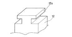
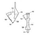
図1は、本発明の実施形態にかかる医療用チューブコネクタ装置の斜視図である。図1において、10はカテーテルからのチューブ、11は第1コネクタ本体、12は第1コネクタ11の先端に装着された保護キャップを示す。第1コネクタ本体11と保護キャップ12により第1コネクタが構成される。第1コネクタ本体11と保護キャップ12とは、第1コネクタ本体11に形成された断面T字型の凹部11aに対して保護キャップ12に形成された断面T字型の凸部12aを差し込んだ形で嵌合されている。 FIG. 1 is a perspective view of a medical tube connector device according to an embodiment of the present invention. In FIG. 1, 10 is a tube from a catheter, 11 is a first connector body, and 12 is a protective cap attached to the tip of the
次に、13はケーシング、14はケーシング13の内部にある円柱状の回転体であり、両部材により第2コネクタが構成される。ケーシング13及び回転体14の材質としては、患者が扱うものでもあり、軽量、かつ、破損しにくい材質が要求される。例えば、ポリプロピレン、ポリカーボネート等が挙げられる。また、ケーシング全体の大きさとしては、手のひらに収まる程度の大きさが好ましい。患者自身が操作しやすいようにするためである。 Next, 13 is a casing, 14 is a columnar rotating body inside the
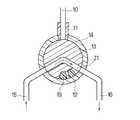
ケーシング13は、透析液注入口15、排液排出口16を有する。すなわち、透析液注入口15が透析液バッグと、排液排出口16が排液バッグとそれぞれ接続される。ケーシング13は更に、差込口13bを有し、案内キャップを構成する。回転体14は第2コネクタ本体を構成するものであり、側面に回転用把持部17を有し、円柱周面部には第1コネクタ本体11に装着された保護キャップ12を収納するキャップ収納部18を有する。図1は、差込口13bとキャップ収納部18が対面した状態を示す。19は交換用の未使用保護キャップを収納するキャップ収納部を示す。ケーシング13と回転体14を相互に回転させて、図に示すように差込口13bとキャップ収納部18が対面した状態にすれば、第1コネクタを挿入して、保護キャップ12がキャップ収納部18に納まるようにすることができる。 The
図2は、図1の医療用チューブコネクタ装置の断面図であり、図2(a)は、平面断面図、図2(b)は図2(a)のA−A’断面を示す図である。第1コネクタ本体11は、チューブ10と連通する流路となる貫通孔11bを有する。回転体14には、透析液等の液体が流れる流路21が形成されている。流路21は、流入口と流出口とが120度の角度をなしている。また、ケーシング13の差込口13b、透析液注入口15、及び排液排出口16は、互いに120度の角度をもって配置されている。従って、回転体14を回転させることにより、流路21を、チューブ10から排液排出口16への流路、透析液注入口15から排液排出口16への流路、透析液注入口15からチューブ10への流路、の3とおりに変更することができる。流路の形状については、本実施の形態のように屈曲したものに限定されるものではなく、円弧を描くような形状でも、直線上の形状でも適用可能である。 2 is a cross-sectional view of the medical tube connector device of FIG. 1, FIG. 2 (a) is a plan cross-sectional view, and FIG. 2 (b) is a view showing a cross-section AA ′ of FIG. 2 (a). is there. The first connector
また、チューブ10の先端にある保護キャップ12の形状は、角型であれ円柱型であれ特に限定されるものではないが、楔型形状を有することが望ましい。第2コネクタとの脱着を容易にするとともに、回転体14の回転によって保護キャップ12を容易に離脱させることができ、回転による保護キャップ12の移動も容易となるからである。さらに、上記の形状は、接続時において液体の流路が開通した際に液体の漏れ防止にも有効に機能する。 Further, the shape of the
また、A−A’断面図に示すように、保護キャップ12と第1コネクタ本体11とは断面T字型の凹部11aと凸部12aにより嵌合し、回転体14が回転することで、第1コネクタ本体11と保護キャップ12はスライドして離れ、第1コネクタ本体11は回転体14の周縁部に形成された断面T字型凸部をなすリブ14aと嵌合するようになる。ケーシング13の内側周縁部には全周に渡って係合用溝13aが形成され、回転体14の外側周縁部にはその溝に係合できるようにリブ14aが形成されている。 Further, as shown in the AA ′ cross-sectional view, the
上記の構成において、患者の誤操作を防止すべく、流路21が、透析液注入口15、排液排出口16またはキャップ収納部18の位置まで回転した場合には、嵌合感と共に固定される構造を有することが好ましい。あるいは、指定位置にその旨の表示を行うものでも良い。さらに、一方向にしか回転できない構成とすることにより誤操作を防止するのも効果的である。また、実際の液体の流れを目視確認できるよう、ケーシング13及び回転体14を透明若しくは半透明にすることもできる。 In the above configuration, when the
図3は、保護キャップ12の接続部分の拡大図である。保護キャップ12は断面T字型の凸部12aを有する。上述のように、回転体14の周縁部にも保護キャップ12と同様の断面T字型の凸部が形成されている。一方第1コネクタ本体11は、上述のように、かかる凸部と嵌合する形状の断面T字型の凹部を有する。 FIG. 3 is an enlarged view of a connection portion of the
保護キャップにおける第1コネクタ本体との結合部分の断面形状は、図3のようなT字型の形態に限定されるものではない。例えば、図4に示すような台形状の形態を有するものであっても、図5に示すような円状若しくは楕円状の形態を有するものであってもよい。嵌合した場合に、長手方向に離脱しにくい形態でありさえすれば、どのような形態であっても良い。 The cross-sectional shape of the joint portion of the protective cap with the first connector body is not limited to the T-shaped form as shown in FIG. For example, even if it has a trapezoidal shape as shown in FIG. 4, it may have a circular or elliptical shape as shown in FIG. Any form is acceptable as long as it is a form that is difficult to be removed in the longitudinal direction when fitted.
また、どのような形態をしていても、回転体14の周縁部には同様の断面型を有する凸部が形成され、形成された凸部の中心部には、図2に示した流路21の流出入口をなす孔が開口している。断面T字型の場合においては、図6に示すように流出入口21aが形成される。 Moreover, a convex part having the same cross-sectional shape is formed on the peripheral part of the
図7は、図1の医療用チューブコネクタ装置の一部を示す断面図であり、第1コネクタ本体11と回転体14の接続状態を示す。回転体14が回転して、流路21が第1コネクタ本体11の貫通孔11bと連結すると、透析液若しくは排液が回転体14の内部を流れることが可能となる。この際に当該液体が外部に漏れないように工夫をする必要がある。そこで、「O」リング71等を回転体14の周縁部に形成された凸部14aに装着しておくことにより、連結時の透析液若しくは排液の漏れを防止することが可能となる。「O」リング等はシリコンゴム等のエラストマー材料で製造するのが好ましい。 FIG. 7 is a cross-sectional view showing a part of the medical tube connector device of FIG. 1 and shows a connection state of the
以下、図1の医療用チューブコネクタ装置の動作について、図8から図13を参照して説明する。 Hereinafter, the operation of the medical tube connector device of FIG. 1 will be described with reference to FIGS. 8 to 13.
まず図8に示すように、第1コネクタ本体11を保護キャップ12ごと差込口13aから挿入する。 First, as shown in FIG. 8, the first connector
次に、第1コネクタを保持した状態で回転体14を回転させ、図9に示すように、流路21によりチューブ10と排液排出口16とを連結する。回転することにより、回転体14の周縁部に形成された凸部と第1コネクタ本体11の凹部とが嵌合し、第1コネクタ本体11は回転体14に保持される。このようにして、チューブ10は排液バッグと連結され、腹膜内に溜まっている液を排液バッグへと排出することが可能となる。 Next, the rotating
次に、回転体14を120度回転させて、図10に示すように、排液用接続口16と透析液注入口15とを流路21で連結させる。透析液を直接排液バッグへ排出することにより、回転体14の内部の流路21の内側に付着している排液の残りを洗浄し、流路21内に液を満たすプライミング操作が可能となる。かかる作業は、流路の洗浄とプライミングのためである。洗浄(プライミング)操作が終了したら、さらに回転体14を120度回転させて、図11に示すように、透析液注入口15とチューブ10とを流路21で連結する。そして、透析液を体内へと注入する。 Next, the rotating
注液操作が終了したら、図12に示す状態に回転させることにより、未使用保護キャップ19が第1コネクタ本体11に嵌合する。嵌合することにより、未使用保護キャップ19のロックがはずれ、未使用保護キャップ19が回転体14から脱離し、チューブ10を第2コネクタから切り離すことができる。すなわち、図13に示すように、未使用保護キャップ19が第1コネクタ本体11に結合した状態でチューブ10が本装置から切り離されるので、患者の手によって流路を汚染することなく保護キャップの脱着・交換を終了することができ、清潔さを確保して容易に透析作業を行うことができる。 When the liquid injection operation is completed, the unused
なお図8に示したように第1コネクタ本体11を挿入した際に、保護キャップ12と回転体14との連結を保持するために、バネ系の弾性体を活用した機構を用いたり、機械的なロック機構を用いることができる。 As shown in FIG. 8, when the first connector
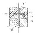
例えば、図14に示すように、保護キャップ12に素材自身の弾性若しくはバネ等の機構によって突出したり引っ込んだりすることができる保持部12bを設け、回転体14側に保持部12bと係合可能な窪み14cを設ける。これにより、第1コネクタを保護キャップ12ごとキャップ収納用窪み18へ挿入した場合に、保持部12bによってロックされ、回転体14を回転させていない状態でも容易に外れないようにすることができる。 For example, as shown in FIG. 14, the
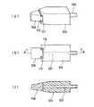
また、図15に示すように、第1コネクタ本体11と保護キャップ12との嵌合部の近傍30が空気中の細菌等で汚染されていると、使用時に好ましくない。そこで、第1コネクタ本体11の外側に、流路方向に移動できる保護カバー31を設けることが効果的である。すなわち、使用しない時には、保護キャップ12を覆うように保護カバー31を下ろして連結部分の近傍30を保護し、使用する時には保護カバー31を上げて使用する。 Further, as shown in FIG. 15, if the
保護カバーは、図16に示すような構造で流路方向に移動するように構成することができる。第1コネクタ本体40はガイド部41を有し、ガイド部41に案内されて摺動可能な摺動部材42が設けられている。ガイド部41の内側の空隙部分には、スプリング44が装着され、摺動部材42を外向きに付勢している。摺動部材42は、保護キャップ12を覆う位置と露出する位置とをとることができる。図16(a)に示すように、保護キャップ12を覆う位置で摺動部材42に保護カバー43を装着する。使用に際しては、図16(b)に示すように、保護カバー43を外し、摺動部材42を後退させて、保護キャップ12を露出させる。摺動部材42は、スプリング44により保護キャップ12を覆う位置に付勢されているので、不使用時には、保護キャップ12は簡易にしかも確実にカバーされる。 The protective cover can be configured to move in the flow path direction with a structure as shown in FIG. The
また、流出入口が3つある場合には、使用済み保護キャップが収納されるキャップ収納用窪み18と、未使用保護キャップが収納されるキャップ収納用窪み19のなす円周角が120度以内の近傍にあることが好ましい。さらに、キャップ収納用窪み窪み18とキャップ収納用窪み19は、流路によって区分される2つの区域のうち同一区域内に設けられることが好ましい。流路切替えとの整合性を図るためである。 In addition, when there are three outflow inlets, the circumferential angle formed by the
さらに、使用済み保護キャップを未使用保護キャップへと交換する場合、交換作業を患者自身の手で行うのでは、保護キャップが患者の手によって汚染される可能性がある。かかる汚染を未然に防止すべく、初期出荷時に未使用保護キャップを本装置に装着しておくことも効果的である。 Further, when the used protective cap is replaced with an unused protective cap, if the replacement operation is performed by the patient's own hand, the protective cap may be contaminated by the patient's hand. In order to prevent such contamination, it is also effective to attach an unused protective cap to the apparatus at the time of initial shipment.
以上のように本実施の形態によれば、患者自身の手によって、容易に腹膜透析を確実に行うことができ、また保護キャップ取り替えが人手を介さずに行うことができるので、汚染されること無く清潔に腹膜透析を行うことが可能となる。 As described above, according to the present embodiment, the peritoneal dialysis can be easily and reliably performed by the patient's own hand, and the protective cap can be replaced without human intervention. It is possible to perform peritoneal dialysis cleanly.
(実施の形態2)
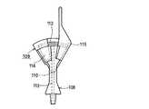
図17は、本発明の実施の形態2における医療用チューブコネクタ装置を示す平面図である。101は第1コネクタ、102は第2コネクタであり、図示していないが、各々液体の流路を構成するチューブに接続され、両コネクタ101,102を結合することにより、液体の流路が連通する。両コネクタ101,102は接続・脱離が自在である。(Embodiment 2)
FIG. 17 is a plan view showing a medical tube connector device according to Embodiment 2 of the present invention.
第1コネクタ101は、第1コネクタ本体103と第1キャップ104からなる。第1キャップ104は、第1コネクタ本体103に対して着脱自在である。第1コネクタ本体103には、チューブ(図示せず)と接続するための接続部105が形成されている。第1コネクタ本体103の内部には、接続部105から第1キャップ104が装着された側の端部106まで貫通する流路107が形成されている。第1キャップ104は、装着された状態において、流路107の端部106を覆い、封止する。 The
第2コネクタ102は、第2コネクタ本体108と、第2コネクタ本体108に対して変位可能なように設けられた案内キャップ109からなる。案内キャップ109の変位は、軸110を中心とした回動による。 The
第2コネクタ本体108には、チューブ(図示せず)と接続するための接続部111が形成されている。第2コネクタ本体108の内部には、接続部111から反対側の端部112まで貫通する流路113が形成されている。第2コネクタ本体108は、流路113に隣接して、凹部114を有する。 The second connector
案内キャップ109には、カバー部115が設けられている。カバー部115は、図17に示す状態、すなわち第2コネクタ本体108が右周り終端(以下回動右端という)まで回動した状態で、第2コネクタ本体108の先端部分をカバーする。この状態においてカバー部115は、第2コネクタ本体108の端部112を覆って封止する。カバー部115からはつまみ121が延びている。案内キャップ109にはさらに、カバー部115に隣接して開口部119が形成されている。図17のように開口部119に第2コネクタ本体108の凹部114が位置する状態では、凹部114が外部に対して開口し、第1コネクタ101の第1キャップ104を挿入可能である。さらに、開口部119に隣接して第1キャップの収納部120が形成されている。 The
次に、図18を参照して、第1コネクタ101の構造について、より詳細に説明する。図18(a)は第1コネクタ101の斜視図、(b)は同正面図、(c)は(b)のA−A断面図である。第1キャップ104は、T字型の断面をなす凸状係合部116を有する。第1コネクタ本体103には、凸状係合部116と嵌合する断面T字型の凹状係合部117を有する。凸状係合部116を凹状係合部117に対して摺動させることにより、第1キャップ104を第1コネクタ本体103に対して着脱する。 Next, the structure of the
次に、図19〜図22を参照して、第2コネクタ102の構造について、より詳細に説明する。図19は、第2コネクタ本体108と、案内キャップ109とを分解して示した図である。図19には第1コネクタを示していないが、第1コネクタと第2コネクタの各流路を連結した前記接続状態で、第2コネクタ本体108と案内キャップ109とは上下方向に脱離可能である。図20は、第2コネクタ本体108が左周り終端(以下回動左端という)まで回動した状態を示す。実際に使用する場合は、このような状態にはならないが、構造の理解のために示したものである。この状態では、端部112が露出しており、流路113が終端で開口している。 Next, the structure of the
図21の(a)は第2コネクタ本体108の平面図、(b)は正面図、(c)は背面図である。第2コネクタ本体108には、回動中心孔118が形成され、第2コネクタ本体108と案内キャップ109を係合させた時には、回動中心孔118と軸110が嵌合する。第2コネクタ本体108の端部112は、図21(b)に示したように、第1キャップ104の凸状係合部116と同様のT字型断面をした凸状係合部112aを有する。従って端部112は、この凸状係合部112aにより第1コネクタ本体3の凹状係合部117と嵌合可能である。凹部114は、第1コネクタ1が挿入された際に、第1キャップ104が収容され、第1コネクタ本体103は収容されない寸法となっている。 21A is a plan view of the second connector
図22の(a)は案内キャップ109の平面図、(b)は正面図である。案内キャップ109のカバー部115には、図17に示したように、回動によって第2コネクタ本体108の端部112が収容される。カバー部115には、係合部115aが形成されている。この凹状係合部115aは、第1コネクタ本体103の凹状係合部117と同様の形状であり、従って、図17に示した状態において、第2コネクタ本体108の凸状係合部112a(図21(b)参照)と嵌合する。収納部120は、凹状係合部115aと同様の断面形状を持つ係合部120aを有し、回動によって第1キャップを収容することができる。 22A is a plan view of the
上記構造の第2コネクタ本体108と案内キャップ109とを相対的に回動させ、図17に示すように、回動右端において第2コネクタ本体108の端部112がカバー部115に封止された状態は、流路接続前の準備状態である。図20に示すように、回動左端において端部112が開口部119に面し、流路113の先端が露出した状態は、流路が接続された接続状態である。但し、図20は第2コネクタ102のみを示したものであり、実際の使用時には、後述するように、端部112に対して第1コネクタ本体103が結合した状態になる。 The
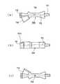
次に、第1コネクタ1と第2コネクタ102を接続・脱離する際の操作について図23および図24を参照して説明する。図23(a)に示す状態では、第2コネクタ102は準備状態にあり、第1キャップ104が第2コネクタ本体108の凹部114に挿入されている。図23(b)は、第2コネクタ本体108を少し左回りに回動させた状態を示す。回動に伴い、第2コネクタ本体108の端部112の側壁に押されて、第1キャップ104が第1コネクタ本体103の凹状係合部117を摺動し、収納部120に向かって移動する。同時に、第2コネクタ本体108の凸状係合部112aは、第1コネクタ本体103の凹状係合部117に対して摺動により嵌合し始める。すなわち、凹状係合部117に対する嵌合に関して、第1キャップ104と第2コネクタ本体108の端部112とが入れ替わることになる。 Next, operations for connecting / disconnecting the first connector 1 and the
図23(c)は、第2コネクタ本体108を回動左端まで回動させた状態を示す。この状態において、第1キャップ104と端部112とは完全に入れ替わっている。すなわち、第1キャップ104は収納部120に収容され、端部112は第1コネクタ本体103と対向する。それにより、第1コネクタ本体103の流路107と第2コネクタ本体108の流路113が接続され連通する。第1コネクタ本体103と端部112は、第1コネクタ本体103と第1キャップ104の結合と同様の状態に結合しているので、はずれることはない。 FIG. 23C shows a state in which the second connector
この状態において、前述のように、案内キャップ109から第2コネクタ本体108を脱離させることができる。図24は、案内キャップ109を除いた状態を示す。この状態において、案内キャップ109は、第1キャップ104を収納部120に保持している。通常の使用に際しては、新しい第1キャップ104を新しい案内キャップ109に収納したものを準備し、それを第2コネクタ本体108に改めて装着し、回動した後、後述の第1コネクタと第2コネクタの接続を解除する操作を行う。 In this state, as described above, the
次に、第1コネクタと第2コネクタを相互に脱離させる操作について説明する。すなわち、図23(c)の状態から図23(a)の状態に回動させることにより、第1コネクタ本体103に対して第1キャップ104が装着され、第2コネクタ本体108の端部112はカバー部115に収容され、流路113は封止される。以上の操作において、第1コネクタ本体103から第1キャップ104を脱着する際も、コネクタの流路は保護されており、汚染から防護することができる。 Next, an operation for detaching the first connector and the second connector from each other will be described. That is, by rotating from the state of FIG. 23C to the state of FIG. 23A, the
なお、上記の操作を行う際には、第1コネクタ本体103をつまみ121とともに握って、第2コネクタ本体108を回動させれば、第1コネクタ本体103と第2コネクタ本体108の脱着を、安定して操作することができる。 When performing the above operation, if the
上記構成の医療用チューブコネクタ装置を用いたコネクタ脱着操作および注・排液操作を伴う腹膜透析は、透析液バッグと排液バッグとが別個に脱着されるシングルバッグシステムでは、以下のように行われる。 Peritoneal dialysis with connector detachment operation and injection / drainage operation using the medical tube connector device with the above configuration is performed as follows in a single bag system in which the dialysis fluid bag and the drainage bag are separately detached. Is called.
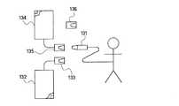
(1) 排液バッグとの接続: 図25に示すように、患者側の導管コネクタ131を第1コネクタ(第1キャップ付き)により構成する。排液バッグ側の導管コネクタ133を、導管によって排液バッグ132に連結された第2コネクタ(案内キャップ付き)により構成する。患者と排液バッグ132の接続は、導管コネクタ131と導管コネクタ133を接続することにより行う。 (1) Connection with Drainage Bag: As shown in FIG. 25, the patient-
(2) 排液: コネクタ装置を前記「準備状態」から前記「接続状態」に変位させ、排液バッグ側と患者側の流路を連結した後、患者体内からの貯留液を排液バッグ132に排出する。 (2) Drainage: After the connector device is displaced from the “prepared state” to the “connected state”, the drainage bag side and the patient-side flow path are connected, and then the stored liquid from the patient body is drained by the
(3) 排液バッグとの脱離: コネクタ装置を前記「接続状態」から前記「準備状態」に変位させ、流路を閉止状態にする。導管コネクタ131と導管コネクタ133を脱離し、貯留排液の入った排液バッグ132を廃棄する。患者は排液バッグ132から解放される。導管コネクタ131には第1キャップが装着されており、汚染から防止される。 (3) Desorption from the drainage bag: The connector device is displaced from the “connected state” to the “prepared state”, and the flow path is closed. The
(4) 透析液バッグとの接続: 導管によって透析液バッグ134に連結された透析液バッグ側の導管コネクタ135(第2コネクタの構成を有する)に、導管コネクタ131を接続する。透析液バッグに連結した導管コネクタ135には、第1キャップを収納するための収納部120を設けても良いが、無くても特に問題ない。 (4) Connection with the dialysate bag: The
(5) 透析液注入: コネクタ装置を前記「準備状態」から前記「接続状態」に変位させ、透析液バッグ側と患者側の流路を連結した後、患者体内に新しい透析液を注入する。 (5) Dialysate injection: The connector device is displaced from the “prepared state” to the “connected state”, the dialysate bag side and the patient side flow path are connected, and then a new dialysate is injected into the patient.
(6) キャップ交換: 透析液側と患者側の流路を連結した「接続状態」のまま、第2コネクタより構成される導管コネクタ135から、案内キャップを脱離させる。このとき、導管コネクタ131の第1キャップは案内キャップに取り残されたままである。即ち、導管コネクタ131と導管コネクタ135とは、第1コネクタ本体と第2コネクタ本体同士が接続された状態で、第1キャップを保持した案内キャップ脱離する。(この交換用の案内キャップには、第1キャップを収容する収容部120が必要である。)次に、透析液バッグと一緒に包装されている新しい案内キャップ136(新しい第1キャップの装着されたもの)に、本体同士が接続した上記コネクタ(第1および第2)を接合させる。これによって、導管コネクタ135は新しい第1および案内キャップと交換されたことになる。 (6) Cap replacement: The guide cap is detached from the
(7)透析液バッグとの脱離: 導管コネクタ135において、案内キャップに対し第2コネクタ本体を変位させ、前記「接続状態」から前記「準備状態」にして、流路を閉止した後、導管コネクタ135と導管コネクタ131とを脱離させる。このとき、導管コネクタ131には新しい第1キャップが装着されている。以上の操作によって、患者は透析液バッグ134から解放される。また、脱離した導管コネクタ135が接続された透析液バッグ134は、次回の排液バッグとして使用できるので、次の排液時まで保管しておくのが望ましい。 (7) Desorption from dialysate bag: In the
なお、上記操作の記述において簡単に説明したように、透析液バッグ134に最初に連結している導管コネクタ135の案内キャップには収納部120は特に無くても問題ないが、(6)のキャップ交換される案内キャップには(第1キャップを収納する)収納部120を設けることが望ましい。 As briefly described in the above description of the operation, the guide cap of the
以上は、シングルバッグシステムの場合について記載したが、本発明の装置は、図26に示したように、排液バッグと患者接続部と透析液バッグ接続部とが分岐管で連結されたバッグフリーシステム140にも、適用可能である。また、図27に示したように、ツインバッグシステム141と組み合わせた使用形態をとることもできる。さらに、図28に示したように、注入・排液および調合等を自動で行うAPD(自動腹膜透析)装置142にも適用可能である。図26〜12において、図25と同一の部材については、同一の番号を付して、説明を省略する。 Although the above has described the case of a single bag system, as shown in FIG. 26, the apparatus of the present invention is a bag-free device in which a drainage bag, a patient connection part, and a dialysate bag connection part are connected by a branch pipe. The
図26、27のバッグフリーシステム140やツインバッグシステム141等のように、2つのバッグを連結した状態で液を注入、排液する場合は、実施の形態1で示した構造の第2コネクタ138を用い、第1コネクタ131との脱着を行うようにした方がより簡便に操作できる。 When injecting and draining liquid with two bags connected, such as the bag-
また、図28に示すAPD装置142で複数の透析液バッグからの調合を行う場合に使用するコネクター、すなわち図28に示す、導管コネクタ139(第1コネクタ)に接続される透析液側の導管コネクタ135は、「準備状態」から「接続状態」に移行した後に再度「準備状態」に戻る必要はなく、「接続状態」のままで廃棄するように簡素化しても良い。しかし、この場合でも患者側の導管コネクタ131と接続される導管コネクタ137は、患者側コネクタにキャップを装着する必要があるため、「準備状態」→「接続状態」→「準備状態」となるような機構が必要である。 Further, the connector used when the
本発明の医療用チューブコネクタ装置によれば、コネクタの接続・脱離がコネクタに設けた流路端部の露出を伴わなずに行われるため、外気中に浮遊する細菌による汚染から防護でき、また、脱着時に患者が接続部に直接手を触れることがないため、流路端部が手指により汚損されることがない。さらに、コネクタの接続・脱離の操作は、特別な器具を用いることもなく、極めて容易である。 According to the medical tube connector device of the present invention, since connection / disconnection of the connector is performed without exposure of the end of the flow path provided in the connector, it can be protected from contamination by bacteria floating in the outside air, In addition, since the patient does not directly touch the connection part at the time of detachment, the end of the channel is not soiled by fingers. Furthermore, the operation of connecting / disconnecting the connector is extremely easy without using a special instrument.
Claims (19)
Translated fromJapanese内部を貫通する流路(11b, 107)を有しその流路の一端部でチューブと接続可能な第1コネクタ本体(11, 103)、及び前記第1コネクタ本体(11, 103)に対して着脱自在でありその装着された状態において前記流路の他端部を覆って封止する保護キャップ(12, 104)を含む第1コネクタと、
内部を貫通する流路(21, 113)を有するとともに前記第1コネクタの保護キャップ(12, 104)を挿入可能な凹部(18, 114)が形成され、前記流路(21, 113)の一端部でチューブと接続可能な第2コネクタ本体(14, 108)、及び前記第2コネクタ本体(14, 108)に対して変位可能に設けられ前記第2コネクタ本体(14, 108)の前記流路(21, 113)の他端部を覆って封止するカバー部(13, 115)が形成された案内キャップ(13, 109)を含む第2コネクタとを備え、
前記保護キャップ(12, 104)が前記第1コネクタ本体(11, 103)に対して前記流路の方向に直交する方向の移動によって脱着可能に構成され、
前記案内キャップ(13, 109)は、前記第2コネクタ本体(14, 108)に対して回動変位可能であって、前記第2コネクタ本体(14, 108)の前記凹部(18, 114)と前記流路(21, 113)の前記他端部とは、前記回動変位可能な方向に並んで配置され、
前記第2コネクタ本体(14, 108)と前記案内キャップ(13, 109)とは前記回動変位可能な方向における相対的な回動変位により、前記第2コネクタ本体(14, 108)の前記凹部(18, 114)が開放されるとともに前記流路(21, 113)の端部が前記カバー部(13, 115)により封止された準備状態と、前記流路(21, 113)の端部が開放された接続状態とをとることが可能なように構成され、
前記準備状態において、前記保護キャップ(12, 104)を装着した第1コネクタを前記凹部(18, 114)に挿入した後、前記第2コネクタ本体(14, 108)と案内キャップ(13, 109)とを相対的に回動変位させて前記接続状態にすることにより、前記保護キャップ(12, 104)が前記凹部(18, 114)に保持されて前記流路の方向に直交する方向に移動し前記第1コネクタ本体(11, 103)から脱離して、前記案内キャップ(13, 109)に保持された状態になるとともに、前記第1コネクタ本体(11, 103)と前記第2コネクタ本体(14, 108)とが接続されて流路が連通することを特徴とする医療用チューブコネクタ装置。In a medical tube connector device including two connectors that are connectable and detachable to each other for connecting tubes,
A first connector body (11, 103) having a flow path (11b, 107) penetrating through the inside and connectable to a tube at one end of the flow path, and the first connector body (11, 103) A first connector including a protective cap (12, 104) that is detachable and covers and seals the other end of the channel in the mounted state;
A recess (18, 114) having a channel (21, 113) penetrating through the inside and into which the protective cap (12, 104) of the first connector can be inserted is formed, and one end of the channel (21, 113) The second connector body (14, 108) connectable to the tube at the portion, and the flow path of the second connector body (14, 108) provided to be displaceable with respect to the second connector body (14, 108) A second connector including a guide cap (13, 109) formed with a cover (13, 115) that covers and seals the other end of (21, 113),
The protective cap (12, 104) is configured to be removable with respect to the first connector body (11, 103) by movement in a direction perpendicular to the direction of the flow path,
The guide cap (13, 109) can be rotated and displaced with respect to the second connector body (14, 108), and the guide cap (13, 109) and the recess (18, 114) of the second connector body (14, 108). The other end of the flow path (21, 113) is arranged side by side in the rotationally displaceable direction,
The second connector main body (14, 108) and the guide cap (13, 109) are displaced relative to each other in the direction in which the second connector main body (14, 108) can rotate. (18, 114) is opened and the end of the channel (21, 113) is sealed by the cover (13, 115), and the end of the channel (21, 113) Is configured to be able to take an open connection state,
In the preparatory state, after the first connector with the protective cap (12, 104) is inserted into the recess (18, 114), the second connector body (14, 108) and the guide cap (13, 109) And the protective cap (12, 104) is held in the recess (18, 114) and moved in a direction perpendicular to the direction of the flow path. The first connector body (11, 103) and the second connector body (14) are detached from the first connector body (11, 103) and are held by the guide cap (13, 109). , 108) and the flow path communicates with each other, and a medical tube connector device.
円環状をなし、その周縁部に、チューブと接続可能な少なくとも1つの液体の流出入口(15, 16)、及び前記第1コネクタを差し込むことのできる差込口(13b)を有し、前記案内キャップ(13)を構成するケーシング(13)と、
前記ケーシング(13)内に回転可能なように装着された略円柱状の本体からなり、その円柱内部を貫通し円柱周面に流出入口を形成する液体の流路(21)、及び前記円柱周面に形成され前記第1コネクタに装着された保護キャップ(12)を収納可能な少なくとも1つのキャップ収納用窪み(18)を有し、前記第2コネクタ本体(14)を構成する回転体(14)とを備え、
前記回転体(14)と前記ケーシング(13)とは相対的な回転位置により準備状態と接続状態とを取ることができ、前記準備状態においては、前記ケーシング(13)の差込口(13b)が前記回転体(14)のキャップ収納用窪み(18)に面して前記回転体(14)の流路(21)の流出入口は前記ケーシング(13)により封止され、前記接続状態においては、前記ケーシング(13)の差込口(13b)が前記回転体(14)の流路(21)の流出入口の1つに面するとともに前記ケーシング(13)の流出入口(15, 16)と前記回転体(14)の流路(21)の他の流出入口とが連通するように構成され、
前記準備状態において、前記第1コネクタを前記保護キャップ(12)の側から前記差込口(13b)を通して前記キャップ収納用窪み(18)に挿入した後、前記回転体(14)と前記ケーシング(13)とを前記接続状態にすることにより、前記保護キャップ(12)が前記回転体(14)のキャップ収納用窪み(18)に保持されて移動し前記第1コネクタ本体(11)から脱離するとともに、前記第1コネクタ本体(11)と前記回転体(14)の流路(21)が連通する請求項1に記載の医療用チューブコネクタ装置。The second connector is
The guide has at least one liquid outflow port (15, 16) connectable with a tube and an insertion port (13b) into which the first connector can be inserted at a peripheral portion of the guide. A casing (13) constituting a cap (13);
A liquid flow path (21) comprising a substantially cylindrical body rotatably mounted in the casing (13), penetrating through the inside of the cylinder and forming an outflow inlet on the circumferential surface of the cylinder, and the circumference of the cylinder A rotating body (14) having at least one cap storage recess (18) formed on the surface and capable of storing a protective cap (12) attached to the first connector, and constituting the second connector body (14). )
The rotating body (14) and the casing (13) can be in a ready state and a connected state depending on their relative rotational positions. In the ready state, the insertion port (13b) of the casing (13) There inflow and outflowmouthof the channel (21) of the rotating body facing the cap for housing recess (18) of the rotating body (14) (14)is sealed by said casing (13), in the connected state the outflow inlet (15, 16 of the with the outlet of the casing (13) (13b) facing the oneof the inflow and outflowmouthof the channel (21) of the rotating body (14) the casing (13) )and the other inflow and outflowmouthof the channel (21) of the rotating body (14) is configured to communicate,
In the preparatory state, after inserting the first connector from the protective cap (12) side into the cap housing recess (18) through the insertion port (13b), the rotating body (14) and the casing ( 13) in the connected state, the protective cap (12) moves while being held in the cap housing recess (18) of the rotating body (14) and detached from the first connector body (11). In addition, the medical tube connector device according to claim 1, wherein the first connector body (11) and the flow path (21) of the rotating body (14) communicate with each other.
内部を貫通する流路(11b, 107)を有しその流路の一端部でチューブと接続可能な第1コネクタ本体(11, 103)、及び前記第1コネクタ本体(11, 103)に対して着脱自在でありその装着された状態において前記流路の他端部を覆って封止する保護キャップ(12, 104)を含む第1コネクタと、
内部を貫通する流路(21, 113)を有するとともに前記第1コネクタの保護キャップ(12, 104)を挿入可能な凹部(18, 114)が形成され、前記流路(21, 113)の一端部でチューブと接続可能な第2コネクタ本体(14, 108)、及び前記第2コネクタ本体(14, 108)に対して変位可能に設けられ前記第2コネクタ本体(14, 108)の前記流路(21, 113)の他端部を覆って封止するカバー部(13, 115)が形成された案内キャップ(13, 109)を含む第2コネクタとを備え、
前記第2コネクタ本体(14, 108)と前記案内キャップ(13, 109)とは相対的な変位により、前記第2コネクタ本体(14, 108)の前記凹部(18, 114)が開放されるとともに前記流路(21, 113)の端部が前記カバー部(13, 115)により封止された準備状態と、前記流路(21, 113)の端部が開放された接続状態とをとることが可能なように構成され、
前記準備状態において、前記保護キャップ(12, 104)を装着した第1コネクタを前記凹部(18, 114)に挿入した後、前記第2コネクタ本体(14, 108)と案内キャップ(13, 109)とを前記接続状態にすることにより、前記保護キャップ(12, 104)が前記凹部(18, 114)に保持されて移動し前記第1コネクタ本体(11, 103)から脱離して、前記案内キャップ(13, 109)に保持された状態になるとともに、前記第1コネクタ本体(11, 103)と前記第2コネクタ本体(14, 108)とが接続されて流路が連通し、
前記接続状態から、前記第2コネクタ本体(14, 108)と案内キャップ(13, 109)とを相対的に変位させて前記準備状態に戻すことにより、前記保護キャップ(12, 104)が前記第1コネクタ本体(11, 103)に装着されるとともに、前記第2コネクタ本体(14, 108)の流路端部が前記カバー部(13, 115)により封止されることを特徴とする医療用チューブコネクタ装置。In a medical tube connector device including two connectors that are connectable and detachable to each other for connecting tubes,
A first connector body (11, 103) having a flow path (11b, 107) penetrating through the inside and connectable to a tube at one end of the flow path, and the first connector body (11, 103) A first connector including a protective cap (12, 104) that is detachable and covers and seals the other end of the channel in the mounted state;
A recess (18, 114) having a channel (21, 113) penetrating through the inside and into which the protective cap (12, 104) of the first connector can be inserted is formed, and one end of the channel (21, 113) The second connector body (14, 108) connectable to the tube at the portion, and the flow path of the second connector body (14, 108) provided to be displaceable with respect to the second connector body (14, 108) A second connector including a guide cap (13, 109) formed with a cover (13, 115) that covers and seals the other end of (21, 113),
When the second connector body (14, 108) and the guide cap (13, 109) are relatively displaced, the recesses (18, 114) of the second connector body (14, 108) are opened. The prepared state in which the end of the flow path (21, 113) is sealed by the cover (13, 115) and the connected state in which the end of the flow path (21, 113) is opened. Is configured to be possible,
In the preparatory state, after the first connector with the protective cap (12, 104) is inserted into the recess (18, 114), the second connector body (14, 108) and the guide cap (13, 109) , The protective cap (12, 104) moves while being held in the recess (18, 114) and is detached from the first connector body (11, 103). (13, 109) and the first connector main body (11, 103) and the second connector main body (14, 108) are connected, and the flow path communicates,
From the connected state, the second connector body (14, 108) and the guide cap (13, 109) are relatively displaced to return to the ready state, whereby the protective cap (12, 104) is moved to the first state. A medical connector characterized in that it is attached to one connector body (11, 103) and the flow path end of the second connector body (14, 108) is sealed by the cover portion (13, 115). Tube connector device.
内部を貫通する流路(11b, 107)を有しその流路の一端部でチューブと接続可能な第1コネクタ本体(11, 103)、及び前記第1コネクタ本体(11, 103)に対して着脱自在でありその装着された状態において前記流路の他端部を覆って封止する保護キャップ(12, 104)を含む第1コネクタと、
内部を貫通する流路(21, 113)を有するとともに前記第1コネクタの保護キャップ(12, 104)を挿入可能な凹部(18, 114)が形成され、前記流路(21, 113)の一端部でチューブと接続可能な第2コネクタ本体(14, 108)、及び前記第2コネクタ本体(14, 108)に対して変位可能に設けられ前記第2コネクタ本体(14, 108)の前記流路(21, 113)の他端部を覆って封止するカバー部(13, 115)が形成された案内キャップ(13, 109)を含む第2コネクタとを備え、
前記第2コネクタ本体(14, 108)と前記案内キャップ(13, 109)とは相対的な変位により、前記第2コネクタ本体(14, 108)の前記凹部(18, 114)が開放されるとともに前記流路(21, 113)の端部が前記カバー部(13, 115)により封止された準備状態と、前記流路(21, 113)の端部が開放された接続状態とをとることが可能なように構成され、
前記準備状態において、前記保護キャップ(12, 104)を装着した第1コネクタを前記凹部(18, 114)に挿入した後、前記第2コネクタ本体(14, 108)と案内キャップ(13, 109)とを前記接続状態にすることにより、前記保護キャップ(12, 104)が前記凹部(18, 114)に保持されて移動し前記第1コネクタ本体(11, 103)から脱離して、前記案内キャップ(13, 109)に保持された状態になるとともに、前記第1コネクタ本体(11, 103)と前記第2コネクタ本体(14, 108)とが接続されて流路が連通し、
前記保護キャップ(12, 104)は、円弧に沿った摺動により、前記第1コネクタ本体(11, 103)に対して着脱可能であり、前記第2コネクタ本体(14, 108)と前記案内キャップ(13, 109)とは、円弧に沿った摺動によって相対的に変位可能であって、前記第1コネクタ本体(11, 103)と前記保護キャップ(12, 104)の摺動面に対応する円弧と、前記第2コネクタ本体(14, 108)と前記案内キャップ(13, 109)の摺動面に対応する円弧は、半径が同一の円周上にあり、
前記準備状態において、前記第1コネクタを前記保護キャップ(12, 104)の側から前記凹部(18, 114)に挿入したとき、前記第1コネクタ本体(11, 103)と前記保護キャップ(12, 104)の摺動面、および前記第2コネクタ本体(14, 108)と前記案内キャップ(13, 109)の摺動面が、同一円弧上に並ぶように構成したことを特徴とする医療用チューブコネクタ装置。In a medical tube connector device including two connectors that are connectable and detachable to each other for connecting tubes,
A first connector body (11, 103) having a flow path (11b, 107) penetrating through the inside and connectable to a tube at one end of the flow path, and the first connector body (11, 103) A first connector including a protective cap (12, 104) that is detachable and covers and seals the other end of the channel in the mounted state;
A recess (18, 114) having a channel (21, 113) penetrating through the inside and into which the protective cap (12, 104) of the first connector can be inserted is formed, and one end of the channel (21, 113) The second connector body (14, 108) connectable to the tube at the portion, and the flow path of the second connector body (14, 108) provided to be displaceable with respect to the second connector body (14, 108) A second connector including a guide cap (13, 109) formed with a cover (13, 115) that covers and seals the other end of (21, 113),
When the second connector body (14, 108) and the guide cap (13, 109) are relatively displaced, the recesses (18, 114) of the second connector body (14, 108) are opened. The prepared state in which the end of the flow path (21, 113) is sealed by the cover (13, 115) and the connected state in which the end of the flow path (21, 113) is opened. Is configured to be possible,
In the preparatory state, after the first connector with the protective cap (12, 104) is inserted into the recess (18, 114), the second connector body (14, 108) and the guide cap (13, 109) , The protective cap (12, 104) moves while being held in the recess (18, 114) and is detached from the first connector body (11, 103). (13, 109) and the first connector main body (11, 103) and the second connector main body (14, 108) are connected, and the flow path communicates,
The protective cap (12, 104) can be attached to and detached from the first connector body (11, 103) by sliding along an arc, and the second connector body (14, 108) and the guide cap (13, 109) is relatively displaceable by sliding along an arc, and corresponds to the sliding surface of the first connector body (11, 103) and the protective cap (12, 104). The arc and the arc corresponding to the sliding surface of the second connector main body (14, 108) and the guide cap (13, 109) are on the same radius.
In the preparatory state, when the first connector is inserted into the recess (18, 114) from the protective cap (12, 104) side, the first connector body (11, 103) and the protective cap (12, 104) 104) and the sliding surface of the second connector main body (14, 108) and the guide cap (13, 109) are arranged on the same arc. Connector device.
前記準備状態において、前記保護キャップ(12, 104)を前記凹部(18, 114)に挿入したとき、前記保護キャップ(12, 104)と前記第2コネクタ本体(14, 108)の前記凸状および凹状係合部が同一円弧上に並び、
前記接続状態において、前記第1コネクタ本体(11, 103)と前記第2コネクタ本体(14, 108)の前記凸状および凹状係合部が嵌合することにより、前記第1コネクタ本体(11, 103)と前記第2コネクタ本体(14, 108)とが結合するように構成した請求項15記載の医療用チューブコネクタ装置。When the first connector main body (11, 103) has a concave engaging portion having a T-shaped cross section, the second connector main body (14, 108) is provided with the convex engaging portion. 11, 103) hasa convex engaging portion with aT-shaped cross section ,
In the preparation state, when the protective cap (12, 104) is inserted into the recess (18, 114), the convex shape of the protective cap (12, 104) and the second connector body (14, 108) and The concave engaging portions are arranged on the same arc,
In the connected state, the first connector main body (11, 103) and the second connector main body (14, 108) are engaged with each other by fitting the convex and concave engaging portions. The medical tube connector device according to claim 15, wherein the second connector main body (14, 108) is coupled to the second connector main body (103).
前記第2コネクタ本体(108)の流路端部を覆って封止可能なカバー部(115)、そのカバー部(115)に隣接した開口部(119)、及びその開口部(119)に隣接し前記保護キャップ(12, 104)を収納可能な収納部(120)を備えた案内キャップ(109)と、
前記案内キャップ(109)の前記収納部(120)に収納された前記保護キャップ(12, 104)とを含む交換キャップ。An exchange cap configured by a combination of a guide cap (109) and a protective cap (104) in the medical tube connector device according to claim 1,
A cover portion (115) that covers and seals the flow path end of the second connector body (108), an opening portion (119) adjacent to the cover portion (115), and an opening portion (119) adjacent thereto A guide cap (109) having a storage portion (120) capable of storing the protective cap (12, 104);
An exchange cap including the protective cap (12, 104) housed in the housing portion (120) of the guide cap (109).
Priority Applications (1)
| Application Number | Priority Date | Filing Date | Title |
|---|---|---|---|
| JP2006318969AJP4543335B2 (en) | 1998-07-13 | 2006-11-27 | Medical tube connector device |
Applications Claiming Priority (3)
| Application Number | Priority Date | Filing Date | Title |
|---|---|---|---|
| JP19773798 | 1998-07-13 | ||
| JP10200399 | 1999-04-09 | ||
| JP2006318969AJP4543335B2 (en) | 1998-07-13 | 2006-11-27 | Medical tube connector device |
Related Parent Applications (1)
| Application Number | Title | Priority Date | Filing Date |
|---|---|---|---|
| JP56420699ADivisionJP3912800B2 (en) | 1998-07-13 | 1999-07-09 | Medical tube connector device |
Publications (2)
| Publication Number | Publication Date |
|---|---|
| JP2007044562A JP2007044562A (en) | 2007-02-22 |
| JP4543335B2true JP4543335B2 (en) | 2010-09-15 |
Family
ID=37847868
Family Applications (1)
| Application Number | Title | Priority Date | Filing Date |
|---|---|---|---|
| JP2006318969AExpired - Fee RelatedJP4543335B2 (en) | 1998-07-13 | 2006-11-27 | Medical tube connector device |
Country Status (1)
| Country | Link |
|---|---|
| JP (1) | JP4543335B2 (en) |
Families Citing this family (3)
| Publication number | Priority date | Publication date | Assignee | Title |
|---|---|---|---|---|
| JP6069936B2 (en)* | 2012-08-01 | 2017-02-01 | 株式会社ジェイ・エム・エス | Infusion set |
| JP6909647B2 (en)* | 2017-06-23 | 2021-07-28 | タカノ株式会社 | Centralized connector for tubes |
| DE102018103937A1 (en)* | 2018-02-21 | 2019-08-22 | Fresenius Medical Care Deutschland Gmbh | Device containing dialysis solution or dialysis solution concentrate |
Family Cites Families (2)
| Publication number | Priority date | Publication date | Assignee | Title |
|---|---|---|---|---|
| US5533980A (en)* | 1994-08-30 | 1996-07-09 | Becton, Dickinson And Company | Protective cap assembly for a medical device passageway |
| DE4443714C2 (en)* | 1994-12-09 | 1996-10-17 | Fresenius Ag | Device for controlling a fluid flow |
- 2006
- 2006-11-27JPJP2006318969Apatent/JP4543335B2/ennot_activeExpired - Fee Related
Also Published As
| Publication number | Publication date |
|---|---|
| JP2007044562A (en) | 2007-02-22 |
Similar Documents
| Publication | Publication Date | Title |
|---|---|---|
| JP3912800B2 (en) | Medical tube connector device | |
| KR100400144B1 (en) | TRANSMISSION SET CONNECTOR WITH LOCKING COVER AND METHOD OF USING THE SAME | |
| US4745950A (en) | Connector for peritoneal dialysis | |
| JP4196994B2 (en) | Medical connector system | |
| CN107921250B (en) | Device for connecting a pipe connector to a fitting and for fastening or unfastening a closure cap | |
| CN102481444A (en) | Cap for a luer connector and having a disinfecting device for the luer interface | |
| JPH08224300A (en) | Device to control flow of fluid,and using method of said device | |
| BR112017018181B1 (en) | MEDICAL PLUG CONNECTOR, SET, BLOOD TREATMENT APPARATUS, TUBES LINE AND BLOOD TREATMENT MACHINE | |
| JP4543335B2 (en) | Medical tube connector device | |
| JP6115877B2 (en) | Connection device | |
| JP7117321B2 (en) | Units for mechanical connection devices for medical purposes, especially peritoneal dialysis | |
| CN114340717A (en) | Medical connectors that seal automatically when disconnected | |
| JP5054371B2 (en) | Blood collection instrument | |
| BRPI0507361B1 (en) | DEVICE AND PROCESS FOR PLACING A SHUTTER CORK ON A PATIENT CONNECTOR FOR PERITONIAL DIALYSIS | |
| JP2023052802A (en) | connection connector | |
| JP4437551B2 (en) | Manual connector for medical connector | |
| JP7350758B2 (en) | A device containing dialysate or dialysate concentrate | |
| JP4711062B2 (en) | Manual connector for medical connector | |
| JP4821966B2 (en) | Manual connector for medical connector | |
| JP4821968B2 (en) | Manual connector for medical connector | |
| US20230021892A1 (en) | Unit for a mechanical connecting device for medical purposes, particularly for peritoneal dialysis | |
| HK1150791B (en) | Coupling device | |
| HK1091425B (en) | Medical connector system | |
| HK1150791A1 (en) | Coupling device |
Legal Events
| Date | Code | Title | Description |
|---|---|---|---|
| A621 | Written request for application examination | Free format text:JAPANESE INTERMEDIATE CODE: A621 Effective date:20061127 | |
| A131 | Notification of reasons for refusal | Free format text:JAPANESE INTERMEDIATE CODE: A131 Effective date:20091029 | |
| A521 | Request for written amendment filed | Free format text:JAPANESE INTERMEDIATE CODE: A523 Effective date:20091222 | |
| A131 | Notification of reasons for refusal | Free format text:JAPANESE INTERMEDIATE CODE: A131 Effective date:20100302 | |
| A521 | Request for written amendment filed | Free format text:JAPANESE INTERMEDIATE CODE: A523 Effective date:20100421 | |
| TRDD | Decision of grant or rejection written | ||
| A01 | Written decision to grant a patent or to grant a registration (utility model) | Free format text:JAPANESE INTERMEDIATE CODE: A01 Effective date:20100603 | |
| A01 | Written decision to grant a patent or to grant a registration (utility model) | Free format text:JAPANESE INTERMEDIATE CODE: A01 | |
| A61 | First payment of annual fees (during grant procedure) | Free format text:JAPANESE INTERMEDIATE CODE: A61 Effective date:20100616 | |
| FPAY | Renewal fee payment (event date is renewal date of database) | Free format text:PAYMENT UNTIL: 20130709 Year of fee payment:3 | |
| R150 | Certificate of patent or registration of utility model | Free format text:JAPANESE INTERMEDIATE CODE: R150 | |
| LAPS | Cancellation because of no payment of annual fees |