JP4543017B2 - Endoscopic high-frequency incision tool - Google Patents
Endoscopic high-frequency incision toolDownload PDFInfo
- Publication number
- JP4543017B2 JP4543017B2JP2006188593AJP2006188593AJP4543017B2JP 4543017 B2JP4543017 B2JP 4543017B2JP 2006188593 AJP2006188593 AJP 2006188593AJP 2006188593 AJP2006188593 AJP 2006188593AJP 4543017 B2JP4543017 B2JP 4543017B2
- Authority
- JP
- Japan
- Prior art keywords
- frequency
- electrode
- scissors
- conductive metal
- incision tool
- Prior art date
- Legal status (The legal status is an assumption and is not a legal conclusion. Google has not performed a legal analysis and makes no representation as to the accuracy of the status listed.)
- Active
Links
Images


Landscapes
- Surgical Instruments (AREA)
Description
Translated fromJapanese本発明は、内視鏡の処置具案内管路内に通して使用される内視鏡用鋏型高周波切開具に関する。 The present invention relates to a scissors-type high-frequency incision tool for an endoscope that is used by being passed through a treatment instrument guide line of an endoscope.
内視鏡用高周波切開具としては、使用目的によって各種の形状のものがあるが、例えば粘膜下層剥離術を行うためのものとしては、シースの先端位置に前方に向かって並列に並んで配置された一対の高周波電極を、シースの後端側からの遠隔操作で開閉することができるようにした鋏型の電極を有する内視鏡用鋏型高周波切開具が用いられている(例えば、特許文献1)。
内視鏡用鋏型高周波切開具を用いて粘膜下層剥離術を行う際には、予め内視鏡用高周波ナイフ等で表面が切開された粘膜の切開面に、図16に示されるように鋏型高周波切開具を差し込んでから、鋏型の一対の高周波電極aに高周波電流を通電して、表面粘膜と粘膜下の筋層bとの間の筋状繊維等を切開する処置が行われる。しかし、粘膜下の筋層bに触れる高周波電極aの先端部分で筋層bが焼灼されて穿孔してしまう恐れがある。そこで、鋏型の高周波電極aのあい対向する面以外の部分に電気絶縁性のコーティング等を施して電気絶縁することが考えられるが、そのように構成しても、図16に矢印Aで示されるように、高周波電極aのあい対向する金属露出面の前端部分から前方に漏洩する高周波電流により、筋層bを焼灼して損傷してしまう恐れがある。 When performing submucosal dissection using a scissors-type high-frequency incision tool for an endoscope, as shown in FIG. 16, an incision surface of the mucous membrane whose surface has been incised in advance with a high-frequency knife for endoscope, etc. After inserting the high frequency incision tool, a high frequency current is applied to the pair of saddle type high frequency electrodes a to incise the muscle fibers and the like between the surface mucosa and the submucosal muscle layer b. However, the muscle layer b may be cauterized and perforated at the tip portion of the high-frequency electrode a touching the muscle layer b below the mucous membrane. Therefore, it is conceivable to electrically insulate by applying an electrically insulating coating or the like to portions other than the opposing surfaces of the saddle-shaped high-frequency electrode a. Even in such a configuration, it is indicated by an arrow A in FIG. As described above, the muscle layer b may be cauterized and damaged by the high-frequency current leaking forward from the front end portion of the metal exposed surface facing the high-frequency electrode a.
本発明はそのような問題を解決するためになされたものであり、粘膜下層剥離術を行う際に、鋏型の高周波電極の先端部分に触れる筋層等を高周波焼灼する恐れのない安全性の高い内視鏡用鋏型高周波切開具を提供することを目的とする。 The present invention has been made to solve such a problem, and when performing submucosal dissection, there is no risk of high-frequency cauterization of the muscle layer or the like that touches the distal end portion of the heel-shaped high-frequency electrode. An object of the present invention is to provide a high-frequency endoscopic scissors high-frequency incision tool.
本発明は、内視鏡の処置具案内管に挿脱されるシースの先端に、前方に向かって開閉する導電金属製の一対の高周波電極が設けられた内視鏡用鋏型高周波切開具において、一対の高周波電極の各々の対向面のみに導電金属を露出させて他の部分の表面を電気絶縁すると共に、一対の高周波電極のうち一方の高周波電極を直線状に形成し、他方の高周波電極を一方の高周波電極に沿って直線状に延びると共に一方の高周波電極の先端部を絶縁突起により覆う形状に形成し、一対の高周波電極が閉じた状態を前方からみたとき、一方の高周波電極の導電金属露出面が絶縁突起の背後に隠れる状態に位置させることを特徴とする。This onsetMing, the distal end of the sheath to be inserted into and removed from the treatment instrument guide tube of the endoscope, endoscopic scissors high-frequency incision instrument is a pair of high-frequency electrode made of a conductive metal for opening and closing toward the front is provided In this case, the conductive metal is exposed only on the opposing surfaces of the pair of high-frequency electrodes to electrically insulate the surface of the other part, and one high-frequency electrode of the pair of high-frequency electrodesis linearly formed, and the other high- frequency electrodeis formed. When the electrode is formed in a shape that extends linearly along one high-frequency electrode and the tip of one high-frequency electrode is covered with an insulating protrusion, and when the pair of high-frequency electrodes are viewed from the front, The conductive metal exposed surface is positioned so as to behidden behind the insulating protrusion .
なお、絶縁突起が、側方から見たとき他方の高周波電極の長手方向に対して略垂直方向に突出する形状に形成されていてもよく、側方から見たとき前方に向かって凸の略円弧状に形成されていてもよい。他方の高周波電極の絶縁突起部分付近が、直線状部分の電極幅より幅広に形成されていてもよく、一方の高周波電極の先端領域付近も、直線状部分の電極幅より幅広に形成されていてもよい。絶縁突起が略球状に形成されていてもよい。Incidentally, insulation protrusion may be formed in a shape protruding in a direction substantially perpendicular to the longitudinal direction ofthe other high-frequency electrode when viewed from the side, convex towards the front when viewed from the side It may be formed in a substantially arc shape. Near the insulating protrusion ofthe other high-frequency electrode may also be formed wider than theelectrode widthof the linear portion, near the tip region ofone high-frequency electrode also have been formed wider than theelectrode widthof the linear portion Also good. The insulating protrusion may be formed in a substantially spherical shape.
また、一方の高周波電極の導電金属露出面の先端付近が、先側ほど他方の高周波電極から遠ざかるカーブ状に形成されると共に、他方の高周波電極の導電金属露出面の先端付近が一方の高周波電極の導電金属露出面に沿うカーブ状に形成されて、そのカーブに沿うカーブ状に絶縁突起が突出形成されていてもよい。なお、一対の高周波電極が閉状態のときに互いに向かい合う各高周波電極の対向位置に、一定の幅で対向方向に向かって突出する凸形の断面形状の直線状の電極刃部が前後方向に真っ直ぐに形成されて、高周波電極の電極刃部の突端対向面のみに導電金属面が露出し、高周波電極のその他の面には全面に不活性材からなる電気絶縁性コーティング皮膜が被覆されていてもよい。Also, near the tip of the conductive metal exposed surface ofone of the high-frequency electrode is formed in a curved shape away fromthe other high-frequency electrode as the front side, near the tip of the conductive metal exposed surface ofthe other high-frequency electrode ofone high-frequency electrode The conductive protrusion may be formed in a curved shape along the exposed conductive metal surface, and the insulating protrusion may be formed so as to protrude along the curved shape. In addition, at the opposing position of the high-frequency electrodes facing each other when the pair of high-frequency electrodes are in the closed state, a straight electrode blade portion having a convex cross-sectional shape that protrudes in the opposing direction with a certain width is straight in the front-rear direction. Even if the conductive metal surface is exposed only on the projecting end facing surface of the electrode blade portion of the high frequency electrode, and the other surface of the high frequency electrode is covered with an electrically insulating coating film made of an inert material on the entire surface. Good.
本発明の内視鏡用鋏型高周波切開具によれば、一対の高周波電極の各々の対向面のみに導電金属を露出させて他の部分の表面を電気絶縁すると共に、一対の高周波電極のうち他方の高周波電極の最先端部分から一方の高周波電極の先端領域の前方位置に突出する絶縁突起を設けたことにより、粘膜下層剥離術を行う際に、鋏型の高周波電極の先端部分に触れる筋層等を高周波焼灼する恐れがなくなり、優れた安全性を確保することができる。
According to the scissors-type high-frequency incision tool for endoscopes of the present invention, the conductive metal is exposed only on the opposing surfaces of the pair of high-frequency electrodes to electrically insulate the surfaces of the other portions,A muscle that touches the tip of the saddle-shaped high-frequency electrode when performing submucosal dissection by providing an insulating protrusion that protrudes from the most advanced portion of theother high-frequency electrode to the front of the tip region ofone high-frequency electrode. There is no risk of high-frequency cauterization of the layers and the like, and excellent safety can be ensured.
以下、図面を参照して本発明の実施の形態を具体的に説明する。
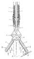
図1と図2は、本発明の第1の実施の形態の内視鏡用鋏型高周波切開具の先端部分の側面断面図と斜視図である。
1は、内視鏡の処置具案内管に挿脱自在な可撓性シースであり、ステンレス線を密着巻きしたコイルパイプにより形成されている。可撓性シース1の外周面には、電気絶縁性の可撓性チューブからなるシース外皮2が全長に被覆され、可撓性シース1の先端に固定的に取り付けられた先端口金3の外周にシース外皮2の先端が緊縛固定されている。4は、可撓性シース1内に緩く挿通された導電性の操作ワイヤーであり、可撓性シース1の基端に連結された操作部からの操作により、軸方向に進退させることができ、また軸周りに回転させることができる。Embodiments of the present invention will be specifically described below with reference to the drawings.
1 and 2 are a side sectional view and a perspective view of the distal end portion of the scissors-type high-frequency incision tool for an endoscope according to the first embodiment of the present invention.
Reference numeral 1 denotes a flexible sheath that can be inserted into and removed from a treatment instrument guide tube of an endoscope, and is formed of a coil pipe in which a stainless wire is tightly wound. The outer peripheral surface of the flexible sheath 1 is covered with the entire length of a sheath
5は、先端口金3に対して軸方向に移動することはできないが、軸周りに回転自在に先端口金3に連結された先端支持枠であり、先端支持枠5に形成されたスリット7の先端部分に、一対の高周波電極6A,6Bが支軸8を中心に回動自在に前方に向かって開閉自在に支持されている。9は、高周波電極6A,6Bを開閉駆動するための公知のリンク機構であり、操作ワイヤー4の先端がリンク機構9に連結されている。その結果、操作部において操作ワイヤー4を進退操作すれば高周波電極6A,6Bが支軸8を中心に開閉し、操作ワイヤー4を軸周りに回転操作すれば、先端支持枠5や高周波電極6A,6B等が一体となって先端口金3の軸周りに回転する。また、操作部側において操作ワイヤー4を高周波電源に接続することにより、操作ワイヤー4を経由して高周波電極6A,6Bに高周波電流を通電することができる。図1には、一対の高周波電極6A,6Bが開いた状態が示されているが、閉じた状態も二点鎖線で図示されている。なお、一対の高周波電極6A,6Bの開閉駆動をリンク機構9以外の機構で行ってもよい。
各高周波電極6A,6Bには、一対の高周波電極6A,6Bが閉じられた状態のときに互いに向かい合う位置(対向位置)に、一定の幅で対向方向に向かって突出する凸形の断面形状の直線状の電極刃部6bA,6bBが前後方向に真っ直ぐに形成されて、各高周波電極6A,6Bの電極刃部6bA,6bBの突端対向面のみに金属面が露出し(導電金属露出面6cA,6cB)、各高周波電極6A,6Bのその他の面には各々全面に一つながりに、例えばフッ素樹脂等のような化学的及び熱的に安定性が大きいいわゆる不活性の合成樹脂材からなる電気絶縁性コーティング皮膜10が被覆されている。電気絶縁性コーティング皮膜10部分は全図について砂目状に表示してある。このようにして電極刃部6bA,6bBの導電金属露出面6cA,6cBのみが金属露出面になっていることにより、粘膜剥離処置の際に切開が必要な生体組織だけを安全に高周波切開することができる。 Each of the high-
一対の高周波電極6A,6Bのうち第1の高周波電極6Aの最先端部分には、その高周波電極6Aの先端領域6aAを電気絶縁してさらにそこから第2の高周波電極6Bの先端領域6aBの前方位置に突出するように、第1の高周波電極6Aの長手方向に対して略垂直方向にL型に突出する絶縁突起6xが設けられている。絶縁突起6xは、図1に二点鎖線で示されるように一対の高周波電極6A,6Bが閉じた状態を前方(図1において左方)から見たときに、第1の高周波電極6Aの導電金属露出面6cAだけでなく第2の高周波電極6Bの導電金属露出面6cBが絶縁突起6xの背後に隠れる大きさに形成されていて、絶縁突起6xの全面が電気絶縁性コーティング皮膜10で被覆されている。 Of the pair of high-
その結果、本発明の内視鏡用鋏型高周波切開具を内視鏡の処置具案内管に通して粘膜下層剥離術を行う際に、図3に示されるように、一対の高周波電極6A,6Bの最先端部分が粘膜下の筋層30に触れる状態で一対の高周波電極6A,6Bに高周波電流が通電されても、絶縁突起6xが導電金属露出面6cA,6cBの前方に位置していることにより導電金属露出面6cA,6cBが筋層30に触れないので、筋層30が高周波焼灼されて損傷する恐れがなく、筋状繊維31だけを焼灼切断して粘膜下層剥離術を安全に行うことができる。また、粘膜下層剥離術を行うに際して、図4に示されるように、絶縁突起6xを筋状繊維31に引っかけて内視鏡20を湾曲操作等で首振り動作させることで、筋状繊維31を滑ることなく容易にたぐり寄せることができる効果もある。21は処置具案内管である。 As a result, when the submucosal dissection is performed by passing the scissors-type high-frequency incision instrument for endoscope of the present invention through the treatment instrument guide tube of the endoscope, as shown in FIG. Even when a high-frequency current is applied to the pair of high-
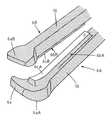
図5と図6は、本発明の第2の実施の形態の内視鏡用鋏型高周波切開具の先端部分の側面断面図と斜視図であり、絶縁突起6xが側方から見たとき前方に向かって凸の略円弧状に形成されている。その結果、第1の実施の形態と同様の効果に加えて、図5に示されるように、絶縁突起6xが生体組織の表面に押し付けられた状態で移動する際に生体組織に食い込むことなく生体組織の表面に沿ってスムーズに移動し易いメリットがある。また、この実施の形態においては、各高周波電極6A,6Bの電極刃部6bA,6bBを横切る電極横断溝6eA,6eBが複数形成されていて、その電極横断溝6eA,6eBにも電気絶縁性コーティング皮膜10が他の部分とつながった状態に被覆され、それによって電気絶縁性コーティング皮膜10の耐剥離強度が大きくされている。その他の構成は前記の第1の実施の形態と同様である。 5 and 6 are a side sectional view and a perspective view of the distal end portion of the scissors-type high-frequency incision tool for endoscope according to the second embodiment of the present invention, and the front side when the
図7は、本発明の第3の実施の形態の内視鏡用鋏型高周波切開具の先端部分の斜視図であり、各高周波電極6A,6Bの先端領域6aA,6aBの幅と絶縁突起6xの幅を、それより後方の各高周波電極6A,6Bの幅より幅広に形成したものである。その他の構成は前記の第1の実施の形態と同様である。このように構成することにより、第1の実施の形態と同様の効果に加えて、切開済みの粘膜が切開部に覆いかぶさるのを各先端領域6aA,6aBの幅広部で押し退けて、切開部を内視鏡観察し易い状態で粘膜下層剥離術を行うことができる効果がある。 FIG. 7 is a perspective view of the distal end portion of the scissors-type high-frequency incision tool for an endoscope according to the third embodiment of the present invention. The widths of the distal end regions 6aA and 6aB of the respective high-
図8は、本発明の第4の実施の形態の内視鏡用鋏型高周波切開具の先端部分の斜視図であり、絶縁突起6xを略球状に形成したものである。その他の構成は前記の第1の実施の形態と同様である。このように構成すると、第1の実施の形態と同様の効果に加えて、絶縁突起6xで粘膜をスムーズに押し広げることができる効果がある。なお、球状以外の形状で絶縁突起6x部分をそれ以外の部分の高周波電極6A,6Bの幅より幅広に形成してもよい。 FIG. 8 is a perspective view of the distal end portion of the scissors-type high-frequency incision tool for an endoscope according to the fourth embodiment of the present invention, in which the insulating
図9、図10及び図11は、本発明の第5の実施の形態の内視鏡用鋏型高周波切開具の先端部分の側面断面図、平面図及び斜視図であり、絶縁突起6xが形成されていない第2の高周波電極6Bの導電金属露出面6cBの先端部分を、先側ほど第1の高周波電極6から遠ざかるカーブ状の形状に形成すると共に、絶縁突起6xが形成されている第1の高周波電極6Aの導電金属露出面6cAの先端部分を、第2の高周波電極6Bの導電金属露出面6cBに沿うカーブ状の形状に形成して、そのカーブに沿うカーブ状に絶縁突起6xを第1の高周波電極6Aから突出形成したものである。このような形状に構成することにより、第1の実施の形態の効果に加えて、一対の高周波電極6A,6Bで微小血管や出血源を摘み易くなるメリットがある。なお、各高周波電極6A,6Bの先端領域6aA,6aBは第3の実施の形態と同様に幅広に形成してある。 9, 10, and 11 are a side sectional view, a plan view, and a perspective view of the distal end portion of the scissors-type high-frequency incision tool for endoscope according to the fifth embodiment of the present invention, and an insulating
また、この実施の形態においては、図9のA−A線における断面を図示する図12に示されるように、高周波電極6Aの導電金属露出面6cAより僅かに低い位置に導電金属露出面6cAの両側に平面部6dAが形成されている。第2の高周波電極6B側も同様である。その結果、図13に示されるように、切開部位の周囲の組織を一対の高周波電極6A,6Bの平面部6dA,6dBで挟み付けて固定したり、血管を圧迫して血流を遮断することができ、導電金属露出面6cA,6cBにおいて安定した状態で焼灼、切開処置を行うことができる。 Further, in this embodiment, as shown in FIG. 12 illustrating a cross section taken along the line AA of FIG. 9, the conductive metal exposed surface 6cA is positioned slightly lower than the conductive metal exposed surface 6cA of the
図14は、本発明の第6の実施の形態の内視鏡用鋏型高周波切開具の先端部分の斜視図であり、絶縁突起6xA,6xBを、第1の高周波電極6Aと第2の高周波電極6Bの各々の最先端部分の異なる半幅位置に各々形成したものである。その他の構成は前記の第1の実施の形態と同様である。このように、絶縁突起6xA,6xBを各高周波電極6A,6Bから突出形成することにより、第1の実施の形態と同様の効果に加えて、図15に示されるように、粘膜等を必要に応じて絶縁突起6xA,6xBで挟み付けて把持することができる。 FIG. 14 is a perspective view of the distal end portion of the scissors-type high-frequency incision tool for an endoscope according to the sixth embodiment of the present invention. Each of the
なお、本発明は各実施の形態の構成に限定されるものではなく、例えば電極刃部6bA,6bBが直線状でなくてもよく、その幅が全体に一定でなくてもよい。また、第1と第2の高周波電極6A,6Bの間を電気絶縁して、高周波電源の正極と負極とに分けて接続するいわゆるバイポーラ型の内視鏡用鋏型高周波切開具に適用することもできる。 In addition, this invention is not limited to the structure of each embodiment, For example, electrode blade part 6bA, 6bB may not be linear, and the width | variety may not be constant on the whole. The first and second high-
1…可撓性シース
2…シース外皮
4…操作ワイヤー
6A,6B…高周波電極
6aA,6aB…先端領域
6bA,6bB…電極刃部
6cA,6cB…導電金属露出面
6x,6xA,6xB…絶縁突起
8…支軸
10…電気絶縁性コーティング皮膜DESCRIPTION OF SYMBOLS 1 ...
Claims (8)
Translated fromJapanese前記一対の高周波電極の各々の対向面のみに前記導電金属を露出させて他の部分の表面を電気絶縁すると共に、前記一対の高周波電極のうち一方の高周波電極を直線状に形成し、他方の高周波電極を前記一方の高周波電極に沿って直線状に延びると共に前記一方の高周波電極の先端部を絶縁突起により覆う形状に形成し、前記一対の高周波電極が閉じた状態を前方からみたとき、前記一方の高周波電極の導電金属露出面が前記絶縁突起の背後に隠れる状態に位置させることを特徴とする内視鏡用鋏型高周波切開具。In a scissors-type high-frequency incision tool for an endoscope provided with a pair of high-frequency electrodes made of a conductive metal that opens and closes forward at the distal end of a sheath inserted into and removed from the treatment instrument guide tube of the endoscope,
The conductive metal is exposed only on the opposing surface of each of the pair of high-frequency electrodes to electrically insulate the surface of the other portion, and one high-frequency electrode of the pair of high-frequency electrodesis formed linearly, When the high-frequency electrode extends linearly along the one high-frequency electrode and has a shape in which the tip of the one high-frequency electrode is covered with an insulating protrusion, the closed state of the pair of high-frequency electrodes is viewed from the front,A scissors-type high-frequency incision tool for an endoscope, wherein the conductive metal exposed surface ofone of the high-frequency electrodes is positioned soas to be hidden behind the insulating protrusion.
Priority Applications (1)
| Application Number | Priority Date | Filing Date | Title |
|---|---|---|---|
| JP2006188593AJP4543017B2 (en) | 2006-06-12 | 2006-06-12 | Endoscopic high-frequency incision tool |
Applications Claiming Priority (1)
| Application Number | Priority Date | Filing Date | Title |
|---|---|---|---|
| JP2006188593AJP4543017B2 (en) | 2006-06-12 | 2006-06-12 | Endoscopic high-frequency incision tool |
Publications (2)
| Publication Number | Publication Date |
|---|---|
| JP2007330723A JP2007330723A (en) | 2007-12-27 |
| JP4543017B2true JP4543017B2 (en) | 2010-09-15 |
Family
ID=38930738
Family Applications (1)
| Application Number | Title | Priority Date | Filing Date |
|---|---|---|---|
| JP2006188593AActiveJP4543017B2 (en) | 2006-06-12 | 2006-06-12 | Endoscopic high-frequency incision tool |
Country Status (1)
| Country | Link |
|---|---|
| JP (1) | JP4543017B2 (en) |
Cited By (1)
| Publication number | Priority date | Publication date | Assignee | Title |
|---|---|---|---|---|
| CN105073048A (en)* | 2013-03-29 | 2015-11-18 | 奥林巴斯株式会社 | High-frequency treatment tool |
Families Citing this family (9)
| Publication number | Priority date | Publication date | Assignee | Title |
|---|---|---|---|---|
| JP5403959B2 (en)* | 2008-07-08 | 2014-01-29 | オリンパスメディカルシステムズ株式会社 | High frequency treatment tool |
| JP2012019846A (en)* | 2010-07-13 | 2012-02-02 | River Seiko:Kk | High frequency hemostatic forceps for endoscope |
| JP5535862B2 (en)* | 2010-10-12 | 2014-07-02 | 株式会社リバーセイコー | High frequency peeling knife device for endoscope |
| CN103354736B (en)* | 2011-03-09 | 2015-08-19 | 奥林巴斯医疗株式会社 | bipolar treatment device |
| JP6798100B2 (en)* | 2014-10-30 | 2020-12-09 | 住友ベークライト株式会社 | High frequency treatment tool for endoscopes |
| JP6763128B2 (en)* | 2014-10-29 | 2020-09-30 | 住友ベークライト株式会社 | Endoscopic scissors |
| BR112017007856A2 (en)* | 2014-10-29 | 2017-12-26 | Sumitomo Bakelite Co | endoscopic scissors and high frequency endoscopic treatment tool |
| JP6216482B1 (en)* | 2016-02-02 | 2017-10-18 | オリンパス株式会社 | Endoscopic treatment tool |
| JP6988287B2 (en)* | 2017-09-11 | 2022-01-05 | 住友ベークライト株式会社 | Knife for high frequency treatment tool and high frequency treatment tool for medical use |
Family Cites Families (6)
| Publication number | Priority date | Publication date | Assignee | Title |
|---|---|---|---|---|
| US5403312A (en)* | 1993-07-22 | 1995-04-04 | Ethicon, Inc. | Electrosurgical hemostatic device |
| JPH1024051A (en)* | 1995-09-20 | 1998-01-27 | Olympus Optical Co Ltd | Coagulation forceps with separating function |
| JP2000139943A (en)* | 1998-09-02 | 2000-05-23 | Olympus Optical Co Ltd | High-frequency treating instrument |
| JPH11267132A (en)* | 1998-01-23 | 1999-10-05 | Olympus Optical Co Ltd | High-frequency treatment tool |
| JP2001170069A (en)* | 1999-12-17 | 2001-06-26 | Olympus Optical Co Ltd | Medical treatment instrument |
| JP2004229976A (en)* | 2003-01-31 | 2004-08-19 | Nippon Zeon Co Ltd | Forceps type electric treatment instrument |
- 2006
- 2006-06-12JPJP2006188593Apatent/JP4543017B2/enactiveActive
Cited By (1)
| Publication number | Priority date | Publication date | Assignee | Title |
|---|---|---|---|---|
| CN105073048A (en)* | 2013-03-29 | 2015-11-18 | 奥林巴斯株式会社 | High-frequency treatment tool |
Also Published As
| Publication number | Publication date |
|---|---|
| JP2007330723A (en) | 2007-12-27 |
Similar Documents
| Publication | Publication Date | Title |
|---|---|---|
| JP4543017B2 (en) | Endoscopic high-frequency incision tool | |
| JP5636449B2 (en) | High frequency treatment tool | |
| JP4546424B2 (en) | Endoscopic treatment tool | |
| JP4555996B2 (en) | Endoscopic high-frequency incision tool | |
| WO2016068204A1 (en) | Endoscope scissors and endoscopic high-frequency treatment tool | |
| JP2002253570A (en) | Bipolar high frequency treatment tool for endoscope | |
| JP2010017574A (en) | High-frequency incision tool for endoscope | |
| JP4726015B2 (en) | Endoscopic high-frequency treatment instrument for endoscope | |
| US20220273329A1 (en) | Endoscopic surgical tool | |
| JP2013138844A (en) | High frequency cautery dissection scissors device for endoscope | |
| JP2003299667A (en) | Bipolar high-frequency incision instrument for endoscope | |
| JP4524476B2 (en) | Endoscopic high-frequency treatment instrument for endoscope | |
| JP4556000B2 (en) | Endoscopic monopolar high-frequency cage | |
| JP2011212315A (en) | High frequency treatment instrument for endoscope | |
| JP4726014B2 (en) | Endoscopic high-frequency treatment instrument for endoscope | |
| JP4524475B2 (en) | Endoscopic high-frequency treatment instrument for endoscope | |
| CN107613894A (en) | Disposal utensils | |
| JP4423474B2 (en) | End of the forceps for endoscope | |
| JP4461206B2 (en) | Endoscopic high-frequency incision tool | |
| JP2012075805A (en) | High frequency scissors for endoscope | |
| JP4296141B2 (en) | Endoscopic high-frequency treatment instrument | |
| JP6841029B2 (en) | Medical high frequency treatment tool | |
| JP4725808B2 (en) | Endoscopic hook-type high-frequency treatment instrument | |
| JP4476229B2 (en) | Bipolar saddle-shaped high-frequency treatment instrument for endoscope | |
| JP4283746B2 (en) | Endoscopic high-frequency treatment instrument |
Legal Events
| Date | Code | Title | Description |
|---|---|---|---|
| A621 | Written request for application examination | Free format text:JAPANESE INTERMEDIATE CODE: A621 Effective date:20090416 | |
| RD02 | Notification of acceptance of power of attorney | Free format text:JAPANESE INTERMEDIATE CODE: A7422 Effective date:20090729 | |
| A977 | Report on retrieval | Free format text:JAPANESE INTERMEDIATE CODE: A971007 Effective date:20100114 | |
| A131 | Notification of reasons for refusal | Free format text:JAPANESE INTERMEDIATE CODE: A131 Effective date:20100209 | |
| A521 | Request for written amendment filed | Free format text:JAPANESE INTERMEDIATE CODE: A523 Effective date:20100228 | |
| A131 | Notification of reasons for refusal | Free format text:JAPANESE INTERMEDIATE CODE: A131 Effective date:20100329 | |
| A521 | Request for written amendment filed | Free format text:JAPANESE INTERMEDIATE CODE: A523 Effective date:20100512 | |
| TRDD | Decision of grant or rejection written | ||
| A01 | Written decision to grant a patent or to grant a registration (utility model) | Free format text:JAPANESE INTERMEDIATE CODE: A01 Effective date:20100622 | |
| A01 | Written decision to grant a patent or to grant a registration (utility model) | Free format text:JAPANESE INTERMEDIATE CODE: A01 | |
| A61 | First payment of annual fees (during grant procedure) | Free format text:JAPANESE INTERMEDIATE CODE: A61 Effective date:20100628 | |
| R150 | Certificate of patent or registration of utility model | Ref document number:4543017 Country of ref document:JP Free format text:JAPANESE INTERMEDIATE CODE: R150 | |
| FPAY | Renewal fee payment (event date is renewal date of database) | Free format text:PAYMENT UNTIL: 20130702 Year of fee payment:3 | |
| R250 | Receipt of annual fees | Free format text:JAPANESE INTERMEDIATE CODE: R250 | |
| S533 | Written request for registration of change of name | Free format text:JAPANESE INTERMEDIATE CODE: R313533 | |
| S111 | Request for change of ownership or part of ownership | Free format text:JAPANESE INTERMEDIATE CODE: R313114 | |
| S111 | Request for change of ownership or part of ownership | Free format text:JAPANESE INTERMEDIATE CODE: R313114 | |
| S533 | Written request for registration of change of name | Free format text:JAPANESE INTERMEDIATE CODE: R313533 | |
| R350 | Written notification of registration of transfer | Free format text:JAPANESE INTERMEDIATE CODE: R350 | |
| R250 | Receipt of annual fees | Free format text:JAPANESE INTERMEDIATE CODE: R250 | |
| R250 | Receipt of annual fees | Free format text:JAPANESE INTERMEDIATE CODE: R250 | |
| R250 | Receipt of annual fees | Free format text:JAPANESE INTERMEDIATE CODE: R250 | |
| R250 | Receipt of annual fees | Free format text:JAPANESE INTERMEDIATE CODE: R250 | |
| R250 | Receipt of annual fees | Free format text:JAPANESE INTERMEDIATE CODE: R250 | |
| R250 | Receipt of annual fees | Free format text:JAPANESE INTERMEDIATE CODE: R250 | |
| R250 | Receipt of annual fees | Free format text:JAPANESE INTERMEDIATE CODE: R250 | |
| S531 | Written request for registration of change of domicile | Free format text:JAPANESE INTERMEDIATE CODE: R313531 | |
| S533 | Written request for registration of change of name | Free format text:JAPANESE INTERMEDIATE CODE: R313533 | |
| R360 | Written notification for declining of transfer of rights | Free format text:JAPANESE INTERMEDIATE CODE: R360 | |
| R360 | Written notification for declining of transfer of rights | Free format text:JAPANESE INTERMEDIATE CODE: R360 | |
| R360 | Written notification for declining of transfer of rights | Free format text:JAPANESE INTERMEDIATE CODE: R360 | |
| R371 | Transfer withdrawn | Free format text:JAPANESE INTERMEDIATE CODE: R371 | |
| R250 | Receipt of annual fees | Free format text:JAPANESE INTERMEDIATE CODE: R250 | |
| R250 | Receipt of annual fees | Free format text:JAPANESE INTERMEDIATE CODE: R250 | |
| R250 | Receipt of annual fees | Free format text:JAPANESE INTERMEDIATE CODE: R250 | |
| R250 | Receipt of annual fees | Free format text:JAPANESE INTERMEDIATE CODE: R250 | |
| R250 | Receipt of annual fees | Free format text:JAPANESE INTERMEDIATE CODE: R250 |