JP4541792B2 - Valve guide for rocker arm assembly - Google Patents
Valve guide for rocker arm assemblyDownload PDFInfo
- Publication number
- JP4541792B2 JP4541792B2JP2004215342AJP2004215342AJP4541792B2JP 4541792 B2JP4541792 B2JP 4541792B2JP 2004215342 AJP2004215342 AJP 2004215342AJP 2004215342 AJP2004215342 AJP 2004215342AJP 4541792 B2JP4541792 B2JP 4541792B2
- Authority
- JP
- Japan
- Prior art keywords
- rocker arm
- side walls
- arm assembly
- clip
- pin
- Prior art date
- Legal status (The legal status is an assumption and is not a legal conclusion. Google has not performed a legal analysis and makes no representation as to the accuracy of the status listed.)
- Expired - Fee Related
Links
Images


Classifications
- F—MECHANICAL ENGINEERING; LIGHTING; HEATING; WEAPONS; BLASTING
- F01—MACHINES OR ENGINES IN GENERAL; ENGINE PLANTS IN GENERAL; STEAM ENGINES
- F01L—CYCLICALLY OPERATING VALVES FOR MACHINES OR ENGINES
- F01L1/00—Valve-gear or valve arrangements, e.g. lift-valve gear
- F01L1/12—Transmitting gear between valve drive and valve
- F01L1/18—Rocking arms or levers
- F01L1/185—Overhead end-pivot rocking arms
- F—MECHANICAL ENGINEERING; LIGHTING; HEATING; WEAPONS; BLASTING
- F01—MACHINES OR ENGINES IN GENERAL; ENGINE PLANTS IN GENERAL; STEAM ENGINES
- F01L—CYCLICALLY OPERATING VALVES FOR MACHINES OR ENGINES
- F01L1/00—Valve-gear or valve arrangements, e.g. lift-valve gear
- F01L1/12—Transmitting gear between valve drive and valve
- F01L1/18—Rocking arms or levers
- F01L2001/187—Clips, e.g. for retaining rocker arm on pivot
- Y—GENERAL TAGGING OF NEW TECHNOLOGICAL DEVELOPMENTS; GENERAL TAGGING OF CROSS-SECTIONAL TECHNOLOGIES SPANNING OVER SEVERAL SECTIONS OF THE IPC; TECHNICAL SUBJECTS COVERED BY FORMER USPC CROSS-REFERENCE ART COLLECTIONS [XRACs] AND DIGESTS
- Y10—TECHNICAL SUBJECTS COVERED BY FORMER USPC
- Y10T—TECHNICAL SUBJECTS COVERED BY FORMER US CLASSIFICATION
- Y10T74/00—Machine element or mechanism
- Y10T74/21—Elements
- Y10T74/2101—Cams
- Y10T74/2107—Follower
Landscapes
- Engineering & Computer Science (AREA)
- Mechanical Engineering (AREA)
- General Engineering & Computer Science (AREA)
- Valve-Gear Or Valve Arrangements (AREA)
- Jigs For Machine Tools (AREA)
- Clamps And Clips (AREA)
- Load-Engaging Elements For Cranes (AREA)
Abstract
Description
Translated fromJapanese本発明は、内燃エンジン用のバルブ制御システムに関し、特に、このシステムで使用される改良されたロッカーアームアセンブリに関する。 The present invention relates to a valve control system for an internal combustion engine, and more particularly to an improved rocker arm assembly for use in this system.
エンジンのポペットバルブ用バルブ制御システムが当該技術において一般に周知である。本発明は、オーバーヘッドカム(OHC)型のバルブ制御システムでの使用に、これに限定されるわけではないが、特に適しており、OHC型のバルブ制御システムに関して説明する。代表的なOHC型のバルブ制御システムでは、制御されるエンジン用ポペットバルブに加えて、ロッカーアームアセンブリと、ロッカーアームアセンブリのピボット運動の中心となるある種の「支点」機構が設けられている。さらに、OHC型のバルブ制御システムは、カムプロフィールを定めるカム軸を有し、ロッカーアームアセンブリは、ロッカーアームアセンブリに対して固定されている軸を中心に回転可能に設けられ、その軸上に支持されているローラフォロワ部材などのカムフォロワを有している。 Valve control systems for engine poppet valves are generally well known in the art. The present invention is not particularly limited for use in an overhead cam (OHC) type valve control system, but will be described with respect to an OHC type valve control system. In a typical OHC type valve control system, in addition to the engine poppet valve to be controlled, there is a rocker arm assembly and some sort of "fulcrum" mechanism that is central to the pivoting motion of the rocker arm assembly. Further, the OHC type valve control system has a cam shaft that defines a cam profile, and the rocker arm assembly is rotatably provided about and supported on a shaft fixed to the rocker arm assembly. And a cam follower such as a roller follower member.
通常、本発明が関連している種類のロッカーアームアセンブリは、エンジンポペットバルブのバルブステムの上部の先端部分と係合する、一体に形成されたバルブステム先端のパッド部分を有している。最近の傾向は、そのような一体化されたバルブステム先端のパッド部分から、パッドとバルブステムの先端部分との間の摺動による係合なしに、バルブステムの先端部分と係合可能な回転可能な(ピボット運動可能な)パッド部分を使用することに移行している。たとえば、特許文献1は、バルブステム先端のパッド部分の、多数のさまざまな構成の種類と取り付けのための構造を示している。この特許文献に示されている様々なパッド部分の構成の中で、いくつかは「切り欠き付きの丸太」の形式であり、つまり、これらは、全体構成は概ね円柱形であるが、1つまたは複数の平面を定めている切り欠きが中心に向けて形成されていて、切り欠きの1つは特にバルブステムの先端部分の端面に係合するように作られている。したがって、添付の特許請求の範囲に示されている場合を除き、本発明は、バルブステム先端のパッド部分のこの特定の構成や、その他のどのような特定の構成にも限定されるものではないが、「切り欠き付きの丸太」の構成は、1つの好適な実施形態を表していて、本発明を、その構成に関連して説明する。 Typically, a rocker arm assembly of the type to which the present invention relates has an integrally formed valve stem tip pad portion that engages an upper tip portion of the valve stem of an engine poppet valve. A recent trend has been to rotate from such an integrated valve stem tip pad portion into a valve stem tip portion without sliding engagement between the pad and the valve stem tip portion. There is a shift to using possible (pivotable) pad portions. For example, Patent Literature 1 shows a number of various types of configurations and structures for mounting the pad portion at the tip of the valve stem. Among the various pad portion configurations shown in this patent document, some are in the form of "notched logs", that is, they are generally cylindrical in shape, but one Alternatively, a notch defining a plurality of planes is formed toward the center, and one of the notches is particularly designed to engage the end face of the tip portion of the valve stem. Accordingly, the invention is not limited to this particular configuration of the pad portion at the tip of the valve stem, or any other specific configuration, except as set forth in the appended claims. However, the “notched log” configuration represents one preferred embodiment and the present invention will be described in relation to that configuration.
内燃エンジンのポペットバルブ用バルブの制御システムの多くは、従来の固定(つまり、バルブリフトを変更する機能、または、エンジンのポペットバルブを「休止する」機能がない)形式であり、本発明を、このような「固定式」のバルブ制御システムに有利に使用することもできるが、本発明は、バルブ休止制御システムでの使用に特に適しており、バルブ休止制御システムに関連して説明する。バルブの休止を達成するために使用されるさまざまな構造は、本発明にとっては重要ではなく、また、特に本発明と関連してもいないため、本明細書では簡単に説明するが、本発明に関連している典型的なバルブ休止システムの1つの態様がある。典型的な「固定式」バルブ制御システムでは、ロッカーアームは、約10から20度のわずかな角度だけピボット運動を行うのに対して、典型的なバルブ休止システムでは、ロッカーアームアセンブリは、通常、25度もピボット運動を行う。
ロッカーアームの比較的広範囲のピボット運動を通して(バルブを休止する場合)、バルブステムの先端部分の端部の表面とロッカーアームのパッド部分との間の非摺動の係合を維持することが必要になるため、ロッカーアームアセンブリ内に、適切なバルブステムの先端のパッド部分を設けることと、パッド部分を取り付けて保持することが、幾分複雑になる。 It is necessary to maintain a non-sliding engagement between the end surface of the tip portion of the valve stem and the pad portion of the rocker arm through a relatively wide range of pivoting movement of the rocker arm (when the valve is at rest) Thus, providing a suitable valve stem tip pad portion within the rocker arm assembly and attaching and holding the pad portion is somewhat complicated.
当業者には周知のように、軸に取り付けられていて、ロッカーアームアセンブリに対して保持しなければならないカムフォロワが存在することに加えて、ロッカーアームアセンブリ内で保持しなければならない回転可能な(つまりピボット運動可能な)パッド部分を設けることは、ロッカーアームアセンブリ全体に含まれる部品の数を大幅に増加させる。パッド部分とカムフォロワの軸を保持しなければならないことは、ロッカーアームアセンブリの全製造費用を大幅に増加させ、特に、ロッカーアームを組み立てる時間と費用を増加させる。 As known to those skilled in the art, in addition to the presence of a cam follower that is attached to the shaft and must be held against the rocker arm assembly, it is rotatable that must be held within the rocker arm assembly ( Providing a pad portion (that is, pivotable) greatly increases the number of parts included in the entire rocker arm assembly. Having to hold the pad portion and the cam follower shaft greatly increases the overall manufacturing cost of the rocker arm assembly, and in particular increases the time and cost of assembling the rocker arm.
したがって、本発明の目的は、前述の従来技術の欠点を克服する、改良されたロッカーアームアセンブリを提供することである。 Accordingly, it is an object of the present invention to provide an improved rocker arm assembly that overcomes the aforementioned disadvantages of the prior art.
本発明の他の目的は、改良されたバルブステム先端パッド部分とその保持用機構を有している改良されたロッカーアームアセンブリを提供することである。 It is another object of the present invention to provide an improved rocker arm assembly having an improved valve stem tip pad portion and retention mechanism.
本発明のさらに他の目的は、ロッカーアームアセンブリの部品数を最少化し、ロッカーアームアセンブリの組み立て時間とコストを削減しつつ、前述の目的を達成する改良されたロッカーアームアセンブリを提供することである。 Yet another object of the present invention is to provide an improved rocker arm assembly that achieves the foregoing objects while minimizing the number of parts of the rocker arm assembly and reducing the assembly time and cost of the rocker arm assembly. .
本発明の前述の目的とその他の目的は、シリンダヘッドと、カムプロフィールを定めているカム軸の回転に応答して、シリンダヘッドと相対的に、開いた位置と閉じた位置との間を移動可能なポペットバルブを有している、内燃エンジン用のバルブ制御システムで使用されるロッカーアームアセンブリの提供により達成される。バルブ制御システムは、実質的に、シリンダヘッドに対して固定されていて、支点部分を有している支点装置をさらに備えている。ロッカーアームアセンブリは、支点部分に係合する支点用表面を定めている部分により相互に接続されている、軸方向に離れている1対の側壁を有しているロッカーアームを有しており、それによってロッカーアームアセンブリはポペットバルブが開いた位置と閉じた位置との間を移動するときに支点部分を中心としてピボット運動をする。ロッカーアームアセンブリは、両方の側壁の間に設けられていて、カムプロフィールと係合し、ロッカーアームの両方の側壁により定まる両方の軸用開口の中に延びている取り付け用軸を中心として設けられているカムフォロワをさらに有している。ロッカーアームアセンブリは、ポペットバルブのバルブステムの先端部分と係合するバルブパッドを定めていて、ロッカーアームの両方の側壁により定まる両方のピン用開口中に延びているピン部材も有している。最後に、ロッカーアームアセンブリはクリップ部材も有している。 The foregoing and other objects of the present invention are to move between an open position and a closed position relative to the cylinder head in response to rotation of the cylinder head and the camshaft defining the cam profile. This is achieved by providing a rocker arm assembly for use in a valve control system for an internal combustion engine having a possible poppet valve. The valve control system further comprises a fulcrum device substantially fixed to the cylinder head and having a fulcrum portion. The rocker arm assembly has a rocker arm having a pair of axially spaced sidewalls interconnected by portions defining a fulcrum surface that engages the fulcrum portion; The rocker arm assembly thereby pivots about the fulcrum portion as the poppet valve moves between the open and closed positions. The rocker arm assembly is provided between both side walls and engages the cam profile and is centered about a mounting shaft extending into both axial openings defined by both side walls of the rocker arm. It further has a cam follower. The rocker arm assembly defines a valve pad that engages the tip portion of the valve stem of the poppet valve and also has a pin member that extends into both pin openings defined by both side walls of the rocker arm. Finally, the rocker arm assembly also has a clip member.
改良されたロッカーアームアセンブリは、クリップ部材が、ロッカーアームの両方の側壁に隣接してその外側に設けられていて、軸方向に離れている1対のクリップ側壁と、両方のクリップ側壁を相互に接続している接続部分を有していることを特徴としている。両方のクリップ側壁は、取り付け用軸とピン部材の、両方の軸方向動きを抑制するように設けられている。両方のクリップ側壁の1つは、ロッカーアームの隣接している側壁と係合していて、ロッカーアームの両方の側壁の間に延びている第1の保持用部分であって、ピン部材に隣接して設けられていて、ピン部材がロッカーアームに相対的に、ピン部材の軸を中心に回転するのを制限している末端部分を含む第1の保持用部分を有している。 The improved rocker arm assembly includes a pair of clip sidewalls that are spaced axially apart from each other with a clip member disposed adjacent to and adjacent to both sidewalls of the rocker arm, and both clip sidewalls to each other. It has the connection part which has connected, It is characterized by the above-mentioned. Both clip sidewalls are provided to restrain both axial movements of the mounting shaft and the pin member. One of both clip sidewalls is a first retaining portion that engages an adjacent sidewall of the rocker arm and extends between both sidewalls of the rocker arm, adjacent to the pin member And a first retaining portion including a distal portion that restricts the pin member from rotating about the axis of the pin member relative to the rocker arm.
次に、本発明の実施の形態について図面を参照して説明する。 Next, embodiments of the present invention will be described with reference to the drawings.
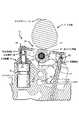
ここで、本発明を限定することを意図していない図面を参照すると、図1は、本発明のロッカーアームアセンブリを使用可能な、オーバーヘッドカム(OHC)型の内燃エンジンのシリンダヘッド11の部分を示している。図1は、全体に番号13が付けられていて、エンジン用ポペットバルブ15の運動(「リフト」)の制御に使用される従来のバルブ制御システムを示している。エンジンポペットバルブ15は、先端部分17(本明細書では「バルブステム先端部分」とも呼ぶ)を有している。当業者には周知のように、先端部分17は通常、バルブ戻しばね(簡単化のために本明細書では不図示)の上端の座面の役割を有しているばね受け(本明細書では不図示)により囲まれている。 Referring now to the drawings that are not intended to limit the present invention, FIG. 1 illustrates a portion of a
バルブ制御システム13は、全体に番号19が付けられているカム軸と連動して、バルブ戻しばねの偏倚させる(閉じる)力に抗して、エンジンポペットバルブ15を周期的に開く動作を行なう。当業者には周知のように、カム軸19は、基部の円形部分21と、バルブリフト部分23を有している。 The
従来技術である図1に示しているように、従来のバルブ制御システム13は、かなり従来型の、典型的には打ち抜き加工されたロッカーアーム27を有していて、全体に番号25が付けられているロッカーアームアセンブリを有している。従来技術と本発明の両方で対象としている、単なる例としての実施形態では、ロッカーアーム27は、下方に向かって開いた、概ねU字形の部材を有している。ロッカーアームアセンブリ25は、軸31を中心に回転可能に取り付けられているカムフォロワ(ローラ)29を、ロッカーアームアセンブリ25内で相対的に回転可能なように、保持している。 As shown in prior art FIG. 1, a conventional
ロッカーアームアセンブリ25の右端(図1で見て)には、番号33が付けられていて、当該技術分野では現在周知で、ポペットバルブ15のバルブステムの先端部分17の端面に係合している、三角形の、バルブステムの先端用のパッド部分(以降では、単にパッド部分と呼ぶ)が設けられている。ロッカーアームアセンブリ25の軸方向の反対側の端では、ロッカーアーム27は、部分的に球形(つまり「ドーム状」)の部分35を定めていて、この部分35の下側は、全体に番号41が付けられている、油圧式ラッシュ補償装置(HLA)の球形プランジャの部分39と係合するように設けられている支点表面37を有している。OHC動バルブ歯車列技術の当業者には周知のように、ロッカーアームアセンブリ25のピボット運動の中心となる「支点部分」が通常、設けられている。対象としている、単なる例としての本実施形態では、HLA41は「支点部分」有しているが、必要な支点部分(つまりピボット部分)を提供するために、本発明の範囲内で、様々なその他の構造を含めることができることが理解されるべきである。 The right end (as viewed in FIG. 1) of the
単なる例としての実施形態では、「バルブ休止」技術の当業者に現在周知のように、HLA41は、内側のボディ部材43が、外側のボディ部材45に対して相対的に、ラッチされた状態またはラッチが解除された状態のいずれかになることができる、休止型のラッシュ補償装置である。また、当業者に周知のように、内側のボディ部材43のラッチが解除された状態は、外側のボディ部材45により形成されている環状溝47内に加圧された液体が存在することに応答して、通常発生する。環状溝47内の加圧された制御用液体は、全体に番号49が付けられていて、シリンダヘッド11内の離れた位置から与えられている制御圧力の供給源から送られる。制御圧力は次に、ラッチが解除された状態を達成するために、制御圧力の供給源49から液体用通路51を介して環状溝47に送られる。しかし、本発明の目的のためには、HLA41の休止の詳細も、HLA41の休止の存在さえも、必須の特徴ではないことが、理解されるべきである。 In an exemplary embodiment only, as is now well known to those skilled in the art of “valve deactivation”, the HLA 41 is either in a state where the
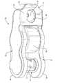
ここで、主に図2と3を参照して、本発明の、全体に番号55が付けられているロッカーアームアセンブリを説明する。ロッカーアームアセンブリ55は、本発明を実施する場合に、図1のバルブ制御システム13において、従来技術のロッカーアームアセンブリ25の代わりに使用されることが理解されるべきである。以降の説明では、図1の従来技術のロッカーアームアセンブリ25と同一か実質的に同一の部材には同じ参照番号が付けられることになる。ロッカーアームアセンブリ55は、通常、経済的な理由から、一体で、単一の、打ち抜き加工された部材を有していることが好ましいロッカーアーム57を有している。ロッカーアーム57は、下部が支点用表面37を定めている(図2参照)ドーム状の部分35を有している接続部分63により相互に接続されている(図3に最もわかりやすく示している)1対の側壁59と61を有している。前述のように、支点用表面37は、HLA41の球形プランジャ部分39と係合する。 Referring now mainly to FIGS. 2 and 3, a rocker arm assembly, generally designated 55, of the present invention will be described. It should be understood that the
図4で最もわかるように、ロッカーアームの側壁59と61は、カムフォロワ29が回転可能に取り付けられている軸31の対向する両端をそれぞれ受け入れて支持している、円形の軸用開口65をそれぞれ形成している。本発明の実施形態では、カムフォロワの軸31の軸方向の長さは、以下に明らかになる理由により、ロッカーアーム57の側壁59の外側表面から、ロッカーアーム57の側壁61の外側表面までの軸方向の距離に概ね等しい。多くの従来技術のロッカーアームアセンブリでは、フォロワ軸の軸方向の長さは、より長く、通常、保持部材(C形止め輪など)をフォロワ軸の各端部に取り付けるのに十分な長さとなろう。つまり、そのような構成は、適切な溝をフォロワ軸の各端部に形成すようなフォロワ軸の機械加工を必要とし、ロッカーアームアセンブリのコストをさらに増加させることになる。本発明は、前述した余分な機械加工と組み立て工程を実質的に不要とする。 As best seen in FIG. 4, the rocker
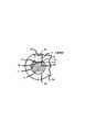
ここで、主として図2と5を参照して、図1の従来技術のパッド部分33の代わりに使用される、本発明によるバルブステム先端パッド部分について説明する。本発明のロッカーアームアセンブリ55は、図5と6に最もよくわかるように示しているように、両側壁59と61によって形成されて円形のピン用開口71内に回転可能におのおのが設けられている、対向している円柱形の1対の端部69を有しているピン部材67を有している。ピン部材67は、[背景技術]で説明した、概ね「切り欠き付きの丸太」の構成を有しており、したがって、(おのおのが、バルブステム先端部分17と係合する「パッド部分」を構成することができる)1対の平行で平らなパッド表面73を形成している。そのため、ピン部材67は「反転可能」、つまり、図2、3、5、および6に示している位置に取り付けるか、180度回転させることが可能で、当業者は、ピン部材67は直径方向で対向しているこれらの位置のいずれでも、同じように機能することを理解するであろう。さらに、本発明を、ピン部材67が平行な1対のパッド表面73を有している実施形態に関連して説明しているが、本発明はこの実施形態には限定されないことを、理解されるべきである。望むならば、単なる例として、ピン部材67は、1つのパッド表面73だけを有していたり、あるいはその代わりに、図1のパッド部分33について示しているものと同様に、3つのパッド表面73を有していたり、必要により、その他の任意の数のパッド表面73を有することもできる。 Referring now primarily to FIGS. 2 and 5, the valve stem tip pad portion according to the present invention used in place of the prior
軸31に関して説明したように、必須ではないが、ピン部材67は、後述する理由により、図4と5に最もわかりやすく示しているように、軸方向の長さが側壁59の外側表面から側壁61の外側表面までの距離に概ね等しいことが好ましい。やはり、公知の従来技術の装置の中には、ピン部材(つまりパッド部分)が、ピン部材の軸方向の各端部に(C形止め輪のような)何らかの種類の保持部材を使用できるように、両ロッカーアーム側壁の壁表面を越えてさらに十分遠くに延びているものもある。本発明はまた、前述した種類の追加の部品と組み立て体を実質的に不要とする。 As described with respect to the shaft 31, although not essential, the
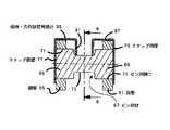
本発明の重要な態様によれば、ロッカーアームアセンブリ55は、クリップ部材75を有していて、図7に最もわかりやすく示しているように、クリップ部材75は、図2から6に示している形状に後で形成される、打ち抜き加工された部材からなることが好ましい。クリップ部材75は、本実施形態では、ロッカーアーム側壁59と61の外側表面にそれぞれ直接隣接して設けられている1対のクリップ側壁77と79を有している。当業者は、図4と5では、主に図示を簡単にするために、クリップ側壁77と79は、ロッカーアーム側壁59と61の外側表面にそれぞれ係合するものとして示されていることを理解すべきである。しかし、本発明の範囲内で、クリップ側壁77と79は、それぞれロッカーアーム側壁59と61の外側表面から、わずかに間をあけて設けることもできる。 In accordance with an important aspect of the present invention, the
クリップ側壁77と79は、図2と7にだけ完全に示している接続部分81により連結されており、接続部分81は、概ねU字の形状に折り曲げられて(図3も参照)、ロッカーアーム57の接続部分63に密着する保持用タブ83を有している。保持用タブ83は、クリップ部材75をロッカーアーム57に相対的に定位置に保持する役割を持つ構造の一部であることが、クリップ部材75の後の説明から理解されるであろう。保持機能を提供するそれ以外の構造については、後で説明する。この接続部分81は、球形プランジャの部分39の下側の切れ込みに長穴84の両側が係合するまで長穴84の両側をわずかに変形させることで、接続部分81が球形プランジャ部分39上で摺動する大きさの長穴84を定めている。その係合以降、球形プランジャ部分39とロッカーアームアセンブリ55は、バルブ制御システム13のシリンダヘッド11へのその後の組み付けに備えて、相互に前述の「組み立てられた」位置を維持する。 The
ここで、主に図3と5を参照すると、クリップ側壁77と79は、保持用タブ83に対して軸方向の反対側の端部に、保持・方向設定用部分85と87をそれぞれ有している。本発明には必須ではないが、保持・方向設定用部分85と87は、互いに実質的に同一である。ロッカーアームアセンブリ55の用途によっては、保持・方向設定用部分の一方だけ(85または87)を設けることで十分な場合もあるが、本実施形態では、両方が設けられていて、以降では、保持・方向設定用部分85だけについて説明するが、その説明は、保持・方向設定用部分87についても同様に当てはまることが理解されるべきである。 Referring mainly to FIGS. 3 and 5, the
図3、5、および6に最もわかりやすく示しているように、保持・方向設定用部分85は、ロッカーアーム側壁59の上部の表面に形成されている浅い切り欠き89内に入っている(図3と6を参照)。切り欠き89の内部への、この保持・方向設定用部分85の係合により、クリップ部材75のロッカーアーム57に対する保持が完全になる。保持・方向設定用部分85は、「内側に向かって」(つまり、図5の反対側のロッカーアーム側壁61に向かって)延びていて、バルブステムの先端部分17に係合する一方のパッド表面73ではなく、ピン部材67の「上部」寄りに設けられている他方のパッド表面73に向けて延びている末端部分91を有している。 As best shown in FIGS. 3, 5 and 6, the holding / orienting
図4と5に示しているように、本発明の重要な態様の1つにしたがって、クリップ側壁77と79は、それぞれ、ロッカーアーム側壁59と61に隣接していて、その外側に設けられることが好ましい。クリップ側壁77と79の配置は、その他の形態の保持手段を一切必要とせずに、また同様に重要なことであるが、カムフォロワ軸31やピン部材67へのC形止め輪の取り付けなどの特別な組み立て工程を一切必要とせずに、カムフォロワ軸31とピン部材67の軸方向動きを抑制する役割を本来有している。したがって、単純な、打ち抜き加工されたクリップ部材75により、カムフォロワ軸31とパッド部分33を保持するために、従来技術の装置で以前は必要であったあらゆる構造と組み立て時間が置き換えられる。クリップ側壁77と79は本明細書では、「完全な」壁として示されているが(図7を参照)、そのような完全な壁であることは、本発明にとって必須ではないことが理解されるべきである。望むならば、クリップ側壁77と79は、図の側壁77と79の領域のいくらかの部分、あるいは大部分に開口部分を有していてもよい。本発明に必須なことは、側壁77と79が、接続部分81を保持・方向設定用部分85と87に接続するために十分な「壁」を有していることと、カムフォロワ軸31とピン部材67を拘束(および保持)するために十分な「壁」を有していることだけである。 As shown in FIGS. 4 and 5, in accordance with one important aspect of the present invention,
図6にもっともわかりやすく示しているように、本発明の他の重要な態様にしたがって、末端部分91は、「上部」のパッド表面73(つまり、バルブステムの先端部分17に係合するパッド表面73とは反対側のパッド表面73)に隣接する位置まで延びている。末端部分91は、それぞれが、水平面に対して、また隣接するパッド表面73に対して、角度「A」を有するように設けられている1対の方向設定用表面93を有している。角度「A」は、ロッカーアームアセンブリ55の通常動作中は、ロッカーアームアセンブリ55のピボット運動の最大角度と概ね等しい(または、わずかに大きい)ことが好ましい。当業者には周知のように、ロッカーアームアセンブリ55は通常、ラッチが解除された(休止)状態で動作しているときには、より大きな角度の運動が与えられ、そのため、角度「A」は、ロッカーアームアセンブリ55が休止状態のときのピボット運動の角度に対応して選択しなければならない。 As best seen in FIG. 6, in accordance with another important aspect of the present invention, the
ロッカーアームアセンブリ55が組み立てられて、クリップ部材75がロッカーアーム57の周囲に取り付けられると、パッド表面73に隣接して設けられている方向設定用表面93は、ピン部材67の回転を、ロッカーアームアセンブリ55に対して角度「A」までの運動に制限することになる。その結果、ピン部材67は、ロッカーアームアセンブリ55がシリンダヘッド11に取り付けられるときに、「適切な向き」である角度「A」の範囲内に常にある。「適切な向き」とは、パッド表面73がバルブステムの先端部分17に係合するときに、パッド表面73とバルブステムの先端部分17の端面とが平行な面対面の係合になるまで、係合により、ピン部材67がわずかに回転して、これらの係合する表面同士がほぼ十分に並行になるような角度に、ピン部材67が向いていることを意味している。したがって、ロッカーアームアセンブリ55のシリンダヘッド11への組み付け時に、パッド表面73の、バルブステムの先端部分17の端面への適切な係合を達成するために、ピン部材67の方向を設定する別個の手順を設ける必要は全くなく、そのような係合は、本発明の結果により、本質的に発生するものである。 When the
11 シリンダヘッド
13 バルブ制御システム
15 ポペットバルブ
17 バルブステムの先端部分
19 カム軸
21 基部の円形部分
23 カムプロフィール
25 ロッカーアームアセンブリ
27 ロッカーアーム
29 カムフォロワ
31 カムフォロワ29の取り付け用軸
33 パッド部分
35 ドーム状の部分
37 支点用表面
39 プランジャの部分
41 油圧式ラッシュ補償装置(HLA)
43 内側のボディ部材
45 外側のボディ部材
47 環状溝
49 制御圧力の供給源
51 液体用通路
55 ロッカーアームアセンブリ
57 ロッカーアーム
59 ロッカーアーム57の側壁
61 ロッカーアーム57の側壁
63 接続部分
65 軸用開口
67 ピン部材
69 端部
71 ピン用開口
73 パッド表面
75 クリップ部材
77 クリップ側壁
79 クリップ側壁
81 接続部分
83 保持用タブ
84 長穴
85 保持・方向設定用部分
87 保持・方向設定用部分
89 切り欠き
91 末端部分
93 方向設定用表面DESCRIPTION OF
43
Claims (9)
Translated fromJapanese前記ポペットバルブ(15)が前記開いた位置と閉じた位置との間を移動するときに前記ロッカーアームアセンブリ(55)が前記支点部分を中心としてピボット運動をするように、前記支点部分(39)に係合する支点用表面(37)を定めている部分(63)により相互に接続され、ロッカーアーム(57)の回転軸方向に離れている1対の側壁(59、61)を有しているロッカーアーム(57)と、前記両側壁(59、61)の間に設けられて、前記カムプロフィール(23)と係合し、前記両側壁(59、61)により定まる両軸用開口(65)の中に延びている取り付け用軸(31)を中心として設けられているカムフォロワ(29)と、前記ポペットバルブ(15)のバルブステムの先端部分(17)と係合するバルブパッドを定めていて、前記両側壁(59、61)により定まる両ピン用開口(71)の中に延びているピン部材と、クリップ部材とを有するロッカーアームアセンブリ(55)において、
(a)前記クリップ部材(75)は、前記ロッカーアーム(57)の前記1対の側壁(59、61)に隣接して外側に設けられていて、前記ロッカーアーム(57)の回転軸方向に離れている1対のクリップ側壁(77、79)と、1対の前記クリップ側壁(77、79)を相互に接続する接続部分(81)とを有していること、
(b)前記クリップ側壁(77、79)は、前記取り付け用軸(31)と前記ピン部材(67)の両方の、前記ロッカーアーム(57)の回転軸方向の動きを抑制するように設けられていること、
(c)前記両クリップ側壁の一方(77)は、前記ロッカーアーム(57)の隣接している前記側壁(59)と係合していて、前記ロッカーアーム(57)の前記両側壁(59、61)の間を延びている第1の保持用部分(85)であって、前記ピン部材(67)に隣接して設けられていて、前記ピン部材(67)が前記ロッカーアーム(57)に相対的に、前記ピン部材(67)の軸を中心に回転するのを制限するように動作可能な末端部分(91)を含む第1の保持用部分(85)を有していること、
を特徴とするロッカーアームアセンブリ。Responsive to rotation of the cylinder head (11) and the cam shaft (19) defining the cam profile (23), the cylinder head (11) is movable between an open position and a closed position relative to the cylinder head. A valve control system for an internal combustion engine having a poppet valve (15), which ispivotally supported with respect to the cylinder head (11) and has a fulcrum part (39). A rocker arm assembly (55) for use in a valve control system comprising:
The fulcrum portion (39) so that the rocker arm assembly (55) pivots about the fulcrum portion as the poppet valve (15) moves between the open and closed positions. A pair of side walls (59, 61) which are connected to each other by a portion (63) defining a fulcrum surface (37) which engages with each other and are spaced apart in the direction ofthe rotation axisof the rocker arm (57) Provided between the rocker arm (57) and the both side walls (59, 61), which engages with the cam profile (23) and is defined by the both side walls (59, 61). ) And a valve pad that engages with the tip portion (17) of the valve stem of the poppet valve (15). Have determined, a pin member extending into both the pin opening defined by said side walls (59, 61) (71), the rocker arm assembly (55) having a clip member,
(A) The clip member (75) is provided on the outer side adjacent to the pair of side walls (59, 61) of therocker arm (57), and extends in the direction ofthe rotation axis of therocker arm (57). A pair of spaced clip side walls (77, 79) and a connecting portion (81) interconnecting the pair of clip side walls (77, 79);
(B) The clip side walls (77, 79) are provided so as to suppress movementof both the mounting shaft (31) and the pin member (67) inthe direction ofthe rotation axisof the rocker arm (57). That
(C) One of the clip side walls (77) is engaged with the side wall (59) adjacent to the rocker arm (57), and the both side walls (59, 59) of the rocker arm (57) are engaged. 61) is a first holding portion (85) extending between the pin member (67) and the pin member (67) to the rocker arm (57). Relatively having a first retaining portion (85) including a distal portion (91) operable to limit rotation about the axis of the pin member (67);
Rocker arm assembly characterized by.
前記両ピン用開口(71)は円形であり、
前記両ピン用開口(71)は、前記ピン部材(67)が前記両ピン用開口(71)内で自由に回転するように、前記ピン部材(67)の各端部(69)を内部に受け入れている、請求項1に記載のロッカーアームアセンブリ。The pin member (67) is entirelycylindrical ,
The both pin openings (71) are circular,
Both the pin openings (71) have the ends (69) of the pin members (67) inside so thatthe pin members (67) can freely rotate within the both pin openings (71). The rocker arm assembly of claim 1, wherein the rocker arm assembly is receiving.
Applications Claiming Priority (1)
| Application Number | Priority Date | Filing Date | Title |
|---|---|---|---|
| EP03254593AEP1500794B1 (en) | 2003-07-23 | 2003-07-23 | Metal sheet clip for rocker arm |
Publications (2)
| Publication Number | Publication Date |
|---|---|
| JP2005042725A JP2005042725A (en) | 2005-02-17 |
| JP4541792B2true JP4541792B2 (en) | 2010-09-08 |
Family
ID=33484033
Family Applications (1)
| Application Number | Title | Priority Date | Filing Date |
|---|---|---|---|
| JP2004215342AExpired - Fee RelatedJP4541792B2 (en) | 2003-07-23 | 2004-07-23 | Valve guide for rocker arm assembly |
Country Status (7)
| Country | Link |
|---|---|
| US (1) | US6889644B2 (en) |
| EP (1) | EP1500794B1 (en) |
| JP (1) | JP4541792B2 (en) |
| KR (1) | KR101119404B1 (en) |
| CN (1) | CN100392211C (en) |
| AT (1) | ATE384857T1 (en) |
| DE (1) | DE60318836T2 (en) |
Families Citing this family (36)
| Publication number | Priority date | Publication date | Assignee | Title |
|---|---|---|---|---|
| DE102004033973A1 (en)* | 2004-07-14 | 2006-02-16 | Ina-Schaeffler Kg | Connecting element for the captive mounting of a lever-like cam follower |
| JP4293167B2 (en)* | 2005-07-25 | 2009-07-08 | 三菱自動車工業株式会社 | Variable valve operating device for internal combustion engine |
| DE102005037053A1 (en)* | 2005-08-05 | 2007-02-08 | Schaeffler Kg | Switchable drag lever of a valve train of an internal combustion engine |
| KR100867842B1 (en)* | 2006-10-10 | 2008-11-10 | 현대자동차주식회사 | Variable Valve Lift Followers for Automotive |
| JP4891134B2 (en)* | 2007-04-16 | 2012-03-07 | Ntn株式会社 | Rush adjuster |
| US9038586B2 (en) | 2010-03-19 | 2015-05-26 | Eaton Corporation | Rocker assembly having improved durability |
| US9708942B2 (en) | 2010-03-19 | 2017-07-18 | Eaton Corporation | Rocker arm assembly and components therefor |
| US10415439B2 (en) | 2008-07-22 | 2019-09-17 | Eaton Intelligent Power Limited | Development of a switching roller finger follower for cylinder deactivation in internal combustion engines |
| US9228454B2 (en) | 2010-03-19 | 2016-01-05 | Eaton Coporation | Systems, methods and devices for rocker arm position sensing |
| US8985074B2 (en) | 2010-03-19 | 2015-03-24 | Eaton Corporation | Sensing and control of a variable valve actuation system |
| US20190309663A9 (en) | 2008-07-22 | 2019-10-10 | Eaton Corporation | Development of a switching roller finger follower for cylinder deactivation in internal combustion engines |
| US9016252B2 (en) | 2008-07-22 | 2015-04-28 | Eaton Corporation | System to diagnose variable valve actuation malfunctions by monitoring fluid pressure in a hydraulic lash adjuster gallery |
| US9291075B2 (en) | 2008-07-22 | 2016-03-22 | Eaton Corporation | System to diagnose variable valve actuation malfunctions by monitoring fluid pressure in a control gallery |
| WO2015134466A1 (en) | 2014-03-03 | 2015-09-11 | Eaton Corporation | Valve actuating device and method of making same |
| US9938865B2 (en) | 2008-07-22 | 2018-04-10 | Eaton Corporation | Development of a switching roller finger follower for cylinder deactivation in internal combustion engines |
| US9284859B2 (en) | 2010-03-19 | 2016-03-15 | Eaton Corporation | Systems, methods, and devices for valve stem position sensing |
| US9581058B2 (en) | 2010-08-13 | 2017-02-28 | Eaton Corporation | Development of a switching roller finger follower for cylinder deactivation in internal combustion engines |
| US8726862B2 (en)* | 2010-03-19 | 2014-05-20 | Eaton Corporation | Switching rocker arm |
| DE102008034648A1 (en)* | 2008-07-25 | 2010-01-28 | Schaeffler Kg | Cam follower for a valve train of an internal combustion engine |
| US8375909B2 (en)* | 2009-01-30 | 2013-02-19 | Eaton Corporation | Rocker arm retention |
| DE102009032582A1 (en)* | 2009-07-10 | 2011-01-13 | Schaeffler Technologies Gmbh & Co. Kg | cam follower |
| US11181013B2 (en) | 2009-07-22 | 2021-11-23 | Eaton Intelligent Power Limited | Cylinder head arrangement for variable valve actuation rocker arm assemblies |
| US10087790B2 (en) | 2009-07-22 | 2018-10-02 | Eaton Corporation | Cylinder head arrangement for variable valve actuation rocker arm assemblies |
| US9194261B2 (en) | 2011-03-18 | 2015-11-24 | Eaton Corporation | Custom VVA rocker arms for left hand and right hand orientations |
| US9874122B2 (en) | 2010-03-19 | 2018-01-23 | Eaton Corporation | Rocker assembly having improved durability |
| US9194260B2 (en) | 2010-03-19 | 2015-11-24 | Eaton Corporation | Switching rocker arm |
| US9885258B2 (en) | 2010-03-19 | 2018-02-06 | Eaton Corporation | Latch interface for a valve actuating device |
| DE102011003212A1 (en)* | 2011-01-26 | 2012-07-26 | Schaeffler Technologies Gmbh & Co. Kg | Modular-composite crossbeam-free rocker arm for valve train of internal combustion engine of motorcycle, has side wall whose end is fixed with crossbeam at forehead which lies on connection bracket |
| DE102011077024A1 (en)* | 2011-06-07 | 2012-12-13 | Schaeffler Technologies AG & Co. KG | Drag lever for actuating a gas exchange valve |
| JP2013185470A (en)* | 2012-03-06 | 2013-09-19 | Toyota Motor Corp | Rocker arm clip and valve train |
| GB201211534D0 (en)* | 2012-06-29 | 2012-08-08 | Eaton Srl | Valve bridge |
| DE102012219506A1 (en)* | 2012-10-02 | 2014-04-03 | Schaeffler Technologies Gmbh & Co. Kg | Lever-like cam follower |
| USD750670S1 (en) | 2013-02-22 | 2016-03-01 | Eaton Corporation | Rocker arm |
| USD797153S1 (en)* | 2016-07-13 | 2017-09-12 | Jason Kencevski | Roller rocker |
| USD820320S1 (en)* | 2016-10-23 | 2018-06-12 | Jason Kencevski | Roller rocker |
| US10683923B2 (en) | 2017-07-31 | 2020-06-16 | Schaeffler Technologies AG & Co. KG | Rotatable body valve stem contact for switchable roller finger follower |
Family Cites Families (10)
| Publication number | Priority date | Publication date | Assignee | Title |
|---|---|---|---|---|
| US4934323A (en)* | 1988-12-12 | 1990-06-19 | Navistar International Transporation Corp. | Valve lever with ball bearing pivot and retainer |
| EP0573674B1 (en)* | 1992-01-07 | 1997-04-02 | Mitsubishi Jidosha Kogyo Kabushiki Kaisha | Roller rocker arm and process for manufacturing the same |
| US5615647A (en)* | 1995-03-28 | 1997-04-01 | Eaton Corporation | Latch assembly for a valve control system |
| US5619958A (en)* | 1995-10-06 | 1997-04-15 | Eaton Corporation | Engine valve control system using a latchable rocker arm |
| DE19652676A1 (en)* | 1996-12-18 | 1998-06-25 | Schaeffler Waelzlager Ohg | Actuating lever for a valve train of an internal combustion engine |
| IT1302601B1 (en)* | 1998-10-05 | 2000-09-29 | Eaton Automotive Spa | ROCKER EQUIPPED WITH HYDRAULIC ELEMENT IN THE BELL FOR A VALVE VALVE TRAIN. |
| US6302075B1 (en)* | 2000-01-07 | 2001-10-16 | Delphi Technologies, Inc. | Roller finger follower shaft retention apparatus |
| US6491012B2 (en)* | 2000-09-13 | 2002-12-10 | Toledo Technologies Inc. | Rocker arm assembly having a spring clip valve guide |
| JP3795320B2 (en)* | 2000-11-20 | 2006-07-12 | 株式会社ジェイテクト | Clip for rocker arm |
| US6478001B1 (en)* | 2001-12-18 | 2002-11-12 | Delph Technologies, Inc. | Cam follower with clamp |
- 2003
- 2003-07-23DEDE60318836Tpatent/DE60318836T2/ennot_activeExpired - Lifetime
- 2003-07-23ATAT03254593Tpatent/ATE384857T1/ennot_activeIP Right Cessation
- 2003-07-23EPEP03254593Apatent/EP1500794B1/ennot_activeExpired - Lifetime
- 2004
- 2004-07-02USUS10/884,042patent/US6889644B2/ennot_activeExpired - Lifetime
- 2004-07-22KRKR1020040057153Apatent/KR101119404B1/ennot_activeExpired - Fee Related
- 2004-07-23CNCNB2004100708577Apatent/CN100392211C/ennot_activeExpired - Lifetime
- 2004-07-23JPJP2004215342Apatent/JP4541792B2/ennot_activeExpired - Fee Related
Also Published As
| Publication number | Publication date |
|---|---|
| DE60318836T2 (en) | 2009-01-22 |
| JP2005042725A (en) | 2005-02-17 |
| US6889644B2 (en) | 2005-05-10 |
| KR20050011730A (en) | 2005-01-29 |
| EP1500794A1 (en) | 2005-01-26 |
| ATE384857T1 (en) | 2008-02-15 |
| CN100392211C (en) | 2008-06-04 |
| CN1590717A (en) | 2005-03-09 |
| EP1500794B1 (en) | 2008-01-23 |
| DE60318836D1 (en) | 2008-03-13 |
| US20050016480A1 (en) | 2005-01-27 |
| KR101119404B1 (en) | 2012-02-22 |
Similar Documents
| Publication | Publication Date | Title |
|---|---|---|
| JP4541792B2 (en) | Valve guide for rocker arm assembly | |
| US10968787B2 (en) | Single lobe deactivating rocker arm | |
| US9488075B2 (en) | Latch pin assembly; rocker arm arrangement using latch pin assembly; and assembling methods | |
| EP2699768B1 (en) | Pivot foot for deactivating rocker arm | |
| US6314928B1 (en) | Rocker arm assembly | |
| JP3830197B2 (en) | Valve control system | |
| US10253657B2 (en) | Switchable rocker arm with a travel stop | |
| JP2001289020A (en) | Invalidation of hydraulic latching pin valve | |
| JP2007526423A (en) | Switchable finger follower assembly | |
| US10533463B1 (en) | Switchable rocker arm and roller retainer thereof | |
| US6148780A (en) | Hydraulic element assembly | |
| CN216361024U (en) | Rocker arms and valve systems | |
| JP4143031B2 (en) | Tappet mechanism of valve system of internal combustion engine | |
| JP2018062861A (en) | Valve gear of cylinder head | |
| JP2009024622A (en) | Lash adjuster in valve gear | |
| JP2000136711A (en) | Variable valve mechanism | |
| JPH0542607U (en) | Locker arm mounting device | |
| JP2016160821A (en) | Shim fixing method | |
| JP2009024581A (en) | Lash adjuster in valve gear |
Legal Events
| Date | Code | Title | Description |
|---|---|---|---|
| A621 | Written request for application examination | Free format text:JAPANESE INTERMEDIATE CODE: A621 Effective date:20070717 | |
| A131 | Notification of reasons for refusal | Free format text:JAPANESE INTERMEDIATE CODE: A131 Effective date:20100209 | |
| A521 | Request for written amendment filed | Free format text:JAPANESE INTERMEDIATE CODE: A523 Effective date:20100510 | |
| TRDD | Decision of grant or rejection written | ||
| A01 | Written decision to grant a patent or to grant a registration (utility model) | Free format text:JAPANESE INTERMEDIATE CODE: A01 Effective date:20100526 | |
| A01 | Written decision to grant a patent or to grant a registration (utility model) | Free format text:JAPANESE INTERMEDIATE CODE: A01 | |
| A61 | First payment of annual fees (during grant procedure) | Free format text:JAPANESE INTERMEDIATE CODE: A61 Effective date:20100624 | |
| R150 | Certificate of patent or registration of utility model | Ref document number:4541792 Country of ref document:JP Free format text:JAPANESE INTERMEDIATE CODE: R150 | |
| FPAY | Renewal fee payment (event date is renewal date of database) | Free format text:PAYMENT UNTIL: 20130702 Year of fee payment:3 | |
| R250 | Receipt of annual fees | Free format text:JAPANESE INTERMEDIATE CODE: R250 | |
| R250 | Receipt of annual fees | Free format text:JAPANESE INTERMEDIATE CODE: R250 | |
| R250 | Receipt of annual fees | Free format text:JAPANESE INTERMEDIATE CODE: R250 | |
| R250 | Receipt of annual fees | Free format text:JAPANESE INTERMEDIATE CODE: R250 | |
| R250 | Receipt of annual fees | Free format text:JAPANESE INTERMEDIATE CODE: R250 | |
| R250 | Receipt of annual fees | Free format text:JAPANESE INTERMEDIATE CODE: R250 | |
| R250 | Receipt of annual fees | Free format text:JAPANESE INTERMEDIATE CODE: R250 | |
| R250 | Receipt of annual fees | Free format text:JAPANESE INTERMEDIATE CODE: R250 | |
| S111 | Request for change of ownership or part of ownership | Free format text:JAPANESE INTERMEDIATE CODE: R313113 | |
| S531 | Written request for registration of change of domicile | Free format text:JAPANESE INTERMEDIATE CODE: R313531 | |
| R250 | Receipt of annual fees | Free format text:JAPANESE INTERMEDIATE CODE: R250 | |
| R350 | Written notification of registration of transfer | Free format text:JAPANESE INTERMEDIATE CODE: R350 | |
| R250 | Receipt of annual fees | Free format text:JAPANESE INTERMEDIATE CODE: R250 | |
| R250 | Receipt of annual fees | Free format text:JAPANESE INTERMEDIATE CODE: R250 | |
| LAPS | Cancellation because of no payment of annual fees |