JP4540613B2 - Centrifuge with swivelable sample holder - Google Patents
Centrifuge with swivelable sample holderDownload PDFInfo
- Publication number
- JP4540613B2 JP4540613B2JP2005518722AJP2005518722AJP4540613B2JP 4540613 B2JP4540613 B2JP 4540613B2JP 2005518722 AJP2005518722 AJP 2005518722AJP 2005518722 AJP2005518722 AJP 2005518722AJP 4540613 B2JP4540613 B2JP 4540613B2
- Authority
- JP
- Japan
- Prior art keywords
- sample holder
- centrifuge
- axis
- holder
- rotor
- Prior art date
- Legal status (The legal status is an assumption and is not a legal conclusion. Google has not performed a legal analysis and makes no representation as to the accuracy of the status listed.)
- Expired - Lifetime
Links
- 238000005119centrifugationMethods0.000claimsdescription11
- 239000000463materialSubstances0.000claimsdescription8
- 238000012546transferMethods0.000claimsdescription2
- 239000000523sampleSubstances0.000claims19
- 238000000926separation methodMethods0.000claims1
- 230000007246mechanismEffects0.000abstractdescription4
- 239000007788liquidSubstances0.000description19
- 238000000034methodMethods0.000description6
- 239000000725suspensionSubstances0.000description5
- 238000001514detection methodMethods0.000description4
- 239000012530fluidSubstances0.000description4
- 238000005259measurementMethods0.000description4
- 229910001369BrassInorganic materials0.000description3
- 239000010951brassSubstances0.000description3
- 230000003068static effectEffects0.000description3
- XEEYBQQBJWHFJM-UHFFFAOYSA-NIronChemical compound[Fe]XEEYBQQBJWHFJM-UHFFFAOYSA-N0.000description2
- 239000004020conductorSubstances0.000description2
- 230000008878couplingEffects0.000description2
- 238000010168coupling processMethods0.000description2
- 238000005859coupling reactionMethods0.000description2
- 238000010586diagramMethods0.000description2
- 239000000284extractSubstances0.000description2
- 238000004519manufacturing processMethods0.000description2
- 238000012545processingMethods0.000description2
- XLYOFNOQVPJJNP-UHFFFAOYSA-NwaterSubstancesOXLYOFNOQVPJJNP-UHFFFAOYSA-N0.000description2
- 238000010521absorption reactionMethods0.000description1
- 230000009471actionEffects0.000description1
- 230000002238attenuated effectEffects0.000description1
- 230000008859changeEffects0.000description1
- 238000002474experimental methodMethods0.000description1
- 239000011521glassSubstances0.000description1
- 230000005484gravityEffects0.000description1
- 229910052742ironInorganic materials0.000description1
- 239000011259mixed solutionSubstances0.000description1
- 230000008569processEffects0.000description1
- 238000004062sedimentationMethods0.000description1
Images


Classifications
- B—PERFORMING OPERATIONS; TRANSPORTING
- B04—CENTRIFUGAL APPARATUS OR MACHINES FOR CARRYING-OUT PHYSICAL OR CHEMICAL PROCESSES
- B04B—CENTRIFUGES
- B04B5/00—Other centrifuges
- B04B5/04—Radial chamber apparatus for separating predominantly liquid mixtures, e.g. butyrometers
- B04B5/0407—Radial chamber apparatus for separating predominantly liquid mixtures, e.g. butyrometers for liquids contained in receptacles
- B04B5/0414—Radial chamber apparatus for separating predominantly liquid mixtures, e.g. butyrometers for liquids contained in receptacles comprising test tubes
- B04B5/0421—Radial chamber apparatus for separating predominantly liquid mixtures, e.g. butyrometers for liquids contained in receptacles comprising test tubes pivotably mounted
- B—PERFORMING OPERATIONS; TRANSPORTING
- B01—PHYSICAL OR CHEMICAL PROCESSES OR APPARATUS IN GENERAL
- B01L—CHEMICAL OR PHYSICAL LABORATORY APPARATUS FOR GENERAL USE
- B01L9/00—Supporting devices; Holding devices
- B01L9/06—Test-tube stands; Test-tube holders
- B—PERFORMING OPERATIONS; TRANSPORTING
- B04—CENTRIFUGAL APPARATUS OR MACHINES FOR CARRYING-OUT PHYSICAL OR CHEMICAL PROCESSES
- B04B—CENTRIFUGES
- B04B11/00—Feeding, charging, or discharging bowls
- B04B11/04—Periodical feeding or discharging; Control arrangements therefor
- B04B2011/046—Loading, unloading, manipulating sample containers
- G—PHYSICS
- G01—MEASURING; TESTING
- G01N—INVESTIGATING OR ANALYSING MATERIALS BY DETERMINING THEIR CHEMICAL OR PHYSICAL PROPERTIES
- G01N35/00—Automatic analysis not limited to methods or materials provided for in any single one of groups G01N1/00 - G01N33/00; Handling materials therefor
- G01N2035/00465—Separating and mixing arrangements
- G01N2035/00495—Centrifuges
- G—PHYSICS
- G01—MEASURING; TESTING
- G01N—INVESTIGATING OR ANALYSING MATERIALS BY DETERMINING THEIR CHEMICAL OR PHYSICAL PROPERTIES
- G01N35/00—Automatic analysis not limited to methods or materials provided for in any single one of groups G01N1/00 - G01N33/00; Handling materials therefor
- G01N35/0099—Automatic analysis not limited to methods or materials provided for in any single one of groups G01N1/00 - G01N33/00; Handling materials therefor comprising robots or similar manipulators
Landscapes
- Centrifugal Separators (AREA)
Abstract
Description
Translated fromJapanese本発明は、遠心分離装置、特に限定するわけではないが、ピペット操作ロボットを採用しているシステムと互換性がある遠心分離装置に関する。The present invention relates to a centrifuge device, but not particularly limited, to a centrifuge device that is compatible with a system employing apipetting robot .
遠心分離は、遠心力を使用して、成分の比重に応じて懸濁液及び混合液の成分を分離するのに用いられる。遠心分離装置は回転子体から成り、この回転子体は多数のサンプル容器を保持するのに適合したサンプルホルダを備えている。サンプルホルダは多数の管及びバケツの形状であり、これらはガラス瓶あるいはバケツの形をしたサンプル容器を収容するのに適合している。個別のサンプルホルダとして以下にふれている管あるいはバケツは、サンプルホルダの周囲に配置されている。回転子体はモーターに取付けられている。使用の際、サンプル容器をサンプルホルダ内に装填し、回転子体を高速で回転させて、サンプルの重い成分を回転子体の外側に移動させる。用途に応じて、サンプルホルダは一定の角度にあっても、あるいは“旋回”型であってもよく、サンプルホルダは、その回転開始時に、回転子シャフトの軸線に対して角度のついたあるいは水平な位置まで旋回する。遠心分離は、広い分野において、実験的あるいは産業的な過程の両方において用いられる。極めて一般的な用途の一つ生物学の分野においてであり、この分野では、生物細胞をその液状媒体から分離するのに遠心分離が必要である。この工程は、細胞に関わる実験及び製造上の手順のほとんど全ての必要不可欠な部分である。Centrifugation is used to separate components of a suspension and a mixed solution according to the specific gravity of the components using centrifugal force. Centrifuge comprises arotor body, therotor body is provided with a sample holder adapted to hold a number of sample containers. The sample holder is in the form of a number of tubes and buckets, which are adapted to receive sample containers in the form of glass bottles or buckets. The tubes or buckets referred to below as individualsample holders are arranged around the sample holder.The rotor body is attached to the motor. In use, the sample container is loaded into the sample holder and therotor body is rotated at high speed to move the heavy components of the sample to the outside of therotor body . Depending on the application, the sample holder may be at a constant angle or “swivel” type, and the sample holder may be angled or horizontal with respect to the axis of the rotor shaft at the start of its rotation. Turn to the correct position. Centrifugation is used in a wide range of fields, both experimental and industrial processes. One very common application is in the field of biology, where centrifugation is required to separate biological cells from their liquid medium. This process is an integral part of almost all experimental and manufacturing procedures involving cells.
生物細胞をその液状媒体から分離することに関連した手順を次々に行うことはさらに一般的になっており、従ってピペット操作ロボットを採用しているシステムで使用するためのロボット作業台で、遠心分離装置を使用できることは有利であることが多い。ピペット操作ロボットは、容器から流体を自動的に抽出し、かつ流体の成分が遠心力で分離できるように、遠心分離装置の一部を形成している個別のサンプルホルダ内に保持される容器内に流体を移送するのに使用されている。It has become more common to perform a sequence of procedures related to separating biological cells from their liquid medium, and therefore, in arobotic platform for use in systems employingpipetting robots , centrifugation. The ability to use the device is often advantageous.The pipetting robot automatically extracts fluid from the container and keeps it in a container that is held in a separatesample holder that forms part of the centrifuge so that the components of the fluid can be separated by centrifugal force. Used to transfer fluids to
現存する遠心分離装置の問題は、回転後に、一つ以上の個別のサンプルホルダが、サンプルホルダの予備回転位置に対してばらばらの位置に配置されていることである。これにより、ピペット操作ロボットが、回転後に個別のサンプルの位置を特定することができないことから、このような遠心分離装置をピペット操作ロボットと一緒に使用することはできない。The problem with existing centrifuges is that, after rotation, one or more individualsample holders are located in a disjoint position relative to the pre-rotation position of thesample holder . Thereby, since thepipetting robot cannot identify the position of individual samples after rotation, such a centrifuge cannot be used together with thepipetting robot .
本発明の第一の側面によれば、遠心分離装置が設けられており、
回転子体と、サンプルホルダと、サンプルホルダが回転子軸線を中心にして回転可能であるように、遠心分離装置内にサンプルホルダを位置決めするための位置決め手段とを備え、前記回転子体が長手方向の回転軸線を有する回転子シャフトを備え、前記サンプルホルダが注入口端部とホルダ軸線を備えている遠心分離装置であって、
ホルダ軸線が回転子軸線に対して角度を形成していて、位置決め手段が、遠心分離装置内部において、サンプルホルダの出し入れのための開口端部を正確に位置決めしている遠心分離装置において、
位置決め手段が、回転子軸線に対してほぼ垂直である軸線を有する保持ピンを備え、この保持ピンが回転子軸線を中心にして、遠心分離装置の回転子体と共に回転可能であること、及び
サンプルホルダがホルダ半径を備えており、保持ピンの軸線は、ホルダ半径よりも小さい間隔分だけ回転子軸線から間隔をおいて配置されている。According to a first aspect of the present invention, a centrifuge device is provided,
A rotor body, a sample holder, and positioning means for positioning the sample holder in the centrifuge so that the sample holder can be rotated about the rotor axis;A centrifuge comprising a rotor shaft having a rotational axis of direction,wherein the sample holder comprises an inlet end and a holder axis,
In the centrifugein which the holder axis forms an angle with respect to the rotor axis, and the positioning means accurately positionsthe opening end for taking in andout of thesample holder inside the centrifuge.
The positioning means comprises a holding pin having an axis that is substantially perpendicular to the rotor axis, the holding pin being rotatablewith the rotor body of the centrifuge device about the rotor axis; and
The sample holder has a holder radius, and theholding pin axis is spaced from the rotor axis by an interval smaller than the holder radius.
遠心分離装置は二つの保持ピンを備え、これらの保持ピンが互いに同軸であるのは都合がよい。 The centrifuge device comprises two holding pins, which are conveniently coaxial with each other.
従って本発明により、保持される容器へのアクセスが可能なサンプルホルダの端部は、回転前後のどちらにおいても正確に位置決めされている。従って、本発明により、遠心分離装置、好ましくはロボット作業台に容易に組み込むことができる単一サンプル装置が提供される。回転子体は標準の市販のモーターにより駆動でき、液体の取扱いが頭上のピペット操作ロボットにより制御される操作のために理想的に設計されている。Thus, according to the present invention, the end of thesample holder that allows access to the container to be held is accurately positioned both before and after rotation. Thus, the present invention provides a single sample device that can be easily incorporated into a centrifuge, preferably arobotic workbench .The rotor body can be driven by a standard commercial motor and is ideally designed foroperations where liquid handling is controlled by an overheadpipetting robot .
保持ピンあるいは各保持ピンが回転子体から延びているのは好ましい。各実施形態において、サンプルホルダは一つあるいはそれ以上の保持ピンと係合可能な一つあるいはそれ以上の凹部を備えている。It is preferable that the holding pin or each holding pin extends from therotor body. In each embodiment, thesample holder includes one or more recesses that are engageable with one or more retaining pins.
もう一つの選択肢としては、保持ピンあるいは各保持ピンが回転子体から延びており、かつサンプルホルダの出し入れのための開口端部に向けて位置決めされている。As another option, the holding pin or each holding pin extends from therotor body and is positioned towardsthe open end for loading andunloading thesample holder .
従って本発明により、サンプルホルダの出し入れのための開口端部は、ほぼ中央に置かれた位置で保持されているが、回転子軸線に交わる点からはずれている。本発明により、サンプルホルダの出し入れのための開口端部は遠心分離過程を通してこの位置に維持することができる。言い換えると、たとえ出し入れのための開口端部が回転時にこの位置から移動しても、容器の出し入れのための開口端部が遠心分離の前後どちらにおいてもこの位置に位置決めされることが保証される。Therefore, according to the present invention,the opening end portion for loading and unloading thesample holder is held at a substantially central position, but deviated from the point where it intersects the rotor axis. According to the present invention,the open end for taking in andout of thesample holder can be maintained in this position throughout the centrifugation process. In other words, even ifthe open end for loading andunloading moves from this position during rotation, it is guaranteed thatthe open end for loading and unloading the container is positioned at this position both before and after centrifugation. .
さらに遠心分離装置はサンプルホルダを電気的に接地するための接地手段を備えているのが有利である。
接地手段は位置決め手段を介してサンプルホルダを接地に連結することにより、サンプルホルダを電気的に接地するのが都合がよい。Furthermore, the centrifuge device is advantageously provided with grounding means for electrically grounding thesample holder .
Conveniently, the grounding means electrically grounds thesample holder by connecting thesample holder to ground via positioning means.
本発明による遠心分離装置が液体処理ロボットと一緒に使用されている場合、遠心分離装置はサンプルホルダ内の液体の高さを検出するのを必要とされることが多い。サンプルホルダ内で液体の高さを検出することは、容量測定システムを使用して行われるのが一般的であり、測定電極は液体をサンプルホルダ内に投与するのに使用されるピペットを備えている。このような状況においては、正しい測定が得られ、従ってサンプルホルダ内での液体高さの正確な検出を行うことができるように、測定電極に近接した高品質の参照平面があることが重要である。When a centrifuge according to the present invention is used with aliquid handling robot , the centrifuge is often required to detect the height of the liquid in thesample holder . Detecting the height of the liquid in thesample holder is typically done using a volumetric system, and the measuring electrode comprises a pipette that is used to dispense the liquid into thesample holder . Yes. In such situations, it is important to have a high quality reference plane close to the measuring electrode so that correct measurements can be obtained and therefore accurate detection of the liquid height in thesample holder can be performed. is there.
高品質の参照平面は測定電極(ピペット)に近接して位置決めされるべきであり、かつ低抵抗接続により、容量測定システムに接続されるべきである。 A high quality reference plane should be positioned close to the measurement electrode (pipette) and connected to the capacitive measurement system by a low resistance connection.
従って接地手段により、サンプルホルダを電気的に接地するのは可能である。Therefore, it is possible to electrically ground thesample holder by the grounding means.
遠心分離装置が二つの保持ピンを備えている場合、この二つの保持ピンは互いにほぼ正反対に位置決めされているのが好ましい。 If the centrifuge device comprises two holding pins, it is preferred that the two holding pins are positioned substantially opposite each other.
サンプルホルダは、ホルダ軸線が回転子軸線とほぼ平行であるが、回転子軸線からわずかにずれている静止位置と、ホルダ軸線が回転子軸線に対して角度を形成する旋回位置とを有し、遠心分離装置がさらに旋回位置のゼロではない角度を制限するための第一停止ピンを備えているのが有利である。The sample holder has a stationary position where theholder axis is substantially parallel to the rotor axis but slightly offset from therotor axis, and a swivel position where theholder axis forms an angle with respect to the rotor axis , Advantageously, the centrifuge further comprises a first stop pin for limiting the non-zero angle of the swivel position.
本発明により、単一の旋回型サンプルホルダは、サンプルホルダのどちらか一方の側に位置決めされた保持ピンにより、遠心分離装置の中央に向けて吊下がられている。これにより、サンプルホルダは保持ピンの軸線を中心にして旋回することができ、この軸線は回転子軸線に対してほぼ垂直であり、かつ回転子軸線と交差する。回転後、サンプルホルダは旋回してその初期位置に戻る。サンプルホルダの位置、従ってサンプル容器の位置が遠心分離の前後で固定されている事実により、標準の頭上のピペット操作ロボットはサンプルの装填と抽出を行うことができる。さらにサンプルホルダの停止位置が垂直なので、サンプル容器に対してピペットは十分に支障なくアクセスすることができる。According to the present invention, a single swivel sample holder is suspended toward the center of the centrifuge by a holding pin positioned on either side of thesample holder . This allows thesample holder to pivot about the axis of the holding pin, which axis is substantially perpendicular to the rotor axis and intersects the rotor axis. After rotation, the sample holder turns and returns to its initial position. Due to the fact that the position of the sample holder, and hence the position of the sample container, is fixed before and after centrifugation, a standard overheadpipetting robot can load and extract samples. Furthermore, since the stop position of the sample holder is vertical, the pipette can access the sample container without any problem.
第一旋回ストップピンにより、サンプルホルダの旋回は確実に制限される。これにより、ある場合においては所望としていない回転子軸線に対する水平方向位置まで、サンプルホルダが旋回するのを防ぐことができる。 The turning of the sample holder is reliably restricted by the first turning stop pin. This prevents the sample holder from turning to a horizontal position relative to the rotor axis which is not desired in some cases.
さらに遠心分離装置は、反対の意味で、サンプルホルダの旋回範囲を同様に制限するための第二旋回ストップピンを備えているのが都合よい。 In addition, the centrifuge device is advantageously provided with a second swivel stop pin to constrain the swivel range of the sample holder in the opposite sense.
もう一つの選択肢として、遠心分離装置は、ある意味でのサンプルホルダの旋回を阻止するための静止ストップを備えている。
サンプルに作用する相対的遠心力は、回転半径(サンプルと回転子体の中心との間の距離)と回転速度の二乗との積により決定される。As another option, the centrifuge has a stationary stop to prevent thesample holder from pivoting in a sense.
The relative centrifugal force acting on the sample is determined by the product of the radius of rotation (distance between the sample and the center of therotor body ) and the square of the rotational speed.
上記記載の本発明の実施形態において、遠心力はサンプルホルダの比較的小さいピン半径により制限される。しかしながら、このことは細胞沈降のような多くの応用例にとっては十分であろう。 In the embodiment of the invention described above, the centrifugal force is limited by the relatively small pin radius of the sample holder. However, this may be sufficient for many applications such as cell sedimentation.
さらに遠心分離装置は、第一静止位置から、第二旋回位置まで保持ピンを案内するための案内手段を備え、第二旋回位置における保持ピンの位置が、第一静止位置の際の保持ピンの位置から間隔をおいて設けられており、かつ第一静止位置の際の保持ピンの位置に対してほぼ平行であるのが有利である。 The centrifuge further includes guide means for guiding the holding pin from the first stationary position to the second turning position, and the position of the holding pin at the second turning position is the position of the holding pin at the first stationary position. Advantageously, it is spaced from the position and is substantially parallel to the position of the holding pin in the first rest position.
案内手段は、保持ピンあるいは各保持ピンが配置されている案内溝を備えているのがゆりである。The guide means is provided with a holding pin or aguide groove in which each holding pin is arranged.
一度回転が始まると、サンプルが旋回する前かあるいは旋回するのとほぼ同時に、遠心力により、サンプルホルダは第一位置から第二位置までスライドする。水平位置からの案内溝のわずかな角度付け、あるいは軽いバネの使用により、遠心分離機が停止した際、サンプルホルダは確実にその静止位置に戻り、かつピペット操作ロボットによりアクセスにより確実にアクセスできる。本発明のこの実施形態により大きな遠心力が得られる。Once rotation begins, the sample holder slides from the first position to the second position by centrifugal force before or almost simultaneously with the rotation of the sample. A slight angle of theguide groove from the horizontal position or the use of a light spring ensures that when the centrifuge is stopped, the sample holder will surely return to its rest position and can be reliably accessed by thepipetting robot . A large centrifugal force is obtained with this embodiment of the invention.
遠心分離においては、円滑な運転ができるように、かつピペット操作ロボットへの損傷を防ぐようにピペット操作ロボットのバランスを確実にとることが重要である。サンプル質量が小さく、遠心分離速度が低い多くの適用例において、回転子体は効果的にバランスをとられている。しかしながら、サンプル質量が大きく、遠心分離速度が高いと、能動的に遠心分離装置のバランスをとらなければならない。In centrifugation, it is important to ensure the balance of thepipetting robot so that smooth operation is possible and damage to thepipetting robot is prevented. In many applications where the sample mass is small and the centrifugation speed is low, therotor body is effectively balanced. However, the sample mass is large, the high centrifugation speeds, must actively balanced againstcentrifugal separator.
このような状況下においては本遠心分離装置はさらにバランスチューブの形で平衡部材を備えているのが有利である。バランスチューブは、サンプルホルダとして同じ保持ピンを中心にして自由に旋回し、かつサンプルホルダと相対する方向に旋回するように設けられている。 Under such circumstances, it is advantageous that the centrifugal separator further comprises a balancing member in the form of a balance tube. The balance tube is provided so as to freely turn around the same holding pin as the sample holder and to turn in a direction opposite to the sample holder.
本遠心分離装置は、さらに平衡部材の旋回を制限するための第一平衡部材ストップピンを備えているのが有利である。平衡部材ストップピンは、旋回ストップピンの位置に対して相当する位置に配置されている。バランスチューブはサンプルホルダとほぼ同じ質量を有しており、かつサンプル、容器、サンプルホルダ及びサンプルチューブの全質量と同じ質量を有することができるように、水のような液体で満たすことができる。Advantageously, the centrifugal separator further comprises a first balancing member stop pin for limiting the pivoting of the balancing member. The balance member stop pin is disposed at a position corresponding to the position of the turning stop pin. The balance tube has approximately the same mass as thesample holder and can be filled with a liquid such as water so that it can have the same mass as the total mass of the sample, container,sample holder and sample tube.
本遠心分離装置は、さらにバランスチューブが遠心分離装置の中央部に向かって運動するのを制限する第二平衡部材ストップピンを備えているのが好ましい。これにより、サンプルチューブは、静止位置にある際、確実に中央のピペットへアクセス可能な位置をとることができる。The centrifuge preferably further includes a second balance member stop pin that limits movement of the balance tube toward the center of the centrifuge. Thereby, when the sample tube is in the stationary position, it can takea position where it can reliablyaccess the central pipette .
個別のサンプルホルダが容器に合わせた実体として描かれているが、位置決め手段がサンプルホルダを不要にするような、容器を直接収容するのに適合していることは知られている。Although individualsample holders are depicted as entities tailored to the container, it is known that the positioning means is adapted to directly accommodate the container so that thesample holder is not required.
本発明の第二の側面によれば、ロボット作業台が設けられ、このロボット作業台が遠心分離装置を備えており、
回転子体と、サンプルホルダと、サンプルホルダが回転子軸線を中心にして回転可能であるように、遠心分離装置内にサンプルホルダを位置決めするための位置決め手段とを備え、前記回転子体が長手方向の回転軸線を有する回転子シャフトを備え、前記サンプルホルダが出し入れのための開口端部とホルダ軸線を備えており、
ホルダ軸線が回転子軸線に対して角度を形成していて、位置決め手段が、遠心分離装置内部において、サンプルホルダの出し入れのための開口端部を正確に位置決めしている様式の遠心分離装置において、
位置決め手段が、回転子軸線に対してほぼ垂直である軸線を有する保持ピンを備え、この保持ピンが回転子軸線を中心にして遠心分離装置の回転子体と共に回転可能であり、及び
サンプルホルダがホルダ半径を備えており、保持ピンの軸線が、ホルダ半径よりも小さい間隔分だけ回転子軸線から間隔をおいて配置されている。According to a second aspect of the present invention,the robot platform is provided, therobot platform is provided with a centrifugal separator,
A rotor body, a sample holder, and positioning means for positioning the sample holder in the centrifuge so that the sample holder can be rotated about the rotor axis; A rotor shaft having a rotation axis in the direction, thesample holder is provided withan opening end for taking in andout and a holder axis,
In the centrifugal separator of the typein which the holder axis forms an angle with respect to the rotor axis , and the positioning means accurately positionsthe open end for taking in andout of thesample holder inside the centrifugal separator.
The positioning means comprises a holding pin having an axis that is substantially perpendicular to the rotor axis, the holding pin being rotatablewith the rotor body of the centrifuge device about the rotor axis; and
The sample holder has a holder radius, and theholding pin axis is spaced from the rotor axis by an interval smaller than the holder radius.
本発明の第三の側面によれば、容器に材料を充填するための装置が設けられており、
回転子体と、サンプルホルダと、サンプルホルダが回転子軸線を中心にして回転可能であるように、遠心分離装置内にホルダを位置決めするための位置決め手段とを備え、前記回転子体が長手方向の回転軸線を有する回転子シャフトを備え、前記サンプルホルダが出し入れのための開口端部とホルダ軸線を備えており、
ホルダ軸線が回転子軸線に対して角度を形成していて、位置決め手段が、遠心分離装置内部において、サンプルホルダの出し入れのための開口端部を正確に位置決めしている装置において、
位置決め手段が、回転子軸線に対してほぼ垂直である軸線を有する保持ピンを備え、この保持ピンが回転子軸線を中心にして、遠心分離装置の回転子体と共に回転可能であり、及び
サンプルホルダがホルダ半径を備えており、保持ピンの軸線が、ホルダ半径よりも小さい間隔分だけ回転子軸線から間隔をおいて配置されている。According to a third aspect of the present invention, there is provided an apparatus for filling a container with material,
A rotor body, a sample holder, and positioning means for positioning the holder in the centrifuge so that the sample holder can be rotated about the rotor axis, the rotor body having a longitudinal direction; A rotor shaft having a rotation axis of thesample holder , thesample holder is provided withan opening end for taking in andout and a holder axis.
In the apparatus in which the holder axis forms an angle with respect to the rotor axis , and the positioning means accurately positionsthe open end for taking in andout of thesample holder in the centrifuge.
The positioning means comprises a holding pin having an axis that is substantially perpendicular to the rotor axis, the holding pin being rotatablewith the rotor body of the centrifuge around the rotor axis; and
The sample holder has a holder radius, and theholding pin axis is spaced from the rotor axis by an interval smaller than the holder radius.
容器に充填する装置が、さらにサンプルホルダを電気的に接地するための接地手段を備えているのは有利である。Advantageously, the device for filling the container further comprises a grounding means for electrically grounding thesample holder .
位置決め手段を介してサンプルホルダをアースに接続することにより、接地手段がサンプルホルダを電気的に接地するのは好ましい。Preferably, the grounding means electrically grounds thesample holder by connecting thesample holder to ground via the positioning means.
位置決め手段を介してサンプルホルダをロボット作業台に接続することにより、接地手段がサンプルホルダを電気的に接地するのは好ましい。Preferably, the grounding means electrically grounds thesample holder by connecting thesample holder to therobot workbench via the positioning means.
このような装置では、ピペット操作ロボットは測定電極を形成する。In such an apparatus, thepipetting robot forms the measurement electrode.
本発明の第四の側面によれば、容器に材料を充填するための装置、すなわち
回転子体と、サンプルホルダと、サンプルホルダが回転子軸線を中心にして回転可能であるように、遠心分離装置内にホルダを位置決めするための位置決め手段とを備え、前記回転子体が長手方向の回転軸線を有する回転子シャフトを備え、前記サンプルホルダが出し入れのための開口端部とホルダ軸線を備えており、
ホルダ軸線が回転子軸線に対して角度を形成していて、位置決め手段が、遠心分離装置内部において、サンプルホルダの出し入れのための開口端部を正確に位置決めしている様式の遠心分離装置において、
位置決め手段が、回転子軸線に対してほぼ垂直である軸線を有する保持ピンを備え、この保持ピンが回転子軸線を中心にして、遠心分離装置の回転子体と共に回転可能であること、及び
サンプルホルダがホルダ半径を備えており、保持ピンの軸線が、ホルダ半径よりも小さい間隔分だけ回転子軸線から間隔をおいて配置されている装置を使用して、サンプルホルダ内部に配置された容器内に材料の一サンプルを移送するための方法が規定されており、
この方法は、
ピペットに材料を充填する工程と、
ピペットを容器に移動させる工程と、
材料を容器内に供給する工程とを備えている。According to a fourth aspect of the invention, an apparatus for filling a container with material, i.e.
A rotor body, a sample holder, and positioning means for positioning the holder in the centrifuge so that the sample holder can be rotated about the rotor axis, the rotor body having a longitudinal direction; A rotor shaft having a rotation axis of thesample holder , thesample holder is provided withan opening end for taking in andout and a holder axis.
In the centrifugal separator of the typein which the holder axis forms an angle with respect to the rotor axis , and the positioning means accurately positionsthe open end for taking in andout of thesample holder inside the centrifugal separator.
The positioning means comprises a holding pin having an axis that is substantially perpendicular to the rotor axis, the holding pin being rotatablewith the rotor body of the centrifuge device about the rotor axis; and
A container placed inside thesample holder using a device in which thesample holder has a holder radius and the axis of theholding pin is spaced from the rotor axis by a distance less than the holder radius A method for transferring a sample of material into the
This method
Filling the pipette with material; and
Moving the pipette into the container;
Supplying a material into the container.
本発明を添付の図に関してのみ、実施例を用いて詳しく説明する。 The invention will now be described in detail by way of example only with reference to the accompanying drawings.
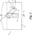
図1を見ると、本発明の第一実施形態による遠心分離装置が参照符号2で示してある。遠心分離装置は回転子シャフト4と回転子体3とを備え、前記回転子シャフトは遠心分離装置の中心に位置しており、この回転子シャフトを中心にして遠心分離装置2は回転可能である。さらに遠心分離装置2はサンプル容器8を保持するのに適合したサンプルホルダ6を備えている。サンプルホルダは、回転子シャフト4の軸線に対して垂直な軸線を有する一つ以上の保持ピン10により、遠心分離装置に取付けられている。保持ピンは回転子シャフト4を中心にして回転可能である。サンプルホルダ6は出し入れのための開口端部12を備え、この出し入れのための開口端部により、例えばピペットによるサンプルホルダ6の内部へのアクセスが可能である。Referring to FIG. 1, a centrifugal separator according to a first embodiment of the present invention is indicated by
使用する際、(図示していない)モーターは、回転子シャフト4を中心にして遠心分離装置2を回転させる。遠心力によって、サンプルホルダ6は参照符号14で示した位置から、参照符号16で示した位置まで旋回する。 In use, a motor (not shown) rotates the
静止位置14においてわかるように、サンプルホルダは回転子シャフトと一列に並んでいるが、これに反して旋回位置16において、サンプルホルダは回転子シャフト4に対して角度をなしている。 As can be seen at the
サンプルホルダ6の旋回範囲は、旋回ストップピン18により制限されている。旋回ストップピンの位置はサンプルの特性に応じて変えることがある。 The swivel range of the
ホルダ軸線は縦方向の回転子軸線からわずかにずれているか、あるいは回転開始時に、生じる遠心力によりサンプルホルダが良好に規定された方向にある角度で旋回するように、外側が重くなっている。これにより、少量の液体を扱う際に遠心分離中の回転子体の正確なバランスが得られるように、回転子体内における、適切な釣合おもりのバランスが計算できかつ説明することできる。明らかなように、サンプルホルダ6のアクセス端部12は、保持ピン10により正確に位置決めされている。回転の前後どちらにおいても、サンプルホルダは位置14で示した静止位置をとる。そこにおいて出し入れのための開口端部12も同じ位置を有する。これにより、出し入れのための開口端部12の位置決めが回転前後のどちらにおいても一定であるので、ピペット操作ロボットによるサンプルホルダへのアクセスが容易になる。The holder axis is slightly offset from the longitudinal rotor axis, or the outside is heavy so that at the start of rotation, thesample holder turns at a certain angle in a well defined direction due to the centrifugal force produced. Thus, as the exact balance of therotor body in the centrifuge when dealing with small amount of liquid is obtained, in therotor body, may be balanced appropriate counterweight it can and will be described calculations. As can be seen, the access end 12 of the
さらに、サンプルホルダ6の縦方向軸線が静止位置の回転子軸線とほぼ平行なので、ピペット操作ロボットは、サンプルホルダ6の出し入れのための開口端部12に対して支障なくアクセスできる。Furthermore, since the vertical axis of the
図2を見ると、本発明の第二実施形態が示してある。図1に関して記載された部品の類似の部品には、わかり易くする目的で、対応する参照符号を付与した。 Turning to FIG. 2, a second embodiment of the present invention is shown. Parts similar to those described with respect to FIG. 1 have been given corresponding reference numerals for the sake of clarity.
遠心分離装置2はさらに案内溝20を備え、この案内溝の内部で保持ピン10は可動である。使用時に、いったん遠心分離装置2の回転が始まると、サンプルホルダ6は静止位置14から図2には図示していない位置に移動し、この位置は静止位置14に対してほぼ平行であり、かつ静止位置14から間隔をおいて設けられている。この運動は案内溝20に沿った保持ピン10の運動を介して可能である。サンプルホルダ6は移動するので、遠心力の作用のために旋回し位置22をとる。大きな遠心力が必要なときに、この配設は好ましい。サンプルホルダ6の運動は旋回ストップピン18により制限される。The
図3を見ると、本発明の第三実施形態が示してある。さらに、わかり易くするために、図1及び2に示した実施形態に共通な部品には、対応する参照符号を付与した。遠心分離装置2はさらにバランスチューブ24を備え、このバランスチューブは円滑な運転を可能にするのに有利であり、かつサンプルの質量が回転子体の質量に対して大きく、遠心速度が高い場合に、回転子体の損傷を防ぐのにも有利である。バランスチューブは保持ピン10を中心にして自由に旋回し、かつサンプルホルダ6に対して反対方向に旋回するように配置されている。バランスチューブ24の運動は、バランスストップピン26により制限されており、このバランスストップピンは旋回ストップピン18に対して対応する角度で位置決めされている。バランスチューブは、サンプルホルダ6とほぼ同じ質量を有しており、かつサンプルホルダ、サンプルチューブ及びサンプルを組合わせたのと同じ質量を有するように水で満たすことができる。Turning to FIG. 3, a third embodiment of the present invention is shown. Furthermore, for the sake of clarity, parts common to the embodiments shown in FIGS. 1 and 2 are given corresponding reference numerals. The
サンプルホルダ6が、静止位置にあるときに、中央のピペットのアクセス可能な位置を確実に占めるように、バランスチューブ24は、バランス静止停止ピン28により、遠心分離装置の中心に向かうその運動が制限される。 To ensure that the
サンプルホルダのバランスは図1に示した実施形態により明らかであるが、図2に示した実施形態のバランスは、同様な方法で達せられる。 The balance of the sample holder is apparent from the embodiment shown in FIG. 1, but the balance of the embodiment shown in FIG. 2 can be achieved in a similar manner.
本発明による遠心分離装置は、液体処理ロボットと接続して使用される。このような状況において、液体検出機構は、さらにサンプル容器8内に収容された液体の高さを検出するために使用することもできる。液体の高さの検出は、容量測定法を使用して行われる。液体処理ロボットを使用した場合、液体はロボットにより制御されたピペットにより、サンプル容器8内に供給される。液体の高さの検出が、容量測定法を使用して行われる際、ピペットは測定電極を備えている。サンプル容器8内において液体の高さを正確に測定可能であるには、測定電極に近接した高品質の基準平面が確実にあることが必要である。 The centrifugal separator according to the present invention is used in connection with a liquid processing robot. In such a situation, the liquid detection mechanism can also be used to detect the height of the liquid contained in the sample container 8. The detection of the height of the liquid is performed using a volumetric method. When a liquid processing robot is used, the liquid is supplied into the sample container 8 by a pipette controlled by the robot. When the detection of the liquid height is performed using a volumetric method, the pipette is equipped with a measuring electrode. In order to be able to accurately measure the height of the liquid in the sample container 8, it is necessary to ensure that there is a high quality reference plane close to the measuring electrode.
図4を見ると、本発明の別の実施形態を示してある。図1〜3に示した部品に相当する部品には各々に応じて対応する参照符号を付与した。 Turning to FIG. 4, another embodiment of the present invention is shown. Corresponding reference numerals are assigned to components corresponding to the components shown in FIGS.
図4に示した実施形態において、(その一方だけを示した)二つの保持ピン10は、回転子体3から延びている。サンプルホルダ6は(一方だけを示した)二つの凹部38を備えている。保持ピン10はサンプルホルダ6に対して凹部38と係合可能である。 In the embodiment shown in FIG. 4, two holding pins 10 (only one of which is shown) extend from the rotor body 3. The
液体の高さを正確に測定可能であるには、例えば一つ以上の保持ピン10を介したロボット作業台を備えたアース信号に、サンプルホルダを接続するのが有利である。In order to be able to accurately measure the height of the liquid, it is advantageous to connect the sample holder to a ground signal provided with arobot worktable , for example via one or more holding pins 10.
本発明のさらに別の実施形態を図5及び6に関連して以下に記載してある。これらの実施形態は、保持ピン10を介した、例えばロボット作業台の形態で、アース信号にサンプルホルダ6を接続するためのアース手段を備えている。図1〜3に示した本発明の実施形態における部品に相当する遠心分離装置2の部品には、理解を容易にするために対応する参照符号を付与した。Yet another embodiment of the present invention is described below in connection with FIGS. These embodiments comprise a grounding means for connecting the
図5を見ると、本発明による遠心分離装置は、参照符号2で示してある。遠心分離装置はバネを負荷した棒体32を備え、このバネを負荷した棒体は遠心分離装置2に動力を供給するのに使用されるモーターの静的サイト(static site)20内に取付けられている。バネを負荷した棒体32は、遠心分離装置2の下方で、回転子シャフト4の一方の端部22と接触状態になるように回転子シャフト4の中心に向かって延びている。端部22はモーターの動作サイト(moving site)を備え、バネを負荷した棒体32はコール集電舟(coal collector shoe)34を介して端部22と接触する。回転子シャフト4は鉄でできているのが一般的である。しかしながら、回転子シャフト4とコール集電舟34の間で良好な接触を得るために、シャフトは真鍮でできているのが好ましい。例えば、シャフト4は一つ以上のネジを使用してシャフト4の端部に取付けられた真鍮の薄板から形成されていてもよい。 Referring to FIG. 5, the centrifuge according to the present invention is indicated by
図6を見ると、本発明の別の実施形態が示してある。この実施形態では、バネを負荷した棒体36は、回転子体3の下方に位置決めされるようにロボット作業台26上に直接取付けられている。したがって、バネを負荷した棒体36はモーターの静的サイトに接続している。この時バネを負荷した棒体36は回転子体3の下面側に沿って延びており、かつトロリーポールの形状をとる。コール集電舟34は、トロリーポールの端部に取付けられている。バネを負荷した棒体と回転子体3の間の良好な接触を得るために、コール集電舟は少なくとも一部が真鍮から形成されているのが好ましい。Turning to FIG. 6, another embodiment of the present invention is shown. In this embodiment, the
図5及び6の各々において図示した実施形態のどちらにおいても、サンプルホルダ6と、保持ピン10と、ロボット作業台26と、回転子体3とは、各々導電材料でできているか、あるいは部材間の電気的結合を達するために、それらの内部において、少なくともワイヤのような導電材料の通路を採用している。In each of the embodiments illustrated in each of FIGS. 5 and 6, the
本発明の図示した二つの実施形態により、良好な電気的結合が達せられ、この電気的結合は、良好な参照平面を示す静的ロボット作業台26と、遠心分離装置の可動部である回転子体24との間で形成されている。The two illustrated embodiments of the present invention provide good electrical coupling, which includes a
図5及び6に示した二つの実施形態の間の大きな違いは、図5に示した実施形態では、シャフト4によりコール集電舟34に付される速度が、図6に示した実施形態のコール集電舟34に付される速度よりもかなり小さいことである。これは、図5に示した実施形態では、コール集電舟34がシャフト4の中心にだけ接触しているのに対して、図6に示した実施形態では、コール集電舟34が回転子体3と接触しているからである。従って、図6に示した実施形態のコール集電舟34の寿命は、図5に示した実施形態で使用されたコール集電舟34の寿命に比べて短い。 The major difference between the two embodiments shown in FIGS. 5 and 6 is that in the embodiment shown in FIG. 5, the speed applied by the shaft 4 to the
図7を見ると、本発明による遠心分離装置の別の実施形態が示してある。 Turning to FIG. 7, another embodiment of a centrifuge according to the present invention is shown.
ある状況においては、遠心分離装置2の運転により振動が生じる。感度の良好な部材がロボット作業台26上に位置決めされている場合、振動を最小限にすることが重要である。回転子体3の形状は、遠心分離装置2の運転中に受ける振動のレベルに影響を及ぼすことがある。In certain situations, vibrations are generated by operation of the
さらに振動を最小にするには、わずかな負荷、すなわちサンプルホルダ6内に位置決めされたサンプル容器8内のわずかな流体を備えた回転子体3のバランス言い換えればカウンタウェイトと、サンプルホルダ6の旋回のわずかな角度とを計算しなければならない。振動は、遠心分離装置が全体としてバランスがとれた場合に最小になる。 In order to further minimize vibrations, the balance of the rotor body 3 with a slight load, i.e. a small amount of fluid in the sample container 8 positioned in the
さらに、ゴムのサスペンションは、遠心分離装置2内に搭載されている。図7に示した実施形態では、四つのゴムのサスペンションが配置されており、遠心分離機がロボット作業台と直接的および/または固い結合を全く有さないように、ゴムのサスペンションが一つ、モーターの各角隅部に位置決めされている。ゴムのサスペンションにより、
ロボット作業台26に伝達された残ったままの振動は、そのほとんどかあるいは全部が減衰する。Further, a rubber suspension is mounted in the
Most or all of the remaining vibration transmitted to therobot work table 26 is attenuated.
Claims (22)
Translated fromJapaneseホルダ軸線が回転子軸線に対して角度を形成していて、位置決め手段が、遠心分離装置内部において、サンプルホルダ(6)の出し入れのための開口端部(12)を正確に位置決めしている様式の遠心分離装置において、
位置決め手段が、回転子軸線に対してほぼ垂直である軸線を有する保持ピン(10)を備え、この保持ピンが回転子軸線を中心にして、遠心分離装置の回転子体(3)と共に回転可能であること、及び
サンプルホルダ(6)がホルダ半径を備えており、保持ピン(10)の軸線が、ホルダ半径よりも小さい間隔分だけ回転子軸線から間隔をおいて配置されていることを特徴とする遠心分離装置。For positioning the sample holder (6) in the centrifuge so that the rotor body (3), the sample holder (6) and the sample holder (6) are rotatable about the rotor axis. Positioning means, the rotor body (3) includes a rotor shaft (4) having a longitudinal rotation axis, and thesample holder (6) includes aninlet end (12) and a holder axis. A centrifuge device comprising:
A mode inwhich the holder axis forms an angle with respect to the rotor axis , and the positioning means accurately positionsthe open end (12) for taking in andout of thesample holder (6) inside the centrifugal separator. In the centrifuge of
The positioning means comprises a holding pin (10) having an axis that is substantially perpendicular to the rotor axis, and this holding pin is rotatablewith the rotor body (3) of thecentrifuge device about the rotor axis And
A centrifuge characterized in that thesample holder (6) has a holder radius, and the axis of theholding pin (10) is spaced from the rotor axis by a distance smaller than the holder radius. .
ピペットを容器に移動させる工程と、
材料を容器内に供給する工程とを備えていることを特徴とする請求項21の装置を使用して、サンプルホルダの内側に配置された容器内にサンプル材料を移送する方法。Filling the pipette with material; and
Moving the pipette into the container;
Feeding the material into the container, using the apparatus of claim 21 to transfer the sample material into the container located inside thesample holder .
Applications Claiming Priority (2)
| Application Number | Priority Date | Filing Date | Title |
|---|---|---|---|
| GBGB0303913.8AGB0303913D0 (en) | 2003-02-21 | 2003-02-21 | Robot centrifugation device |
| PCT/GB2004/000718WO2004073868A1 (en) | 2003-02-21 | 2004-02-23 | Centrifugation device with swingable sample holder |
Publications (3)
| Publication Number | Publication Date |
|---|---|
| JP2006518271A JP2006518271A (en) | 2006-08-10 |
| JP2006518271A5 JP2006518271A5 (en) | 2008-09-25 |
| JP4540613B2true JP4540613B2 (en) | 2010-09-08 |
Family
ID=9953372
Family Applications (1)
| Application Number | Title | Priority Date | Filing Date |
|---|---|---|---|
| JP2005518722AExpired - LifetimeJP4540613B2 (en) | 2003-02-21 | 2004-02-23 | Centrifuge with swivelable sample holder |
Country Status (10)
| Country | Link |
|---|---|
| US (1) | US7322926B2 (en) |
| EP (1) | EP1599290B1 (en) |
| JP (1) | JP4540613B2 (en) |
| CN (1) | CN100417452C (en) |
| AT (1) | ATE456401T1 (en) |
| CA (1) | CA2515974C (en) |
| DE (1) | DE602004025330D1 (en) |
| DK (1) | DK1599290T3 (en) |
| GB (1) | GB0303913D0 (en) |
| WO (1) | WO2004073868A1 (en) |
Families Citing this family (20)
| Publication number | Priority date | Publication date | Assignee | Title |
|---|---|---|---|---|
| GB0303913D0 (en)* | 2003-02-21 | 2003-03-26 | Sophion Bioscience As | Robot centrifugation device |
| US7422554B2 (en)* | 2005-08-10 | 2008-09-09 | The Drucker Company, Inc. | Centrifuge with aerodynamic rotor and bucket design |
| US8088593B2 (en) | 2007-10-02 | 2012-01-03 | Theranos, Inc. | Modular point-of-care devices, systems, and uses thereof |
| JP5945282B2 (en)* | 2011-01-21 | 2016-07-05 | セラノス, インコーポレイテッド | System and method for maximizing sample usage |
| US8475739B2 (en) | 2011-09-25 | 2013-07-02 | Theranos, Inc. | Systems and methods for fluid handling |
| JP6132597B2 (en)* | 2012-03-05 | 2017-05-24 | ローム株式会社 | Centrifugal force application device for microchip |
| US8911634B2 (en) | 2012-08-07 | 2014-12-16 | Molecular Devices, Llc | Apparatus and method for separating materials of different densities |
| US9199216B2 (en) | 2012-08-07 | 2015-12-01 | Molecular Devices, Llc | Apparatuses and methods for conditioning and reorienting components of an electrophysiology measurement system |
| CN106132555B (en)* | 2013-11-11 | 2019-07-26 | 生命科技股份有限公司 | Rotor assembly and method of use |
| CN104549781B (en)* | 2015-02-03 | 2017-01-11 | 南京天河汽车零部件股份有限公司 | Rotary liquid and chip removal centrifugal machine of hexahedral cavity of mechanical part |
| EP3216517B1 (en)* | 2016-03-10 | 2018-09-12 | Siemens Healthcare Diagnostics Products GmbH | Method for mixing a liquid in an automatic analyzer |
| EP3421134B1 (en)* | 2017-06-27 | 2020-09-30 | Tecan Trading Ag | Centrifugal processing unit |
| EP3421133B1 (en)* | 2017-06-27 | 2020-09-16 | Tecan Trading Ag | Centrifugal processing unit |
| CN107499581B (en)* | 2017-09-18 | 2023-07-28 | 哈尔滨圣泰生物制药有限公司 | Knockout support |
| CN108033116A (en)* | 2017-12-07 | 2018-05-15 | 金恩升 | A kind of food inspection sampling vasculum |
| EP3549664A1 (en) | 2018-04-05 | 2019-10-09 | F. Hoffmann-La Roche AG | Method and device for sonicating a biological sample |
| JP6992884B2 (en)* | 2018-05-11 | 2022-01-13 | 株式会社島津製作所 | Sample container holding mechanism |
| EP4135907A4 (en)* | 2020-04-14 | 2024-04-24 | Sandstone Diagnostics, Inc. | Devices and methods for portable and compact centrifugation |
| CN115870109B (en)* | 2022-12-07 | 2023-08-22 | 上海医涯医疗科技有限公司 | Horizontal centrifugal rotor, cell separation device and method |
| CN116689167B (en)* | 2023-07-12 | 2024-06-28 | 杭州佑宁仪器有限公司 | Miniature high-speed centrifuge |
Family Cites Families (28)
| Publication number | Priority date | Publication date | Assignee | Title |
|---|---|---|---|---|
| DE271653C (en) | ||||
| US2018837A (en)* | 1933-07-12 | 1935-10-29 | Collatz Ewald | Centrifugal device |
| US3202348A (en)* | 1962-12-05 | 1965-08-24 | Martin Christ | Centrifuge having an improved centrifuge cell |
| US3270563A (en)* | 1963-10-02 | 1966-09-06 | Pennsalt Chemicals Corp | Apparatus for analyzing for particle size distribution |
| US3666171A (en)* | 1969-10-20 | 1972-05-30 | Sorvall Inc Ivan | Swinging bucket centrifuge rotor |
| US3951334A (en) | 1975-07-07 | 1976-04-20 | E. I. Du Pont De Nemours And Company | Method and apparatus for automatically positioning centrifuge tubes |
| US4009824A (en)* | 1975-12-31 | 1977-03-01 | Beckman Instruments, Inc. | Swinging bucket centrifuge rotor |
| US4032066A (en)* | 1976-03-15 | 1977-06-28 | Beckman Instruments, Inc. | Adapters for centrifuge rotors |
| DE2822446C2 (en) | 1978-05-23 | 1983-08-25 | Heraeus-Christ Gmbh, 3360 Osterode | Centrifuge for the plasmapheresis process |
| US4360149A (en)* | 1980-11-10 | 1982-11-23 | Hein Jr George N | Centrifuge rotor with liquid supported swinging tubes |
| DE3116520A1 (en)* | 1981-04-25 | 1982-11-18 | Heraeus-Christ Gmbh, 3360 Osterode | "CENTRIFUGAL ROTOR" |
| JPS58154662A (en) | 1982-03-10 | 1983-09-14 | Hitachi Ltd | Automatic analyzer with pre-processing function |
| JPS5992355A (en) | 1982-11-19 | 1984-05-28 | Seiko Instr & Electronics Ltd | Chemical manipulator |
| DE3425922C2 (en)* | 1984-07-13 | 1986-05-28 | Kabushiki Kaisha Kubota Seisakusho, Tokio/Tokyo | Bucket for hanging on a swivel rotor of a centrifuge |
| JPS6234602Y2 (en)* | 1985-08-12 | 1987-09-03 | ||
| JPS631468A (en)* | 1986-06-20 | 1988-01-06 | Nittec Co Ltd | Rotor device of centrifugal separator |
| DD271653A1 (en)* | 1988-05-04 | 1989-09-13 | Medizin Labortechnik Veb K | SWIVEL CUP ROTOR FOR LABORATORY CENTRIFUGES |
| FR2665378B1 (en)* | 1990-08-03 | 1992-10-09 | Guigan Jean | DEVICE FOR SEPARATING BY CENTRIFUGATION TWO PHASES FROM A SAMPLE OF A HETEROGENEOUS LIQUID, USABLE IN PARTICULAR FOR THE SEPARATION OF TOTAL BLOOD PLASMA. |
| US5588946A (en)* | 1994-06-24 | 1996-12-31 | Johnson & Johnson Clinical Diagnostics, Inc. | Centrifuge and phase separation |
| JPH08141436A (en)* | 1994-11-25 | 1996-06-04 | Matsushita Electric Ind Co Ltd | Centrifuge |
| US6196961B1 (en) | 1998-03-19 | 2001-03-06 | Hitachi Koki Co., Ltd. | Automatic centrifugal machine employing a link arm mechanism |
| FR2785206B1 (en) | 1998-10-14 | 2001-01-19 | Fond Jean Dausset Ceph | CENTRIFUGATION DEVICE FOR LABORATORY AUTOMATON |
| DE10017904A1 (en) | 2000-04-11 | 2001-10-18 | Hettich Andreas Gmbh & Co Kg | Rapid automatic loader for swing-rotor centrifuge separating e.g. blood plasma for analysis includes system dispensing fluid into reservoir for perfect balancing |
| US6491615B1 (en) | 2000-08-11 | 2002-12-10 | Gentra Systems, Inc. | Rotor locator |
| US7150858B2 (en)* | 2000-08-18 | 2006-12-19 | Arkray, Inc. | Centrifugal separator |
| US20030091473A1 (en) | 2001-02-08 | 2003-05-15 | Downs Robert Charles | Automated centrifuge and method of using same |
| KR20040001439A (en)* | 2002-06-28 | 2004-01-07 | (주)바이오넥스 | Automated centrifuge system |
| GB0303913D0 (en)* | 2003-02-21 | 2003-03-26 | Sophion Bioscience As | Robot centrifugation device |
- 2003
- 2003-02-21GBGBGB0303913.8Apatent/GB0303913D0/ennot_activeCeased
- 2004
- 2004-02-23CNCNB2004800035467Apatent/CN100417452C/ennot_activeExpired - Lifetime
- 2004-02-23JPJP2005518722Apatent/JP4540613B2/ennot_activeExpired - Lifetime
- 2004-02-23USUS10/542,564patent/US7322926B2/ennot_activeExpired - Lifetime
- 2004-02-23EPEP04713586Apatent/EP1599290B1/ennot_activeExpired - Lifetime
- 2004-02-23CACA002515974Apatent/CA2515974C/ennot_activeExpired - Fee Related
- 2004-02-23WOPCT/GB2004/000718patent/WO2004073868A1/enactiveApplication Filing
- 2004-02-23DKDK04713586.8Tpatent/DK1599290T3/enactive
- 2004-02-23DEDE602004025330Tpatent/DE602004025330D1/ennot_activeExpired - Lifetime
- 2004-02-23ATAT04713586Tpatent/ATE456401T1/ennot_activeIP Right Cessation
Also Published As
| Publication number | Publication date |
|---|---|
| JP2006518271A (en) | 2006-08-10 |
| DE602004025330D1 (en) | 2010-03-18 |
| GB0303913D0 (en) | 2003-03-26 |
| CN1747787A (en) | 2006-03-15 |
| CA2515974A1 (en) | 2004-09-02 |
| CA2515974C (en) | 2008-12-30 |
| EP1599290B1 (en) | 2010-01-27 |
| US20060287182A1 (en) | 2006-12-21 |
| DK1599290T3 (en) | 2010-05-03 |
| EP1599290A1 (en) | 2005-11-30 |
| US7322926B2 (en) | 2008-01-29 |
| ATE456401T1 (en) | 2010-02-15 |
| WO2004073868A1 (en) | 2004-09-02 |
| CN100417452C (en) | 2008-09-10 |
Similar Documents
| Publication | Publication Date | Title |
|---|---|---|
| JP4540613B2 (en) | Centrifuge with swivelable sample holder | |
| US9211543B2 (en) | Holder for transferring test tube | |
| CN104640637B (en) | High-speed minicentrifuge for small sample volumes | |
| KR100606264B1 (en) | Automatic equilibrium centrifuge with fluid compensation | |
| US8469870B2 (en) | Swing rotor having improved holding pin for centrifugal separator and centrifugal separator including the same | |
| KR20040001439A (en) | Automated centrifuge system | |
| DK164721B (en) | TEST PROCESSING EQUIPMENT FOR A CENTRIFUGE | |
| US4141489A (en) | Swinging carrier centrifuge rotor | |
| EP3102334A1 (en) | High speed, compact centrifuge for use with small sample volumes | |
| US20210278425A1 (en) | Centering unit for diagnostic laboratory transporting compartment | |
| JP2000500573A (en) | Method and apparatus for sedimentation and optical inspection of particles suspended in a fluid and cuvette for achieving the method | |
| US4671940A (en) | Automatic centrifugal balancing mechanism | |
| JP2010064012A (en) | Centrifugal separator | |
| WO2005100933A1 (en) | Lift type weight measuring apparatus | |
| EP0195321B1 (en) | Automatic centrifugal balancing mechanism | |
| CN117871842A (en) | Fully automatic single molecule immunoassay analyzer | |
| CN116673135A (en) | Internally compensated cell and tissue centrifugation device with switchable counterweight | |
| JPH01189359A (en) | Centrifugal separator | |
| CN219291675U (en) | Self-positioning centrifugal machine driving mechanism | |
| JP2015049174A (en) | Centrifuge apparatus, centrifuge tube and method for automated cell preparation | |
| CN221951430U (en) | Blood centrifuge | |
| CN219150423U (en) | Balancing centrifuge tube for centrifuge, centrifuge tube kit and centrifuge | |
| CN213967180U (en) | Centrifugal cup placing rack of high-speed centrifuge | |
| LU103022B1 (en) | Sample purification device | |
| US20240175840A1 (en) | Electrode holder |
Legal Events
| Date | Code | Title | Description |
|---|---|---|---|
| A977 | Report on retrieval | Free format text:JAPANESE INTERMEDIATE CODE: A971007 Effective date:20071213 | |
| A131 | Notification of reasons for refusal | Free format text:JAPANESE INTERMEDIATE CODE: A131 Effective date:20080122 | |
| A601 | Written request for extension of time | Free format text:JAPANESE INTERMEDIATE CODE: A601 Effective date:20080421 | |
| A602 | Written permission of extension of time | Free format text:JAPANESE INTERMEDIATE CODE: A602 Effective date:20080428 | |
| RD13 | Notification of appointment of power of sub attorney | Free format text:JAPANESE INTERMEDIATE CODE: A7433 Effective date:20080514 | |
| A601 | Written request for extension of time | Free format text:JAPANESE INTERMEDIATE CODE: A601 Effective date:20080520 | |
| A602 | Written permission of extension of time | Free format text:JAPANESE INTERMEDIATE CODE: A602 Effective date:20080527 | |
| A521 | Request for written amendment filed | Free format text:JAPANESE INTERMEDIATE CODE: A821 Effective date:20080514 | |
| A601 | Written request for extension of time | Free format text:JAPANESE INTERMEDIATE CODE: A601 Effective date:20080620 | |
| A602 | Written permission of extension of time | Free format text:JAPANESE INTERMEDIATE CODE: A602 Effective date:20080627 | |
| A521 | Request for written amendment filed | Free format text:JAPANESE INTERMEDIATE CODE: A523 Effective date:20080722 | |
| A524 | Written submission of copy of amendment under article 19 pct | Free format text:JAPANESE INTERMEDIATE CODE: A524 Effective date:20080722 | |
| A131 | Notification of reasons for refusal | Free format text:JAPANESE INTERMEDIATE CODE: A131 Effective date:20090728 | |
| A521 | Request for written amendment filed | Free format text:JAPANESE INTERMEDIATE CODE: A523 Effective date:20090811 | |
| RD15 | Notification of revocation of power of sub attorney | Free format text:JAPANESE INTERMEDIATE CODE: A7435 Effective date:20090812 | |
| TRDD | Decision of grant or rejection written | ||
| RD04 | Notification of resignation of power of attorney | Free format text:JAPANESE INTERMEDIATE CODE: A7424 Effective date:20100526 | |
| A01 | Written decision to grant a patent or to grant a registration (utility model) | Free format text:JAPANESE INTERMEDIATE CODE: A01 Effective date:20100601 | |
| A01 | Written decision to grant a patent or to grant a registration (utility model) | Free format text:JAPANESE INTERMEDIATE CODE: A01 | |
| A61 | First payment of annual fees (during grant procedure) | Free format text:JAPANESE INTERMEDIATE CODE: A61 Effective date:20100622 | |
| R150 | Certificate of patent or registration of utility model | Ref document number:4540613 Country of ref document:JP Free format text:JAPANESE INTERMEDIATE CODE: R150 Free format text:JAPANESE INTERMEDIATE CODE: R150 | |
| FPAY | Renewal fee payment (event date is renewal date of database) | Free format text:PAYMENT UNTIL: 20130702 Year of fee payment:3 | |
| R250 | Receipt of annual fees | Free format text:JAPANESE INTERMEDIATE CODE: R250 | |
| R250 | Receipt of annual fees | Free format text:JAPANESE INTERMEDIATE CODE: R250 | |
| R250 | Receipt of annual fees | Free format text:JAPANESE INTERMEDIATE CODE: R250 | |
| R250 | Receipt of annual fees | Free format text:JAPANESE INTERMEDIATE CODE: R250 | |
| R250 | Receipt of annual fees | Free format text:JAPANESE INTERMEDIATE CODE: R250 | |
| R250 | Receipt of annual fees | Free format text:JAPANESE INTERMEDIATE CODE: R250 | |
| R250 | Receipt of annual fees | Free format text:JAPANESE INTERMEDIATE CODE: R250 | |
| R250 | Receipt of annual fees | Free format text:JAPANESE INTERMEDIATE CODE: R250 | |
| R250 | Receipt of annual fees | Free format text:JAPANESE INTERMEDIATE CODE: R250 | |
| R250 | Receipt of annual fees | Free format text:JAPANESE INTERMEDIATE CODE: R250 | |
| R250 | Receipt of annual fees | Free format text:JAPANESE INTERMEDIATE CODE: R250 | |
| EXPY | Cancellation because of completion of term |