JP4539492B2 - Backlight device, backlight driving method, and liquid crystal display device - Google Patents
Backlight device, backlight driving method, and liquid crystal display deviceDownload PDFInfo
- Publication number
- JP4539492B2 JP4539492B2JP2005232385AJP2005232385AJP4539492B2JP 4539492 B2JP4539492 B2JP 4539492B2JP 2005232385 AJP2005232385 AJP 2005232385AJP 2005232385 AJP2005232385 AJP 2005232385AJP 4539492 B2JP4539492 B2JP 4539492B2
- Authority
- JP
- Japan
- Prior art keywords
- light emitting
- light
- emitting diode
- amount
- color
- Prior art date
- Legal status (The legal status is an assumption and is not a legal conclusion. Google has not performed a legal analysis and makes no representation as to the accuracy of the status listed.)
- Expired - Fee Related
Links
Images


Classifications
- G—PHYSICS
- G02—OPTICS
- G02F—OPTICAL DEVICES OR ARRANGEMENTS FOR THE CONTROL OF LIGHT BY MODIFICATION OF THE OPTICAL PROPERTIES OF THE MEDIA OF THE ELEMENTS INVOLVED THEREIN; NON-LINEAR OPTICS; FREQUENCY-CHANGING OF LIGHT; OPTICAL LOGIC ELEMENTS; OPTICAL ANALOGUE/DIGITAL CONVERTERS
- G02F1/00—Devices or arrangements for the control of the intensity, colour, phase, polarisation or direction of light arriving from an independent light source, e.g. switching, gating or modulating; Non-linear optics
- G02F1/01—Devices or arrangements for the control of the intensity, colour, phase, polarisation or direction of light arriving from an independent light source, e.g. switching, gating or modulating; Non-linear optics for the control of the intensity, phase, polarisation or colour
- G02F1/13—Devices or arrangements for the control of the intensity, colour, phase, polarisation or direction of light arriving from an independent light source, e.g. switching, gating or modulating; Non-linear optics for the control of the intensity, phase, polarisation or colour based on liquid crystals, e.g. single liquid crystal display cells
- G02F1/133—Constructional arrangements; Operation of liquid crystal cells; Circuit arrangements
- G—PHYSICS
- G09—EDUCATION; CRYPTOGRAPHY; DISPLAY; ADVERTISING; SEALS
- G09G—ARRANGEMENTS OR CIRCUITS FOR CONTROL OF INDICATING DEVICES USING STATIC MEANS TO PRESENT VARIABLE INFORMATION
- G09G3/00—Control arrangements or circuits, of interest only in connection with visual indicators other than cathode-ray tubes
- G09G3/20—Control arrangements or circuits, of interest only in connection with visual indicators other than cathode-ray tubes for presentation of an assembly of a number of characters, e.g. a page, by composing the assembly by combination of individual elements arranged in a matrix no fixed position being assigned to or needed to be assigned to the individual characters or partial characters
- G09G3/34—Control arrangements or circuits, of interest only in connection with visual indicators other than cathode-ray tubes for presentation of an assembly of a number of characters, e.g. a page, by composing the assembly by combination of individual elements arranged in a matrix no fixed position being assigned to or needed to be assigned to the individual characters or partial characters by control of light from an independent source
- G09G3/3406—Control of illumination source
- G09G3/3413—Details of control of colour illumination sources
- G—PHYSICS
- G02—OPTICS
- G02F—OPTICAL DEVICES OR ARRANGEMENTS FOR THE CONTROL OF LIGHT BY MODIFICATION OF THE OPTICAL PROPERTIES OF THE MEDIA OF THE ELEMENTS INVOLVED THEREIN; NON-LINEAR OPTICS; FREQUENCY-CHANGING OF LIGHT; OPTICAL LOGIC ELEMENTS; OPTICAL ANALOGUE/DIGITAL CONVERTERS
- G02F1/00—Devices or arrangements for the control of the intensity, colour, phase, polarisation or direction of light arriving from an independent light source, e.g. switching, gating or modulating; Non-linear optics
- G02F1/01—Devices or arrangements for the control of the intensity, colour, phase, polarisation or direction of light arriving from an independent light source, e.g. switching, gating or modulating; Non-linear optics for the control of the intensity, phase, polarisation or colour
- G02F1/13—Devices or arrangements for the control of the intensity, colour, phase, polarisation or direction of light arriving from an independent light source, e.g. switching, gating or modulating; Non-linear optics for the control of the intensity, phase, polarisation or colour based on liquid crystals, e.g. single liquid crystal display cells
- G02F1/133—Constructional arrangements; Operation of liquid crystal cells; Circuit arrangements
- G02F1/1333—Constructional arrangements; Manufacturing methods
- G02F1/1335—Structural association of cells with optical devices, e.g. polarisers or reflectors
- G02F1/1336—Illuminating devices
- G02F1/133602—Direct backlight
- G02F1/133611—Direct backlight including means for improving the brightness uniformity
- G—PHYSICS
- G09—EDUCATION; CRYPTOGRAPHY; DISPLAY; ADVERTISING; SEALS
- G09G—ARRANGEMENTS OR CIRCUITS FOR CONTROL OF INDICATING DEVICES USING STATIC MEANS TO PRESENT VARIABLE INFORMATION
- G09G3/00—Control arrangements or circuits, of interest only in connection with visual indicators other than cathode-ray tubes
- G09G3/20—Control arrangements or circuits, of interest only in connection with visual indicators other than cathode-ray tubes for presentation of an assembly of a number of characters, e.g. a page, by composing the assembly by combination of individual elements arranged in a matrix no fixed position being assigned to or needed to be assigned to the individual characters or partial characters
- G09G3/34—Control arrangements or circuits, of interest only in connection with visual indicators other than cathode-ray tubes for presentation of an assembly of a number of characters, e.g. a page, by composing the assembly by combination of individual elements arranged in a matrix no fixed position being assigned to or needed to be assigned to the individual characters or partial characters by control of light from an independent source
- G09G3/3406—Control of illumination source
- G09G3/342—Control of illumination source using several illumination sources separately controlled corresponding to different display panel areas, e.g. along one dimension such as lines
- G—PHYSICS
- G09—EDUCATION; CRYPTOGRAPHY; DISPLAY; ADVERTISING; SEALS
- G09G—ARRANGEMENTS OR CIRCUITS FOR CONTROL OF INDICATING DEVICES USING STATIC MEANS TO PRESENT VARIABLE INFORMATION
- G09G2320/00—Control of display operating conditions
- G09G2320/04—Maintaining the quality of display appearance
- G09G2320/041—Temperature compensation
- G—PHYSICS
- G09—EDUCATION; CRYPTOGRAPHY; DISPLAY; ADVERTISING; SEALS
- G09G—ARRANGEMENTS OR CIRCUITS FOR CONTROL OF INDICATING DEVICES USING STATIC MEANS TO PRESENT VARIABLE INFORMATION
- G09G2320/00—Control of display operating conditions
- G09G2320/06—Adjustment of display parameters
- G09G2320/0626—Adjustment of display parameters for control of overall brightness
- G09G2320/0633—Adjustment of display parameters for control of overall brightness by amplitude modulation of the brightness of the illumination source
- G—PHYSICS
- G09—EDUCATION; CRYPTOGRAPHY; DISPLAY; ADVERTISING; SEALS
- G09G—ARRANGEMENTS OR CIRCUITS FOR CONTROL OF INDICATING DEVICES USING STATIC MEANS TO PRESENT VARIABLE INFORMATION
- G09G2320/00—Control of display operating conditions
- G09G2320/06—Adjustment of display parameters
- G09G2320/0626—Adjustment of display parameters for control of overall brightness
- G09G2320/064—Adjustment of display parameters for control of overall brightness by time modulation of the brightness of the illumination source
- G—PHYSICS
- G09—EDUCATION; CRYPTOGRAPHY; DISPLAY; ADVERTISING; SEALS
- G09G—ARRANGEMENTS OR CIRCUITS FOR CONTROL OF INDICATING DEVICES USING STATIC MEANS TO PRESENT VARIABLE INFORMATION
- G09G2320/00—Control of display operating conditions
- G09G2320/06—Adjustment of display parameters
- G09G2320/0666—Adjustment of display parameters for control of colour parameters, e.g. colour temperature
- G—PHYSICS
- G09—EDUCATION; CRYPTOGRAPHY; DISPLAY; ADVERTISING; SEALS
- G09G—ARRANGEMENTS OR CIRCUITS FOR CONTROL OF INDICATING DEVICES USING STATIC MEANS TO PRESENT VARIABLE INFORMATION
- G09G2330/00—Aspects of power supply; Aspects of display protection and defect management
- G09G2330/02—Details of power systems and of start or stop of display operation
- G09G2330/026—Arrangements or methods related to booting a display
- G—PHYSICS
- G09—EDUCATION; CRYPTOGRAPHY; DISPLAY; ADVERTISING; SEALS
- G09G—ARRANGEMENTS OR CIRCUITS FOR CONTROL OF INDICATING DEVICES USING STATIC MEANS TO PRESENT VARIABLE INFORMATION
- G09G2360/00—Aspects of the architecture of display systems
- G09G2360/14—Detecting light within display terminals, e.g. using a single or a plurality of photosensors
- G09G2360/145—Detecting light within display terminals, e.g. using a single or a plurality of photosensors the light originating from the display screen
Landscapes
- Physics & Mathematics (AREA)
- Engineering & Computer Science (AREA)
- General Physics & Mathematics (AREA)
- Nonlinear Science (AREA)
- Theoretical Computer Science (AREA)
- Computer Hardware Design (AREA)
- Crystallography & Structural Chemistry (AREA)
- Optics & Photonics (AREA)
- Chemical & Material Sciences (AREA)
- Mathematical Physics (AREA)
- Liquid Crystal (AREA)
- Circuit Arrangement For Electric Light Sources In General (AREA)
- Liquid Crystal Display Device Control (AREA)
- Control Of Indicators Other Than Cathode Ray Tubes (AREA)
- Led Devices (AREA)
Description
Translated fromJapanese本発明は、非発光の透過型の表示部の背面側に設けられるバックライト装置、バックライト駆動方法及び液晶表示装置に関するものである。 The present invention relates to a backlight device, a backlight driving method, and a liquid crystal display device provided on the back side of a non-light-emitting transmissive display unit.
液晶パネルのバックライトでは、蛍光管を使ったCCFL(Cold Cathode Fluorescent Lamp)タイプが主流であるが、環境的に水銀レスが要求されてきている。このことから、近年、CCFLに変わる光源としてLEDが有望視されている。特に、赤色LED、緑色LED、青色LEDの各原色を個別に使用し、光学的に合成加法混色して白色光を得る方法は、色のバランスがとりやすいため、テレビジョン用途として用いることが盛んに検討されている。 As the backlight of the liquid crystal panel, a CCFL (Cold Cathode Fluorescent Lamp) type using a fluorescent tube is the mainstream, but mercury-less is demanded environmentally. For this reason, in recent years, LEDs have been promising as light sources to replace CCFLs. In particular, the method of obtaining white light by individually using each primary color of red LED, green LED, and blue LED and optically combining and additive color mixing is easy to balance the colors, so it is widely used for television applications. Has been considered.
LEDをバックライトの光源として用いる場合、赤色LED、緑色LED、青色LEDの発光効率が異なるため、各色のLEDに流す電流も他の色と独立していなければならない。また、各々の色で使用するLEDは半導体組成が異なるために、色毎に素子の電圧にも相違があり、消費電力も異なる。また、LEDをバックライトの光源として用いる場合、現実的なコストの観点から、それぞれのLEDを個別に駆動するようなことはできない(例えば、特許文献1参照)。 When an LED is used as a light source for a backlight, the red LED, the green LED, and the blue LED have different luminous efficiencies. Therefore, the current that flows through each color LED must be independent of the other colors. Moreover, since the LED used for each color has a different semiconductor composition, the voltage of the element is different for each color, and the power consumption is also different. Moreover, when using LED as a light source of a backlight, from a viewpoint of realistic cost, it cannot drive each LED separately (for example, refer patent document 1).
このような赤色LED、緑色LED、青色LEDを光源として用いるバックライトでは、これら各色の光を一定の比率で光学的に合成して、常に所定の色度の白色光を生成しなければならない。そのため、赤、緑、青のフォトセンサにより各色の光量検出しながら、それぞれのグループのLEDに流す電流をフィードバック制御により調整することによって、赤、緑、青を一定の比率で合成して、所定の色度の白色光に調整している。 In a backlight using such red LEDs, green LEDs, and blue LEDs as light sources, the light of each color must be optically combined at a fixed ratio to always generate white light of a predetermined chromaticity. Therefore, red, green and blue photosensors detect the amount of light for each color and adjust the currents that flow through the LEDs in each group by feedback control to synthesize red, green and blue at a fixed ratio, It is adjusted to white light of chromaticity.
ところが、このようなフィードバック制御の応答が早いと色度が頻繁に変わり、ユーザに容易に視認されてしまう。このような色度が頻繁に変わる不都合を避けるため、フィードバック制御は、通常はゆっくりとした応答に設定される。したがって、電源投入時は、このようなフィードバック制御による色度の調整は期待できない。 However, if the response of such feedback control is fast, the chromaticity changes frequently and is easily recognized by the user. In order to avoid such inconvenience that the chromaticity changes frequently, the feedback control is usually set to a slow response. Therefore, when the power is turned on, adjustment of chromaticity by such feedback control cannot be expected.
そのため、このようなLEDを光源としたバックライトにおいては、赤、緑、青毎に予め初期の電流量(例えば、PWMのデューティ比)を算出しておき、電源投入直後は、この初期電流量により各色のLEDを駆動するようにしている。この初期電流量は、例えば、工場出荷前にそのバックライトの特性に応じて算出されるが、この値を最適に設定することができれば、電源投入をしてから所定の色度に収束するまでの時間をより短くすることができる。 For this reason, in a backlight using such an LED as a light source, an initial current amount (for example, PWM duty ratio) is calculated in advance for each of red, green, and blue, and the initial current amount immediately after power-on. Thus, each color LED is driven. This initial current amount is calculated according to the characteristics of the backlight before shipment from the factory, for example. If this value can be set optimally, the power will be turned on until it converges to a predetermined chromaticity. Can be shortened.
なお、初期電流量が最適に設定されておらず所定の色度に収束するまでの時間が長くなってしまう場合、画面上では、最初はピンク色の状態となっており、その徐々に白色に近づいていくといった現象が起こってしまう。 If the initial current amount is not optimally set and the time until it converges to the specified chromaticity is long, the screen is initially pink and gradually becomes white. The phenomenon of approaching will occur.
ところで、バックライトの光源としてLEDを用いた場合、大量のLEDを用いることとなるので、電源投入直後のLEDの温度と、定常動作時(温度が一定となった状態)におけるLED温度とは大きな差が生じる。また、LEDの光学特性は、温度に依存して大きく変動する。従って、電源投入直後のLEDの光学特性と、定常動作時のLEDの光学特性も大きく変動してしまう。 By the way, when LEDs are used as the light source of the backlight, a large amount of LEDs are used. Therefore, the LED temperature immediately after power-on and the LED temperature during steady operation (temperature is constant) are large. There is a difference. Further, the optical characteristics of the LED greatly vary depending on the temperature. Therefore, the optical characteristics of the LED immediately after the power is turned on and the optical characteristics of the LED during steady operation also vary greatly.
そのため、電源投入時に各LEDの供給する最適な初期電流量を予め算出しておいたとしても、その電源投入時の温度が変動してしまった場合には、その値が最適とはならず、電源投入をしてからある所定の色度となるまでの時間を短くすることができない。 Therefore, even if the optimal initial current supplied by each LED at the time of power-on is calculated in advance, if the temperature at the time of power-on fluctuates, the value is not optimal, The time from when the power is turned on until the predetermined chromaticity is reached cannot be shortened.
本発明は、このような従来の実状に鑑みて提案されたものであり、電源投入時の温度に関わらず、電源投入直後から所定の色度に収束するまでに要する時間が長くなってしまうのを防止することが可能なLEDを用いたバックライト装置、バックライト駆動方法及び液晶表示装置を提供することを目的とする。 The present invention has been proposed in view of such a conventional situation, and it takes a long time to converge to a predetermined chromaticity immediately after power-on, regardless of the temperature at the time of power-on. An object of the present invention is to provide a backlight device, a backlight driving method, and a liquid crystal display device using an LED capable of preventing the above.
本発明は、3色以上の複数の発光ダイオードを光源として有し、各色の発光ダイオードから発生された光を合成して白色光を生成し、生成した白色光を表示部の背面側から照射するバックライト装置において、上記発光ダイオードの温度を検出する温度センサと、上記発光ダイオードに電流を供給して駆動する駆動制御手段と、各色の発光ダイオードの初期電流量と、その初期電流量の温度に応じた補正量とが格納された記憶手段とを備え、上記駆動制御手段は、電源投入時に、上記温度センサの検出値に基づき補正量を算出し、算出した補正量を各色の発光ダイオードの初期電流量に加算し、補正した初期電流量で各色の発光ダイオードを起動することを特徴とする。 The present invention has a plurality of light emitting diodes of three or more colors as a light source, combines the light generated from the light emitting diodes of the respective colors to generate white light, and irradiates the generated white light from the back side of the display unit. In the backlight device, a temperature sensor that detects the temperature of the light emitting diode, a drive control unit that drives the light emitting diode by supplying current, an initial current amount of each color light emitting diode, and a temperature of the initial current amount. And a storage means for storing a correction amount according to the drive control means, when the power is turned on, the drive control means calculates a correction amount based on the detection value of the temperature sensor, and the calculated correction amount is the initial value of the light emitting diode of each color. The light emitting diodes of the respective colors are activated with the corrected initial current amount by adding to the current amount.
また、本発明は、3色以上の複数の発光ダイオードを光源として有し、各色の発光ダイオードから発生された光を合成して白色光を生成し、生成した白色光を表示部の背面側から照射するバックライト装置を駆動するバックライト駆動方法であって、各色の発光ダイオードの初期電流量と、その初期電流量の温度に応じた補正量とを記憶しておき、電源投入時に、上記発光ダイオードの温度を検出する温度センサの検出値に基づき補正量を算出し、算出した補正量を各色の発光ダイオードの初期電流量に加算し、補正した初期電流量で各色の発光ダイオードを起動し、上記白色光が所定の色度となるように、上記白色光の色度を検出する色度センサの検出値に基づき各色の発光ダイオードの電流量をフィードバック制御することを特徴とする。 Further, the present invention has a plurality of light emitting diodes of three or more colors as light sources, generates white light by combining light generated from the light emitting diodes of the respective colors, and generates the generated white light from the back side of the display unit. A backlight driving method for driving a backlight device to irradiate, storing an initial current amount of each color light emitting diode and a correction amount corresponding to the temperature of the initial current amount, and when the power is turned on, the light emission Calculate the correction amount based on the detection value of the temperature sensor that detects the temperature of the diode, add the calculated correction amount to the initial current amount of the light emitting diode of each color, start the light emitting diode of each color with the corrected initial current amount, The amount of current of the light emitting diode of each color is feedback controlled based on a detection value of a chromaticity sensor that detects the chromaticity of the white light so that the white light has a predetermined chromaticity.
また、本発明は、3色以上の複数の発光ダイオードを光源として有し、各色の発光ダイオードから発生された光を合成して白色光を生成するバックライト装置と、上記バックライト装置により生成した白色光が背面側から照射される透過型のカラー液晶表示パネルからなる液晶表示装置であって、上記バックライト装置は、上記発光ダイオードの温度を検出する温度センサと、上記白色光の色度を検出する色度センサと、上記発光ダイオードに電流を供給して駆動する駆動制御手段と、各色の発光ダイオードの初期電流量と、その初期電流量の温度に応じた補正量とが格納された記憶手段とを備え、上記駆動制御手段は、電源投入時に、上記温度センサの検出値に基づき補正量を算出し、算出した補正量を各色の発光ダイオードの初期電流量に加算し、補正した初期電流量で各色の発光ダイオードを起動し、その後に上記白色光が所定の色度となるように、上記色度センサの検出値に基づき各色の発光ダイオードの電流量をフィードバック制御することを特徴とする。 The present invention also includes a backlight device that has a plurality of light emitting diodes of three or more colors as light sources, generates white light by combining light generated from the light emitting diodes of the respective colors, and the backlight device. A liquid crystal display device comprising a transmissive color liquid crystal display panel irradiated with white light from the back side, wherein the backlight device comprises a temperature sensor for detecting the temperature of the light emitting diode, and the chromaticity of the white light. A chromaticity sensor to be detected, drive control means for supplying and driving current to the light emitting diode, a memory storing an initial current amount of each color light emitting diode and a correction amount corresponding to the temperature of the initial current amount The drive control means calculates a correction amount based on the detection value of the temperature sensor when the power is turned on, and the calculated correction amount is used as the initial current amount of the light emitting diode of each color. Add up and start each color light emitting diode with the corrected initial current amount, and then feed back the current amount of each color light emitting diode based on the detected value of the chromaticity sensor so that the white light has a predetermined chromaticity It is characterized by controlling.
本発明によれば、電源投入時の温度に関わらず、電源投入直後から所定の色度に収束するまでに要する時間を短くすることができる。 According to the present invention, the time required to converge to a predetermined chromaticity immediately after power-on can be shortened regardless of the temperature at the time of power-on.
以下、本発明の実施の形態について、図面を参照して詳細に説明する。 Hereinafter, embodiments of the present invention will be described in detail with reference to the drawings.
本発明は、例えば図1に示すような構成のバックライト方式の液晶表示部1を備えるカラー液晶表示装置に適用される。 The present invention is applied to, for example, a color liquid crystal display device including a backlight type liquid
(液晶表示部の構成)
液晶表示部1は、透過型のカラー液晶表示パネル10と、このカラー液晶表示パネル10の背面側に設けられたバックライト装置20とから構成されている。(Configuration of liquid crystal display)
The liquid
(パネル)
透過型のカラー液晶表示パネル10は、TFT基板11と対向電極基板12とを互いに対向配置させ、その間隙に例えばツイステッドネマチック(TN)液晶を封入した液晶層13を設けた構成となっている。TFT基板11にはマトリクス状に配置された信号線14と走査線15及びこれらの交点に配置されたスイッチング素子としての薄膜トランジスタ16と画素電極17が形成されている。薄膜トランジスタ16は走査線15により順次選択されると共に、信号線14から供給される映像信号を対応する画素電極17に書き込む。一方、対向電極基板12の内表面には対向電極18及びカラーフィルタ19が形成されている。(panel)
The transmissive color liquid
液晶表示部1では、この様な構成の透過型のカラー液晶表示パネル10を2枚の偏光板で挟み、バックライト装置20により背面側から白色光を照射した状態で、アクティブマトリクス方式で駆動することによって、所望のフルカラー 映像表示が得られる。 The liquid
(バックライト)
バックライト装置20は、光源21と波長選択フィルタ22とを備えている。バックライト装置20は、光源21から発光された光を、波長選択フィルタ22を介してカラー液晶表示パネル10を背面側から照明する。このようなバックライト装置20は、透過型のカラー液晶表示パネル10を背面に配設され、カラー液晶表示パネル10の背面直下から照明する直下型タイプである。(Backlight)
The
ここで、バックライト装置20の光源21には、多数の発光ダイオード(LED:Light Emitting Diode)3が設けられ、この発光ダイオードから出射された光を出力する。光源21には、赤色の光を発光する多数の発光ダイオード3Rと、緑色の光を発光する多数の発光ダイオード3Gと、青色の光を発光する多数の発光ダイオード3Bが設けられている。光源21では、赤、青、緑の光を混合して白色光を生成し、この白色光をカラー液晶表示パネル10に出射している。 Here, the
バックライト装置20の光源21における発光ダイオード3の配置は、例えば、次のようになる。 For example, the arrangement of the
まず、図2に示すように、赤の発光ダイオード3R、緑の発光ダイオード3G及び青の発光ダイオード3Bをそれぞれ2個使用し、合計6個の発光ダイオードを一列に配列したもので単位セル(2G 2R 2B)を構成する。続いて、この単位セル(2G 2R 2B)をさらに3つずつ横方向に並べた中単位(6G 6R 6B)を構成する。そして、この中単位(6G 6R 6B)を、図3に示すように水平方向に直列接続し、直列接続したもの画面全体をカバーするように縦方向に並べる。 First, as shown in FIG. 2, two red light-emitting
このように発光ダイオードを配置することにより、赤色、緑色、青色の3色の発光ダイオードが混色され、バランスのよい白色光を発光する。なお、バランスよく混色されれば、図2,図3に示した配置に限らず、どのような配置であってもよい。 By arranging the light emitting diodes in this manner, the light emitting diodes of three colors of red, green, and blue are mixed and emit white light with a good balance. As long as the colors are mixed in a balanced manner, the arrangement is not limited to the arrangement shown in FIGS.
(カラー液晶表示装置の全体構成)
次に、カラー液晶表示装置30の全体構成例を図4に示す。(Overall configuration of color liquid crystal display device)
Next, an example of the overall configuration of the color liquid
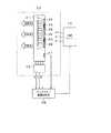
このカラー液晶表示装置30は、カラー液晶表示パネル10やバックライト装置20の駆動電源を供給する電源部31と、カラー液晶表示パネル10を駆動するXドライバ回路32及びYドライバ回路33と、外部から映像信号が入力端子34を介して供給されるRGBプロセス処理部35と、このRGBプロセス処理部35に接続された映像メモリ36及び制御部37と、バックライト装置20の駆動制御するバックライト駆動制御部38とを備えている。 The color liquid
入力端子34を介して入力された映像信号は、RGBプロセス処理部35によりクロマ処理等の信号処理がなされ、さらに、コンポジット信号からカラー液晶表示パネル10の駆動に適したRGBセパレート信号に変換されて、制御部37に供給されるとともに、映像メモリ36を介してXドライバ回路32に供給される。また、制御部37は、上記RGBセパレート信号に応じた所定のタイミングでXドライバ回路32及びYドライバ回路33を制御して、上記映像メモリ36を介してXドライバ回路32に供給されるRGBセパレート信号でカラー液晶表示パネル10を駆動することにより、上記RGBセパレート信号に応じた映像を表示する。 The video signal input via the input terminal 34 is subjected to signal processing such as chroma processing by the RGB
また、カラー液晶表示装置30には、図4及び図5に示すように、バックライト装置20の光源21(発光ダイオード)の温度を検出する温度センサ41と、バックライト装置20の光源21(発光ダイオード)のR,G,Bの各色の光量もしくは色度を検出する光量又は色度センサ42(42R,42G,42B)と、バックライト装置20の温度を冷却する冷却ファン43とを備えている。 4 and 5, the color liquid
温度センサ41の検出値及び光量又は色度センサ42の検出値は、バックライト駆動制御部38に供給される。バックライト駆動制御部38は、これらのセンサの検出値に基づき、光源21を構成する発光ダイオードの駆動電流の制御を行う。 The detection value of the
また、バックライト駆動制御部38は、温度センサ41の検出値に応じて冷却ファン43の回転速度の制御を行い、バックライト20の光源21(発光ダイオード)の温度の制御を行う。 Further, the backlight
また、バックライト駆動制御部38は、内部に不揮発性メモリ38aを有しており、当該不揮発性メモリ38aに各種の設定値が格納されている。 The backlight
(LED駆動回路)
また、バックライト駆動制御部38内には、バックライト装置20の光源21(発光ダイオード)を駆動するLED駆動回路50が複数個設けられている。(LED drive circuit)
Further, a plurality of
バックライト装置20の光源となる発光ダイオード3は、図6に示すように、水平方向に並んだ同一色毎の発光ダイオード3が、電気的に直列接続されている。LED駆動回路50は、水平方向に直列接続した発光ダイオード群3の一つ一つに独立して設けられている。 As shown in FIG. 6, the light-emitting
図7は、バックライト駆動制御部38内に設けられたLED駆動回路50の回路構成例である。 FIG. 7 is a circuit configuration example of the
LED駆動回路50は、DC-DCコンバータ51と、定抵抗(Rc)52と、FET53と、PWM制御回路54と、コンデンサ55と、サンプルホールド用FET56と、抵抗57と、ホールドタイミング回路58、基準電源59とを備えている。 The
DC-DCコンバータ51は、図4に示した電源31から発生された直流電圧VINが入力され、入力された直流電力をスイッチングして安定化した直流の出力電圧Vccを発生する。DC-DCコンバータ51は、フィードバック端子Vfから入力された電圧と出力電圧Vccとの電位差が基準電圧値(Vref)となるように安定化した出力電圧Vccを発生する。なお、基準電圧値(Vref)は、基準電源59から供給される。 The DC-DC converter 51 receives the DC voltage VIN generated from the
直列接続した発光ダイオード群3のアノード側は、定抵抗(Rc)を介してDC-DCコンバータ51の出力電圧Vccの出力端と接続されている。また、直列接続した発光ダイオード群3のアノード側は、サンプルホールド用FET56のソース-ドレインを介してDC-DCコンバータ51のフィードバック端に接続されている。また、直列接続した発光ダイオード群3のカソード側は、FET53のソース-ドレイン間を介してグランドに接続されている。 The anode side of the light emitting
FET53のゲートには、PWM制御回路54から発生されたPWM信号が入力される。FET53は、PWM信号がオンのときにソース-ドレイン間がオンとなり、PWM信号がオフのときにソース-ドレイン間がオフとなる。従って、FET53は、PWM信号がオンのときに発光ダイオード群3に電流を流し、PWM信号がオフのときには発光ダイオード群3に流れる電流を0とする。すなわち、FET53は、PWM信号がオンのときに発光ダイオード群3を発光させ、PWM信号がオフのときには発光ダイオード群3の発光を停止させる。 The PWM signal generated from the PWM control circuit 54 is input to the gate of the FET 53. The FET 53 is turned on between the source and the drain when the PWM signal is turned on, and turned off between the source and the drain when the PWM signal is turned off. Therefore, the FET 53 causes a current to flow through the light emitting
PWM制御回路54は、オン時間及びオフ時間のデューティ比が調整される2値信号であるPWM信号を発生する。PWM制御回路54は、デューティの制御値(PWM)が供給され、この制御値(PWM)に応じてデューティ比を変更する。 The PWM control circuit 54 generates a PWM signal that is a binary signal in which the duty ratio of the on time and the off time is adjusted. The PWM control circuit 54 is supplied with a duty control value (PWM), and changes the duty ratio according to the control value (PWM).
コンデンサ55は、DC-DCコンバータ51の出力端とフィードバック端との間に設けられている。抵抗57は、DC-DCコンバータ51の出力端とサンプルホールド用FET56のゲートに接続されている。 The
ホールドタイミング回路58は、PWM信号が入力され、PWM信号の立ち上がりエッジで所定時間だけOFFとなり、その他の時間ではONとなるホールド信号を発生する。 The
サンプルホールド用FET56のゲートには、ホールドタイミング回路58から出力されたホールド信号が入力される。サンプルホールド用FET56は、ホールド信号がオフのときにソースードレイン間がオンとなり、ホールド信号がオンのときのソース-ドレイン間がオフとなる。 The hold signal output from the
以上のようなLED駆動回路50では、PWM制御回路54から発生されたPWM信号がオンとなる時間のみ発光ダイオード群3に電流ILEDが流される。また、コンデンサ55、サンプルホールド用FET56及び抵抗57によりサンプルホールド回路を構成している。このサンプルホールド回路は、発光ダイオード群3のアノード(すなわち、出力電圧Vccが接続されていない方の定抵抗52の一端)の電圧値を、PWM信号のオン時にサンプルし、DC-DCコンバータ51のフィードバック端に供給している。DC-DCコンバータ51は、フォードバック端に入力される電圧値に基づき、出力電圧Vccを安定化させるので、定抵抗Rc52及び発光ダイオード群3に流れる電流ILEDの波高値が一定となる。 In the
従って、LED駆動回路50では、発光ダイオード群3に流れる電流ILEDの波高値が一定とされた状態で、PWM信号に応じたパルス駆動される。 Therefore, the
なお、発光ダイオード群3に流れる電流量の調整は、本回路では、制御値(PWM)を変化させることにより行われる。しかしながら、DC-DCコンバータ51に与える基準電圧値(Vref)を変化させることにより発光ダイオード群3に流れる電流の波高値を調整してもよいし、又は、これらの組み合わせによって調整してもよい。 The amount of current flowing through the light emitting
(色度一定化のための制御方法)
つぎに、バックライト装置20から発光される白色光の色度を、ある特定の色度に収束して安定化させるための制御方法について説明をする。(Control method for constant chromaticity)
Next, a control method for converging and stabilizing the chromaticity of white light emitted from the
バックライト駆動制御部38は、バックライト装置20に電源が投入され、当該バックライト装置20から白色光が発光されると、赤色LED3R、緑色LED3G、青色LED3Bの光量比がある特定の比率となるように制御することによって、当該バックライト装置20から発光される白色光の特定の色度に安定化させている。 When the
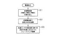
具体的には、図8に示すフローに従い、制御を行っている。 Specifically, control is performed according to the flow shown in FIG.
まず、ステップS1において、バックライト装置20の電源が投入されると、バックライト駆動制御部38は、不揮発性メモリ38a内に格納されている初期電流値(PWMR0,PWMG0,PWMB0)を読み出し、当該初期電流値により赤色LED3R、緑色LED3G、青色LED3Bを起動する。 First, in step S1, when the power of the
不揮発性メモリ38aには、初期電流値として、赤色LED3Rを駆動するための初期電流値PWMR0、緑色LED3Gを駆動するための初期電流値PWMG0、青色LED3Bを駆動するための初期電流値PWMB0が、それぞれ別の値として格納がされている。なお、本例では、発光ダイオード3は、PWM駆動がされる。そのため、初期電流値として格納されるのは、PWM制御のデューティ比となっている。もっとも、電流の波高値で電流量が制御される回路であれば、初期電流値として波高値が格納されることとなる。 In the nonvolatile memory 38a, initial current values PWMR0 for driving the
続いて、ステップS2において、バックライト駆動制御部38は、各色のLED3を、読み出した初期電流値(PWMR0,PWMG0,PWMB0)で駆動を開始する。LED3の駆動が開始されると、バックライト装置20から光が発光される。 Subsequently, in step S2, the backlight
続いて、ステップS3において、バックライト駆動制御部38は、バックライト装置20から発光される白色光(赤、緑、青の合成光)が所定の色度となるように、光量又は色度センサ42の検出出力に基づき、赤色LED3R、緑色LED3G及び青色LED3Bの各色の駆動電流(PWMデューティ比)をフィードバック制御する。 Subsequently, in step S3, the backlight
すなわち、光量又は色度センサ42により検出された赤色の光量をPhtR、緑色の光量をPhtG、青色の光量をPhtBとしたとき、PhtR:PhtG:PhtBが一定となるように制御を行う。 That is, control is performed so that PhtR: PhtG: PhtB is constant when the red light amount detected by the light amount or
(青色を基準に制御を行う理由)
ところで、色度を一定とするためのフィードバック制御を行う場合、3種類の電流量(赤、緑、青のLEDに流す電流量)を同時に調整しなければならないため、処理が非常に複雑となる。このため、バックライト駆動制御部38では、青色LED3Bに流す電流値を常時固定し、他の色(すなわち、赤と緑)のLED3R,3Gに流す電流を変更することで、一定の色度となるように調整が行われている。(Reason for control based on blue)
By the way, when feedback control is performed to keep the chromaticity constant, three types of current amounts (current amounts flowing through the red, green, and blue LEDs) must be adjusted at the same time, so the processing becomes very complicated. . For this reason, the backlight
このように青色(B)に流す電流を固定とすることで、フィードバック制御の各種演算に用いるパラメータを、青色(B)については全て“1”とし、赤色(R)及び緑色(G)については、青色(B)との比率で表したものとすることができる。 By fixing the current flowing in blue (B) in this way, the parameters used for various feedback control calculations are all set to “1” for blue (B), and for red (R) and green (G). , And can be expressed as a ratio to blue (B).
このため、取り扱う変数を2つにすることができ、演算処理が非常に簡単にとなる。 For this reason, two variables can be handled, and the arithmetic processing becomes very simple.
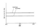
青色LED3Bの電流量を固定して制御を行うのは、次の理由による。 The reason why the control is performed with the current amount of the
もし、LEDの光学特性が温度に関係なく一定であれば、図9に示すように、光量又は色度センサ42の検出出力の青色を基準としたときの比(PhtR/PhtB,PhtG/PhtB)は、温度に関係なく一定となる。 If the optical characteristics of the LED are constant regardless of the temperature, as shown in FIG. 9, the ratio when the light quantity or the detection output of the
しかしながら、実際には、LEDの光学特性の温度変化は大きい。 However, in practice, the temperature change of the optical characteristics of the LED is large.
例えば、図10は、赤(R)、緑(G)、青(B)の各LED素子の発光波長に対する明るさを示したグラフである。図10には、温度が0℃、25℃、50℃のそれぞれの場合についてのグラフを示している。なお、図10のグラフは、x軸方向に発光波長を示し、y軸方向に発光出力(明るさ)を示している。 For example, FIG. 10 is a graph showing the brightness with respect to the emission wavelength of each LED element of red (R), green (G), and blue (B). In FIG. 10, the graph about each case where temperature is 0 degreeC, 25 degreeC, and 50 degreeC is shown. The graph of FIG. 10 shows the emission wavelength in the x-axis direction and the emission output (brightness) in the y-axis direction.
この図10を参照してわかるように、各LED素子は、温度に対する発光量(曲線で囲まれた部分の面積)が変化するだけではなく、高温になるほど長波長側にシフトしている。特に、赤(R)のLED素子は、山形の頂点(ピーク)に相当する波長(ピーク波長)が、高温になるにしたがって大きく長波長側へのシフトしている。 As can be seen with reference to FIG. 10, each LED element not only changes the light emission amount with respect to temperature (the area of the portion surrounded by the curve), but also shifts to the longer wavelength side as the temperature increases. In particular, in the red (R) LED element, the wavelength (peak wavelength) corresponding to the peak (peak) of the chevron is greatly shifted to the longer wavelength side as the temperature increases.
従って、一定の色度となるようにフィードバック制御を行う際に、温度特性も考慮に入れた制御を行わなければ、精度の高い制御を行うことができない。 Therefore, when feedback control is performed so that the chromaticity is constant, control with high accuracy cannot be performed unless control that takes temperature characteristics into consideration is performed.
そのため、バックライト駆動制御部38では、光量又は色度センサ42の検出出力に基づき制御を行うと同時に、温度センサ41の検出出力に応じてその補正も行っている。このように温度も考慮して制御を行うことによって、図11に示すように、安定した色度とすることができる。 Therefore, the backlight
このように温度補正も同時に行っている場合、最も温度変化の小さい色を基準に処理を行うと、安定したフィードバック制御を行うことができる。逆に言えば、温度変化の大きい色を基準とした場合、基準値がずれるので安定したフィードバック制御を行うことが非常に困難となる。 In this way, when temperature correction is also performed at the same time, stable feedback control can be performed by performing processing based on the color with the smallest temperature change. In other words, when a color having a large temperature change is used as a reference, the reference value is shifted, so that it is very difficult to perform stable feedback control.
図10のグラフを見ると、青色の波長シフト及びピーク値の温度変化が一番小さい。 Looking at the graph of FIG. 10, the blue wavelength shift and the peak temperature change are the smallest.
そこで、バックライト駆動制御部38では、青色LED3Bの電流量を固定して制御を行っている。 Therefore, the backlight
(バックライトのオン時の温度オフセット)
また、バックライト駆動制御部38は、電源が投入時における初期電流値(PWMR0,PWMG0,PWMB0)を、温度センサ41により検出した温度に応じて、補正を行っている。(Temperature offset when the backlight is on)
The backlight
色度を一定とするためのフィードバック制御を行った場合、各色のLEDに流れる電流量(PWMのデューティ)の温度特性は、図12に示すようになる。 When feedback control is performed to keep the chromaticity constant, the temperature characteristics of the amount of current (PWM duty) flowing through the LEDs of the respective colors are as shown in FIG.
初期電流値(PWMR0,PWMG0,PWMB0)が例えば65℃の時の最適値に基づき定められているとすれば、図13に示すように、30℃の時には、初期値から赤色であれば約−20%の差分値(Rerr)、緑色であれば約−10%の差分(Gerr)が発生することとなる。なお、青色は、駆動電流(PWMデューティ)を一定にするように制御しているため、この差分は発生しない。そのため、例えば、バックライト装置20に電源を投入したときの温度が30℃であれば、これらの差分(Rerr,Gerr)だけフィードバック制御により収束させなければならない。 If the initial current values (PWMR0, PWMG0, PWMB0) are determined based on the optimum values at 65 ° C., for example, as shown in FIG. If the difference value (Rerr) is 20%, and the color is green, a difference (Gerr) of about −10% is generated. The blue color is controlled so that the drive current (PWM duty) is constant, so this difference does not occur. Therefore, for example, if the temperature when the
しかしながら、これら差分は比較的大きいので、収束までの時間が長くなる。収束時間が長くなると、画質上では、差分の大きいRの影響を受け、ピンクから徐々に白(本来の色度の白)に変化するのが視覚上わかってしまう。 However, since these differences are relatively large, the time until convergence becomes long. When the convergence time becomes long, it is visually recognized that the image quality is gradually changed from pink to white (original chromaticity white) under the influence of R having a large difference in image quality.
このような問題を解決するために、バックライト駆動制御部38では、バックライト装置20に電源を投入した温度(温度センサ41の値)を考慮し、不揮発性メモリ38aから読み出された初期値(PWMR0,PWMG0)を、例えば下記数1の式のように補正して、その補正値を駆動電流として各LEDに供給する。 In order to solve such a problem, the backlight

なお、数1の各パラメータは次の通りである。
PWMRt:赤色LEDに設定する電流量(補正した後の電流値)
PWMGt:緑色LEDに設定する電流量(補正した後の電流値)
T0:初期電流値(PWMR0,PWMG0,PWMB0)を算出したときの温度(例えば65℃)
T1:任意の温度
T:温度センサ41により検出した現在のバックライト装置20の温度
RerrT1:温度T1の時の赤色の差分(すなわち、PWMR0から、温度T1で所定の色度に収束した時の赤色LEDの電流量を減算した値)
GerrT1:温度T1の時の緑色の差分(すなわち、PWMG0から、温度T1で所定の色度に収束した時の緑色LEDの電流量を減算した値)。The parameters in
PWMRt: Amount of current set for the red LED (current value after correction)
PWMGt: Amount of current set for the green LED (current value after correction)
T0: temperature when the initial current value (PWMR0, PWMG0, PWMB0) is calculated (for example, 65 ° C.)
T1: Any temperature
T: Temperature RerrT1 of the
GerrT1: Green difference at temperature T1 (that is, a value obtained by subtracting the current amount of the green LED when converged to a predetermined chromaticity at temperature T1 from PWMG0).
以上のように、初期電流量を補正することにより、初期に与える電流量をより収束値に近づけることができ、収束までの時間(所定の色度の白色光に安定するまでの時間)を短くすることができる。 As described above, by correcting the initial current amount, the initial amount of current can be made closer to the convergence value, and the time until convergence (the time until stabilization to white light of a predetermined chromaticity) is shortened. can do.
なお、このRerrT1、GerrT1は、バックライト装置20の工場出荷前に予め算出して、不揮発性メモリ38aに格納しておく。この際、バックライト装置20一つ一つに対してRerrT1、GerrT1を算出してもよいし、例えば、生産製を考え、理論的に算出された値を格納するようにしてもよい。 The RerrT1 and GerrT1 are calculated in advance before the
10 カラー液晶パネル、20 バックライト装置、21 光源、30 カラー液晶表示装置、38 バックライト駆動制御部、41 温度センサ、42 光量又は色度センサ、43 冷却ファン DESCRIPTION OF
Claims (8)
Translated fromJapanese上記発光ダイオードの温度を検出する温度センサと、
上記発光ダイオードに電流を供給して駆動する駆動制御手段と、
各色の発光ダイオードの初期電流量と、その初期電流量の温度に応じた補正量とが格納された記憶手段とを備え、
上記駆動制御手段は、電源投入時に、上記温度センサの検出値に基づき補正量を算出し、算出した補正量を各色の発光ダイオードの初期電流量に加算し、補正した初期電流量で各色の発光ダイオードを起動する
ことを特徴とするバックライト装置。In a backlight device that has a plurality of light emitting diodes of three or more colors as light sources, generates white light by combining light generated from light emitting diodes of each color, and irradiates the generated white light from the back side of the display unit ,
A temperature sensor for detecting the temperature of the light emitting diode;
Drive control means for driving the light emitting diode by supplying current;
Storage means for storing an initial current amount of each color light emitting diode and a correction amount according to the temperature of the initial current amount;
When the power is turned on, the drive control unit calculates a correction amount based on the detection value of the temperature sensor, adds the calculated correction amount to the initial current amount of the light emitting diode of each color, and emits light of each color with the corrected initial current amount. A backlight device characterized by starting a diode.
上記駆動制御手段は、上記白色光が所定の色度となるように、上記色度センサの検出値に基づき各色の発光ダイオードの電流量をフィードバック制御することを特徴とする請求項1記載のバックライト装置。A chromaticity sensor for detecting the chromaticity of the white light,
2. The back according to claim 1, wherein the drive control means feedback-controls the amount of current of each color light emitting diode based on a detection value of the chromaticity sensor so that the white light has a predetermined chromaticity. Light equipment.
上記駆動制御手段は、青色の発光ダイオードに流す電流量を固定とし、赤色及び緑色に流す電流量を調整することにより、上記白色光が所定の色度となるようにフィードバック制御を行う
ことを特徴とする請求項2記載のバックライト装置。It has red, green and blue light emitting diodes as the light source,
The drive control unit performs feedback control so that the white light has a predetermined chromaticity by fixing the amount of current flowing through the blue light emitting diode and adjusting the amount of current flowing through red and green. The backlight device according to claim 2.
各色の発光ダイオードの初期電流量と、その初期電流量の温度に応じた補正量とを記憶しておき、電源投入時に、上記発光ダイオードの温度を検出する温度センサの検出値に基づき補正量を算出し、算出した補正量を各色の発光ダイオードの初期電流量に加算し、補正した初期電流量で各色の発光ダイオードを起動し、
上記白色光が所定の色度となるように、上記白色光の色度を検出する色度センサの検出値に基づき各色の発光ダイオードの電流量をフィードバック制御する
ことを特徴とするバックライト駆動方法。A backlight device having a plurality of light emitting diodes of three or more colors as a light source, generating white light by combining the light generated from the light emitting diodes of the respective colors, and irradiating the generated white light from the back side of the display unit A backlight driving method for driving,
The initial current amount of each color light emitting diode and the correction amount corresponding to the temperature of the initial current amount are stored, and the correction amount is determined based on the detection value of the temperature sensor that detects the temperature of the light emitting diode when the power is turned on. Calculate, add the calculated correction amount to the initial current amount of the light emitting diode of each color, start the light emitting diode of each color with the corrected initial current amount,
A backlight driving method characterized by feedback-controlling the amount of current of each color light-emitting diode based on a detection value of a chromaticity sensor that detects the chromaticity of the white light so that the white light has a predetermined chromaticity .
上記バックライト装置は、上記発光ダイオードの温度を検出する温度センサと、上記白色光の色度を検出する色度センサと、上記発光ダイオードに電流を供給して駆動する駆動制御手段と、各色の発光ダイオードの初期電流量と、その初期電流量の温度に応じた補正量とが格納された記憶手段とを備え、上記駆動制御手段は、電源投入時に、上記温度センサの検出値に基づき補正量を算出し、算出した補正量を各色の発光ダイオードの初期電流量に加算し、補正した初期電流量で各色の発光ダイオードを起動し、上記白色光が所定の色度となるように、上記色度センサの検出値に基づき各色の発光ダイオードの電流量をフィードバック制御する
ことを特徴とする液晶表示装置。A backlight device having a plurality of light emitting diodes of three or more colors as a light source and generating white light by combining light generated from the light emitting diodes of the respective colors, and white light generated by the backlight device from the back side A liquid crystal display device comprising an illuminated transmissive color liquid crystal display panel,
The backlight device includes a temperature sensor that detects a temperature of the light emitting diode, a chromaticity sensor that detects a chromaticity of the white light, a drive control unit that drives the light emitting diode by supplying a current, A storage unit storing an initial current amount of the light emitting diode and a correction amount corresponding to the temperature of the initial current amount; and the drive control unit corrects the correction amount based on a detection value of the temperature sensor when the power is turned on. And the calculated correction amount is added to the initial current amount of the light emitting diode of each color, the light emitting diode of each color is started with the corrected initial current amount, and the above-mentioned color is set so that the white light has a predetermined chromaticity. A liquid crystal display device, wherein the current amount of each color light emitting diode is feedback-controlled based on the detection value of the degree sensor.
上記駆動制御手段は、青色の発光ダイオードに流す電流量を固定とし、赤色及び緑色に流す電流量を調整することにより、上記白色光が所定の色度となるようにフィードバック制御を行うことを特徴とする請求項7記載の液晶表示装置。It has red, green and blue light emitting diodes as the light source,
The drive control unit performs feedback control so that the white light has a predetermined chromaticity by fixing the amount of current flowing through the blue light emitting diode and adjusting the amount of current flowing through red and green. The liquid crystal display device according to claim 7.
Priority Applications (6)
| Application Number | Priority Date | Filing Date | Title |
|---|---|---|---|
| JP2005232385AJP4539492B2 (en) | 2004-11-19 | 2005-08-10 | Backlight device, backlight driving method, and liquid crystal display device |
| KR1020050106905AKR101156391B1 (en) | 2004-11-19 | 2005-11-09 | Backlight device, method of driving backlight device and liquid crystal display apparatus |
| CN2008101312024ACN101339743B (en) | 2004-11-19 | 2005-11-17 | Backlight device, method of driving backlight device and liquid crystal display apparatus |
| US11/283,148US7982706B2 (en) | 2004-11-19 | 2005-11-18 | Backlight device, method of driving backlight and liquid crystal display apparatus |
| TW094140662ATWI335472B (en) | 2004-11-19 | 2005-11-18 | Backlight device, method of driving backlight and liquid crystal display apparatus |
| EP05257116AEP1675097A3 (en) | 2004-11-19 | 2005-11-18 | Backlight device, method of driving backlight and liquid crystal display apparatus |
Applications Claiming Priority (2)
| Application Number | Priority Date | Filing Date | Title |
|---|---|---|---|
| JP2004336572 | 2004-11-19 | ||
| JP2005232385AJP4539492B2 (en) | 2004-11-19 | 2005-08-10 | Backlight device, backlight driving method, and liquid crystal display device |
Related Child Applications (1)
| Application Number | Title | Priority Date | Filing Date |
|---|---|---|---|
| JP2010111154ADivisionJP2010237683A (en) | 2004-11-19 | 2010-05-13 | Backlight apparatus, method of driving backlight and liquid crystal display apparatus |
Publications (2)
| Publication Number | Publication Date |
|---|---|
| JP2006171693A JP2006171693A (en) | 2006-06-29 |
| JP4539492B2true JP4539492B2 (en) | 2010-09-08 |
Family
ID=36384348
Family Applications (1)
| Application Number | Title | Priority Date | Filing Date |
|---|---|---|---|
| JP2005232385AExpired - Fee RelatedJP4539492B2 (en) | 2004-11-19 | 2005-08-10 | Backlight device, backlight driving method, and liquid crystal display device |
Country Status (5)
| Country | Link |
|---|---|
| US (1) | US7982706B2 (en) |
| EP (1) | EP1675097A3 (en) |
| JP (1) | JP4539492B2 (en) |
| KR (1) | KR101156391B1 (en) |
| TW (1) | TWI335472B (en) |
Families Citing this family (121)
| Publication number | Priority date | Publication date | Assignee | Title |
|---|---|---|---|---|
| JP4904783B2 (en)* | 2005-03-24 | 2012-03-28 | ソニー株式会社 | Display device and display method |
| JP4371097B2 (en)* | 2005-09-20 | 2009-11-25 | エプソンイメージングデバイス株式会社 | LIGHTING DEVICE, ELECTRO-OPTICAL DEVICE, AND ELECTRONIC DEVICE |
| KR20070058087A (en)* | 2005-12-01 | 2007-06-07 | 삼성전자주식회사 | Backlight unit, its driving method and liquid crystal display device comprising the same |
| KR101228923B1 (en)* | 2006-03-02 | 2013-02-01 | 엘지이노텍 주식회사 | Apparatus for Uniformalizing Luminance of LCD |
| JP4869744B2 (en)* | 2006-03-09 | 2012-02-08 | 株式会社 日立ディスプレイズ | LED lighting device and liquid crystal display device using the same |
| US8067970B2 (en)* | 2006-03-31 | 2011-11-29 | Masleid Robert P | Multi-write memory circuit with a data input and a clock input |
| JP4922046B2 (en)* | 2006-04-07 | 2012-04-25 | サムソン エルイーディー カンパニーリミテッド. | Backlight unit using LED |
| TWI353571B (en)* | 2006-05-19 | 2011-12-01 | Mstar Semiconductor Inc | Lcd backlight signal generator |
| JP4175426B2 (en)* | 2006-05-30 | 2008-11-05 | ソニー株式会社 | Backlight device and color image display device |
| US20070291198A1 (en)* | 2006-06-16 | 2007-12-20 | Vastview Technology Inc. | Method and device for driving LED-based backlight module |
| KR20080001050A (en)* | 2006-06-29 | 2008-01-03 | 삼성전기주식회사 | LC backlight drive system with LED |
| KR100799869B1 (en)* | 2006-06-29 | 2008-01-31 | 삼성전기주식회사 | LC backlight drive system with LED |
| US7605550B2 (en)* | 2006-07-17 | 2009-10-20 | Microsemi Corp.—Analog Mixed Signal Group Ltd. | Controlled bleeder for power supply |
| JP4151717B2 (en) | 2006-07-21 | 2008-09-17 | ソニー株式会社 | Light source module, light source device, and liquid crystal display device |
| DE102006036829A1 (en)* | 2006-08-07 | 2008-02-14 | Wincor Nixdorf International Gmbh | Flat-panel display fault state detection device e.g. for cash dispenser, uses analysis device for comparing detected current with preset desired value |
| KR100858379B1 (en)* | 2006-08-31 | 2008-09-11 | 엘지이노텍 주식회사 | Backlight unit driving device and multi-sensing feedback control method |
| KR101251543B1 (en)* | 2006-09-01 | 2013-04-08 | 삼성디스플레이 주식회사 | Liquid crystal display apparatus and Method of driving the same and Method of fabricating the same |
| WO2008029548A1 (en)* | 2006-09-06 | 2008-03-13 | Sharp Kabushiki Kaisha | Illuminating device, backlight device, liquid crystal display device, method for controlling illuminating device and method for controlling liquid crystal display device |
| JP2008102490A (en)* | 2006-09-19 | 2008-05-01 | Funai Electric Co Ltd | Liquid crystal display device and liquid crystal television |
| FR2906396A1 (en)* | 2006-09-26 | 2008-03-28 | Thomson Licensing Sas | ELECTROLUMINESCENT DIODE ELEMENT ASSEMBLY FOR BACKLIGHT DEVICE, BACKLIGHT DEVICE, AND BACKLIGHT SCREEN. |
| JP2008097864A (en)* | 2006-10-06 | 2008-04-24 | Harison Toshiba Lighting Corp | Backlight device and driving method of backlight device |
| KR101182245B1 (en)* | 2006-10-16 | 2012-09-14 | 삼성전자주식회사 | Display apparatus and control method thereof |
| KR101183457B1 (en) | 2006-10-16 | 2012-09-14 | 삼성전자주식회사 | Liquid Crystal Display And Control Method Thereof |
| KR100968451B1 (en)* | 2006-10-16 | 2010-07-07 | 삼성전자주식회사 | Display device and control method |
| KR101123709B1 (en) | 2006-10-25 | 2012-03-15 | 삼성전자주식회사 | Display apparatus and control method thereof |
| JP4633035B2 (en)* | 2006-11-07 | 2011-02-16 | Necディスプレイソリューションズ株式会社 | Liquid crystal display device and liquid crystal display device control method |
| WO2008056321A1 (en)* | 2006-11-10 | 2008-05-15 | Koninklijke Philips Electronics N.V. | Method and driver for determining drive values for driving a lighting device |
| JP4264558B2 (en) | 2006-11-10 | 2009-05-20 | ソニー株式会社 | Backlight device, backlight driving method, and color image display device |
| KR101370339B1 (en) | 2006-12-04 | 2014-03-05 | 삼성전자 주식회사 | Back Light Apparatus And Control Method Thereof |
| JP5177999B2 (en) | 2006-12-05 | 2013-04-10 | 株式会社半導体エネルギー研究所 | Liquid crystal display |
| KR100859030B1 (en)* | 2006-12-06 | 2008-09-17 | 엘지이노텍 주식회사 | LED backlight unit |
| US8233013B2 (en)* | 2006-12-21 | 2012-07-31 | Sharp Kabushiki Kaisha | Transmissive-type liquid crystal display device |
| KR20080058859A (en)* | 2006-12-22 | 2008-06-26 | 삼성전자주식회사 | Display device and its color temperature adjustment method |
| JP4889520B2 (en)* | 2007-02-22 | 2012-03-07 | シャープ株式会社 | Video display device |
| KR101410465B1 (en)* | 2007-02-22 | 2014-06-23 | 삼성디스플레이 주식회사 | Backlight device and liquid crystal display device having the same |
| KR101306138B1 (en)* | 2007-02-28 | 2013-09-17 | 엘지디스플레이 주식회사 | LCD including Temperature compensation circuit and driving method of the same |
| JP5079360B2 (en)* | 2007-03-15 | 2012-11-21 | ローム株式会社 | Light emitting diode drive device |
| US20080238856A1 (en)* | 2007-03-29 | 2008-10-02 | Achintva Bhowmik | Using spatial distribution of pixel values when determining adjustments to be made to image luminance and backlight |
| JP5510859B2 (en)* | 2007-03-30 | 2014-06-04 | Nltテクノロジー株式会社 | Backlight device and liquid crystal display device |
| JP2008268642A (en)* | 2007-04-23 | 2008-11-06 | Sony Corp | Backlight device, method for controlling backlight and liquid crystal display device |
| US8049709B2 (en) | 2007-05-08 | 2011-11-01 | Cree, Inc. | Systems and methods for controlling a solid state lighting panel |
| JP4720782B2 (en)* | 2007-05-09 | 2011-07-13 | ソニー株式会社 | Image display device |
| US7579786B2 (en) | 2007-06-04 | 2009-08-25 | Applied Concepts, Inc. | Method, apparatus, and system for driving LED's |
| US11488545B2 (en) | 2007-06-13 | 2022-11-01 | Interdigital Madison Patent Holdings, Sas | Device for displaying images comprising two modulation stages |
| EP2020655A1 (en)* | 2007-07-25 | 2009-02-04 | Funai Electric Co., Ltd. | Liquid crystal display device and liquid crystal television |
| US20090033612A1 (en)* | 2007-07-31 | 2009-02-05 | Roberts John K | Correction of temperature induced color drift in solid state lighting displays |
| US8264448B2 (en) | 2007-09-21 | 2012-09-11 | Point Somee Limited Liability Company | Regulation of wavelength shift and perceived color of solid state lighting with temperature variation |
| US8253666B2 (en)* | 2007-09-21 | 2012-08-28 | Point Somee Limited Liability Company | Regulation of wavelength shift and perceived color of solid state lighting with intensity and temperature variation |
| US8368636B2 (en) | 2007-09-21 | 2013-02-05 | Point Somee Limited Liability Company | Regulation of wavelength shift and perceived color of solid state lighting with intensity variation |
| JP5007650B2 (en)* | 2007-10-16 | 2012-08-22 | ソニー株式会社 | Display device, light amount adjustment method for display device, and electronic device |
| US8031166B2 (en)* | 2007-11-06 | 2011-10-04 | Hisense Beijing Electric Co., Ltd. | Liquid crystal display method and the appratus thereof |
| KR101494003B1 (en)* | 2007-11-30 | 2015-02-16 | 엘지전자 주식회사 | Apparatus and method for back light control, and terminal with the same |
| JP2009163945A (en)* | 2007-12-28 | 2009-07-23 | Sony Corp | Light source system and display |
| JP5348906B2 (en)* | 2008-02-26 | 2013-11-20 | パナソニック株式会社 | lighting equipment |
| JP5642347B2 (en)* | 2008-03-07 | 2014-12-17 | ミツミ電機株式会社 | LCD backlight device |
| US8125163B2 (en) | 2008-05-21 | 2012-02-28 | Manufacturing Resources International, Inc. | Backlight adjustment system |
| JP2011529204A (en)* | 2008-07-23 | 2011-12-01 | クォルコム・メムズ・テクノロジーズ・インコーポレーテッド | Pixel element calibration |
| JPWO2010016440A1 (en)* | 2008-08-08 | 2012-01-19 | シャープ株式会社 | Backlight and display device using the same |
| JP2010112967A (en)* | 2008-08-29 | 2010-05-20 | Toshiba Corp | Video reproducing apparatus and method for controlling illumination device |
| US20100253613A1 (en)* | 2008-10-02 | 2010-10-07 | Manufacturing Resources International, Inc. | Led backlight and electronic control |
| CN101719345B (en)* | 2008-10-09 | 2012-12-05 | 立锜科技股份有限公司 | LED display system, control method thereof, driver and control method of the system |
| JP5446217B2 (en)* | 2008-11-07 | 2014-03-19 | ソニー株式会社 | Display devices and electronic devices |
| KR101573434B1 (en)* | 2008-12-02 | 2015-12-02 | 삼성디스플레이 주식회사 | A light source driving method, a light source device for performing the same, and a display device having the light source device |
| TWI406229B (en)* | 2008-12-16 | 2013-08-21 | Chunghwa Picture Tubes Ltd | Light source display displayed by color sequent |
| US8358085B2 (en) | 2009-01-13 | 2013-01-22 | Terralux, Inc. | Method and device for remote sensing and control of LED lights |
| US9326346B2 (en) | 2009-01-13 | 2016-04-26 | Terralux, Inc. | Method and device for remote sensing and control of LED lights |
| JP4496270B1 (en) | 2009-01-30 | 2010-07-07 | 株式会社東芝 | Video display device and video display method |
| CA2754371C (en)* | 2009-02-24 | 2017-11-21 | Manufacturing Resources International, Inc. | System and method for controlling the operation parameters of a display in response to current draw |
| US8700226B2 (en)* | 2009-02-24 | 2014-04-15 | Manufacturing Resources International, Inc. | Method for driving a cooling fan within an electronic display |
| US8575865B2 (en)* | 2009-03-24 | 2013-11-05 | Apple Inc. | Temperature based white point control in backlights |
| EP2438588A4 (en) | 2009-06-03 | 2013-01-16 | Mri Inc | Dynamic dimming led backlight |
| US20110109233A1 (en)* | 2009-11-12 | 2011-05-12 | Silicon Touch Technology Inc. | Multi-channel current driver |
| CA2781077A1 (en)* | 2009-11-17 | 2012-06-28 | Terralux, Inc. | Led power-supply detection and control |
| TWI427598B (en)* | 2009-12-29 | 2014-02-21 | Au Optronics Corp | Backlight module and method of determining driving currents thereof |
| JP5307763B2 (en)* | 2010-05-28 | 2013-10-02 | 三菱電機照明株式会社 | LED lighting device and lighting fixture |
| US9596738B2 (en) | 2010-09-16 | 2017-03-14 | Terralux, Inc. | Communication with lighting units over a power bus |
| CA2810026A1 (en) | 2010-09-16 | 2012-03-22 | Terralux, Inc. | Communication with lighting units over a power bus |
| US20130271511A1 (en)* | 2010-11-30 | 2013-10-17 | Ryuuichi Fujimura | Display device and color-correction method for display device |
| US8773451B2 (en)* | 2011-05-03 | 2014-07-08 | Apple Inc. | Color correction method and apparatus for displays |
| JP5615226B2 (en) | 2011-05-11 | 2014-10-29 | キヤノン株式会社 | LIGHT CONTROL DEVICE, ITS CONTROL METHOD, AND DISPLAY DEVICE |
| KR101894081B1 (en)* | 2011-09-06 | 2018-09-04 | 엘지이노텍 주식회사 | Method for controlling luminous intensity of a light emitting device and lighting device using the same |
| EP2769376A4 (en) | 2011-09-23 | 2015-07-22 | Mri Inc | SYSTEM AND METHOD FOR ENVIRONMENTALLY ADAPTING DISPLAY CHARACTERISTICS |
| US8687026B2 (en)* | 2011-09-28 | 2014-04-01 | Apple Inc. | Systems and method for display temperature detection |
| US9361822B2 (en)* | 2011-11-09 | 2016-06-07 | Apple Inc. | Color adjustment techniques for displays |
| WO2013090904A1 (en) | 2011-12-16 | 2013-06-20 | Terralux, Inc. | System and methods of applying bleed circuits in led lamps |
| WO2013099165A1 (en)* | 2011-12-26 | 2013-07-04 | シャープ株式会社 | Liquid crystal display device |
| US20150145972A1 (en)* | 2012-06-05 | 2015-05-28 | Sharp Kabushiki Kaisha | Liquid crystal display device and method for controlling same |
| US9348174B2 (en) | 2013-03-14 | 2016-05-24 | Manufacturing Resources International, Inc. | Rigid LCD assembly |
| US9265119B2 (en) | 2013-06-17 | 2016-02-16 | Terralux, Inc. | Systems and methods for providing thermal fold-back to LED lights |
| JP5355816B2 (en)* | 2013-06-27 | 2013-11-27 | 三菱電機株式会社 | LED lighting device and lighting fixture |
| US9690137B2 (en) | 2013-07-03 | 2017-06-27 | Manufacturing Resources International, Inc. | Airguide backlight assembly |
| CN103606352A (en)* | 2013-11-15 | 2014-02-26 | 深圳市华星光电技术有限公司 | A backlight drive circuit, a driving method thereof, a backlight module and a liquid crystal display |
| US10191212B2 (en) | 2013-12-02 | 2019-01-29 | Manufacturing Resources International, Inc. | Expandable light guide for backlight |
| CN106030833B (en)* | 2014-04-08 | 2018-08-28 | 夏普株式会社 | LED drive circuit |
| US10527276B2 (en) | 2014-04-17 | 2020-01-07 | Manufacturing Resources International, Inc. | Rod as a lens element for light emitting diodes |
| CN104036707A (en)* | 2014-05-26 | 2014-09-10 | 京东方科技集团股份有限公司 | Display device detection device and method and display system |
| US10649273B2 (en) | 2014-10-08 | 2020-05-12 | Manufacturing Resources International, Inc. | LED assembly for transparent liquid crystal display and static graphic |
| US10593255B2 (en) | 2015-05-14 | 2020-03-17 | Manufacturing Resources International, Inc. | Electronic display with environmental adaptation of display characteristics based on location |
| US9924583B2 (en) | 2015-05-14 | 2018-03-20 | Mnaufacturing Resources International, Inc. | Display brightness control based on location data |
| US10607520B2 (en) | 2015-05-14 | 2020-03-31 | Manufacturing Resources International, Inc. | Method for environmental adaptation of display characteristics based on location |
| US20160374165A1 (en)* | 2015-06-18 | 2016-12-22 | Innolux Corporation | Backlight module and liquid-crystal display device using the same |
| US10261362B2 (en) | 2015-09-01 | 2019-04-16 | Manufacturing Resources International, Inc. | Optical sheet tensioner |
| DE102016104440B4 (en)* | 2016-03-10 | 2025-10-02 | Inova Semiconductors Gmbh | Method and device for brightness compensation of an LED |
| US10032418B2 (en)* | 2016-05-09 | 2018-07-24 | Japan Display Inc. | Display apparatus |
| WO2018009917A1 (en) | 2016-07-08 | 2018-01-11 | Manufacturing Resources International, Inc. | Controlling display brightness based on image capture device data |
| US10175417B2 (en)* | 2016-10-31 | 2019-01-08 | Facebook Technologies, Llc | Thick backlight for RGB LED of a liquid crystal display used in a virtual reality head mounted display |
| CN114695425A (en)* | 2016-12-22 | 2022-07-01 | 夏普株式会社 | Display device and manufacturing method |
| EP4250721A3 (en) | 2017-02-15 | 2024-02-07 | Lazurite Holdings LLC | Wireless medical imaging system comprising a head unit and a light cable that comprises an integrated light source |
| US11877101B2 (en)* | 2017-12-04 | 2024-01-16 | Sony Corporation | Image display apparatus |
| CN110462548A (en)* | 2018-03-29 | 2019-11-15 | 深圳市大疆创新科技有限公司 | Control method, display equipment, remote controler and the unmanned plane suit of fan |
| US10578658B2 (en) | 2018-05-07 | 2020-03-03 | Manufacturing Resources International, Inc. | System and method for measuring power consumption of an electronic display assembly |
| WO2019241546A1 (en) | 2018-06-14 | 2019-12-19 | Manufacturing Resources International, Inc. | System and method for detecting gas recirculation or airway occlusion |
| WO2020209295A1 (en)* | 2019-04-11 | 2020-10-15 | 株式会社小糸製作所 | Vehicle lamp and lighting circuit for same |
| JP7351518B2 (en)* | 2019-12-04 | 2023-09-27 | 株式会社松村電機製作所 | LED drive circuit, LED lighting system, and LED drive method |
| US11526044B2 (en) | 2020-03-27 | 2022-12-13 | Manufacturing Resources International, Inc. | Display unit with orientation based operation |
| CN111462702B (en)* | 2020-04-21 | 2022-08-02 | 海信视像科技股份有限公司 | Display device backlight control method and display device |
| AU2022238796B2 (en) | 2021-03-15 | 2024-09-19 | Manufacturing Resources International, Inc. | Fan control for electronic display assemblies |
| US12105370B2 (en) | 2021-03-15 | 2024-10-01 | Manufacturing Resources International, Inc. | Fan control for electronic display assemblies |
| CN115968081A (en)* | 2021-10-12 | 2023-04-14 | 致伸科技股份有限公司 | Input device with backlight function and method for adjusting backlight color |
| US12027132B1 (en) | 2023-06-27 | 2024-07-02 | Manufacturing Resources International, Inc. | Display units with automated power governing |
| US12429726B1 (en) | 2023-10-02 | 2025-09-30 | Manufacturing Resources International, Inc. | Optical stack with a liquid crystal layer and a micro lens array, electronic display assembly, and related methods |
Family Cites Families (24)
| Publication number | Priority date | Publication date | Assignee | Title |
|---|---|---|---|---|
| JPH07226536A (en)* | 1994-02-14 | 1995-08-22 | Stanley Electric Co Ltd | LED color information display board |
| JP4050802B2 (en)* | 1996-08-02 | 2008-02-20 | シチズン電子株式会社 | Color display device |
| JP2000315596A (en)* | 1999-04-28 | 2000-11-14 | Toshiba Lighting & Technology Corp | Lighting device and display device |
| JP3445540B2 (en)* | 1999-11-16 | 2003-09-08 | 常盤電業株式会社 | Power circuit |
| JP3939066B2 (en)* | 2000-03-08 | 2007-06-27 | 富士通日立プラズマディスプレイ株式会社 | Color plasma display device |
| JP2001257921A (en)* | 2000-03-14 | 2001-09-21 | Ricoh Co Ltd | Digital camera |
| JP2001272938A (en) | 2000-03-28 | 2001-10-05 | Sharp Corp | Color tone adjustment circuit, backlight module including the circuit, and light emitting diode display device |
| US6621482B2 (en) | 2000-05-15 | 2003-09-16 | Koninklijke Philips Electronics N.V. | Display arrangement with backlight means |
| US6441558B1 (en)* | 2000-12-07 | 2002-08-27 | Koninklijke Philips Electronics N.V. | White LED luminary light control system |
| US6888529B2 (en)* | 2000-12-12 | 2005-05-03 | Koninklijke Philips Electronics N.V. | Control and drive circuit arrangement for illumination performance enhancement with LED light sources |
| JP2002189220A (en)* | 2000-12-21 | 2002-07-05 | Nippon Seiki Co Ltd | Light emitting device and liquid crystal display device having the same |
| US6411046B1 (en)* | 2000-12-27 | 2002-06-25 | Koninklijke Philips Electronics, N. V. | Effective modeling of CIE xy coordinates for a plurality of LEDs for white LED light control |
| JP2002258792A (en)* | 2001-02-28 | 2002-09-11 | Matsushita Electric Ind Co Ltd | Display device |
| JP4043848B2 (en)* | 2001-06-28 | 2008-02-06 | 東芝松下ディスプレイテクノロジー株式会社 | LIQUID CRYSTAL DISPLAY DEVICE, ITS MANUFACTURING METHOD, AND LIGHTING DEVICE DRIVE CONTROL METHOD |
| US7088334B2 (en)* | 2001-06-28 | 2006-08-08 | Matsushita Electric Industrial Co., Ltd. | Liquid crystal display device and manufacturing method thereof, and drive control method of lighting unit |
| SG120889A1 (en) | 2001-09-28 | 2006-04-26 | Semiconductor Energy Lab | A light emitting device and electronic apparatus using the same |
| WO2003075617A1 (en)* | 2002-03-01 | 2003-09-12 | Sharp Kabushiki Kaisha | Light emitting device and display unit using the light emitting device and reading device |
| US6841947B2 (en) | 2002-05-14 | 2005-01-11 | Garmin At, Inc. | Systems and methods for controlling brightness of an avionics display |
| US6753661B2 (en) | 2002-06-17 | 2004-06-22 | Koninklijke Philips Electronics N.V. | LED-based white-light backlighting for electronic displays |
| JP2004193029A (en)* | 2002-12-13 | 2004-07-08 | Advanced Display Inc | Light source device and display device |
| CN100426538C (en)* | 2003-07-28 | 2008-10-15 | 日亚化学工业株式会社 | Light-emitting apparatus, led illumination, led light-emitting apparatus, and method of controlling light-emitting apparatus |
| JP4182930B2 (en)* | 2004-07-12 | 2008-11-19 | ソニー株式会社 | Display device and backlight device |
| JP4612452B2 (en)* | 2005-03-30 | 2011-01-12 | Necディスプレイソリューションズ株式会社 | Liquid crystal display device |
| JP4525767B2 (en)* | 2008-02-14 | 2010-08-18 | ソニー株式会社 | Lighting device and display device |
- 2005
- 2005-08-10JPJP2005232385Apatent/JP4539492B2/ennot_activeExpired - Fee Related
- 2005-11-09KRKR1020050106905Apatent/KR101156391B1/ennot_activeExpired - Fee Related
- 2005-11-18EPEP05257116Apatent/EP1675097A3/ennot_activeWithdrawn
- 2005-11-18USUS11/283,148patent/US7982706B2/ennot_activeExpired - Fee Related
- 2005-11-18TWTW094140662Apatent/TWI335472B/ennot_activeIP Right Cessation
Also Published As
| Publication number | Publication date |
|---|---|
| US7982706B2 (en) | 2011-07-19 |
| JP2006171693A (en) | 2006-06-29 |
| TWI335472B (en) | 2011-01-01 |
| EP1675097A3 (en) | 2008-01-23 |
| KR101156391B1 (en) | 2012-06-13 |
| EP1675097A2 (en) | 2006-06-28 |
| KR20060056243A (en) | 2006-05-24 |
| US20060125773A1 (en) | 2006-06-15 |
| TW200630708A (en) | 2006-09-01 |
Similar Documents
| Publication | Publication Date | Title |
|---|---|---|
| JP4539492B2 (en) | Backlight device, backlight driving method, and liquid crystal display device | |
| JP2010237683A (en) | Backlight apparatus, method of driving backlight and liquid crystal display apparatus | |
| JP4438722B2 (en) | Backlight driving device, backlight driving method, and liquid crystal display device | |
| JP4992423B2 (en) | Backlight unit driving apparatus and driving method thereof | |
| KR101164245B1 (en) | Light emitting element drive device and display system | |
| JP4182930B2 (en) | Display device and backlight device | |
| JP4734900B2 (en) | Backlight device | |
| US8040317B2 (en) | Backlight device having LEDs controlled as a function of target values and influential extent data | |
| JP2009163945A (en) | Light source system and display | |
| US20230274710A1 (en) | Method for compensating driving parameters for a display and circuit system for the same | |
| JP2008281673A (en) | Image display device | |
| JP4992954B2 (en) | Backlight driving device, backlight driving method, and liquid crystal display device | |
| JP2006145886A (en) | Display device and its control method |
Legal Events
| Date | Code | Title | Description |
|---|---|---|---|
| A977 | Report on retrieval | Free format text:JAPANESE INTERMEDIATE CODE: A971007 Effective date:20090216 | |
| A131 | Notification of reasons for refusal | Free format text:JAPANESE INTERMEDIATE CODE: A131 Effective date:20090224 | |
| A521 | Request for written amendment filed | Free format text:JAPANESE INTERMEDIATE CODE: A523 Effective date:20090422 | |
| A131 | Notification of reasons for refusal | Free format text:JAPANESE INTERMEDIATE CODE: A131 Effective date:20100406 | |
| A521 | Request for written amendment filed | Free format text:JAPANESE INTERMEDIATE CODE: A523 Effective date:20100513 | |
| TRDD | Decision of grant or rejection written | ||
| A01 | Written decision to grant a patent or to grant a registration (utility model) | Free format text:JAPANESE INTERMEDIATE CODE: A01 Effective date:20100601 | |
| A01 | Written decision to grant a patent or to grant a registration (utility model) | Free format text:JAPANESE INTERMEDIATE CODE: A01 | |
| A61 | First payment of annual fees (during grant procedure) | Free format text:JAPANESE INTERMEDIATE CODE: A61 Effective date:20100614 | |
| FPAY | Renewal fee payment (event date is renewal date of database) | Free format text:PAYMENT UNTIL: 20130702 Year of fee payment:3 | |
| LAPS | Cancellation because of no payment of annual fees |