JP4538697B2 - Profit return device, profit return method and system - Google Patents
Profit return device, profit return method and systemDownload PDFInfo
- Publication number
- JP4538697B2 JP4538697B2JP2000097885AJP2000097885AJP4538697B2JP 4538697 B2JP4538697 B2JP 4538697B2JP 2000097885 AJP2000097885 AJP 2000097885AJP 2000097885 AJP2000097885 AJP 2000097885AJP 4538697 B2JP4538697 B2JP 4538697B2
- Authority
- JP
- Japan
- Prior art keywords
- content
- client
- user
- asp
- channel
- Prior art date
- Legal status (The legal status is an assumption and is not a legal conclusion. Google has not performed a legal analysis and makes no representation as to the accuracy of the status listed.)
- Expired - Lifetime
Links
Images


Landscapes
- Information Transfer Between Computers (AREA)
- Management, Administration, Business Operations System, And Electronic Commerce (AREA)
Description
Translated fromJapanese【0001】
【発明の属する技術分野】
本発明はコンテンツ提供装置、コンテンツ提供方法、プログラム格納媒体及びコンテンツ提供システムに関し、例えばインターネットを介してコンテンツを提供するコンピュータネットワークシステムに適用して好適なものである。
【0002】
【従来の技術】
従来、コンピュータネットワークシステムにおいて、例えば個人が作成した映像及び又は音声からなるコンテンツをインターネットを介して提供する場合、ユーザはパーソナルコンピュータを使用して作成した個人のホームページを開設することが一般的に行われている。
【0003】
このように個人のホームページを開設する場合、ユーザはパーソナルコンピュータを介してホームページ作成プログラムを入手し、当該ホームページ作成プログラムに基づいて複数のコンテンツとハイパーリンクしたホームページを制作し、これをインターネットサービスプロバイダ(以下、これをISPと呼ぶ)のサーバに蓄積しておく。
【0004】
そしてISPは、インターネットを介してアクセスしてきたクライアントに対してサーバからホームページを提供し、そのホームページ上のアンカーがクリックされた場合、ハイパーリンクされたコンテンツを続いて提供するようになされている。
【0005】
またホームページ上には、バナー広告が表示されており、クライアントのユーザにバナー広告がクリックされると、ISPは当該バナー広告の詳細な内容をクライアントに送信して視聴させるようになされている。
【0006】
【発明が解決しようとする課題】
ところでかかる構成のコンピュータネットワークシステムにおいては、クライアントに提供したホームページ上のバナー広告をユーザに視聴させるためには、当該バナー広告をクリックしてもらう必要があるが、ユーザにとって関心のないバナー広告の場合にはクリックしてもらうことができず、バナー広告の詳細な内容を必ずしもユーザに視聴させ得ないという問題があった。
【0007】
またパーソナルコンピュータを介してバナー広告付きのホームページを制作することは容易ではなく、それだけでホームページ制作者に対して煩雑な操作を強いるという問題があった。
【0008】
本発明は以上の点を考慮してなされたもので、広告情報を容易かつ確実にクライアントのユーザに提供し得るコンテンツ提供装置、コンテンツ提供方法、プログラム格納媒体及びコンテンツ提供システムを提案しようとするものである。
【0009】
【課題を解決するための手段】
かかる課題を解決するため本発明においては、コンテンツ供給手段から供給されたコンテンツに広告依頼者から供給された広告情報を付加することにより生成された広告情報付コンテンツをコンテンツ蓄積提供手段によって蓄積し、クライアントからの要求に応じて広告情報付コンテンツをコンテンツ蓄積提供手段によりネットワークを介してクライアントへ提供し、クライアントが広告情報付コンテンツの提供を受けた後に当該広告情報付コンテンツを再生することにより当該クライアントの表示部にコンテンツ表示画面を表示し、当該コンテンツ表示画面に設けられている寄付ボタンが操作されたときに複数種類の金額が示された寄付金額提示画面を表示した後、当該寄付金額提示画面の中から選択された金額に基づいて生成した寄付データをクライアントから受信手段を介して受信し、選択された金額に基づいて生成された寄付データを所定の換算率でポイントに換算し、コンテンツ蓄積提供手段が広告付コンテンツをクライアントへ提供した提供回数に応じて発生した累積ポイント数を換算したポイントで更新し、当該更新した累積ポイント数を用いて課金処理を実行するようにする。
【0010】
これにより、寄付データを所定の換算率でポイントに換算し、コンテンツ蓄積提供手段が広告付コンテンツをクライアントへ提供した提供回数に応じて発生した累積ポイント数を当該寄付データに基づいて換算したポイントにより更新し、当該更新した累積ポイント数を用いて課金処理を実行することができるので、寄付データを累積ポイント数に反映した利益還元を実行することができる。
【0011】
【発明の実施の形態】
以下図面について、本発明の一実施の形態を詳述する。
【0012】
(1)インターネットを利用した電子商取引の原理
インターネットは、多数のコンピュータを通信リンクを介して相互に接続することにより構築したコンピュータネットワークであり、コンピュータ間で電子メール、ゴーファー(Gopher)及びWWW(World Wide Web)等の各種サービスを利用して情報を送受信し得るようになされている。
【0013】
すなわち図1に示すように、インターネット300を介してクライアントPC(Personal Computer) 302−1〜302−NへWWW等の各種サービスを提供するWWWサーバ301(WebサーバやWebサイト等とも呼ばれている)は、図形や画像等のグラフィックス情報によって構成されるWebページを内部のハードディスクに格納している。
【0014】
このWWWサーバ301やWebページ等のWWW上で用いられる各リソースは、インターネット300上で識別するためのアドレシング技術であるURL(Uniform Resource locator)によって一意的に認識可能となっている。
【0015】
従って、インターネット300に接続されているクライアントPC302−1〜302−Nは、HTTP(Hyper Text Transfer Protocol)等の所定の転送プロトコルで例えば閲覧を希望するWebページのURLがユーザによって指定されると、当該URLに従ってWWWサーバ301にWebページの閲覧要求を行う。
【0016】
そしてクライアントPC302−1〜302−Nは、WWWサーバ301に対して閲覧要求した結果、当該WWWサーバ301から送信されたWebページを受信すると、内部のハードディスクに予め格納されたWWWブラウザを介して当該Webページを表示部に表示するようになされており、これによりユーザに対してWebページを閲覧させ得るようになされている。
【0017】
ここでWebページとしては、HTML(Hyper Text Markup Language)を使用して定義されているものが代表的であり、当該Webページを定義しているHTMLドキュメントには、Webページをどのように表示させるかを指定するためにHTMLで規定されたタグ(予約語)と呼ばれる記号が含まれている。
【0018】
因みにHTMLドキュメントには、グラフィックス、コントロール及びその他の機能を表示する様々なタグが含まれていると共に、Webページの閲覧を要求するWWWサーバ301又は他のWWWサーバで利用できるWebページのURLをリンク先として指定することも可能になっている。
【0019】
従ってWebページは、当該Webページの提供者が意図する表示方法でクライアントPC302−1〜302−Nの表示部に表示されることになる。
【0020】
ところで最近、インターネット300を利用した電子商取引に上述のWWWが用いられている。
【0021】
この場合WWWサーバ301においては、販売対象の商品を電子的にリスト化した商品カタログで構成されるWebページを用意しており、顧客の閲覧要求に応じてそのWebページを当該顧客が所有するクライアントパーソナルコンピュータ302−1〜302−Nに送信する。
【0022】
これによりクライアントPC302−1〜302−Nは、WWWサーバ301からインターネット300を介して受信したWebページを表示部に表示し、その結果、販売対象の商品カタログを顧客に閲覧させ得るようになされている。
【0023】
クライアントPC302−1〜302−Nは、表示部に表示した商品カタログのWebページ上で購入希望の商品がユーザによって指定されると、その旨をWWWサーバ301にインターネット300を介して通知する。
【0024】
これを受けたWWWサーバ301は、クライアントPC302−1〜302−Nに対して顧客情報を要求し、当該クライアントPC302−1〜302−Nから商品を購入する顧客の氏名、顧客の所有するクレジットカード番号、商品の配達先を示す住所等の顧客情報を受信する。
【0025】
次にWWWサーバ301は、上述の顧客情報を受信すると、商品の注文確認用のWebページをクライアントPC302−1〜302−Nに送信し、当該Webページ上で注文内容を顧客に確認させ、その後、商品の配送のスケジュールを調整する。
【0026】
このようなインターネット300を利用した電子商取引においては、インターネット300を介して顧客に例えば音楽等の電子的なコンテンツを電子的に配送したり、配送業者等を利用して顧客に例えばパーソナルコンピュータ等の物理的な商品を配送する等して、種々の商品に対する電子商取引を実現し得るようになされている。
【0027】
因みに、Webページを定義するものとしては、HTMLの他にXML(eXtensible Markup Language)と呼ばれるものがあり、当該XMLはHTMLと同様にタグを用いるものの、文書の構造やその意味を表現し得ると共に、文書型定義(DTD:Document Type Definition)によりタグに対して階層構造やデータ型等の属性を指定することができる。
【0028】
従ってWWWサーバ301においては、WebページがXMLを使用して定義されていれば、例えばデータベースに予め記憶している受注コード、商品コード、単価、数量等の情報処理用のデータを各種タグにそれぞれ埋め込むことができるので、Webページを閲覧用のみならずに、そのタグに埋め込んだ情報処理用のデータを用いて受注計算等の情報処理を自動的に実行するために利用することもできる。
【0029】
(2)コンテンツ提供システムの構成
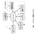
図2において、1は全体としてインターネットを利用した電子商取引を実現する本発明のコンテンツ提供システムを示し、コンテンツ制作者が使用するユーザPC(Personal Computer) 2と、当該ユーザPC2によって制作されたコンテンツを蓄え、要求に応じて提供するコンテンツ提供プロバイダ3と、Webサイト上で指定したコンテンツの提供をコンテンツ提供プロバイダ3から受ける複数のクライアントPC4(4A〜4N)と、コンテンツ制作者がユーザPC2を介してインターネット上でオンラインショッピングを行うためのオンライン通信販売会社6と、コマーシャル映像(以下、これをCM映像と呼ぶ)を作成し、当該CM映像をコンテンツ提供プロバイダ3からクライアントPC4へ提供するよう依頼するコマーシャルクライアント(以下、これをCMクライアントと呼ぶ)7とが互いにインターネット5を介して接続されている。
【0030】
このコンテンツ提供システム1は、ユーザPC2で制作された個人のコンテンツに対するクライアントPC4からのアクセス回数に応じて、コンテンツ提供プロバイダ3が受ける利益をコンテンツ制作者に正当に還元する(以下、これを利益還元と呼ぶ)システムであり、一段と優れたコンテンツの制作をコンテンツ制作者に促すと共に、Webサイトに対するクライアントPC4のアクセス回数を増加させることを目的とした、インターネット5上の全く新たなビジネスモデルを構築している。
【0031】
ここで、破線で囲われたコンテンツ提供プロバイダ3、オンライン通信販売会社6及びCMクライアント7は互いに提携関係にあってビジネスアライアンス8を構築しており、コンテンツ制作者(ユーザPC2)に対して様々な形態で利益還元処理を行うようになされている。
【0032】
(3)ユーザPCのユーザ登録手続き
このコンテンツ提供システム1においてユーザPC2は、まずコンテンツ提供プロバイダ3に対してユーザ登録手続きを行う必要があり、当該ユーザ登録手続きについて以下詳細に説明する。
【0033】
図3に示すように、ユーザPC2はバス11を介してCPU10、ハードディスクドライブ(HDD)12、RAM(Random Access Memory)13、IEEE(Institute of Electrical and Electronics Engineers) 1394インターフェース14、ネットワークインターフェース16及び液晶ディスプレイでなる表示部17が互いに接続されて構成されている。
【0034】
このようなユーザPC2においては、HDD12に基本プログラムであるOS(Operating System)の他、各種アプリケーションソフトウェアが格納されており、これらのアプリケーションソフトウェアをRAM13上に適宜立ち上げて所定の処理を実行するようになされている。
【0035】
すなわちユーザPC2は、図4に示すようにOSを起動することにより表示部17に表示したデスクトップ画面19(マイクロソフト社のウィンドウズ画面)のオンラインサインアップアイコン20がコンテンツ制作者によってクリックされると、CPU10がHDD12から自動オンラインサインアップソフトウェアを立ち上げることにより、図5に示すようなユーザ情報登録画面21を表示部17に表示する。
【0036】
このユーザ情報登録画面21は、画面タイトルにもあるようにパーソナルキャスティングサービスを申し込む際のユーザ情報を登録するためのものであり、コンテンツ制作者はこの画面に従って「氏名」、「住所」、「電話番号」、「電子メールアドレス」、「生年月日」、「クレジットカード番号」、「第1希望ユーザID」、「第2希望ユーザID」、「第3希望ユーザID」、「希望チャンネル名」、「パスワード」及び「パスワード確認」の入力を行い、最後に「申し込みサービス」を「使い放題コース」或いは「ビギナーコース」のいずれかから選択する。
【0037】
ここでパーソナルキャスティングサービスとは、本発明のコンテンツ提供システム1において新たに開始するコンテンツの提供形態であり、オンデマンド型及びライブ型と呼ばれるコンテンツの提供形態が用いられ、その内容については後程詳細に説明する。
【0038】
ユーザ情報登録画面21においては、コンテンツ制作者によって入力されたユーザ情報の内容を無効にするためのキャンセルボタン22と、コンテンツ制作者によって入力されたユーザ情報で申し込みを行うための申込みボタン23とが設けられている。
【0039】
従ってユーザPC2のCPU10は、ユーザ情報の入力が終了した後に申込みボタン23がクリックされると、図6に示すようにユーザ情報登録画面21(図5)と同一内容のユーザ情報ファイル25を作成し、これをネットワークインターフェース16(図3)からインターネット5(図2)を介してコンテンツ提供プロバイダ3に所定のプロトコルで送信すると共に、HDD12にユーザ情報ファイル25を書き込んで記憶しておく。
【0040】
コンテンツ提供プロバイダ3は、図7に示すようにユーザPC2をインターネット5に接続するためのインターネットサービスプロバイダ(以下、これをISPと呼ぶ)31と、ユーザPC2から供給されたコンテンツを蓄積し、クライアントPC4からの要求に応じて提供するアプリケーションサービスプロバイダ(以下、これをASPと呼ぶ)32とから構成されている。
【0041】
ISP31は、全体を統括管理する制御サーバ33と、ユーザPC2に対する課金管理を行う課金管理データベース34と、インターネット5を介してユーザPC2とのネットワーク接続を行うネットワークインターフェース35とが互いにLAN(Local Area Network)42を介して接続されており、制御サーバ33の制御に基づいて課金管理及びネットワーク制御を行うようになされている。
【0042】
ASP32は、全体を統括管理するための管理サーバ36と、ユーザPC2のユーザ情報ファイル25を管理するためのユーザ情報データベース37と、コンテンツの提供スケジュールを管理するための提供スケジュール管理データベース38と、コンテンツの蓄積及び提供を行うためのコンテンツサーバ39と、コンテンツの視聴者であるクライアントPC4(ビューワー)に関するビューワー情報を管理するためのビューワー情報データベース40と、CMクライアント7から供給されたCM映像をCM映像ID(Identification)に対応させて蓄積管理するためのCM管理データベース44とが互いにLAN43を介して接続されており、管理サーバ36の制御に基づいてユーザ情報管理、提供スケジュール管理、コンテンツの蓄積提供処理、ビューワー情報管理及びCM提供管理を行うようになされている。
【0043】
このコンテンツ提供プロバイダ3は、ユーザ登録手続きの際にユーザPC2から送信されたユーザ情報ファイル25をISP31のネットワークインターフェース35及びASP32のネットワークインターフェース41を介して管理サーバ36で受け取る。
【0044】
ASP32の管理サーバ36は、ユーザ情報ファイル25を受け取ると、内部のハードディスクから立ち上げたユーザ登録手続プログラムに従って、図8に示すルーチンRT1の開始ステップから入ってステップSP1に移る。
【0045】
ステップSP1においてASP32の管理サーバ36は、ユーザPC2から送信されたユーザ情報ファイル25の内容を読み出してクレジットカード番号の桁数をチェックし、正しい桁数であったときには次のステップSP2に移る。
【0046】
なおASP32の管理サーバ36は、クレジットカード番号が正しい桁数ではないとき、その旨をインターネット5を介してユーザPC2に通知し、正しい桁数のクレジットカード番号を入力するように促す。
【0047】
ステップSP2においてASP32の管理サーバ36は、ユーザ情報データベース37にアクセスし、送られてきたユーザ情報ファイル25のクレジットカード番号が重複していないかどうかをチェックし、重複していない場合にのみ次のステップSP3に移る。
【0048】
ステップSP3においてASP32の管理サーバ36は、ネットワークインターフェース41からインターネット5を介してクレジットカード会社の与信チェックサーバ26にアクセスし、そのクレジットカード番号が有効か否かの与信チェックを行い、当該クレジットカード番号が使用可能な状態であったときのみ次のステップSP4に移る。
【0049】
ステップSP4においてASP32の管理サーバ36は、ユーザ情報データベース37に再度アクセスし、ユーザ情報ファイル25の第1〜第3希望ユーザIDが既に使用されているか否かを調べ、第1〜第3希望ユーザIDのいずれかが未だ使用されていない場合、次のステップSP5に移る。
【0050】
ステップSP5においてASP32の管理サーバ36は、第1〜第3希望ユーザIDのうち希望順位の高い未使用のユーザIDを選定し、当該ユーザIDに対応したURL(Uniform Resource Locator)を決定した後、ユーザ情報ファイル25に基づいて図9に示すようなユーザ情報DBテーブル45を生成し、これをユーザ情報データベース37に新たに登録し、次のステップSP6に移る。
【0051】
ここでユーザ情報データベース37に新たに登録されたユーザ情報DBテーブル45には、ユーザ情報ファイル25の内容に加えてユーザIDに対応して決定されたURL、利益還元を受けるときに必要なコンテンツ制作者が獲得した累積ポイント数、当該累積ポイント数に応じたユーザのランクを表すユーザステータス(ステージ1)、接続開始日時、接続終了日時、現時点のインターネット5に対するISP31のインターネット接続料及びASP32の申込みサービス(「使い放題コース」)に対するサービス利用料が新たに追加されている。
【0052】
このようにASP32の管理サーバ36は、ユーザIDに対応したURLを決定した後ユーザ情報データベース37に登録することにより、個々のコンテンツ制作者が制作したコンテンツの動画像ファイルをURLに対応したコンテンツサーバ39の予め決められた専用の記憶領域に占有的に書き込む権利を与えるようになされている。
【0053】
またASP32の管理サーバ36は、ユーザ情報データベース37のユーザ情報DBテーブル45をコンテンツ制作者毎に管理するようになされており、クライアントPC4からのアクセス回数に応じてコンテンツ制作者の累積ポイント数を増加して更新し、当該累積ポイント数に応じてコンテンツ制作者のユーザステータスを変更したり、接続開始日時、接続終了日時、現在のインターネット接続料及び申込みサービスに対するサービス利用料に関する種々のデータを逐次更新する。
【0054】
因みにユーザステータスとは、累積ポイント数に応じたコンテンツ制作者に対する格付けで、低いほうから順にステージ1、ステージ2、プロフェッショナルステージと位置付けられるようになされている。従ってユーザステータスの高いコンテンツ制作者ほど、多くの利益還元を受けることが可能である。
【0055】
ステップSP6においてASP32の管理サーバ36は、選定したユーザIDと共に当該ユーザIDに対応したURLをネットワークインターフェース41からインターネット5を介してユーザPC2に通知する。
【0056】
このときASP32の管理サーバ36は、「ユーザIDに対応したURLに自動的に接続し、ユーザPC2で制作されたコンテンツの動画像ファイルをURLに対応したコンテンツサーバ39の専用の記憶領域に自動的に書き込む」ようにプログラムされた自動アップロードソフトウェアをシェアウエアとしてインターネット5を介してユーザPC2に対して供給するようになされている。
【0057】
これによりユーザPC2のCPU10は、自動アップロードソフトウェアをインターネット5を介してダウンロードし、当該自動アップロードソフトウェアに基づいてデスクトップ画面19(図4)に自動アップロードソフトウェアのアップロードアイコン27を表示する。
【0058】
そしてユーザPC2のCPU10は、デスクトップ画面19のアップロードアイコン27がコンテンツ制作者によってクリックされると、自動アップロードソフトウェアに従ってインターネット5からISP31を経由してASP32に接続し、当該ASP32の管理サーバ36に対して「URLに対応するコンテンツサーバ39の専用の記憶領域にコンテンツの動画像ファイルを自動的に書き込む」指示を与えるようになされている。
【0059】
これによりASP32の管理サーバ36は、ユーザPC2から供給されたコンテンツの動画像ファイルをURLに基づくコンテンツサーバ39の専用の記憶領域に書き込み、クライアントPC4からの要求に応じてコンテンツの動画像ファイルをコンテンツサーバ39の専用の記憶領域から読み出して提供することができる。
【0060】
このようにユーザPC2のCPU10は、コンテンツ制作者によるユーザ情報の登録手続きによってユーザIDが選定されると共にURLが決定され、ASP32から自動アップロードソフトウェアをダウンロードしてしまえば、URLをコンテンツ制作者に意識させたり入力させることなく、アップロードアイコン27に対するクリック操作だけで、制作したコンテンツの動画像ファイルをコンテンツサーバ39の専用の記憶領域にアップロードすることを一段と容易に実行し得るようになされている。
【0061】
この結果コンテンツ提供システム1においては、あたかも自分専用チャンネル(以下、これをマイチャンネルと呼ぶ)を介してコンテンツを提供する個人放送局を開設したかのようなシステムを構築し得るようになされている。
【0062】
ステップSP7においてASP32の管理サーバ36は、ユーザ登録手続き処理を完了したので、ユーザ登録完了通知メールを作成し、これをネットワークインターフェース41からインターネット5を介してユーザPC2に送信し、次のステップSP8でユーザ登録手続き処理を全て終了する。
【0063】
ところでASP32の管理サーバ36は、要求に応じて個人のユーザ情報DBテーブル45をビジネスアライアンスを構築しているISP31の制御サーバ33や、ユーザPC2からISP31のアクセスポイントまでの回線接続を行う電話会社(図示せず)及びオンライン通信販売会社6に対して送信するようになされている。
【0064】
この結果ISP31の制御サーバ33及びオンライン通信販売会社6もユーザ情報DBテーブル45を保持することになる。
【0065】
従ってユーザPC2は、ISP31、電話会社及びオンライン通信販売会社6等にアクセスする都度、コンテンツ制作者に対して面倒な登録手続きを強いることがなく、最初に行ったユーザ登録手続き処理だけで済むようになされている。
【0066】
因みにASP32の管理サーバ36は、ISP31の制御サーバ33、電話会社及びオンライン通信販売会社6に対して個人のユーザ情報DBテーブル45の内容を送信することに関して、ユーザ登録手続きのときに予めコンテンツ制作者に対して承諾をとるようになされている。
【0067】
(4)パーソナルキャスティングサービスの形態
本発明のコンテンツ提供システム1においては、上述したようにパーソナルキャスティングサービスによるコンテンツの提供形態としてオンデマンド型とライブ型とがある。
【0068】
オンデマンド型は、パーソナルキャスティングサービスのユーザ登録時に予めユーザPC2が取得したURLに対応するコンテンツサーバ39の専用の記憶領域に予めコンテンツを格納しておき、当該コンテンツサーバ39の専用の記憶領域を介して、要求のあったクライアントPC4に対してコンテンツを提供するサービス形態であり、あたかも個人放送局のように自分専用チャンネル(マイチャンネル)を介して要求のあったクライアントPC4にコンテンツを提供できるようにしたものである。
【0069】
一方ライブ型は、不特定多数のパーソナルキャスティングサービスの登録ユーザだけが特定ジャンルの映像チャンネル(例えば結婚式チャンネル、音楽ライブチャンネル、演劇ライブチャンネル及びイベントライブチャンネル)毎にURLで指定されたコンテンツサーバ39の専用の記憶領域を時間帯毎に区分けして共有使用し、当該コンテンツサーバ39の専用の記憶領域を介して、要求のあったクライアントPC4に対してライブ映像のコンテンツをストリーミング再生して送信することによりリアルタイムに提供するサービス形態である。
【0070】
このようにライブ型は、特定ジャンルの映像チャンネル毎にURLで指定されたコンテンツサーバ39の専用の記憶領域に対する使用時間帯枠を予約することにより不特定多数の登録ユーザが自由にコンテンツを提供し得るようになされており、あたかも公共的な映像チャンネル(以下、これをパブリックチャンネルと呼ぶ)を介して要求のあったクライアントPC4にライブ映像のコンテンツを提供できるようにしたものである。
【0071】
(5)オンデマンド型によるパーソナルキャスティングサービス
次に、コンテンツ提供システム1のオンデマンド型によるパーソナルキャスティングサービスの説明を具体的に行う。
【0072】
(5−1)オンデマンド型のコンテンツ制作処理
ユーザPC2(図3)のCPU10は、まずHDD12から画像取込ソフトウェアを起動することにより、図10に示すようなキャプチャー画面50を表示部17に表示する。
【0073】
この場合ユーザPC2のCPU10は、IEEE1394インターフェース14を介して接続されたディジタルビデオカメラ18と画像取込ソフトウェアによるキャプチャー画面50とを連動させるようになされており、コンテンツ制作者によるムービーモード切換ボタン53のクリック操作に応じてオンデマンドモードに設定する。
【0074】
そしてユーザPC2のCPU10は、ディジタルビデオカメラ18で撮影した映像をファインダ表示エリア51に表示してコンテンツ制作者に確認させると共に、当該コンテンツ制作者によるキャプチャーボタン52のクリック操作に基づいてディジタルビデオカメラ18による収録を開始し、キャプチャーボタン52の再クリック操作に基づいて収録を終了する。
【0075】
このときユーザPC2のCPU10は、キャプチャーボタン52のクリック操作に応じて収録したディジタルビデオカメラ18の動画像データをIEEE1394インターフェース14を介して取り込み、HDD12に一旦記録する。
【0076】
次にユーザPC2のCPU10は、図11に示すように画像取込ソフトウェアに従って確認画面55を表示部17に表示する。この確認画面55には、HDD12に一旦記録した動画像データを再生して表示する映像表示エリア56、再生中の動画像データに対するタイムコードを表示するタイムコード表示エリア57、収録時の日付を表示する日付表示エリア58、動画像データに対する再生、停止、早戻し、早送り等の操作を行う操作ボタン59、動画像データの一部又は全部をHDD12から削除する削除ボタン60及びOKボタン61が設けられており、確認画面55上で収録した動画像データのシーンをコンテンツ制作者に対して確認させて所望のシーンだけを残すように編集し得るようになされている。
【0077】
従って、収録した動画像データのシーンをコンテンツ制作者が確認画面55上で確認し編集した後、当該コンテンツ制作者がOKボタン61をクリックすると、ユーザPC2のCPU10は次にHDD12から編集ソフトウェアを起動することにより、図12に示すような編集画面65を表示部17に表示する。
【0078】
この編集画面65には、ディジタルビデオカメラ18で収録した動画像データの確認画面55を表示し得るようになされた3種類の確認画面表示エリア66〜68と、3種類の動画像データに対する合成順序を決定するための順番ボタン69と、決定された合成順序で3種類の動画像データを合成するための合成ボタン70と、OKボタン71とが設けられている。
【0079】
従ってユーザPC2のCPU10は、コンテンツ制作者による順番ボタン69のクリック操作によって3種類の動画像データに対する合成順序を決定し、合成ボタン70のクリック操作に応じて3種類の動画像データを合成順序に従って合成することにより動画像ファイルを生成し、当該動画像ファイルをASP32のコンテンツサーバ39に蓄積するコンテンツとしてHDD12に一旦格納するようになされている。
【0080】
(5−2)オンデマンド型のスケジュール予約
その後ユーザPC2のCPU10は、コンテンツ制作者によってOKボタン71がクリックされるか、デズクトップ画面19(図4)のアップロードアイコン27がクリックされると、ユーザ登録時にASP32から予めダウンロードした自動アップロードソフトウェアを起動し、図13に示すようなオンデマンド型パーソナルキャスト制御画面75を表示部17に表示する。
【0081】
このオンデマンド型パーソナルキャスト制御画面75には、モード表示欄76に現在オンデマンドモードが設定されていることを示す「オンデマンド」の文字が表示され、ISP名表示欄77にISP31の会社名が自動的に表示されると共に、ASPチャンネル表示欄78にオンデマンドモードで自動的に設定される「マイチャンネル」の文字が表示される。
【0082】
またオンデマンド型パーソナルキャスト制御画面75には、オプションボタン81が設けられており、当該オプションボタン81がコンテンツ制作者によってクリックされると、ユーザPC2のCPU10は自動アップロードソフトウェアに基づいて図14に示すようなプルダウンメニュー85をオンデマンド型パーソナルキャスト制御画面75に重ねて表示する。
【0083】
このプルダウンメニュー85には、コンテンツ制作者が制作したコンテンツの映像ジャンルを指定するためのジャンル設定ボタン85A、要求のあったクライアントPC4に対してコンテンツを提供する際のコーデックを選択するコーデック選択ボタン85B、コンテンツの提供スケジュールをコンテンツ制作者によって自由に決定するためのスケジュール予約ボタン85C、コンテンツ制作者の希望によりコンテンツの先頭部分にCM映像を付加してクライアントPC4に提供するためのCM提供リクエストボタン85D、CM映像から例えばCM提供会社のホームページにリンクするためのCMリンク設定ボタン85E及びコンテンツに対応したコンテンツIDを設定するためのコンテンツID設定ボタン85Fが設けられている。
【0084】
このようなプルダウンメニュー85のうちジャンル設定ボタン85Aがコンテンツ制作者によってクリックされると、ユーザPC2のCPU10は自動アップロードソフトウェアに基づいて図15に示すようなマイチャンネルジャンル表画面90を表示部17に表示する。
【0085】
マイチャンネルジャンル表画面90には、コンテンツの映像ジャンルをコンテンツ制作者が指定するために、映像カテゴリ毎にそれぞれ区分けされたカテゴリアイコン91〜99が表示され、そのうちのいずれか(例えば「車」カテゴリアイコン92)がコンテンツ制作者によってクリックされると、ユーザPC2のCPU10はコンテンツの映像ジャンルを「車」であると認識し、当該認識した結果をカテゴリデータとしてHDD12に一旦記憶する。
【0086】
また、プルダウンメニュー85のうちコーデック選択ボタン85Bがコンテンツ制作者によってクリックされると、ユーザPC2のCPU10は自動アップロードソフトウェアに基づいて図16に示すようなコーデック選択画面100を表示部17に表示する。
【0087】
このコーデック選択画面100では、クライアントPC4に対してコンテンツを提供する際のコーデックとして例えばMPEG(Moving Picture Experts Group)4、MPEG2及びRealG2等のいずれかから選択するようになされており、コンテンツ制作者によって例えばMPEG4にチェックマークが付けられると、ユーザPC2のCPU10はコーデックの種類をMPEG4であると認識し、当該認識した結果をコーデック種類データとしてHDD12に一旦記憶する。
【0088】
さらに、プルダウンメニュー85のうちスケジュール予約ボタン85Cがコンテンツ制作者によってクリックされると、ユーザPC2のCPU10は自動アップロードソフトウェアに基づいて図17に示すようなオンデマンド型提供スケジュール管理画面105を表示部17に表示する。
【0089】
このオンデマンド型提供スケジュール管理画面105には、カレンダ表示エリア106、映像リスト表示エリア107、スケジュール内容表示エリア108、決定ボタン109、スケジュール内容確認ボタン110及びスケジュール内容更新ボタン111が設けられている。
【0090】
このオンデマンド型提供スケジュール管理画面105のカレンダ表示エリア106において、コンテンツを提供する所望の提供日(例えば2月19日)がコンテンツ制作者のクリック操作によって選択されると、ユーザPC2のCPU10はコンテンツ制作者が希望する提供日を2月19日であると認識し、その結果2月19日を提供日データとしてHDD12に一旦記憶すると共に、スケジュール表示エリア108のタイトルに提供日(2月19日)を自動的に書き込んで表示する。
【0091】
そしてオンデマンド型提供スケジュール管理画面105のスケジュール内容表示エリア108において、所望の開始時刻と終了時刻に合わせてクリックすることにより時間帯指定バー112がコンテンツ制作者によって指定されると、ユーザPC2のCPU10は開始時刻から終了時刻までの時間帯枠を認識すると共に時間帯指定バー112をコンテンツ制作者によって指定された時間帯枠毎に区分けして表示する。
【0092】
すなわちスケジュール内容表示エリア108の時間帯指定バー112は、6時から6時59分59秒までの第1の時間帯枠と、7時から7時59分59秒までの第2の時間帯枠と、8時から8時59分59秒までの第3の時間帯枠と、9時から10時59分59秒までの第4の時間帯枠と、……、21時から21時59分59秒までの第5の時間帯枠と、22時から23時59分59秒までの第6の時間帯枠とに区分けされて表示される。
【0093】
続いて、コンテンツ制作者がクリックすることにより時間帯指定バー112における所望の時間帯枠が選択され、映像リスト表示エリア107の中から所望の映像種類(例えば4WD、スポーツカー、電気自動車)を示す種類記号(MA、MB又はMC)がクリックされると、ユーザPC2のCPU10は選択された第1〜第6の時間帯枠でそれぞれ提供するコンテンツの映像種類を種類記号(MA、MB又はMC)によって認識し、当該認識した種類記号を時間帯指定バー112の時間帯枠内にそれぞれ表示する。
【0094】
そしてオンデマンド型提供スケジュール管理画面105で決定ボタン109がクリックされると、ユーザPC2のCPU10は時間帯指定バー112における第1〜第6の時間帯枠毎に決められた映像種類でコンテンツを提供するように予約した提供スケジュールプログラムを生成し、これをHDD12に一旦記憶する。
【0095】
すなわち提供スケジュールプログラムは、時間帯指定バー112における第1の時間帯枠の時刻でクライアントPC4から要求を受けると種類記号MAに該当する「4WD」のコンテンツを提供し、第2の時間帯枠の時刻でクライアントPC4から要求を受けると種類記号MBに該当する「スポーツカー」のコンテンツを提供し、第3の時間帯枠の時刻でクライアントPC4から要求を受けると種類記号MAに該当する「4WD」のコンテンツを提供し、第4の時間帯枠の時刻でクライアントPC4から要求を受けると種類記号MCに該当する「セダン」のコンテンツを提供し、第5の時間帯枠の時刻でクライアントPC4から要求を受けると種類記号MBに該当する「スポーツカー」のコンテンツを提供し、第6の時間帯枠の時刻でクライアントPC4から要求を受けると種類記号MAに該当する「4WD」のコンテンツを提供するようにプログラムされている。
【0096】
さらに、プルダウンメニュー85(図14)のうちCM提供リクエストボタン85Dがコンテンツ制作者によってクリックされると、ユーザPC2のCPU10は自動アップロードソフトウェアに基づいて図18に示すようなCM提供リクエスト画面115を表示部17に表示する。
【0097】
このCM提供リクエスト画面115には、自分のコンテンツの先頭部分にCM映像を付加してクライアントPC4に提供することを希望するか否かをコンテンツ制作者に対して問うためのCM希望ボタン115A及びCM非希望ボタン115Bが設けられており、CM希望ボタン115Aがコンテンツ制作者によってクリックされたときのみ、ユーザPC2のCPU10はコンテンツに対してCM映像を付加してもらうことを希望する旨のCM希望データを生成し、これをHDD12に一旦記憶する。
【0098】
さらに、プルダウンメニュー85のうちCMリンク設定ボタン85Eがコンテンツ制作者によってクリックされると、ユーザPC2のCPU10は自動アップロードソフトウェアに基づいて図19に示すようなCMリンク設定画面116を表示部17に表示する。
【0099】
このCMリンク設定画面116には、コンテンツの最初に付加したCM映像から例えばCM提供会社のホームページにリンクするアンカを設定するためのCMリンク有ボタン116Aと、CM映像からのリンクを設定しないためのCMリンク無ボタン116Bとが設けられており、CMリンク有ボタン116Aがコンテンツ制作者によってクリックされたときのみ、ユーザPC2のCPU10はCM映像から所定のホームページにリンクするアンカの設定を希望する旨のCMリンクデータを生成し、これをHDD12に一旦記憶する。
【0100】
さらに、プルダウンメニュー85のうちコンテンツID設定ボタン85Fがコンテンツ制作者によってクリックされると、ユーザPC2のCPU10は自動アップロードソフトウェアに基づいて図20に示すようなコンテンツID設定画面117を表示部17に表示する。
【0101】
このコンテンツID設定画面117には、コンテンツID入力欄117Aが設けられており、コンテンツ制作者によってコンテンツに対応した任意のコンテンツIDが入力されて実行キーが押下されると、ユーザPC2のCPU10はコンテンツIDを認識し、これをHDD12に一旦記憶する。
【0102】
このようにユーザPC2のCPU10は、パーソナルキャスト制御画面75のオプションボタン81をクリックすることにより表示されたプルダウンメニュー85に従ってコンテンツを提供する際の種々の条件を設定し、HDD12に一旦記憶した種々の諸条件データ(カテゴリデータ、コーデック種類データ、提供スケジュールプログラム、CM希望データ、CMリンクデータ及びコンテンツID)やユーザ登録手続き処理を行った際のユーザ情報ファイル25の内容に基づいて図21に示すようなオンデマンド型提供スケジュールコントロールファイル120を新たに生成し、これをHDD12に一旦記憶するようになされている。
【0103】
すなわちHDD12に一旦記憶されたオンデマンド型提供スケジュールコントロールファイル120には、「ISP接続先」としてインターネット5に接続する際のISP名(*****)、「ASPチャンネル」としてASP32がコンテンツを提供する際のチャンネルタイプ(マイチャンネル)、「コンテンツID」としてコンテンツ制作者が決定したコンテンツID(***)、「CODEC」として提供時のCODEC(MPEG4)、「映像ジャンル」として映像カテゴリ(車)、「提供スケジュール」として提供スケジュールデータの内容(2月19日6時から提供予定等の諸条件)、「CMリクエスト」としてCM提供リクエストの有無(CM有)、「CMリンク」としてCMリンクの有無(CMリンク無)、「ユーザID」としてユーザ登録時のユーザID(kimkim) 、「パスワード」としてユーザ登録時のパスワード(*****)が格納されている。
【0104】
従ってユーザPC2のCPU10は、オンデマンド型提供スケジュールコントロールファイル120に基づいてオンデマンド型パーソナルキャスト制御画面75(図13)の映像ジャンル表示欄79にコンテンツの映像カテゴリを表す「車」の文字を表示すると共に、提供スケジュール予約表示欄80にコンテンツの提供予定を表す「2月19日6時から提供予定」の文字を表示するようになされている。
【0105】
なお、CMリンク設定及びコンテンツID設定はユーザPC2によりプルダウンメニュー85を用いて設定する旨説明したが、ASP32の管理サーバ36側で自動的に設定されるようにしても良い。
【0106】
例えばCMリンク設定は、クライアントPC4により提供されることが決まったCMに対して、リンク指定がCMクライアント7によって予め行われているときは自動的にCMリンクが行われる。
【0107】
また、例えば画像のアップロードが行われるとASP32の管理サーバ36側で自動的にコンテンツIDが設定され、このIDによりASP32の管理サーバ36上で管理されることも可能である。
【0108】
(5−3)オンデマンド型におけるASPへのコネクト処理
次にユーザPC2のCPU10は、オンデマンド型パーソナルキャスト制御画面75(図13)の内容がコンテンツ制作者によって確認され、当該コンテンツ制作者によってコネクトボタン82がクリックされると、自動アップロードソフトウェアに従って図22に示すルーチンRT2の開始ステップから入ってステップSP11に移る。
【0109】
ステップSP11においてユーザPC2のCPU10は、ネットワークインターフェース16(図3)からインターネット5及びISP31を介してASP32にログインし、当該ASP32のユーザ情報データベース37にアクセスしてユーザID、パスワード等を基に認証を得た後、次のステップSP12に移る。
【0110】
ステップSP12においてユーザPC2のCPU10は、ASP32の認証を得たので、HDD12からオンデマンド型提供スケジュールコントロールファイル120とコンテンツの動画像ファイルとを読み出した後、当該オンデマンド型提供スケジュールコントロールファイル120とコンテンツの動画像ファイルとをネットワークインターフェース16からインターネット5、ISP31のネットワークインターフェース35及びASP32のネットワークインターフェース41を経由して管理サーバ36へ転送し、次のステップSP13に移って処理を終了する。
【0111】
このようにしてユーザPC2のCPU10は、自動アップロードソフトウェアに従ってオンデマンド型提供スケジュールコントロールファイル120及びコンテンツの動画像ファイルをASP32にアップロードし得るようになされている。
【0112】
ASP32の管理サーバ36は、ネットワークインターフェース41を介してオンデマンド型提供スケジュールコントロールファイル120及びコンテンツの動画像ファイルを受け取り、オンデマンド型提供スケジュールコントロールファイル120を提供スケジュール管理データベース38に登録し、コンテンツの動画像ファイルをユーザPC2がユーザ登録時に取得したURLに対応するコンテンツサーバ39の専用の記憶領域に格納する。
【0113】
なおASP32の管理サーバ36は、オンデマンド型提供スケジュールコントロールファイル120の内容としてCM提供リクエストが「CM有」の場合、CMクライアント7から予め供給されてCM管理データベース44に格納しておいたCM映像をコンテンツの動画像ファイルの先頭部分に付加することによりCM付動画像ファイルを生成し、これをコンテンツサーバ39に改めて格納しておくようになされている。
【0114】
ところでISP31の制御サーバ33は、ユーザPC2がオンデマンド型提供スケジュールコントロールファイル120及びコンテンツの動画像ファイルをASP32にアップロードしている間に発生するインターネット接続料をユーザPC2のユーザIDに対応付けて課金し、課金管理データベース34の課金データを更新する。
【0115】
またASP32の管理サーバ36は、当該ASP32のサービス利用料をユーザPC2のユーザIDに対応付けて課金し、その課金データをネットワークインターフェース41及びISP31のネットワークインターフェース35を介して課金管理データベース34に送信し、課金管理データベース34の課金データを更新する。
【0116】
因みにASP32の管理サーバ36は、ユーザPC2が「使い放題コース」と呼ばれる定額制のサービス契約がなされている場合、接続開始日時から接続終了日時までの接続時間をユーザ情報データベース37に記録するだけでサービス利用料は一定のままで課金処理は行わない。
【0117】
ところで、オンデマンド型提供スケジュールコントロールファイル120及びコンテンツの動画像ファイルのASP32に対するアップロードが終了した後、オンデマンド型提供スケジュールコントロールファイル120の内容を確認したい場合、コンテンツ制作者はオンデマンド型提供スケジュール管理画面105(図17)のスケジュール内容確認ボタン110をクリックすれば良い。
【0118】
このときユーザPC2のCPU10は、自動アップロードソフトウェアに従って図23に示すルーチンRT3の開始ステップから入ってステップSP15に移る。
【0119】
ステップSP15においてユーザPC2のCPU10は、コンテンツ制作者によってスケジュール内容確認ボタン110がクリックされると、ネットワークインターフェース16(図3)からインターネット5及びISP31を介してASP32にログイン処理し、当該ASP32のユーザ情報データベース37にアクセスしてユーザID、パスワード等の認証を得、次のステップSP16に移る。
【0120】
ステップSP16においてユーザPC2のCPU10は、ASP32の管理サーバ36によってユーザID、パスワード等の認証を得たので、提供スケジュール管理データベース38からオンデマンド型提供スケジュールコントロールファイル120の供給を受け、当該オンデマンド型提供スケジュールコントロールファイル120に基づいてオンデマンド型提供スケジュール管理画面105(図17)を表示部17に再度表示する。
【0121】
このようにユーザPC2のCPU10は、オンデマンド型提供スケジュール管理画面105を表示部17の画面上に表示することにより、コンテンツ制作者に対してオンデマンド型提供スケジュールコントロールファイル120の内容を再度確認させ得るようになされている。
【0122】
この後コンテンツ制作者が、オンデマンド型提供スケジュールコントロールファイル120の内容を変更しようとした場合、オンデマンド型提供スケジュール管理画面105上で提供スケジュールの変更が行われた後に決定ボタン109がクリックされると、ユーザPC2のCPU10は次のステップSP17に移る。
【0123】
ステップSP17においてユーザPC2のCPU10は、オンデマンド型提供スケジュール管理画面105上で変更された内容に基づいて新たな提供スケジュールプログラムを生成し、これを基に新たなオンデマンド型提供スケジュールコントロールファイル120を生成し、次のステップSP18に移る。
【0124】
ステップSP18においてユーザPC2のCPU10は、オンデマンド型提供スケジュール管理画面105上の更新ボタン111がコンテンツ制作者によってクリックされると、新たなオンデマンド型提供スケジュールコントロールファイル120をインターネット5を介してASP32へ転送し、次のステップSP19に移って処理を終了する。
【0125】
この結果ASP32の管理サーバ36は、新たなオンデマンド型提供スケジュールコントロールファイル120で提供スケジュール管理データベース38を更新し、以降この新たなオンデマンド型提供スケジュールコントロールファイル120に基づいてコンテンツの提供スケジュールを管理するようになされている。
【0126】
(5−4)オンデマンド型におけるコンテンツの提供処理
クライアントPC4においても、コンテンツの提供を受けるに当たってユーザPC2と同様に、コンテンツ提供プロバイダ3に対してユーザ登録が可能であり、その場合にはルーチンRT1(図8)のユーザ登録手続き処理手順に従ってユーザ登録手続きを行い、ASP32の管理サーバ36によってビューワー情報データベース40にクライアントPC4のユーザID及びパスワードに対応付けられたビューワー情報ファイルの登録が行われる。
【0127】
またクライアントPC4は、ユーザ登録を行っていない場合にはビジターとしてASP32が提供するパーソナルキャスティングサービスのWebサイトに直接アクセスしてもよく、ユーザ登録したクライアントPC4に限っては感動や共感を覚えたり、あるいは優れていると感じたコンテンツのコンテンツ制作者に対して容易に寄付を行えるようになされている。この寄付に関しては後程説明する。
【0128】
実際上、ASP32の管理サーバ36は、例えばユーザ登録を行ったクライアントPC4に対してオンデマンド型でコンテンツを提供する場合、内部のハードディスクから立ち上げたコンテンツ提供プログラムに従って図24に示すルーチンRT4の開始ステップから入ってステップSP21に移る。
【0129】
ステップSP21においてASP32の管理サーバ36は、クライアントPC4からのログイン処理を受け、当該クライアントPC4から送られてきたユーザID及びパスワードを基にビューワー情報データベース40のビューワー情報ファイルを参照し、次のステップSP22に移る。
【0130】
ステップSP22においてASP32の管理サーバ36は、ユーザID及びパスワードを基にビューワー情報データベース40のビューワー情報ファイルを参照した結果、ログインしてきたクライアントPC4が登録済の正規ユーザであるか否かを判定する。
【0131】
ここで否定結果が得られると、このことはユーザID及びパスワードがビューワー情報データベース40に登録されたものと一致しないことを表しており、このときASP32の管理サーバ36はステップSP21に戻って、クライアントPC4に対して正確なユーザID及びパスワードの入力を促してログイン処理を再実行させる。
【0132】
これに対してステップSP22で肯定結果が得られると、このことはクライアントPC4が登録済の正規ユーザであることを表しており、このときASP32の管理サーバ36は次のステップSP23に移る。
【0133】
ステップSP23においてASP32の管理サーバ36は、クライアントPC4からのアクセスに応じてパーソナルキャスティングサービスにおけるホームページのHTMLファイルをコンテンツサーバ39から読み出し、これをネットワークインターフェース41からインターネット5を介してクライアントPC4へ送信する。
【0134】
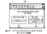
ここでクライアントPC4は、ユーザPC2(図3)とほぼ同一の構成を有し、ASP32から送られてきたパーソナルキャスティングサービスにおけるホームページのHTMLファイルをCPU(図示せず)が受け取り、これを図25に示すようなホームページ画面125(ネットスケープコミュニケーション社のネットスケープナビゲータ画面)として表示部に表示する。
【0135】
このホームページ画面125には、オンデマンドモード選択表示エリア126にマイチャンネルを介してコンテンツの提供を受けるためのオンデマンド型マイチャンネル選択ボタン127が設けられていると共に、ライブモード選択表示エリア128にライブ映像のコンテンツの提供をパブリックチャンネルを介して受けるためのライブ型パブリックチャンネル選択ボタン129と、ライブ映像のコンテンツの提供をマイチャンネルを介して受けるためのライブ型マイチャンネル選択ボタン130とが設けられている。
【0136】
このホームページ画面125において、オンデマンド型マイチャンネル選択ボタン127がユーザによってクリックされると、クライアントPC4のCPUはオンデマンド型マイチャンネル選択ボタン127が選択されたことを示すモード選択信号をインターネット5を介してASP32の管理サーバ36に送信する。
【0137】
ステップSP24において管理サーバ36は、クライアントPC4から送られたモード選択信号に基づいてコンテンツサーバ39からマイチャンネル用のジャンル表画面を構成するHTMLファイルを読み出し、これをネットワークインターフェース41からインターネット5を介してクライアントPC4へ送信する。
【0138】
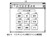
これによりクライアントPC4のCPUは、ASP32から送られてきたマイチャンネル用のジャンル表画面のHTMLファイルを受け取り、これを図26に示すようなマイチャンネル用のジャンル表画面135として表示部に表示する。
【0139】
このマイチャンネル用のジャンル表画面135は、コンテンツ制作者がコンテンツの映像ジャンルを選択するときに用いたマイチャンネル用のジャンル表画面90(図15)とほぼ同一内容であり、映像カテゴリ毎に区分けされたカテゴリアイコン136〜144が表示されている。
【0140】
このようなマイチャンネル用のジャンル表画面135において、カテゴリアイコン136〜144のいずれか(例えば「車」カテゴリアイコン137)がクライアントPC4のユーザによってクリックされると、当該クライアントPC4のCPUは「車」カテゴリアイコン137に対応したジャンル選択信号をインターネット5を介してASP32の管理サーバ36に送信する。
【0141】
ステップSP25においてASP32の管理サーバ36は、クライアントPC4から送られたジャンル選択信号に基づいてコンテンツサーバ39から映像カテゴリ「車」に関するチャンネル表示画面のHTMLファイルを読み出し、これをネットワークインターフェース41からインターネット5を介してクライアントPC4へ送信する。
【0142】
これによりクライアントPC4のCPUは、ASP32から送られてきたチャンネル表示画面のHTMLファイルを受け取り、これを図27に示すように映像ジャンル「車」に関するチャンネル表示画面150として表示部に表示する。
【0143】
このチャンネル表示画面150には、コンテンツ制作者がユーザ登録処理を行ったときのユーザ情報DBテーブル45(図9)に設定したチャンネル名(木村Ch)が付けられたチャンネルボタン151〜159がそれぞれ表示されており、ユーザはこの中から所望のチャンネルボタン(例えば木村Ch)155をクリックして選択するようになされている。
【0144】
ステップSP26においてASP32の管理サーバ36は、チャンネル表示画面150を見ているクライアントPC4のユーザによって所望のチャンネルボタン155がクリックされて選択されたか否かを判定する。
【0145】
この場合、クライアントPC4のCPUは、ユーザによって選択されたチャンネルボタン155に対応して設定されているコンテンツIDをインターネット5を介してASP32の管理サーバ36に送信するようになされている。
【0146】
従ってASP32の管理サーバ36は、コンテンツIDを受け取った場合に所望のチャンネルボタン155がクリックされたものとして認識し、コンテンツIDに基づいて提供スケジュール管理データベース38に格納されているオンデマンド型提供スケジュールコントロールファイル120を参照し、チャンネルボタン155に対応したURLを把握するようになされている。
【0147】
このステップSP26で否定結果が得られると、このことはチャンネル表示画面150に表示されているチャンネルボタン151〜159のいずれもユーザによって選択されていないことを表しており、このときASP32の管理サーバ36はチャンネルボタン151〜159のいずれかが選択されるまで待ち受ける。
【0148】
これに対してステップSP26で肯定結果が得られると、このことはチャンネルボタン151〜159のうちユーザ所望のチャンネルボタン155がクリックされて選択されたことを表しており、このときASP32の管理サーバ36は次のステップSP27に移る。
【0149】
ステップSP27においてASP32の管理サーバ36は、クリックされたチャンネルボタン(例えば木村Ch)155に対応したコンテンツIDをクライアントPC4からインターネット5を介して受けると、当該コンテンツIDに基づいてオンデマンド型提供スケジュールコントロールファイル120を参照し、チャンネルボタン155がクリックされた時点のタイミングで提供予定にある映像種類(MA、MB又はMC)のCM付動画像ファイルを、コンテンツIDに対応したURLに基づいてコンテンツサーバ39の専用の記憶領域から読み出し、これをインターネット5を介してクライアントPC4へ送信し、次のステップSP28に移って処理を終了する。
【0150】
実際上、チャンネル表示画面150において、例えばユーザによって2月19日の午前10時55分にチャンネルボタン(例えば木村Ch)155がクリックされると、ASP32の管理サーバ36はオンデマンド型提供スケジュールコントロールファイル120を参照し、オンデマンド型提供スケジュール管理画面105(図17)で指定したスケジュール内容表示エリア108の提供スケジュールに従って、映像種類が「セダン(MC)」のCM付動画像ファイルをクライアントPC4へ送信する。
【0151】
これによりクライアントPC4は、受信したCM付動画像ファイルに基づいて図28に示すようなコンテンツ表示画面165を表示部に表示し、当該コンテンツ表示画面165の中央に設けられた表示エリア166にCM映像を最初に表示した後、続いて「セダン」の車の動画像を表示する。
【0152】
このようにASP32の管理サーバ36は、オンデマンド型提供スケジュールコントロールファイル120の内容に従ってクライアントPC4のユーザによってチャンネルボタン151〜159がクリックされた時点のタイミングで提供予定にある1種類のCM付動画像ファイルをクライアントPC4へ送信するようになされている。
【0153】
これによりASP32の管理サーバ36は、ほぼ同時に複数のクライアントPC4から同一のコンテンツに対する要求を受けて送信する場合でも、あるタイミングで複数種類のコンテンツを同時に送信しなければならない場合と比較すれば、伝送路の帯域幅を多く消費せずに済むのでコンテンツを滞らせることなく速やかに伝送し得るようになされている。
【0154】
また、このときASP32の管理サーバ36は、クリック操作に応じてクライアントPC4へコンテンツのCM付動画像ファイルを提供する度に、クライアントPC4のクリック回数をアクセス回数としてカウントする。
【0155】
この場合、カウントしたアクセス回数がCM映像を視聴させた人数に相当するので、ASP32の管理サーバ36はアクセス回数の多いコンテンツを制作したコンテンツ制作者に対して正当に利益還元するために、アクセス回数に応じたポイントをコンテンツ制作者に与えるようになされており、そのコンテンツ制作者に対するポイントをユーザIDに対応したユーザ情報DBデーブル45に登録してユーザ情報データベース37に格納するようになされている。
【0156】
(6)ライブ型によるパーソナルキャスティングサービス
次にコンテンツ提供システム1のライブ型によるパーソナルキャスティングサービスの説明を具体的に行う。
【0157】
(6−1)ライブ型のスケジュール予約
ライブ型においては、ライブ映像のコンテンツをリアルタイムに提供するため、オンデマンド型のようにコンテンツの動画像ファイルを作成し、当該作成したコンテンツの動画像ファイルを予めASP32のコンテンツサーバ39に蓄積しておく必要はない。
【0158】
但しライブ型では、共用のパブリックチャンネル(結婚式チャンネル、音楽ライブチャンネル、演劇ライブチャンネル又はイベントライブチャンネル)を介してコンテンツを提供するようになされているので、予めパブリックチャンネルを使用する時間帯枠を予約しておく必要がある。
【0159】
すなわちパブリックチャンネルを使用する時間帯枠を予約するということは、各パブリックチャンネルのURLに対応して割り当てられたコンテンツサーバ39の専用の記憶領域を使用する時間帯枠の予約を行うことである。
【0160】
実際上ASP32がライブ映像のコンテンツを提供する場合、各パブリックチャンネル毎にURLで指定されたコンテンツサーバ39の専用の記憶領域にユーザPC2から送られてきたライブ映像の動画像ファイルを一旦書き込みながら読み出して出力するようになされている。
【0161】
すなわちユーザPC2のCPU10は、パブリックチャンネルを使用する時間帯枠の予約を行うために、まずオンデマンド型の場合と同様に画像取込ソフトウェアを起動することによりキャプチャー画面50(図10)を表示部17に表示する。
【0162】
そしてユーザPC2のCPU10は、キャプチャー画面50におけるムービーモード切換ボタン53のクリック操作に応じてライブモードに設定した後、ユーザ登録時にASP32から予めダウンロードしておいた自動アップロードソフトウェアを起動し、図13との対応部分に同一符号を付して示す図29のようなライブ型パーソナルキャスト制御画面170を表示部17に表示する。
【0163】
ライブ型パーソナルキャスト制御画面170には、モード表示欄171に現在ライブモードが設定されていることを示す「ライブ」の文字が表示され、ASPチャンネル表示欄172にライブモードでデフォルトとして設定されている「パブリックチャンネル」の文字が表示されると共に、オンデマンド型パーソナルキャスト制御画面75(図13)のオプションボタン81に変わってスケジュール予約ボタン173が設けられている。
【0164】
またライブ型パーソナルキャスト制御画面170には、パブリックチャンネルとして設定されている4種類の結婚式チャンネル、音楽ライブチャンネル、演劇ライブチャンネル及びイベントライブチャンネルの中から、コンテンツ制作者によって時間帯枠を予約した時に決定されたパブリックチャンネルの名称(例えば「音楽ライブ」)が映像ジャンル表示欄79に表示されるようになされている。
【0165】
さらにライブ型パーソナルキャスト制御画面170には、オンデマンド型と同様に提供スケジュール予約表示欄80に、コンテンツ制作者によって予約されたライブ映像のコンテンツの提供予定日時が表示されるようになされている。
【0166】
このようなライブ型パーソナルキャスト制御画面170において、スケジュール予約ボタン173がコンテンツ制作者によってクリックされると、ユーザPC2のCPU10はASP32からダウンロードした自動アップロードソフトウェアを起動し、図30に示すルーチンRT5の開始ステップから入ってステップSP31に移る。
【0167】
ステップSP31においてユーザPC2のCPU10は、ネットワークインターフェース16(図3)からインターネット5及びISP31を介してASP32にログインし、当該ASP32のユーザ情報データベース37にアクセスしてユーザID、パスワード等を基に認証を得た後、次のステップSP32に移る。
【0168】
ステップSP32においてユーザPC2のCPU10は、ASP32の管理サーバ36によって提供スケジュール管理データベース38から読み出されたパブリックチャンネルの予約状況に関するライブ型提供スケジュールコントロールファイルをインターネット5を介して受け取り、これをHDD12に書き込んだ後、次のステップSP33に移る。
【0169】
ステップSP33においてユーザPC2のCPU10は、ASP32から供給されたパブリックチャンネルの予約状況に関するライブ型提供スケジュールコントロールファイルに基づいて図31に示すようなパブリックチャンネル用のライブ型提供スケジュール管理画面175を表示部17に表示し、次のステップSP34で処理を終了する。
【0170】
このライブ型提供スケジュール管理画面175には、パブリックチャンネルとして4種類の結婚式チャンネル、音楽ライブチャンネル、演劇ライブチャンネル及びイベントライブチャンネルに対応する結婚式Chボタン176、音楽ライブChボタン177、演劇ライブChボタン178及びイベントライブChボタン179が設けられている。
【0171】
これら4種類のパブリックチャンネルのうち例えば音楽ライブChボタン177がコンテンツ制作者によってクリックされると、ユーザPC2のCPU10はライブ型提供スケジュールコントロールファイルに基づいてスケジュール内容表示エリア180に「音楽ライブチャンネル」に関する現在の予約状況を表示する。
【0172】
このときスケジュール内容表示エリア180のスケジュール時刻予定表182には、デフォルトとして今日現在の日付に関する予約状況が表示されるようになされており、コンテンツ制作者によってカレンダ表示エリア181の予約希望日(例えば2月19日)がクリックされると、ユーザPC2のCPU10はライブ型提供スケジュールコントロールファイルに基づいて音楽ライブチャンネルに関する予約希望日(2月19日)の予約状況をスケジュール時刻予定表182に表示する。
【0173】
コンテンツ制作者は、スケジュール時刻予定表182に表示された予約希望日(2月19日)の予約状況を確認し、時間帯指定バー183のうち「空」時間帯の中から所望の開始時刻(例えば10時)と終了時刻(10時59分59秒)をカーソルで指定することにより、ライブ映像のコンテンツを提供する時間帯枠183Aを決定する。
【0174】
これによりユーザPC2のCPU10は、コンテンツ制作者によって決定された時間帯枠183Aが示す開始時刻と終了時刻を予約時間帯枠データとして認識し、ライブ型提供スケジュールコントロールファイルに書き加えると共に、当該時間帯枠183Aに「満」の文字を表示する。
【0175】
またユーザPC2のCPU10は、予約された時間帯枠183Aで提供するコンテンツの名称(例えば「××ツアー」)がコンテンツ制作者によって入力されると、その名称を自動的に所定のコンテンツIDに対応付けてライブ型提供スケジュールコントロールファイルに書き加えるようになされている。
【0176】
続いてユーザPC2のCPU10は、コーデック選択表示エリア184の中からライブ映像のコンテンツをクライアントPC4に提供する際のコーデックとして例えばMPEG4にチェックマークが付けられると、選択されたコーデックの種類をMPEG4であると認識し、当該認識した結果をコーデック種類データとしてライブ型提供スケジュールコントロールファイルに書き加える。
【0177】
またユーザPC2のCPU10は、コンテンツの先頭部分にCM映像を付加してクライアントPC4に提供することを希望するCM希望ボタン185と、CM映像をクライアントPC4に提供することを希望しないCM非希望ボタン186とのうち、コンテンツ制作者によってCM希望ボタン185がクリックされると、ライブ映像のコンテンツに対してCM映像を付加することを希望したCM希望データ生成し、これをライブ型提供スケジュールコントロールファイルに書き加える。
【0178】
このようにユーザPC2のCPU10は、上述のようにパブリックチャンネルとして音楽ライブチャンネルを介してライブ映像のコンテンツを提供するための各種設定を行うことにより、図32に示すようなライブ型提供スケジュールコントロールファイル189を新たに生成し、これをHDD12に一旦記憶する。
【0179】
このライブ型提供スケジュールコントロールファイル189には、「ISP接続先」としてインターネット5に接続する際のISP名(*****)、「ASPチャンネル」としてASPがライブ映像のコンテンツを提供する際のチャンネルタイプ(パブリックチャンネル)、「コンテンツ名称」としてコンテンツのタイトル(××ツアー)、「CODEC」として提供時のCODEC(MPEG4)、「パブリックチャンネル」としてコンテンツ制作者によってライブ映像の内容に合わせて選択されたパブリックチャンネルの種類(音楽ライブチャンネル)、「提供スケジュール」として提供スケジュールの日時(2月19日10時から提供予定等の諸条件)、「CMリクエスト」としてCM提供リクエストの有無(CM有)、「ユーザID」としてユーザ登録時のユーザID(kimkim)、「パスワード」としてユーザ登録時のパスワード(*****)が格納されている。
【0180】
そしてユーザPC2のCPU10は、ライブ型提供スケジュール管理画面175の予約ボタン187がコンテンツ制作者によってクリックされると、自動アップロードソフトウェアに従って図33に示すルーチンRT6の開始ステップから入ってステップSP41に移る。
【0181】
ステップSP41においてユーザPC2のCPU10は、ネットワークインターフェース16(図3)からインターネット5及びISP31を介してASP32にログインし、当該ASP32のユーザ情報データベース37にアクセスしてユーザID、パスワード等を基に認証を得た後、次のステップSP42に移る。
【0182】
ステップSP42においてユーザPC2のCPU10は、ASP32の認証を得たので、新たに生成したライブ型提供スケジュールコントロールファイル189をインターネット5を介してASP32の管理サーバ36に転送し、次のステップSP43に移る。
【0183】
これによりASP32の管理サーバ36は、ユーザPC2から転送されてきたライブ型提供スケジュールコントロールファイル189で提供スケジュール管理データベース38を更新し、その後再び提供スケジュール管理データベース38からライブ型提供スケジュールコントロールファイル189を読み出してユーザPC2に送り返す。
【0184】
このときASP32の管理サーバ36は、ユーザPC2に対してライブ映像のコンテンツを提供するための新たな予約処理を行ったことに対する予約料をサービス利用料としてユーザIDに対応させて課金し、ユーザ情報データベース37のユーザ情報DBテーブル45を更新する。
【0185】
ステップSP43においてユーザPC2のCPU10は、提供スケジュール管理データベース38を更新したライブ型提供スケジュールコントロールファイル189の供給を受け、当該ライブ型提供スケジュールコントロールファイル189に基づいて表示部17にライブ型提供スケジュール管理画面175を確認用に再表示し、次のステップSP44で処理を終了する。
【0186】
但し、このとき表示されるライブ型提供スケジュール管理画面175は、コンテンツ制作者に対する確認用として「満」の文字が表示された時間帯枠183Aを特定の色で区分けして表示するようになされており、これによりコンテンツ制作者は自分で予約したコンテンツのスケジュールを容易に認識し得るようになされている。
【0187】
ところで、パブリックチャンネル用のライブ型提供スケジュール管理画面175(図31)におけるスケジュール内容表示エリア180に表示された予約状況を確認した結果、スケジュール時刻予定表182の時間帯指定バー183において、ライブ映像のコンテンツの提供を希望する時間帯枠が既に「満」の表示で予約できない場合、そのパブリックチャンネルを介してライブ映像のコンテンツを提供することはできない。
【0188】
このようなときにライブ型提供スケジュール管理画面175の下部に設けられたマイチャンネルボタン188がコンテンツ制作者によってクリックされると、ユーザPC2のCPU10は、ASP32の管理サーバ36から提供スケジュール管理データベース38のオンデマンド型提供スケジュールコントロールファイル120の供給を受け、当該オンデマンド型提供スケジュールコントロールファイル120に基づいて図34に示すようなマイチャンネル用のライブ型提供スケジュール管理画面190を表示する。
【0189】
このマイチャンネル用のライブ型提供スケジュール管理画面190は、時間帯指定バー194のうちオンデマンド型でコンテンツを提供する予定の予約時間帯枠(MA及びMBで示された時間帯枠)以外の「空」時間帯を利用して、ライブ映像のコンテンツを提供するための予約を行えるようになされており、マイチャンネルスケジュール内容表示エリア191、マイチャンネルジャンル表エリア195、コーデック選択エリア205、CM希望ボタン206、CM非希望ボタン207及び予約ボタン208が設けられている。
【0190】
この場合も、マイチャンネルスケジュール内容表示エリア191に表示されたカレンダ表示エリア192の予約希望日(例えば2月19日)がコンテンツ制作者によってクリックされると、ユーザPC2のCPU10はオンデマンド型提供スケジュールコントロールファイル120に基づいてマイチャンネルに関する予約希望日(2月19日)の予約状況をスケジュール時刻予定表193に表示する。
【0191】
従ってコンテンツ制作者は、スケジュール時刻予定表193に表示された予約状況を確認し、時間帯指定バー194のうち「空」時間帯の中から所望の開始時刻(例えば10時)と終了時刻(10時59分59秒)をカーソルで指定することにより、マイチャンネルを介してライブ映像のコンテンツを提供する時間帯枠194Aを決定する。
【0192】
これによりユーザPC2のCPU10は、コンテンツ制作者によって決定された時間帯枠194Aが示す開始時刻及び終了時刻を予約時間帯枠データとして認識し、当該時間帯枠194Aに「満」の文字を表示すると共に予約時間帯枠データを一旦HDD12に記憶する。
【0193】
次にユーザPC2のCPU10は、マイチャンネルジャンル表示エリア195に表示されたカテゴリアイコン196〜204の中からライブ映像の映像ジャンルに対応したカテゴリ(音楽)アイコン199がクリックされると、選択された映像ジャンルのカテゴリが「音楽」であることを認識すると共に、当該認識した結果をカテゴリデータとして一旦HDD12に記憶する。
【0194】
このときユーザPC2のCPU10は、同時に時間帯指定バー194の時間帯枠194Aを「満」の文字から「音楽」の文字に変更して表示するようになされている。
【0195】
続いてユーザPC2のCPU10は、コーデック選択表示エリア205の中からライブ映像のコンテンツをクライアントPC4に提供する際のコーデックとして例えばMPEG4にチェックマークが付けられると、選択されたコーデックの種類をMPEG4であると認識し、当該認識した結果をコーデック種類データとして一旦HDD12に記憶する。
【0196】
またユーザPC2のCPU10は、コンテンツの先頭部分にCM映像を付加してクライアントPC4に提供することを希望するCM希望ボタン206と、CM映像をクライアントPC4に提供することを希望しないCM非希望ボタン207とのうち、コンテンツ制作者によってCM希望ボタン206がクリックされると、ライブ映像のコンテンツに対してCM映像を付加することを希望したCM希望データを生成し、当該CM希望データを一旦HDD12に記憶する。
【0197】
このようにユーザPC2のCPU10は、上述のようにマイチャンネルにおいて音楽ライブのライブ映像をコンテンツとして提供するための各種設定を行った後、コンテンツ制作者によって予約ボタン208がクリックされると、図35に示すような新たなマイチャンネル用のライブ型提供スケジュールコントロールファイル210を生成し、これをインターネット5を介してASP32の管理サーバ36に転送し、提供スケジュール管理データベース38に登録するようになされている。
【0198】
ところで、複数のコンテンツ制作者がライブ映像のコンテンツをマイチャンネルを介して提供するための予約を行う場合、ASP32の管理サーバ36は同一時間帯枠でライブ映像のコンテンツを提供可能な本数に(例えば10本まで)制限を設けている。
【0199】
従ってASP32の管理サーバ36は、内部のハードディスクから立ち上げた提供スケジュールプログラムに基づいて、コンテンツ制作者が希望する所望の時間帯枠における提供可能な本数が上限値に達したことを検出すると、それ以降ユーザPC2から送られてくるマイチャンネル用のライブ型提供スケジュールコントロールファイル210を受け付けることなく、提供スケジュール管理データベース38に予め格納されている予約不能メッセージ表示画面の画像データを読み出し、これをインターネット5を介してユーザPC2へ送信する。
【0200】
ユーザPC2のCPU10は、予約不能メッセージ表示画面の画像データに基づいて図36に示すような予約不能メッセージ表示画面212を表示部17に表示し、これによりコンテンツ制作者に対して「ライブ映像のコンテンツをリアルタイムで提供する希望の時間帯枠が既に予約で一杯である」ことを通知するようになされている。
【0201】
これによりASP32の管理サーバ36は、同時に提供可能なコンテンツの本数が上限値を超えることがないので、処理性能や回線の帯域幅の問題からコンテンツの提供が滞ったり遅れることがなく、ライブ映像のコンテンツを確実にリアルタイムでクライアントPC4に提供し得ると共に、ライブ映像のコンテンツの品質低下を確実に防止することができる。
【0202】
上述のようにユーザPC2のCPU10は、ライブ映像のコンテンツを所望の予約日時でリアルタイムに提供する方法として、パブリックチャンネルを介して行う方法と、当該パブリックチャンネルが既に予約済であった場合にマイチャンネルを介して行う方法とを選択し得るようになされている。
【0203】
従ってユーザPC2のコンテンツ制作者が、自分が行っているアマチュアバンドのライブ映像をリアルタイムで提供する場合には、マイチャンネルを介して提供する方法を選択し、著名なプロのアーティストのライブ映像をリアルタイムで提供する場合にはパブリックチャンネルを介して提供する方法を選択することが可能となる。
【0204】
このようにコンテンツ提供サービスシステム1においては、コンテンツの内容や当該コンテンツを視聴するユーザのことを考慮した上で、コンテンツの提供形態をオンデマンド型及びライブ型のいずれかから選択し得るようになされている。
【0205】
(6−2)ライブ型におけるASPへのコネクト処理
次にユーザPC2のCPU10は、ライブ映像のコンテンツを提供する日時の予約処理が終了すると、再度ライブ型パーソナルキャスト制御画面170(図29)を表示部17に表示する。
【0206】
このときコンテンツ制作者は、ライブ型パーソナルキャスト制御画面170を確認することにより、ライブ映像のコンテンツを提供するときの予約内容を認識し、予約した開始時刻に近づくと撮影現場でディジタルビデオカメラ18(図3)により収録を開始し、ライブ映像のコンテンツをリアルタイムに提供するためコネクトボタン82をクリックする。
【0207】
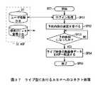
するとユーザPC2のCPU10は、自動アップロードソフトウェアに従って図37に示すルーチンRT7の開始ステップから入ってステップSP51に移る。
【0208】
ステップSP51においてユーザPC2のCPU10は、ネットワークインターフェース16からインターネット5及びISP31を介してASP32にログインし、当該ASP32のユーザ情報データベース37にアクセスしてユーザID、パスワード等を基に認証を得た後、次のステップSP52に移る。
【0209】
ステップSP52においてユーザPC2のCPU10は、ASP32の管理サーバ36によってユーザID及びパスワードを基に提供スケジュール管理データベース38に格納されているライブ型提供スケジュールコントロールファイル189(図32)の内容が確認され、次のステップSP53に移る。
【0210】
これによりASP32の管理サーバ36は、提供スケジュール管理データベース38のライブ型提供スケジュールコントロールファイル189の内容を確認することにより、ユーザPC2によって提供予定であるライブ映像のコンテンツに関する予約状況を認識するようになされている。
【0211】
ステップSP53においてユーザPC2のCPU10は、予め予約した開始時刻になると「ライブ映像のコンテンツを送信しろ」という指示命令がASP32の管理サーバ36から与えられるようになされており、当該指示命令に基づいて予め予約した開始時刻になったか否かを判定する。
【0212】
ここで否定結果が得られると、このことは管理サーバ36から指示命令が未だ与えられていないことを表しており、このときCPU10はASP32の管理サーバ36から指示命令が与えられるまで待ち受ける。
【0213】
これに対してステップSP53で肯定結果が得られると、このことはASP32の管理サーバ36から指示命令が与えられたことを表しており、このときCPU10は開始時刻になったと判断して、次のステップSP54に移る。
【0214】
ステップSP54においてユーザPC2のCPU10は、ASP32の管理サーバ36から与えられた指示命令をトリガーとして収録中であるライブ映像のコンテンツをインターネット5を介してASP32の管理サーバ36へリアルタイムに転送する転送処理を開始し、次のステップSP55で処理を終了する。
【0215】
これによりASP32の管理サーバ36は、ユーザPC2から転送されたライブ映像のコンテンツをパブリックチャンネル用に割り当てられたコンテンツサーバ39の専用の記憶領域に記録しながらストリーミング再生し、要求のあったクライアントPC4にリアルタイムで提供し得るようになされている。
【0216】
なお、このときISP31の制御サーバ33は、ユーザPC2がライブ映像のコンテンツをインターネット5を介してASP32に転送している間に発生するインターネット接続料をユーザPC2のユーザIDに対応付けて課金し、課金管理データベース34の課金データを更新する。
【0217】
またASP32の管理サーバ36は、当該ASP32のサービス利用料をユーザPC2のユーザIDに対応付けて課金し、その課金データをネットワークインターフェース41及びISP31のネットワークインターフェース35を介して課金管理データベース34に送出することにより、当該課金管理データベース34の課金データを更新するようになされている。
【0218】
因みにASP32の管理サーバ36は、ユーザPC2が「使い放題コース」と呼ばれる定額制のサービス契約をしている場合、接続開始日時から接続終了日時までの接続時間をユーザ情報データベース37のユーザ情報DBテーブル45に記録するだけでサービス利用料は一定のままで課金処理は行わない。
【0219】
(6−3)ライブ型におけるコンテンツの提供処理
ライブ型においてクライアントPC4がライブ映像のコンテンツの提供を受ける場合も、オンデマンド型においてコンテンツの提供を受ける場合と同様に、ユーザ登録が可能であり、その場合にはルーチンRT1(図8)のユーザ登録手続き処理手順に従ってユーザ登録手続きを行い、ASP32の管理サーバ36によってビューワー情報データベース40にクライアントPC4のユーザID及びパスワードに対応付けられたビューワー情報ファイルの登録が行われる。
【0220】
またクライアントPC4は、ユーザ登録を行っていない場合にはビジターとしてASP32が提供しているパーソナルキャスティングサービスのWebサイトに直接アクセスしても良く、ユーザ登録したクライアントPC4に限っては感動や共感を覚えたり、あるいは優れていると感じたコンテンツのコンテンツ制作者に対して容易に寄付を行えるようになされている。
【0221】
実際上、ASP32の管理サーバ36は、例えばユーザ登録を行ったクライアントPC4に対してライブ型でマイチャンネルを介してライブ映像のコンテンツを提供する場合、内部のハードディスクから立ち上げたコンテンツ提供プログラムに従って、図38に示すルーチンRT8の開始ステップから入ってステップSP61に移る。
【0222】
ステップSP61においてASP32の管理サーバ36は、クライアントPC4からのログイン処理を受け、当該クライアントPC4から送られてきたユーザID及びパスワードを基にビューワー情報データベース40のビューワー情報ファイルを参照し、次のステップSP62に移る。
【0223】
ステップSP62においてASP32の管理サーバ36は、ユーザID及びパスワードを基にビューワー情報データベース40のビューワー情報ファイルを参照した結果としてログインしてきたクライアントPC4が登録済の正規ユーザであるか否かを判定する。
【0224】
ここで否定結果が得られると、このことはユーザID及びパスワードがビューワー情報データベース40に登録されたものと一致しないことを表しており、このときASP32の管理サーバ36はステップSP61に戻って、クライアントPC4に対して正確なユーザID及びパスワードの入力を促してログイン処理を再実行させる。
【0225】
これに対してステップSP62で肯定結果が得られると、このことはクライアントPC4が登録済の正規ユーザであることを表しており、このときASP32の管理サーバ36は次のステップSP63に移る。
【0226】
ステップSP63においてASP32の管理サーバ36は、クライアントPC4からのアクセスに応じてパーソナルキャスティングサービスのホームページのHTMLファイルをコンテンツサーバ39から読み出し、これをネットワークインターフェース41からインターネット5を介してクライアントPC4へ転送する。
【0227】
ここでクライアントPC4は、ASP32から送られてきたパーソナルキャスティングサービスのホームページのHTMLファイルをCPUが受け取り、これをホームページ画面125(図25)として表示部に表示する。
【0228】
このホームページ画面125において、ライブモード選択表示エリア128のライブ型マイチャンネル選択ボタン130がユーザによってクリックされると、クライアントPC4のCPUは、ライブ型マイチャンネル選択ボタン130が選択されたことを示すモード選択信号をインターネット5を介してASP32の管理サーバ36に送信する。
【0229】
ステップSP64においてASP32の管理サーバ36は、クライアントPC4から送られたモード選択信号に基づいてコンテンツサーバ39からマイチャンネル用のジャンル表画面を構成するHTMLファイルを読み出し、これをネットワークインターフェース41からインターネット5を介してクライアントPC4へ送信する。
【0230】
これによりクライアントPC4のCPUは、ASP32から送られてきたマイチャンネル用のジャンル表画面のHTMLファイルを受け取り、これをマイチャンネル用のジャンル表画面135(図26)として表示部に表示する。
【0231】
このマイチャンネル用のジャンル表画面135において、カテゴリアイコン136〜144のいずれか(例えば「音楽」カテゴリアイコン139)がクライアントPC4のユーザによってクリックされると、当該クライアントPC4のCPUは「音楽」カテゴリアイコン139に対応したジャンル選択信号をインターネット5を介してASP32の管理サーバ36に送信する。
【0232】
ステップSP65においてASP32の管理サーバ36は、クライアントPC4から送られたジャンル選択信号に基づいてコンテンツサーバ39から映像カテゴリ「音楽」に関するライブ映像スケジュール表示画面を構成するHTMLファイルを読み出し、これをネットワークインターフェース41からインターネット5を介してクライアントPC4へ送信する。
【0233】
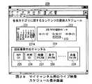
これによりクライアントPC4のCPUは、ASP32から送られてきたライブ映像スケジュール表示画面を構成するHTMLファイルを受け取り、これを図39に示すようなマイチャンネル用のライブ映像スケジュール表示画面220として表示部に表示する。
【0234】
マイチャンネル用のライブ映像スケジュール表示画面220には、日付を示すカレンダ表示エリア221と、マイチャンネルを介してライブ映像のコンテンツを提供する提供スケジュールを示すスケジュール内容表示エリア222と、現在マイチャンネルで提供中のチャンネル名を示すチャンネル種類表示エリア224とが設けられている。
【0235】
このカレンダ表示エリア221には、現在の日付(例えば2月19日)が斜線枠221Aで表示されており、クライアントPC4のユーザに対して現在の日付を容易に認識させるようになされている。
【0236】
またスケジュール内容表示エリア222には、例えば現在時刻(例えば15時10分)でASP32が提供可能なライブ映像のコンテンツの時間帯枠223(15時から16時59分59秒までの間)が表示されており、チャンネル種類表示エリア224に表示されている複数種類(10Chまで)のチャンネルボタン225〜229に対応するマイチャンネルを介してそれぞれライブ映像のコンテンツが現時点で提供可能であることを示している。
【0237】
ステップSP66においてASP32の管理サーバ36は、マイチャンネル用のライブ映像スケジュール表示画面220を見ているクライアントPC4のユーザによって例えば所望のチャンネルボタン(「木村」チャンネル)226がクリックされて選択されたか否かを判定する。
【0238】
この場合クライアントPC4のCPUは、選択されたチャンネルボタン226に対応して設定されているURLを認識し、当該URLを表すチャンネル選択信号をインターネット5を介してASP32の管理サーバ36へ送信するようになされており、これによりASP32の管理サーバ36はチャンネル選択信号を受け取った場合に所望のチャンネルボタン226がクリックされたものとして認識し得るようになされている。
【0239】
このステップSP66で否定結果が得られると、このことはライブ映像スケジュール表示画面220のチャンネル種類表示エリア224に表示されているチャンネルボタン225〜229のいずれも選択されていないことを表しており、このときASP32の管理サーバ36はチャンネルボタン225〜229のいずれかが選択されるまで待ち受ける。
【0240】
これに対してステップSP66で肯定結果が得られると、このことはチャンネルボタン225〜229のうちユーザ所望のチャンネルボタン226がクリックされて選択されたことを表しており、このときASP32の管理サーバ36は次のステップSP67に移る。
【0241】
ステップSP67においてASP32の管理サーバ36は、クリックされた時点で提供予定のライブ映像であるCM付動画像データを、コンテンツサーバ39の(「木村」チャンネルに対応する)専用の記憶領域からストリーミング再生し、これをインターネット5を介してクライアントPC4へ送信し、次のステップSP68に移って処理を終了する。
【0242】
これによりクライアントPC4のCPUは、ASP32から送られてきたコンテンツのCM付動画像データに基づいて図40に示すようなライブ映像のコンテンツ表示画面240を表示部に表示し、当該コンテンツ表示画面240の中央に設けられた動画像表示エリア241にCM映像を最初に表示した後、続いて音楽ライブの模様を表した動画像を表示する。
【0243】
ところでASP32の管理サーバ36は、ライブ映像のコンテンツをクライアントPC4へ送信するようになされているので、オンデマンド型の場合のようにコンテンツを最初から提供することはできず、クリックされた時点でライブ映像のコンテンツを途中からストリーミング再生して提供するようになされている。
【0244】
但し、この場合でもASP32の管理サーバ36は、ユーザPC2のコンテンツ制作者によってCM提供リクエストが「CM有」に設定されていた場合には、ライブ映像のコンテンツを提供する前にCM映像を必ずクライアントPC4へ送信するようになされている。
【0245】
従ってクライアントPC4では、ユーザが所望のチャンネルボタン226をクリックした場合でも、その時点から直ちにライブ映像のコンテンツを視聴できるのではなく、最初にCM映像を視聴した後からでなくてはライブ映像のコンテンツを視聴することはできない。
【0246】
このようにASP32の管理サーバ36は、ライブ映像のコンテンツをクライアントPC4へ提供する場合でも、クライアントPC4のユーザの意思に係わらず必ずCM映像を強制的に視聴させるようになされている。
【0247】
なお、このときISP31の制御サーバ33は、ユーザPC2がライブ映像のコンテンツの動画像データをインターネット5を介してASP32へ送信している間に発生するインターネット接続料をユーザPC2のユーザIDに対応付けて課金し、課金管理データベース34の課金データを更新する。
【0248】
同時にASPの管理サーバ36は、ユーザPC2からインターネット5を介して供給されるライブ映像のコンテンツの動画像データをコンテンツサーバ39を介してストリーミング再生する間に発生するサービス利用料をユーザPC2のユーザIDに対応付けて課金し、その課金データをユーザ情報データベース37のユーザ情報DBテーブル45に登録すると共に、ネットワークインターフェース41及びISP31のネットワークインターフェース35を介して課金管理データベース34に記録する。
【0249】
因みにASP32の管理サーバ36は、ユーザPC2が「使い放題コース」と呼ばれる定額制のサービス契約がなされている場合、接続開始日時から接続終了日時までの接続時間がユーザ情報データベース37のユーザ情報DBテーブル45に記録されるだけでサービス利用料は一定のままで課金処理は行わない。
【0250】
一方、ASP32の管理サーバ36は、例えばユーザ登録を行ったクライアントPC4に対してパブリックチャンネルを介してライブ映像のコンテンツを提供する場合、内部のハードディスクから立ち上げたコンテンツ提供プログラムに従って、図41に示すルーチンRT9の開始ステップから入ってステップSP71に移る。
【0251】
ステップSP71〜ステップSP73については、ルーチンRT8のステップSP61〜ステップSP63のようにマイチャンネルを介してライブ映像のコンテンツを提供する場合と同様であり、ASP32の管理サーバ36はパーソナルキャスティングサービスのホームページのHTMLファイルをネットワークインターフェース41からインターネット5を介してクライアントPC4へ転送する。
【0252】
これによりクライアントPC4は、ASP32から送られてきたパーソナルキャスティングサービスのホームページのHTMLファイルを受け取り、これをホームページ画面125(図25)として表示部17に表示する。
【0253】
このホームページ画面125において、ライブモード選択表示エリア128のライブ型パブリックチャンネル選択ボタン129がユーザによってクリックされると、クライアントPC4のCPUは、ライブ型パブリックチャンネル選択ボタン129が選択されたことを示すモード選択信号をインターネット5を介してASP32の管理サーバ36に送信する。
【0254】
ステップSP74においてASP32の管理サーバ36は、クライアントPC4から送られたモード選択信号に基づいてコンテンツサーバ39からパブリックチャンネル用のチャンネル表示画面を構成するHTMLファイルを読み出し、これをネットワークインターフェース41からインターネット5を介してクライアントPC4へ送信する。
【0255】
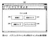
これによりクライアントPC4のCPUは、ASP32から送られてきたパブリックチャンネル用のチャンネル表示画面のHTMLファイルを受け取り、これを図42に示すようなパブリックチャンネル用のチャンネル表示画面245として表示部に表示する。
【0256】
このパブリックチャンネル用のチャンネル表画面245において、パブリックチャンネルを表す映像チャンネルアイコン246〜249のいずれか(例えば「音楽ライブ」チャンネルアイコン247)がクライアントPC4のユーザによってクリックされると、当該クライアントPC4のCPUは「音楽ライブ」チャンネルアイコン247に対応したチャンネル選択信号をインターネット5を介してASP32の管理サーバ36に送信する。
【0257】
ステップSP75においてASP32の管理サーバ36は、クライアントPC4から送られたチャンネル選択信号に基づいてコンテンツサーバ39から「音楽ライブ」チャンネルに関するパブリックチャンネル用のライブ映像スケジュール表示画面のHTMLファイルを読み出し、これをネットワークインターフェース41からインターネット5を介してクライアントPC4へ送信する。
【0258】
これによりクライアントPC4は、ASP32から送られてきたパブリックチャンネル用のライブ映像スケジュール表示画面のHTMLファイルを受け取り、これを図43に示すようなパブリックチャンネル用のライブ映像スケジュール表示画面255として表示部に表示する。
【0259】
このパブリックチャンネル用のライブ映像スケジュール表示画面255には、日付を示すカレンダ表示エリア256と、選択された「音楽ライブ」チャンネルに関するライブ映像のコンテンツの提供スケジュールを示すスケジュール内容表示エリア257とが設けられている。
【0260】
このカレンダ表示エリア256には、今日現在の日付(例えば2月19日)が斜線枠256Aで表示されており、クライアントPC4のユーザに対して現在の日付を容易に認識させるようになされている。
【0261】
またスケジュール内容表示エリア257には、ASP32が2月19日に提供予定のライブ映像のコンテンツの名称が表示されている。この場合、6時から8時59分59秒までの第1の時間帯枠257Aでは「○△×ライブ」のコンテンツを提供予定であり、10時から10時59分59秒までの第2の時間帯枠257Bでは「××ツアー」のコンテンツを提供予定であり、21時から23時59分59秒までの第3の時間帯枠257Cでは「×△コンサート」のコンテンツを提供予定であることを示している。
【0262】
またパブリックチャンネル用のライブ映像スケジュール表示画面255は、例えば現在時刻(例えば10時09分)の時点では、スケジュール内容表示エリア257の第1の時間帯枠257A及び第3の時間帯枠257Cとは異なる色で現在時刻に該当する第2の時間帯枠257Bを表示し、これによりクライアントPC4のユーザに対して現時点で「××ツアー」のコンテンツをリアルタイムに視聴し得ることを容易に認識させ得るようになされている。
【0263】
ステップSP76においてASP32の管理サーバ36は、パブリックチャンネル用のライブ映像スケジュール表示画面255を見ているクライアントPC4のユーザによって、現時点(例えば10時09分)で視聴し得る第2の時間帯枠257Bがクリックされて選択されたか否かを判定する。
【0264】
この場合クライアントPC4のCPUは、第2の時間帯枠257Bが選択された場合に、パブリックチャンネルの「音楽ライブ」チャンネルに設定されているURLを認識し、当該URLを表すチャンネル選択信号をインターネット5を介してASP32の管理サーバ36に送信するようになされており、これによりASP32の管理サーバ36はチャンネル選択信号を受け取った場合に第2の時間帯枠257Bが選択されたことを認識し得るようになされている。
【0265】
このステップSP76で否定結果が得られると、このことはスケジュール内容表示エリア257のうち現時点で視聴し得る第2の時間帯枠257Bが選択されていないことを表しており、このときASP32の管理サーバ36は第2の時間帯枠257Bが選択されるまで待ち受ける。
【0266】
これに対してステップSP76で肯定結果が得られると、このことはスケジュール内容表示エリア257における第2の時間帯枠257Bが選択されたことを表しており、このときASP32の管理サーバ36は次のステップSP77に移る。
【0267】
ステップSP77においてASP32の管理サーバ36は、クリックされた時点から「音楽ライブ」チャンネルにおいて現在提供可能なライブ映像のCM付動画像データ(「××ツアー」)を、コンテンツサーバ39の「音楽ライブ」チャンネルに対応する専用の記憶領域からストリーミング再生し、これをインターネット5を介してクライアントPC4へ送信し、次のステップSP78に移って処理を終了する。
【0268】
これによりクライアントPC4のCPUは、ASP32から送られてきたライブ映像のCM付動画像データ(「××ツアー」)に基づいて、図44に示すようなライブ映像のコンテンツ表示画面260を表示部に表示し、当該コンテンツ表示画面260の中央に設けられた動画像表示エリア261に「音楽ライブ」チャンネルで選択された第2の時間帯枠257Bに対応するライブ映像(「××ツアー」)を表示する。
【0269】
この場合もASP32の管理サーバ36は、第2の時間帯枠257Bがクリックされた時点からライブ映像のコンテンツをストリーミング再生して提供するようになされており、当該コンテンツのCM提供リクエストが「CM有」に設定されていた場合には、クリックされた時点からまず最初にCM映像をクタイアントPC4へ提供し、その後ライブ映像のコンテンツを提供するようになされている。
【0270】
このようにASP32の管理サーバ36は、クライアントPC4へパブリックチャンネルを介してライブ映像のコンテンツを提供する場合でも、クライアントPC4のユーザの意思に係わらず必ずCM映像を視聴させるようになされている。
【0271】
なお、このときISP31の制御サーバ33は、ユーザPC2がライブ映像のコンテンツの動画像データをインターネット5を介してASP32へ送信している間に発生するインターネット接続料をユーザPC2のユーザIDに対応付けて課金し、課金管理データベース34の課金データを更新する。
【0272】
同時にASPの管理サーバ36は、ユーザPC2からインターネット5を介して供給されるライブ映像のコンテンツの動画像データをコンテンツサーバ39を介してストリーミング再生する間に発生するサービス利用料をユーザPC2のユーザIDに対応付けて課金し、その課金データをユーザ情報データベース37のユーザ情報DBテーブル45に登録すると共に、ネットワークインターフェース41及びISP31のネットワークインターフェース35を介して課金管理データベース34に記録する。
【0273】
但し、この場合もASP32の管理サーバ36は、ユーザPC2が「使い放題コース」と呼ばれる定額制のサービス契約がなされている場合、接続開始日時から接続終了日時までの接続時間がユーザ情報データベース37のユーザ情報DBテーブル45に記録されるだけでサービス利用料は一定のままで課金処理は行わない。
【0274】
(7)クライアントPCによる寄付処理
ユーザ登録したクライアントPC4のユーザは、提供されたコンテンツに対して感動や共感を覚えたり、あるいはコンテンツが優れていると感じた場合に、当該コンテンツの制作者に対して容易に寄付を行うことができるようになされている。
【0275】
すなわちクライアントPC4のCPUは、ASP32からダウンロードしたコンテンツのCM付動画像ファイルに基づいて表示部に表示したオンデマンド型のコンテンツ表示画面165(図28)や、ライブ映像のコンテンツのCM付動画像データに基づいて表示部に表示したライブ型のコンテンツ表示画面240(図40)及びコンテンツ表示画面260(図44)にそれぞれ設けられている寄付ボタン167、242及び262が、コンテンツを視聴したユーザによってクリックされると、内部のハードディスク(図示せず)から立ち上げた寄付プログラムに従って、寄付ボタン167、242及び262の隣に図45に示すような寄付金額選択画面270を表示するようになされている。
【0276】
この寄付金額選択画面270には、種々の寄付金額に応じた寄付金選択ボタン271〜276が設けられており、クライアントPC4のユーザが寄付金選択ボタン271〜276の中から寄付したい金額に相当する寄付金選択ボタンを自由に選択してクリックし得るようになされている。
【0277】
従ってクライアントPC4のCPUは、例えば1000円の寄付金を寄付するために寄付金選択ボタン272がユーザによってクリックされた場合、その選択された寄付金選択ボタン272に対応する金額の寄付データを生成し、これをインターネット5を介してASP32の管理サーバ36に送信する。
【0278】
ASP32の管理サーバ36は、クライアントPC4から送られてきた寄付データを所定の換算率でポイントに換算し、コンテンツIDに対応するユーザ情報DBテーブル45をユーザ情報データベース37から検索し、そのユーザ情報DBテーブル45の累積ポイント数を寄付データに基づくポイントで更新する。
【0279】
このときクライアントPC4のCPUは、寄付データに対応する課金データを生成し、これをインターネット5を介してASP32の管理サーバ36に送信する。これによりASP32の管理サーバ36は、寄付金額に応じた課金データをクライアントPC4のASP32に対するサービス利用料と共にビューワー情報データベース40のビューワー情報ファイルに記録する。
【0280】
同時にISP31も、クライアントPC4がインターネット5を介してASP31からコンテンツの提供を受けている間に発生するインターネット接続料を課金し、その課金データをビューワー情報データベース40のビューワー情報ファイルに記録すると共に課金管理データベース34に記録する。
【0281】
ところで登録ユーザ以外のビジターがコンテンツ制作者に対して寄付を行う場合に、寄付ボタン167、242及び262がビジターによってクリックされると、クライアントPC4のCPUは当該寄付ボタン167、242及び262の隣に寄付金額選択画面270(図45)を表示すると共に、ビジターが寄付を行うためのクレジットカード番号等の入力画面(図示せず)を表示し、当該ビジターに対してクレジットカード番号の入力を促すようになされている。
【0282】
この結果クライアントPC4のCPUは、クレジットカード番号データと寄付金選択ボタンに対応する金額の寄付データとをASP32の管理サーバ36にインターネット5を介して送信し、当該管理サーバ36により寄付データに応じたポイントでユーザ情報DBテーブル45の累積ポイント数を更新するようになされている。
【0283】
なおASP32の管理サーバ36は、ビジターが行った金額の寄付データをクレジットカード番号データに基づいてクレジットカード会社の課金管理データベースに送信し、当該クレジットカード会社に対してビジターの寄付に対する課金処理を依頼する。
【0284】
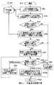
(8)月次ポイント清算処理
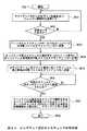
最後にコンテンツ提供システム1において、月単位で計算されるユーザ情報DBテーブル45の累積ポイント数に応じた利益還元をコンテンツ制作者に対して行うときの月次ポイント清算処理について説明するが、その前にCM映像付コンテンツがクライアントPC4に提供されるまでのCM映像付コンテンツの提供処理手順についてまとめてみると、図46に示すルーチンRT10の開始ステップから入ってステップSP81に移る。
【0285】
ステップSP81においてクライアントPC4のCPUは、チャンネル表示画面150(図27)の中から所望のチャンネルボタン155がユーザによってクリックされたことを認識し、次のステップSP82に移る。
【0286】
ステップSP82においてクライアントPC4のCPUは、選択されたチャンネルボタン155に対応するコンテンツIDをインターネット5を介してASP32の管理サーバ36へ送信し、次のステップSP83に移る。
【0287】
ステップSP83においてASP32の管理サーバ36は、内部のハードディスクから立ち上げたコンテンツ提供プログラムを起動し、例えばクライアントPC4から送られてきたコンテンツIDに基づいて提供スケジュール管理データベース38の中からオンデマンド型提供スケジュールコントロールファイル120を検索し、ユーザID及びCMリクエストの内容を確認し、次のステップSP84に移る。
【0288】
ステップSP84においてASP32の管理サーバ36は、オンデマンド型提供スケジュールコントロールファイル120を確認した結果、CMリクエストが「CM有」になっているか否かを判定する。
【0289】
ここで否定結果が得られると、このことはCMリクエストが「CM無」でクライアントPC4へ提供されるコンテンツにCM映像が付加されない設定であることを表しており、このときASP32の管理サーバ36はステップSP87に移って、CM映像の付加されていないコンテンツの動画像ファイルを提供し、次のステップSP88で処理を終了する。
【0290】
これに対してステップSP84で肯定結果が得られると、このことはCMリクエストが「CM有」でクライアントPC4へ提供されるコンテンツにCM映像が付加されるように設定されていることを表しており、このときASP32の管理サーバ36は次のステップSP85に移る。
【0291】
ステップSP85においてASP32の管理サーバ36は、CM管理データベース44に格納されているCM映像をコンテンツサーバ39に格納されている動画像ファイルの先頭部分に付加することによりCM付動画像ファイルのコンテンツを生成し、これをコンテンツサーバ39に一旦格納した後に次のステップSP86に移る。
【0292】
ステップSP86においてASP32の管理サーバ36は、CM付動画像ファイルのコンテンツをクライアントPC4へ提供したとき、発生したポイントでユーザ情報データベース37におけるユーザ情報DBテーブル45ファイルの累積ポイント数を更新し、次のステップSP87に移る。
【0293】
ステップSP87においてASP32の管理サーバ36は、CMリクエストが「CM有」であった場合にコンテンツサーバ39からCM付動画像ファイルのコンテンツを読み出し、これをインターネット5を介してクラアントPC4へ提供し、次のステップSP88に移って処理を終了する。
【0294】
このようにコンテンツ提供システム1において、ASP32の管理サーバ36は、CMリクエストが「CM有」でコンテンツサーバ39からCM付動画像ファイルのコンテンツを読み出してクライアントPC4へ提供した場合に、ポイントを発生してユーザ情報DBテーブル45の累積ポイント数を更新するようになされている。
【0295】
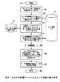
続いてコンテンツ提供システム1において、月単位で計算されるユーザ情報DBテーブル45の累積ポイント数に応じた利益還元処理をコンテンツ制作者に対して行うときの月次ポイント清算処理手順についてまとめてみると、図47に示すルーチンRT11の開始ステップから入ってステップSP91に移る。
【0296】
ステップSP91においてASP32の管理サーバ36は、内部のハードディスクから立ち上げた利益還元プログラムに基づいて、ユーザPC2のISP31のインターネット接続料や当該ASP32のサービス利用料(「使い放題コース」が設定されていた場合はサービス利用料は一定である)を加算してユーザ情報DBテーブル45を更新し終わると、次のステップSP92に移る。
【0297】
ステップSP92においてASP32の管理サーバ36は、ユーザ情報データベース37に格納されているユーザ情報DBテーブル45を参照して月単位の累積ポイント数を読み出し、次のステップSP93に移る。
【0298】
ステップSP93においてASP32の管理サーバ36は、累積ポイント数が所定ポイント数以上残っているか否かを判定する。
【0299】
ここで、否定結果が得られると、このことは累積ポイント数が所定ポイント数以上残っていないことを表しており、このときASP32の管理サーバ36は次のステップSP94に移る。
【0300】
ステップSP94においてASP32の管理サーバ36は、月単位の累積ポイント数が所定ポイント数以上残っていないので、累積ポイント数に応じた利益還元処理を行わずに現時点でのサービス利用料の請求処理をユーザPC2に対して行い、次のステップSP101に移って処理を終了する。
【0301】
これに対してステップSP93で肯定結果が得られると、このことは月単位の累積ポイント数が所定ポイント数以上残っていることを表しており、このときASP32の管理サーバ36は累積ポイント数に応じた利益還元処理を行うために次のステップSP95に移る。
【0302】
ステップSP95においてASP32の管理サーバ36は、ユーザ情報DBテーブル45における累積ポイント数の相当額を当該ASP32のサービス利用料から減算し、その減算処理したサービス利用料分のポイント数をユーザ情報DBテーブル45の累積ポイント数から減算して更新し、次のステップSP96に移る。
【0303】
これによりユーザPC2のコンテンツ制作者は、ASP32からクレジットカード会社を通じて受ける支払い請求のサービス利用料が減額もしくは相殺され、累積ポイントに応じた利益還元処理を受けたことになる。
【0304】
ステップSP96においてASP32の管理サーバ36は、当該ASP32のサービス利用料を利益還元した後の累積ポイント数が所定ポイント数以上残っているか否かを判定する。
【0305】
ここで、否定結果が得られると、このことは累積ポイント数が所定ポイント数以上残っていないことを表しており、このときASP32の管理サーバ36は次のステップSP94に移ってサービス利用料の請求処理を行い、次のステップSP101で処理を終了する。
【0306】
これに対してステップSP96で肯定結果が得られると、このことは累積ポイント数が所定ポイント数以上残っていることを表しており、このときASP32の管理サーバ36は次のステップSP97に移る。
【0307】
ステップSP97においてASP32の管理サーバ36は、ISP31に対して累積ポイント数の相当額をユーザPC2のインターネット接続料から減算処理し、その減算処理したインターネット接続料分のポイント数をユーザ情報DBテーブル45の累積ポイント数から減算して更新した後、次のステップSP98に移る。
【0308】
これによりユーザPC2のコンテンツ制作者は、ISP31からクレジットカード会社を通じて受ける支払い請求のインターネット接続料が減額もしくは相殺され、ASP32のサービス利用料に続いて累積ポイント数に応じた利益還元処理を受けたことになる。
【0309】
ステップSP98においてASP32の管理サーバ36は、この段階で未だ累積ポイント数が残っているか否かを判定する。ここで、累積ポイント数が100万ポイント以上残っていた場合、ASP32の管理サーバ36は次のステップSP99に移る。
【0310】
ステップSP99においてASP32の管理サーバ36は、累積ポイント数の100万ポイント超過分をクレジットカード会社を通じて例えば決済データから減算して決済処理するように当該クレジットカード会社に指示した後、100万ポイント超過分のポイント数をユーザ情報DBテーブル45の累積ポイント数から減算して累積ポイント数を新たに更新し、再度ステップSP98に戻る。
【0311】
これに対してステップSP98で累積ポイント数が100万ポイント以下で10万ポイント以上残っていた場合、ASP32の管理サーバ36は次のステップSP100に移る。
【0312】
ステップSP100においてASP32の管理サーバ36は、オンライン通信販売会社6にインターネット5を介して累積ポイント数の10万ポイント超過分のポイントデータを転送した後、ユーザ情報DBテーブル45の累積ポイント数から10万ポイント超過分のポイント数を減算して累積ポイント数を新たに更新し、次のステップSP101で処理を終了する。
【0313】
この場合オンライン通信販売会社6は、ユーザ登録時にASP32から転送されたユーザ情報DBテーブル45の内容に基づいてコンテンツ制作者の住所や電子メールアドレス等の個人情報を認識しており、10万ポイント超過分のポイント数に応じた所定の商品をユーザPC2のコンテンツ制作者に対して宅配することにより、利益還元処理を行うようになされている。
【0314】
さらにステップSP98で累積ポイント数が10万ポイント以上残っていなかった場合、ASP32の管理サーバ36はステップSP94に移って、サービス利用料の請求処理を行い、次のステップSP101で処理を終了する。
【0315】
(9)本実施の形態における動作及び効果
以上の構成において、ユーザPC2はコンテンツのスケジュール予約を行うとき、CM映像が付加されたCM付動画像ファイルのコンテンツをクライアントPC4へ提供するか否かの選択を例えばCM提供リクエスト画面115(図18)で行うことにより、オンデマンド型提供スケジュールコントロールファイル120を生成し、これをASP32の管理サーバ36に送信する。
【0316】
ASP32の管理サーバ36は、オンデマンド型提供スケジュールコントロールファイル120を受信し、これを提供スケジュール管理データベース38に格納する。
【0317】
そしてASP32の管理サーバ36は、オンデマンド型提供スケジュールコントロールファイル120の内容としてCMリクエストが「CM有」に設定されていた場合、CMクライアント7から予め供給されてCM管理データベース44に格納しておいたCM映像をコンテンツの動画像ファイルの先頭部分に付加することによりCM付動画像ファイルを生成し、これをコンテンツサーバ39に格納しておく。
【0318】
この状態でASP32の管理サーバ36は、クライアントPC4からコンテンツの要求を受けると、オンデマンド型提供スケジュールコントロールファイル120に従ってコンテンツサーバ39からCM付動画像ファイルのコンテンツを読み出し、これをインターネット5を介してクライアントPC4へ送信する。
【0319】
これによりクライアントPC4は、CM付動画像ファイルに基づいてコンテンツ表示画面165(図28)に最初CM映像を表示した後、続いてコンテンツの動画像を表示することになり、ユーザは所望のコンテンツを選択するときにCMを意識することがないにも係わらず最初にCM映像を視聴することになる。
【0320】
このようにコンテンツ提供システム1としては、クライアントPC4のユーザにCMのことを意識させるとなくコンテンツを選択させるだけで、必ずコンテンツの前にCM映像を視聴させることができるので、当該CM映像の宣伝効果に応じた恩恵をCMクライアント7側が受け、当該CMクライアント7側から宣伝効果に応じた報酬をASP32側が受けた後、CM映像が付加されたコンテンツのコンテンツ制作者に対して正当な利益還元を行い得るビジネスモデルを構築することが可能となる。
【0321】
以上の構成によれば、コンテンツ提供システム1におけるASP32の管理サーバ36は、CM映像をコンテンツの動画像ファイルの先頭部分に付加することにより生成したCM映像付動画像ファイルをコンテンツサーバ39に格納しておき、クライアントPC4からコンテンツの要求を受けたとき、オンデマンド型提供スケジュールコントロールファイル120に従ってCM映像付動画像ファイルのコンテンツを提供することにより、クライアントPC4のユーザにコンテンツを選択させるだけで必ずCM映像を視聴させることができる。
【0322】
(10)他の実施の形態
なお上述の実施の形態においては、広告情報としてCM映像をコンテンツに付加するようにした場合について述べたが、本発明はこれに限らず、CM音声を付加するようにしても良い。この場合にも、上述の実施の形態と同様の効果を得ることができる。
【0323】
また上述の実施の形態においては、CM映像をコンテンツの動画像ファイルの先頭部分に付加することにより生成したCM映像付動画像ファイルをコンテンツ蓄積提供手段としてのコンテンツサーバ39に格納しておき、記憶手段としての提供スケジュール管理データベース38に格納されたコンテンツ提供条件データとしてのオンデマンド型提供スケジュールコントロールファイル120に従って、制御手段としての管理サーバ36の制御の基にCM映像付動画像ファイルをコンテンツサーバ39から提供するようにした場合について述べたが、本発明はこれに限らず、CM映像をコンテンツの動画像ファイルの終了部分に付加することにより生成したCM映像付動画像ファイルを提供するようにしても良い。
【0324】
さらに上述の実施の形態においては、コンテンツとして動画像ファイル又はCM付動画像ファイルのいずれかをオンデマンド型提供スケジュールコントロールファイル120に従ってコンテンツサーバ39から提供するためのコンテンツ提供プログラムが予め管理サーバ36のハードディスクにインストールされている場合について述べたが、本発明はこれに限らず、コンテンツ提供プログラムの格納された例えばCD−ROM(Compact Disc-Read Only Memory) 、DVD(Digital Video Disc)等のパッケージメディアでなるプログラム格納媒体を再生することによりコンテンツ提供プログラムをインストールしても良く、またコンテンツ提供プログラムが一時的もしくは永続的に格納される半導体メモリや光磁気ディスク等のプログラム格納媒体を再生することによりコンテンツ提供プログラムをインストールしても良い。
【0325】
これらのプログラム格納媒体にコンテンツ提供プログラムを格納する手段としてはローカルエリアネットワーク、ディジタル衛星放送等の有線及び無線通信媒体を利用しても良く、ルータやモデム等の各種通信インターフェースを介在させて格納するようにしても良い。
【0326】
さらに上述の実施の形態においては、ASP32の管理サーバ36がコンテンツを提供する対象としてクライアントPC4を用いるようにした場合について述べたが、本発明はこれに限らず、インターネット5を介して接続されるものであれば携帯情報端末や携帯電話機からの要求に応じてコンテンツを提供するようにしても良い。
【0327】
さらに上述の実施の形態においては、ネットワークとしてインターネット5を用いるようにした場合について述べたが、本発明はこれに限らず、有線又は無線で構築された他の種々のネットワークを用いても良い。
【0328】
【発明の効果】
上述のように本発明によれば、寄付データを所定の換算率でポイントに換算し、コンテンツ蓄積提供手段が広告付コンテンツをクライアントへ提供した提供回数に応じて発生した累積ポイント数を当該寄付データに基づいて換算したポイントにより更新し、当該更新した累積ポイント数を用いて課金処理を実行することができるので、寄付データを累積ポイント数に反映した利益還元を実行し得る利益還元装置、利益還元方法及びシステムを実現することができる。
【図面の簡単な説明】
【図1】インターネットを利用した電子商取引の原理の説明に供する略線図である。
【図2】本発明によるコンテンツ提供システムの構成を示す略線的ブロツク図である。
【図3】ユーザPCの構成を示す略線的ブロック図である。
【図4】デスクトップ画面を示す略線図である。
【図5】ユーザ情報登録画面を示す略線図である。
【図6】ユーザ情報ファイルを示す略線図である。
【図7】コンテンツ提供プロバイダの構成を示す略線的ブロック図である。
【図8】ASPの管理サーバによるユーザ登録手続き処理手順を示すフローチャートである。
【図9】ユーザ情報DBに登録されたユーザ情報DBテーブルの内容を示す略線図である。
【図10】キャプチャー画面を示す略線図である。
【図11】確認画面を示す略線図である。
【図12】編集画面を示す略線図である。
【図13】オンデマンド型パーソナルキャスティング制御画面を示す略線図である。
【図14】プルダウンメニューを示す略線図である。
【図15】マイチャンネルジャンル表画面を示す略線図である。
【図16】コーデック選択画面を示す略線図である。
【図17】オンデマンド型提供スケジュール管理画面を示す略線図である。
【図18】CM提供リクエスト画面を示す略線図である。
【図19】CMリンク設定画面を示す略線図である。
【図20】コンテンツID設定画面を示す略線図である。
【図21】オンデマンド型提供スケジュールコントロールファイルの内容を示す略線図である。
【図22】オンデマンド型におけるASPへのコネクト処理手順を示すフローチャートである。
【図23】提供スケジュールの確認及び変更処理手順を示すフローチャートである。
【図24】オンデマンド型のキャスティング処理手順を示すフローチャートである。
【図25】パーソナルキャスティングサービスのホームページ画面を示す略線図である。
【図26】マイチャンネル用のジャンル表画面を示す略線図である。
【図27】映像ジャンル「車」に関するチャンネル表示画面を示す略線図である。
【図28】選択されたチャンネルボタンに対応するコンテンツが表示されたコンテンツ表示画面を示す略線図である。
【図29】ライブ型パーソナルキャスト制御画面を示す略線図である。
【図30】ライブ型提供スケジュール管理画面の表示処理手順を示すフローチャートである。
【図31】パブリックチャンネル用のライブ型提供スケジュール管理画面を示す略線図である。
【図32】ライブ型提供スケジュールコントロールファイルの内容を示す略線図である。
【図33】予約処理手順を示すフローチャートである。
【図34】マイチャンネル用のライブ型提供スケジュール管理画面を示す略線図である。
【図35】マイチャンネル用のライブ型提供スケジュールコントロールファイルの内容を示す略線図である。
【図36】予約不能メッセージ表示画面を示す略線図である。
【図37】ライブ型におけるASPへのコネクト処理手順を示すフローチャートである。
【図38】ライブ型でマイチャンネルを介して行うキャスティング処理手順を示すフローチャートである。
【図39】マイチャンネル用のライブ映像スケジュール表示画面を示す略線図である。
【図40】選択されたチャンネルボタンに対応するライブ映像のコンテンツが表示されたコンテンツ表示画面を示す略線図である。
【図41】ライブ型でパブリックチャンネルを介して行うキャスティング処理手順を示すフローチャートである。
【図42】パブリックチャンネル用のチャンネル表示画面を示す略線図である。
【図43】パブリックチャンネル用のライブ映像スケジュール表示画面を示す略線図である。
【図44】音楽ライブチャンネルで選択されたライブ映像のコンテンツが表示されたコンテンツ表示画面を示す略線図である。
【図45】寄付金額選択画面を示す略線図である。
【図46】CM映像付コンテンツの提供処理手順を示すフローチャートである。
【図47】利益還元処理手順を示すフローチャートである。
【符号の説明】
1……コンテンツ提供サービスシステム、2……ユーザPC、3……コンテンツ提供プロバイダ、4……クライアントPC、5……インターネット、6……オンライン通信販売会社、7……CMクライアント、10……CPU、11……バス、12……HDD、14……IEEE1394インターフェース、16、35、41……ネットワークインターフェース、17……表示部、31……ISP、32……ASP、33……制御サーバ、34……課金管理データベース、36……管理サーバ、37……ユーザ情報DB、38……提供スケジュール管理DB、39……コンテンツサーバ、40……ビューワー情報DB、44……CM管理DB、45……ユーザ情報DBテーブル。[0001]
BACKGROUND OF THE INVENTION
The present invention relates to a content providing apparatus, a content providing method, a program storage medium, and a content providing system, and is suitable for application to, for example, a computer network system that provides content via the Internet.
[0002]
[Prior art]
2. Description of the Related Art Conventionally, in a computer network system, for example, when providing content including video and / or audio created by an individual via the Internet, a user generally opens a personal home page created using a personal computer. It has been broken.
[0003]
When opening a personal homepage in this way, the user obtains a homepage creation program via a personal computer, creates a homepage hyperlinked with a plurality of contents based on the homepage creation program, and creates it as an Internet service provider ( This is hereinafter stored in a server).
[0004]
The ISP provides a home page from the server to clients that have accessed via the Internet, and when an anchor on the home page is clicked, the hyperlinked content is subsequently provided.
[0005]
A banner advertisement is displayed on the home page, and when the client user clicks the banner advertisement, the ISP transmits the detailed contents of the banner advertisement to the client for viewing.
[0006]
[Problems to be solved by the invention]
By the way, in the computer network system having such a configuration, in order to allow the user to view the banner advertisement on the home page provided to the client, the banner advertisement needs to be clicked. There is a problem that the user cannot be clicked and the detailed contents of the banner advertisement cannot always be viewed by the user.
[0007]
In addition, it is not easy to create a homepage with a banner advertisement via a personal computer, and that alone has a problem of complicating the homepage creator.
[0008]
The present invention has been made in consideration of the above points, and intends to propose a content providing apparatus, a content providing method, a program storage medium, and a content providing system capable of easily and reliably providing advertisement information to a client user. It is.
[0009]
[Means for Solving the Problems]
In order to solve such a problem, in the present invention, content with advertisement information generated by adding the advertisement information supplied from the advertisement requester to the content supplied from the content supply means is stored by the content storage providing means, In response to a request from the client, content with advertisement information is provided to the client via the network by means of content accumulation and provision,The client Content with advertising informationBy playing the content with advertisement information after receiving Display section of the clientContent display screen displayAnd the concerned Donation button provided on the content display screenBut operationWhen a donation amount display screen showing multiple types of amounts is displayed, it is selected from the donation amount display screen. Generate based on amountShi Received donation data from the client via the receiving means,Donation data generated based on the amount selected pointConverted to Depending on the number of times content accumulation and provision means provided content with advertisements to clientsOccurred Cumulative pointsUpdate with converted points and execute billing process using the updated accumulated points To do.
[0010]
ThisDonation data at a predetermined conversion rate pointIn terms of content storage and provision means Number of times content with advertisements was provided to clientsOccurred according to Cumulative pointsIs updated with points converted based on the donation data, and billing is executed using the updated accumulated points So you canProfit return reflecting donation data in accumulated points can do.
[0011]
DETAILED DESCRIPTION OF THE INVENTION
Hereinafter, an embodiment of the present invention will be described in detail with reference to the drawings.
[0012]
(1) Principle of electronic commerce using the Internet
The Internet is a computer network constructed by connecting a large number of computers to each other via a communication link, and uses various services such as e-mail, Gopher, and WWW (World Wide Web) between computers. Information can be sent and received.
[0013]
That is, as shown in FIG. 1, a WWW server 301 (also called a Web server or a Web site) that provides various services such as WWW to client PCs (Personal Computers) 302-1 to 302-N via the Internet 300 ) Stores a Web page composed of graphics information such as graphics and images in an internal hard disk.
[0014]
Each resource used on the WWW such as the
[0015]
Accordingly, the client PCs 302-1 to 302-N connected to the Internet 300, for example, when the URL of a Web page desired to be browsed is specified by a user using a predetermined transfer protocol such as HTTP (Hyper Text Transfer Protocol), According to the URL, a web page browsing request is made to the
[0016]
When the client PC 302-1 to 302-N receives a Web page transmitted from the
[0017]
Here, the Web page is typically defined using HTML (Hyper Text Markup Language), and how the Web page is displayed on the HTML document defining the Web page. In order to designate these, symbols called tags (reserved words) defined by HTML are included.
[0018]
The HTML document contains various tags for displaying graphics, controls, and other functions, and the URL of the Web page that can be used on the
[0019]
Therefore, the Web page is displayed on the display unit of the client PCs 302-1 to 302-N by a display method intended by the provider of the Web page.
[0020]
Recently, the above-mentioned WWW is used for electronic commerce using the Internet 300.
[0021]
In this case, the
[0022]
As a result, the client PCs 302-1 to 302-N display the Web page received from the
[0023]
The client PCs 302-1 to 302-N notify the
[0024]
Upon receiving the request, the
[0025]
Next, when receiving the above customer information, the
[0026]
In such electronic commerce using the
[0027]
By the way, there are things called XML (eXtensible Markup Language) in addition to HTML, which defines Web pages. Although XML uses tags in the same way as HTML, it can express the structure and meaning of a document. In addition, attributes such as a hierarchical structure and a data type can be specified for a tag by a document type definition (DTD).
[0028]
Therefore, in the
[0029]
(2) Configuration of content provision system
In FIG. 2,
[0030]
The
[0031]
Here, the
[0032]
(3) User registration procedure for user PC
In this
[0033]
As shown in FIG. 3, the
[0034]
In such a
[0035]
That is, when the
[0036]
This user
[0037]
Here, the personal casting service is a content provision form newly started in the
[0038]
On the user
[0039]
Therefore, when the
[0040]
As shown in FIG. 7, the
[0041]
The
[0042]
The
[0043]
The
[0044]
Upon receiving the
[0045]
In step SP1, the
[0046]
When the credit card number is not the correct number of digits, the
[0047]
In step SP2, the
[0048]
In step SP3, the
[0049]
In step SP4, the
[0050]
In step SP5, the
[0051]
Here, in the user information DB table 45 newly registered in the
[0052]
As described above, the
[0053]
The
[0054]
Incidentally, the user status is a rating for the content creator according to the accumulated number of points, and is ranked as
[0055]
In step SP6, the
[0056]
At this time, the
[0057]
As a result, the
[0058]
When the upload
[0059]
As a result, the
[0060]
As described above, when the user ID is selected and the URL is determined by the registration procedure of the user information by the content creator and the automatic upload software is downloaded from the
[0061]
As a result, in the
[0062]
In step SP7, since the
[0063]
By the way, the
[0064]
As a result, the control server 33 of the
[0065]
Therefore, each time the
[0066]
Incidentally, the
[0067]
(4) Form of personal casting service
In the
[0068]
In the on-demand type, content is stored in advance in a dedicated storage area of the
[0069]
On the other hand, in the live type, only a registered user of an unspecified number of personal casting services has a
[0070]
In this way, in the live type, an unspecified number of registered users can freely provide content by reserving a use time slot for a dedicated storage area of the
[0071]
(5) On-demand personal casting service
Next, the on-demand personal casting service of the
[0072]
(5-1) On-demand content production processing
The
[0073]
In this case, the
[0074]
Then, the
[0075]
At this time, the
[0076]
Next, the
[0077]
Accordingly, after the content creator confirms and edits the scene of the recorded moving image data on the
[0078]
The
[0079]
Therefore, the
[0080]
(5-2) On-demand schedule reservation
Thereafter, when the content creator clicks the
[0081]
On the on-demand type personal
[0082]
The on-demand type personal
[0083]
The pull-
[0084]
When the
[0085]
The my channel
[0086]
When the
[0087]
In this
[0088]
Further, when the schedule creator button 85C in the pull-
[0089]
On the on-demand type provision
[0090]
In the calendar display area 106 of the on-demand type provision
[0091]
Then, in the schedule content display area 108 of the on-demand type provision
[0092]
That is, the time
[0093]
Subsequently, when the content creator clicks, a desired time frame in the time
[0094]
When the
[0095]
That is, when the provision schedule program receives a request from the
[0096]
Further, when the content creator clicks the CM
[0097]
On this CM
[0098]
Further, when the content creator clicks the CM
[0099]
This CM
[0100]
Further, when the content creator clicks the content ID setting button 85F in the pull-
[0101]
The content
[0102]
As described above, the
[0103]
That is, in the on-demand provision schedule control file 120 once stored in the
[0104]
Accordingly, the
[0105]
Although the CM link setting and the content ID setting are described as being set by the
[0106]
For example, the CM link setting is automatically performed when the
[0107]
Further, for example, when an image is uploaded, a content ID is automatically set on the
[0108]
(5-3) Connect processing to ASP in on-demand type
Next, when the content creator confirms the content of the on-demand personal cast control screen 75 (FIG. 13) and the
[0109]
In step SP11, the
[0110]
In step SP12, since the
[0111]
In this manner, the
[0112]
The
[0113]
Note that the
[0114]
By the way, the control server 33 of the
[0115]
The
[0116]
Incidentally, the
[0117]
By the way, after the upload of the on-demand type provision
[0118]
At this time, the
[0119]
In step SP15, when the content creator clicks the schedule
[0120]
In step SP16, the
[0121]
As described above, the
[0122]
Thereafter, when the content creator attempts to change the contents of the on-demand type provision
[0123]
In step SP17, the
[0124]
In step SP18, when the
[0125]
As a result, the
[0126]
(5-4) On-demand content provision processing
The
[0127]
Further, the
[0128]
In practice, the
[0129]
In step SP21, the
[0130]
In step SP22, the
[0131]
If a negative result is obtained here, this means that the user ID and password do not match those registered in the viewer information database 40. At this time, the
[0132]
On the other hand, if an affirmative result is obtained in step SP22, this indicates that the
[0133]
In step SP23, the
[0134]
Here, the
[0135]
On this
[0136]
When the on-demand type my channel selection button 127 is clicked on the
[0137]
In
[0138]
As a result, the CPU of the
[0139]
This
[0140]
When one of the
[0141]
In step SP25, the
[0142]
As a result, the CPU of the
[0143]
On this
[0144]
In step SP26, the
[0145]
In this case, the CPU of the
[0146]
Therefore, the
[0147]
If a negative result is obtained in this step SP26, this means that none of the
[0148]
On the other hand, if a positive result is obtained in step SP26, this indicates that the user desired
[0149]
In step SP27, when the
[0150]
In practice, when the channel button (for example, Kimura Ch) 155 is clicked on the
[0151]
As a result, the
[0152]
As described above, the
[0153]
As a result, even when the
[0154]
At this time, the
[0155]
In this case, since the counted number of accesses corresponds to the number of viewers of the CM video, the
[0156]
(6) Live-type personal casting service
Next, the live-type personal casting service of the
[0157]
(6-1) Live schedule reservation
In the live type, in order to provide live video content in real time, a moving image file of the content is created as in the on-demand type, and the created moving image file of the content is stored in the
[0158]
However, in the live type, content is provided via a shared public channel (wedding channel, music live channel, theater live channel or event live channel), so there is a time slot for using the public channel in advance. It is necessary to make a reservation.
[0159]
In other words, reserving a time slot that uses a public channel means reserving a time slot that uses a dedicated storage area of the
[0160]
When the
[0161]
That is, the
[0162]
Then, the
[0163]
On the live-type personal
[0164]
On the live personal
[0165]
Further, on the live-type personal
[0166]
In such a live type personal
[0167]
In step SP31, the
[0168]
In step SP32, the
[0169]
In step SP33, the
[0170]
This live-type provision
[0171]
When, for example, the music live Ch button 177 is clicked by the content creator among these four types of public channels, the
[0172]
At this time, in the schedule time schedule table 182 of the schedule
[0173]
The content creator confirms the reservation status on the desired reservation date (February 19) displayed in the
[0174]
As a result, the
[0175]
Further, when the content creator inputs the name of the content to be provided in the
[0176]
Subsequently, if the
[0177]
Further, the
[0178]
As described above, the
[0179]
In the live-type provision
[0180]
When the
[0181]
In step SP41, the
[0182]
In step SP42, since the
[0183]
As a result, the
[0184]
At this time, the
[0185]
In step SP43, the
[0186]
However, the live-type provision
[0187]
By the way, as a result of confirming the reservation status displayed in the schedule
[0188]
When the content creator clicks the My Channel button 188 provided at the bottom of the live-type provision
[0189]
The live-type provision
[0190]
Also in this case, when the reservation date (for example, February 19) in the
[0191]
Therefore, the content creator confirms the reservation status displayed in the
[0192]
Thereby, the
[0193]
Next, when the category (music) icon 199 corresponding to the video genre of the live video is clicked from among the
[0194]
At this time, the
[0195]
Subsequently, if the
[0196]
In addition, the
[0197]
As described above, when the
[0198]
By the way, when a plurality of content creators make a reservation for providing live video content via My Channel, the
[0199]
Therefore, when the
[0200]
The
[0201]
As a result, the
[0202]
As described above, the
[0203]
Therefore, when the content creator of user PC2 provides live video of his amateur band in real time, he chooses the method of providing via my channel and provides live video of prominent professional artists in real time. It is possible to select a method of providing via a public channel.
[0204]
As described above, in the content providing
[0205]
(6-2) Connect processing to ASP in live type
Next, the
[0206]
At this time, the content creator recognizes the reservation content when providing the live video content by checking the live-type personal
[0207]
Then, the
[0208]
In step SP51, the
[0209]
In step SP52, the
[0210]
Thereby, the
[0211]
At step SP53, the
[0212]
If a negative result is obtained here, this means that an instruction command has not yet been given from the
[0213]
On the other hand, if a positive result is obtained in step SP53, this indicates that an instruction command has been given from the
[0214]
In step SP54, the
[0215]
As a result, the
[0216]
At this time, the control server 33 of the
[0217]
The
[0218]
Incidentally, the
[0219]
(6-3) Live content provision processing
When the
[0220]
Further, the
[0221]
In practice, the
[0222]
In step SP61, the
[0223]
In step SP62, the
[0224]
If a negative result is obtained here, this means that the user ID and password do not match those registered in the viewer information database 40. At this time, the
[0225]
On the other hand, if a positive result is obtained in step SP62, this indicates that the
[0226]
In step SP63, the
[0227]
Here, in the
[0228]
When the user clicks the live-type my channel selection button 130 in the live mode
[0229]
In step SP 64, the
[0230]
As a result, the CPU of the
[0231]
When one of the
[0232]
In step SP65, the
[0233]
As a result, the CPU of the
[0234]
On the live video
[0235]
In the
[0236]
In the schedule
[0237]
In step SP66, the
[0238]
In this case, the CPU of the
[0239]
If a negative result is obtained in step SP66, this indicates that none of the
[0240]
On the other hand, if a positive result is obtained in step SP66, this indicates that the user desired
[0241]
In step SP67, the
[0242]
As a result, the CPU of the
[0243]
By the way, since the
[0244]
However, even in this case, the
[0245]
Therefore, in the
[0246]
Thus, even when the
[0247]
At this time, the control server 33 of the
[0248]
At the same time, the
[0249]
Incidentally, the
[0250]
On the other hand, when the
[0251]
Step SP71 to step SP73 are the same as the case of providing live video content via My Channel as in step SP61 to step SP63 of routine RT8, and the
[0252]
As a result, the
[0253]
When the user clicks the live type public channel selection button 129 in the live mode
[0254]
In step SP74, the
[0255]
As a result, the CPU of the
[0256]
When one of the
[0257]
In step SP75, the
[0258]
As a result, the
[0259]
The live video
[0260]
In this
[0261]
In the schedule
[0262]
Further, the live video
[0263]
In step SP76, the
[0264]
In this case, when the
[0265]
If a negative result is obtained in this step SP76, this means that the
[0266]
On the other hand, if a positive result is obtained in step SP76, this indicates that the
[0267]
In step SP77, the
[0268]
As a result, the CPU of the
[0269]
In this case as well, the
[0270]
As described above, even when the
[0271]
At this time, the control server 33 of the
[0272]
At the same time, the
[0273]
In this case, however, the
[0274]
(7) Donation processing by client PC
When the registered user of the
[0275]
That is, the CPU of the
[0276]
The donation
[0277]
Therefore, the CPU of the
[0278]
The
[0279]
At this time, the CPU of the
[0280]
At the same time, the
[0281]
By the way, when a visitor other than the registered user makes a donation to the content creator, if the donation buttons 167, 242 and 262 are clicked by the visitor, the CPU of the
[0282]
As a result, the CPU of the
[0283]
The
[0284]
(8) Monthly point settlement process
Lastly, in the
[0285]
In step SP81, the CPU of the
[0286]
In step SP82, the CPU of the
[0287]
In step SP83, the
[0288]
In step SP84, the
[0289]
If a negative result is obtained here, this means that the CM request is “no CM” and the CM video is not added to the content provided to the
[0290]
On the other hand, if a positive result is obtained in step SP84, this means that the CM request is “CM present” and the CM video is set to be added to the content provided to the
[0291]
In step SP85, the
[0292]
In step SP86, when the
[0293]
In step SP87, when the CM request is “CM present”, the
[0294]
As described above, in the
[0295]
Next, in the
[0296]
In step SP91, the
[0297]
In step SP92, the
[0298]
In step SP93, the
[0299]
Here, if a negative result is obtained, this means that the accumulated number of points does not remain more than the predetermined number of points. At this time, the
[0300]
In step SP94, the
[0301]
On the other hand, if an affirmative result is obtained in step SP93, this indicates that the cumulative number of points per month remains more than the predetermined number of points, and at this time, the
[0302]
In step SP95, the
[0303]
As a result, the content creator of the
[0304]
In step SP96, the
[0305]
Here, if a negative result is obtained, this means that the accumulated point number does not remain beyond the predetermined point number. At this time, the
[0306]
On the other hand, if an affirmative result is obtained in step SP96, this indicates that the accumulated number of points remains more than the predetermined number of points. At this time, the
[0307]
In step SP97, the
[0308]
As a result, the content creator of the
[0309]
In step SP98, the
[0310]
In step SP99, the
[0311]
On the other hand, when the cumulative point number is 1 million points or less and 100,000 points or more remain in step SP98, the
[0312]
In step SP100, the
[0313]
In this case, the online
[0314]
Furthermore, if the accumulated point number does not remain 100,000 or more in step SP98, the
[0315]
(9) Operations and effects in the present embodiment
In the above configuration, when the
[0316]
The
[0317]
Then, when the CM request is set to “CM present” as the content of the on-demand provision
[0318]
In this state, when the
[0319]
As a result, the
[0320]
As described above, the
[0321]
According to the above configuration, the
[0322]
(10) Other embodiments
In the above-described embodiment, the case where the CM video is added to the content as the advertisement information has been described. However, the present invention is not limited to this, and CM audio may be added. Also in this case, the same effect as the above-described embodiment can be obtained.
[0323]
In the above-described embodiment, the CM video-attached moving image file generated by adding the CM video to the beginning of the content moving image file is stored in the
[0324]
Furthermore, in the above-described embodiment, a content providing program for providing either a moving image file or a CM-attached moving image file as content from the
[0325]
As means for storing the content providing program in these program storage media, wired and wireless communication media such as a local area network and digital satellite broadcasting may be used, and stored via various communication interfaces such as routers and modems. You may do it.
[0326]
Furthermore, in the above-described embodiment, the case where the
[0327]
Furthermore, in the above-described embodiment, the case where the
[0328]
【The invention's effect】
As described above, according to the present invention,Donation data at a predetermined conversion rate pointIn terms of content storage and provision means Number of times content with advertisements was provided to clientsOccurred according to Cumulative pointsIs updated with points converted based on the donation data, and billing is executed using the updated accumulated points So you canProfit return reflecting donation data in accumulated points A profit return device, a profit return method, and a system that can be realized can be realized.
[Brief description of the drawings]
FIG. 1 is a schematic diagram for explaining the principle of electronic commerce using the Internet.
FIG. 2 is a schematic block diagram showing a configuration of a content providing system according to the present invention.
FIG. 3 is a schematic block diagram showing a configuration of a user PC.
FIG. 4 is a schematic diagram showing a desktop screen.
FIG. 5 is a schematic diagram showing a user information registration screen.
FIG. 6 is a schematic diagram showing a user information file.
FIG. 7 is a schematic block diagram showing a configuration of a content providing provider.
FIG. 8 is a flowchart showing a user registration procedure processing procedure performed by an ASP management server.
FIG. 9 is a schematic diagram illustrating contents of a user information DB table registered in the user information DB.
FIG. 10 is a schematic diagram illustrating a capture screen.
FIG. 11 is a schematic diagram showing a confirmation screen.
FIG. 12 is a schematic diagram illustrating an editing screen.
FIG. 13 is a schematic diagram showing an on-demand type personal casting control screen.
FIG. 14 is a schematic diagram showing a pull-down menu.
FIG. 15 is a schematic diagram showing a My Channel genre table screen;
FIG. 16 is a schematic diagram illustrating a codec selection screen.
FIG. 17 is a schematic diagram illustrating an on-demand type provision schedule management screen.
FIG. 18 is a schematic diagram showing a CM provision request screen.
FIG. 19 is a schematic diagram illustrating a CM link setting screen.
FIG. 20 is a schematic diagram illustrating a content ID setting screen.
FIG. 21 is a schematic diagram showing the contents of an on-demand type provision schedule control file.
FIG. 22 is a flowchart showing a connection processing procedure to an ASP in an on-demand type.
FIG. 23 is a flowchart showing a procedure for confirming and changing a provision schedule.
FIG. 24 is a flowchart showing an on-demand type casting process procedure;
FIG. 25 is a schematic diagram illustrating a home page screen of a personal casting service.
FIG. 26 is a schematic diagram showing a genre table screen for My Channel.
FIG. 27 is a schematic diagram illustrating a channel display screen related to a video genre “car”.
FIG. 28 is a schematic diagram illustrating a content display screen on which content corresponding to a selected channel button is displayed.
FIG. 29 is a schematic diagram illustrating a live-type personal cast control screen.
FIG. 30 is a flowchart showing a display processing procedure for a live-type provision schedule management screen.
FIG. 31 is a schematic diagram illustrating a live-type provision schedule management screen for public channels.
FIG. 32 is a schematic diagram showing the contents of a live-type provision schedule control file.
FIG. 33 is a flowchart showing a reservation processing procedure.
FIG. 34 is a schematic diagram showing a live-type provision schedule management screen for My Channel.
FIG. 35 is a schematic diagram showing the contents of a live-type provision schedule control file for My Channel.
FIG. 36 is a schematic diagram showing a reservation impossible message display screen.
FIG. 37 is a flowchart showing a connection processing procedure to an ASP in a live type.
FIG. 38 is a flowchart showing a casting processing procedure performed via a My Channel in a live type.
FIG. 39 is a schematic diagram showing a live video schedule display screen for My Channel.
FIG. 40 is a schematic diagram illustrating a content display screen on which live video content corresponding to a selected channel button is displayed.
FIG. 41 is a flowchart showing a casting processing procedure performed via a public channel in a live type.
FIG. 42 is a schematic diagram illustrating a channel display screen for a public channel.
FIG. 43 is a schematic diagram showing a live video schedule display screen for a public channel.
FIG. 44 is a schematic diagram illustrating a content display screen on which content of a live video selected on a music live channel is displayed.
FIG. 45 is a schematic diagram illustrating a donation amount selection screen.
FIG. 46 is a flowchart showing a CM video content providing process procedure;
FIG. 47 is a flowchart showing profit return processing procedures;
[Explanation of symbols]
DESCRIPTION OF
Claims (5)
Translated fromJapanese上記クライアントが上記広告情報付コンテンツの提供を受けた後に当該広告情報付コンテンツを再生することにより当該クライアントの表示部にコンテンツ表示画面を表示し、当該コンテンツ表示画面に設けられている寄付ボタンが操作されたときに複数種類の金額が示された寄付金額提示画面を表示した後、当該寄付金額提示画面の中から選択された金額に基づいて生成した寄付データを当該クライアントから受信する受信手段と、
上記選択された金額に基づいて生成された上記寄付データを所定の換算率でポイントに換算し、上記コンテンツ蓄積提供手段が上記広告付コンテンツを上記クライアントへ提供した提供回数に応じて発生した累積ポイント数を上記換算したポイントで更新し、当該更新した上記累積ポイント数を用いて課金処理を実行する利益還元処理手段と
を具える利益還元装置。The content with the advertisement information generated by adding the advertisement information supplied from the advertisement requester to the content supplied from the content supply means is accumulated, and the content with the advertisement information is sent via the network in response to a request from the client. Content storage / providing means to be provided to the client,
Theclientdisplaysthe content display screen on the display unit of the clientby reproducing the content with advertisement information after receiving the provision of content with the advertisementinformation, donation button provided onthe content displayscreen manipulation after displaying the donation presentation screen shown a plurality of types of money when it is a receiving means for receiving a donation datagenerated based on the amountthat is selected from among the donations presentation screenfrom the client ,
The donation data generated based on the selected amount isconverted into pointsat a predetermined conversion rate,and the accumulated pointsgenerated in accordance with the number of times the content storage / providing means has provided the content with advertisement to the client. A profit return device comprising: profit return processing meansfor updating a numberwith the converted points and executing abilling process using the updated accumulated point number .
請求項1に記載の利益還元装置。The profit return processing unitexecutes the charging process by subtracting anequivalent amount of the accumulated pointsfrom the charging data of the connection fee for the network of the content supply unit.
The profit return apparatus accordingto claim 1 .
請求項1に記載の利益還元装置。The profit return processing meansexecutes the billing process by subtracting acorresponding amount of the accumulated pointsfrom billing data of a service usage fee for the content storage / providing means of the content supply means.
The profit return apparatus accordingto claim 1 .
上記クライアントが上記広告情報付コンテンツの提供を受けた後に当該広告情報付コンテンツを再生することにより当該クライアントの表示部にコンテンツ表示画面を表示し、当該コンテンツ表示画面に設けられている寄付ボタンが操作されたときに複数種類の金額が示された寄付金額提示画面を表示した後、当該寄付金額提示画面の中から選択された金額に基づいて生成した寄付データを上記クライアントから受信手段を介して受信する受信ステップと、
利益還元処理手段により、上記選択された金額に基づいて生成された上記寄付データを所定の換算率でポイントに換算し、上記コンテンツ蓄積提供手段が上記広告付コンテンツを上記クライアントへ提供した提供回数に応じて発生した累積ポイント数を上記換算したポイントで更新し、当該更新した上記累積ポイント数を用いて課金処理を実行する利益還元処理ステップと
を有する利益還元方法。The content with advertisement information generated by adding the advertisement information supplied from the advertisement requester to the content supplied from the content supply means is stored by the content storage providing means, and the advertisement information is added in response to a request from the client. A content accumulation providing step of providing content to the client via a network by means of content accumulation providing;
After the clientreceives the content with the advertisement information, the content display screen is displayedon the display unitof the clientby playing the content with the advertisement information, and the donation button provided on the content display screenis operated.after displaying the plurality of types donation presentation screen amounts indicated in when it is, the donation datagenerated based on the amountthat is selected from among the donation presentation screen via a reception means from the client A receiving step for receiving;
The donation data generated based on the selected amount isconverted into pointsat a predetermined conversion rate by the profit return processing means,and the content accumulation providing means provides the number of times the content with advertisement is provided to the client. A profit return method comprising: a profit return process stepof updatinga cumulative point numbergenerated in responseto theconverted point and executing abilling process using the updated cumulative point number .
コンテンツ供給手段から供給された上記コンテンツを蓄積し、上記要求に応じた上記コンテンツをネットワークを介して上記クライアントへ提供し、上記コンテンツ供給手段に対して所定の利益還元処理を行う利益還元装置と
によって構成されるシステムにおいて、
上記利益還元装置は、
上記コンテンツ供給手段から供給されたコンテンツに広告依頼者から供給された広告情報を付加することにより生成された広告情報付コンテンツを蓄積し、上記クライアントからの要求に応じて上記広告情報付コンテンツをネットワークを介して上記クライアントへ提供するコンテンツ蓄積提供手段と、
上記クライアントが上記広告情報付コンテンツの提供を受けた後に当該広告情報付コンテンツを再生することにより当該クライアントの表示部にコンテンツ表示画面を表示し、当該コンテンツ表示画面に設けられている寄付ボタンが操作されたときに複数種類の金額が示された寄付金額提示画面を表示した後、当該寄付金額提示画面の中から選択された金額に基づいて生成した寄付データを当該クライアントから受信する受信手段と、
上記選択された金額に基づいて生成された上記寄付データを所定の換算率でポイントに換算し、上記コンテンツ蓄積提供手段が上記広告付コンテンツを上記クライアントへ提供した提供回数に応じて発生した累積ポイント数を上記換算したポイントで更新し、当該更新した上記累積ポイント数を用いて課金処理を実行する利益還元処理手段と
を具えるシステム。With a client requesting content,
A profit return device that accumulates the content supplied from the content supply means, provides the content according to the request to the client via a network, and performs a predetermined profit return process on the content supply means; In the configured system:
The profit return device
The content with the advertisement information generated by adding the advertisement information supplied from the advertisement requester to the content supplied from the content supply means is accumulated, and the content with the advertisement information is networked according to the request from the client Content storage and provision means for providing to the client via
Theclientdisplaysthe content display screen on the display unit of the clientby reproducing the content with advertisement information after receiving the provision of content with the advertisementinformation, donation button provided onthe content displayscreen manipulation after displaying the donation presentation screen shown a plurality of types of money when it is a receiving means for receiving a donation datagenerated based on the amountthat is selected from among the donations presentation screenfrom the client ,
The donation data generated based on the selected amount isconverted into pointsat a predetermined conversion rate,and the accumulated pointsgenerated accordingto the number of times the content storage and provision means has provided the advertising content to the client. A profit return processing meansfor updating a numberwith the converted points and executing abilling process using the updated accumulated points .
Priority Applications (13)
| Application Number | Priority Date | Filing Date | Title |
|---|---|---|---|
| JP2000097885AJP4538697B2 (en) | 2000-03-30 | 2000-03-30 | Profit return device, profit return method and system |
| TW090106789ATWI221383B (en) | 2000-03-30 | 2001-03-22 | Profit feedback device, method and system thereof, contents providing device, method and system and program storage media |
| CA002342012ACA2342012A1 (en) | 2000-03-30 | 2001-03-26 | Device and method for determining fair share in profits to be given back for network content data having advertisements |
| EP01302887AEP1146464A3 (en) | 2000-03-30 | 2001-03-28 | Profits give-back device, profits give-back method, program storage media, profits give-back system, content providing device, content providing method, program storage media, and content providing system |
| EP14178579.0AEP2849143A1 (en) | 2000-03-30 | 2001-03-28 | Profits give-back device, profits give-back method, program storage media, profits give-back system, content providing device, content providing method, program storage media, and content providing system |
| US09/819,965US7761330B2 (en) | 2000-03-30 | 2001-03-28 | System and method for determining profits to be given back for network content data having advertisements |
| KR1020010016572AKR100814568B1 (en) | 2000-03-30 | 2001-03-29 | Profit returning apparatus, profit returning method, profit returning system, contents providing apparatus, contents providing method, contents providing system, and recording medium |
| CN01112155ACN1319820A (en) | 2000-03-30 | 2001-03-30 | Income return equipment, method, system, content providing equipment, method, system and memory medium |
| US11/609,352US8140393B2 (en) | 2000-03-30 | 2006-12-12 | Personal Casting Service |
| US12/891,863US8768771B2 (en) | 2000-03-30 | 2010-09-28 | Personal Casting System |
| US14/269,595US20140244367A1 (en) | 2000-03-30 | 2014-05-05 | Personal casting system |
| US14/619,413US10560751B2 (en) | 2000-03-30 | 2015-02-11 | Personal casting system |
| US14/740,579US10547907B2 (en) | 2000-03-30 | 2015-06-16 | Personal casting system |
Applications Claiming Priority (1)
| Application Number | Priority Date | Filing Date | Title |
|---|---|---|---|
| JP2000097885AJP4538697B2 (en) | 2000-03-30 | 2000-03-30 | Profit return device, profit return method and system |
Publications (3)
| Publication Number | Publication Date |
|---|---|
| JP2001283088A JP2001283088A (en) | 2001-10-12 |
| JP2001283088A5 JP2001283088A5 (en) | 2007-03-08 |
| JP4538697B2true JP4538697B2 (en) | 2010-09-08 |
Family
ID=18612448
Family Applications (1)
| Application Number | Title | Priority Date | Filing Date |
|---|---|---|---|
| JP2000097885AExpired - LifetimeJP4538697B2 (en) | 2000-03-30 | 2000-03-30 | Profit return device, profit return method and system |
Country Status (1)
| Country | Link |
|---|---|
| JP (1) | JP4538697B2 (en) |
Families Citing this family (4)
| Publication number | Priority date | Publication date | Assignee | Title |
|---|---|---|---|---|
| KR100445970B1 (en)* | 2001-11-29 | 2004-10-02 | 누리데이타시스템 주식회사 | System and method for advertising on Internet |
| JP2007053665A (en)* | 2005-08-19 | 2007-03-01 | Sony Corp | Communication method and communication device |
| JP2009288891A (en)* | 2008-05-27 | 2009-12-10 | Nikon Corp | Content and commercial message distribution system, distribution server and reception terminal |
| US20130166390A1 (en)* | 2011-12-27 | 2013-06-27 | Anthony T. BLOW | Crowd-determined file size uploading methods, devices and systems |
Family Cites Families (6)
| Publication number | Priority date | Publication date | Assignee | Title |
|---|---|---|---|---|
| JP3445026B2 (en)* | 1995-06-29 | 2003-09-08 | キヤノン株式会社 | Multimedia communication system |
| JP3585679B2 (en)* | 1996-12-04 | 2004-11-04 | 株式会社東芝 | Broadcast station device and receiving terminal device |
| JPH11155137A (en)* | 1997-11-19 | 1999-06-08 | Adams:Kk | Advertisement addition selection system for pay channel |
| JP3936481B2 (en)* | 1998-01-31 | 2007-06-27 | 株式会社リコー | Content distribution apparatus and content distribution method |
| JP3573253B2 (en)* | 1998-04-30 | 2004-10-06 | 沖電気工業株式会社 | Electronic commerce terminal |
| JP2000013524A (en)* | 1998-06-23 | 2000-01-14 | Kazuhiro Shiina | Internet connection device, viewer terminal equipment incorporating the same, and information service system utilizing broadcasting |
- 2000
- 2000-03-30JPJP2000097885Apatent/JP4538697B2/ennot_activeExpired - Lifetime
Also Published As
| Publication number | Publication date |
|---|---|
| JP2001283088A (en) | 2001-10-12 |
Similar Documents
| Publication | Publication Date | Title |
|---|---|---|
| KR100787764B1 (en) | Contents providing device and contents providing system | |
| CA2851301C (en) | Method of and system for processing video for streaming and advertisement | |
| KR100814568B1 (en) | Profit returning apparatus, profit returning method, profit returning system, contents providing apparatus, contents providing method, contents providing system, and recording medium | |
| EP1161050B1 (en) | Information processing device, server connection method, program storage medium, and network system | |
| JP4538697B2 (en) | Profit return device, profit return method and system | |
| JP2001344530A (en) | Contribution processor, contribution processing method, contribution receiving device, contribution receiving method, program storage medium and contribution processing system | |
| JP4797222B2 (en) | Content providing apparatus, content providing method, program storage medium, and content providing system | |
| JP2001285825A (en) | Video and method for returning profit, program storing medium and profit returning system | |
| JP2001282723A (en) | Device, method and system for providing contents and program storage medium | |
| JP2001283069A (en) | Contents providing device, contents reservation control method, program storage medium and contents providing system |
Legal Events
| Date | Code | Title | Description |
|---|---|---|---|
| A521 | Request for written amendment filed | Free format text:JAPANESE INTERMEDIATE CODE: A523 Effective date:20070119 | |
| A621 | Written request for application examination | Free format text:JAPANESE INTERMEDIATE CODE: A621 Effective date:20070119 | |
| A131 | Notification of reasons for refusal | Free format text:JAPANESE INTERMEDIATE CODE: A131 Effective date:20090827 | |
| A521 | Request for written amendment filed | Free format text:JAPANESE INTERMEDIATE CODE: A523 Effective date:20091019 | |
| A131 | Notification of reasons for refusal | Free format text:JAPANESE INTERMEDIATE CODE: A131 Effective date:20091210 | |
| A521 | Request for written amendment filed | Free format text:JAPANESE INTERMEDIATE CODE: A523 Effective date:20100114 | |
| A131 | Notification of reasons for refusal | Free format text:JAPANESE INTERMEDIATE CODE: A131 Effective date:20100318 | |
| A521 | Request for written amendment filed | Free format text:JAPANESE INTERMEDIATE CODE: A523 Effective date:20100427 | |
| TRDD | Decision of grant or rejection written | ||
| A01 | Written decision to grant a patent or to grant a registration (utility model) | Free format text:JAPANESE INTERMEDIATE CODE: A01 Effective date:20100527 | |
| A01 | Written decision to grant a patent or to grant a registration (utility model) | Free format text:JAPANESE INTERMEDIATE CODE: A01 | |
| A61 | First payment of annual fees (during grant procedure) | Free format text:JAPANESE INTERMEDIATE CODE: A61 Effective date:20100609 | |
| R151 | Written notification of patent or utility model registration | Ref document number:4538697 Country of ref document:JP Free format text:JAPANESE INTERMEDIATE CODE: R151 | |
| FPAY | Renewal fee payment (event date is renewal date of database) | Free format text:PAYMENT UNTIL: 20130702 Year of fee payment:3 | |
| R250 | Receipt of annual fees | Free format text:JAPANESE INTERMEDIATE CODE: R250 | |
| R250 | Receipt of annual fees | Free format text:JAPANESE INTERMEDIATE CODE: R250 | |
| R250 | Receipt of annual fees | Free format text:JAPANESE INTERMEDIATE CODE: R250 | |
| R250 | Receipt of annual fees | Free format text:JAPANESE INTERMEDIATE CODE: R250 | |
| R250 | Receipt of annual fees | Free format text:JAPANESE INTERMEDIATE CODE: R250 | |
| R250 | Receipt of annual fees | Free format text:JAPANESE INTERMEDIATE CODE: R250 | |
| R250 | Receipt of annual fees | Free format text:JAPANESE INTERMEDIATE CODE: R250 | |
| EXPY | Cancellation because of completion of term |