JP4538598B2 - Off-axis projection system and method - Google Patents
Off-axis projection system and methodDownload PDFInfo
- Publication number
- JP4538598B2 JP4538598B2JP2006500797AJP2006500797AJP4538598B2JP 4538598 B2JP4538598 B2JP 4538598B2JP 2006500797 AJP2006500797 AJP 2006500797AJP 2006500797 AJP2006500797 AJP 2006500797AJP 4538598 B2JP4538598 B2JP 4538598B2
- Authority
- JP
- Japan
- Prior art keywords
- projection
- image
- distortion
- axis
- light
- Prior art date
- Legal status (The legal status is an assumption and is not a legal conclusion. Google has not performed a legal analysis and makes no representation as to the accuracy of the status listed.)
- Expired - Lifetime
Links
- 238000000034methodMethods0.000titleclaimsdescription52
- 238000012937correctionMethods0.000claimsdescription145
- 230000003287optical effectEffects0.000claimsdescription119
- 238000012545processingMethods0.000claimsdescription88
- 230000002829reductive effectEffects0.000claimsdescription19
- 230000004048modificationEffects0.000claimsdescription11
- 238000012986modificationMethods0.000claimsdescription11
- 230000008859changeEffects0.000claimsdescription9
- 238000005286illuminationMethods0.000claimsdescription7
- 230000008569processEffects0.000claimsdescription7
- 230000003595spectral effectEffects0.000claimsdescription7
- 230000007704transitionEffects0.000claimsdescription7
- 238000003860storageMethods0.000claimsdescription4
- 238000013461designMethods0.000description40
- 238000010586diagramMethods0.000description38
- 230000000694effectsEffects0.000description16
- 230000006870functionEffects0.000description16
- 238000004519manufacturing processMethods0.000description11
- 230000009466transformationEffects0.000description10
- 230000004075alterationEffects0.000description9
- 238000013459approachMethods0.000description9
- 230000008901benefitEffects0.000description9
- 230000009467reductionEffects0.000description7
- 230000006872improvementEffects0.000description4
- 238000005457optimizationMethods0.000description4
- PCTMTFRHKVHKIS-BMFZQQSSSA-N(1s,3r,4e,6e,8e,10e,12e,14e,16e,18s,19r,20r,21s,25r,27r,30r,31r,33s,35r,37s,38r)-3-[(2r,3s,4s,5s,6r)-4-amino-3,5-dihydroxy-6-methyloxan-2-yl]oxy-19,25,27,30,31,33,35,37-octahydroxy-18,20,21-trimethyl-23-oxo-22,39-dioxabicyclo[33.3.1]nonatriaconta-4,6,8,10Chemical compoundC1C=C2C[C@@H](OS(O)(=O)=O)CC[C@]2(C)[C@@H]2[C@@H]1[C@@H]1CC[C@H]([C@H](C)CCCC(C)C)[C@@]1(C)CC2.O[C@H]1[C@@H](N)[C@H](O)[C@@H](C)O[C@H]1O[C@H]1/C=C/C=C/C=C/C=C/C=C/C=C/C=C/[C@H](C)[C@@H](O)[C@@H](C)[C@H](C)OC(=O)C[C@H](O)C[C@H](O)CC[C@@H](O)[C@H](O)C[C@H](O)C[C@](O)(C[C@H](O)[C@H]2C(O)=O)O[C@H]2C1PCTMTFRHKVHKIS-BMFZQQSSSA-N0.000description3
- 241000226585Antennaria plantaginifoliaSpecies0.000description3
- 238000009826distributionMethods0.000description3
- 239000004033plasticSubstances0.000description3
- 239000002985plastic filmSubstances0.000description3
- 239000000243solutionSubstances0.000description3
- 238000000429assemblyMethods0.000description2
- 230000000712assemblyEffects0.000description2
- 238000005452bendingMethods0.000description2
- 230000009286beneficial effectEffects0.000description2
- 230000005540biological transmissionEffects0.000description2
- 239000011248coating agentSubstances0.000description2
- 238000000576coating methodMethods0.000description2
- 238000005516engineering processMethods0.000description2
- 238000001914filtrationMethods0.000description2
- 238000002347injectionMethods0.000description2
- 239000007924injectionSubstances0.000description2
- 238000009434installationMethods0.000description2
- 239000000463materialSubstances0.000description2
- 238000007620mathematical functionMethods0.000description2
- 239000011159matrix materialSubstances0.000description2
- 230000002093peripheral effectEffects0.000description2
- 229920006255plastic filmPolymers0.000description2
- 229910001369BrassInorganic materials0.000description1
- 238000012952ResamplingMethods0.000description1
- 239000011358absorbing materialSubstances0.000description1
- 230000006978adaptationEffects0.000description1
- 229910052782aluminiumInorganic materials0.000description1
- XAGFODPZIPBFFR-UHFFFAOYSA-NaluminiumChemical compound[Al]XAGFODPZIPBFFR-UHFFFAOYSA-N0.000description1
- 230000006399behaviorEffects0.000description1
- 239000010951brassSubstances0.000description1
- 230000015556catabolic processEffects0.000description1
- 238000006243chemical reactionMethods0.000description1
- 239000003086colorantSubstances0.000description1
- 150000001875compoundsChemical class0.000description1
- 230000006835compressionEffects0.000description1
- 238000007906compressionMethods0.000description1
- 230000001010compromised effectEffects0.000description1
- 238000004590computer programMethods0.000description1
- 238000005520cutting processMethods0.000description1
- 230000003247decreasing effectEffects0.000description1
- 238000006731degradation reactionMethods0.000description1
- 230000001419dependent effectEffects0.000description1
- 238000000151depositionMethods0.000description1
- 238000012938design processMethods0.000description1
- 229910003460diamondInorganic materials0.000description1
- 239000010432diamondSubstances0.000description1
- 230000003467diminishing effectEffects0.000description1
- 230000009977dual effectEffects0.000description1
- 238000005530etchingMethods0.000description1
- 239000011521glassSubstances0.000description1
- 238000003384imaging methodMethods0.000description1
- 230000000670limiting effectEffects0.000description1
- 238000012886linear functionMethods0.000description1
- 239000007788liquidSubstances0.000description1
- 238000003754machiningMethods0.000description1
- 229910052751metalInorganic materials0.000description1
- 239000002184metalSubstances0.000description1
- 230000008450motivationEffects0.000description1
- 238000000465mouldingMethods0.000description1
- 230000010355oscillationEffects0.000description1
- FIKAKWIAUPDISJ-UHFFFAOYSA-Lparaquat dichlorideChemical compound[Cl-].[Cl-].C1=C[N+](C)=CC=C1C1=CC=[N+](C)C=C1FIKAKWIAUPDISJ-UHFFFAOYSA-L0.000description1
- 238000000206photolithographyMethods0.000description1
- 230000010287polarizationEffects0.000description1
- 229920000642polymerPolymers0.000description1
- 210000001747pupilAnatomy0.000description1
- 238000002310reflectometryMethods0.000description1
- 230000002441reversible effectEffects0.000description1
- 230000035945sensitivityEffects0.000description1
- 238000000926separation methodMethods0.000description1
- 239000000758substrateSubstances0.000description1
- 230000001360synchronised effectEffects0.000description1
- 238000012546transferMethods0.000description1
- 238000013519translationMethods0.000description1
Images


Classifications
- G—PHYSICS
- G03—PHOTOGRAPHY; CINEMATOGRAPHY; ANALOGOUS TECHNIQUES USING WAVES OTHER THAN OPTICAL WAVES; ELECTROGRAPHY; HOLOGRAPHY
- G03B—APPARATUS OR ARRANGEMENTS FOR TAKING PHOTOGRAPHS OR FOR PROJECTING OR VIEWING THEM; APPARATUS OR ARRANGEMENTS EMPLOYING ANALOGOUS TECHNIQUES USING WAVES OTHER THAN OPTICAL WAVES; ACCESSORIES THEREFOR
- G03B21/00—Projectors or projection-type viewers; Accessories therefor
- H—ELECTRICITY
- H04—ELECTRIC COMMUNICATION TECHNIQUE
- H04N—PICTORIAL COMMUNICATION, e.g. TELEVISION
- H04N9/00—Details of colour television systems
- H04N9/12—Picture reproducers
- H04N9/31—Projection devices for colour picture display, e.g. using electronic spatial light modulators [ESLM]
- H04N9/3179—Video signal processing therefor
- H04N9/3185—Geometric adjustment, e.g. keystone or convergence
- G—PHYSICS
- G02—OPTICS
- G02B—OPTICAL ELEMENTS, SYSTEMS OR APPARATUS
- G02B13/00—Optical objectives specially designed for the purposes specified below
- G02B13/18—Optical objectives specially designed for the purposes specified below with lenses having one or more non-spherical faces, e.g. for reducing geometrical aberration
- G—PHYSICS
- G02—OPTICS
- G02B—OPTICAL ELEMENTS, SYSTEMS OR APPARATUS
- G02B17/00—Systems with reflecting surfaces, with or without refracting elements
- G02B17/02—Catoptric systems, e.g. image erecting and reversing system
- G02B17/06—Catoptric systems, e.g. image erecting and reversing system using mirrors only, i.e. having only one curved mirror
- G02B17/0605—Catoptric systems, e.g. image erecting and reversing system using mirrors only, i.e. having only one curved mirror using two curved mirrors
- G02B17/0621—Catoptric systems, e.g. image erecting and reversing system using mirrors only, i.e. having only one curved mirror using two curved mirrors off-axis or unobscured systems in which not all of the mirrors share a common axis of rotational symmetry, e.g. at least one of the mirrors is warped, tilted or decentered with respect to the other elements
- G—PHYSICS
- G03—PHOTOGRAPHY; CINEMATOGRAPHY; ANALOGOUS TECHNIQUES USING WAVES OTHER THAN OPTICAL WAVES; ELECTROGRAPHY; HOLOGRAPHY
- G03B—APPARATUS OR ARRANGEMENTS FOR TAKING PHOTOGRAPHS OR FOR PROJECTING OR VIEWING THEM; APPARATUS OR ARRANGEMENTS EMPLOYING ANALOGOUS TECHNIQUES USING WAVES OTHER THAN OPTICAL WAVES; ACCESSORIES THEREFOR
- G03B21/00—Projectors or projection-type viewers; Accessories therefor
- G03B21/10—Projectors with built-in or built-on screen
- G—PHYSICS
- G03—PHOTOGRAPHY; CINEMATOGRAPHY; ANALOGOUS TECHNIQUES USING WAVES OTHER THAN OPTICAL WAVES; ELECTROGRAPHY; HOLOGRAPHY
- G03B—APPARATUS OR ARRANGEMENTS FOR TAKING PHOTOGRAPHS OR FOR PROJECTING OR VIEWING THEM; APPARATUS OR ARRANGEMENTS EMPLOYING ANALOGOUS TECHNIQUES USING WAVES OTHER THAN OPTICAL WAVES; ACCESSORIES THEREFOR
- G03B21/00—Projectors or projection-type viewers; Accessories therefor
- G03B21/14—Details
- G03B21/28—Reflectors in projection beam
- H—ELECTRICITY
- H04—ELECTRIC COMMUNICATION TECHNIQUE
- H04N—PICTORIAL COMMUNICATION, e.g. TELEVISION
- H04N5/00—Details of television systems
- H04N5/44—Receiver circuitry for the reception of television signals according to analogue transmission standards
- H04N5/57—Control of contrast or brightness
- H—ELECTRICITY
- H04—ELECTRIC COMMUNICATION TECHNIQUE
- H04N—PICTORIAL COMMUNICATION, e.g. TELEVISION
- H04N5/00—Details of television systems
- H04N5/74—Projection arrangements for image reproduction, e.g. using eidophor
- H—ELECTRICITY
- H04—ELECTRIC COMMUNICATION TECHNIQUE
- H04N—PICTORIAL COMMUNICATION, e.g. TELEVISION
- H04N5/00—Details of television systems
- H04N5/74—Projection arrangements for image reproduction, e.g. using eidophor
- H04N5/7408—Direct viewing projectors, e.g. an image displayed on a video CRT or LCD display being projected on a screen
- H—ELECTRICITY
- H04—ELECTRIC COMMUNICATION TECHNIQUE
- H04N—PICTORIAL COMMUNICATION, e.g. TELEVISION
- H04N5/00—Details of television systems
- H04N5/74—Projection arrangements for image reproduction, e.g. using eidophor
- H04N5/7416—Projection arrangements for image reproduction, e.g. using eidophor involving the use of a spatial light modulator, e.g. a light valve, controlled by a video signal
- H04N5/7441—Projection arrangements for image reproduction, e.g. using eidophor involving the use of a spatial light modulator, e.g. a light valve, controlled by a video signal the modulator being an array of liquid crystal cells
- H04N2005/745—Control circuits therefor
- H—ELECTRICITY
- H04—ELECTRIC COMMUNICATION TECHNIQUE
- H04N—PICTORIAL COMMUNICATION, e.g. TELEVISION
- H04N5/00—Details of television systems
- H04N5/74—Projection arrangements for image reproduction, e.g. using eidophor
- H04N5/7416—Projection arrangements for image reproduction, e.g. using eidophor involving the use of a spatial light modulator, e.g. a light valve, controlled by a video signal
- H04N5/7458—Projection arrangements for image reproduction, e.g. using eidophor involving the use of a spatial light modulator, e.g. a light valve, controlled by a video signal the modulator being an array of deformable mirrors, e.g. digital micromirror device [DMD]
- H04N2005/7466—Control circuits therefor
Landscapes
- Physics & Mathematics (AREA)
- General Physics & Mathematics (AREA)
- Engineering & Computer Science (AREA)
- Multimedia (AREA)
- Signal Processing (AREA)
- Optics & Photonics (AREA)
- Geometry (AREA)
- Projection Apparatus (AREA)
- Transforming Electric Information Into Light Information (AREA)
- Lenses (AREA)
Description
Translated fromJapanese関連出願への相互参照
本出願は、2003年1月8日に出願された米国仮特許出願通番第60/438,675号(米国特許出願公開番号第2004/141157号)からの優先権を請求する。This application claims priority from US Provisional Patent Application Serial No. 60 / 438,675 filed January 8, 2003 (US Patent Application Publication No. 2004/141157). To do.
本発明は、投影システムと方法とに関し、特に、最適な画像品質を維持しながら光路長を削減するために光学系と画像処理とを組み合わせた短投射距離投影システムと方法とに関する。 The present invention relates to a projection system and method, and more particularly to a short projection distance projection system and method that combines an optical system and image processing to reduce the optical path length while maintaining optimum image quality.
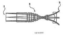
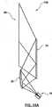
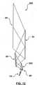
前面投影システム(フロントプロジェクションシステム)では投影機(プロジェクタ)と観察者は、表示面から観察者に反射する投影機からの画像と共に、表示面の同じ側に存在し、投影機からの画像は表示面で観察者に反射される。図1Aは、入力光学画像2を取り入れて、拡大された出力光学画像3を投影できる標準的な従来技術の8要素投影レンズ5を示す。図1Bは、表示面20の上に直接画像を投影するためにこの8要素投影レンズ5を使用する投影光エンジン6を示す。これは、画像が表示面20に垂直である直線軸10aに沿って生成されて投影される軸上(オンアクシス)投影システムの一例を示す。 In a front projection system (front projection system), the projector (projector) and the observer are present on the same side of the display surface with the image from the projector reflecting from the display surface to the viewer, and the image from the projector is displayed. Reflected by the observer at the surface. FIG. 1A shows a standard prior art 8-
背面投影システム(リアプロジェクションシステム)のためには、このデザインは、背面投影スクリーンキャビネット寸法に関する商業的要件に従うように、よりコンパクトにされなくてはならない。この「コンパクトさ」は、「投射比」に換算して定量化される。投影システムの投射比は、表示面20の対角線長D(図示せず)で除算された投影距離d(図1B参照)によって与えられる。対角線Dは、表示面20の相対する隅から測定される。投射比は、
投射比=d/D (1)
によって与えられる。For rear projection systems (rear projection systems), this design must be made more compact to comply with commercial requirements regarding rear projection screen cabinet dimensions. This “compactness” is quantified in terms of “projection ratio”. The projection ratio of the projection system is given by the projection distance d (see FIG. 1B) divided by the diagonal length D (not shown) of the
Projection ratio = d / D (1)
Given by.
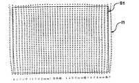
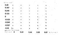
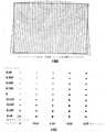
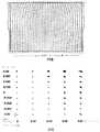
図1C、1Dに示すように、前面投影構成における一般的投影レンズ5は、典型的なスポットサイズ(すなわち隅における焦点ぼけ点画像)を有する低い歪みを持った画像を生成する。特に1480mm×834mmの寸法を有する表示面20と25.4mm、f/2.8の投影レンズ5とによって、中心で1mmスポット、隅で3mmスポットを有する投影画像が生成される。前面投影システムに関する妥当な設計目標は、中心で1ピクセルスパン(画素直径)以下、隅で2〜3ピクセルスパン未満の最小解像可能な焦点合せされたスポットサイズを持つことである。この特定の例では、マイクロディスプレイ画像形成装置におけるピクセルサイズと、離れた表示面への投影に起因する拡大とを考慮すると、表示面20におけるピクセルスパンは約1mmである。全レンズ歪みは、表示面20のスクリーンサイズ全面に亘って1%未満である。損失ピクセルと損失輝度(表示スクリーンをオーバーレイしないピクセルを消してその結果全体的輝度へのそれらのピクセルの寄与を失うことからくる)とを減らすために、歪みマップ(すなわち図1C)は矩形であって、利用可能表示領域を正確にオーバーレイすることが望ましい。更に図1Dのスポット図はまた、最小のスポットサイズ増を示し(表示の中心からより遠いピクセルにおいて)、また対称であることが望ましい。スポットサイズの増加を最小にすることは、点画像の焦点ぼけを最小にすることを意味する。 As shown in FIGS. 1C and 1D, the
コンパクトな投影システムを構築するに際してのもう一つの重要な設計目標は、投射比を最小にしながら良好な画像品質を達成することである(一部の設計者は投射比を計算する際に画像の対角線の代わりに幅を使用するので、投射比のどちらの定義が使用されているかを指定することが重要である)。投射比を最小にすることは、投影機とスクリーンとが背面投影型テレビジョンといった単一の機能ユニットに物理的に結合されている背面投影システムにとって特に重要である。このようなユニットでは、投射比を最小にすることは、表示面と投影光エンジンとを収容したキャビネットに関してより小さな奥行きを可能にする、より短い投影経路長を意味する。前面投影システムにおいて投射比を最小にすることは、スクリーンに極めて近く配置された投影機によって大きな画像が投影されることを可能にする。 Another important design goal in building a compact projection system is to achieve good image quality while minimizing the projection ratio (some designers have to calculate the image ratio when calculating the projection ratio). Since width is used instead of diagonal, it is important to specify which definition of projection ratio is used). Minimizing the projection ratio is particularly important for rear projection systems in which the projector and screen are physically coupled to a single functional unit such as a rear projection television. In such a unit, minimizing the projection ratio means a shorter projection path length that allows for a smaller depth with respect to the cabinet containing the display surface and the projection light engine. Minimizing the projection ratio in a front projection system allows a large image to be projected by a projector located very close to the screen.
背面投影表示システムにおけるキャビネット奥行きと奥行き削減は、表示対角線対キャビネット奥行きの比率、すなわちD対D比を測定することによって客観的に評価される。軸上投影と平面ミラーと光学だけの歪み修正手段とを使用する従来の構成は、約2.5〜3.5のD対D比を与える(例えば61”対角線対19.5”奥行き、あるいは55”対角線対18”奥行き、など)。 Cabinet depth and depth reduction in rear projection display systems is objectively evaluated by measuring the ratio of display diagonal to cabinet depth, ie, the D to D ratio. Conventional configurations using on-axis projection, plane mirrors, and optical-only distortion correction means provide a D to D ratio of about 2.5 to 3.5 (eg, 61 "diagonal pair 19.5" depth, or 55 "
キャビネット奥行きを減らすために従来技術の方法は、低い歪みを有する(光路を折り畳むための)平面ミラーと、投影経路長を減らすために、したがって投射比を減少させるために役立つ広視野(FOV)レンズとを組み合わせている。光学的幾何学構成(レンズタイプ、焦点距離、ミラー角度)を微調整することによって画像歪みは最小化され得る。従来技術の構成は、投影ビームに対して折返しミラー(単数または複数)を軸上に配置する。これは、キーストーン歪み(keystone distortion)を生成しないという利点を有する。しかし、大きなキャビネット奥行き削減を与えないこと、あるいはD対D比が増加しないという欠点がある。 Prior art methods to reduce cabinet depth include flat mirrors with low distortion (to fold the optical path) and wide field of view (FOV) lenses that help to reduce the projection path length and thus reduce the projection ratio. Is combined. Image distortion can be minimized by fine-tuning the optical geometry (lens type, focal length, mirror angle). The prior art arrangement places the folding mirror (s) on the axis relative to the projection beam. This has the advantage of not producing a keystone distortion. However, there is a drawback that it does not give a large cabinet depth reduction or does not increase the D to D ratio.
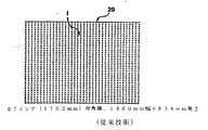
例えば図2Aは、投影光エンジン14と平面ミラー8と表示面20とを有する従来技術の投影システム6’を示す。これは、平面ミラーが折畳み光路を生成し、表示面20に対して角度αに在る軸上投影システムの一例である。この結果、Tというキャビネット奥行きが得られている。この投影システム6’は、表示面20上に投影される画像Iを示す図2Bに見られるように、キーストーン歪みを生じない。 For example, FIG. 2A shows a prior
従来技術の構成においてキャビネット奥行きを減らすための主要な方法は、軸上光路で短投射距離広角レンズを使用することである。これは、奥行き短縮を制限するという欠点を有し、キーストーン歪みが存在しなくても、この手法はなお、設計・製造の困難な光学要素を必要とする。光学的幾何学的な制約は、増大した糸巻き型歪曲または樽型歪曲およびキーストーン歪みとして現れる。従来技術のシステムの設計は、コストパフォーマンスとのトレードオフを満足させながら、必要とされる変調伝達関数(MTF)を達成すること、横の色に関して修正すること、レンズFナンバー仕様を満たすことと共に、これらの歪みを最小にするという要件によって大きく束縛されてきた。 The primary method for reducing cabinet depth in prior art configurations is to use short throw distance wide angle lenses in the on-axis optical path. This has the disadvantage of limiting depth reduction, and even without keystone distortion, this approach still requires optical elements that are difficult to design and manufacture. Optical geometric constraints appear as increased pincushion or barrel distortion and keystone distortion. Prior art system design along with achieving the required modulation transfer function (MTF), correcting for lateral color, meeting lens F-number specification, while satisfying cost performance tradeoffs Have been largely constrained by the requirement to minimize these distortions.
従来技術の背面投影システムは、高いコントラスト比を与えるために前面からスクリーンアセンブリに当たる光に対して(光吸収材料の使用によって)低い反射率を有するスクリーンアセンブリを使用する。これらのスクリーンアセンブリはまた、高い輝度を与えるために背面からスクリーンアセンブリに当たる光に関して(レンチキュラー・アレイの使用と光のコリメーションとによって)高い透過率を有する。光は、典型的には、スクリーンアセンブリの一部としてフレネルレンズを使用することによってコリメートされる。フレネルレンズは、軸上投影システムのための対称円形構造である(その光学的中心は、物理的中心に、あるいは投影光経路の軸上に位置する。所定の焦点距離のフレネルレンズは、同じ焦点距離の大きな円形の両凸レンズの代わりとなる。このようなフレネルレンズの直径は、大きくとも表示対角線の長さである。これらのフレネルレンズは、典型的には薄くて極めて柔軟であり、内部温度上昇によって膨張する。軸上投影システムに関する画像品質は、フレネルレンズの表面プロファイルの中心部分(光軸の周りの)における変化にあまり敏感ではない。不幸なことにこれらの対称フレネルレンズは、軸外れ(オフアクシス)RPシステムには使用できない。更にフレネルレンズは、光がスクリーンの底部に近い最小20±5度からスクリーンの最上部に近い最大60±5度まで変化する入射角でスクリーンに当たるので、高いD対D比を有する投影システムおいては慎重に設計されなくてはならない。したがってレンズ表面は、突き当たる光の入射角に対するコリメーション機能の感度のゆえに、極めて正確に維持されなくてはならない。
本発明は、統合フレネルコリメーションレンズを有する背面投影透過スクリーンを使用するコンパクトな背面投影システムである。本発明のもう一つの実施形態は、反射性スクリーンに極めて近く配置されたコンパクトな前面投影システムであり得る。特に本発明は、好都合にも光路長と投射比とを減らしながら、視覚的に正しい幾何学形状と最適な画像品質とを有する表示面に画像を光学的に投影するための軸外れ画像投影システムと方法とに関する。 The present invention is a compact rear projection system that uses a rear projection transmission screen with an integrated Fresnel collimation lens. Another embodiment of the present invention may be a compact front projection system positioned very close to the reflective screen. In particular, the present invention provides an off-axis image projection system for optically projecting an image onto a display surface having a visually correct geometric shape and optimal image quality while advantageously reducing the optical path length and projection ratio. And methods.
本投影システムは、画像処理ユニットと投影光エンジンと光反射アセンブリとを含む。画像処理ユニットは、解像度とアスペクト比とにおいて異なり得るディジタル入力画像データを受け取り、この入力画像データを投影光エンジンの正しいアスペクト比と解像度とに合わせて拡大縮小する。画像処理ユニットはまた、画像変調された光線が全光路を通るときに、光線がこの光路で光学的幾何学的歪みを受けて、知覚可能な歪みまたは不鮮明さを持たずに観察者に現れるように、後述する逆変換を使用する光変調器に送られるディジタル画像に歪み補正を適用する。言い換えれば歪み補正は、光変調器とスクリーンとの間の光路における歪みが、各ピクセルをスクリーン上のその所望位置に戻すように、画像変調器におけるすべての個別ピクセルが反対方向に十分遠くに動かされるようにする。投影光エンジンは、光変調マイクロディスプレイ装置(単数または複数)に光を生成させる信号に変換されるディジタルフォーマットで画像処理ユニットから歪み補正された画像データを受け取る。この光は、歪み補正された画像データに対応する光学画像を形成する。投影光エンジンは、投影幾何学形状と光反射アセンブリとの結果から生じるビーム拡大によるスポット焦点ぼけを補正する補正レンズを含むことができる。代替としてこの機能を与えるあつらえの投影レンズが使用可能である。 The projection system includes an image processing unit, a projection light engine, and a light reflecting assembly. The image processing unit receives digital input image data that may differ in resolution and aspect ratio, and scales the input image data to match the correct aspect ratio and resolution of the projection light engine. The image processing unit also ensures that when an image-modulated light beam passes through the entire light path, the light beam is subjected to optical geometric distortion in this light path and appears to the viewer without perceptible distortion or blurring. In addition, distortion correction is applied to a digital image sent to an optical modulator that uses inverse transformation, described below. In other words, distortion correction means that every individual pixel in the image modulator is moved far enough in the opposite direction so that distortion in the light path between the light modulator and the screen returns each pixel to its desired position on the screen. To be. The projection light engine receives the distortion corrected image data from the image processing unit in a digital format that is converted into a signal that causes the light modulating microdisplay device (s) to generate light. This light forms an optical image corresponding to the distortion corrected image data. The projection light engine may include a correction lens that corrects for spot defocus due to beam expansion resulting from the projection geometry and the light reflecting assembly. Alternatively, a custom projection lens that provides this function can be used.
光反射アセンブリは、歪み補正された光学画像を表示面の所定の領域に反射させるためにこの画像の光路に配置される。この光反射アセンブリは、表示面への反射を制御するための少なくとも一つの非球面ミラーを含む。この非球面ミラーは、表示面上で実質的に視覚的に正しい画像を形成することを助けるために、水平垂直両方向に滑らかに変化する曲率半径を持っている。これら投影光エンジンと光反射アセンブリは、光学的異常を最小にするように設計されており、また空間的精度の点では妥協し得る。画像処理ユニットは、投影光エンジンと光反射アセンブリとによって生成された組合せ空間歪みと、投影幾何学形状の変化と、アセンブリ位置合わせにおける回転的自由の3軸と平行移動的自由の2次元(上/下と左/右)とにおける誤差と、に関する最終的修正を実施できる。前後の平行移動的誤差は、焦点変化という結果になり、画像処理ユニットによっては修正できない。表示面は、高くそして変化する入射角で光を受けるように、また表示面に垂直な光を反射または透過するように設計される。 A light reflecting assembly is placed in the optical path of the image to reflect the distortion corrected optical image to a predetermined area of the display surface. The light reflecting assembly includes at least one aspheric mirror for controlling reflection on the display surface. The aspherical mirror has a radius of curvature that smoothly changes in both horizontal and vertical directions to help form a substantially visually correct image on the display surface. These projection light engines and light reflecting assemblies are designed to minimize optical anomalies and can be compromised in terms of spatial accuracy. The image processing unit has a combined spatial distortion generated by the projection light engine and the light-reflecting assembly, changes in the projection geometry, three axes of rotational freedom in assembly alignment and two dimensions of translational freedom (above). Final corrections for errors in / bottom and left / right). The back-and-forth translation error results in a change in focus and cannot be corrected by the image processing unit. The display surface is designed to receive light at a high and varying incident angle and to reflect or transmit light perpendicular to the display surface.
したがって第1の態様において、本発明は入力画像データに基づいて表示面に光学画像を表示するための軸外れ投影システムを提供する。この投影システムは、投影前に2次元の電子的に歪んだ画像データを生成するために、画素の2次元配置を示す前記入力画像データを受け取って前記入力画像データを電子的に歪ませるための画像処理ユニットと、画素の2次元配置を調整するための手段を有する表示装置を備え、前記画像処理ユニットに連結されると共に前記電子的に歪んだ画像データを受け取るように適応され、前記表示装置に前記電子的に歪んだ画像データに相当する2次元の歪んだ画像を調整し、前記2次元の歪んだ画像を投影して投影画像を生成する投影光エンジンと、前記投影画像を前記表示面上に導くように適応された前記投影光エンジンに連結され、少なくとも一つの湾曲ミラーを備えた光反射アセンブリと、を含み、前記電子的な歪みが、前記表示面上の前記投影画像において前記投影光エンジン及び前記光反射アセンブリで引き起こされる歪みを有する光学的幾何学的歪みが実質的に除去されるように作用する。Accordingly, in a first aspect, the present invention provides an off-axis projection system for displaying an optical image on a display surface based on input image data. The projection system receives the input image dataindicating a two-dimensional arrangement of pixelsand electronically distorts the input image data togenerate two-dimensional electronically distorted image data before projection.A display device comprising: an image processing unit; and a display device having means for adjusting a two-dimensional arrangement of pixels, the display device being coupled to the image processing unit and adapted to receive the electronically distorted image data A projection light enginefor adjusting a two-dimensional distorted image corresponding to the electronically distorted image data and projecting the two-dimensional distorted image to generate a projectionimage; and theprojection image on the display surface connected to adapted the projection light engine to direct above,it includes a light reflecting assemblyhaving at least one curvedmirror, wherein the electronic distortion, on the display surface Optical geometric distortionhaving distortion caused by the projection light engine and the optical reflection assembly in serial projected imageacts assubstantive removed.
本発明は、もう一つの態様において、入力画像データに基づいて軸外れ投影システムの表示面に光学画像を表示するための軸外れ投影方法を提供する。本方法は、投影前に2次元の電子的に歪んだ画像データを生成するために、画素の2次元配置を示す入力画像データを受け取って前記入力画像データを電子的に歪ませるステップと、画素の2次元配置を調整するための手段を有する表示装置を備えた投影光エンジンが、前記画像処理ユニットに連結されると共に前記電子的に歪んだ画像データを受け取るように適応され、前記表示装置に前記電子的に歪んだ画像データに相当する2次元の歪んだ画像を調整し、前記2次元の歪んだ画像を投影して投影画像を生成するステップと、前記投影光エンジンに連結されると共に前記投影画像を前記表示面上に導くように適応され、少なくとも一つの湾曲ミラーを備えた光反射アセンブリで前記投影画像を反射するステップと、を含み、前記電子的な歪みが、前記表示面上の前記投影画像において前記投影光エンジン及び前記光反射アセンブリで引き起こされる歪みを有する光学的幾何学的歪みが実質的に除去されるように作用する。In another aspect, the present invention provides an off-axis projection method for displaying an optical image on a display surface of an off-axis projection system based on input image data. The methodfor producing an electronically distorted image data of the two-dimensional before projection, the steps of Rudistort the input image data by receiving the input imagedata representing a two-dimensional arrangement of pixelselectronically,A projection light engine comprising a display device having means for adjusting a two-dimensional arrangement of pixels is coupled to the image processing unit and adapted to receive the electronically distorted image data, the display device Adjusting a two-dimensional distorted image corresponding to the electronically distorted image data, projecting the two-dimensional distorted image to generate a projection image, andbeing coupled to the projection light engine; wherein the adapting the projected image to direct onto the display surface,comprising the steps of reflectingthe projection image light reflectedassembly comprising at least one curved mirror,the, of the electronic Only the optical geometric distortionhaving distortion caused by the projection light engine and the optical reflection assembly in the projected image on the display surfaceacts assubstantive removed.
本発明のより良い理解のため、また本発明がどのように実施され得るかをより明確に示すために、本発明の例示的実施形態を示す下記の付属図面への参照が単に例として行われる。 For a better understanding of the present invention and to more clearly show how the present invention can be implemented, reference is made by way of example only to the following accompanying drawings that illustrate exemplary embodiments of the present invention. .
さて図3Aを参照すると、キャビネット厚さT(図2Aを参照)を減らす第1の試みは、角度αを減らすことを含み得る。したがって軸上投影システム6’と同じコンポーネントを有する投影システム6”(すなわち軸外れ投影システム)が示されているが、平面ミラー8は表示面20に関して、より浅い角度で配置されている。これは、キャビネット厚さをTという厚さからT’という厚さに減らすという望ましい効果を持っている。しかしながら、今度は結果として得られる画像は、軸外れ投影システム6”によって生成された画像I’が元の画像I(図2B参照)に関して歪められているキーストーン歪みを持っている(図3B参照)。このキーストーン歪みは、画像I’の最上部付近では画像I’を水平方向に引き伸ばしながら、画像I’の底部付近では画像I’を水平方向に縮めることを含んでいる。また画像I’は、垂直方向にも引き伸ばされる。 Referring now to FIG. 3A, a first attempt to reduce the cabinet thickness T (see FIG. 2A) may include reducing the angle α. Thus, although a
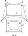
図4Aを参照すると、キャビネット厚さを減らすために、より小さなキャビネット内にシステムを嵌め込むように折り畳んだ光路と軸外れミラー配置とを使用する背面投影システム21が示されている。二つの平面ミラー33、35を使用する多重折畳みは、全投影経路長を収容しながら、より薄いキャビネットサイズを可能にしている。図示したように、投影される画像は、第2次平面ミラー35から第1次平面ミラー33に反射する。1次平面ミラー33は、表示面20の反対側の観察者4による観察のために、投影画像を表示面20の背面に反射する。しかしながら、この2平面ミラー背面投影構成はなお、実質的なキーストーン歪みを含む。図4Bは、どのようにして投影画像がスクリーンの底部でより小さくなり、スクリーンの最上部でより大きくなり(すなわち投影画像I1がスクリーン周辺長S1内に収まらない)、また大きく歪むかを示している。特に図4Bに示すようにこの背面投影構成は、65%のキーストーン歪みに関連している。また図4Cは、どのようにしてスポットサイズ(すなわち焦点ぼけ(デフォーカス))が表示面20の上部エッジに沿って約50mm(2〜3mmという所望レベルを遥かに超えている)になるかを示している。キーストーン歪みは、投影光エンジン14の投影レンズ5に対してマイクロディスプレイを下方にシフトすることによって幾分減らすことができ、また焦点ぼけは、投影レンズ5に対してマイクロディスプレイを傾けることによって減らすことができる。これは、図19〜20で更に詳細に示される。 Referring to FIG. 4A, a
図5、6は、本発明にしたがって構築された投影システム10を示す。投影システム10は、画像処理ユニット12と、投影光エンジン14と、画像源18によって与えられる入力画像を表す画像データを表示光学画像が無歪曲画像であるように表示面20への投影のための歪み補正された光学画像に変換する光反射アセンブリ16とを含む。 5 and 6 illustrate a
画像源18は、ビデオカメラ、パソコン、または必要とされるビデオ/グラフィックフォーマット(例えばYPrPb、RGB、DVIなど)で画像を生成することのできる他の如何なる装置でもあり得る。 The
画像処理ユニット12は、画像源18から入力画像データを受け取り、表示面20に表示される画像が歪みなしであるように、投影システム10における光学的歪みを補正するためにこのデータをディジタル処理でワーピング、または歪み補正する。画像処理ユニット12はまた、表示光学画像における如何なる明るさ/輝度の不均一性も修正する。画像処理ユニット12は、投影光エンジン14に与えられるディジタル画像データに電子的修正を加え、それによってデータのディジタル微調整を可能にしている。画像処理ユニット12の固有の機能は、更に詳細に論じられるであろう。 The
投影光エンジン14は、画像処理ユニット12から歪み補正されたディジタル画像データを受け取って、対応する歪み補正された光学画像を生成する。投影光エンジン14は、光発生ユニット22とマイクロディスプレイ24と投影光学系26とを備えている。光発生ユニット22(照明サブシステムとしても知られる)は、光源(例えば超高圧アーク灯、RGB発光ダイオードまたはRGBレーザー)、色分解プリズム、放物面リフレクタ、インテグレータ(ミラーボックス)ロッドおよび/またはインテグレータ/コリメータといったコンポーネント(図示せず)を含む。マイクロディスプレイ24は、適当なカラーマネージメント(色管理)システム(すなわちカラーホイール、偏光プリズム、カラー選択フィルタなど)を有する商業的に入手可能な任意のマイクロディスプレイに基づく光変調サブシステム(例えばマイクロディスプレイ固有インタフェースASICを含む1パネル型または3パネル型LCD、1または2または3パネル型DLP(登録商標)、または1パネルまたは3パネル型LCOSなど)であり得る。マイクロディスプレイ装置24は、画像処理ユニット12によって生成された歪み補正されたディジタル画像データにしたがって反射/透過光を変調することによって光学画像を生成するために使用される。実際に照明サブシステムは、適切なカラーマネージメントおよび/または偏光再生コンポーネントによって光変調マイクロディスプレイ装置(単数または複数)を均一に照明するように形作られた光ビームを生成する。光変調マイクロディスプレイ装置(単数またな複数)は、ディジタル画像データを光学画像に変換するために照明サブシステムの前に配置される。投影光学系26は、歪み補正された画像を投影して焦点合わせするレンズからなる。 The
投影光学系26は、固定焦点距離の長投射距離もしくは短投射距離レンズ、または可変焦点距離のズームレンズからなり得る。また投影光学系26の投影角は、通常のまたは広い視野(FOV)であり得る。投影光学系26と湾曲ミラーとにおける如何なる歪みもディジタル画像処理によって修正されるので、本発明は投影光学系26が歪みなしであることを必要としない。投影光学系26はまた、投影レンズ25に搭載され、したがって投影レンズ25と光反射アセンブリ16との間の歪み補正された光学画像の光路に配置される補正レンズ49を含むことができる。補正レンズ49の機能は、更に論じられるであろう。投影光エンジン14の前面エッジの部分は、参照数字14aによって表される。補正レンズ49は、もし投影光学系26が以下更に論じられるように注文により構築されれば、除去され得る。 The projection
光反射アセンブリ16は、歪み補正された光学画像からなる投影光エンジン14からの光ビームを受け取って、それを表示面20に反射する。図6は、更に詳細に光反射アセンブリ16の所定の要素を示す。図示したように光反射アセンブリ16は、非球面ミラー39と一次平面ミラー33とからなる。非球面ミラー39は、光路を折り畳むために一次平面ミラー33と共同して使用される非球面非対称(または回転非対称)湾曲ミラーである。このようなミラーは、キーストーン歪みそれ自身が非対称であるので、ひどい(高いD対D比で現れる種類の)キーストーン歪みを補正するために最も効果的で直接的な方法である。キーストーン歪みにおいては、画像の底部に対して画像の最上部における画像の異なる拡大率が存在する。従来技術の方法は、すべての歪みが光学的手段によって修正されなくてはならないという要件のために、キーストーン歪みを修正するようにオフセットされたマイクロディスプレイと対称なミラー/レンズとを使用するだけであるので、キーストーン歪みの量(及び、したがってD対D比の改善)において制約される。非球面ミラー39の主要目的は、軸外れ投影による歪みを減らすことと、すべての利用可能なマイクロディスプレイピクセルと照明源からの光との使用を可能にすることである。非球面ミラー39はまた、マイクロディスプレイ・シフトによって修正されない如何なる残りの歪みをも修正するために、マイクロディスプレイ・シフトを適用する投影システムにおいても使用可能である。投影光学系26の補正レンズ49は、上述のようにビーム幅発散を修正するため、およびこれから論じられるように関連する焦点ぼけ歪みを制御するために、投影レンズ25と非球面ミラー39との間の歪み補正された光学画像の光路に配置される。補正レンズ49はまた、非球面的に湾曲した回転非対称レンズである。 The
表示面20は、高い、そして変化する入射角で光を受け取って、表示面20に垂直な光を反射または透過させるように設計されている。表示面20は、前面投影システムでは反射性であり、背面投影システムでは透過性である。従来の背面投影システムでは、垂直でない角度で表示面20に当たる光を受けて、その方向を観察者に向けて表示面20の平面を通して垂直に出て行くように、言い換えれば光をコリメートするように変化させるために、フレネルレンズが使用される。従来の背面投影システムでは、フレネルレンズの中心は、表示面の中心にあり、表示面上に放射状に対称な入射角分布が存在する。 The
本発明にしたがって設計されたRP(背面投影)軸外れシステムでは、フレネルレンズは同様に必要とされるであろうが、それは軸外れ投影幾何学構造のゆえに表示面に当たる光の入射角の非対称分布を取り扱わなくてはならない。このことは、フレネルレンズの中心が表示面の中心からかなり下方にオフセットされざるを得なくし、このオフセットの程度はシステムのD対D比(使用される軸外れ幾何学形状の量)に依存している。したがって軸外れ投影システムで使用されるフレネルレンズは対称ではない。これらの非対称フレネルレンズは、特にそのために設計された軸外れ光路を含む投影光の遥かに大きな円錐形から光をコリメートするように設計されなくてはならない。実際に、より高いD対D比を有するシステムでは投影軸は、より大きく傾けられており、より大きなキーストーン歪みを修正する必要がある。これは、より幅広い円錐状の光が表示面の底部と最上部との間で光の入射角のより大きな広がりを持って、マイクロディスプレイから発散することを意味する。この光円錐の光軸は、フレネルレンズの中心を通り抜けなければならず、この光学的要件を満足させるために、フレネルレンズの中心はより大きく下方にオフセットされる。極端な軸外れ構成を有する投影システムでは、フレネルレンズの光学的中心は完全にスクリーンから離れる可能性がある。その結果、フレネルレンズの直径は、スクリーンの対角線より遥かに大きくなり、スクリーンと貼り合わされるように矩形片がそこから切り取られる。明らかに、もし単に1個の使用可能なフレネルレンズ・セグメントがより大きな直径の構造体から抽出され得るならば、レンズのコストはより高くなる。ある幾つかの非対称フレネルレンズの設計では、2個以上の使用可能なレンズセグメントが基本的な大直径の完全なフレネルレンズから切り取られることができ、フレネルレンズを作製するために使用される型を加工するコストを償却する助けとなる。 In an RP (Rear Projection) off-axis system designed in accordance with the present invention, a Fresnel lens will be required as well, which is an asymmetric distribution of the incident angle of light striking the display surface because of the off-axis projection geometry. Must handle. This forces the center of the Fresnel lens to be offset significantly downward from the center of the display surface, and the degree of this offset depends on the D to D ratio of the system (the amount of off-axis geometry used). ing. Therefore, Fresnel lenses used in off-axis projection systems are not symmetric. These asymmetric Fresnel lenses must be specifically designed to collimate light from a much larger cone of projected light, including off-axis optical paths designed for it. In fact, in systems with higher D to D ratios, the projection axis is tilted more and needs to correct larger keystone distortion. This means that a wider cone of light diverges from the microdisplay with a greater spread of the incident angle of light between the bottom and top of the display surface. The optical axis of the light cone must pass through the center of the Fresnel lens, and the center of the Fresnel lens is offset much more downward to satisfy this optical requirement. In a projection system having an extreme off-axis configuration, the optical center of the Fresnel lens can be completely off the screen. As a result, the diameter of the Fresnel lens is much larger than the diagonal of the screen, and a rectangular piece is cut from it so as to be bonded to the screen. Obviously, the cost of the lens is higher if only one usable Fresnel lens segment can be extracted from a larger diameter structure. In some asymmetric Fresnel lens designs, two or more usable lens segments can be cut from a basic large diameter full Fresnel lens, and the mold used to make the Fresnel lens Helps to amortize processing costs.
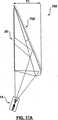
図7A〜7Cは、図6の非球面ミラー39の表面曲率を示す。非球面ミラー39は、投影システム10の軸外れの性質から結果的に生じるキーストーン歪みを修正するために導入されている。非球面ミラー39は、凹面からの画像の反射は画像を縮小し、凸面からの画像の反射は画像を拡大するであろうという知識に基づいて設計される。例えば図3Bで画像は、表示面の最上部では表示面の幅を超えて水平方向に拡大している。更に画像は、表示面の底部で表示面の幅より狭く水平方向に縮小している。凹面の上部を有するミラーは表示面に合うように画像を縮小させ得るであろうが、もしそれが凸面の下部を持つならば、同じミラーは表示面の底部に合うように画像を拡大できるであろう。実際に軸外れ投影方式によれば、画像の最上部が水平方向の表示面幅以下になるように投影システムを表示面に少し近づけることが、またしたがってミラー形状を調整することが好ましい。これは、投影距離を短縮する(折り畳まれた幾何学構成においてより薄いキャビネット厚さに導くことができる)ということと、ミラーが凹面から凸面への遷移を持つ代わりに凸面だけであるのでミラープロファイルがより製造し易い、という二重の利益を有する。投影距離を短縮する際、投影光エンジンのレンズは、より広角のレンズになり、これは設計がより難しく、修正される必要のあるより大きな球面収差を有する。その結果、最適な構成を決定するために、投影距離と投影レンズと非球面ミラー39の曲率との幾つかの異なる組合せを繰り返し試すことが有益となる。 7A-7C show the surface curvature of the
したがって本発明の非球面ミラー39は、表示面20の最上部で極めて僅かに水平方向に拡大する効果(すなわち投影経路が短縮されている)を与えるための水平方向に軽く凸面の上部と、表示面20の底部を水平方向により大きな度合いに拡大するための水平方向により強く凸面の下部と、を持つように設計される。非球面ミラー39はまた、キーストーン歪みの垂直方向の拡張を補正するために垂直方向に凹面になっている。したがって、非球面ミラー39は、垂直方向の凹面と、より強い凸面から平面またはより弱い凸面に変化する水平方向の表面とを有する。明確さのために、図7Aは、非球面ミラー39が作られる型の水平方向の曲率を示し、図7Bは非球面ミラー39の型の垂直方向の曲率を示す。図7Cは、このページ内に延びる水平方向(すなわちY軸に沿った)と、左から右へ延びる垂直方向と、z軸によって表される曲率の高さ(あるいは厚さ)とを有する非球面ミラー39の曲率の斜視図を示す。ミラーの実際の活性領域は、図7Cに示されたものより小さいが、この図は非球面ミラー39の表面プロファイルを記述する係数を変える効果を見るためには有用である。非球面ミラー39の水平方向の曲率半径は、最上部における大きな正の値(すなわち小さな曲率)から底部におけるより小さな正の値(すなわち大きな曲率)へ遷移する。垂直方向の曲率半径は、キーストーン歪みに起因する垂直方向の拡大縮小誤差を修正するように選択される。 Therefore, the
非球面ミラー39の全体的形状は、最初と最後の半径と遷移の割合とによって決定され、また前述の説明からそれは横方向には垂直軸の周りに対称であるが、明らかに回転非対称である。非球面ミラー39の固有の表面プロファイルは、対応する投影レンズの設計と、電子的手段によって修正されるべき所望の歪みと、所望の有効表示解像度と、キャビネット奥行きと、をトレードオフする(相殺取引する)ことによって選択される。したがって、垂直方向に凹面であって、ミラーの上部での凹面からミラーの下部に沿って平面、凸面へと変化する水平方向の曲率を有する非球面ミラーが設計され得る。例えば従来のように構成されたシステムで使用される同じ投影レンズを使用したいと思っている背面投影テレビジョン(RPTV)製造業者は、補正レンズを必要とするであろうし、また既存の投影レンズの物理的寸法によって課せられる制約によって、この用途のために新しい投影レンズを喜んで設計しようとしている他のRPTV製造業者とは異なる対角線対奥行き比率(およびキャビネット奥行き)を選択するかも知れない。もう一つの例は、キャビネットの寸法を制約するかも知れない、したがって間接的に非球面ミラー39の規定を制約するかもしれない平面ミラーの在庫品を有するRPTV製造業者である。 The overall shape of the
もしキャビネット奥行きが縮小されれば、非球面ミラー39と投影レンズ5との間の角度はより浅くなり、修正される必要のあるキーストーン歪みの増大につながる。その結果、非球面ミラー39の曲率は、より激しい上部の水平方向の拡大と、より激しい下部の水平方向の縮小と、より激しい垂直方向の拡大とを修正する必要があるので、より極端になる必要がある。非球面ミラー39は、より大きな曲率に適応するために、より大きく、より厚くなる。この場合、補正レンズ49はまた、非球面ミラー39の増大した曲率のために生じた更なる焦点ぼけ効果を修正するために、より大きな曲率を組み入れるように修正される。 If the cabinet depth is reduced, the angle between the
非球面ミラー39は、軸外れ投影システムにおけるキーストーン歪みをある程度または完全に修正できる。このようなシステムでは、平面ミラーは修正を提供しない。減少したキーストーン歪みは、画像を拡大する(より大きな、またはより小さな度合いで水平方向に)ために非球面ミラー39の凸面部分を使用し、画像を垂直方向に縮小するためにミラーの凹面部分使用することによって達成される。曲率の符号(凸面または凹面)と大きさとを滑らかに変化させることによって、キーストーン形状の歪み・プロットは、多かれ少なかれ矩形の歪み・プロットに変換される。もし非球面ミラー39と補正レンズ49が共に適切に設計されれば、画像処理ユニット12が表示面20のエッジに近いピクセルの品質(すなわち輝度と焦点)を維持することは遥かに容易になる。しかしながら非球面ミラー39はまた、像面湾曲の複合問題、すなわち画像の中心は妥当なMTFと焦点を持つがエッジの画像は焦点ぼけと低下したMTFを経験するというスポットサイズ/焦点問題に導く。 The
図8A〜8Cは、投影レンズ5によって非球面ミラー39に投影される光ビームの焦点ぼけ(すなわちビームの拡大)を減らすために(投影レンズ25に対してマイクロディスプレイ装置24をまたはその逆をシフトして傾けることと一緒に)使用される図6の補正レンズ49の表面曲率を示す。補正レンズ49はまた、非球面ミラー39の曲率に対応し、また投影システム10で使用されている投影レンズ5と共に使用されるために設計された非球面的に湾曲した回転非対称なレンズである。特に補正レンズ49は、図6に示すように投影レンズ5の前に配置されるように設計される。図8Aは水平方向の補正レンズ49の曲率を示し、図8Bは垂直方向の補正レンズ49の曲率を示す。図8Cは、左から右へ示された水平方向と、そのページ内に延びる(すなわちY軸に沿った)垂直方向と、z軸によって表される曲率の高さ(あるいは厚さ)とを有する補正レンズ49の曲率の斜視図を示す。補正レンズ49の形状は、非球面ミラー39の形状に類似しており、また垂直軸の周りに回転非対称で、横方向に対称であるであろう。特に補正レンズ49は、小さな曲率半径から大きな曲率半径に遷移し、また垂直方向に凹面形状を持つ水平方向に凸面の円筒形レンズである。しかしながら補正レンズ49は、より平坦である(すなわち、水平垂直両方向に、より大きな曲率半径を持つ)。 FIGS. 8A-8C shift the
補正レンズ49は、非球面ミラー39より大きな曲率半径で形成されており、ビーム幅拡大を修正し、投影レンズ5の特性を補正する。補正レンズ49の使用はまた、現在利用可能な投影レンズ5が本発明の投影システム10内での使用に適応させられること(すなわち更新されること)を可能にし、現在利用可能な投影レンズ5に最小性能・寸法基準(すなわちレンズスピード(開放径)、MTF、より小さな囲い内に収まる能力など)を与える。補正レンズ機能を含み、したがって別個の補正レンズ・コンポーネントを必要とせず、適当な嵌め込みを保証するシステムのための注文製の投影レンズが開発されることは可能であり、これはより詳細に後述される。また投影レンズ5と補正レンズ49と非球面ミラー39と軸外れ投影幾何学構造と設置の位置合わせ不良とに起因する残りの未修正歪みの組合せを修正する電子的修正を与えるために、画像処理ユニット12が使用されることは理解されるべきである。したがって画像処理ユニット12は、投影システム10における如何なる物理的不正確さまたは位置合わせ不良も補正できる更なる自由度を与える。 The
図6〜8に関して、種々コンポーネントに関する例示的寸法が与えられるであろう。補正レンズ49に関しては、第1の表面サグは4.58mmであり、第2の表面は平面であり、投影レンズにおける最後のレンズ面からの距離は11mmである(中心光線)。湾曲ミラー39に関しては、ミラーサグは33.5mmであり、傾き角は46.4度であり、投影レンズにおける最後の補正レンズ表面からの距離は201.7239mm(中心光線)であり、隅のX、Y座標はmm単位で、(295.528198、276.941671)、(141.557812、−87.435980)、(−141.557812、−87.435980)、(−295.528198、276.941671)である。ミラー33に関しては、傾き角は+51.2度であり、湾曲ミラー39からの距離は298.775mm(中心光線)であり、隅のX、Y座標はmm単位で、(713.058886、579.509103)、(611.018382、−235.682721)、(−611.018382、−235.682721)、(−713.058886、579.509103)である。表示面20に関しては、傾き角は0度であり、ミラー33からの距離は384.2278mm(中心光線)であり、サイズは幅1480mm×高さ834mm、対角線1702mmである。 6-8, exemplary dimensions for various components will be given. For the
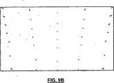
さて図9Bを参照すると、平面ミラー33の上の画像の焦点スポット図が示されている。画像は、マイクロディスプレイ装置24によって生成され、補正レンズ49と非球面ミラー39とを介して投影光エンジン14によって投影された点の矩形5×7マトリックスであった。非球面ミラー39の底部付近で凸面曲率の度合いを増加させることは、図9Bの底部付近で点が広がるようにするが、非球面ミラー39の最上部付近で凹面曲率の度合いを増加させると、図9Bの最上部付近で点が圧縮される。図9Bが如何なる電子的修正からの効果も持たない焦点スポットの振舞いを示すことは留意されるべきである。 Referring now to FIG. 9B, a focal spot diagram of the image on the
非球面ミラー39の曲率は、キーストーン歪みを修正しようと試み、平面ミラー33の表面に見られるように歪み低減の改善が見られる。焦点スポット図は、画像のエッジ付近の点に関してはまだ僅かなキーストーン効果ならびに焦点ぼけ効果が存在することを示している。この僅かなキーストーン効果は、平面ミラー33からある一定の距離に表示面20を配置することによって修正され得る。しかしながら、もし表示面20が平面ミラー33から遠く離れた距離に配置されれば、逆のキーストーン歪みと増加した焦点ぼけとが発生する。しかし、この僅かなキーストーン効果を修正するもう一つの手法は、以下に説明されるように電子的手段によって行われ得る。 The curvature of the
さて図5、6、9Aを参照すると、画像処理ユニット12は、表示光学画像が歪みなしになるような仕方で、入力ディジタル画像に歪み補正を幾何学的に加えるために使用される。 Referring now to FIGS. 5, 6, and 9A, the
特に図9Aは、非球面ミラー39といった湾曲ミラーでの理想的画像44の反射の結果生じる歪んだ画像40の例を与える。非球面ミラー39はキーストーン歪みを修正するが、修正されるべきいくらかの残留歪みがなお存在する。また湾曲ミラーで反射するときにその湾曲ミラーに起因する歪みを修正または補正し、その結果、表示面20に投影される理想的画像44を与える歪み補正された画像42が示されている。すなわち歪み補正された画像42が湾曲ミラーで反射されるとき、理想画像44が表示面20に投影されるであろう。特に如何なる修正も存在しない場合、理想画像ABCDは図示したように写像される隅/境界を有する湾曲した「台形」EFGHとして表示面20上に表示されるであろう。「台形」IJKLによって示されるように逆の仕方で画像を補正することによって、表示される最終的画像は、スクリーン/理想画像ABCDと正確に一致し、したがって歪みなしになるであろう。 In particular, FIG. 9A provides an example of a
したがって、投影システム10は、投影光エンジン14と関連反射(ミラー)光学系(図示せず)とによって導入された幾何学的歪み(図示せず)の逆である幾何学的変換にしたがって入力画像を歪み補正するために画像処理ユニット12を使用する。もし投影システム10内で得られた全歪み(レンズ/ミラーに起因する)が変換Fによって表されるならば、画像はF-1にしたがって歪み補正され、また下記の関係が存在する:
表示画像=F(F-1(入力画像))=入力画像 (2)
したがって画像処理ユニット12は、歪みなしの表示画像のための要件に関連する制約からシステムを本質的に「解放する」。歪みをディジタルに修正する能力は、光学的幾何学形状と光学要素(湾曲ミラーが回転非対称であるか否かにかかわらず、ミラーとレンズの角度、タイプなどといった)が特定の設計目標の必要にしたがって変化しうることを意味する。画像処理ユニット12によって与えられる幾何学的修正なしでは、種々の光学的処理ステップによって、表示画像内の歪みが生じる結果になるであろう。画像処理ユニット12によって加えられる歪み補正は、本質的に、入力画像データの再サンプリング/フィルタリングである。ピクセルは、ピクセル位置が受ける幾何学変換を与えるF-1にしたがって再サンプリングされる。変換F-1は種々の光学要素の空間的変換特性から決定され得る。画像処理ユニット12の仕様は、F-1が指定されることを必要とするフォーマット(例えば2次元表面、1次元多項式など)を決定するであろう。Thus, the
Display image = F (F−1 (input image)) = input image (2)
Thus, the
画像処理ユニット12はまた、明るさあるいは輝度の不均一性を修正するためにも使用される。表示面20上の表示画像は、投影光エンジンコンポーネント(例えば光発生ユニット、レンズ口径食(けられ)など)の限界に起因する、または光路の特性に起因する明るさのばらつきを持つ可能性がある。特に、表示面20上で照明される点またはセクションは、反射と補正レンズの屈折とを含む全経路を考えると、投影レンズから異なる距離を進む光によって照明される。表示画像の点またはセクションに当たる光の強度は、光によって走行される距離の二乗に逆比例して変化するので、これは表示画像内における明るさのばらつきにつながる。軸外れ投影システムでは、スクリーンの最上部に当たる光線の進む光路長と、スクリーンの底部に当たる光線の進む光路長とにはより著しい差異が存在する。その結果、明るさのばらつきは、軸上投影システムよりむしろ軸外れ投影システムに関して、より大きくなる。 The
画像処理ユニット12は、最終画像が均一な明るさで表示され得るように、投影に先立ってピクセル輝度を予め調整するために使用される。ピクセル輝度は、予め決められたマップ、F-1に類似の例えばG-1にしたがって色空間で予め調整され、表示面20におけるピクセルの位置を与える。このマップは、色空間で動作するだけであって、更なるフィルタリングは必要とされない(すなわちピクセルの位置ではなく、ピクセルの色値だけが調整される)。F-1に関してG-1は、種々の光学要素と光路との明るさ/輝度変換特性から決定され得る。画像処理ユニット12は、各ピクセルの色値にG-1を適用するであろう。単純なケースは、線形関数:G-1(O)=αO+βによって与えられる。ここでOはRGB色値であり、関数パラメータαとβはすべてのピクセルに関して一定である。投影システム10の電子的修正は、如何なる関連歪みもレンズの光学特性を整合させることによるよりもむしろ、予めワーピングすることによって除去されるので、光学レンズのより柔軟な選択を可能にする。特に同じサイズの画像を投影できる広角レンズが使用され得るが、より短い投影距離では投射比の減少に際して別の変数を与える。焦点問題(幾何学的問題とは反対の)は幾何学的歪み補正によっては修正されることができず、なお適当なレンズの選択によって光学的に取り組まれることを必要としていることに留意されたい。The
画像処理ユニット12によって達成される一般的電子的幾何学修正なしでは、投影システム10は、全体的画像歪みが許容可能であることを保証するように設計されなければならない。このような設計の制約は、湾曲ミラーと軸外れ投影(キーストーン効果)と広角レンズとの歪曲効果によって問題となり得る。本発明の電子的修正の使用は、投影システムに関する設計の制約から除去されるべき幾何学的歪み(ならびに輝度の不均一性)を見込んでおり、またその代わりにこれらの以前の制約は、設計「自由度」であると考えることができる。したがって光路の画像歪みは、他の収差を改善するために自由に修正され得る。更に入力信号の(歪み補正を介した)ディジタル修正は、これを補正するために使用でき、したがって歪曲のない画像が観察スクリーン上に生成され得る。 Without the general electronic geometry correction achieved by the
各々が固有の光のパスバンド、例えばR、G、B上で機能する3個の独立した画像処理ユニットを備えることによって、これらのパスバンドの各々に関する歪み補正特性が個別に調整され得ることは、留意されるべきである。これは、光の異なる波長に関して異なる値を持つ光学効果に、例えば屈折率に起因する横の色シフト、あるいは色収差といった問題の修正を見込んでいる。この手法を利用するために、光変調器がこれらによって変調された光の別々のパスバンドに同期する固有の補正処理を受けるように、光源において関心のあるパスバンドを分離する手段(例えばカラーバンドパスフィルタ)が備えられなくてはならない。フィールド順次(フィールドシーケンス)または3パネル並行光変調方式の両者ともこの手法に従う。これらの色空間で3色以上を使用する方式は同様に取り扱われ得る。この手法は、処理コストは絶えず低下しつつあるが光学系と労働コスト(位置合わせに含まれる)は増加しつつあるので、エレクトロニクスのコストと光学系および位置合わせコストをトレードオフして、ますます費用効率的になる見込みがある。もし輝度補正も各パスバンドに適用されれば、照明源(例えば超高圧ガスと小さなアークとを使用する高強度放電光)のスペクトル特性は、より望ましい特性(例えばピークを表す代わりにより均一な)を持つように調整され得る。 By providing three independent image processing units, each functioning on a unique light passband, eg R, G, B, the distortion correction characteristics for each of these passbands can be individually adjusted. Should be noted. This allows for correction of problems such as lateral color shift or chromatic aberration due to refractive index, for example, for optical effects having different values for different wavelengths of light. To take advantage of this approach, means for separating the passbands of interest at the light source (eg, color bands) so that the light modulators are subjected to a unique correction process that is synchronized to the separate passbands of the light modulated by them. Pass filter) must be provided. Both field sequential and three panel parallel light modulation schemes follow this approach. Systems that use more than two colors in these color spaces can be handled similarly. This approach increasingly trades off electronics and optical and alignment costs, as processing costs are continually decreasing but optics and labor costs (included in alignment) are increasing Expect to be cost effective. If brightness correction is also applied to each passband, the spectral characteristics of the illumination source (eg, high intensity discharge light using an ultra high pressure gas and a small arc) are more desirable characteristics (eg, more uniform instead of representing peaks) Can be adjusted to have
反射のために湾曲ミラーを使用することは、減少したキーストーン効果と糸巻き型/樽型効果との組合せにしたがって、なお歪められているスクリーン画像という結果をもたらす。したがって単に光学要素の選択的配置によってこれらのタイプの歪みを補正することは、極めて困難である。投影システム10の電子的幾何学的修正によって、これらの歪みは除去され得る。再び図9Aを参照すると、湾曲ミラーの反射によって発生する可能性のある歪んだスクリーン画像40と、幾何学的歪みを修正するために役立つ対応する歪み補正された画像42との一例が示されている。しかし、反射光学系アセンブリ16内で湾曲ミラーを使用する利点は、マイクロディスプレイ内の利用可能なピクセルの大部分またはすべての使用を維持しながら、キーストーン歪みが低減され得ることである。 Using a curved mirror for reflection results in a screen image that is still distorted according to a combination of reduced keystone and pincushion / barrel effects. It is therefore very difficult to correct these types of distortions simply by selective placement of optical elements. These distortions can be removed by electronic geometric modification of the
さて再び図5、6を参照すると、画像源18は画像処理ユニット12にディジタル入力画像データを供給し、そして、この画像データは適当な歪み補正された画像が生成されるまで画像処理ユニット12によって処理される。それから、歪み補正されたディジタル画像データは、光変調と、それに続く点Pにおける投影レンズ5による光反射アセンブリ16への投影のために投影光エンジン14に供給される。歪み補正された光学画像は、レンズにおいて(後述のようにレンズのシフトおよび/または傾きばかりでなく球面収差などから)歪められ、それから非球面ミラー39によって最初に反射されるが、画像が観察者4による観察のために光反射アセンブリ16の一次平面ミラー33を通って表示面20に達した後に画像が歪みなく見えるように、軸外れ角からのキーストーン歪みは画像を適当に満たし、湾曲面から反射することからの歪みは画像の最終的修正を行う。 5 and 6,
投影光エンジン14は、画像処理ユニット12から歪み補正されたディジタル画像データを受け入れて、非球面ミラー39によって導入される焦点ぼけを減少させるために使用される補正レンズ49を通り抜ける変調された光ビームを生成する。補正レンズ49は、投影レンズ5と非球面ミラー39の特性に起因するビーム幅拡大を修正する。投影される画像が補正レンズ49をいったん通り抜けると、画像は非球面レンズ39に当たり、それによって反射される。反射された画像は、それから、歪み補正された画像を表示面20(EからFに延びる)上に反射する一次平面ミラー33(AからBに延びる)に当たる。非球面ミラー39は、よりきつい凸面状の円筒面からよりゆるい凸面状の円筒面に徐々に変化するので、一次平面ミラー33に与えられる投影画像はキーストーン歪みの効果に関して、すなわち表示面の最上部から表示面の底部への水平方向の拡大縮小の変化に関して、ある程度修正される。更に非球面ミラー39の凹面状の垂直方向の曲率は、キーストーン歪みによる画像の垂直方向の拡大をある程度まで修正する。非球面ミラー39のある程度の歪み修正は、画像処理ユニット12が位置合わせ不良ばかりでなく残留歪みも補正するために電子的修正を行うので、問題でない。これは、位置合わせ不良の修正のための電子的手段が使用されない従来技術と対照的である。むしろ従来技術は、初期組立て時の正しい位置合わせと、機械的振動と温度変化との下における連続した位置合わせとを保証するために、精巧な光学的機械的熱的手法を使用している。 The
4個の点と、これらの点が一次平面スクリーン33上で定義する台形は、スクリーンの平面内の「台形」(湾曲面からの反射によって今は湾曲している)によって囲まれた領域が表示面20上でこのスクリーンを完全に取り囲むような仕方で反射されなくてはならない(台形EFGHがスクリーンABCDを完全に取り囲む図9Aに示すように)。これは、画像処理ユニット12による電子的修正の後に表示画像が表示面20上で矩形スクリーンを正確にカバーすることを保証する。 The four points and the trapezoid that these points define on the
もう一つの手法は、光が全光路を通過した後にスクリーンにおいて十分な解像度を維持する予め定義された歪み依存の形状に合うように形作られた複数ピクセルを有する投影光エンジン14の光変調表示装置を設計することである。この形状は、マイクロディスプレイ装置に突き当たる光ビームが変調された後に光ビームが投影レンズを通り抜けて、湾曲ミラーから反射し、表示面の全矩形範囲をオーバーレイする適当なアスペクト比を持って表示面に当たるとような形状である。利用可能な光の最適な使用のために、マイクロディスプレイに突き当たる光ビームは、マイクロディスプレイの形状に従うように形作られ得る。これは、例えばマイクロディスプレイ表面に似せて形作られた全内面反射インテグレータロッドを使用することによって達成され得る。 Another approach is to provide a light modulation display device for a
説明のために、本発明の投影システム10内の補正レンズ49の重要性は、投影システム10と、唯一の違いが補正レンズ49を持たないことである類似の投影システム100(両システムとも従来の投影レンズを使用する)との間の性能比較から見ることができる。投影システム100は図10Aに示されており、種々の動作結果が図10B、10Cに示されている。特に補正レンズ49の使用なしでは、歪み・プロット(図10B参照)はキーストーン歪みの比較的妥当なレベル(非球面ミラー39の使用により)を示すが、図10Cは焦点ぼけがひどいことを示すということが分かる。特に図10Cは、焦点スポットが表示面20の中心では約5mm(5ピクセルスパン(画素直径))であって、表示面20の周辺のエッジでは約30mm(30ピクセルスパン)であることを示している。焦点スポットサイズは表示面20の周辺エッジで20mmを超えており、これは典型的な投影システムの焦点スポットサイズ要件を満たしていない。この場合、投影レンズは補正レンズ49の特性を含むように設計され得る。図10B、10Cに関しては、電子的修正は使用されなかった。 For purposes of explanation, the importance of the
これに反して図11A、11Bに示すように、投影システム10の性能は、補正レンズ49が導入されて投影レンズ5の前に配置されるときに、著しく優れたものになる。特に、焦点スポットはすべて、許容可能な性能のために必要とされるように、スクリーン投影領域全面に亘って4mm(4ピクセルスパン)未満になることが、図11Bから分かる。実際に、焦点スポットサイズは2〜5mmの範囲にある。しかしながら、図11Aに示すように、補正レンズ49によって少量の更なるキーストーン歪みが再導入されることは留意されるべきである。この少量の歪みは、もう一つの設計の繰り返しによって減らすことができる。特に非球面ミラー39の表面は補正レンズ49の存在のために再最適化されることができ、補正レンズ49はまた非球面ミラー39の新しく繰り返される規定を使用して再最適化され得る。図11A、11Bに関しては、電子的修正は使用されなかった。 On the other hand, as shown in FIGS. 11A and 11B, the performance of the
代替として、もし投影光エンジンの投影レンズが前述のように非球面ミラー39を補正するように設計されれば、補正レンズ49は必要とされない。これは、投影光エンジンの既存のレンズ要素の一つに補正レンズ49の表面プロファイルを適用することによって遂行される。好適な候補は、既存のプラスチック成形された非球面レンズ要素である。これは、それだけでは完全な解を与えないであろうが、所望の表面プロファイルのための良好な一次近似を与えるであろう。更なる最適化は、補正レンズと組み合わされた既存のレンズの組合せより良好であるしつらえの投影レンズを与えることができる。 Alternatively, if the projection lens of the projection light engine is designed to correct the
図12を参照すると、システム10の一次平面ミラー33と非球面ミラー39とに加えて、更に二次平面ミラー202という3個のミラーを組み込んだ代替の投影システム200が示されている。非球面ミラー39と二次ミラー202は両者とも小さいミラーである。投影システム200は、減少したキャビネット奥行きを与えるために投影システムを収容するキャビネットに、投影光エンジン14または投影レンズ5の取付けを選択する際のより多くの柔軟性を与えるための僅かに余分な高さを交換して、投影光エンジン14のより垂直な方向の配置を可能にしている。ある幾つかの設計では、投影光エンジン14は、配置におけるある程度の柔軟性を得るために、画像を90度だけ回転させるために使用されるミラーによって、水平に配置されるかもしれない。このような設計では、画像もまたディジタルに90度予め回転されることが必要である。これは、光変調器(例えばディジタルマイクロミラー装置またはLCOSパネルまたはLCDパネル)が、典型的には4:3または16:9のアスペクト比、すなわち矩形アスペクト比で製造されるからである。ミラーが光ビームを90度だけ回転させるために使用されると、マイクロディスプレイの全領域を完全に使用するために、光変調器に送られる画像もまた回転させられるべきである。 Referring to FIG. 12, an
代替実施形態では、本発明による投影システムは、単一の大きな平面ミラーと二つの湾曲ミラーとを含むことができ、湾曲ミラーの一方は、例えばプラスチックで作られた円筒のセクションを取り、それをマンドレルの上で曲げて、それに適当な反射特性を与えるためにスパッタリングされたアルミニウムを被覆することによって作ることのできる単純な曲げセクションである。他方の湾曲ミラーは、キーストーン修正の残り分を実行する、より小形の非球面ミラーである。さて図13を参照すると、補正レンズ49を有する投影光エンジン14と湾曲ミラー302、304と大形の一次平面ミラー33と表示面20と画像処理ユニット12(図示せず)とを含む投影システム300が示されている。画像処理ユニット12の使用は、湾曲ミラー302、304のために潜在的に極めて低価格のミラーが使用されることを可能にする。投影システム300はまた、光反射アセンブリが今や湾曲した2個を含めて3個のミラーを含むことを除いて、投影システム10(図5に示す)のその他のシステムコンポーネントを持っている。 In an alternative embodiment, the projection system according to the invention can include a single large plane mirror and two curved mirrors, one of the curved mirrors taking a cylindrical section made of plastic, for example, A simple bending section that can be made by bending over a mandrel and coating it with sputtered aluminum to give it suitable reflective properties. The other curved mirror is a smaller aspherical mirror that performs the remainder of the keystone correction. Referring now to FIG. 13, a
湾曲ミラー302は、そのサイズが小さいことを除いて図12の非球面ミラー39に類似した非球面ミラーである。湾曲ミラー302と非球面ミラー39とに関する曲率は、垂直方向には類似している。したがって湾曲ミラー302もまた非球面である。しかしながら、ミラー302の最上部とミラー302の底部との両方に、より弱い水平方向の凸面曲率か存在する。これは、単純な湾曲ミラーである湾曲ミラー304の曲率によって引き起こされる更なるビーム拡大によるものである。湾曲ミラー304の曲率は、ミラー304の底部付近に発生するより大きな曲率とミラー304の最上部付近のより小さな曲率とを有する円錐のセクションによって画定され得る。代替として湾曲ミラー304もまた、垂直方向に或る曲率を持ち得る。 The
二つの湾曲ミラーの使用は、非球面ミラー39によるキーストーン修正のために必要な全曲率が今や二つの小さな湾曲ミラーによって分割されて与えられ得るので、有益である。ミラー自身とこのミラーがプラスチックの射出プロセスを介して量産される型とのいずれにとってもより少ない加工時間しか必要としないので、より小さな非球面ミラーは、より経済的に製造され得る。したがってこれら二つの湾曲ミラーの製造はおそらく、製造に要するコストを比較して単一のより複雑な非球面ミラーよりも経済的に達成され得る。最新の光学設計ツールは、二つの湾曲ミラー302、304の種々の構成をシミュレートすることを可能にしている。したがって曲率の最終的選択は、製造上のトレードオフに依存し得る。 The use of two curved mirrors is beneficial because the total curvature required for keystone correction by the
本発明の前述の実施形態は、小さな湾曲ミラーの使用を示している。本発明による軸外れ投影システムのもう一つの代替実施形態は、単一の大きな湾曲ミラーを使用する。大きな湾曲ミラーとより小さな湾曲ミラーの大体の形状は似ている。しかしながら、より小さい湾曲ミラーの曲率半径は、大きな湾曲ミラーの曲率半径より小さい。大きな湾曲ミラーは、典型的には表示面と同じ垂直方向寸法を持っているが、大きな湾曲ミラーの水平方向寸法は、大きな湾曲ミラーの最上部付近の表示面の水平方向寸法と同じであって、大きな湾曲ミラーの底部付近の表示面の水平寸法より僅かに小さいであろう。大きな湾曲ミラーは表示面に最も近いミラーであって、もし構成上もう一つのミラーが存在すれば、それは投影光エンジンの近くに位置する折畳みミラーであり得る。折畳みミラーは、投影光エンジンの近くにあるほど小さいであろう。大きな湾曲ミラーを有する実施形態の利点は、湾曲ミラーが表示面により近くにあって、湾曲面から反射する光が表示面に当たる前に進む距離が遥かに短いので、焦点ぼけがよりよく制御され得ることである。 The foregoing embodiments of the present invention illustrate the use of a small curved mirror. Another alternative embodiment of an off-axis projection system according to the present invention uses a single large curved mirror. The general shape of the large curved mirror and the smaller curved mirror are similar. However, the radius of curvature of the smaller curved mirror is smaller than the radius of curvature of the larger curved mirror. Large curved mirrors typically have the same vertical dimension as the display surface, but the horizontal dimension of the large curved mirror is the same as the horizontal dimension of the display surface near the top of the large curved mirror. It will be slightly smaller than the horizontal dimension of the display surface near the bottom of the large curved mirror. The large curved mirror is the mirror closest to the display surface, and if there is another mirror in the configuration, it can be a folding mirror located near the projection light engine. The folding mirror will be so small that it is close to the projection light engine. The advantage of the embodiment with a large curved mirror is that the defocus can be better controlled because the curved mirror is closer to the display surface and the distance traveled before the light reflected from the curved surface hits the display surface is much shorter. That is.
ここで図14を参照すると、投影光エンジン14と単一の湾曲ミラー402と表示面20とを有する投影システム300が示されている。単一の湾曲ミラー402は、表示面20とほぼ同じサイズである。投影システム402は、投影システム10(図5参照)と同じコンポーネントを含む。しかしながら、光反射アセンブリは単一の湾曲ミラー402だけを含む。前述のように、単一の湾曲ミラー402のビーム拡大焦点ぼけを修正する用途のために、あつらえの投影レンズが設計され得る。前述のように、軸外れ投影システムと、レンズ・ミラーのプロファイル設計及び画像処理の組合せによって行われる歪み修正とは、キャビネット厚さが短縮されることを可能にする。焦点ぼけは、大きな湾曲ミラーによってよりよく制御され得るので、より厳密な軸外れ幾何学構造が使用でき、結果としてD対D比とキャビネット厚さとにより大きな改善が得られる。 Referring now to FIG. 14, a
単一の大形湾曲ミラー402の表面プロファイルは、小形湾曲ミラー手法に使用されたものと似ており、すなわち単一の大形湾曲ミラー402のプロファイルは非球面、回転非対称、横方向に対称である。単一の大形湾曲ミラー402は、垂直方向に向いた凹面を有している。したがって湾曲ミラー402は、垂直方向の軸外れ拡大を補正するために垂直方向に画像を僅かに縮小する。単一の湾曲ミラー402は、投影レンズ/補正レンズと画像処理ユニット12(図示せず)との組合せによって処理される歪みを導入する。もし補正レンズが使用されなければ、注文設計の投影レンズ(図示せず)が使用されなくてはならない。注文設計の投影レンズは、補正レンズの機能も備える多数要素のレンズ系であろう。注文設計の投影レンズは、歪みと必要とされる焦点制御との一部を緩和するためにシフト(ずらし)と傾斜の手法を含むことができる。 The surface profile of a single large
図14B〜14Dを参照すると、図14Aの投影システム400に関する歪み・プロットと焦点スポット図とが示されている。図14Bは、すべての利用可能なピクセルをほぼ完全に利用する、明らかに極めて良好である大形湾曲ミラーによって行われる歪み修正を示す。図14Cは補正レンズ要素なしの焦点スポット図を示し、図14Dは補正レンズ要素ありの焦点スポット図を示す。これらの結果において、投影システム400は、60インチ対角線の表示スクリーンと11インチのキャビネット奥行きとを有する。ミラー402のサグは、40mmあるいは約1.5インチであった。もし図14B、14Dと図1C、1Dに示す従来の軸上性能と比較すれば、大形湾曲ミラーの手法が修正を有する既製のレンズを使用して残りの修正を修正するために如何なる画像処理もほとんど必要としない画像品質を与え得ることが分かる。これはまた、より進歩した注文レンズ設計を使用することと、傾斜、オフセット、画像処理といった他の手法を使用することとによって、D対D比の増加とキャビネット奥行き削減とが実現され得ることを意味している。図14B〜14Dに関して、電子的修正は使用されなかった。 14B-14D, distortion plots and focal spot diagrams for the
以下の段落は、より良好なD対D比がますます精巧な手法を適用することによってどのように達成され得るかのステップごとの説明を、引き続き詳論する。ここで図15Aを参照すると、投影光エンジン14と単一の平面ミラー502と表示面20とを含む従来技術の軸上背面投影システム500が示されている。このシステムは、90度スクリーン投影角を有する。図15B、15Cはそれぞれ、歪み図と焦点プロット図を示す。投影システム500は、大きな歪みまたは焦点ぼけを付加しない。キャビネット厚さT1は、3.52のD対D比で、67インチのスクリーン対角線に対して約19インチ厚さである。焦点スポットはすべて、0.5mmと1.5mmとの間にある。図15A、15Bに関して、電子的修正は使用されなかった。 The following paragraphs continue to elaborate on a step-by-step explanation of how a better D to D ratio can be achieved by applying increasingly sophisticated techniques. Referring now to FIG. 15A, a prior art on-axis
次に図16Aを参照すると、投影光エンジン14と表示面20と単一の湾曲ミラー602とを含む、本発明による軸外れ投影システム600の一部分が示されている。単一の湾曲ミラー602は、図7A〜7Cに示すものと類似の非球面ミラーである。湾曲ミラー602は、約30mmのサグ(ミラーの602中心点に垂直である平面とミラー602のエッジに垂直である平面との間の距離である)を有する。図16B、16Cは、それぞれ、歪み図と焦点プロット図を示す。投影システム600は表示面の最上部を満たすが底部を満たさない。キャビネット厚さT2は、4.2のD対D比のために前述と同じ67”対角線で約16インチ厚さである。キーストーン歪みは、単一の湾曲ミラー602によって低減されているが、なお図16Bに示すように個々のラインのある程度の残余「ワーピング(ゆがみ)」が存在する。単一の湾曲ミラー602による歪みは、約7%に削減されている。5%という歪み値(利用可能ピクセルの約5%の喪失に対応する)は、許容可能であると考えられる。7%歪みは、画像処理ユニット12によって容易に処理されることができ、1%未満にまで修正され得るであろうが、なお利用可能ピクセルの約7%の喪失という結果になるであろう。この歪みはまた、更なる最適化によって改善され得る。更に補正レンズは使用されておらず、僅かな焦点ぼけは投影光エンジン14の投影レンズを約0.2度傾けることによって除去されている。図16Cの結果的に得られたスポットは、図15Cに示したものと同じく、0.5mmと1.5mmとの間にある。図16B〜16Cに関して、電子的修正は使用されなかった。 Referring now to FIG. 16A, a portion of an off-
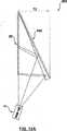
図17Aを参照すると、投影光エンジン14と表示面20と単一の湾曲ミラー702とを含む、本発明による軸外れ投影システム700の一部分が示されている。単一の湾曲ミラー702は、約70mmのサグ(上述のように定義される)を有する非球面ミラーである。図17B、17Cは、それぞれ、歪み図と焦点プロット図を示す。投影システム700は、キーストーン歪みを有し、表示面の最上部を満たさない。キャビネット厚さT3は、結果として得られる5.15のD対D比のために同じ67”対角線表示を持ち、約13インチ厚さである。投影システム700では、湾曲ミラー702は、キーストーン歪みを修正し、画像に表示面20を満たさせるために十分な拡大率を付加する。結果として得られる歪みは約3%である。これは、更なる最適化と画像処理ユニット12の使用とによって改善され得る。更に補正レンズは使用されておらず、僅かな焦点ぼけは投影光エンジン14の投影レンズを約0.8度傾けることによって除去されている。図17B〜17Cに関して、電子的修正は使用されなかった。 Referring to FIG. 17A, a portion of an off-
図16A、17Aの投影システムでは、湾曲ミラー602、702はキーストーン歪みに起因する垂直方向の拡大を修正するために垂直方向の凹面をなお必要としている。しかしながら、この場合、湾曲ミラー602、702は表示面の最上部よりも底部により多く存在する水平方向の圧縮を修正するために、単に水平方向の凸面を必要とする。この場合、投影レンズは表示面の最上部に、所望のものに等しいかそれより僅かに小さい水平方向の画像サイズを生成するように設計されているので、湾曲ミラー602、702の最上部における水平方向のミラー曲率は、単に僅かに凸面であることを必要とする。これに対応して、表示面の底部では、キーストーン歪みは所望のもよりも遥かに小さい水平方向の画像サイズという結果になるので、水平方向のミラー曲率は、より大きな拡大率を与えるためにより強い凸面であることが必要であろう。それにもかかわらず湾曲ミラー602、702はなお、非球面ミラー39と同じ機能を実行し、同じ基本形を持ち、したがって回転非対称である。 In the projection system of FIGS. 16A and 17A, the
補正レンズ49は、個別レンズであるか複合レンズの一部であるかにかかわらず、小形または大形の非球面の回転非対称なミラーと共に使用されるかどうかにかかわらず、同じ機能を実行する。したがって補正レンズ49は、いずれの場合にも同じ基本形状を有する。一般に、補正レンズ49の形状は、補正レンズ49が非球面ミラーに行く光ビームを適当に形作ろうと(すなわちビーム拡大を減らし、それによってスポットサイズを縮小しようと)試みているので、湾曲非球面ミラーの形状をたどる。一般に軸外れ幾何学形状によって、非球面ミラーの最上部と底部との間には、したがって補正レンズには著しい非対称性が存在する。 The
図15〜17のシステムは、f:5で12.3mm焦点距離のレンズと18mm対角線のマイクロディスプレイとを有する8要素投影レンズを備えた投影光エンジンを使用して設計された。このマイクロディスプレイは、1280×720ピクセルのサイズに関して12.27ミクロンの、あるいは1920×1080ピクセルのサイズに関して8.17ミクロンのピクセルピッチを有する。この投影光エンジンは、32.8度の投影射出円錐角を有する。ここに示すその他のシステムは、f:2.8で18.7mm焦点距離のレンズと0・9インチのマイクロディスプレイとを有する8要素投影レンズを備えた投影光エンジンを使用して設計された。この投影光エンジンは、31.7度の投影射出円錐角を有する。しかしながら本発明では他のタイプの投影光エンジンも使用可能であろう。更にここに示された投影システムの側面図は、一定の縮小率で描かれている。これらの投影システムは、例示目的のために図示されており、本発明を限定することは意図されていない。 The system of FIGS. 15-17 was designed using a projection light engine with an 8-element projection lens with a 12.3 mm focal length lens at f: 5 and an 18 mm diagonal microdisplay. The microdisplay has a pixel pitch of 12.27 microns for a size of 1280 × 720 pixels or 8.17 microns for a size of 1920 × 1080 pixels. This projection light engine has a projected exit cone angle of 32.8 degrees. The other system shown here was designed using a projection light engine with an 8 element projection lens with an f: 2.8, 18.7 mm focal length lens and a 0.9 inch microdisplay. This projection light engine has a projected exit cone angle of 31.7 degrees. However, other types of projection light engines could be used with the present invention. Further, the side view of the projection system shown here is drawn with a constant reduction. These projection systems are shown for illustrative purposes and are not intended to limit the invention.
背面投影システムもまた常に、表示面(すなわちスクリーン)からその前にいる観客に向かって水平に現れるビームに投影画像からの光を方向付けする手段を含む。フレネルレンズは点光源から(すなわち投影機25内から)投射される大束の光をコリメートする軽量で比較的低価格の手段であるので、典型的にはフレネルレンズを含んだスクリーンアセンブリが使用される。更に、光の空間分布は、フレネルレンズの中心部分に有利に働く傾向がある。フレネルレンズが投影システム10内で有利に使用されるために、フレネルレンズの焦点距離は、点光源(特に光変調マイクロディスプレイ装置の表面)からの距離と一致するべきである。フレネルレンズは、表示面20の背面に、ある角度で到達するほぼ完全な光学画像を搬送する光線を回転させコリメートするために使用される。光学画像を形成する光線は、表示面上の光線の位置によって異なる角度でフレネルレンズに当たり、またフレネルレンズは、スクリーンに垂直な射出角で光線を送出するために適当な角度(水平方向と同様垂直方向にも)を介して光線を回転させなくてはならない。前述のように、フレネルレンズの中心は、表示面の中心から下方にかなりオフセットされるであろうが、このオフセットの度合いは投影システムのD対D比(すなわち使用される軸外れ幾何学構成の量)に依存する。 A rear projection system also always includes means for directing light from the projected image to a beam that appears horizontally from the display surface (ie, the screen) toward the audience in front of it. Since a Fresnel lens is a lightweight and relatively inexpensive means of collimating a large bundle of light projected from a point light source (ie, from within the projector 25), a screen assembly that includes a Fresnel lens is typically used. . Furthermore, the spatial distribution of light tends to favor the central part of the Fresnel lens. In order for a Fresnel lens to be used advantageously in the
代替の構成では、種々の実施形態における非球面湾曲ミラーは、反射性フレネルミラーであり得る。フレネルミラーは、通常のミラーの湾曲表面を薄い軽量のプラスチックシートに成形された一連の同心円の溝で置き換える。これらの溝は、元の厚い湾曲ミラー表面に極めて近い近似で平行光線を反射する、断面で見たとき小さなプリズムのような個々の反射面として機能する。フレネルミラーは、非球面湾曲ミラーの曲率を複製するために型に等ピッチ円形溝を切り、この型からフレネル構造を製造し、それからそれに前面ミラー(FSM)仕上げを与えるためにこの構造体の表面を金属被覆することによって作ることができる。このフレネル非球面ミラーは、湾曲ミラーのサグを除去することによって更に1〜2インチだけ投影システムのキャビネット奥行きを減らすことができる。一例では60”対角線×8”厚さのシステムにおいて湾曲ミラーの代わりにフレネルミラーを使用することによって1.5”の厚さの節約が実現でき、おそらく9:1のD対D比(すなわち6.5”奥行きで60”対角線)が達成可能であり得る。これは、フレネルミラーが対称ミラー設計から作られなくてはならず、また厚さの僅かな減少が投射比の僅かな変化を意味するので些細な代用ではない。しかしながら、キャビネット厚さの削減は、フレネルミラー解決策を発展させるための動機付けである。フレネル非球面ミラーは、それが置き換える湾曲ミラーと同じサイズであるが、それは遥かに薄い。フレネルミラーの小さな反射溝が非球面非対称湾曲ミラーの表面曲率と同様な効果を与えるので、フレネルミラーはまた、非球面非対称湾曲ミラーが行うのと丁度と同様にキーストーン歪みを減少させる。しかしながら、キーストーン歪みを減らす際のフレネルミラーの性能は、対称フレネルミラーに関する非球面非対称湾曲ミラーの性能ほどは良好でない可能性がある(この場合、画像処理ユニットが更なる歪み修正を与える必要がある)。 In an alternative configuration, the aspheric curved mirror in various embodiments may be a reflective Fresnel mirror. Fresnel mirrors replace the curved surface of a regular mirror with a series of concentric grooves formed into a thin lightweight plastic sheet. These grooves act as individual reflective surfaces like small prisms when viewed in cross-section that reflect parallel rays in an approximation very close to the original thick curved mirror surface. The Fresnel mirror cuts equal pitch circular grooves in the mold to replicate the curvature of the aspheric curved mirror, manufactures the Fresnel structure from this mold, and then the surface of this structure to give it a front mirror (FSM) finish Can be made by metal coating. This Fresnel aspherical mirror can further reduce the cabinet depth of the projection system by 1-2 inches by removing the sag of the curved mirror. In one example, by using a Fresnel mirror instead of a curved mirror in a 60 "
一例として、フレネルミラーは、各半径で連続した最大5カットを取ることで溝を切る天然ダイアモンド工具によって、0.1mm溝ピッチを持つことができる。本技術に精通する人々に知られているように、冷却目的と機械加工された材料を除去するために、切削領域を溢れ流れるように使用される専用の液体を用いて、これらの工具は固有の先端含有角度で特別にカットされ、型は黄銅で作られる。フレネル非球面ミラーは、好ましくはそれが代わりに使われる湾曲した回転非対称のミラーの性能を複製するために非対称である。しかし、フレネル型構造体は旋盤で機械加工されるので、現在の製造上の制約は、フレネル型構造体に回転的対称性を課している。対称フレネルミラーの使用は、投影レンズ設計と画像処理ユニット12とが歪み修正と焦点スポット縮小とにより多くの責任を負わなくてはならないことを意味する。 As an example, a Fresnel mirror can have a 0.1 mm groove pitch with a natural diamond tool that cuts the groove by taking up to 5 consecutive cuts at each radius. As known to those skilled in the art, these tools are unique with dedicated liquids used to overflow the cutting area to cool and remove machined material. Is specially cut at the tip containing angle and the mold is made of brass. A Fresnel aspherical mirror is preferably asymmetrical to replicate the performance of a curved rotationally asymmetrical mirror where it is used instead. However, since Fresnel structures are machined on a lathe, current manufacturing constraints impose rotational symmetry on the Fresnel structures. The use of a symmetric Fresnel mirror means that the projection lens design and
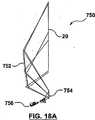
さて図18Aを参照すると、非球面湾曲ミラーの代わりにフレネルミラー752が使用される本発明による投影システム750のもう一つの実施形態が示されている。投影システム750は、平坦なまたは湾曲されたものであり得るミラー754と、投影光エンジン756と、表示面20と、画像処理ユニット(図示せず)とを更に含む。フレネルミラー752のための型は、旋盤で機械加工されるように設計されるので、すなわちフレネルミラーは回転的に対称な非球面ミラーを置き換えるように設計されるので、現在の技術によって製作され得る。型からプラスチックフィルムを製造するために従来の紫外線硬化ポリマー技術が使用でき、またこのプラスチックフィルムは非球面ミラーの光学特性を表す溝を持っている。このフィルムは、剛性の基板上に取り付けられる必要があるであろう(これは良く知られた手法で、例えばガラスに接着され得るであろう)。ミラー表面を得るために、本技術に精通する人々に一般に知られた、フィルムの溝側に反射性の表面を堆積する方法が必要とされる。いったん完全なフレネルミラーが製造されると、フレネルミラー752を与えるために完全なフレネルミラーの中心から四辺形のセグメントが切り出される。この四辺形セグメントは、ミラー752として使用される。図18Bは、完全なフレネルミラーから切り出された同等の四辺形フレネルミラーセグメント752の下に在る、元の湾曲ミラーセグメントの形状の3次元表現を示す。 Referring now to FIG. 18A, there is shown another embodiment of a
さて図18Cを参照すると、補正レンズが使用されず、投影光エンジン756が補正レンズ機能を持つように設計されていないときの投影システム750の性能を示す歪み・プロットが示されている。フレネルミラー752は、本発明の非球面で回転非対称な湾曲ミラーの非対称性を持たないので、キーストーン歪みを効果的に修正できないことは留意されるべきである。しかしながら補正レンズ(そのプロファイルは図18Dに示されている)の追加は、図18Eに示すように歪み・プロットに大きな違いを生じさせる。この場合、補正レンズは(旋盤で機械加工されるよりもむしろ成形され得るので)対称であることに限定されず、またスポット焦点ぼけを減らす際に、より大きな役割を演じなくてはならない。図18Eに示す歪み・プロットは、ディジタル画像処理を使用して1%未満の許容可能なレベルにまで改善され得る。この特定の例では、対応する非球面、対称ミラーセグメントのサグは、45mmであり、3mm厚さのフレネルミラー752を代用することによってキャビネット奥行きは42mmだけ削減される。 Referring now to FIG. 18C, a distortion plot showing the performance of the
図18Fは、フレネルミラー752と共に使用され得る注文製の投影レンズの上面図を示す。投影レンズ760は、レンズ要素762の非球面非対称表面が図18Dに示すレンズプロファイルを持つように第2のレンズ要素762が変えられていることを除いて、図21A〜Bに示す投影レンズと同じである。同様に図18Gは、投影レンズ760の側立面図を示す。図21の投影レンズと同様に投影レンズ760もまた、その設計においてシフト・傾斜手法を使用している。レンズ要素762は、非球面で回転的に対称なフレネルミラーを取り扱わなくてはならない補正レンズの機能を組み込んでいる。補正レンズ表面は、非球面で非対称であり、レンズ要素762の右側の表面である。補正レンズ表面の主要な目的は、レンズ表面がキーストーン歪みをある程度修正するであろうが、焦点ぼけを修正することである。 FIG. 18F shows a top view of a custom projection lens that can be used with the
前述のように投影光エンジンにおける投影レンズの傾斜とシフトは、非球面ミラーによって導入される歪みを修正するために使用され得る。特に投影レンズに関するマイクロディスプレイ装置のレンズシフトまたはシフトは、キーストーン歪みを減らすために本発明の軸外れ投影システムのどれにでも付加され得る。レンズシフトは、まさに、軸外れ投影から結果的に生じるキーストーン歪みを修正する際のもう一つの手法であり、したがって改善されたD対D比を得ることができるもう一つの方法であることは理解されるべきである。 As mentioned above, the tilt and shift of the projection lens in the projection light engine can be used to correct the distortion introduced by the aspherical mirror. A lens shift or shift of the micro display device, particularly with respect to the projection lens, can be added to any of the off-axis projection systems of the present invention to reduce keystone distortion. Lens shift is just another way of correcting the keystone distortion that results from off-axis projection, and is therefore another way that an improved D to D ratio can be obtained. Should be understood.
図18に関して種々のコンポーネントのための例示的寸法が今、与えられるであろう。ミラー754に関しては、傾き角は−19度であり、投影レンズにおける最後のレンズ面からの距離は65.087736mm(中心光線)であり、mm単位での隅のX、Y座標は(68.766592、92.704316)、(51.292765、10.947695)、(−51.297133、10.949841)、(−68.765149、92.709893)である。フレネルミラー752に関しては、ミラーサグは46.34mmであり、傾き角は+19度であり、ミラー754からの距離は353.0113mm(中心光線)であり、mm単位での隅のX、Y座標は(333.965543、464.941499)、(252.931401、74.623281)、(−252.963970、74.640022)、(−333.957131、464.974787)である。表示面20に関しては、傾き角は−19度であり、ミラー752からの距離は539.7357mm(中心光線)であり、サイズは、1524mm対角線で1326mm幅×747mm高さである。 Exemplary dimensions for the various components with respect to FIG. 18 will now be given. For the
図19Aを参照すると、図19Bに示すような27%キーストーン歪みを生成する従来技術の30度軸外れ投影システム780が示されている。投影システム780は、レンズシフトを使用しない。図19Cを参照すると、マイクロディスプレイ/TIRプリズムアセンブリ802を通る光軸の中心線と投影レンズ804自身の光軸の中心線と間にオフセット/シフトが存在することを意味するオフセットまたはシフトを使用する、投影光エンジン800のための従来技術の投影レンズ配置が示されている。この例では、もし軸上投影システムで投影光エンジン800が使用されれば、このシフトは図19Bの27%キーストーン歪みを生成するために十分な大きさである。図19Dを参照すると、投影光エンジン800を利用する30度軸外れの従来技術の投影システム820が示されている。この配置では投影光エンジン800のシフトは、キーストーン歪みを除去するために十分な大きさである(図19E参照)。図19A〜Eのいずれも本発明のコンポーネントを示していないが、図19C〜Dに示す従来技術の手法は、減少したキャビネット奥行きに十分な画像品質を与えるのを助けるために、本発明の実施形態のいずれにも付加することができる。 Referring to FIG. 19A, a
投影レンズのシフトは、投影レンズ804の下半分の大部分が使用され、光線が上半分の一部分を通らないので投影レンズ804の上半分の一部が使用されないようにする。しかしながら、球面の投影レンズの外周部は中心部より多くの収差を持つので、投影レンズは、より多くの近軸光線を使用できることの代わりに投影レンズのコストを僅かに増加させるシフト/オフセットが使用されない投影レンズより大きな直径を持つように設計されなくてはならない。もし投影システムの軸外れ角が27%より大きな歪みが存在するほど大きければ、シフトによって修正されない数パーセントのある過剰な歪みが存在するであろう。この過剰な歪みは、画像処理ユニット12または湾曲ミラーまたは両者の組合せによって処理され得る。代替として、もし投影システムの軸外れ幾何学構成が27%未満の歪みが存在するほど低い角度を持つならば、投影レンズ800は過剰修正し、反対符号のある程度の歪みが存在するであろう(すなわち表示面上で画像の底部は画像の最上部より大きい)し、またそれは画像処理ユニットによって、またはミラープロファイルの変更によって修正され得る。 The projection lens shift prevents most of the lower half of the projection lens 804 from being used and a portion of the upper half of the projection lens 804 from being used because light rays do not pass through a portion of the upper half. However, because the outer periphery of a spherical projection lens has more aberration than the center, the projection lens uses a shift / offset that slightly increases the cost of the projection lens instead of using more paraxial rays It must be designed to have a larger diameter than the projection lens that is not. If the off-axis angle of the projection system is so great that there is distortion greater than 27%, there will be some excess distortion that is not corrected by the shift. This excessive distortion can be handled by the
27%という値が例として与えられており、また投影レンズ800におけるシフトの他の量は、他の量の歪みを修正するために使用され得る。しかしながら適用され得るシフトは、より大きなシフトが適用されると投影レンズの入射瞳におけるカバーレッジ(包括域)はシフトされたマイクロディスプレイを包含する円をカバーするように十分に大きくなければならず、またレンズはこの画像を表示面に投射するために十分に広角設計でなくてはならないので、高価な設計という結果を招く可能性がある。投影画像が歪みなしに、また卓上の表面からの干渉なしに僅かに軸外れ上向きに投影されるように、卓上設置型前面投影機では一般に少量のシフトが使用されることが留意されるべきである。 A value of 27% is given as an example, and other amounts of shift in the
レンズシフトは、投影エンジン設計を複雑にするが、それが使用されるときそれは効果的であり得る。レンズシフトに密接に関係しているのはレンズ傾斜である。最新の投影光エンジンがこれらの手法の両者を使用することによって利益を得られることは、本技術に精通する人々によって知られている。しかしながら、どちらも単独で適用され得る。レンズ傾斜は、典型的には傾いた焦点面に起因する焦点問題を修正するために使用される。今までに示した例では、傾いた焦点面は存在していない(すなわちマイクロディスプレイと表示面は平行である)。しかしながらレンズシフトが使用されるとき、レンズシフトに起因する画像のオフセットが存在する(すなわちもし50%オフセットが使用されれば、画像の底部は投影レンズの中心に近くなるであろう)。如何なるレンズによって生成された画像でも湾曲像面を持つので、表示面に投影される画像の最上部は表示面に投影される画像の底部よりも近くに焦点を結ぶ。マイクロディスプレイの面とレンズの面と表示面とがすべて同じラインに沿って交差する構成は、キーストーン歪みを減少させるであろう。これは、前面投影システム900に関する図20Bに模式的に示されたシャインプフルーク(Scheimpflug)の原理として知られている。スポット焦点ぼけと戦うために、投影レンズは「像面湾曲」の効果を減らすように傾けられ得る。代替として、表示面は内側に傾けられ得るであろうが、投影エンジンを僅か外側に傾けることはより容易である。 Lens shift complicates the projection engine design, but it can be effective when it is used. Closely related to lens shift is lens tilt. It is known by those skilled in the art that modern projection light engines can benefit from using both of these approaches. However, either can be applied alone. Lens tilt is typically used to correct focus problems due to tilted focal planes. In the examples shown so far, there is no tilted focal plane (ie the microdisplay and the display plane are parallel). However, when lens shift is used, there is an image offset due to lens shift (ie, if a 50% offset is used, the bottom of the image will be closer to the center of the projection lens). Since an image generated by any lens has a curved image plane, the top of the image projected onto the display surface is focused closer to the bottom of the image projected onto the display surface. A configuration where the surface of the microdisplay, the surface of the lens and the display surface all intersect along the same line will reduce keystone distortion. This is known as the Scheimpflug principle schematically illustrated in FIG. 20B for the
図20Aを参照すると、投影レンズ902の軸に傾きが存在する従来技術の投影光エンジン900が示されている。この傾きは、キャビネット奥行きを減らしながら像面湾曲スポット焦点ぼけの効果を減らしてシステム性能を改善するために、本発明の投影システムのどれにでも付け加えることができる。この傾きは、マイクロディスプレイ904の画像表面の平面と投影レンズ902の開口入口面の平面との間のものである。この例では傾きは、2、3度に達し、典型的には投影光エンジンにシフトが存在するかどうかとそのシフトの大きさとに依存して、ほぼ1〜2度程度である。如何なる物理的レンズからも現れる球面の波面は、焦点距離の半径の球面に沿って存在する最もよく焦点の合った像点という結果を生じる。Scheimpflugの原理は、もし画像平面とレンズ平面と表示面のすべてが同じラインに沿って交差すれば焦点スポットは最小にされるであろうと述べている。 Referring to FIG. 20A, a prior art projection
図20Bを参照すると、内蔵マイクロディスプレイ傾斜を有する投影光エンジン900が、Scheimpflug条件を満たす構成で示されている。この図に示された「ベストフォーカス(最良焦点、最適焦点)の平面」は、最もよく焦点の合った点が球面に沿って存在するので、実際にベストフォーカスの平面である。この平面は、投影画像の湾曲像面を横切るように示されている。表示面は、表示面の平面と投影レンズの主軸に垂直な平面との間の角度を機械的に減らすことによってこの平面と一致するように動かされなくてはならない。非球面ミラーなどといった投影システムのその他のコンポーネントは、明確さのために図示されていないが、それらが存在していることは明らかである。最良の焦点は常に弧に沿っているので、平面スクリーンでは焦点問題が常に存在するであろう。本発明の軸外れ投影システムでは、焦点問題を軽減するために内蔵の傾きを有する投影光エンジン900が使用され得る。もしベストフォーカスの平面(ベストフォーカスの球形波面に最もよく合うように重ね合わされる)と一致するように表示面が数度傾けられたとすれば、スポットサイズは改善されるであろう。概念的には、マイクロディスプレイ904に対して投影レンズ902を後方に傾け、それからScheimpflugの原理に合うように投影光エンジンを数度前方に傾けることは、より容易である。機械的には、これはレンズマウントの慎重な設計と、正確に傾けられた鏡胴および/または軸外れ機械加工および/または特殊なシム(楔)/座金などの使用とによって実現されなくてはならない。傾けられた投影レンズ900は、本発明の投影システムのどれにでも使用できる。この考えはまた、前面および背面投影システムの両者に適用可能である。 Referring to FIG. 20B, a
既製の投影レンズを使用して、投影レンズがそのために設計された、より小さなマイクロディスプレイを有する光エンジンで使用されるレンズを傾けるか、またはシフトする(すなわちオフセットする)ことは可能である。上述のように、何らかの機械的変更は実施されることが必要であろうことは無論である。投影光エンジンがレンズシフトもレンズ傾斜も使用しない、またはレンズシフトだけを使用する、またはレンズ傾斜だけを使用する、またはレンズシフトとレンズ傾斜両方の組合せを使用する本発明の実施形態のどれにでも投影光エンジンが使用され得ることは理解されるべきである。例えば特定の光変調器のために設計された既製の投影レンズは、シフトと傾斜とを適用することによって異なる、より小形の光変調器での使用のために修正され得る。例えば本発明者らは、1.2”対角線の光変調器用に設計された商用レンズを、0.8”対角線の光変調器での使用のために、50%だけシフトし、1度の何分の一だけこのレンズを傾けた。50%のシフトは、マイクロレンズの最上部エッジが投影レンズの中心にまでシフトされて投影画像の大部分がレンズの上半分から投射されるようにすることを意味する。この場合、画像品質は補正レンズが必要でないほど十分に良好であり、したがって注文の投影レンズ設計の費用が節約された。しかしながらこの設計は、0.8”マイクロディスプレイが第一に軸外れ構成のために必要なシフトと傾斜とに適応するために、第二に異なる光エンジン用に設計された投影レンズの取り付けのために、投影光エンジンの変更を必要としたであろう。その結果は、0.8”光変調マイクロディスプレイを使用する60インチ対角線と8インチキャビネット奥行きとを有する背面投影軸外れシステムである。これは、より大きな(おそらく、より高価な)1.2”光変調マイクロディスプレイを使用する60インチ対角線と20インチキャビネット奥行きとを有する通常の投影システム用に設計された投影レンズを使用することによって達成された。 Using off-the-shelf projection lenses, it is possible to tilt or shift (ie offset) the lenses used in light engines with smaller microdisplays for which the projection lenses are designed. Of course, as mentioned above, some mechanical changes will need to be implemented. Any of the embodiments of the invention in which the projection light engine uses no lens shift or lens tilt, uses only lens shift, uses only lens tilt, or uses a combination of both lens shift and lens tilt. It should be understood that a projection light engine can be used. For example, off-the-shelf projection lenses designed for a particular light modulator can be modified for use with smaller light modulators that differ by applying shift and tilt. For example, the inventors have shifted a commercial lens designed for a 1.2 "diagonal light modulator by 50% for use with a 0.8" diagonal light modulator, what is once Tilt this lens by a fraction. A 50% shift means that the top edge of the microlens is shifted to the center of the projection lens so that the majority of the projected image is projected from the upper half of the lens. In this case, the image quality was good enough that no correction lens was required, thus saving the cost of a custom projection lens design. However, this design is second for the mounting of projection lenses designed for different light engines, secondly to accommodate the shift and tilt required for 0.8 "microdisplays, primarily for off-axis configurations. The result was a rear projection off-axis system with a 60 inch diagonal and an 8 inch cabinet depth using a 0.8 "light modulated microdisplay. This is by using a projection lens designed for a normal projection system with a 60 inch diagonal and a 20 inch cabinet depth using a larger (probably more expensive) 1.2 "light modulation microdisplay. Achieved.
前述のように、光エンジンに搭載される注文設計の投影レンズは、補正レンズ49をなくすために、本発明の種々の実施形態において使用可能である。注文製の投影光エンジンは、その投影レンズハウジング内に補正レンズ49を含むことができる。この場合、投影光エンジンのハウジングはより長くなり、投影光エンジン全体はより高価になる。代替として注文製の投影光エンジンは、湾曲非球面ミラーによって導入された歪みをある程度または完全に修正するために非球面で回転非対称の曲率を有する注文製のレンズ要素を含むことができる。この場合、注文製の投影光エンジンはよりコンパクトになる。 As mentioned above, a custom designed projection lens mounted on the light engine can be used in various embodiments of the present invention to eliminate the
非球面的に湾曲した回転非対称のミラーと共に使用できる注文製のレンズの一例が図21A〜21Cに示されている。この設計はまた非球面的に湾曲した回転的に対称なミラー(このミラーの代わりにフレネルミラーを使用するために)とも同様に(図18F〜G参照)機能するように使用されたが、これらのレンズ要素のうちの一つレンズ要素の表面プロファイルは変更されなくてはならなかった。さて図21A、21Bを参照すると、注文製の8要素投影レンズ950の上面および側面の断面図が示されている。投影レンズ950の要素は、右から始めて凸凹面を有する第1の要素952と、非対称非球形凹面を有する第2の要素954と、ダブレットである第3の要素956と、両凸レンズである第4の要素958と、ダブレットである第5の要素960と、ダブレットである第6の要素962と、両凸レンズである第7の要素964と、平凸レンズである第8の要素966とである。レンズシフトとレンズ傾斜の両方が使用されており、図21Bはシフト(オフセット)を極めて明瞭に示しているが、傾斜は少し見えにくい。この傾斜は、レンズ要素966から始まっている。 An example of a custom lens that can be used with an aspherically curved rotationally asymmetric mirror is shown in FIGS. This design was also used to work with aspherically curved rotationally symmetric mirrors (to use a Fresnel mirror instead of this mirror) as well (see FIGS. 18F-G). The surface profile of one of the lens elements had to be changed. Referring now to FIGS. 21A and 21B, top and side cross-sectional views of a custom 8-
図21Cは、注文製の投影レンズ950の第2のレンズ要素954に組み込まれた非球面で回転非対称の面のプロファイルを示す。図21Bの側面図ではこの表面とレンズ要素952の第2の表面との間に何らかの干渉が存在するように見えるが、これは、レンズの底部が使用されず(シフトのために)また削り落とされ得るので、実際には発生しないであろう。投影レンズ950は、焦点の修正を持っており、また補正レンズを使用する湾曲ミラーシステムのどれにおいても使用され得る。図18の投影レンズは、対称な表面を使用しなくてはならないという制約のためにフレネルミラーによって完全には処理できないキーストーン歪みに関する修正を行う。 FIG. 21C shows the profile of an aspheric, rotationally asymmetric surface incorporated into the
図22を参照すると、本発明の画像処理ユニット1000の例示的実施形態のブロック図が示されている。画像処理ユニット1000は、如何なる残留キーストーン歪みおよびその他の空間歪みも修正するために、本発明の如何なる実施形態の光学系にも統合され得る。画像処理ユニット1000は、図示のように接続された画像捕捉(撮像)モジュール1002と、画像プロセッサモジュール1004と、表示コントローラモジュール1006と、コントローラ1008と、メモリインタフェースモジュール1010とを含む。画像捕捉モジュール1002と画像プロセッサモジュール1004と表示コントローラモジュール1006はすべて、データとパラメータの記憶と検索のためにメモリインタフェースモジュール1010に接続される。 Referring to FIG. 22, a block diagram of an exemplary embodiment of the
未処理の画像データは、画像捕捉モジュール1002によって検索され、そこでディジタル化される。ディジタル化された画像データはそれから、輝度修正ステージ1012と画像ワーピングステージ1014とを経由してディジタル画像処理とキーストーン修正とのために画像プロセッサモジュール1004に送られる。画像プロセッサモジュール1004は、コントローラモジュール1008から歪みパラメータを取得し、ディジタル画像データを歪み補正するために、画像ワーピングステージ1014を経由して画像変換を生成する。この歪み補正されたディジタル画像データはそれから、表示コントローラモジュール1006に渡され、このモジュール1006は、歪み補正された画像データに基づいて光を変調し、光エンジンからこの光を投影する。この光が全光学系を通って投影システムの表示面に伝播するとき、全光学系に起因する歪みは画像内に存在する補正的歪みを打ち消し、結果として得られる表示は、実質的に歪みなしになる。 The raw image data is retrieved by the
輝度修正ステージ1012は、明るさまたは輝度の不均一性を修正するために使用される。したがって輝度修正ステージ1012は、入力画像データを受け取って、輝度調整された画像データを生成する。輝度修正ステージ1012は、表示画像の点またはセクションの強度が走行距離の二乗に逆比例して変化し、これが表示画像内の明るさのバラツキにつながるので、所定のピクセル位置における色空間のピクセル輝度を修正するために予め決められたマップを適用する。画像マップのための種々の方程式が使用され得る(線形の例は、前に与えられた)。 The
画像ワーピングステージ1014は、投影レンズ5と補正レンズ49と非球面ミラー39と軸外れ投影幾何学構成と設置の位置合わせ不良とに起因する残留未修正歪み組合せを修正するために使用される。画像ワーピングステージ1014は、投影光エンジン14とその関連する反射(ミラー)光学系(図示せず)とによって導入された幾何学的歪み(図示せず)の逆である幾何学変換にしたがって入力画像を歪み補正するために、入力画像に変換を適用する(その一例は図9aに示されている)。したがって画像ワーピングステージ1014は、輝度調整された画像データを受け取って歪み補正された画像データを生成する。画像ワーピングステージ1014は、如何なる関連歪みも投影光エンジンのレンズの光学特性を整合させることよりも、むしろ事前ワーピングによって除去されるので、光学レンズのより柔軟な選択を可能にする。画像ワーピングステージ1014の特定の実施形態は、引例によってここ組み込まれているGreggainらの米国特許第5,594,676号によって与えられている。
輝度修正ステージ1012と画像ワーピングステージ1014は、白色光のすべての成分波長に等しく作用できる。しかし、このステージはまた、R、G、Bの波長にしたがって異なって作用し得る。これは結果として、更なる利益、すなわち横の色シフトの修正と、ある一定の色収差の修正とをもたらす。もし色収差と横の色シフトとが画像処理ユニット1000によって修正されることができれば、投影レンズ設計は、対応する製造コストの節約と共に大いに単純化され得る。しかしながら、画像処理ユニットの各ステージに1個の代わりに3個の同じ画像処理エンジンを必要とすることにより、エレクトロニクス(電子的手段)のコストは上昇するであろう。 The
輝度修正ステージ1012と画像ワーピングステージ1014は、ソフトウエアモジュールによって、またはディジタル信号プロセッサといった専用の処理回路によって、または特定用途向け集積回路によって実現可能である。データ経路におけるこれらのステージの順序はまた、交換可能である。 The
使用時に歪みパラメータの全空間をカバーする歪みパラメータの値の包括的範囲は、最初に画像処理ユニット1000に関して取得される。歪みパラメータに関する値は、ユーザインタフェースを介して取得でき、投影システムの種々の幾何学的光学的構成にしたがってオフラインで決定され得る。歪みパラメータに関する各1セットの値のために、画像ワーピングステージ1014によって適用される歪み補正変換をパラメータ化する変換が取得される。それから、歪みパラメータに関する可能な値の全空間をカバーする歪みマップデータベースが用意される。このデータベースへのアクセスは、製造時、出荷後などに発生し得る較正が投影システムのために必要とされるたびごとに必要となる。それから、投影システムの最終的歪みパラメータに対応する歪みマップデータベースから、単一の歪み変換が抽出される(すなわち、いったん投影システムが設置されると、光学的位置合わせは手付かずであるので、あまり大きくは変わらないであろう)。最終歪みマップは、ディジタル化された入力画像データを幾何学的に調整する(すなわち歪み補正する)ために画像ワーピングステージ1014によって使用される。 A comprehensive range of distortion parameter values covering the entire space of distortion parameters in use is first obtained for the
一般に本発明による投影システムの実施形態に関してここに示された種々の性能図は、画像処理ユニット12によって実行される修正を示していない。しかしながら、電子的修正が画像処理ユニット12によって行われるとき、歪みが1%以下の値にまで大幅に削減されることは理解されるべきである。 In general, the various performance diagrams shown herein with respect to an embodiment of the projection system according to the present invention do not show the modifications performed by the
本発明者らは、レンズ傾斜と、レンズシフトと、おそらくは投影レンズ光学系における一つ以上の非球面要素と、少なくとも一つの湾曲非球面ミラーと、電子的歪み修正との種々の組合せを使用する投影システムにおいて許容可能な画像品質を保持しながらD対D比が改善され得ることを見出している。画像処理ユニットによって与えられる電子的歪み修正は、設計の結果、または個別のコンポーネントの偏差に起因する、および/または上記の要素の種々の組合せに関する機械的組立て公差に起因する残留歪みを「チューンアウト(調整)」するために、特別な自由度として使用され得る。 We use various combinations of lens tilt, lens shift, and possibly one or more aspheric elements in the projection lens optics, at least one curved aspheric mirror, and electronic distortion correction. It has been found that the D to D ratio can be improved while maintaining acceptable image quality in the projection system. The electronic distortion correction provided by the image processing unit “tunes out” residual distortion due to design results or individual component deviations and / or due to mechanical assembly tolerances for various combinations of the above elements. (Adjustment) "can be used as a special degree of freedom.
消費者用RPTVにおけるD対D比に関する技術の現状は、約3.2:1である。業務用背面投影システム(消費者用製品よりも3〜5倍高価である)におけるD対D比に関する技術の現状は、約6:1である。本発明の種々の実施形態は、消費者用RPTVが5:1以上のD対D比を達成することを可能にするであろう。例えば単純な非球面投影レンズと画像処理ユニットとを有する大形の湾曲ミラーを使用して5.5:1のD対D比を達成することが可能である。もう一つの例は、マイクロディスプレイのシフトと傾斜とを前のケースに加えて、注文設計のレンズプロファイルを再度最適化することによる7.5:1のD対D比である。消費者用RPTV製品に関する他の例は、a)外付け補正レンズを有する投影レンズに傾斜もシフトも使用しない小形湾曲ミラー軸外れ投影システム(図6に示すシステムに類似の)に関する6というD対D比と、b)外付け補正レンズを有する投影レンズに傾斜もシフトも使用しない大形湾曲ミラー軸外れ投影システム(図16Aに示すシステムに類似の)に関する7.5というD対D比と、c)注文の投影レンズ設計にシフトばかりでなく傾斜も使用する大形湾曲ミラー軸外れ投影システムに関する7.5というD対D比(これは図18Aに示す構成において図18F〜Gに示すレンズを使用することによって達成され得るであろう)と、d)注文の投影レンズ設計においてシフトばかりでなく傾斜も使用する大形フレネルミラー軸外れ投影システムに関する8.5というD対D比(これは図16Aに示す構成において図21A〜Bに示すレンズを使用することによって達成され得るであろう)である。投影光エンジンがキャビネットの厚さ内に納まるためのある一定の最小機械寸法が満たされる限り、すべてのものは直線的に比例するので、スクリーン対角線とキャビネット厚さとに関する詳細が、比率を除いてあまり重要でないことは理解されるべきである。 The current state of the art for D to D ratio in consumer RPTV is about 3.2: 1. The current state of the art for D to D ratio in commercial rear projection systems (3-5 times more expensive than consumer products) is about 6: 1. Various embodiments of the present invention will allow a consumer RPTV to achieve a D to D ratio of 5: 1 or higher. For example, a large curved mirror with a simple aspheric projection lens and an image processing unit can be used to achieve a
しかしながら、これらの手法の使用においては、コストと性能とのトレードオフ関係が存在する。例えばレンズまたはマイクロディスプレイのオフセットの使用は、コストを増加させる大きなレンズ開口を使用することを含む。このトレードオフは、大きなレンズ/マイクロディスプレイ・オフセットはより多くのキーストーン歪み修正を可能にするが、大きなレンズ要素が必要となるので投影レンズのコストは増加する、ということである。更に非球面で回転非対称のレンズ要素が使用されると、射出成形のレンズ要素を作製するために工具コストが増加するのでコストは増加する。更に非球面で回転非対称のミラーを作製するとき、正確に輪郭形成された光学表面を有する前面ミラーを製造するためのコスト上昇が存在する(型加工コストもまた負わなくてはならない可能性がある)。 However, there is a trade-off between cost and performance when using these techniques. For example, the use of lens or microdisplay offsets involves the use of large lens apertures that increase costs. The trade-off is that large lens / microdisplay offsets allow more keystone distortion correction, but the cost of the projection lens increases because larger lens elements are required. In addition, the use of aspheric and rotationally asymmetric lens elements increases the cost as tool costs increase to produce injection molded lens elements. In addition, when making aspheric and rotationally asymmetric mirrors, there is an increased cost to produce front mirrors with precisely contoured optical surfaces (molding costs may also have to be incurred) ).
ここで論じられた種々の実施形態で示されたように、本発明は、ミラーの少なくとも一つが湾曲面を有するか、ミラーの一つが光ビームに対して軸外れ角で配置されるか、あるいはその両者である1個、2個および3個ミラー軸外れ投影システムに適用可能である。すべての場合に、画像が湾曲ミラーによって反射された後に歪みを修正するために、補正レンズまたは注文設計の投影レンズが使用される。更に如何なる残留歪みをも修正するために、画像処理ユニットが必要とされる。更にこの構成への一つ以上の平面ミラーの追加は、垂直高さ対キャビネット奥行きにおける更なるトレードオフが行われることを可能にする。より多数のミラーの使用はまた、投影システムのコンポーネントを配置する際に特別の柔軟性と、キャビネット厚さを削減する能力とを与えるが、不利益は位置合わせにおけるより大きな困難さである。二つの湾曲ミラーを使用することはまた、ミラー製造におけるある単純化の可能性を見込んでいるが、再び位置合わせにおける余分な複雑さが存在する。フレネルミラーの使用は、大きな湾曲ミラーを置き換え、コスト削減ならびにキャビネット厚さとD対D比に更なる改善をもたらす可能性を持っている。 As shown in the various embodiments discussed herein, the present invention provides that at least one of the mirrors has a curved surface, one of the mirrors is disposed at an off-axis angle with respect to the light beam, or The two, one, and three mirror off-axis projection systems can be applied. In all cases, a correction lens or a custom designed projection lens is used to correct the distortion after the image is reflected by the curved mirror. In addition, an image processing unit is required to correct any residual distortion. Furthermore, the addition of one or more plane mirrors to this configuration allows further trade-offs in vertical height vs. cabinet depth to be made. The use of a larger number of mirrors also provides extra flexibility in positioning the components of the projection system and the ability to reduce cabinet thickness, but the disadvantage is greater difficulty in alignment. Using two curved mirrors also allows for some simplification possibilities in mirror manufacture, but again there is extra complexity in alignment. The use of Fresnel mirrors has the potential to replace large curved mirrors, resulting in cost savings and further improvements in cabinet thickness and D to D ratio.
本発明によれば、少なくとも一つの湾曲ミラーと画像処理ユニットとを有する投影システムを設計するための典型的な設計プロセスは、下記のステップを含む。 In accordance with the present invention, an exemplary design process for designing a projection system having at least one curved mirror and an image processing unit includes the following steps.
i)投影システムに関する設計制約を定義するステップ
1)焦点距離、fナンバー(すなわちレンズ直径対焦点距離の比率)などを含む投影レンズ設計といった投影光エンジンのパラメータを定義するステップ、
2)キャビネット奥行きと、ミラーの数(1個、2個、または3個)と、どのミラーが湾曲ミラーであるかと、キャビネット構成(自由直立型、壁掛けユニットなど)と、表示面のサイズなどとを定義するステップ、
ii)ミラーに関する初期構成を定義するステップ
3)投影機光エンジンとミラーとの間の角度と距離とを設定するために少なくとも一つのミラーを使用するステップ(もし一つのミラーが使用されるのであればそれは湾曲ミラーである。もし二つ以上のミラーが使用されるのであればそれらのミラーのうちの一つは平坦でよい)。もしフレネルミラーが大形湾曲ミラーの代わりに使用されるのであれば、
a)光学画像の投影経路をクリアーに保持しながらキーストーン歪みを最小にするために投影光エンジンとミラー(単数または複数)との間の角度と距離とを最適化するステップ(すなわち光学画像に影を投射することを避けるために、投影経路は湾曲ミラー表面と共に変化することに留意すること)、
b)もし投影光エンジンによって許されるならば、歪みとスポットスメア/焦点ぼけと、を最小にするために表示装置に関する投影レンズのシフトと傾斜とを調整する(またはその逆を行う)ステップ(このステップはまたステップ3aで述べた角度と距離とを再最適化することを含む)、
4)適当な光学シミュレータ(Oslo(登録商標)、Zemax(登録商標)などといった)において湾曲ミラーのためにある一定の初期構成と材料と初期寸法とを選択するステップ、
iii)湾曲ミラーの表面形状を最適化し、補正レンズを設計するステップ
5)湾曲ミラーによる歪みを最小にするために最適化誤差関数(平均二乗誤差などといったシミュレータによって与えられる)を設定し、誤差関数を最小化するために湾曲ミラーの表面形状を最適化するステップ、
a)湾曲ミラーの厚さと曲率と傾斜とに関して必要に応じて制約を調整するステップ、
b)必要に応じて制約を再シミュレートして再調整するステップ、
c)光路を衝突に関してチェックするステップ、
d)投影システムに関して許容可能な歪みと焦点ぼけが得られるまでステップ5a〜5cを繰り返すステップ、
6)機械的要件内に補正レンズを抑制しながら最小の焦点スポットサイズを与えて過剰な歪みを防止するために、補正レンズを最適化しながら補正レンズの設計(または注文の投影光エンジン設計内のレンズ表面)のためにステップ4、5を適用するステップ(すなわち補正レンズは、補正レンズの表面プロファイルを画定する数学関数の振動によって引き起こされる人為構造が所望の表面プロファイルに収束するので、その人為構造のゆえにその公称サイズより大きくなるように設計される。公称寸法以外の補正レンズの部分は単純には製造されない)、
7)補正レンズまたは注文製の投影レンズによって導入される如何なる歪みも最小化するように湾曲ミラーを再最適化するステップ(これは、正および/または負の曲率を付加することによって湾曲ミラーのプロファイルを僅かに調整することと、凹面曲率と凸面曲率との間の遷移比率を調整することなどを含む可能性がある)、
8)湾曲ミラーの曲率の変化によって導入される焦点スポットサイズ如何なる劣化も最小にするように補正レンズを再最適化するステップ。i) defining design constraints for the projection system 1) defining projection light engine parameters such as projection lens design including focal length, f-number (ie, ratio of lens diameter to focal length), etc.
2) Cabinet depth, number of mirrors (1, 2, or 3), which mirror is a curved mirror, cabinet configuration (free standing type, wall-mounted unit, etc.), size of display surface, etc. Step to define,
ii) defining an initial configuration for the mirror 3) using at least one mirror to set the angle and distance between the projector light engine and the mirror (if one mirror is used) It is a curved mirror, if two or more mirrors are used, one of them may be flat). If a Fresnel mirror is used instead of a large curved mirror,
a) optimizing the angle and distance between the projection light engine and the mirror (s) to minimize keystone distortion while keeping the optical image projection path clear (ie, to the optical image) Note that the projection path changes with the curved mirror surface to avoid projecting shadows),
b) adjusting the projection lens shift and tilt with respect to the display device (or vice versa) to minimize distortion and spot smear / defocus if allowed by the projection light engine (or vice versa) The step also includes reoptimizing the angles and distances mentioned in step 3a)
4) selecting certain initial configurations, materials and initial dimensions for the curved mirror in a suitable optical simulator (such as Oslo®, Zemax®, etc.);
iii) Optimizing the surface shape of the curved mirror and designing a correction lens 5) Set an optimization error function (given by a simulator such as mean square error) to minimize distortion caused by the curved mirror, and the error function Optimizing the surface shape of the curved mirror, to minimize the
a) adjusting the constraints as needed with respect to the thickness, curvature and tilt of the curved mirror;
b) re-simulating and re-adjusting the constraints as needed;
c) checking the optical path for collisions;
d) repeating steps 5a-5c until acceptable distortion and defocus are obtained for the projection system;
6) Correct lens design (or within a custom projection light engine design) while optimizing the correction lens to give the minimum focal spot size and prevent excessive distortion while keeping the correction lens within mechanical
7) Re-optimizing the curved mirror to minimize any distortion introduced by the correction lens or a custom projection lens (this is the profile of the curved mirror by adding positive and / or negative curvature) And slightly adjusting the transition ratio between the concave curvature and the convex curvature),
8) Re-optimizing the correction lens to minimize any degradation of the focal spot size introduced by the curvature change of the curved mirror.
このプロセスは、極めて迅速に収穫逓減を与え、もし補正レンズと湾曲ミラーとに関して適当な初期プロファイルが選択されれば、解は最適値に迅速に収束するであろう。これらのプロファイルは、3次または5次多項式によって近似され得る。ミラーの表面曲率を設計する際に、バイキュービック・スプライン関数、コサイン関数または類似の数学関数を使用する内挿法が使用できる。これらの近似値を計算するために、Excelスプレッドシートまたはその他任意の適当なコンピュータプログラムが使用可能である。 This process provides diminishing returns very quickly, and if an appropriate initial profile is selected for the correction lens and curved mirror, the solution will converge quickly to an optimal value. These profiles can be approximated by third or fifth order polynomials. In designing the surface curvature of the mirror, interpolation methods using bicubic spline functions, cosine functions or similar mathematical functions can be used. An Excel spreadsheet or any other suitable computer program can be used to calculate these approximations.
投影システム10は、特別に構成された投影要素の使用によって光学画像のほぼ歪みなしの投影を与える。投影システム10は、幾何学的およびその他の光学的歪みを修正する画像処理ユニットによって短い投射距離を達成しながら、固有の歪みを有する一般的短投射距離光学系を組み込んでいる。投影システム10は、許容可能な歪みレベルを有する所望の短い投射比を達成するために、非球面ミラー39と補正レンズ49と電子的修正とを使用する。画像処理ユニット12は、投影光エンジンと光反射アセンブリと投影幾何学構成と組立て位置合わせの3本の回転軸すべてとの組合せ空間歪みに関する修正を実行する。画像処理ユニット12は、キーストーン歪みと樽型/糸巻き型歪みと色の非収束(x、yまたはθ軸におけるマイクロディスプレイの位置合わせ不良による可能性がある)とに取り組むことができる。特に画像処理ユニット12は、任意の拡大縮小(画像の水平垂直両方向の寸法と、異なる領域とにおける)と、すべての可視光の波長に関する直線的な拡大縮小と、幾つかの所望の光のパスバンドの各々に関して等しくまたは特にプログラムされた任意の拡大縮小とを与える。クロミナンスと輝度の不均一性もまた、画像処理ユニット12によって修正され得る。レンズ設計は、通常の球面収差と横の色シフトといったレンズ収差と歪みが電子的修正に従うので、単純化され得る。画像処理ユニット12が如何なる残留歪みをも除去するために役立つので、システム設計はもはや歪みを光学的に最小化するという制約によって限定されない。これはまた、より複雑な光学的手段よりもむしろディジタルに微調整する任意の手段を適用できるという更なる利益を有する。数個のミラー(平面および/または非平面の)および/または投影光エンジンを組み合わせることによって変形版を得ることができる。このシステム設計方法論は、前面投影、背面投影の両構成に適用可能である。
もう一つの代替手段では、キーストーン歪みおよびその他の空間歪みに適応するように形作られた光変調マイクロディスプレイ装置を使用することが可能である。マイクロディスプレイ装置は、投影レンズと一つ以上のミラーとからなる軸外れ光路を変調された光が通るときに、結果的に生じる歪みの一部または全部が修正され、表示面に正しい画像が投影されるという結果が得られるように、適切に形作られた複数のピクセルからなる。もしマイクロディスプレイ装置が伝統的な軸外れシステムのために作られるのであれば、それは伝統的なD対Dシステムにおける平面ミラーと共に使用でき、また、より積極的に指定されたシステムのためには湾曲ミラーと共に使用され得る。利点は、光学系と画像処理とが単純化され得ることである。しかしながらこれは、注文製のマイクロディスプレイ装置の製造コストに関して比較検討する必要がある。このようなマイクロディスプレイ装置を作る際の困難の一つは、ライン構造に極めて小さな形状で「階段(段々)」または「ジャギー(ぎざぎざ)」が現れる可能性があるので、互いに直角に走らないラインを有するフォトリソグラフィー・マスクをエッチングすることである。幸いなことに、これらのマイクロディスプレイを製造するために使用される幾何学構造は、メモリおよび処理装置のために必要とされる幾何学構造ほど小さくなければならないことはほとんどない。 In another alternative, it is possible to use a light modulation microdisplay device shaped to accommodate keystone distortion and other spatial distortions. A microdisplay device corrects some or all of the resulting distortion when modulated light passes through an off-axis optical path consisting of a projection lens and one or more mirrors, and projects the correct image on the display surface. It consists of a number of appropriately shaped pixels so that a result is obtained. If a microdisplay device is made for a traditional off-axis system, it can be used with a plane mirror in a traditional D vs. D system, and curved for a more aggressively specified system Can be used with mirrors. The advantage is that the optics and image processing can be simplified. However, this needs to be compared with respect to the manufacturing cost of the custom microdisplay device. One of the difficulties in making such a micro display device is that lines that do not run at right angles to each other because “steps” or “jaggies” may appear in the line structure in a very small shape. Etching a photolithography mask having Fortunately, the geometry used to fabricate these microdisplays rarely has to be as small as that required for memory and processing equipment.
ここに示された種々の実施形態がコンパクトな前面投影システムにも適用可能であることは留意されるべきである。しかしながら、前面投影システムに関しては表示面にフレネルレンズの必要はない。 It should be noted that the various embodiments shown here are also applicable to compact front projection systems. However, for front projection systems, there is no need for a Fresnel lens on the display surface.
本技術に精通する人々にとって明らかであるように、前述の構造の種々の修正版と適応版は、その範囲が付属の請求項に記載されている本発明から逸脱することなく可能である。 As will be apparent to those skilled in the art, various modifications and adaptations of the foregoing structure are possible without departing from the invention, the scope of which is set forth in the appended claims.
Claims (56)
Translated fromJapanese投影前に2次元の電子的に歪んだ画像データを生成するために、画素の2次元配置を示す前記入力画像データを受け取って前記入力画像データを電子的に歪ませるための画像処理ユニットと、
画素の2次元配置を調整するための手段を有する表示装置を備え、前記画像処理ユニットに連結されると共に前記電子的に歪んだ画像データを受け取るように適応され、前記表示装置に前記電子的に歪んだ画像データに相当する2次元の歪んだ画像を調整し、前記2次元の歪んだ画像を投影して投影画像を生成する投影光エンジンと、
前記投影画像を前記表示面上に導くように適応された前記投影光エンジンに連結され、少なくとも一つの湾曲ミラーを備えた光反射アセンブリと、を含み、
前記電子的な歪みが、前記表示面上の前記投影画像において前記投影光エンジン及び前記光反射アセンブリで引き起こされる歪みを有する光学的幾何学的歪みが実質的に除去されるように作用する
軸外れ投影システム。An off-axis projection system for displaying an image on a display surface based on input image data,
An image processing unitfor receiving the input image dataindicating a two-dimensional arrangement of pixelsand electronically distorting the input image data togenerate two-dimensional electronically distorted image data before projection ;
A display device having means for adjusting a two-dimensional arrangement of pixels, coupled to the image processing unit and adapted to receive the electronically distorted image data; A projection light enginethat adjusts a two-dimensional distorted image corresponding to the distorted image data and projects the two-dimensional distorted image to generate a projectionimage ;
A light reflecting assemblycoupled to the projection light engine adapted to direct the projected image onto the display surface and comprising at least one curved mirror;
The electronic distortion, optical geometric distortionhaving distortion caused by the projection light engine and the optical reflection assembly in the projected image on the display surfaceacts assubstantive removed
Off-axis projection system.
光ビームを発生させるための光発生器と、
前記光発生器の前に配置された前記表示装置と、
前記表示装置の前に配置され、前記投影画像を投影しながら焦点合わせするための投影光学系と、を含む、
請求項1に記載の軸外れ投影システム。The projection light engine comprises:
A light generator for generating a light beam;
Said display device arranged in front of the light generator,
Wherein disposed in front of the displaydevice, includinga projection optical systemfor focusing while projecting the projected image,
Theoff-axis projection system according to claim 1.
前記入力画像データにおけるピクセル輝度を調整して輝度調整された前記入力画像データを生成するための輝度修正ステージと、
輝度調整された入力画像データを受け取って前記2次元の電子的に歪んだ画像データを生成するための、前記輝度修正ステージに接続された画像ワーピングステージと、を含む、
請求項1に記載の軸外れ投影システム。The image processing unit includes:
Luminance modification stagefor generatingthe input image data luminance adjustmentby adjusting pixel brightness in the input image data,
For generating image datadistorted electronically in the two-dimensional receive input image data luminance adjustment,including, an image warping stage connected to the luminance modification stage
Theoff-axis projection system according to claim 1.
前記画像データに応じた光を反射することによりキーストーン歪みが低減されるように形成された湾曲ミラーを少なくとも一つ有し、前記投影光エンジンと表示面との間に配置され、前記投影光エンジンから入射された光を前記表示面に投影するように構成された光反射アセンブリと、を含む軸外れ投影システムであって、 The projection light includes at least one curved mirror formed so as to reduce keystone distortion by reflecting light according to the image data, and is disposed between the projection light engine and a display surface. A light reflecting assembly configured to project light incident from an engine onto the display surface, the off-axis projection system comprising:
前記画像データに応じた光が表示面に入射された際に前記投影光エンジン及び前記光反射アセンブリに起因して生じる前記キーストーン歪みを有さない前記画像が前記表示面に表示される予め定められた入射角未満の入射角で前記光が前記表示面に入射されることにより前記表示面に表示される前記画像に含まれる前記キーストーン歪みを打ち消すために予め定められた歪みを示す歪みデータを予め記憶した記憶手段と、 When the light corresponding to the image data is incident on the display surface, the image without the keystone distortion caused by the projection light engine and the light reflecting assembly is displayed on the display surface. Distortion data indicating a predetermined distortion for canceling the keystone distortion included in the image displayed on the display surface when the light is incident on the display surface at an incident angle smaller than the incident angle. Storage means for storing in advance,
前記画像データとして、前記記憶手段から取得した歪みデータにより示される前記予め定められた歪みを含む前記画像を示す歪み対応画像データを生成する画像データ生成手段と、 Image data generation means for generating distortion corresponding image data indicating the image including the predetermined distortion indicated by the distortion data acquired from the storage means as the image data;
を含む軸外れ投影システム。 Including off-axis projection system.
前記光反射アセンブリは、前記湾曲ミラーで反射された光を前記表示面に投影するように反射する平面状反射面を有する第1の平面ミラーを更に含んで構成された請求項21または請求項22に記載の軸外れ投影システム。 The said light reflection assembly is further comprised including the 1st plane mirror which has a planar reflective surface which reflects the light reflected by the said curved mirror so that it may project on the said display surface. Off-axis projection system as described in.
光ビームを発生させるための光発生器と、 A light generator for generating a light beam;
前記画像データ生成手段によって生成された前記歪み対応画像データに従って前記光発生器によって発生された光ビームを変調する変調手段と、 Modulation means for modulating a light beam generated by the light generator according to the distortion-corresponding image data generated by the image data generation means;
前記変調手段によって変調された前記光ビームの焦点を合わせるための投影光学系と、を含んで構成された請求項21〜請求項31の何れか1項に記載の軸外れ投影システム。 The off-axis projection system according to any one of claims 21 to 31, comprising a projection optical system for focusing the light beam modulated by the modulation means.
前記投影レンズの光軸を、前記キーストーン歪みとスポットサイズとを補正するように、前記表示面の中心からオフセットした請求項32記載の軸外れ投影システム。 The off-axis projection system according to claim 32, wherein the optical axis of the projection lens is offset from the center of the display surface so as to correct the keystone distortion and the spot size.
前記画像データ生成手段は、前記輝度修正手段によって前記ピクセル輝度が調整された前記画像データに対して、前記記憶手段から取得した歪みデータにより示される歪みを付与することにより、前記歪み対応画像データを生成する請求項21〜請求項35の何れか1項に記載の軸外れ投影システム。 The image data generation unit adds the distortion indicated by the distortion data acquired from the storage unit to the image data whose pixel luminance has been adjusted by the luminance correction unit, thereby obtaining the distortion-corresponding image data. The off-axis projection system according to any one of claims 21 to 35, which is generated.
投影前に2次元の電子的に歪んだ画像データを生成するために、画素の2次元配置を示す入力画像データを受け取って前記入力画像データを電子的に歪ませるステップと、
画素の2次元配置を調整するための手段を有する表示装置を備えた投影光エンジンが、前記画像処理ユニットに連結されると共に前記電子的に歪んだ画像データを受け取るように適応され、前記表示装置に前記電子的に歪んだ画像データに相当する2次元の歪んだ画像を調整し、前記2次元の歪んだ画像を投影して投影画像を生成するステップと、
前記投影光エンジンに連結されると共に前記投影画像を前記表示面上に導くように適応され、少なくとも一つの湾曲ミラーを備えた光反射アセンブリで前記投影画像を反射するステップと、を含み、
前記電子的な歪みが、前記表示面上の前記投影画像において前記投影光エンジン及び前記光反射アセンブリで引き起こされる歪みを有する光学的幾何学的歪みが実質的に除去されるように作用する
軸外れ投影方法。An off-axis projection method for displaying an image on a display surface of an off-axis projection system based on input image data,
To generate an electronically distorted image data of the two-dimensional before projection, the steps of Rudistort the input image data electronically receive input imagedata representing a two-dimensional arrangement of pixels,
A projection light engine comprising a display device having means for adjusting a two-dimensional arrangement of pixels is coupled to the image processing unit and adapted to receive the electronically distorted image data, the display device Adjusting a two-dimensional distorted image corresponding to the electronically distorted image data and projecting the two-dimensional distorted image to generate a projected image ;
Reflecting theprojected imagewith a light reflecting assemblycoupled to the projected light engine and adapted to direct the projected image onto the display surface and comprising at least one curved mirror;
The electronic distortion, optical geometric distortionhaving distortion caused by the projection light engine and the optical reflection assembly in the projected image on the display surfaceacts assubstantive removed
Off-axis projection method.
前記歪み補正された光学画像を生成するために表示装置を位置決めするステップと、
前記投影画像を投影しながら焦点合わせするステップと、を更に含む、請求項39に記載の軸外れ投影方法。 Generating a light beam;
Positioning a display device to generate the distortion-corrected optical image;
Further comprisingoff-axis projection method of claim39, comprising the steps of focusingwhile projecting theprojected image.
前記輝度調整された入力画像データをワーピングして、前記2次元の電子的に歪んだ画像データを生成するステップと、を更に含む、請求項39に記載の軸外れ投影方法。Adjusting the pixel brightness in theinput image data to generate the input image data with brightness adjusted ;
By warping the input image data to which the are brightnessadjustment,further comprising the stepsof: generating a two-dimensional electronically distorted imagedata, andoff-axis projection method of claim39.
Applications Claiming Priority (2)
| Application Number | Priority Date | Filing Date | Title |
|---|---|---|---|
| US43867503P | 2003-01-08 | 2003-01-08 | |
| PCT/US2004/000185WO2004064370A2 (en) | 2003-01-08 | 2004-01-07 | Image projection system and method |
Publications (2)
| Publication Number | Publication Date |
|---|---|
| JP2007525854A JP2007525854A (en) | 2007-09-06 |
| JP4538598B2true JP4538598B2 (en) | 2010-09-08 |
Family
ID=32713365
Family Applications (1)
| Application Number | Title | Priority Date | Filing Date |
|---|---|---|---|
| JP2006500797AExpired - LifetimeJP4538598B2 (en) | 2003-01-08 | 2004-01-07 | Off-axis projection system and method |
Country Status (7)
| Country | Link |
|---|---|
| US (1) | US7384158B2 (en) |
| EP (1) | EP1588546A4 (en) |
| JP (1) | JP4538598B2 (en) |
| KR (1) | KR101052418B1 (en) |
| CN (1) | CN100510943C (en) |
| TW (1) | TWI231886B (en) |
| WO (1) | WO2004064370A2 (en) |
Cited By (1)
| Publication number | Priority date | Publication date | Assignee | Title |
|---|---|---|---|---|
| KR101385914B1 (en)* | 2010-04-12 | 2014-04-15 | 스미도모쥬기가이고교 가부시키가이샤 | Processing target image generation device, processing target image generation method, and operation support system |
Families Citing this family (154)
| Publication number | Priority date | Publication date | Assignee | Title |
|---|---|---|---|---|
| US9513744B2 (en) | 1994-08-15 | 2016-12-06 | Apple Inc. | Control systems employing novel physical controls and touch screens |
| US8228305B2 (en) | 1995-06-29 | 2012-07-24 | Apple Inc. | Method for providing human input to a computer |
| US20090273574A1 (en) | 1995-06-29 | 2009-11-05 | Pryor Timothy R | Programmable tactile touch screen displays and man-machine interfaces for improved vehicle instrumentation and telematics |
| US9239673B2 (en) | 1998-01-26 | 2016-01-19 | Apple Inc. | Gesturing with a multipoint sensing device |
| US7614008B2 (en) | 2004-07-30 | 2009-11-03 | Apple Inc. | Operation of a computer with touch screen interface |
| US9292111B2 (en) | 1998-01-26 | 2016-03-22 | Apple Inc. | Gesturing with a multipoint sensing device |
| US8479122B2 (en) | 2004-07-30 | 2013-07-02 | Apple Inc. | Gestures for touch sensitive input devices |
| US8482535B2 (en) | 1999-11-08 | 2013-07-09 | Apple Inc. | Programmable tactile touch screen displays and man-machine interfaces for improved vehicle instrumentation and telematics |
| US8576199B1 (en) | 2000-02-22 | 2013-11-05 | Apple Inc. | Computer control systems |
| US7714943B2 (en)* | 2002-06-12 | 2010-05-11 | Geo Semiconductor Inc. | Ultra-thin image projection system |
| US20070165192A1 (en)* | 2006-01-13 | 2007-07-19 | Silicon Optix Inc. | Reduced field angle projection display system |
| US7358963B2 (en) | 2002-09-09 | 2008-04-15 | Apple Inc. | Mouse having an optically-based scrolling feature |
| TWM245695U (en)* | 2003-07-14 | 2004-10-01 | Coretronic Corp | Rear projection display apparatus |
| US7220006B2 (en)* | 2003-08-08 | 2007-05-22 | Allen Eddie E | Method and apparatus for increasing effective contrast ratio and brightness yields for digital light valve image projectors |
| US7018050B2 (en)* | 2003-09-08 | 2006-03-28 | Hewlett-Packard Development Company, L.P. | System and method for correcting luminance non-uniformity of obliquely projected images |
| JP4463573B2 (en)* | 2004-01-22 | 2010-05-19 | 藤倉ゴム工業株式会社 | Vibration isolator |
| JP2005234452A (en)* | 2004-02-23 | 2005-09-02 | Konica Minolta Opto Inc | Projection optical system |
| US7021771B2 (en)* | 2004-04-12 | 2006-04-04 | Hewlett-Packard Development Company, L.P. | Display device for projecting an image alternatively onto a remote surface and a rear projection screen |
| JP4337614B2 (en)* | 2004-04-26 | 2009-09-30 | カシオ計算機株式会社 | Electronic camera and program |
| US8381135B2 (en) | 2004-07-30 | 2013-02-19 | Apple Inc. | Proximity detector in handheld device |
| WO2006023647A1 (en)* | 2004-08-18 | 2006-03-02 | Sarnoff Corporation | Systeme and method for monitoring training environment |
| US7407297B2 (en)* | 2004-08-18 | 2008-08-05 | Klip Collective, Inc. | Image projection system and method |
| US8066384B2 (en) | 2004-08-18 | 2011-11-29 | Klip Collective, Inc. | Image projection kit and method and system of distributing image content for use with the same |
| JP4612378B2 (en)* | 2004-09-17 | 2011-01-12 | 日東光学株式会社 | Lens holding unit and image display device |
| US7262816B2 (en)* | 2004-10-22 | 2007-08-28 | Fakespace Labs, Inc. | Rear projection imaging system with image warping distortion correction system and associated method |
| JP5168386B2 (en)* | 2004-11-01 | 2013-03-21 | 株式会社日立製作所 | Image display device and screen used therefor |
| JP2006178349A (en)* | 2004-12-24 | 2006-07-06 | Sanyo Electric Co Ltd | Rear projection video display device |
| US7653447B2 (en)* | 2004-12-30 | 2010-01-26 | Mondo Systems, Inc. | Integrated audio video signal processing system using centralized processing of signals |
| US7825986B2 (en)* | 2004-12-30 | 2010-11-02 | Mondo Systems, Inc. | Integrated multimedia signal processing system using centralized processing of signals and other peripheral device |
| US8015590B2 (en)* | 2004-12-30 | 2011-09-06 | Mondo Systems, Inc. | Integrated multimedia signal processing system using centralized processing of signals |
| US8880205B2 (en) | 2004-12-30 | 2014-11-04 | Mondo Systems, Inc. | Integrated multimedia signal processing system using centralized processing of signals |
| US7441909B2 (en) | 2005-01-20 | 2008-10-28 | Hewlett-Packard Development Company, L.P. | Optical assembly for a projection system |
| JP4890771B2 (en)* | 2005-02-28 | 2012-03-07 | 富士フイルム株式会社 | Projection optical system and projection display device using the same |
| US7634152B2 (en)* | 2005-03-07 | 2009-12-15 | Hewlett-Packard Development Company, L.P. | System and method for correcting image vignetting |
| WO2006108141A2 (en)* | 2005-04-06 | 2006-10-12 | Elumens Corporation | Optical projection system and methods for configuring the same |
| JP5114828B2 (en)* | 2005-04-08 | 2013-01-09 | 株式会社日立製作所 | Projection optical unit |
| JP2006292900A (en) | 2005-04-08 | 2006-10-26 | Hitachi Ltd | Projection optical unit and projection display apparatus using the same |
| CN101203801A (en)* | 2005-06-24 | 2008-06-18 | 松下电器产业株式会社 | Image projection device and rear projection display device |
| US7470030B2 (en)* | 2005-07-28 | 2008-12-30 | Hewlett-Packard Development Company, L.P. | Cabinet-surface-mounted projection lens and methods |
| US20070030452A1 (en)* | 2005-08-08 | 2007-02-08 | N-Lighten Technologies | Image adaptation system and method |
| US8024144B2 (en)* | 2005-09-12 | 2011-09-20 | Trimble Jena Gmbh | Surveying instrument and method of providing survey data of a target region using a surveying instrument |
| KR100747012B1 (en)* | 2005-09-26 | 2007-08-07 | 삼성전기주식회사 | Image distortion correction method and scanning display device using the same |
| RU2300127C1 (en)* | 2005-09-27 | 2007-05-27 | Самсунг Электроникс Ко., Лтд. | Projection system with compensation of distortion |
| US7641350B2 (en)* | 2005-11-28 | 2010-01-05 | Jds Uniphase Corporation | Front surface mirror for providing white color uniformity for polarized systems with a large range of incidence angles |
| KR100861624B1 (en)* | 2005-11-28 | 2008-10-07 | 삼성전기주식회사 | Real-time Image Correction Device in Display System Using Optical Modulator |
| CN101341479B (en)* | 2005-12-12 | 2010-11-10 | 精工爱普生株式会社 | Video docking station for portable media player |
| US8157381B2 (en)* | 2005-12-21 | 2012-04-17 | International Business Machines Corporation | Method to synchronize stereographic hardware to sequential color rendering apparatus |
| KR20070070930A (en)* | 2005-12-29 | 2007-07-04 | 삼성전기주식회사 | Laser projection display |
| US8077147B2 (en) | 2005-12-30 | 2011-12-13 | Apple Inc. | Mouse with optical sensing surface |
| US7654678B1 (en)* | 2006-02-19 | 2010-02-02 | Runco International, Llc | Cinewide with autoscope |
| DE102006008589A1 (en)* | 2006-02-24 | 2007-09-06 | Carl Zeiss Jena Gmbh | Arrangement for image representation in rear projection-television set, has projection optics, where light comes from lighting device, over third partial optics at angle, lying at common Z-axis of former and latter partial optics |
| US7562987B2 (en)* | 2006-03-06 | 2009-07-21 | Fakespace Labs, Inc. | Complex mirror projection display |
| US7959302B2 (en)* | 2006-03-28 | 2011-06-14 | Seiko Epson Corporation | Display device and game machine |
| JP2007322711A (en)* | 2006-05-31 | 2007-12-13 | Sony Corp | Rear projection display device |
| JP5371180B2 (en) | 2006-06-15 | 2013-12-18 | 日立コンシューマエレクトロニクス株式会社 | Projection display device |
| JP4802915B2 (en)* | 2006-07-28 | 2011-10-26 | ソニー株式会社 | Rear projection display device |
| JP5217146B2 (en)* | 2006-10-13 | 2013-06-19 | 株式会社日立製作所 | Optical unit |
| KR100834764B1 (en)* | 2006-12-11 | 2008-06-05 | 삼성전자주식회사 | Image projection apparatus and method considering projection surface conditions |
| US20080151198A1 (en)* | 2006-12-22 | 2008-06-26 | Texas Instruments Incorporated | System and method for slim projection displays |
| US7883219B2 (en)* | 2006-12-27 | 2011-02-08 | Texas Instruments Incorporated | System and method for displaying images |
| DE102007003797B4 (en)* | 2007-01-25 | 2021-11-18 | Young Optics Inc. | Rear projection apparatus and projection method using a rear projection apparatus |
| WO2008090001A1 (en)* | 2007-01-25 | 2008-07-31 | Young Optics Inc. | Rear projection apparatus and method for a rear projection apparatus |
| CN101315164A (en)* | 2007-05-28 | 2008-12-03 | 昂纳明达数字显示技术(深圳)有限公司 | Illumination system |
| JP5180689B2 (en)* | 2007-08-07 | 2013-04-10 | 三洋電機株式会社 | Projection display device |
| US20090122278A1 (en)* | 2007-11-13 | 2009-05-14 | Texas Instruments Incorporated | Non-specular folding mirror and a system of using the same |
| US8625899B2 (en)* | 2008-07-10 | 2014-01-07 | Samsung Electronics Co., Ltd. | Method for recognizing and translating characters in camera-based image |
| US20100141852A1 (en)* | 2008-12-05 | 2010-06-10 | Robe Lighting S.R.O. | Distortion Corrected Improved Beam Angle Range, Higher Output Digital Luminaire System |
| US8777427B2 (en)* | 2008-12-10 | 2014-07-15 | Texas Instruments Incorporated | Short throw projection lens with a dome |
| JP5257108B2 (en)* | 2009-02-04 | 2013-08-07 | セイコーエプソン株式会社 | Projector, projection system, image display method, and image display program |
| JP2010237347A (en)* | 2009-03-31 | 2010-10-21 | Hitachi Ltd | Projection display |
| CN101867703B (en)* | 2009-04-16 | 2012-10-03 | 辉达公司 | System and method for image correction |
| US8471915B2 (en)* | 2009-04-16 | 2013-06-25 | Raytheon Company | Self-correcting adaptive long-stare electro-optical system |
| US9300834B2 (en)* | 2009-05-20 | 2016-03-29 | Dacuda Ag | Image processing for handheld scanner |
| US8582182B2 (en)* | 2009-05-20 | 2013-11-12 | Dacuda Ag | Automatic sizing of images acquired by a handheld scanner |
| US20100315486A1 (en)* | 2009-06-15 | 2010-12-16 | Electronics And Telecommunication Research Institute | Stereoscopic video service providing/receiving method and apparatus in digital broadcasting system |
| KR20100135032A (en)* | 2009-06-16 | 2010-12-24 | 삼성전자주식회사 | 3D image conversion device and method of 2D image |
| JP5156972B2 (en)* | 2009-07-07 | 2013-03-06 | Smc株式会社 | Position measuring apparatus and position measuring method |
| JP5481142B2 (en)* | 2009-09-28 | 2014-04-23 | 京セラ株式会社 | Image projection device |
| JP2011075669A (en)* | 2009-09-29 | 2011-04-14 | Hitachi Consumer Electronics Co Ltd | Projection type image display device |
| CN102043310B (en) | 2009-10-13 | 2014-08-27 | 中强光电股份有限公司 | Projection system, projection device and imaging module |
| US8922625B2 (en)* | 2009-11-19 | 2014-12-30 | Lg Electronics Inc. | Mobile terminal and controlling method thereof |
| JP2011139414A (en)* | 2009-12-04 | 2011-07-14 | Sony Corp | Video display device, shutter glasses, video display system, and communication method |
| US8497840B2 (en)* | 2010-03-25 | 2013-07-30 | Dacuda Ag | Computer peripheral for scanning |
| KR20110121866A (en)* | 2010-05-03 | 2011-11-09 | 삼성전자주식회사 | Portable devices and methods of processing the measurement data thereof |
| TWI423143B (en) | 2010-06-17 | 2014-01-11 | Pixart Imaging Inc | Image sensing module |
| US8247778B2 (en) | 2010-06-30 | 2012-08-21 | General Electric Company | Scintillator arrays and methods of making the same |
| US8379933B2 (en)* | 2010-07-02 | 2013-02-19 | Ability Enterprise Co., Ltd. | Method of determining shift between two images |
| CN101937560A (en)* | 2010-08-30 | 2011-01-05 | 中兴通讯股份有限公司 | Distorted image processing method and device |
| GB201016976D0 (en)* | 2010-10-08 | 2010-11-24 | Flamerite Fires Ltd | Apparatus and method to create realistic flame effect |
| US20120127203A1 (en)* | 2010-11-18 | 2012-05-24 | Canon Kabushiki Kaisha | Mixed reality display |
| US20120127303A1 (en)* | 2010-11-19 | 2012-05-24 | International Business Machines Corporation | Detecting System Component Failures In A Computing System |
| US8527817B2 (en) | 2010-11-19 | 2013-09-03 | International Business Machines Corporation | Detecting system component failures in a computing system |
| US9171442B2 (en)* | 2010-11-19 | 2015-10-27 | Tyco Fire & Security Gmbh | Item identification using video recognition to supplement bar code or RFID information |
| US9723293B1 (en) | 2011-06-21 | 2017-08-01 | Amazon Technologies, Inc. | Identifying projection surfaces in augmented reality environments |
| US9509922B2 (en) | 2011-08-17 | 2016-11-29 | Microsoft Technology Licensing, Llc | Content normalization on digital displays |
| US8820944B2 (en)* | 2011-10-25 | 2014-09-02 | Texas Instruments Incorporated | Selectable throw ratio image projection device |
| US8840250B1 (en)* | 2012-01-11 | 2014-09-23 | Rawles Llc | Projection screen qualification and selection |
| CN102609152B (en)* | 2012-01-22 | 2015-02-04 | 南京先能光电科技有限公司 | Large-field-angle detection image acquisition method for electronic white board and device |
| CN103293642B (en)* | 2012-03-02 | 2015-08-26 | 扬明光学股份有限公司 | Projection lens and projection device |
| US9456172B2 (en) | 2012-06-02 | 2016-09-27 | Maradin Technologies Ltd. | System and method for correcting optical distortions when projecting 2D images onto 2D surfaces |
| JP6024332B2 (en) | 2012-09-19 | 2016-11-16 | 船井電機株式会社 | Image display device |
| US8981306B2 (en) | 2012-12-17 | 2015-03-17 | General Electric Company | Scintillator arrays and methods of making scintillator arrays |
| TWI477883B (en)* | 2013-01-22 | 2015-03-21 | Hon Hai Prec Ind Co Ltd | Optical mechanical of rear projection type television |
| US11885738B1 (en) | 2013-01-22 | 2024-01-30 | J.A. Woollam Co., Inc. | Reflectometer, spectrophotometer, ellipsometer or polarimeter system including sample imaging system that simultaneously meet the scheimpflug condition and overcomes keystone error |
| WO2014115884A1 (en)* | 2013-01-28 | 2014-07-31 | 株式会社Jvcケンウッド | Projection apparatus, image correction method, and program |
| US9019405B2 (en)* | 2013-05-21 | 2015-04-28 | Stmicroelectronics, Inc. | Method and apparatus for wavelength specific correction of distortion in digital images |
| CN103293841A (en)* | 2013-05-31 | 2013-09-11 | 无锡神州服联技术服务有限公司 | Embedded rear projection interactive table with ultra-thin large screen |
| KR102138508B1 (en)* | 2013-08-13 | 2020-07-28 | 엘지전자 주식회사 | Display device and method for controlling the same |
| EP3039617B1 (en) | 2013-08-31 | 2020-05-20 | ML Netherlands C.V. | User feedback for real-time checking and improving quality of scanned image |
| KR20150035064A (en) | 2013-09-27 | 2015-04-06 | 현대자동차주식회사 | Keystone correction apparatus of curved display |
| US10142522B2 (en) | 2013-12-03 | 2018-11-27 | Ml Netherlands C.V. | User feedback for real-time checking and improving quality of scanned image |
| EP4113457A1 (en) | 2014-01-07 | 2023-01-04 | ML Netherlands C.V. | Dynamic updating of composite images |
| EP3748953B1 (en) | 2014-01-07 | 2024-04-17 | ML Netherlands C.V. | Adaptive camera control for reducing motion blur during real-time image capture |
| JP2015184306A (en)* | 2014-03-20 | 2015-10-22 | 富士フイルム株式会社 | Projection type display device |
| US10484561B2 (en) | 2014-05-12 | 2019-11-19 | Ml Netherlands C.V. | Method and apparatus for scanning and printing a 3D object |
| JP6419480B2 (en)* | 2014-07-30 | 2018-11-07 | 株式会社クリプトン | Multi-projection device |
| KR20160029390A (en)* | 2014-09-05 | 2016-03-15 | 삼성전자주식회사 | Portable terminal and control method for the same |
| CN105842963A (en)* | 2015-01-12 | 2016-08-10 | 芋头科技(杭州)有限公司 | Display device |
| CN104749868B (en)* | 2015-04-01 | 2016-05-11 | 苏州佳世达光电有限公司 | Light source module and projection arrangement |
| RU2600171C1 (en)* | 2015-04-28 | 2016-10-20 | Общество с ограниченной ответственностью "Лазер Графикс" (ООО "Лазер Графикс") | Device for production of wide-format image |
| US10218949B2 (en)* | 2015-07-08 | 2019-02-26 | Sony Corporation | Information processing apparatus, information processing method, and program |
| KR102255272B1 (en) | 2015-08-21 | 2021-05-24 | 삼성전자주식회사 | Projection lens system and projection system |
| TWI588534B (en)* | 2015-11-12 | 2017-06-21 | 財團法人國家實驗研究院 | Projector and image module therefor |
| US20170206430A1 (en)* | 2016-01-19 | 2017-07-20 | Pablo Abad | Method and system for object detection |
| US10134349B2 (en) | 2016-12-02 | 2018-11-20 | Apple Inc. | Display interference mitigation systems and methods |
| IT201700050472A1 (en)* | 2017-05-10 | 2018-11-10 | Rs Life360 S R L | METHOD FOR THE CREATION OF 360 ° PANORAMIC IMAGES TO BE DISPLAYED CONTINUOUSLY FROM TWO-DIMENSIONAL SUPPORT ON A CYLINDRICAL OR CONICAL REFLECTIVE SURFACE THAT SIMULATES THE REAL VISION. |
| US10186178B2 (en) | 2017-05-22 | 2019-01-22 | Sony Corporation | Tunable lenticular screen to control luminosity and pixel-based contrast |
| US10101632B1 (en) | 2017-05-22 | 2018-10-16 | Sony Corporation | Dual layer eScreen to compensate for ambient lighting |
| US10574953B2 (en) | 2017-05-23 | 2020-02-25 | Sony Corporation | Transparent glass of polymer window pane as a projector screen |
| US10613428B2 (en) | 2017-05-30 | 2020-04-07 | Sony Corporation | Wallpaper-based lenticular projection screen |
| US10429727B2 (en) | 2017-06-06 | 2019-10-01 | Sony Corporation | Microfaceted projection screen |
| US10798331B2 (en) | 2017-07-21 | 2020-10-06 | Sony Corporation | Multichromic reflective layer to enhance screen gain |
| US10795252B2 (en) | 2017-07-21 | 2020-10-06 | Sony Corporation | Multichromic filtering layer to enhance screen gain |
| US10634988B2 (en) | 2017-08-01 | 2020-04-28 | Sony Corporation | Tile-based lenticular projection screen |
| TWI730243B (en)* | 2017-09-19 | 2021-06-11 | 奇景光電股份有限公司 | Structured-light projector |
| CN108287639B (en)* | 2018-01-23 | 2021-06-25 | 歌尔科技有限公司 | Depth of field data acquisition method and device, projection component and terminal equipment |
| US10827165B2 (en)* | 2018-05-30 | 2020-11-03 | Intel Corporation | Enhanced imaging for thin form factor head mounted displays and near light field displays |
| KR102507711B1 (en)* | 2018-06-15 | 2023-03-10 | 캐논 가부시끼가이샤 | Medical image processing apparatus, medical image processing method, and computer readable medium |
| US10915010B2 (en)* | 2018-06-29 | 2021-02-09 | Texas Instruments Incorporated | Projection system with offset image |
| CN110895824B (en)* | 2018-09-12 | 2023-03-28 | 上海耕岩智能科技有限公司 | Method for determining thickness parameter of display screen, storage medium and electronic equipment |
| EP3874302B1 (en)* | 2018-11-02 | 2023-10-11 | Fluorescence Microscopy Business Unit (FMBU) of Bruker Nano Surfaces Division | Progressive aspheric correction for electrically tunable lens optical path |
| CN114008516B (en) | 2018-11-19 | 2025-02-25 | 飞行安全国际公司 | Method and apparatus for remapping pixel positions |
| EP3884343B1 (en)* | 2018-11-20 | 2025-01-08 | FlightSafety International Inc. | Rear projection simulator with freeform fold mirror |
| US10594976B1 (en) | 2019-01-25 | 2020-03-17 | Government Of The United States, As Represented By The Secretary Of The Air Force | Wide field of view (FOV) projection system and associated methods |
| WO2020183799A1 (en) | 2019-03-11 | 2020-09-17 | キヤノン株式会社 | Medical image processing device, medical image processing method, and program |
| US12335665B2 (en)* | 2019-05-07 | 2025-06-17 | The Regents Of The University Of Colorado, A Body Corporate | Video projection-based distraction therapy system for radiation therapy |
| CN112433426B (en)* | 2019-08-26 | 2022-07-19 | 宁波舜宇车载光学技术有限公司 | Projection system and method of manufacturing the same |
| EP3934889B1 (en)* | 2019-09-24 | 2023-06-07 | Ecole Polytechnique Federale De Lausanne (Epfl) | Method and apparatus for volumetric additive manufacturing with digital distortion compensation |
| GB2593500B (en)* | 2020-03-25 | 2022-05-18 | Dualitas Ltd | Projection |
| EP4139735B1 (en) | 2020-04-23 | 2025-07-23 | Dolby Laboratories Licensing Corporation | Projection system and method with adjustable angle illumination |
| US12100181B2 (en) | 2020-05-11 | 2024-09-24 | Magic Leap, Inc. | Computationally efficient method for computing a composite representation of a 3D environment |
| JP7596849B2 (en)* | 2021-02-25 | 2024-12-10 | 株式会社リコー | Marking device and marking method |
| CN115826342A (en)* | 2021-09-16 | 2023-03-21 | 宁波舜宇车载光学技术有限公司 | Projection system and manufacturing method thereof |
| CN115174879B (en)* | 2022-07-18 | 2024-03-15 | 峰米(重庆)创新科技有限公司 | Projection screen correction method, apparatus, computer device and storage medium |
Family Cites Families (63)
| Publication number | Priority date | Publication date | Assignee | Title |
|---|---|---|---|---|
| US4003080A (en)* | 1975-06-02 | 1977-01-11 | Laser Video, Inc. | Large screen video display systems and methods therefor |
| US4571631A (en)* | 1984-04-02 | 1986-02-18 | The United States Of America As Represented By The Secretary Of The Navy | CIG Distortion correction with delay lines |
| JPS6123130A (en) | 1984-07-12 | 1986-01-31 | Matsushita Electric Ind Co Ltd | Back projection type display device |
| US5274406A (en)* | 1987-12-29 | 1993-12-28 | Asahi Kogaku Kogyo Kabushiki Kaisha | Image projecting device |
| JP2715618B2 (en)* | 1990-02-20 | 1998-02-18 | 株式会社富士通ゼネラル | Projector device |
| US5422691A (en)* | 1991-03-15 | 1995-06-06 | Seiko Epson Corporation | Projection type displaying apparatus and illumination system |
| US5319744A (en)* | 1991-04-03 | 1994-06-07 | General Electric Company | Polygon fragmentation method of distortion correction in computer image generating systems |
| US5185667A (en)* | 1991-05-13 | 1993-02-09 | Telerobotics International, Inc. | Omniview motionless camera orientation system |
| US5414521A (en)* | 1991-09-12 | 1995-05-09 | Ansley; David A. | Dynamic distortion correction apparatus and method |
| US5442484A (en)* | 1992-01-06 | 1995-08-15 | Mitsubishi Denki Kabushiki Kaisha | Retro-focus type lens and projection-type display apparatus |
| US5692820A (en)* | 1992-02-20 | 1997-12-02 | Kopin Corporation | Projection monitor |
| US5394198A (en)* | 1992-12-22 | 1995-02-28 | At&T Corp. | Large-screen display system |
| JPH06235883A (en)* | 1993-02-10 | 1994-08-23 | Sony Corp | Video projector |
| US6498620B2 (en)* | 1993-02-26 | 2002-12-24 | Donnelly Corporation | Vision system for a vehicle including an image capture device and a display system having a long focal length |
| US5465121A (en)* | 1993-03-31 | 1995-11-07 | International Business Machines Corporation | Method and system for compensating for image distortion caused by off-axis image projection |
| JP2878944B2 (en)* | 1993-05-19 | 1999-04-05 | 三菱電機株式会社 | Light source device and projection display device |
| JP2786796B2 (en)* | 1993-06-23 | 1998-08-13 | シャープ株式会社 | projector |
| US5355188A (en)* | 1993-09-09 | 1994-10-11 | In Focus Systems, Inc. | Method and apparatus for distortion correction in optical projectors |
| US5559905A (en)* | 1993-09-22 | 1996-09-24 | Genesis Microchip Inc. | Digital image resizing apparatus |
| US5622418A (en)* | 1994-03-29 | 1997-04-22 | Mitsubishi Denki Kabuskiki Kaisha | Projection display device |
| US5883476A (en)* | 1994-06-09 | 1999-03-16 | Hitachi, Ltd. | Convergence correction system with recovery function and display apparatus using the same |
| US5594676A (en)* | 1994-12-22 | 1997-01-14 | Genesis Microchip Inc. | Digital image warping system |
| JP3244606B2 (en) | 1995-01-31 | 2002-01-07 | 三菱電機株式会社 | Retro focus lens |
| JPH09138349A (en) | 1995-09-11 | 1997-05-27 | Semiconductor Energy Lab Co Ltd | Display device |
| JPH0981785A (en) | 1995-09-13 | 1997-03-28 | Toshiba Corp | Image projection device and device control device |
| KR100188218B1 (en)* | 1995-11-13 | 1999-06-01 | 전주범 | Asymmetric picture compensating control method for projector |
| EP0777198A1 (en) | 1995-11-30 | 1997-06-04 | Victor Company Of Japan, Limited | Image processing apparatus |
| DE19737861C1 (en)* | 1997-08-29 | 1999-03-04 | Ldt Gmbh & Co | Rear projector |
| JPH11146307A (en)* | 1997-11-10 | 1999-05-28 | Canon Inc | Video display method and video display device |
| US6597502B2 (en)* | 1998-02-23 | 2003-07-22 | Dai Nippon Printing Co., Ltd. | Rear projection screen with uniformity of luminance |
| JP2000019647A (en) | 1998-07-06 | 2000-01-21 | Sanyo Electric Co Ltd | Rear projection type display device |
| US6456340B1 (en)* | 1998-08-12 | 2002-09-24 | Pixonics, Llc | Apparatus and method for performing image transforms in a digital display system |
| JP2000081593A (en)* | 1998-09-04 | 2000-03-21 | Canon Inc | Projection display device and video system using the same |
| WO2000021282A1 (en) | 1998-10-02 | 2000-04-13 | Macronix International Co., Ltd. | Method and apparatus for preventing keystone distortion |
| US6305805B1 (en)* | 1998-12-17 | 2001-10-23 | Gateway, Inc. | System, method and software for correcting keystoning of a projected image |
| JP4493113B2 (en)* | 1999-01-29 | 2010-06-30 | 株式会社リコー | Projector and projection image correction apparatus |
| US6520646B2 (en)* | 1999-03-03 | 2003-02-18 | 3M Innovative Properties Company | Integrated front projection system with distortion correction and associated method |
| US6568814B2 (en)* | 1999-03-03 | 2003-05-27 | 3M Innovative Properties Company | Integrated front projection system with shaped imager and associated method |
| US6467910B1 (en)* | 1999-06-21 | 2002-10-22 | Sony Corporation | Image projector |
| US6561649B1 (en)* | 1999-07-09 | 2003-05-13 | Sarnoff Corporation | Compact rear projection system using birefringent optics |
| JP2001042461A (en)* | 1999-08-04 | 2001-02-16 | Sanyo Electric Co Ltd | Back projection type display device |
| EP1205791A4 (en) | 1999-08-04 | 2006-09-13 | Sanyo Electric Corp Ltd | Rear surface projection type display device |
| JP3509652B2 (en)* | 1999-08-23 | 2004-03-22 | 日本電気株式会社 | Projector device |
| US6678406B1 (en)* | 2000-01-26 | 2004-01-13 | Lucent Technologies Inc. | Method of color quantization in color images |
| GB2359895B (en)* | 2000-03-03 | 2003-09-10 | Hewlett Packard Co | Camera projected viewfinder |
| JP3840031B2 (en)* | 2000-03-09 | 2006-11-01 | キヤノン株式会社 | Projection optical system and projection display device using the same |
| US6461001B2 (en)* | 2000-04-25 | 2002-10-08 | Mitsubishi Denki Kabushiki Kaisha | Illumination apparatus and projection type display apparatus |
| JP3727543B2 (en)* | 2000-05-10 | 2005-12-14 | 三菱電機株式会社 | Image display device |
| US6520647B2 (en)* | 2000-08-17 | 2003-02-18 | Mitsubishi Electric Research Laboratories Inc. | Automatic keystone correction for projectors with arbitrary orientation |
| TW480362B (en)* | 2000-09-14 | 2002-03-21 | Delta Electronics Inc | Automatic calibration method and device of the projector display |
| US6392821B1 (en)* | 2000-09-28 | 2002-05-21 | William R. Benner, Jr. | Light display projector with wide angle capability and associated method |
| WO2002027399A1 (en) | 2000-09-29 | 2002-04-04 | Mitsubishi Denki Kabushiki Kaisha | Fresnel lens, screen, image display device, lens mold manufacturing method, and lens manufacturing method |
| JP3864699B2 (en) | 2000-12-06 | 2007-01-10 | 株式会社日立製作所 | Rear projection type display device |
| US20020075459A1 (en)* | 2000-12-15 | 2002-06-20 | Ching-Chung Lin | Projection displaying system |
| US6457834B1 (en)* | 2001-01-24 | 2002-10-01 | Scram Technologies, Inc. | Optical system for display panel |
| JP3442744B2 (en)* | 2001-02-14 | 2003-09-02 | 三菱電機株式会社 | Wide-angle projection lens and projection display device |
| JP2003015064A (en)* | 2001-07-04 | 2003-01-15 | Fujitsu Ltd | Micro mirror element |
| US6728032B2 (en)* | 2001-10-17 | 2004-04-27 | Infocus Corporation | Rear projection display system |
| US7714943B2 (en)* | 2002-06-12 | 2010-05-11 | Geo Semiconductor Inc. | Ultra-thin image projection system |
| WO2003107090A1 (en) | 2002-06-12 | 2003-12-24 | Silicon Optix, Inc. | Automatic keystone correction system and method |
| CN100589538C (en)* | 2002-06-12 | 2010-02-10 | 奥普提克斯晶硅有限公司 | Projection system and method for short throw distance |
| JP2004032551A (en)* | 2002-06-27 | 2004-01-29 | Seiko Epson Corp | Image processing method, image processing apparatus, and projector |
| US6896375B2 (en)* | 2002-08-16 | 2005-05-24 | Infocus Corporation | Rear projection display device having multiple mirrors that are substantially parallel to a screen |
- 2004
- 2004-01-07JPJP2006500797Apatent/JP4538598B2/ennot_activeExpired - Lifetime
- 2004-01-07CNCNB2004800019267Apatent/CN100510943C/ennot_activeExpired - Lifetime
- 2004-01-07TWTW093100341Apatent/TWI231886B/ennot_activeIP Right Cessation
- 2004-01-07KRKR1020057012620Apatent/KR101052418B1/ennot_activeExpired - Fee Related
- 2004-01-07USUS10/752,955patent/US7384158B2/ennot_activeExpired - Lifetime
- 2004-01-07EPEP04700563Apatent/EP1588546A4/ennot_activeWithdrawn
- 2004-01-07WOPCT/US2004/000185patent/WO2004064370A2/enactiveApplication Filing
Cited By (1)
| Publication number | Priority date | Publication date | Assignee | Title |
|---|---|---|---|---|
| KR101385914B1 (en)* | 2010-04-12 | 2014-04-15 | 스미도모쥬기가이고교 가부시키가이샤 | Processing target image generation device, processing target image generation method, and operation support system |
Also Published As
| Publication number | Publication date |
|---|---|
| TWI231886B (en) | 2005-05-01 |
| CN100510943C (en) | 2009-07-08 |
| KR101052418B1 (en) | 2011-07-28 |
| WO2004064370A3 (en) | 2005-05-06 |
| EP1588546A4 (en) | 2008-07-09 |
| KR20050090442A (en) | 2005-09-13 |
| US20040141157A1 (en) | 2004-07-22 |
| WO2004064370A2 (en) | 2004-07-29 |
| JP2007525854A (en) | 2007-09-06 |
| US7384158B2 (en) | 2008-06-10 |
| EP1588546A2 (en) | 2005-10-26 |
| TW200424739A (en) | 2004-11-16 |
| CN1735837A (en) | 2006-02-15 |
Similar Documents
| Publication | Publication Date | Title |
|---|---|---|
| JP4538598B2 (en) | Off-axis projection system and method | |
| JP5374848B2 (en) | Projection optical system | |
| CN101794063B (en) | Projection type image display apparatus | |
| US7048388B2 (en) | Projection optical system, magnification projection optical system, magnification projection apparatus, and image projection apparatus | |
| JP5696644B2 (en) | Image display device | |
| CN1959462B (en) | Projection type image display device | |
| US20070165192A1 (en) | Reduced field angle projection display system | |
| JP5175042B2 (en) | Projection type image display device | |
| JP2006350370A (en) | Short throw projection system and method | |
| JP2008165187A (en) | Projection optical system and image projection apparatus | |
| CN105892025A (en) | Projection optical system | |
| JP5049464B2 (en) | Reflective optical system and projection display device using the same | |
| JP5676748B2 (en) | Projection optical system and projection display device | |
| US7871166B2 (en) | Optical projection system utilizing an aspherical lens for producing a pincushion distortion of the image and a reflector for compensating the same | |
| US12044832B1 (en) | Anamorphic optical system | |
| JP6409839B2 (en) | Projection optical system manufacturing method and image display device manufacturing method | |
| JP6417478B2 (en) | Projection lens assembling method and projection image display device | |
| WO2022044674A1 (en) | Reflection optical system and projection display device | |
| JP5585709B2 (en) | Image projection device | |
| JP2020074015A (en) | Method for manufacturing projection optical system and method for manufacturing image display device | |
| JP2015143861A (en) | Projection optical system and image display device |
Legal Events
| Date | Code | Title | Description |
|---|---|---|---|
| A131 | Notification of reasons for refusal | Free format text:JAPANESE INTERMEDIATE CODE: A131 Effective date:20091020 | |
| A521 | Request for written amendment filed | Free format text:JAPANESE INTERMEDIATE CODE: A523 Effective date:20100113 | |
| TRDD | Decision of grant or rejection written | ||
| A01 | Written decision to grant a patent or to grant a registration (utility model) | Free format text:JAPANESE INTERMEDIATE CODE: A01 Effective date:20100323 | |
| A601 | Written request for extension of time | Free format text:JAPANESE INTERMEDIATE CODE: A601 Effective date:20100422 | |
| A602 | Written permission of extension of time | Free format text:JAPANESE INTERMEDIATE CODE: A602 Effective date:20100427 | |
| A711 | Notification of change in applicant | Free format text:JAPANESE INTERMEDIATE CODE: A711 Effective date:20100524 | |
| A61 | First payment of annual fees (during grant procedure) | Free format text:JAPANESE INTERMEDIATE CODE: A61 Effective date:20100524 | |
| A521 | Request for written amendment filed | Free format text:JAPANESE INTERMEDIATE CODE: A821 Effective date:20100524 | |
| R150 | Certificate of patent or registration of utility model | Free format text:JAPANESE INTERMEDIATE CODE: R150 Ref document number:4538598 Country of ref document:JP Free format text:JAPANESE INTERMEDIATE CODE: R150 | |
| FPAY | Renewal fee payment (event date is renewal date of database) | Free format text:PAYMENT UNTIL: 20130702 Year of fee payment:3 | |
| FPAY | Renewal fee payment (event date is renewal date of database) | Free format text:PAYMENT UNTIL: 20130702 Year of fee payment:3 | |
| R250 | Receipt of annual fees | Free format text:JAPANESE INTERMEDIATE CODE: R250 | |
| R250 | Receipt of annual fees | Free format text:JAPANESE INTERMEDIATE CODE: R250 | |
| R250 | Receipt of annual fees | Free format text:JAPANESE INTERMEDIATE CODE: R250 | |
| R250 | Receipt of annual fees | Free format text:JAPANESE INTERMEDIATE CODE: R250 | |
| R250 | Receipt of annual fees | Free format text:JAPANESE INTERMEDIATE CODE: R250 | |
| R250 | Receipt of annual fees | Free format text:JAPANESE INTERMEDIATE CODE: R250 | |
| R250 | Receipt of annual fees | Free format text:JAPANESE INTERMEDIATE CODE: R250 | |
| R250 | Receipt of annual fees | Free format text:JAPANESE INTERMEDIATE CODE: R250 | |
| R250 | Receipt of annual fees | Free format text:JAPANESE INTERMEDIATE CODE: R250 | |
| R250 | Receipt of annual fees | Free format text:JAPANESE INTERMEDIATE CODE: R250 | |
| R250 | Receipt of annual fees | Free format text:JAPANESE INTERMEDIATE CODE: R250 | |
| EXPY | Cancellation because of completion of term |