JP4538203B2 - Energy management equipment - Google Patents
Energy management equipmentDownload PDFInfo
- Publication number
- JP4538203B2 JP4538203B2JP2003163186AJP2003163186AJP4538203B2JP 4538203 B2JP4538203 B2JP 4538203B2JP 2003163186 AJP2003163186 AJP 2003163186AJP 2003163186 AJP2003163186 AJP 2003163186AJP 4538203 B2JP4538203 B2JP 4538203B2
- Authority
- JP
- Japan
- Prior art keywords
- energy
- related system
- power
- storage device
- power generation
- Prior art date
- Legal status (The legal status is an assumption and is not a legal conclusion. Google has not performed a legal analysis and makes no representation as to the accuracy of the status listed.)
- Expired - Fee Related
Links
Images


Classifications
- G—PHYSICS
- G06—COMPUTING OR CALCULATING; COUNTING
- G06Q—INFORMATION AND COMMUNICATION TECHNOLOGY [ICT] SPECIALLY ADAPTED FOR ADMINISTRATIVE, COMMERCIAL, FINANCIAL, MANAGERIAL OR SUPERVISORY PURPOSES; SYSTEMS OR METHODS SPECIALLY ADAPTED FOR ADMINISTRATIVE, COMMERCIAL, FINANCIAL, MANAGERIAL OR SUPERVISORY PURPOSES, NOT OTHERWISE PROVIDED FOR
- G06Q50/00—Information and communication technology [ICT] specially adapted for implementation of business processes of specific business sectors, e.g. utilities or tourism
- G06Q50/06—Energy or water supply
- H—ELECTRICITY
- H02—GENERATION; CONVERSION OR DISTRIBUTION OF ELECTRIC POWER
- H02J—CIRCUIT ARRANGEMENTS OR SYSTEMS FOR SUPPLYING OR DISTRIBUTING ELECTRIC POWER; SYSTEMS FOR STORING ELECTRIC ENERGY
- H02J13/00—Circuit arrangements for providing remote indication of network conditions, e.g. an instantaneous record of the open or closed condition of each circuitbreaker in the network; Circuit arrangements for providing remote control of switching means in a power distribution network, e.g. switching in and out of current consumers by using a pulse code signal carried by the network
- H02J13/00006—Circuit arrangements for providing remote indication of network conditions, e.g. an instantaneous record of the open or closed condition of each circuitbreaker in the network; Circuit arrangements for providing remote control of switching means in a power distribution network, e.g. switching in and out of current consumers by using a pulse code signal carried by the network characterised by information or instructions transport means between the monitoring, controlling or managing units and monitored, controlled or operated power network element or electrical equipment
- H02J13/00016—Circuit arrangements for providing remote indication of network conditions, e.g. an instantaneous record of the open or closed condition of each circuitbreaker in the network; Circuit arrangements for providing remote control of switching means in a power distribution network, e.g. switching in and out of current consumers by using a pulse code signal carried by the network characterised by information or instructions transport means between the monitoring, controlling or managing units and monitored, controlled or operated power network element or electrical equipment using a wired telecommunication network or a data transmission bus
- H—ELECTRICITY
- H02—GENERATION; CONVERSION OR DISTRIBUTION OF ELECTRIC POWER
- H02J—CIRCUIT ARRANGEMENTS OR SYSTEMS FOR SUPPLYING OR DISTRIBUTING ELECTRIC POWER; SYSTEMS FOR STORING ELECTRIC ENERGY
- H02J3/00—Circuit arrangements for AC mains or AC distribution networks
- H02J3/28—Arrangements for balancing of the load in a network by storage of energy
- H02J3/32—Arrangements for balancing of the load in a network by storage of energy using batteries with converting means
- H02J3/322—Arrangements for balancing of the load in a network by storage of energy using batteries with converting means the battery being on-board an electric or hybrid vehicle, e.g. vehicle to grid arrangements [V2G], power aggregation, use of the battery for network load balancing, coordinated or cooperative battery charging
- H—ELECTRICITY
- H02—GENERATION; CONVERSION OR DISTRIBUTION OF ELECTRIC POWER
- H02J—CIRCUIT ARRANGEMENTS OR SYSTEMS FOR SUPPLYING OR DISTRIBUTING ELECTRIC POWER; SYSTEMS FOR STORING ELECTRIC ENERGY
- H02J3/00—Circuit arrangements for AC mains or AC distribution networks
- H02J3/38—Arrangements for parallely feeding a single network by two or more generators, converters or transformers
- B—PERFORMING OPERATIONS; TRANSPORTING
- B60—VEHICLES IN GENERAL
- B60L—PROPULSION OF ELECTRICALLY-PROPELLED VEHICLES; SUPPLYING ELECTRIC POWER FOR AUXILIARY EQUIPMENT OF ELECTRICALLY-PROPELLED VEHICLES; ELECTRODYNAMIC BRAKE SYSTEMS FOR VEHICLES IN GENERAL; MAGNETIC SUSPENSION OR LEVITATION FOR VEHICLES; MONITORING OPERATING VARIABLES OF ELECTRICALLY-PROPELLED VEHICLES; ELECTRIC SAFETY DEVICES FOR ELECTRICALLY-PROPELLED VEHICLES
- B60L2260/00—Operating Modes
- B60L2260/40—Control modes
- B60L2260/50—Control modes by future state prediction
- B60L2260/56—Temperature prediction, e.g. for pre-cooling
- H—ELECTRICITY
- H02—GENERATION; CONVERSION OR DISTRIBUTION OF ELECTRIC POWER
- H02J—CIRCUIT ARRANGEMENTS OR SYSTEMS FOR SUPPLYING OR DISTRIBUTING ELECTRIC POWER; SYSTEMS FOR STORING ELECTRIC ENERGY
- H02J13/00—Circuit arrangements for providing remote indication of network conditions, e.g. an instantaneous record of the open or closed condition of each circuitbreaker in the network; Circuit arrangements for providing remote control of switching means in a power distribution network, e.g. switching in and out of current consumers by using a pulse code signal carried by the network
- H02J13/00006—Circuit arrangements for providing remote indication of network conditions, e.g. an instantaneous record of the open or closed condition of each circuitbreaker in the network; Circuit arrangements for providing remote control of switching means in a power distribution network, e.g. switching in and out of current consumers by using a pulse code signal carried by the network characterised by information or instructions transport means between the monitoring, controlling or managing units and monitored, controlled or operated power network element or electrical equipment
- H02J13/00022—Circuit arrangements for providing remote indication of network conditions, e.g. an instantaneous record of the open or closed condition of each circuitbreaker in the network; Circuit arrangements for providing remote control of switching means in a power distribution network, e.g. switching in and out of current consumers by using a pulse code signal carried by the network characterised by information or instructions transport means between the monitoring, controlling or managing units and monitored, controlled or operated power network element or electrical equipment using wireless data transmission
- Y—GENERAL TAGGING OF NEW TECHNOLOGICAL DEVELOPMENTS; GENERAL TAGGING OF CROSS-SECTIONAL TECHNOLOGIES SPANNING OVER SEVERAL SECTIONS OF THE IPC; TECHNICAL SUBJECTS COVERED BY FORMER USPC CROSS-REFERENCE ART COLLECTIONS [XRACs] AND DIGESTS
- Y02—TECHNOLOGIES OR APPLICATIONS FOR MITIGATION OR ADAPTATION AGAINST CLIMATE CHANGE
- Y02B—CLIMATE CHANGE MITIGATION TECHNOLOGIES RELATED TO BUILDINGS, e.g. HOUSING, HOUSE APPLIANCES OR RELATED END-USER APPLICATIONS
- Y02B70/00—Technologies for an efficient end-user side electric power management and consumption
- Y02B70/30—Systems integrating technologies related to power network operation and communication or information technologies for improving the carbon footprint of the management of residential or tertiary loads, i.e. smart grids as climate change mitigation technology in the buildings sector, including also the last stages of power distribution and the control, monitoring or operating management systems at local level
- Y—GENERAL TAGGING OF NEW TECHNOLOGICAL DEVELOPMENTS; GENERAL TAGGING OF CROSS-SECTIONAL TECHNOLOGIES SPANNING OVER SEVERAL SECTIONS OF THE IPC; TECHNICAL SUBJECTS COVERED BY FORMER USPC CROSS-REFERENCE ART COLLECTIONS [XRACs] AND DIGESTS
- Y02—TECHNOLOGIES OR APPLICATIONS FOR MITIGATION OR ADAPTATION AGAINST CLIMATE CHANGE
- Y02B—CLIMATE CHANGE MITIGATION TECHNOLOGIES RELATED TO BUILDINGS, e.g. HOUSING, HOUSE APPLIANCES OR RELATED END-USER APPLICATIONS
- Y02B90/00—Enabling technologies or technologies with a potential or indirect contribution to GHG emissions mitigation
- Y02B90/20—Smart grids as enabling technology in buildings sector
- Y—GENERAL TAGGING OF NEW TECHNOLOGICAL DEVELOPMENTS; GENERAL TAGGING OF CROSS-SECTIONAL TECHNOLOGIES SPANNING OVER SEVERAL SECTIONS OF THE IPC; TECHNICAL SUBJECTS COVERED BY FORMER USPC CROSS-REFERENCE ART COLLECTIONS [XRACs] AND DIGESTS
- Y02—TECHNOLOGIES OR APPLICATIONS FOR MITIGATION OR ADAPTATION AGAINST CLIMATE CHANGE
- Y02E—REDUCTION OF GREENHOUSE GAS [GHG] EMISSIONS, RELATED TO ENERGY GENERATION, TRANSMISSION OR DISTRIBUTION
- Y02E60/00—Enabling technologies; Technologies with a potential or indirect contribution to GHG emissions mitigation
- Y—GENERAL TAGGING OF NEW TECHNOLOGICAL DEVELOPMENTS; GENERAL TAGGING OF CROSS-SECTIONAL TECHNOLOGIES SPANNING OVER SEVERAL SECTIONS OF THE IPC; TECHNICAL SUBJECTS COVERED BY FORMER USPC CROSS-REFERENCE ART COLLECTIONS [XRACs] AND DIGESTS
- Y02—TECHNOLOGIES OR APPLICATIONS FOR MITIGATION OR ADAPTATION AGAINST CLIMATE CHANGE
- Y02T—CLIMATE CHANGE MITIGATION TECHNOLOGIES RELATED TO TRANSPORTATION
- Y02T10/00—Road transport of goods or passengers
- Y02T10/60—Other road transportation technologies with climate change mitigation effect
- Y02T10/70—Energy storage systems for electromobility, e.g. batteries
- Y—GENERAL TAGGING OF NEW TECHNOLOGICAL DEVELOPMENTS; GENERAL TAGGING OF CROSS-SECTIONAL TECHNOLOGIES SPANNING OVER SEVERAL SECTIONS OF THE IPC; TECHNICAL SUBJECTS COVERED BY FORMER USPC CROSS-REFERENCE ART COLLECTIONS [XRACs] AND DIGESTS
- Y02—TECHNOLOGIES OR APPLICATIONS FOR MITIGATION OR ADAPTATION AGAINST CLIMATE CHANGE
- Y02T—CLIMATE CHANGE MITIGATION TECHNOLOGIES RELATED TO TRANSPORTATION
- Y02T10/00—Road transport of goods or passengers
- Y02T10/60—Other road transportation technologies with climate change mitigation effect
- Y02T10/7072—Electromobility specific charging systems or methods for batteries, ultracapacitors, supercapacitors or double-layer capacitors
- Y—GENERAL TAGGING OF NEW TECHNOLOGICAL DEVELOPMENTS; GENERAL TAGGING OF CROSS-SECTIONAL TECHNOLOGIES SPANNING OVER SEVERAL SECTIONS OF THE IPC; TECHNICAL SUBJECTS COVERED BY FORMER USPC CROSS-REFERENCE ART COLLECTIONS [XRACs] AND DIGESTS
- Y02—TECHNOLOGIES OR APPLICATIONS FOR MITIGATION OR ADAPTATION AGAINST CLIMATE CHANGE
- Y02T—CLIMATE CHANGE MITIGATION TECHNOLOGIES RELATED TO TRANSPORTATION
- Y02T90/00—Enabling technologies or technologies with a potential or indirect contribution to GHG emissions mitigation
- Y02T90/10—Technologies relating to charging of electric vehicles
- Y02T90/12—Electric charging stations
- Y—GENERAL TAGGING OF NEW TECHNOLOGICAL DEVELOPMENTS; GENERAL TAGGING OF CROSS-SECTIONAL TECHNOLOGIES SPANNING OVER SEVERAL SECTIONS OF THE IPC; TECHNICAL SUBJECTS COVERED BY FORMER USPC CROSS-REFERENCE ART COLLECTIONS [XRACs] AND DIGESTS
- Y02—TECHNOLOGIES OR APPLICATIONS FOR MITIGATION OR ADAPTATION AGAINST CLIMATE CHANGE
- Y02T—CLIMATE CHANGE MITIGATION TECHNOLOGIES RELATED TO TRANSPORTATION
- Y02T90/00—Enabling technologies or technologies with a potential or indirect contribution to GHG emissions mitigation
- Y02T90/10—Technologies relating to charging of electric vehicles
- Y02T90/14—Plug-in electric vehicles
- Y—GENERAL TAGGING OF NEW TECHNOLOGICAL DEVELOPMENTS; GENERAL TAGGING OF CROSS-SECTIONAL TECHNOLOGIES SPANNING OVER SEVERAL SECTIONS OF THE IPC; TECHNICAL SUBJECTS COVERED BY FORMER USPC CROSS-REFERENCE ART COLLECTIONS [XRACs] AND DIGESTS
- Y02—TECHNOLOGIES OR APPLICATIONS FOR MITIGATION OR ADAPTATION AGAINST CLIMATE CHANGE
- Y02T—CLIMATE CHANGE MITIGATION TECHNOLOGIES RELATED TO TRANSPORTATION
- Y02T90/00—Enabling technologies or technologies with a potential or indirect contribution to GHG emissions mitigation
- Y02T90/10—Technologies relating to charging of electric vehicles
- Y02T90/16—Information or communication technologies improving the operation of electric vehicles
- Y—GENERAL TAGGING OF NEW TECHNOLOGICAL DEVELOPMENTS; GENERAL TAGGING OF CROSS-SECTIONAL TECHNOLOGIES SPANNING OVER SEVERAL SECTIONS OF THE IPC; TECHNICAL SUBJECTS COVERED BY FORMER USPC CROSS-REFERENCE ART COLLECTIONS [XRACs] AND DIGESTS
- Y04—INFORMATION OR COMMUNICATION TECHNOLOGIES HAVING AN IMPACT ON OTHER TECHNOLOGY AREAS
- Y04S—SYSTEMS INTEGRATING TECHNOLOGIES RELATED TO POWER NETWORK OPERATION, COMMUNICATION OR INFORMATION TECHNOLOGIES FOR IMPROVING THE ELECTRICAL POWER GENERATION, TRANSMISSION, DISTRIBUTION, MANAGEMENT OR USAGE, i.e. SMART GRIDS
- Y04S10/00—Systems supporting electrical power generation, transmission or distribution
- Y04S10/12—Monitoring or controlling equipment for energy generation units, e.g. distributed energy generation [DER] or load-side generation
- Y04S10/126—Monitoring or controlling equipment for energy generation units, e.g. distributed energy generation [DER] or load-side generation the energy generation units being or involving electric vehicles [EV] or hybrid vehicles [HEV], i.e. power aggregation of EV or HEV, vehicle to grid arrangements [V2G]
- Y—GENERAL TAGGING OF NEW TECHNOLOGICAL DEVELOPMENTS; GENERAL TAGGING OF CROSS-SECTIONAL TECHNOLOGIES SPANNING OVER SEVERAL SECTIONS OF THE IPC; TECHNICAL SUBJECTS COVERED BY FORMER USPC CROSS-REFERENCE ART COLLECTIONS [XRACs] AND DIGESTS
- Y04—INFORMATION OR COMMUNICATION TECHNOLOGIES HAVING AN IMPACT ON OTHER TECHNOLOGY AREAS
- Y04S—SYSTEMS INTEGRATING TECHNOLOGIES RELATED TO POWER NETWORK OPERATION, COMMUNICATION OR INFORMATION TECHNOLOGIES FOR IMPROVING THE ELECTRICAL POWER GENERATION, TRANSMISSION, DISTRIBUTION, MANAGEMENT OR USAGE, i.e. SMART GRIDS
- Y04S10/00—Systems supporting electrical power generation, transmission or distribution
- Y04S10/14—Energy storage units
- Y—GENERAL TAGGING OF NEW TECHNOLOGICAL DEVELOPMENTS; GENERAL TAGGING OF CROSS-SECTIONAL TECHNOLOGIES SPANNING OVER SEVERAL SECTIONS OF THE IPC; TECHNICAL SUBJECTS COVERED BY FORMER USPC CROSS-REFERENCE ART COLLECTIONS [XRACs] AND DIGESTS
- Y04—INFORMATION OR COMMUNICATION TECHNOLOGIES HAVING AN IMPACT ON OTHER TECHNOLOGY AREAS
- Y04S—SYSTEMS INTEGRATING TECHNOLOGIES RELATED TO POWER NETWORK OPERATION, COMMUNICATION OR INFORMATION TECHNOLOGIES FOR IMPROVING THE ELECTRICAL POWER GENERATION, TRANSMISSION, DISTRIBUTION, MANAGEMENT OR USAGE, i.e. SMART GRIDS
- Y04S20/00—Management or operation of end-user stationary applications or the last stages of power distribution; Controlling, monitoring or operating thereof
- Y04S20/20—End-user application control systems
- Y04S20/242—Home appliances
- Y—GENERAL TAGGING OF NEW TECHNOLOGICAL DEVELOPMENTS; GENERAL TAGGING OF CROSS-SECTIONAL TECHNOLOGIES SPANNING OVER SEVERAL SECTIONS OF THE IPC; TECHNICAL SUBJECTS COVERED BY FORMER USPC CROSS-REFERENCE ART COLLECTIONS [XRACs] AND DIGESTS
- Y04—INFORMATION OR COMMUNICATION TECHNOLOGIES HAVING AN IMPACT ON OTHER TECHNOLOGY AREAS
- Y04S—SYSTEMS INTEGRATING TECHNOLOGIES RELATED TO POWER NETWORK OPERATION, COMMUNICATION OR INFORMATION TECHNOLOGIES FOR IMPROVING THE ELECTRICAL POWER GENERATION, TRANSMISSION, DISTRIBUTION, MANAGEMENT OR USAGE, i.e. SMART GRIDS
- Y04S40/00—Systems for electrical power generation, transmission, distribution or end-user application management characterised by the use of communication or information technologies, or communication or information technology specific aspects supporting them
- Y04S40/12—Systems for electrical power generation, transmission, distribution or end-user application management characterised by the use of communication or information technologies, or communication or information technology specific aspects supporting them characterised by data transport means between the monitoring, controlling or managing units and monitored, controlled or operated electrical equipment
- Y04S40/124—Systems for electrical power generation, transmission, distribution or end-user application management characterised by the use of communication or information technologies, or communication or information technology specific aspects supporting them characterised by data transport means between the monitoring, controlling or managing units and monitored, controlled or operated electrical equipment using wired telecommunication networks or data transmission busses
- Y—GENERAL TAGGING OF NEW TECHNOLOGICAL DEVELOPMENTS; GENERAL TAGGING OF CROSS-SECTIONAL TECHNOLOGIES SPANNING OVER SEVERAL SECTIONS OF THE IPC; TECHNICAL SUBJECTS COVERED BY FORMER USPC CROSS-REFERENCE ART COLLECTIONS [XRACs] AND DIGESTS
- Y04—INFORMATION OR COMMUNICATION TECHNOLOGIES HAVING AN IMPACT ON OTHER TECHNOLOGY AREAS
- Y04S—SYSTEMS INTEGRATING TECHNOLOGIES RELATED TO POWER NETWORK OPERATION, COMMUNICATION OR INFORMATION TECHNOLOGIES FOR IMPROVING THE ELECTRICAL POWER GENERATION, TRANSMISSION, DISTRIBUTION, MANAGEMENT OR USAGE, i.e. SMART GRIDS
- Y04S40/00—Systems for electrical power generation, transmission, distribution or end-user application management characterised by the use of communication or information technologies, or communication or information technology specific aspects supporting them
- Y04S40/12—Systems for electrical power generation, transmission, distribution or end-user application management characterised by the use of communication or information technologies, or communication or information technology specific aspects supporting them characterised by data transport means between the monitoring, controlling or managing units and monitored, controlled or operated electrical equipment
- Y04S40/126—Systems for electrical power generation, transmission, distribution or end-user application management characterised by the use of communication or information technologies, or communication or information technology specific aspects supporting them characterised by data transport means between the monitoring, controlling or managing units and monitored, controlled or operated electrical equipment using wireless data transmission
Landscapes
- Engineering & Computer Science (AREA)
- Business, Economics & Management (AREA)
- Power Engineering (AREA)
- Health & Medical Sciences (AREA)
- Economics (AREA)
- Strategic Management (AREA)
- General Physics & Mathematics (AREA)
- Human Resources & Organizations (AREA)
- Marketing (AREA)
- Primary Health Care (AREA)
- Water Supply & Treatment (AREA)
- Tourism & Hospitality (AREA)
- Physics & Mathematics (AREA)
- General Business, Economics & Management (AREA)
- General Health & Medical Sciences (AREA)
- Theoretical Computer Science (AREA)
- Public Health (AREA)
- Computer Networks & Wireless Communication (AREA)
- Supply And Distribution Of Alternating Current (AREA)
- Electric Propulsion And Braking For Vehicles (AREA)
- Charge And Discharge Circuits For Batteries Or The Like (AREA)
- Remote Monitoring And Control Of Power-Distribution Networks (AREA)
Description
Translated fromJapanese【0001】
【発明の属する技術分野】
本発明は、複数のエネルギー関連システム間におけるエネルギーの授受を管理する技術に関するものである。
【0002】
【従来の技術】
複数のエネルギー関連システム間におけるエネルギーの授受を管理する技術が既に知られている(例えば、特許文献1参照。)。
【0003】
【特許文献1】
特開2001−8380号公報
この特許文献1には、電気自動車と住宅との間において相互に電力を伝達することが可能なシステムが記載されている。このシステムにおいては、具体的には、住宅内の家庭用電源によって電気自動車のバッテリを充電することと、電気自動車のバッテリから家庭用電源に電力を供給することとが行われる。
【0004】
【発明が解決しようとする課題】
この従来のシステムによれば、電気自動車の通常使用、すなわち、ユーザの日常生活圏における往復走行に必要な電力量が電気自動車のバッテリに確保されるように、電気自動車から住宅への電力供給が行われる。したがって、予期しない電気自動車の利用時であっても、その利用に支障を来たさずに済む。
【0005】
しかし、この従来のシステムでは、電気自動車は、住宅が外部からの電力供給を必要とするか否かを問わずに一方的に、住宅に電力を供給する。すなわち、住宅が本当には外部電力を必要としていない場合であっても、電気自動車から住宅への電力供給が行われることを避け得ないのである。そのため、この従来のシステムでは、電気自動車から住宅への電力供給が無駄に行われてしまう可能性を完全には排除できなかった。
【0006】
以上説明した事情を背景とし、本発明は、複数のエネルギー関連システム間におけるエネルギーの授受を管理する技術において、一のエネルギー関連システムから他のエネルギー関連システムへのエネルギー供給を的確に行うことを課題としてなされたものである。
【0007】
【課題を解決するための手段および発明の効果】
本発明によって下記の各態様が得られる。各態様は、項に区分し、各項に番号を付し、必要に応じて他の項の番号を引用する形式で記載する。これは、本明細書に記載の技術的特徴のいくつかおよびそれらの組合せのいくつかの理解を容易にするためであり、本明細書に記載の技術的特徴やそれらの組合せが以下の態様に限定されると解釈されるべきではない。
(1)物理的に独立した自エネルギー関連システムであり、電気エネルギーを消費する消費部と、電気エネルギーを蓄積する蓄積部と、電気エネルギーを生成する生成部とをエネルギー関連要素として含み、消費部と蓄積部と生成部とをエネルギー関連要素として含む物理的に独立した移動体である他エネルギー関連システムとの間においてエネルギーの授受が可能である自エネルギー関連システムにおける電気エネルギーを管理する、自エネルギー関連システムに含まれるエネルギー管理装置であって、
前記自エネルギー関連システムと前記他エネルギー関連システムとの間における通信を介して、前記他エネルギー関連システムにおける電気エネルギーの消費と蓄積と生成とのうちの少なくとも蓄積に関する情報を取得する情報取得部と、
その取得された情報の内容に基づき、前記自エネルギー関連システムから前記他エネルギー関連システムへの電気エネルギーの供給を制御する供給制御部と
を含み、前記情報取得部は、前記自エネルギー関連システムと前記他エネルギー関連システムとが物理的に接続される前に、前記自エネルギー関連システムと前記他エネルギー関連システムとの間における通信を介して情報を取得し、前記供給制御部は、前記自エネルギー関連システムと前記他エネルギー関連システムとが物理的に接続される前に取得された情報の内容に基づき、前記自エネルギー関連システムと前記他エネルギー関連システムとが物理的に接続された後に前記自エネルギー関連システムから前記他エネルギー関連システムへ供給される電気エネルギーを、前記自エネルギー関連システムと前記他エネルギー関連システムとが物理的に接続される前に、前記自エネルギー関連システムにおいて生成させ且つ蓄積させる、エネルギー管理装置。
(2)物理的に独立した自エネルギー関連システムであり、電気エネルギーを消費する消費部と、電気エネルギーを蓄積する蓄積部と、電気エネルギーを生成する生成部とのうちの少なくとも消費部と、前記自エネルギー関連システムの外部にある生成部が生成した電気エネルギーを蓄積する蓄積部とをエネルギー関連要素として含み、消費部と蓄積部と生成部とをエネルギー関連要素として含む物理的に独立した移動体である他エネルギー関連システムとの間においてエネルギーの授受が可能である自エネルギー関連システムにおける電気エネルギーを管理する、自エネルギー関連システムに含まれるエネルギー管理装置であって、
前記自エネルギー関連システムと前記他エネルギー関連システムとの間における通信を介して、前記他エネルギー関連システムにおける電気エネルギーの消費と蓄積と生成とのうちの少なくとも蓄積に関する情報を取得する情報取得部と、
その取得された情報の内容に基づき、前記自エネルギー関連システムから前記他エネルギー関連システムへの電気エネルギーの供給を制御する供給制御部と、
を含み、前記情報取得部は、前記自エネルギー関連システムと前記他エネルギー関連システムとが物理的に接続される前に、前記自エネルギー関連システムと前記他エネルギー関連システムとの間における通信を介して情報を取得し、前記供給制御部は、前記自エネルギー関連システムと前記他エネルギー関連システムとが物理的に接続される前に取得された情報の内容に基づき、前記自エネルギー関連システムと前記他エネルギー関連システムとが物理的に接続された後に前記自エネルギー関連システムから前記他エネルギー関連システムへ供給される電気エネルギーを、前記自エネルギー関連システムと前記他エネルギー関連システムとが物理的に接続される前に、前記自エネルギー関連システムにおいて前記外部にある生成部から蓄積させる、エネルギー管理装置。
【0008】
この装置によれば、エネルギー関連システム間における電気エネルギーの授受に先立ち、他エネルギー関連システムにおける電気エネルギーの消費と蓄積と生成とのうちの少なくとも蓄積に関する情報を取得することが可能となる。
【0009】
したがって、この装置によれば、例えば、他エネルギー関連システムが電気エネルギーを自エネルギー関連システムから取り込むことが必要である場合に、その自エネルギー関連システムが、他エネルギー関連システムに対するエネルギー供給源となることが適正であるか否かを事前に判断することが可能となる。このように、相手のエネルギー関連システムの事情を考慮してエネルギー供給元を選択することが可能となるのであり、その結果、エネルギー供給元の選択を的確に行うことが容易となる。
【0010】
また、この装置によれば、例えば、自エネルギー関連システムがエネルギーを他エネルギー関連システムに供給しようとする場合に、その他エネルギー関連システムが、自エネルギー関連システムからのエネルギーの供給を必要としているか否かを事前に判断することが可能となる。このように、相手のエネルギー関連システムの事情を考慮してエネルギー供給先を選択することが可能となるのであり、その結果、エネルギー供給の要否を的確に判断するとともに、エネルギー供給先の選択を的確に行うことが容易となる。
【0012】
また、本項における「エネルギー関連システム」は、例えば、土地への固着性(不動産的性質)を有するように構成したり、可動性または可搬性(動産的性質)を有するように構成することが可能である。
【0013】
不動産的性質を有するエネルギー関連システムとしては、例えば、(a)通常は少なくとも消費部を有し、場合によっては生成部および/または蓄積部を有する住宅(個人住居、集合住居を含む)、(b)専ら発電を行う発電所、(c)太陽、風力等、それ自体は無料の自然エネルギーを利用して発電を行う自然エネルギー発電装置等がある。
【0014】
これに対し、動産的性質を有するエネルギー関連システムとしては、例えば、消費部と蓄積部と生成部とを有する移動体としての車両(自動車、オートバイを含む)等がある。
【0015】
したがって、「自エネルギー関連システム」と「他エネルギー関連システム」との関係としては、例えば、住宅と車両がある。
【0016】
また、本項における「エネルギー関連システム」は、例えば、物理的には他のエネルギー関連システムからの独立性を有するが、エネルギーの観点からは他のエネルギー関連システムへの従属性を有するシステムであると定義することが可能である。
【0022】
この装置によれば、自エネルギー関連システムと他エネルギー関連システムとの間においてエネルギーの授受を電気的に行い得ない状態から行い得る状態に移行した後でないと情報交換を行い得ない場合とは異なり、そのようなエネルギーの授受を電気的に行い得る状態への移行当初からそのエネルギーの授受を、それら両システムの状態、需要等を考慮して的確に行うことが容易となる。
【0023】
例えば、それら両システムの一方が電気自動車のバッテリ、他方が発電・蓄電装置である環境に対して本項に係る装置を適用すれば、例えば、電気自動車のバッテリを充電することが必要となった場合に、その電気自動車が発電・蓄電装置に到着するのに先行して、その電気自動車の電力需要に応じてその発電・蓄電装置を作動させることができる。例えば、電気自動車の到着に先行して発電・蓄電装置のうちの発電部に発電を行わせるとともに、それによって生成された電力を発電・蓄電装置のうちの蓄電部に蓄電させ、電気自動車が到着したならば、その蓄電部に蓄積された電力を電気自動車に供給することが可能となる。
【0027】
【発明の実施の形態】
以下、本発明のさらに具体的な実施の形態の一つを図面に基づいて詳細に説明する。
【0028】
図1には、本発明の一実施形態に従うエネルギー管理装置10を含む自エネルギー関連システムとしての住宅12のハードウエア構成がブロック図で概念的に表されている。
【0029】
本実施形態においては、住宅12は、上記エネルギー管理装置10と、電気エネルギーを消費する消費部としての複数の電気機器20と、電気エネルギーを蓄積する蓄積部としての自宅蓄電装置30とを備えている。図1には、それら複数の電気機器20として、住宅12に設置されるエアコン20aと冷蔵庫20bとが例示されている。
【0030】
図1に機能ブロック図で示すように、エネルギー管理装置10は、複数の手段を含むように構成されている。それら手段は、目標設定手段40、環境情報取得手段42、最適駆動モード決定手段44、エネルギー供給モード決定手段46および運転モード変更手段48を含んでいる。
【0031】
それら手段の詳細については後述するが、自エネルギー関連システムである住宅12は、環境情報取得手段42が環境情報として気温、風力、風向、日照量等を検知することを支援するために、必要なセンサ50や、気象庁等の外部情報センタ52との情報通信のための通信設備54も備えている。
【0032】
図1に示すように、自宅蓄電装置30は、本実施形態においては、バッテリ60を蓄電媒体として含むように構成されているが、燃料電池等、他の蓄電媒体を含むように構成することが可能である。
【0033】
いずれにしても、自宅蓄電装置30は、図1において破線で示すように、エネルギー管理装置10との間において有線または無線による通信が可能となっている。必要な情報を相互に交換することが可能となっているのである。
【0034】
さらに、自宅蓄電装置30は、図1において実線で示すように、外部から供給された電気エネルギーをリレー62を経て選択的にバッテリ60に蓄積するようになっている。さらにまた、自宅蓄電装置30は、図1において細い実線で示すように、住宅12内の各電気機器20に電気エネルギーをリレー64を経て選択的に供給するようにもなっている。すなわち、各電気機器20への送電が選択的に可能となっているのである。
【0035】
そして、自宅蓄電装置30は、上記通信を行うためや、上記リレー62,64のON/OFFを制御するために、電子制御ユニット(以下、単に「ECU」という。他の電子制御ユニットについても同じとする)66を備えている。ECU66は、コンピュータを主体として構成されており、必要なプログラムがそのコンピュータによって実行されることにより、所定の機能が実現される。
【0036】
図1に示すように、住宅12において各電気機器20は、ECU70と、それによって制御される駆動装置72(例えば、電動モータ)とを含むように構成される。各電気機器20は、対応する駆動装置72に供給された電力、すなわち、消費電力を実測するための電力計74も含んでいる。
【0037】
なお付言すれば、本明細書において「電力」という用語は、狭義の電力(仕事率)を意味する場合と、広義の電力である電力量(仕事量)または電気エネルギーを意味する場合とがあり、その用語が使用される状況に応じて弾力的に解釈される。
【0038】
図1に示すように、住宅12は、いずれも他エネルギー関連システムである発電所80と自然エネルギー発電装置82と車両発電・蓄電装置84とに関連付けられている。
【0039】
発電所80は、火力エネルギー、原子力エネルギー、水力エネルギー等、従来から広く用いられているエネルギーを利用して電気エネルギーを生成する施設である。自然エネルギー発電装置82は、風力エネルギー、太陽エネルギー等、それら自体を取り出すために大規模な施設を必要としない安価なエネルギーを利用して電気エネルギーを生成する装置である。
【0040】
車両は、オルタネータ、回生モータ、燃料電池等を含む発電装置86と、バッテリ88を含む蓄電装置89とを含むように構成されている。それら発電装置86と蓄電装置89とにより、車両発電・蓄電装置84が構成される。
【0041】
住宅12は、図1において破線で示すように、それのエネルギー管理装置10により、各他エネルギー関連システムとの間において有線または無線による通信が可能である。相互に情報を交換することが可能となっているのである。
【0042】
さらに、住宅12には、図1において細い実線で示すように、各他エネルギー関連システムから電気エネルギーが供給可能となっている。すなわち、各他エネルギー関連システムからの送電が可能となっているのである。
【0043】
具体的には、発電所80での生成電力はリレー90を経て、自然エネルギー発電装置82での生成電力はリレー92を経てそれぞれ、住宅12内の複数の電気機器20に供給可能となっている。さらに、車両のバッテリ88における蓄積電力はリレー94を経て、その車両での生成電力はリレー96を経てそれぞれ、住宅12内の複数の電気機器20に供給可能となっている。すなわち、車両は、発電装置86と蓄電装置88との双方を備えているのであり、以下、それぞれ車両発電装置86および車両蓄電装置89と称する。
【0044】
なお付言するに、自宅蓄電装置30は、住宅12と物理的に関連付けることが可能であって、住宅12の一構成要素、すなわち、自エネルギー関連システムの一構成要素として把握した上で、図1において住宅12を示す枠内に示すことが可能である。しかし、住宅12内の電気機器20に電気エネルギーを供給し得る点で、上述の発電所80、自然エネルギー発電装置82および車両と共通する。そのため、図1においては、説明の便宜上、自宅蓄電装置30が、それら発電所80等と同じ列を成すように、住宅12を示す枠の外に示されている。
【0045】
したがって、自宅蓄電装置30は、物理的に分類すれば、自エネルギー関連システムの一部を構成すると考えることが可能である一方、現時点においては住宅12に蓄電装置を設置することがそれほど普及していないことを踏まえて機能的に分類すれば、他エネルギー関連システムを構成すると考えることも可能である。
【0046】
いずれも発電能力を有する発電所80、自然エネルギー発電装置82および車両発電装置86と、いずれも蓄電能力を有する自宅蓄電装置30および車両蓄電装置89との間においては、電気エネルギーを生成場所から蓄積場所に送ることも可能となっている。
【0047】
具体的には、発電所80での生成電力はリレー100を経て自宅蓄電装置30に、それのリレー62を経てバッテリ60に蓄積されるとともに、車両蓄電装置89にも、それのリレー101を経てバッテリ88に蓄積される。さらに、自然エネルギー発電装置82での生成電力はリレー102を経て自宅蓄電装置30に、それのリレー62を経てバッテリ60に蓄積されるとともに、車両蓄電装置89にも、それのリレー101を経てバッテリ88に蓄積される。
【0048】
さらに、車両発電装置86での生成電力はリレー103を経て自宅蓄電装置30に、それのリレー62を経てバッテリ60に蓄積されるとともに、車両蓄電装置89にも、それのリレー101を経てバッテリ88に蓄積される。
【0049】
さらに、本実施形態においては、発電所80での生成電力も自然エネルギー発電装置82での生成電力も、車両発電装置86に、それのリレー104を経て生成電力として取り込むことが可能となっている。
【0050】
以上の説明から明らかなように、本実施形態においては、複数のエネルギー関連システム間において、情報の交換と電気エネルギーの移動との双方が可能となっているのである。
【0051】
図1に示すように、発電所80、自然エネルギー発電装置82、自宅蓄電装置30および車両発電・蓄電装置84(以下、「複数の発電・蓄電装置」とも称する)には、各リレーを流れた電力を実測するために電力計が設けられている。
【0052】
具体的には、発電所80においては、リレー90,100をそれぞれ流れた電力が電力計110,111によって測定される。自然エネルギー発電装置82においては、リレー92,102をそれぞれ流れた電力が電力計112,113によって測定される。自宅発電装置66においては、リレー62,64をそれぞれ流れた電力が電力計114,115によって測定される。車両蓄積装置89においては、リレー101,94をそれぞれ流れた電力が電力計114,115によって測定される。車両発電装置86においては、リレー104,96,103をそれぞれ流れた電力が電力計116,117,118によって測定される。
【0053】
さらに、各発電・蓄電装置には、発電部の実発電量または蓄電部の実蓄電量を測定するために電力計122も設けられている。
【0054】
さらに、発電所80、自然エネルギー発電装置82および車両発電・蓄電装置84は、自宅蓄電装置30と同様に、エネルギー管理装置10との通信を行う機能と、リレー90,92,94,96,100,101,102,103,104のON/OFFを制御する機能とを実現するためにECU124,126,128を備えている。
【0055】
図2には、エネルギー管理装置10のハードウエア構成がブロック図で概念的に表されている。エネルギー管理装置10は、プロセッサ130およびメモリ132を含むコンピュータ136を主体として構成されており、メモリ132には、所定の機能を実現するためにプロセッサ130によって実行される複数のプログラムが予め記憶されている。
【0056】
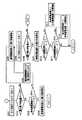
それらプログラムは、図3にフローチャートで概念的に表されている基本制御プログラムを含んでいる。以下、この基本制御プログラムを図3を参照しつつ説明する。
【0057】
この基本制御プログラムがコンピュータ136によって実行されると、まず、ステップS1(以下、単に「S1」で表す。他のステップについても同じとする)において、目標パラメータがコンピュータ136に入力される。具体的には、例えば、住宅12の使用者の意思に基づき、室内の目標温度、目標湿度、実温度の目標温度への目標到達時間、換気時間等が目標パラメータとして入力される。
【0058】
次に、S2において、必要な環境情報がセンサ50および/または通信装置54を用いて取得される。具体的には、例えば、住宅12の内気温、外気温、内湿度、外湿度、天気(日照量との関係)、予想天気、風力等が環境情報として取得される。それら環境情報は、上述の目標パラメータを実現するために各電気機器20に供給することが適当な電気エネルギーを演算する際に、外乱として考慮することが制御精度向上のために望ましい。
【0059】
続いて、S3において、各電気機器20にとっての目標エネルギーを住宅12内のすべての電気機器20について合計したものが住宅12にとっての必要エネルギーとして演算される。各電気機器20にとっての目標エネルギーは、上述の目標パラメータと環境情報とに基づいて演算することが可能である。
【0060】
すなわち、本実施形態においては、各電気機器20の制御に必要な目標値が、エネルギー(仕事量)を複数の電気機器20間において互いに共通する単位として採用した上で演算されるようになっているのである。
【0061】
このS3においては、同じ目標パラメータを実現するために電気機器20の組合せが複数存在する場合には、それら複数の組合せのうち、それを採用した場合に演算されるべき必要エネルギーがそれら複数の組合せのうち最小となるものが選択され、その選択された組合せについて必要エネルギーが演算される。したがって、この演算によれば、同じ目標パラメータを実現するために一斉に駆動される電気機器20の種類すなわち駆動モードが、消費エネルギー節減との関係において最適化されることとなる。
【0062】
その後、S4において、各電気機器20につき、上述の目標パラメータを実現するために各瞬間ごとに各電気機器20に供給すべき電力(または電圧もしくは電流)を演算するために、各パラメータの実際値が目標値すなわち目標パラメータに到達する時間の目標値、すなわち、目標到達時間が演算される。
【0063】
続いて、S5において、発電所80、自然エネルギー発電装置82、自宅蓄電装置30および車両発電・蓄電装置84(以下、それぞれの装置を単に「各発電・蓄電装置」という)との間において通信が行われることにより、後述のエネルギー供給モードを決定するために必要な情報が取得される。各発電・蓄電装置から取得される情報としては、例えば、後述の、各発電・蓄電装置の最大電力供給量、各発電・蓄電装置の実発電量・実蓄電量、各発電・蓄電装置の状態が正常であるか否か等がある。各発電・蓄電装置の実蓄電量には、例えば、自宅蓄電装置30のバッテリ60の充電状態量SOC、車両蓄電装置89のバッテリ88の充電状態量SOC等が含まれる。
【0064】
その後、S6において、上記エネルギー供給モードが決定される。このエネルギー供給モードは、複数の発電・蓄電装置のうち住宅12に電力を供給するために選択すべきものを特定するモードであり、このエネルギー供給モードが決定されれば、少なくとも1つの発電・蓄電装置から住宅12へのエネルギーの供給ルートが特定されることになる。
【0065】
このS6の処理の詳細がエネルギー供給モード決定ルーチンとして図4ないし図6にフローチャートで概念的に表されている。
【0066】
概略的に説明すれば、このエネルギー決定ルーチンにおいては、4つの発電・蓄電装置のうち住宅12にエネルギーを供給することが最適であるものが少なくとも1つ選択されるとともに、その選択された発電・蓄電装置につき、目標送電量、目標発電量および目標蓄電量が演算される。それら発電・蓄電装置についての選択は、本実施形態においては、例えば、使用量の割に安価である種類のエネルギーを利用する発電・蓄電装置を優先的に選択する指針に従って実行されるようになっている。
【0067】
ここに、目標送電量は、各発電・蓄電装置から住宅12に出力すべき電力の目標値を意味し、また、目標発電量は、複数の発電・蓄電装置のうち発電能力を有するものが発電すべき電力の目標値を意味し、また、目標蓄電量は、複数の発電・蓄電装置のうち蓄電能力を有するものが蓄電すべき電力の目標値を意味する。
【0068】
例えば、発電能力を有する発電・蓄電装置が住宅12に電力を目標送電量で実際に供給すれば、それを補充するために同じ発電・蓄電装置が電力をその目標送電量と同じ量で発電することが必要である。したがって、発電能力を有する発電・蓄電装置においては、目標発電量が目標送電量と一致するように演算される可能性がある。
【0069】
同様にして、蓄電能力を有する発電・蓄電装置が住宅12に電力を目標送電量で実際に供給すれば、それを補充するために同じ発電・蓄電装置が電力をその目標送電量と同じ量で蓄電することが必要である。したがって、蓄電能力を有する発電・蓄電装置においては、目標蓄電量が目標送電量と一致するように演算される可能性がある。
【0070】
このS6の実行により、選択された各発電・蓄電装置の目標送電量、目標発電量および目標蓄電量が演算されたならば、続いて、S7において、その選択された各発電・蓄電装置との間において情報通信が行われ、それら演算された目標送電量、目標発電量および目標蓄電量と一致するように、各発電・蓄電装置において実際に処理される目標送電量、目標発電量および目標蓄電量が設定される。この設定に従い、各発電・蓄電装置が作動し、必要エネルギーが住宅12に供給されることとなる。
【0071】
すなわち、本実施形態においては、演算された目標送電量、目標発電量および目標蓄電量と一致するように、各発電・蓄電装置において実際に処理される目標送電量、目標発電量および目標蓄電量を設定するためにエネルギー管理装置10から各発電・蓄電装置に送信される信号が前記(2)項における「要求信号」の一例なのである。
【0072】
その後、S8において、必要な電気機器20の運転がスタートされる。続いて、S9において、各電気機器20におけるECU70と必要な通信が行われる。その後、S10において、電力計74による測定結果を参照することにより、電気機器20によって実際に消費されたエネルギーが演算される。
【0073】
続いて、S11において、その演算された消費エネルギーと、S3において事前に演算された必要エネルギー(消費エネルギーの推定値)との間に設定値以上に大きな差があるという第1の条件が成立したか否かが判定される。さらに、住宅12への供給可能なエネルギーが不足するというような緊急時であるという第2の条件が成立したか否かが判定される。そのような緊急時として、例えば、各発電・蓄電装置の状態が異常である時があり、具体的には、各発電・蓄電装置の最大電力供給量が低下した時、住宅12への主要な電力供給源(例えば、発電所80)からの電力が完全に停止した時がある。
【0074】
このS11においては、それら2つの条件の少なくとも一方でも成立した場合には、各発電・蓄電装置との間において情報通信が行われ、成立した条件の内容に応じた情報が各発電・蓄電装置に送信される。
【0075】
その後、S12において、各発電・蓄電装置の送電量、発電量および蓄電量の各実際値が真の目標値と一致することになるように、各発電・蓄電装置の送電量、発電量および蓄電量の見かけの目標値(各発電・蓄電装置への指令値)が補正される。この補正は、いわゆるフィードバック補正に該当すると考えることが可能である。この補正は、例えば、緊急時である場合に、本来のエネルギーを代替するエネルギーが選択されて住宅12に供給されることとなるように、選択される発電・蓄電装置の種類を変更する処理を含んでいる。
【0076】
続いて、S13において、各発電・蓄電装置との間において情報通信が行われれ、それにより、上記補正が反映されるように各発電・蓄電装置の目標送電量、目標発電量および目標蓄電量の設定が補正される。この補正により、結局、住宅12において各電気機器20を運転するために消費されるエネルギーの量および/または種類すなわち運転モードが変更されることとなる。
【0077】
以上で、この基本制御プログラムの一回の実行が終了し、必要に応じ、次回の実行が再開される。
【0078】
以上の説明から明らかなように、本実施形態においては、エネルギー管理装置10のコンピュータ136のうち、図3のS1を実行する部分が図1における目標設定手段40を構成し、S2を実行する部分が環境情報取得手段42を構成し、S3およびS4を実行する部分が最適駆動モード決定手段44を構成し、S5ないしS10を実行する部分がエネルギー供給モード決定手段46を構成し、S11ないしS13を実行する部分が運転モード変更手段48を構成しているのである。
【0079】
ここで、前記エネルギー供給モード決定ルーチンを図4ないし図6を参照しつつ詳細に説明する。
【0080】
このエネルギー供給モード決定ルーチンにおいては、まず、S101において、自然エネルギーが優先的に住宅12において利用されるようにするため、住宅12に電気エネルギーを供給するために利用すべき発電・蓄電装置の最初の候補として自然エネルギー発電装置82が選択される。
【0081】
本実施形態においては、住宅12に電気エネルギーを供給するために利用可能な発電・蓄電装置として、図1に示すように、発電所80と、自然エネルギー発電装置82と、自宅蓄電装置30と、車両発電装置86と、車両蓄電装置89とがあるが、それら発電・蓄電装置には、各発電・蓄電装置が同じ量のエネルギーを生成するために必要な費用に関して所定の順序が割り当てられる。この順序は、例えば、自然エネルギー発電装置82、自宅蓄電装置30、車両蓄電装置89、車両発電装置86および発電所80の順に費用が増加するというものである。
【0082】
そこで、本実施形態においては、それら複数種類のエネルギーのうち最も安価な自然エネルギーを利用して住宅12の電力料金を極力低く抑えるべく、S101において、住宅12が利用すべき発電・蓄電装置として自然エネルギー発電装置82が優先的に選択される。
【0083】
次に、S102において、その選択された自然エネルギー発電装置82の最大電力供給量が十分であるか否かが判定される。具体的には、自然エネルギー発電装置82の最大電力供給量が、前記演算された必要エネルギーより大きいか否かが判定されるのである。
【0084】
今回は、自然エネルギー発電装置82の最大電力供給量が十分であると仮定すれば、S102の判定がYESとなり、S103において、自然エネルギー発電装置82が住宅12に出力すべき電力の目標値(前記目標送電量)が、前記必要エネルギーと等しくなるように設定される。さらに、自然エネルギー発電装置82と住宅12とが電気的に接続され(リレー92がONされ)、それにより、自然エネルギー発電装置82から住宅12への電力供給が開始される。
【0085】
なお付言すれば、このS103の実行後直ちに、自然エネルギー発電装置82から住宅12への電力供給が開始されるわけではない。このS103の実行後に図3のS7において各発電・蓄電装置との通信が行われた後にはじめて、自然エネルギー発電装置82から住宅12への電力供給が開始される。すなわち、このS103においては、厳密には、自然エネルギー発電装置82から住宅12への電力供給が開始されることを許可する指令が出されるのみで、その指令の実行までは行われないのである。
【0086】
このことは、他の同様なステップについても同じであるが、説明を簡単にするために、以下、各ステップに該当する指令について直接言及することなく、その指令が直ちに実行されたと仮定して各ステップの内容を説明することとする。
【0087】
続いて、S104において、自宅蓄電装置30のバッテリ60の充電状態量SOC(state of charge)、すなわち、バッテリ60の残存容量が設定値α1より小さいか否かが判定される。この判定は、自宅蓄電装置30のバッテリ60の充電の要否を判定するために行われる。ここに、充電状態量SOCは、各瞬間においてバッテリ60に残存する電力量を、満充電状態を基準にし、パーセントを単位として表現する物理量である。また、設定値α1の一例は、80パーセントである。
【0088】
今回は、自宅蓄電装置30の充電状態量SOCが設定値α1より小さくはない、すなわち、自宅蓄電装置30の充電が必要ではないと仮定すれば、S104の判定がNOとなり、S105において、車両蓄電装置89のバッテリ88の充電状態量SOCが設定値α1より小さいか否かが判定される。この判定は、車両蓄電装置89のバッテリ88の充電の要否を判定するために行われる。
【0089】
今回は、車両蓄電装置89の充電状態量SOCが設定値α1より小さくはない、すなわち、車両蓄電装置89の充電が必要ではないと仮定すれば、S105の判定がNOとなり、S106において、自然エネルギー発電装置82による発電量の目標値(前記目標発電量)が前記必要エネルギーと等しくなるように設定される。これにより、自然エネルギー発電装置82が、住宅12との関係において必要以上となる電気エネルギーを発電しないように制限される。
【0090】
以上で、このエネルギー供給モード決定ルーチンの一回の実行が終了する。
【0091】
これに対し、今回は、自宅蓄電装置30の充電状態量SOCが設定値α1より小さい、すなわち、自宅蓄電装置30の充電が必要であると仮定すれば、S104の判定がYESとなり、S107において、自然エネルギー発電装置82の余剰エネルギーが自宅蓄電装置30に供給される。
【0092】
具体的には、自然エネルギー発電装置82が自宅蓄電装置30に出力すべき電力の目標値が、自然エネルギー発電装置82の最大電力供給量から前記必要エネルギーを控除した値と等しくなるように設定される。さらに、自然エネルギー発電装置82と自宅蓄電装置30とが電気的に接続され(リレー102とリレー62とがONされ)、それにより、自然エネルギー発電装置82によって自宅蓄電装置30の充電が開始される。
【0093】
以上で、このエネルギー供給モード決定ルーチンの一回の実行が終了する。
【0094】
これに対し、今回は、自宅蓄電装置30の充電状態量SOCは設定値α1より小さくはないが、車両蓄電装置89の充電状態量SOCは設定値α1より小さい、すなわち、車両蓄電装置89の充電が必要であると仮定すれば、S104の判定はNO、S105の判定はYESとなり、S108において、自然エネルギー発電装置82の余剰エネルギーが車両蓄電装置89に供給される。
【0095】
具体的には、自然エネルギー発電装置82が車両蓄電装置89に出力すべき電力の目標値が、自然エネルギー発電装置82の最大電力供給量から前記必要エネルギーを控除した値と等しくなるように設定される。さらに、自然エネルギー発電装置82と車両蓄電装置89とが電気的に接続され(リレー102とリレー101とがONされ)、それにより、自然エネルギー発電装置82によって車両蓄電装置89の充電が開始される。
【0096】
以上で、このエネルギー供給モード決定ルーチンの一回の実行が終了する。
【0097】
以上、自然エネルギー発電装置82の最大電力供給量が住宅12との関係において十分である場合を説明したが、十分ではない場合には、S102の判定がNOなり、S109以下のステップに移行する。それらステップにおいては、自然エネルギー発電装置82と他の発電・蓄電装置との組合せによって住宅12への電力供給が行われる。
【0098】
具体的には、S109において、自然エネルギー発電装置82から住宅12に供給すべき電力の目標値が、その自然エネルギー発電装置82の最大電力供給量と等しくなるように設定される。さらに、自然エネルギー発電装置82と住宅12とが電気的に接続され(リレー92がONされ)、それにより、自然エネルギー発電装置82から住宅12への電力供給が開始される。
【0099】
その後、S110において、住宅12において次に安価なエネルギーを利用すべく、自宅蓄電装置30が選択される。この選択の結果、住宅12に必要な電気エネルギーが、自然エネルギー発電装置82と自宅蓄電装置30との双方を利用して提供されることとなる。
【0100】
続いて、S111において、自宅蓄電装置30の最大電力供給量が十分であるか否かが判定される。具体的には、自宅蓄電装置30の最大電力供給量が、自然エネルギー発電装置82のみを利用する場合の不足エネルギー量、すなわち、前記必要エネルギーから自然エネルギー発電装置82の実電力供給量(電力計112による測定値)を控除した値より大きいか否かが判定される。
【0101】
今回は、自宅蓄電装置30の最大電力供給量が十分であると仮定すれば、S111の判定がYESとなり、S112において、自宅蓄電装置30のバッテリ60の充電状態量SOCが設定値α2より大きいか否か、すなわち、そのバッテリ60からの放電が適当であるか否かが判定される。設定値α2の一例は、60パーセントである。
【0102】
今回は、自宅蓄電装置30の充電状態量SOCが設定値α2より大きいと仮定すれば、S112の判定がYESとなり、S113において、自宅蓄電装置30が住宅12に出力すべき電力の目標値が、自然エネルギー発電装置82のみを利用する場合の不足エネルギー量、すなわち、前記必要エネルギーから自然エネルギー発電装置82の実電力供給量(電力計112による測定値)を控除した値と等しくなるように設定される。さらに、自宅蓄電装置30と住宅12とが電気的に接続され(リレー64がONされ)、それにより、自宅蓄電装置30から住宅12への電力供給が開始される。
【0103】
これに対し、今回は、自宅蓄電装置30の充電状態量SOCが設定値α2より大きくはない、すなわち、自宅蓄電装置30の放電が適当ではないと仮定すれば、S112の判定がNOとなり、S114において、自宅蓄電装置30と住宅12とが電気的に切断され(リレー64がOFFされ)、それにより、自宅蓄電装置30から住宅12への電力供給が阻止される。その後、図5のS201に移行する。
【0104】
これに対し、今回は、自宅蓄電装置30の最大電力供給量が十分ではないと仮定すれば、S111の判定がNOとなり、S115において、自宅蓄電装置30から住宅12に供給すべき電力の目標値が、その自宅蓄電装置30の最大電力供給量と等しくなるように設定される。さらに、自宅蓄電装置30と住宅12とが電気的に接続され(リレー64がONされ)、それにより、自宅蓄電装置30から住宅12への電力供給が開始される。その後、図5のS201に移行する。
【0105】
図5のS201においては、住宅12において次に安価なエネルギーを利用すべく、車両蓄電装置89が選択される。
【0106】
続いて、S202において、車両蓄電装置89の最大電力供給量が十分であるか否かが判定される。具体的には、車両蓄電装置89の最大電力供給量が、自然エネルギー発電装置82および自宅蓄電装置30のみを利用する場合の不足エネルギー量、すなわち、前記必要エネルギーから自然エネルギー発電装置82の実電力供給量(電力計112による測定値)と自宅蓄電装置30の実電力供給量(電力計115による測定値)との和を控除した値より大きいか否かが判定される。
【0107】
今回は、車両蓄電装置89の最大電力供給量が十分であると仮定すれば、S202の判定がYESとなり、S203において、車両蓄電装置89のバッテリ88の充電状態量SOCが設定値α2より大きいか否か、すなわち、そのバッテリ88からの放電が適当であるか否かが判定される。
【0108】
今回は、車両蓄電装置89の充電状態量SOCが設定値α2より大きいと仮定すれば、S203の判定がYESとなり、S204において、車両蓄電装置89が住宅12に出力すべき電力の目標値が、自然エネルギー発電装置82および自宅蓄電装置30のみを利用する場合の不足エネルギー量、すなわち、前記必要エネルギーから自然エネルギー発電装置82の実電力供給量(電力計112による測定値)と自宅蓄電装置30の実電力供給量(電力計115による測定値)との和を控除した値と等しくなるように設定される。さらに、車両蓄電装置89と住宅12とが電気的に接続され(リレー94がONされ)、それにより、車両蓄電装置89から住宅12への電力供給が開始される。
【0109】
これに対し、今回は、車両蓄電装置89の充電状態量SOCが設定値α2より大きくはない、すなわち、車両蓄電装置89の放電が適当ではないと仮定すれば、S203の判定がNOとなり、S205において、車両蓄電装置89と住宅12とが電気的に切断され(リレー94がOFFされ)、それにより、車両蓄電装置89から住宅12への電力供給が阻止される。その後、S206に移行する。
【0110】
これに対し、今回は、車両蓄電装置89の最大電力供給量が十分ではないと仮定すれば、S202の判定がNOとなり、S207において、車両蓄電装置89から住宅12に供給すべき電力の目標値が、その車両蓄電装置89の最大電力供給量と等しくなるように設定される。さらに、車両蓄電装置89と住宅12とが電気的に接続され(リレー94がONされ)、それにより、車両蓄電装置89から住宅12への電力供給が開始される。その後、S206に移行する。
【0111】
このS206においては、住宅12において次に安価なエネルギーを利用すべく、車両蓄電装置89が選択される。
【0112】
続いて、S208において、車両発電装置86の最大電力供給量が十分であるか否かが判定される。具体的には、車両発電装置86の最大電力供給量が、自然エネルギー発電装置82、自宅蓄電装置30および車両蓄電装置89のみを利用する場合の不足エネルギー量、すなわち、前記必要エネルギーから自然エネルギー発電装置82の実電力供給量(電力計112による測定値)と自宅蓄電装置30の実電力供給量(電力計115による測定値)と車両蓄電装置89の実電力供給量(電力計117による測定値)との和を控除した値より大きいか否かが判定される。
【0113】
今回は、車両発電装置86の最大電力供給量が十分であると仮定すれば、S208の判定がYESとなり、S209において、車両発電装置86が住宅12に出力すべき電力の目標値が、前記必要エネルギーから、自然エネルギー発電装置82の実電力供給量(電力計112による測定値)と、自宅蓄電装置30の実電力供給量(電力計115による測定値)と、車両蓄電装置89の実電力供給量(電力計117による測定値)とを控除した値と等しくなるように設定される。さらに、車両発電装置86と住宅12とが電気的に接続され(リレー96がONされ)、それにより、車両発電装置86から住宅12への電力供給が開始される。
【0114】
続いて、S210において、自宅蓄電装置30のバッテリ60の充電状態量SOCが設定値α1より小さいか否か、すなわち、自宅蓄電装置30のバッテリ60の充電が必要であるか否かが判定される。今回は、自宅蓄電装置30の充電状態量SOCが設定値α1より小さくはない、すなわち、自宅蓄電装置30の充電が必要ではないと仮定すれば、S210の判定がNOとなり、S211に移行する。
【0115】
このS211においては、車両蓄電装置89のバッテリ88の充電状態量SOCが設定値α1より小さいか否か、すなわち、車両蓄電装置89のバッテリ88の充電が必要であるか否かが判定される。今回は、車両蓄電装置89の充電状態量SOCが設定値α1より小さくはない、すなわち、車両蓄電装置89の充電が必要ではないと仮定すれば、S211の判定がNOとなり、以上で、このエネルギー供給モード決定ルーチンの一回の実行が終了する。
【0116】
これに対し、今回は、自宅蓄電装置30の充電状態量SOCが設定値α1より小さい、すなわち、自宅蓄電装置30の充電が必要であると仮定すれば、S210の判定がYESとなり、S212において、車両発電装置86の余剰エネルギーが自宅蓄電装置30に供給される。
【0117】
具体的には、このS212においては、車両発電装置86が自宅蓄電装置30に出力すべき電力の目標値が、車両発電装置86の最大電力供給量からそれの実電力供給量(電力計112による測定値)を控除した値と等しくなるように設定される。さらに、車両発電装置86と自宅蓄電装置30とが電気的に接続され(リレー103とリレー62とがONされ)、それにより、車両発電装置86によって自宅蓄電装置30の充電が開始される。
【0118】
以上で、このエネルギー供給モード決定ルーチンの一回の実行が終了する。
【0119】
これに対し、今回は、自宅蓄電装置30の充電は不要であるが、車両蓄電装置89の充電は必要であると仮定すれば、S210の判定はNO、S211の判定はYESとなり、S213において、車両発電装置86の余剰エネルギーが車両蓄電装置89に供給される。
【0120】
具体的には、このS213においては、車両発電装置86が車両蓄電装置89に出力すべき電力の目標値が、車両発電装置86の最大電力供給量からそれの実電力供給量(電力計119による測定値)を控除した値と等しくなるように設定される。さらに、車両発電装置86と車両蓄電装置89とが電気的に接続され(リレー103とリレー104とがONされ)、それにより、車両発電装置86によって車両蓄電装置89の充電が開始される。
【0121】
以上で、このエネルギー供給モード決定ルーチンの一回の実行が終了する。
【0122】
以上、車両発電装置86の最大電力供給量が住宅12との関係において十分である場合を説明したが、十分ではない場合には、S208の判定がNOとなり、図6のS301に移行する。
【0123】
このS301においては、車両発電装置86と住宅12とが電気的に接続され(リレー96がONされ)、それにより、車両発電装置86から住宅12への電力供給が開始される。続いて、S302において、住宅12において次に安価なエネルギーを利用すべく、発電所80が選択される。
【0124】
その後、S303において、車両発電装置86が住宅12に出力すべき電力の目標値が、前記必要エネルギーから、自然エネルギー発電装置82の実電力供給量(電力計112による測定値)と、自宅蓄電装置30の実電力供給量(電力計115による測定値)と、車両蓄電装置89の実電力供給量(電力計117による測定値)と、車両発電装置86の実電力供給量(電力計119による測定値)とを控除した値と等しくなるように設定される。さらに、発電所80と住宅12とが電気的に接続され(リレー90がONされ)、それにより、発電所80から住宅12への電力供給が開始される。
【0125】
続いて、S304において、自宅蓄電装置30のバッテリ60の充電状態量SOCが設定値α1より小さいか否か、すなわち、自宅蓄電装置30のバッテリ60の充電が必要であるか否かが判定される。今回は、自宅蓄電装置30の充電状態量SOCが設定値α1より小さくはないと仮定すれば、S304の判定がNOとなり、S305に移行する。
【0126】
このS305においては、車両蓄電装置89のバッテリ88の充電状態量SOCが設定値α1より小さいか否か、すなわち、車両蓄電装置89のバッテリ88の充電が必要であるか否かが判定される。今回は、車両蓄電装置89の充電状態量SOCが設定値α1より小さくはないと仮定すれば、S305の判定がNOとなり、S306に移行する。
【0127】
このS306においては、発電所80の目標発電量が、前記必要エネルギーから、自然エネルギー発電装置82の実電力供給量(電力計112による測定値)と、自宅蓄電装置30の実電力供給量(電力計115による測定値)と、車両蓄電装置89の実電力供給量(電力計117による測定値)と、車両発電装置86の実電力供給量(電力計119による測定値)とを控除した値と等しくなるように設定される。
【0128】
以上で、このエネルギー供給モード決定ルーチンの一回の実行が終了する。
【0129】
これに対し、今回は、自宅蓄電装置30の充電状態量SOCが設定値α1より小さい、すなわち、自宅蓄電装置30の充電が必要であると仮定すれば、S304の判定がYESとなり、S307において、発電所80の余剰エネルギーが自宅蓄電装置30に供給される。
【0130】
具体的には、このS307においては、発電所80が自宅蓄電装置30に出力すべき電力の目標値が、発電所80の最大電力供給量からそれの実電力供給量(電力計110による測定値)を控除した値と等しくなるように設定される。さらに、発電所80と自宅蓄電装置30とが電気的に接続され(リレー100とリレー62とがONされ)、それにより、発電所80によって自宅蓄電装置30の充電が開始される。
【0131】
以上で、このエネルギー供給モード決定ルーチンの一回の実行が終了する。
【0132】
これに対し、今回は、自宅蓄電装置30の充電は不要であるが、車両蓄電装置89の充電は必要であると仮定すれば、S304の判定はNO、S305の判定はYESとなり、S308において、発電所80の余剰エネルギーが車両蓄電装置89に供給される。
【0133】
具体的には、このS308においては、発電所80が車両蓄電装置89に出力すべき電力の目標値が、発電所80の最大電力供給量からそれの実電力供給量(電力計110による測定値)を控除した値と等しくなるように設定される。さらに、発電所80と車両蓄電装置89とが電気的に接続され(リレー100とリレー101とがONされ)、それにより、発電所80によって車両蓄電装置89の充電が開始される。
【0134】
以上で、このエネルギー供給モード決定ルーチンの一回の実行が終了する。
【0135】
以上の説明から明らかなように、本実施形態においては、通信装置54と、コンピュータ136のうち、図3におけるS5を実行する部分とが互いに共同して前記(1)項における「情報交換部」の一例を構成し、コンピュータ136のうち、図3におけるS6、S7、S11、S12およびS13を実行する部分が同項における「供給制御部」の一例を構成しているのである。
【0136】
さらに、本実施形態においては、コンピュータ136のうち、図3におけるS7を実行する部分が前記(2)項における「送信手段」の一例を構成しているのである。
【0137】
さらに、本実施形態においては、コンピュータ136のうち、図3におけるS5を実行する部分が前記(4)項における「交換手段」の一例を構成しているのである。
【0138】
さらに、本実施形態においては、コンピュータ136のうち、図3におけるS3を実行する部分が前記(8)項における「制御手段」の一例を構成しているのである。
【0139】
以上、本発明の一実施形態を図面に基づいて詳細に説明したが、これは例示であり、前記[課題を解決するための手段および発明の効果]の欄に記載の態様を始めとして、当業者の知識に基づいて種々の変形、改良を施した他の形態で本発明を実施することが可能である。
【図面の簡単な説明】
【図1】本発明の一実施形態に従うエネルギー管理装置を備えた自エネルギ関連システムと他エネルギー関連システムとをそれぞれ概念的に表すとともに、それら両システム間の接続関係を概念的に表す示すブロック図である。
【図2】図1におけるエネルギー管理装置10のハードウエア構成を系統的に表すブロック図である。
【図3】図2におけるメモリ132に記憶されている基本制御プログラムの内容を概念的に表すフローチャートである。
【図4】図3におけるS6の詳細であるエネルギー供給モード決定ルーチンの一部を概念的に表すフローチャートである。
【図5】上記エネルギー供給モード決定ルーチンの別の一部を概念的に表すフローチャートである。
【図6】上記エネルギー供給モード決定ルーチンのさらに別の一部を概念的に表すフローチャートである。
【符号の説明】
10 エネルギー管理装置
12 住宅
20 電気機器
30 自宅蓄電装置
46 エネルギー供給モード決定手段
54 通信装置
80 発電所
82 自然エネルギー発電装置
84 車両発電・蓄電装置
86 車両発電装置
89 車両蓄電装置
136 コンピュータ[0001]
BACKGROUND OF THE INVENTION
The present invention relates to a technique for managing the exchange of energy between a plurality of energy-related systems.
[0002]
[Prior art]
A technique for managing the exchange of energy between a plurality of energy-related systems is already known (for example, see Patent Document 1).
[0003]
[Patent Document 1]
JP 2001-8380 A
This patent document 1 describes a system that can transmit electric power between an electric vehicle and a house. Specifically, in this system, charging of an electric vehicle battery is performed by a household power source in a house, and electric power is supplied from the battery of the electric vehicle to the household power source.
[0004]
[Problems to be solved by the invention]
According to this conventional system, power supply from the electric vehicle to the house is ensured so that the battery of the electric vehicle secures the amount of power required for normal use of the electric vehicle, that is, the round trip of the user's daily life. Done. Therefore, even when the electric vehicle is unexpectedly used, the use thereof is not hindered.
[0005]
However, in this conventional system, the electric vehicle unilaterally supplies power to the house regardless of whether or not the house requires external power supply. In other words, even if the house does not really need external power, it is inevitable that power is supplied from the electric vehicle to the house. For this reason, in this conventional system, the possibility that the power supply from the electric vehicle to the house is wasted cannot be completely excluded.
[0006]
Against the background described above, the present invention is a technique for managing the transfer of energy between a plurality of energy-related systems, and to accurately supply energy from one energy-related system to another energy-related system. It was made as.
[0007]
[Means for Solving the Problems and Effects of the Invention]
The following aspects are obtained by the present invention. Each mode is divided into sections, each section is numbered, and is described in a form that cites other section numbers as necessary. This is to facilitate understanding of some of the technical features described herein and some of the combinations thereof. The technical features and combinations of the technical features described herein are It should not be construed as limited.
(1)A self-energy-related system that is physically independentA consumption department that consumes energy;ElectricalAn accumulator that accumulates energy;ElectricalGenerator that generates energyAndIncluded as energy-related elementsSeeConsumption unit, storage unit and generation unitAndInclude as energy-related elementsIt is a physically independent moving bodyEnergy can be exchanged with other energy-related systemsSelf-energy related systemInElectricalManage energyIncluded in self-energy related systemsAn energy management device,
Between the self energy related system and the other energy related systemThe other energy related through communicationIn the systemElectricalEnergy consumption, storage and productionOurat leastAccumulationInformation aboutGetInformationGetAnd
ThatGetThe self-energy related system based on the informationFromOther energy related systemsToofElectricalA supply control unit that controls the supply of energy;
IncludingIn addition, the information acquisition unit is configured to communicate information between the own energy related system and the other energy related system before the own energy related system and the other energy related system are physically connected. The supply control unit obtains the self energy related system and the other energy related system based on the content of information acquired before the self energy related system and the other energy related system are physically connected. The electrical energy supplied from the self-energy related system to the other energy-related system after the system is physically connected before the self-energy related system and the other energy-related system are physically connected. Generated and accumulated in the self-energy related system,Energy management device.
(2) a self-energy-related system that is physically independent, and at least a consumption unit of a consumption unit that consumes electrical energy, a storage unit that accumulates electrical energy, and a generation unit that generates electrical energy; A physically independent mobile body that includes, as energy-related elements, a storage section that stores electrical energy generated by a generation section outside the self-energy-related system, and includes a consumption section, a storage section, and a generation section as energy-related elements An energy management device included in the self-energy-related system that manages electrical energy in the self-energy-related system that can exchange energy with other energy-related systems.
An information acquisition unit that acquires information on at least accumulation of consumption, accumulation, and generation of electrical energy in the other energy related system via communication between the self energy related system and the other energy related system;
Based on the content of the acquired information, a supply control unit that controls the supply of electrical energy from the own energy related system to the other energy related system;
The information acquisition unit includes a communication between the self energy related system and the other energy related system before the self energy related system and the other energy related system are physically connected. The information is acquired, and the supply control unit is configured to determine whether the own energy-related system and the other energy are based on the content of the information acquired before the own energy-related system and the other energy-related system are physically connected. The electrical energy supplied from the self-energy related system to the other energy-related system after the related system is physically connected before the self-energy related system and the other energy-related system are physically connected. In addition, it accumulates from the external generation unit in the self-energy related system. To, energy management device.
[0008]
According to this device, between energy related systemsElectricalPrior to giving and receiving energyOther energy relatedIn the systemElectricalEnergy consumption, storage and productionOurat leastAccumulationInformation aboutGetIt becomes possible to do.
[0009]
Therefore, according to this device, for example,otherEnergy related systemsElectricalEnergySelfWhen it is necessary to take in energy-related systemsSelfEnergy related systemsotherIt is possible to determine in advance whether or not it is appropriate to be an energy supply source for an energy-related system. Thus, it becomes possible to select an energy supply source in consideration of the circumstances of the partner's energy-related system, and as a result, it becomes easy to select an energy supply source accurately.
[0010]
Further, according to this device, for example, when the self-energy related system intends to supply energy to another energy-related system, whether or not the other energy-related system needs to supply energy from the self-energy related system. Can be determined in advance. In this way, it is possible to select an energy supply destination in consideration of the circumstances of the partner's energy-related system. As a result, it is possible to accurately determine whether energy supply is necessary and to select an energy supply destination. It becomes easy to do accurately.
[0012]
In addition, the “energy-related system” in this section may be configured to have, for example, a property of fixing to land (real estate property), or to have mobility or portability (movable property). Is possible.
[0013]
Examples of energy-related systems having real estate properties include: (a) a house (including personal residences and collective residences) that usually has at least a consumption unit, and in some cases has a generation unit and / or storage unit (b) There are power plants that exclusively generate power, (c) solar power, wind power, etc., and natural energy power generators that generate power using free natural energy.
[0014]
On the other hand, examples of energy-related systems having movable properties include vehicles (including automobiles and motorcycles) as moving bodies having a consumption unit, an accumulation unit, and a generation unit.
[0015]
Therefore, as a relationship between “own energy related system” and “other energy related system”, for example,Houses and vehiclesThere is.
[0016]
In addition, the “energy-related system” in this section is a system that has physical independence from other energy-related systems, for example, but has dependency on other energy-related systems from the viewpoint of energy. Can be defined as
[0022]
According to this device, it is different from the case where information cannot be exchanged after shifting from a state in which energy cannot be exchanged electrically to a state in which energy can be exchanged between the own energy-related system and another energy-related system. From the beginning of the transition to a state in which such energy can be exchanged electrically, it is easy to accurately exchange the energy in consideration of the state and demand of both systems.
[0023]
For example, if the device according to this section is applied to an environment in which one of the two systems is a battery of an electric vehicle and the other is a power generation / storage device, for example, it becomes necessary to charge the battery of the electric vehicle. In this case, prior to the electric vehicle arriving at the power generation / storage device, the power generation / storage device can be operated according to the power demand of the electric vehicle. For example, prior to the arrival of an electric vehicle, the power generation unit of the power generation / storage device performs power generation, and the generated electric power is stored in the storage unit of the power generation / storage device so that the electric vehicle arrives. Then, the electric power stored in the power storage unit can be supplied to the electric vehicle.
[0027]
DETAILED DESCRIPTION OF THE INVENTION
Hereinafter, one of more specific embodiments of the present invention will be described in detail with reference to the drawings.
[0028]
FIG. 1 conceptually shows a hardware configuration of a
[0029]
In the present embodiment, the
[0030]
As shown in the functional block diagram of FIG. 1, the
[0031]
Although details of these means will be described later, the
[0032]
As shown in FIG. 1, the home power storage device 30 is configured to include a
[0033]
In any case, the home power storage device 30 can perform wired or wireless communication with the
[0034]
Furthermore, as shown by a solid line in FIG. 1, the home power storage device 30 is configured to selectively store electric energy supplied from the outside via the relay 62 in the
[0035]
The home power storage device 30 performs the above communication and controls the ON / OFF of the
[0036]
As shown in FIG. 1, each electric device 20 in the
[0037]
In addition, in this specification, the term “electric power” may mean electric power (work rate) in a narrow sense and may mean electric energy (work amount) or electric energy that is electric power in a broad sense. , It is interpreted elastically depending on the context in which the term is used.
[0038]
As shown in FIG. 1, the
[0039]
The power plant 80 is a facility that generates electrical energy using energy that has been widely used in the past, such as thermal energy, nuclear energy, and hydraulic energy. The natural energy power generation apparatus 82 is an apparatus that generates electric energy using inexpensive energy that does not require a large-scale facility such as wind energy and solar energy.
[0040]
The vehicle is configured to include a
[0041]
As shown by a broken line in FIG. 1, the
[0042]
Furthermore, as shown by a thin solid line in FIG. 1, electrical energy can be supplied to the
[0043]
Specifically, the generated power at the power plant 80 can be supplied to the plurality of electrical devices 20 in the
[0044]
In addition, the home power storage device 30 can be physically associated with the
[0045]
Therefore, if the home power storage device 30 is physically classified, it can be considered that the home power storage device 30 constitutes a part of the self-energy related system, but at the present time, it is not so popular to install the power storage device in the
[0046]
Electric energy is accumulated from the generation site between the power plant 80, the natural energy power generation device 82 and the vehicle
[0047]
Specifically, the generated power at the power plant 80 is stored in the home power storage device 30 via the relay 100 and in the
[0048]
Further, the power generated by the vehicle
[0049]
Furthermore, in the present embodiment, the generated power at the power plant 80 and the generated power at the natural energy power generation device 82 can be taken into the vehicle
[0050]
As is clear from the above description, in this embodiment, both information exchange and electric energy transfer are possible between a plurality of energy-related systems.
[0051]
As shown in FIG. 1, each relay flowed through a power plant 80, a natural energy power generation device 82, a home power storage device 30, and a vehicle power generation / power storage device 84 (hereinafter also referred to as “a plurality of power generation / power storage devices”). A wattmeter is provided to measure the power.
[0052]
Specifically, in the power plant 80, the electric power flowing through the
[0053]
Each power generation / storage device is also provided with a
[0054]
Further, the power plant 80, the natural energy power generation device 82, and the vehicle power generation / storage device 84, like the home storage device 30, have a function of communicating with the
[0055]
FIG. 2 conceptually shows the hardware configuration of the
[0056]
These programs include a basic control program conceptually represented in the flowchart of FIG. The basic control program will be described below with reference to FIG.
[0057]
When this basic control program is executed by the
[0058]
Next, in S <b> 2, necessary environmental information is acquired using the sensor 50 and / or the
[0059]
Subsequently, in S <b> 3, the sum of the target energy for each electrical device 20 for all the electrical devices 20 in the
[0060]
That is, in the present embodiment, the target value necessary for control of each electric device 20 is calculated after adopting energy (work amount) as a unit common to the plurality of electric devices 20. It is.
[0061]
In this S3, when there are a plurality of combinations of the electric devices 20 in order to realize the same target parameter, the required energy to be calculated when the combination is adopted among the combinations is the combination of the plurality of combinations. The smallest one is selected, and the required energy is calculated for the selected combination. Therefore, according to this calculation, the types of the electric devices 20 that are driven all at once to achieve the same target parameter, that is, the driving mode, are optimized in relation to the energy consumption saving.
[0062]
After that, in S4, in order to calculate the electric power (or voltage or current) to be supplied to each electric device 20 at each moment in order to realize the above-described target parameter, the actual value of each parameter is calculated in S4. Is a target value, that is, a target value of a time for reaching the target parameter, that is, a target arrival time.
[0063]
Subsequently, in S5, communication is performed with the power plant 80, the natural energy power generation device 82, the home power storage device 30, and the vehicle power generation / power storage device 84 (hereinafter, each device is simply referred to as “each power generation / power storage device”). As a result, information necessary for determining an energy supply mode to be described later is acquired. Information acquired from each power generation / storage device includes, for example, a maximum power supply amount of each power generation / storage device, an actual power generation amount / actual storage amount of each power generation / storage device, and a state of each power generation / storage device, which will be described later Whether or not is normal. The actual power storage amount of each power generation / storage device includes, for example, the charge state amount SOC of the
[0064]
Thereafter, in S6, the energy supply mode is determined. This energy supply mode is a mode for identifying one of a plurality of power generation / storage devices that should be selected for supplying power to the
[0065]
The details of the process of S6 are conceptually represented by flowcharts in FIGS. 4 to 6 as an energy supply mode determination routine.
[0066]
In brief, in this energy determination routine, at least one of the four power generation / storage devices that is most suitable for supplying energy to the
[0067]
Here, the target power transmission amount means a target value of the power to be output from each power generation / storage device to the
[0068]
For example, if a power generation / storage device having a power generation capability actually supplies power to the
[0069]
Similarly, if a power generation / storage device having a storage capacity actually supplies power to the
[0070]
If the target power transmission amount, the target power generation amount, and the target power storage amount of each selected power generation / storage device are calculated by the execution of S6, subsequently, in S7, the selected power generation / storage device is connected to each selected power generation / storage device. Information communication is performed, and the target power transmission amount, target power generation amount, and target power storage actually processed in each power generation / storage device so as to match the calculated target power transmission amount, target power generation amount, and target power storage amount. The amount is set. In accordance with this setting, each power generation / storage device operates, and necessary energy is supplied to the
[0071]
That is, in the present embodiment, the target power transmission amount, the target power generation amount, and the target power storage amount that are actually processed in each power generation / storage device so as to coincide with the calculated target power transmission amount, target power generation amount, and target power storage amount. The signal transmitted from the
[0072]
Thereafter, in S8, necessary operation of the electric device 20 is started. Subsequently, in S9, necessary communication with the
[0073]
Subsequently, in S11, a first condition is established that there is a greater difference than the set value between the calculated energy consumption and the necessary energy (estimated energy consumption) calculated in advance in S3. It is determined whether or not. Furthermore, it is determined whether or not the second condition that the emergency is such that the energy that can be supplied to the
[0074]
In S11, when at least one of the two conditions is satisfied, information communication is performed with each power generation / storage device, and information according to the content of the satisfied condition is transmitted to each power generation / storage device. Sent.
[0075]
Thereafter, in S12, the power transmission amount, the power generation amount and the power storage amount of each power generation / storage device so that the actual power transmission amount, the power generation amount and the power storage amount of each power generation / power storage device coincide with the true target value. The apparent target value of the quantity (command value to each power generation / storage device) is corrected. This correction can be considered as corresponding to so-called feedback correction. For example, in the case of an emergency, the correction is performed by changing the type of the selected power generation / storage device so that the energy that replaces the original energy is selected and supplied to the
[0076]
Subsequently, in S13, information communication is performed with each power generation / storage device, and thereby the target power transmission amount, target power generation amount, and target power storage amount of each power generation / storage device are reflected so that the correction is reflected. The setting is corrected. As a result of this correction, the amount and / or type of energy consumed for operating each electric device 20 in the
[0077]
Thus, one execution of the basic control program is completed, and the next execution is resumed as necessary.
[0078]
As is clear from the above description, in the present embodiment, in the
[0079]
Here, the energy supply mode determination routine will be described in detail with reference to FIGS.
[0080]
In this energy supply mode determination routine, first, in step S101, in order to preferentially use natural energy in the
[0081]
In the present embodiment, as a power generation / storage device that can be used to supply electrical energy to the
[0082]
Therefore, in the present embodiment, in order to keep the electricity rate of the
[0083]
Next, in S102, it is determined whether or not the maximum power supply amount of the selected natural energy power generation device 82 is sufficient. Specifically, it is determined whether or not the maximum power supply amount of the natural energy power generation device 82 is larger than the calculated required energy.
[0084]
If it is assumed that the maximum power supply amount of the natural energy power generation device 82 is sufficient this time, the determination in S102 is YES, and in S103, the target value of the power that the natural energy power generation device 82 should output to the house 12 (the above-described value). Target transmission amount) is set to be equal to the required energy. Furthermore, the natural energy power generation device 82 and the
[0085]
In addition, immediately after the execution of S103, power supply from the natural energy power generation device 82 to the
[0086]
This is the same for other similar steps, but for the sake of simplicity, in the following, it will be assumed that the command has been executed immediately without referring directly to the command applicable to each step. The contents of the step will be explained.
[0087]
Subsequently, in S104, it is determined whether or not the state of charge (SOC) of the
[0088]
This time, assuming that the state of charge SOC of the home power storage device 30 is not smaller than the set value α1, that is, it is not necessary to charge the home power storage device 30, the determination in S104 is NO, and in S105, the vehicle power storage It is determined whether or not the state of charge SOC of the
[0089]
This time, if it is assumed that the state of charge SOC of the vehicle power storage device 89 is not smaller than the set value α1, that is, it is not necessary to charge the vehicle power storage device 89, the determination in S105 is NO, and in S106, the natural energy The target value of the power generation amount by the power generator 82 (the target power generation amount) is set to be equal to the required energy. Thereby, the natural energy power generation device 82 is restricted so as not to generate electric energy that is more than necessary in the relationship with the
[0090]
This completes one execution of the energy supply mode determination routine.
[0091]
On the other hand, this time, if it is assumed that the state of charge SOC of home power storage device 30 is smaller than set value α1, that is, it is necessary to charge home power storage device 30, the determination in S104 is YES, and in S107, Surplus energy of the natural energy power generation device 82 is supplied to the home power storage device 30.
[0092]
Specifically, the target value of the power that the natural energy power generation device 82 should output to the home power storage device 30 is set to be equal to the value obtained by subtracting the necessary energy from the maximum power supply amount of the natural energy power generation device 82. The Furthermore, the natural energy power generation device 82 and the home power storage device 30 are electrically connected (the
[0093]
This completes one execution of the energy supply mode determination routine.
[0094]
In contrast, this time, the state of charge SOC of home power storage device 30 is not smaller than set value α1, but the state of charge SOC of vehicle power storage device 89 is smaller than set value α1, that is, charging of vehicle power storage device 89. Is determined as NO, the determination at S105 is YES, and surplus energy of the natural energy power generation device 82 is supplied to the vehicle power storage device 89 at S108.
[0095]
Specifically, the target value of power that the natural energy power generation device 82 should output to the vehicle power storage device 89 is set to be equal to a value obtained by subtracting the necessary energy from the maximum power supply amount of the natural energy power generation device 82. The Furthermore, the natural energy power generation device 82 and the vehicle power storage device 89 are electrically connected (the
[0096]
This completes one execution of the energy supply mode determination routine.
[0097]
As described above, the case where the maximum power supply amount of the natural energy power generation device 82 is sufficient in the relationship with the
[0098]
Specifically, in S109, the target value of the power to be supplied from the natural energy power generation device 82 to the
[0099]
Thereafter, in S110, home power storage device 30 is selected to use the next cheapest energy in
[0100]
Subsequently, in S111, it is determined whether or not the maximum power supply amount of home power storage device 30 is sufficient. Specifically, the maximum power supply amount of the home power storage device 30 is the shortage energy amount when only the natural energy power generation device 82 is used, that is, the actual power supply amount (wattmeter) of the natural energy power generation device 82 from the necessary energy. It is determined whether or not it is larger than the value obtained by subtracting (measured value by 112).
[0101]
If it is assumed that the maximum power supply amount of home power storage device 30 is sufficient this time, the determination in S111 is YES, and whether the state of charge SOC of
[0102]
This time, assuming that the state of charge SOC of home power storage device 30 is larger than set value α2, the determination in S112 is YES, and in S113, the target value of power that home power storage device 30 should output to
[0103]
On the other hand, this time, if it is assumed that the state of charge SOC of home power storage device 30 is not larger than set value α2, that is, the discharge of home power storage device 30 is not appropriate, the determination in S112 becomes NO, and S114 , The home power storage device 30 and the
[0104]
On the other hand, this time, if it is assumed that the maximum power supply amount of home power storage device 30 is not sufficient, the determination in S111 is NO, and the target value of power to be supplied from home power storage device 30 to
[0105]
In S201 in FIG. 5, the vehicle power storage device 89 is selected to use the next cheapest energy in the
[0106]
Subsequently, in S202, it is determined whether or not the maximum power supply amount of the vehicle power storage device 89 is sufficient. Specifically, the maximum power supply amount of the vehicle power storage device 89 is an insufficient energy amount when only the natural energy power generation device 82 and the home power storage device 30 are used, that is, the actual power of the natural energy power generation device 82 from the necessary energy. It is determined whether or not it is greater than a value obtained by subtracting the sum of the supply amount (measured value by power meter 112) and the actual power supply amount (measured value by power meter 115) of home power storage device 30.
[0107]
If it is assumed that the maximum power supply amount of vehicle power storage device 89 is sufficient this time, the determination in S202 is YES, and in S203, is the state of charge SOC of
[0108]
This time, if it is assumed that the state of charge SOC of the vehicle power storage device 89 is larger than the set value α2, the determination in S203 is YES, and in S204, the target value of the power that the vehicle power storage device 89 should output to the
[0109]
On the other hand, this time, if it is assumed that the state of charge SOC of the vehicle power storage device 89 is not larger than the set value α2, that is, the discharge of the vehicle power storage device 89 is not appropriate, the determination of S203 becomes NO, and S205 , The vehicle power storage device 89 and the
[0110]
On the other hand, this time, if it is assumed that the maximum power supply amount of the vehicle power storage device 89 is not sufficient, the determination in S202 is NO, and the target value of power to be supplied from the vehicle power storage device 89 to the
[0111]
In S206, the vehicle power storage device 89 is selected to use the next cheapest energy in the
[0112]
Subsequently, in S208, it is determined whether or not the maximum power supply amount of the
[0113]
If it is assumed that the maximum power supply amount of the vehicle
[0114]
Subsequently, in S210, it is determined whether or not the state of charge SOC of the
[0115]
In S211, it is determined whether or not the state of charge SOC of the
[0116]
On the other hand, this time, if it is assumed that the state of charge SOC of home power storage device 30 is smaller than set value α1, that is, it is necessary to charge home power storage device 30, the determination in S210 is YES, and in S212, Surplus energy of the vehicle
[0117]
Specifically, in S212, the target value of the power that the vehicle
[0118]
This completes one execution of the energy supply mode determination routine.
[0119]
On the other hand, this time, charging of home power storage device 30 is unnecessary, but assuming that charging of vehicle power storage device 89 is necessary, the determination in S210 is NO, the determination in S211 is YES, and in S213, Surplus energy of the vehicle
[0120]
Specifically, in S213, the target value of the power that the vehicle
[0121]
This completes one execution of the energy supply mode determination routine.
[0122]
The case where the maximum power supply amount of the vehicle
[0123]
In S301, the vehicle
[0124]
After that, in S303, the target value of the electric power that the vehicle
[0125]
Subsequently, in S304, it is determined whether or not the state of charge SOC of the
[0126]
In S305, it is determined whether or not the state of charge SOC of the
[0127]
In S306, the target power generation amount of the power plant 80 is determined based on the required energy from the actual power supply amount of the natural energy power generation device 82 (measured value by the wattmeter 112) and the actual power supply amount of the home power storage device 30 (power). A value obtained by subtracting the actual power supply amount of the vehicle power storage device 89 (measured value by the power meter 117) and the actual power supply amount of the vehicle power generation device 86 (measured value by the wattmeter 119). Set to be equal.
[0128]
This completes one execution of the energy supply mode determination routine.
[0129]
On the other hand, this time, if it is assumed that the state of charge SOC of home power storage device 30 is smaller than set value α1, that is, it is necessary to charge home power storage device 30, the determination in S304 is YES, and in S307, Surplus energy of the power plant 80 is supplied to the home power storage device 30.
[0130]
Specifically, in S307, the target value of the power that the power plant 80 should output to the home power storage device 30 is changed from the maximum power supply amount of the power plant 80 to the actual power supply amount (measured value by the
[0131]
This completes one execution of the energy supply mode determination routine.
[0132]
On the other hand, this time, charging of home power storage device 30 is unnecessary, but assuming that charging of vehicle power storage device 89 is necessary, the determination in S304 is NO, the determination in S305 is YES, and in S308, Surplus energy of the power plant 80 is supplied to the vehicle power storage device 89.
[0133]
Specifically, in S308, the target value of the power that the power plant 80 should output to the vehicle power storage device 89 is determined from the maximum power supply amount of the power plant 80 to the actual power supply amount (measured value by the
[0134]
This completes one execution of the energy supply mode determination routine.
[0135]
As is apparent from the above description, in the present embodiment, the
[0136]
Furthermore, in the present embodiment, the portion of the
[0137]
Furthermore, in the present embodiment, the portion of the
[0138]
Furthermore, in the present embodiment, the portion of the
[0139]
The embodiment of the present invention has been described in detail with reference to the drawings. However, this is an exemplification, and includes the aspects described in the section of [Means for Solving the Problems and Effects of the Invention]. It is possible to implement the present invention in other forms with various modifications and improvements based on the knowledge of the traders.
[Brief description of the drawings]
FIG. 1 is a block diagram conceptually showing an own energy related system and an other energy related system each having an energy management device according to an embodiment of the present invention, and conceptually showing a connection relationship between the two systems. It is.
FIG. 2 is a block diagram systematically representing a hardware configuration of the
FIG. 3 is a flowchart conceptually showing the contents of a basic control program stored in a
4 is a flowchart conceptually showing a part of an energy supply mode determination routine that is a detail of S6 in FIG. 3; FIG.
FIG. 5 is a flowchart conceptually showing another part of the energy supply mode determination routine.
FIG. 6 is a flowchart conceptually showing still another part of the energy supply mode determination routine.
[Explanation of symbols]
10 Energy management device
12 Housing
20 Electrical equipment
30 Home electricity storage device
46 Energy supply mode determination means
54 Communication equipment
80 power plant
82 Natural energy generator
84 Vehicle Power Generation / Power Storage Device
86 Vehicle generator
89 Vehicle power storage device
136 computer
Claims (2)
Translated fromJapanese前記自エネルギー関連システムと前記他エネルギー関連システムとの間における通信を介して、前記他エネルギー関連システムにおける電気エネルギーの消費と蓄積と生成とのうちの少なくとも蓄積に関する情報を取得する情報取得部と、
その取得された情報の内容に基づき、前記自エネルギー関連システムから前記他エネルギー関連システムへの電気エネルギーの供給を制御する供給制御部と、を含み、
前記情報取得部は、前記自エネルギー関連システムと前記他エネルギー関連システムとが物理的に接続される前に、前記自エネルギー関連システムと前記他エネルギー関連システムとの間における通信を介して情報を取得し、
前記供給制御部は、前記自エネルギー関連システムと前記他エネルギー関連システムとが物理的に接続される前に取得された情報の内容に基づき、前記自エネルギー関連システムと前記他エネルギー関連システムとが物理的に接続された後に前記自エネルギー関連システムから前記他エネルギー関連システムへ供給される電気エネルギーを、前記自エネルギー関連システムと前記他エネルギー関連システムとが物理的に接続される前に、前記自エネルギー関連システムにおいて生成させ且つ蓄積させる、
エネルギー管理装置。A physically independent self energy-related system, the consuming unit that consumes electrical energy, a storage unit for storing electrical energy,seen includinga generator for generating electrical energy as the energy-relatedfactors,andconsumption unit managing electrical energyin its own energy-related system is capable of transferring energy between the physically separate other energy related system is a mobile and including theaccumulation unitand generate part as energy-relatedelements, self An energy management deviceincluded in an energy-related system ,
The self-energy-related system andthrough your Keru communication between said other energy-relatedsystem, informationacquisition unit thatacquires information about at leastthe accumulationof the generation and accumulation of electrical energy consumption inthe other energy related systems When,
Based on the contents of theacquired information includes a supply control unit for the control the supply of electrical energyfrom its own energy-related systemto the other energy-relatedsystems,
The informationacquisition unitacquires information through communication between the own energy related system and the other energy related system before the own energy related system and the other energy related system are physically connected.And
The supply control unit is configured so that the own energy related system and the other energy related system are physically based on the content of informationacquired before the own energy related system and the other energy related system are physically connected. the electrical energy supplied to the self-energy-relatedsystem or althe other energy related system after being connected, the prior an own energy-related system and the other energy-related system is physically connected, saidand to accumulate to produce Oitethe own energy-relatedsystems,
Energy management device.
前記自エネルギー関連システムと前記他エネルギー関連システムとの間における通信を介して、前記他エネルギー関連システムにおける電気エネルギーの消費と蓄積と生成とのうちの少なくとも蓄積に関する情報を取得する情報取得部と、
その取得された情報の内容に基づき、前記自エネルギー関連システムから前記他エネルギー関連システムへの電気エネルギーの供給を制御する供給制御部と、を含み、
前記情報取得部は、前記自エネルギー関連システムと前記他エネルギー関連システムとが物理的に接続される前に、前記自エネルギー関連システムと前記他エネルギー関連システムとの間における通信を介して情報を取得し、
前記供給制御部は、前記自エネルギー関連システムと前記他エネルギー関連システムとが物理的に接続される前に取得された情報の内容に基づき、前記自エネルギー関連システムと前記他エネルギー関連システムとが物理的に接続された後に前記自エネルギー関連システムから前記他エネルギー関連システムへ供給される電気エネルギーを、前記自エネルギー関連システムと前記他エネルギー関連システムとが物理的に接続される前に、前記自エネルギー関連システムにおいて前記外部にある生成部から蓄積させる、
エネルギー管理装置。A self-energy-related system that is physically independent and includes at least a consumption unit of a consumption unit that consumes electric energy, a storage unit that accumulates electric energy, and a generation unit that generates electric energy,and the self-energy-related systemlook including astorage section for storing the electrical energy generating unit has generated outside of the system as energy-relatedelements, physically independent movement was including theconsumption unitand the accumulation unitand generate part as energy related elementAn energy management deviceincluded in the self-energy-related system that manages electrical energyin the self-energy-related system that can exchange energy with another energy-related system that is a body,
The self-energy-related system andthrough your Keru communication between said other energy-relatedsystem, informationacquisition unit thatacquires information about at leastthe accumulationof the generation and accumulation of electrical energy consumption inthe other energy related systems When,
Based on the contents of theacquired information includes a supply control unit for the control the supply of electrical energyfrom its own energy-related systemto the other energy-relatedsystems,
The informationacquisition unitacquires information through communication between the own energy related system and the other energy related system before the own energy related system and the other energy related system are physically connected.And
The supply control unit is configured so that the own energy related system and the other energy related system are physically based on the content of informationacquired before the own energy related system and the other energy related system are physically connected. the electrical energy supplied to the self-energy-relatedsystem or althe other energy related system after being connected, the prior an own energy-related system and the other energy-related system is physically connected, saidand accumulates the generator in Oitetheoutside own energy-relatedsystems,
Energy management device.
Priority Applications (4)
| Application Number | Priority Date | Filing Date | Title |
|---|---|---|---|
| JP2003163186AJP4538203B2 (en) | 2003-06-09 | 2003-06-09 | Energy management equipment |
| US10/856,884US7120520B2 (en) | 2003-06-09 | 2004-06-01 | Energy management device |
| EP20040013280EP1487079A3 (en) | 2003-06-09 | 2004-06-04 | Energy management device |
| JP2010112766AJP5062294B2 (en) | 2003-06-09 | 2010-05-17 | Energy management system |
Applications Claiming Priority (1)
| Application Number | Priority Date | Filing Date | Title |
|---|---|---|---|
| JP2003163186AJP4538203B2 (en) | 2003-06-09 | 2003-06-09 | Energy management equipment |
Related Child Applications (1)
| Application Number | Title | Priority Date | Filing Date |
|---|---|---|---|
| JP2010112766ADivisionJP5062294B2 (en) | 2003-06-09 | 2010-05-17 | Energy management system |
Publications (2)
| Publication Number | Publication Date |
|---|---|
| JP2004364467A JP2004364467A (en) | 2004-12-24 |
| JP4538203B2true JP4538203B2 (en) | 2010-09-08 |
Family
ID=33296778
Family Applications (2)
| Application Number | Title | Priority Date | Filing Date |
|---|---|---|---|
| JP2003163186AExpired - Fee RelatedJP4538203B2 (en) | 2003-06-09 | 2003-06-09 | Energy management equipment |
| JP2010112766AExpired - Fee RelatedJP5062294B2 (en) | 2003-06-09 | 2010-05-17 | Energy management system |
Family Applications After (1)
| Application Number | Title | Priority Date | Filing Date |
|---|---|---|---|
| JP2010112766AExpired - Fee RelatedJP5062294B2 (en) | 2003-06-09 | 2010-05-17 | Energy management system |
Country Status (3)
| Country | Link |
|---|---|
| US (1) | US7120520B2 (en) |
| EP (1) | EP1487079A3 (en) |
| JP (2) | JP4538203B2 (en) |
Families Citing this family (88)
| Publication number | Priority date | Publication date | Assignee | Title |
|---|---|---|---|---|
| US7614381B2 (en)* | 2003-03-28 | 2009-11-10 | Caterpillar Inc. | Power system with an integrated lubrication circuit |
| DE102005044829A1 (en)* | 2005-09-20 | 2007-03-29 | Robert Bosch Gmbh | Energy management system for motor vehicle, has energy source and energy storage that are assigned to different operating conditions, where conditions are represented by summation of real energy source and virtual energy consumers |
| US11279233B2 (en) | 2005-11-17 | 2022-03-22 | Invently Automotive Inc. | Electric vehicle power management system |
| US11186173B2 (en) | 2005-11-17 | 2021-11-30 | Invently Automotive Inc. | Electric vehicle power management system |
| US11345236B2 (en) | 2005-11-17 | 2022-05-31 | Invently Automotive Inc. | Electric vehicle power management system |
| US11230190B2 (en) | 2005-11-17 | 2022-01-25 | Invently Automotive Inc. | Electric vehicle power management system |
| US11370302B2 (en) | 2005-11-17 | 2022-06-28 | Invently Automotive Inc. | Electric vehicle power management system |
| US11390165B2 (en) | 2005-11-17 | 2022-07-19 | Invently Automotive Inc. | Electric vehicle power management system |
| US11214144B2 (en) | 2005-11-17 | 2022-01-04 | Invently Automotive Inc. | Electric vehicle power management system |
| US11180025B2 (en) | 2005-11-17 | 2021-11-23 | Invently Automotive Inc. | Electric vehicle power management system |
| US10882399B2 (en) | 2005-11-17 | 2021-01-05 | Invently Automotive Inc. | Electric vehicle power management system |
| US11247564B2 (en) | 2005-11-17 | 2022-02-15 | Invently Automotive Inc. | Electric vehicle power management system |
| US11267338B2 (en) | 2005-11-17 | 2022-03-08 | Invently Automotive Inc. | Electric vehicle power management system |
| US11254211B2 (en) | 2005-11-17 | 2022-02-22 | Invently Automotive Inc. | Electric vehicle power management system |
| JP4802046B2 (en)* | 2006-06-14 | 2011-10-26 | トヨタホーム株式会社 | Building power monitoring system |
| JP2008054439A (en)* | 2006-08-25 | 2008-03-06 | Toyota Motor Corp | Power system |
| JP5013833B2 (en)* | 2006-12-05 | 2012-08-29 | 株式会社日立製作所 | Home battery control device, home battery control system, in-vehicle battery control system, home battery control method, and in-vehicle battery control method |
| US8664915B2 (en) | 2006-12-06 | 2014-03-04 | Marvell World Trade Ltd. | Plug-in vehicle |
| US8121742B2 (en) | 2007-11-08 | 2012-02-21 | Flohr Daniel P | Methods, circuits, and computer program products for generation following load management |
| US20090030712A1 (en)* | 2007-07-26 | 2009-01-29 | Bradley D. Bogolea | System and method for transferring electrical power between grid and vehicle |
| CN101828318A (en)* | 2007-07-26 | 2010-09-08 | 绿箱子技术股份有限公司 | Be used between electrical network and vehicle, transmitting the system and method for electrical power |
| US20090062968A1 (en)* | 2007-08-31 | 2009-03-05 | Caterpillar Inc. | System and method for coordinating transfer of electricity |
| US8938311B2 (en) | 2007-11-29 | 2015-01-20 | Daniel P. Flohr | Methods of remotely managing water heating units in a water heater |
| JPWO2009075313A1 (en)* | 2007-12-13 | 2011-04-28 | トヨタ自動車株式会社 | Electricity amount calculation device, fee calculation device and fee calculation method for calculating fee for power consumption, vehicle information output device and information output method |
| JP5336810B2 (en)* | 2007-12-28 | 2013-11-06 | 大阪瓦斯株式会社 | Vehicle and energy supply system |
| KR100964079B1 (en)* | 2008-02-05 | 2010-06-16 | 엘에스산전 주식회사 | Feeding Automation System |
| JP5178242B2 (en)* | 2008-02-29 | 2013-04-10 | 株式会社東芝 | Energy storage device operation plan creation method and operation plan creation device |
| JP5336811B2 (en)* | 2008-02-29 | 2013-11-06 | 大阪瓦斯株式会社 | Energy supply system |
| NZ589088A (en) | 2008-05-09 | 2013-02-22 | Accenture Global Services Ltd | Monitoring system for a power distribution grid with communication of sensed conditions |
| US8295950B1 (en) | 2008-07-02 | 2012-10-23 | Jerry Lee Wordsworth | Intelligent power management system |
| JP5291422B2 (en)* | 2008-09-29 | 2013-09-18 | 大阪瓦斯株式会社 | Electricity supply and demand system |
| JP5411479B2 (en)* | 2008-10-14 | 2014-02-12 | 大阪瓦斯株式会社 | Remote monitoring and control system |
| JP2010098793A (en)* | 2008-10-14 | 2010-04-30 | Osaka Gas Co Ltd | Power demand and supply system |
| DE102008037575A1 (en)* | 2008-11-21 | 2010-07-29 | EnBW Energie Baden-Württemberg AG | Computerized process for optimizing energy usage in a local system |
| DE202008015537U1 (en)* | 2008-11-21 | 2010-04-08 | EnBW Energie Baden-Württemberg AG | Decentralized energy efficiency through autonomous, self-organizing systems taking into account heterogeneous energy sources |
| DE102008037576A1 (en)* | 2008-11-21 | 2010-06-10 | EnBW Energie Baden-Württemberg AG | Computer-aided process for optimizing energy use |
| SE532123C2 (en)* | 2008-12-22 | 2009-10-27 | Electric power charging system for vehicles | |
| DE102009030090B4 (en)* | 2009-06-22 | 2012-11-29 | Rwe Ag | Method, system and apparatus for determining quantities of energy consumed |
| DE102009032458A1 (en)* | 2009-07-09 | 2011-01-27 | Huber, Gerhard, Dr.-Ing. | Method for operating a motor vehicle on the building services of a building |
| JP4836213B2 (en)* | 2009-08-31 | 2011-12-14 | トヨタ自動車株式会社 | Power supply system |
| US8314587B2 (en)* | 2009-10-09 | 2012-11-20 | Alcatel Lucent | Method and apparatus of stored energy management in battery powered vehicles |
| JP2011130575A (en)* | 2009-12-17 | 2011-06-30 | Mazda Motor Corp | Method and system for charging battery |
| JP5724053B2 (en)* | 2009-12-21 | 2015-05-27 | パナソニックIpマネジメント株式会社 | Electric vehicle power supply system |
| JP5577717B2 (en) | 2010-01-25 | 2014-08-27 | ソニー株式会社 | How to manage power efficiently |
| GB2477166A (en)* | 2010-01-26 | 2011-07-27 | Responsiveload Ltd | Transport responsive load system |
| FR2956530B1 (en)* | 2010-02-18 | 2012-08-31 | Atomelec | BATTERY CHARGER. |
| ITCS20100005A1 (en)* | 2010-02-24 | 2011-08-25 | Francesco Antonio Amoroso | SYSTEM AND METHOD FOR THE INTELLIGENT EXCHANGE OF ELECTRICITY BETWEEN THE ELECTRIC DISTRIBUTION NETWORK AND A BATTERY |
| DE102010027729A1 (en)* | 2010-04-14 | 2011-10-20 | Bayerische Motoren Werke Aktiengesellschaft | Method for an electrically driven vehicle, electrically powered vehicle and system of an electrically driven vehicle and an off-vehicle unit |
| TWI401611B (en)* | 2010-05-26 | 2013-07-11 | Univ Yuan Ze | Method for optimizing installation capacity of hybrid energy generation system |
| CN102263418B (en)* | 2010-05-27 | 2013-08-07 | 元智大学 | Device capacity allocation method for hybrid energy generation system |
| US8841881B2 (en) | 2010-06-02 | 2014-09-23 | Bryan Marc Failing | Energy transfer with vehicles |
| WO2011157974A1 (en)* | 2010-06-16 | 2011-12-22 | Rolls-Royce Plc | Charging system for an electric vehicle |
| JP2012005332A (en)* | 2010-06-21 | 2012-01-05 | Mitsubishi Motors Corp | House power supply |
| FR2962265A1 (en)* | 2010-07-02 | 2012-01-06 | Renault Sa | Battery managing method for e.g. electric/hybrid car, involves transmitting battery related data to memory of server during battery charging phase in battery managing station, where data comprise temperature and state of charge of battery |
| JP2014504420A (en)* | 2010-07-02 | 2014-02-20 | ルノー エス.ア.エス. | Transmission of operation data of the drive motor power battery for automobile vehicles |
| NL2005026C2 (en)* | 2010-07-05 | 2012-01-09 | Epyon B V | Charger for a battery, plurality of coupled chargers and method of operating. |
| ES2788710T3 (en)* | 2010-07-06 | 2020-10-22 | Abb Schweiz Ag | Electric vehicle charging |
| JP5592182B2 (en)* | 2010-07-15 | 2014-09-17 | トヨタホーム株式会社 | Residential energy management system |
| JP5164184B2 (en)* | 2010-07-27 | 2013-03-13 | トヨタ自動車株式会社 | Energy management system |
| JPWO2012020756A1 (en)* | 2010-08-09 | 2013-10-28 | 三洋電機株式会社 | Power control device |
| GB2483305A (en) | 2010-09-06 | 2012-03-07 | Sony Corp | Managing consumption of renewable energy |
| JP5723144B2 (en)* | 2010-12-16 | 2015-05-27 | シャープ株式会社 | Energy management method and energy management system |
| GB2486649A (en)* | 2010-12-21 | 2012-06-27 | Responsiveload Ltd | Remotely controlled autonomous responsive load |
| JP5565351B2 (en)* | 2011-03-21 | 2014-08-06 | 株式会社デンソー | Energy transport system |
| JP5899640B2 (en) | 2011-03-30 | 2016-04-06 | ソニー株式会社 | Power management apparatus, power management method, and power management system |
| JP2012252580A (en)* | 2011-06-03 | 2012-12-20 | Sony Corp | Power control device, power management device and power management system |
| JP2013009488A (en)* | 2011-06-23 | 2013-01-10 | Toyota Motor Corp | Power restoration system |
| JP5954381B2 (en)* | 2011-08-31 | 2016-07-20 | ソニー株式会社 | Power storage system, power consumption device, and electric vehicle |
| JP5641006B2 (en) | 2011-08-31 | 2014-12-17 | ソニー株式会社 | Power storage device |
| DE102011085776A1 (en)* | 2011-11-04 | 2013-05-08 | Siemens Aktiengesellschaft | System for controlling the traffic of electrically driven vehicles in a road network |
| WO2013070781A1 (en)* | 2011-11-07 | 2013-05-16 | Gridspeak Corporation | Systems and methods for automated electricity delivery management for out-of-control-area resources |
| JP5967516B2 (en)* | 2011-11-22 | 2016-08-10 | パナソニックIpマネジメント株式会社 | Power management apparatus, power management program, and power distribution system |
| JP5860706B2 (en)* | 2012-01-12 | 2016-02-16 | トヨタホーム株式会社 | Local power interchange system |
| FR2989779B1 (en)* | 2012-04-19 | 2015-02-06 | Commissariat Energie Atomique | DEVICE FOR DETERMINING A CHARACTERISTIC OF A BATTERY AND METHOD FOR OPERATING SUCH A DEVICE |
| US8897632B2 (en) | 2012-10-17 | 2014-11-25 | Daniel P. Flohr | Methods of remotely managing water heating units in a water heater and related water heaters |
| SE1251373A1 (en)* | 2012-12-04 | 2014-06-05 | BAE Systems Hägglunds Aktiebolag | Apparatus and method for distributing electrical energy |
| WO2015037212A1 (en)* | 2013-09-10 | 2015-03-19 | 日本電気株式会社 | Power-network system, method for controlling same, computer-readable medium, power router, and management server |
| US9878631B2 (en) | 2014-02-25 | 2018-01-30 | Elwha Llc | System and method for predictive control of an energy storage system for a vehicle |
| US9079505B1 (en) | 2014-02-25 | 2015-07-14 | Elwah LLC | System and method for management of a fleet of vehicles having an energy storage system |
| US9056556B1 (en)* | 2014-02-25 | 2015-06-16 | Elwha Llc | System and method for configuration and management of an energy storage system for a vehicle |
| JPWO2016013191A1 (en)* | 2014-07-23 | 2017-04-27 | 日本電気株式会社 | Power router, power transmission / reception system, power transmission / reception method, and storage medium storing power transmission / reception program |
| US9654414B2 (en) | 2014-09-18 | 2017-05-16 | International Business Machines Corporation | Scheduling cost efficient datacenter load distribution |
| US10599107B2 (en)* | 2016-09-29 | 2020-03-24 | Siemens Aktiengesellschaft | System and method for smart grid dynamic regulation pools |
| CN111326770B (en) | 2018-12-14 | 2024-08-16 | 株式会社电装 | Electrolyte station and power management system |
| JP7170587B2 (en) | 2019-05-28 | 2022-11-14 | 本田技研工業株式会社 | Management device, management method and program |
| JP7326031B2 (en)* | 2019-06-06 | 2023-08-15 | 株式会社日立ビルシステム | power management system |
| WO2022201880A1 (en)* | 2021-03-24 | 2022-09-29 | 株式会社Nttドコモ | Dc power supply system |
| JP7582128B2 (en)* | 2021-09-01 | 2024-11-13 | トヨタ自動車株式会社 | Server, control device and program |
Family Cites Families (17)
| Publication number | Priority date | Publication date | Assignee | Title |
|---|---|---|---|---|
| JP3242547B2 (en) | 1995-03-30 | 2001-12-25 | 三菱電機株式会社 | In-vehicle fuel cell power generator |
| US6029092A (en)* | 1996-11-21 | 2000-02-22 | Intellinet, Inc. | System and method for providing modular control and for managing energy consumption |
| WO1999026330A2 (en)* | 1997-11-17 | 1999-05-27 | Lifestyle Technologies | Universal power supply |
| JPH11178234A (en)* | 1997-12-10 | 1999-07-02 | Nissan Motor Co Ltd | Home power supply system using electric vehicles |
| JPH11178237A (en) | 1997-12-10 | 1999-07-02 | Nissan Motor Co Ltd | Household power supply system |
| US6103410A (en)* | 1998-06-05 | 2000-08-15 | International Fuel Cells Corporation | Start up of frozen fuel cell |
| US6068941A (en)* | 1998-10-22 | 2000-05-30 | International Fuel Cells, Llc | Start up of cold fuel cell |
| JP3239106B2 (en)* | 1999-02-03 | 2001-12-17 | ミサワホーム株式会社 | building |
| JP3985390B2 (en) | 1999-06-17 | 2007-10-03 | 日産自動車株式会社 | Power management system |
| JP4164996B2 (en) | 2000-01-05 | 2008-10-15 | 日産自動車株式会社 | Power management system |
| JP3628270B2 (en)* | 2000-03-24 | 2005-03-09 | 松下電器産業株式会社 | Power supply system |
| RU2298867C2 (en)* | 2000-10-10 | 2007-05-10 | Америкен Электрик Пауэ Компани, Инк. | Power load equalizing system and batched energy storage |
| US6673479B2 (en)* | 2001-03-15 | 2004-01-06 | Hydrogenics Corporation | System and method for enabling the real time buying and selling of electricity generated by fuel cell powered vehicles |
| JP2003032896A (en) | 2001-07-17 | 2003-01-31 | Sekisui Chem Co Ltd | Building |
| JP3741009B2 (en) | 2001-09-07 | 2006-02-01 | トヨタ自動車株式会社 | Fuel cell system |
| US6727013B2 (en) | 2001-09-07 | 2004-04-27 | General Motors Corporation | Fuel cell energy management system for cold environments |
| JP3801022B2 (en) | 2001-11-08 | 2006-07-26 | 日産自動車株式会社 | Low temperature startup method for fuel cells |
- 2003
- 2003-06-09JPJP2003163186Apatent/JP4538203B2/ennot_activeExpired - Fee Related
- 2004
- 2004-06-01USUS10/856,884patent/US7120520B2/ennot_activeExpired - Fee Related
- 2004-06-04EPEP20040013280patent/EP1487079A3/ennot_activeWithdrawn
- 2010
- 2010-05-17JPJP2010112766Apatent/JP5062294B2/ennot_activeExpired - Fee Related
Also Published As
| Publication number | Publication date |
|---|---|
| JP2004364467A (en) | 2004-12-24 |
| EP1487079A3 (en) | 2013-06-19 |
| JP2010252625A (en) | 2010-11-04 |
| JP5062294B2 (en) | 2012-10-31 |
| US20040249516A1 (en) | 2004-12-09 |
| EP1487079A2 (en) | 2004-12-15 |
| US7120520B2 (en) | 2006-10-10 |
Similar Documents
| Publication | Publication Date | Title |
|---|---|---|
| JP4538203B2 (en) | Energy management equipment | |
| CN111886752B (en) | Battery control device, battery control method, uninterruptible power supply device, power system, and electric vehicle | |
| JP3881625B2 (en) | Electricity supply and demand management system | |
| CN102598454B (en) | Control device and control method | |
| CN102539016B (en) | Onboard adaptive battery core temperature estimation | |
| JP2012175791A (en) | Electric power supply system | |
| JP2013005540A (en) | Power supply system | |
| JP5589890B2 (en) | Power supply system | |
| EP2602902B1 (en) | Power supplying system | |
| US10191459B2 (en) | Control device of electrical apparatus and energy management system | |
| CN102598469A (en) | Control apparatus, control system, and control method | |
| US9035615B2 (en) | Energy management system | |
| JP2007295717A (en) | Power supply control system and power supply control method | |
| JP2001008380A (en) | Power management system | |
| WO2013031963A1 (en) | Charge/discharge assist device | |
| CN105122585A (en) | Electric vehicle management system | |
| JP2011130575A (en) | Method and system for charging battery | |
| EP3889856B1 (en) | Power calculation apparatus and power calculation method | |
| JP2010213507A (en) | Natural energy integrated power storage system and natural energy integrated power storage method | |
| JP2020054070A (en) | Power control system | |
| JP7254481B2 (en) | power control system | |
| JP7260994B2 (en) | power control system | |
| JP2000004545A (en) | Power supply total management system | |
| JP2003209994A (en) | Power generation system and control method thereof | |
| JP7706081B1 (en) | Control device, control method, and program |
Legal Events
| Date | Code | Title | Description |
|---|---|---|---|
| A621 | Written request for application examination | Free format text:JAPANESE INTERMEDIATE CODE: A621 Effective date:20051011 | |
| A977 | Report on retrieval | Free format text:JAPANESE INTERMEDIATE CODE: A971007 Effective date:20070605 | |
| A131 | Notification of reasons for refusal | Free format text:JAPANESE INTERMEDIATE CODE: A131 Effective date:20070626 | |
| RD02 | Notification of acceptance of power of attorney | Free format text:JAPANESE INTERMEDIATE CODE: A7422 Effective date:20070803 | |
| A521 | Request for written amendment filed | Free format text:JAPANESE INTERMEDIATE CODE: A523 Effective date:20070813 | |
| A02 | Decision of refusal | Free format text:JAPANESE INTERMEDIATE CODE: A02 Effective date:20080205 | |
| A521 | Request for written amendment filed | Free format text:JAPANESE INTERMEDIATE CODE: A523 Effective date:20080305 | |
| A911 | Transfer to examiner for re-examination before appeal (zenchi) | Free format text:JAPANESE INTERMEDIATE CODE: A911 Effective date:20080410 | |
| A912 | Re-examination (zenchi) completed and case transferred to appeal board | Free format text:JAPANESE INTERMEDIATE CODE: A912 Effective date:20081024 | |
| A521 | Request for written amendment filed | Free format text:JAPANESE INTERMEDIATE CODE: A523 Effective date:20091118 | |
| A521 | Request for written amendment filed | Free format text:JAPANESE INTERMEDIATE CODE: A523 Effective date:20100517 | |
| A01 | Written decision to grant a patent or to grant a registration (utility model) | Free format text:JAPANESE INTERMEDIATE CODE: A01 | |
| A61 | First payment of annual fees (during grant procedure) | Free format text:JAPANESE INTERMEDIATE CODE: A61 Effective date:20100621 | |
| FPAY | Renewal fee payment (event date is renewal date of database) | Free format text:PAYMENT UNTIL: 20130625 Year of fee payment:3 | |
| LAPS | Cancellation because of no payment of annual fees |