JP4538010B2 - High speed surgical resection instrument - Google Patents
High speed surgical resection instrumentDownload PDFInfo
- Publication number
- JP4538010B2 JP4538010B2JP2006553150AJP2006553150AJP4538010B2JP 4538010 B2JP4538010 B2JP 4538010B2JP 2006553150 AJP2006553150 AJP 2006553150AJP 2006553150 AJP2006553150 AJP 2006553150AJP 4538010 B2JP4538010 B2JP 4538010B2
- Authority
- JP
- Japan
- Prior art keywords
- outer tube
- surgical
- wire assembly
- inner wire
- instrument according
- Prior art date
- Legal status (The legal status is an assumption and is not a legal conclusion. Google has not performed a legal analysis and makes no representation as to the accuracy of the status listed.)
- Expired - Fee Related
Links
- 238000002271resectionMethods0.000titleclaimsdescription73
- 238000005520cutting processMethods0.000claimsdescription115
- 238000002679ablationMethods0.000claimsdescription53
- 239000000463materialSubstances0.000claimsdescription41
- 238000007789sealingMethods0.000claimsdescription37
- 230000008878couplingEffects0.000claimsdescription36
- 238000010168coupling processMethods0.000claimsdescription36
- 238000005859coupling reactionMethods0.000claimsdescription36
- 230000007246mechanismEffects0.000claimsdescription33
- 239000000314lubricantSubstances0.000claimsdescription25
- 238000001816coolingMethods0.000claimsdescription18
- 239000004519greaseSubstances0.000claimsdescription16
- 229910001315Tool steelInorganic materials0.000claimsdescription6
- 230000000694effectsEffects0.000claimsdescription5
- 230000003746surface roughnessEffects0.000claimsdescription5
- 239000000919ceramicSubstances0.000claimsdescription3
- 230000001747exhibiting effectEffects0.000claimsdescription3
- 239000007787solidSubstances0.000claimsdescription3
- 238000000034methodMethods0.000description23
- 238000001356surgical procedureMethods0.000description16
- 239000012530fluidSubstances0.000description12
- 210000001595mastoidAnatomy0.000description12
- 230000002262irrigationEffects0.000description9
- 238000003973irrigationMethods0.000description9
- 210000001519tissueAnatomy0.000description8
- 239000011248coating agentSubstances0.000description7
- 238000000576coating methodMethods0.000description7
- 229920001343polytetrafluoroethylenePolymers0.000description7
- 239000004810polytetrafluoroethyleneSubstances0.000description7
- 238000003466weldingMethods0.000description6
- 229910000831SteelInorganic materials0.000description5
- 230000015572biosynthetic processEffects0.000description5
- 230000008569processEffects0.000description5
- 239000010959steelSubstances0.000description5
- 210000000988bone and boneAnatomy0.000description4
- 238000005553drillingMethods0.000description4
- 230000001815facial effectEffects0.000description4
- 210000000256facial nerveAnatomy0.000description4
- 230000007774longtermEffects0.000description4
- -1polytetrafluoroethylenePolymers0.000description4
- 239000000853adhesiveSubstances0.000description3
- 230000001070adhesive effectEffects0.000description3
- 210000003477cochleaAnatomy0.000description3
- 239000004033plasticSubstances0.000description3
- OKTJSMMVPCPJKN-UHFFFAOYSA-NCarbonChemical compound[C]OKTJSMMVPCPJKN-UHFFFAOYSA-N0.000description2
- 239000004606Fillers/ExtendersSubstances0.000description2
- 229910001311M2 high speed steelInorganic materials0.000description2
- PXHVJJICTQNCMI-UHFFFAOYSA-NNickelChemical compound[Ni]PXHVJJICTQNCMI-UHFFFAOYSA-N0.000description2
- 239000004677NylonSubstances0.000description2
- VYPSYNLAJGMNEJ-UHFFFAOYSA-NSilicium dioxideChemical compoundO=[Si]=OVYPSYNLAJGMNEJ-UHFFFAOYSA-N0.000description2
- 230000002411adverseEffects0.000description2
- 230000000712assemblyEffects0.000description2
- 238000000429assemblyMethods0.000description2
- 230000004323axial lengthEffects0.000description2
- 229910052799carbonInorganic materials0.000description2
- 229910010293ceramic materialInorganic materials0.000description2
- 229920001778nylonPolymers0.000description2
- 238000005480shot peeningMethods0.000description2
- 238000005245sinteringMethods0.000description2
- 210000003625skullAnatomy0.000description2
- 210000003582temporal boneAnatomy0.000description2
- 230000000007visual effectEffects0.000description2
- BLJRIMJGRPQVNF-JTQLQIEISA-N(S)-timolol (anhydrous)Chemical compoundCC(C)(C)NC[C@H](O)COC1=NSN=C1N1CCOCC1BLJRIMJGRPQVNF-JTQLQIEISA-N0.000description1
- 229910052580B4CInorganic materials0.000description1
- 239000004215Carbon black (E152)Substances0.000description1
- VYZAMTAEIAYCRO-UHFFFAOYSA-NChromiumChemical compound[Cr]VYZAMTAEIAYCRO-UHFFFAOYSA-N0.000description1
- 229910000822Cold-work tool steelInorganic materials0.000description1
- 229920000742CottonPolymers0.000description1
- 208000033991Device difficult to useDiseases0.000description1
- ZOKXTWBITQBERF-UHFFFAOYSA-NMolybdenumChemical compound[Mo]ZOKXTWBITQBERF-UHFFFAOYSA-N0.000description1
- 206010028980NeoplasmDiseases0.000description1
- 208000008558OsteophyteDiseases0.000description1
- 208000006735PeriostitisDiseases0.000description1
- 239000004743PolypropyleneSubstances0.000description1
- 206010037660PyrexiaDiseases0.000description1
- 208000002595Radicular cystDiseases0.000description1
- KJTLSVCANCCWHF-UHFFFAOYSA-NRutheniumChemical compound[Ru]KJTLSVCANCCWHF-UHFFFAOYSA-N0.000description1
- 229910052581Si3N4Inorganic materials0.000description1
- NRTOMJZYCJJWKI-UHFFFAOYSA-NTitanium nitrideChemical compound[Ti]#NNRTOMJZYCJJWKI-UHFFFAOYSA-N0.000description1
- 208000014070Vestibular schwannomaDiseases0.000description1
- 238000009825accumulationMethods0.000description1
- 208000004064acoustic neuromaDiseases0.000description1
- 229910045601alloyInorganic materials0.000description1
- 239000000956alloySubstances0.000description1
- 238000013459approachMethods0.000description1
- 230000002917arthritic effectEffects0.000description1
- 238000005452bendingMethods0.000description1
- 210000001124body fluidAnatomy0.000description1
- 239000010839body fluidSubstances0.000description1
- INAHAJYZKVIDIZ-UHFFFAOYSA-Nboron carbideChemical compoundB12B3B4C32B41INAHAJYZKVIDIZ-UHFFFAOYSA-N0.000description1
- 239000003795chemical substances by applicationSubstances0.000description1
- 229910052804chromiumInorganic materials0.000description1
- 239000011651chromiumSubstances0.000description1
- 210000000860cochlear nerveAnatomy0.000description1
- 150000001875compoundsChemical class0.000description1
- 238000010276constructionMethods0.000description1
- 238000002316cosmetic surgeryMethods0.000description1
- 230000006378damageEffects0.000description1
- 229910003460diamondInorganic materials0.000description1
- 239000010432diamondSubstances0.000description1
- 238000006073displacement reactionMethods0.000description1
- 210000000959ear middleAnatomy0.000description1
- 239000013013elastic materialSubstances0.000description1
- 238000001704evaporationMethods0.000description1
- 230000008020evaporationEffects0.000description1
- 201000010934exostosisDiseases0.000description1
- 239000002657fibrous materialSubstances0.000description1
- NBVXSUQYWXRMNV-UHFFFAOYSA-NfluoromethaneChemical compoundFCNBVXSUQYWXRMNV-UHFFFAOYSA-N0.000description1
- 230000004927fusionEffects0.000description1
- 229930195733hydrocarbonNatural products0.000description1
- 150000002430hydrocarbonsChemical class0.000description1
- 230000002209hydrophobic effectEffects0.000description1
- 230000001771impaired effectEffects0.000description1
- 239000007943implantSubstances0.000description1
- 229910052741iridiumInorganic materials0.000description1
- GKOZUEZYRPOHIO-UHFFFAOYSA-Niridium atomChemical compound[Ir]GKOZUEZYRPOHIO-UHFFFAOYSA-N0.000description1
- 210000003127kneeAnatomy0.000description1
- 230000001050lubricating effectEffects0.000description1
- 238000005461lubricationMethods0.000description1
- 238000003754machiningMethods0.000description1
- 238000000968medical method and processMethods0.000description1
- 229910052751metalInorganic materials0.000description1
- 239000002184metalSubstances0.000description1
- 150000002739metalsChemical class0.000description1
- 229910052750molybdenumInorganic materials0.000description1
- 239000011733molybdenumSubstances0.000description1
- 238000000465mouldingMethods0.000description1
- 210000005036nerveAnatomy0.000description1
- 229910052759nickelInorganic materials0.000description1
- 230000000399orthopedic effectEffects0.000description1
- 229910052762osmiumInorganic materials0.000description1
- SYQBFIAQOQZEGI-UHFFFAOYSA-Nosmium atomChemical compound[Os]SYQBFIAQOQZEGI-UHFFFAOYSA-N0.000description1
- 210000003460periosteumAnatomy0.000description1
- 238000005498polishingMethods0.000description1
- 229920000728polyesterPolymers0.000description1
- 229920001155polypropylenePolymers0.000description1
- 229910052707rutheniumInorganic materials0.000description1
- 229910052594sapphireInorganic materials0.000description1
- 239000010980sapphireSubstances0.000description1
- 229920006395saturated elastomerPolymers0.000description1
- HBMJWWWQQXIZIP-UHFFFAOYSA-Nsilicon carbideChemical compound[Si+]#[C-]HBMJWWWQQXIZIP-UHFFFAOYSA-N0.000description1
- 229910010271silicon carbideInorganic materials0.000description1
- 239000000377silicon dioxideSubstances0.000description1
- HQVNEWCFYHHQES-UHFFFAOYSA-Nsilicon nitrideChemical compoundN12[Si]34N5[Si]62N3[Si]51N64HQVNEWCFYHHQES-UHFFFAOYSA-N0.000description1
- 230000006641stabilisationEffects0.000description1
- 238000011105stabilizationMethods0.000description1
- 239000010935stainless steelSubstances0.000description1
- 229910001220stainless steelInorganic materials0.000description1
- 230000002195synergetic effectEffects0.000description1
- 230000003685thermal hair damageEffects0.000description1
- 238000011282treatmentMethods0.000description1
- MTPVUVINMAGMJL-UHFFFAOYSA-Ntrimethyl(1,1,2,2,2-pentafluoroethyl)silaneChemical compoundC[Si](C)(C)C(F)(F)C(F)(F)FMTPVUVINMAGMJL-UHFFFAOYSA-N0.000description1
- UONOETXJSWQNOL-UHFFFAOYSA-Ntungsten carbideChemical compound[W+]#[C-]UONOETXJSWQNOL-UHFFFAOYSA-N0.000description1
- 210000003454tympanic membraneAnatomy0.000description1
- ZVWKZXLXHLZXLS-UHFFFAOYSA-Nzirconium nitrideChemical compound[Zr]#NZVWKZXLXHLZXLS-UHFFFAOYSA-N0.000description1
Images


Classifications
- A—HUMAN NECESSITIES
- A61—MEDICAL OR VETERINARY SCIENCE; HYGIENE
- A61B—DIAGNOSIS; SURGERY; IDENTIFICATION
- A61B17/00—Surgical instruments, devices or methods
- A61B17/16—Instruments for performing osteoclasis; Drills or chisels for bones; Trepans
- A61B17/1613—Component parts
- A61B17/1633—Sleeves, i.e. non-rotating parts surrounding the bit shaft, e.g. the sleeve forming a single unit with the bit shaft
- A—HUMAN NECESSITIES
- A61—MEDICAL OR VETERINARY SCIENCE; HYGIENE
- A61B—DIAGNOSIS; SURGERY; IDENTIFICATION
- A61B17/00—Surgical instruments, devices or methods
- A61B17/16—Instruments for performing osteoclasis; Drills or chisels for bones; Trepans
- A61B17/1613—Component parts
- A61B17/1622—Drill handpieces
- A61B17/1624—Drive mechanisms therefor
- A—HUMAN NECESSITIES
- A61—MEDICAL OR VETERINARY SCIENCE; HYGIENE
- A61B—DIAGNOSIS; SURGERY; IDENTIFICATION
- A61B17/00—Surgical instruments, devices or methods
- A61B17/16—Instruments for performing osteoclasis; Drills or chisels for bones; Trepans
- A61B17/1613—Component parts
- A61B17/1631—Special drive shafts, e.g. flexible shafts
- A—HUMAN NECESSITIES
- A61—MEDICAL OR VETERINARY SCIENCE; HYGIENE
- A61B—DIAGNOSIS; SURGERY; IDENTIFICATION
- A61B17/00—Surgical instruments, devices or methods
- A61B17/16—Instruments for performing osteoclasis; Drills or chisels for bones; Trepans
- A61B17/1662—Instruments for performing osteoclasis; Drills or chisels for bones; Trepans for particular parts of the body
- A61B17/1679—Instruments for performing osteoclasis; Drills or chisels for bones; Trepans for particular parts of the body for the ear
- A—HUMAN NECESSITIES
- A61—MEDICAL OR VETERINARY SCIENCE; HYGIENE
- A61B—DIAGNOSIS; SURGERY; IDENTIFICATION
- A61B17/00—Surgical instruments, devices or methods
- A61B17/32—Surgical cutting instruments
- A61B17/320016—Endoscopic cutting instruments, e.g. arthroscopes, resectoscopes
- A61B17/32002—Endoscopic cutting instruments, e.g. arthroscopes, resectoscopes with continuously rotating, oscillating or reciprocating cutting instruments
- A—HUMAN NECESSITIES
- A61—MEDICAL OR VETERINARY SCIENCE; HYGIENE
- A61B—DIAGNOSIS; SURGERY; IDENTIFICATION
- A61B17/00—Surgical instruments, devices or methods
- A61B2017/00477—Coupling
- A—HUMAN NECESSITIES
- A61—MEDICAL OR VETERINARY SCIENCE; HYGIENE
- A61B—DIAGNOSIS; SURGERY; IDENTIFICATION
- A61B17/00—Surgical instruments, devices or methods
- A61B2017/00831—Material properties
- A61B2017/0084—Material properties low friction
- A61B2017/00845—Material properties low friction of moving parts with respect to each other
- A—HUMAN NECESSITIES
- A61—MEDICAL OR VETERINARY SCIENCE; HYGIENE
- A61B—DIAGNOSIS; SURGERY; IDENTIFICATION
- A61B17/00—Surgical instruments, devices or methods
- A61B17/28—Surgical forceps
- A61B17/29—Forceps for use in minimally invasive surgery
- A61B2017/2901—Details of shaft
- A61B2017/2904—Details of shaft curved, but rigid
- A—HUMAN NECESSITIES
- A61—MEDICAL OR VETERINARY SCIENCE; HYGIENE
- A61B—DIAGNOSIS; SURGERY; IDENTIFICATION
- A61B17/00—Surgical instruments, devices or methods
- A61B17/32—Surgical cutting instruments
- A61B17/320016—Endoscopic cutting instruments, e.g. arthroscopes, resectoscopes
- A61B17/32002—Endoscopic cutting instruments, e.g. arthroscopes, resectoscopes with continuously rotating, oscillating or reciprocating cutting instruments
- A61B2017/320032—Details of the rotating or oscillating shaft, e.g. using a flexible shaft
- A—HUMAN NECESSITIES
- A61—MEDICAL OR VETERINARY SCIENCE; HYGIENE
- A61B—DIAGNOSIS; SURGERY; IDENTIFICATION
- A61B18/00—Surgical instruments, devices or methods for transferring non-mechanical forms of energy to or from the body
- A61B2018/00005—Cooling or heating of the probe or tissue immediately surrounding the probe
Landscapes
- Health & Medical Sciences (AREA)
- Surgery (AREA)
- Life Sciences & Earth Sciences (AREA)
- Biomedical Technology (AREA)
- Medical Informatics (AREA)
- Orthopedic Medicine & Surgery (AREA)
- Oral & Maxillofacial Surgery (AREA)
- Engineering & Computer Science (AREA)
- Dentistry (AREA)
- Heart & Thoracic Surgery (AREA)
- Nuclear Medicine, Radiotherapy & Molecular Imaging (AREA)
- Molecular Biology (AREA)
- Animal Behavior & Ethology (AREA)
- General Health & Medical Sciences (AREA)
- Public Health (AREA)
- Veterinary Medicine (AREA)
- Surgical Instruments (AREA)
Description
Translated fromJapanese本発明は、外科用切除器具(surgical cutting instrument)に関する。より具体的には、本発明は、高速度の作動が可能であり、また、外科手術箇所の視覚性への妨害が最小である骨切除バー(bone-cutting bur)のような外科用切除器具に関する。 The present invention relates to a surgical cutting instrument. More specifically, the present invention is a surgical resection instrument such as a bone-cutting bur that is capable of high speed operation and has minimal disruption to the visibility of the surgical site. About.
バーを含んでいる外科用切除器具は、多岐に亙る手術方法を実行するため広く使用される。例えば、多くの神経耳鼻科の外科手術には、高速度にて回転するバー又はその他の切除先端を介して骨又はその他の硬い組織の一部又は全体を除去することを伴う。この分野の一例としての手術方法は、蝸牛形成術(cochleostomy)、聴覚神経腫瘍の除去、鼓膜の上鼓室外側壁(Scutum)の除去等を含む。多数のその他の外科手術は、同様の骨/硬い組織の切除又は除去を必要とする。 Surgical excision instruments including bars are widely used to perform a wide variety of surgical methods. For example, many neuro-otolaryngological surgeries involve the removal of some or all of bone or other hard tissue through a bar or other cutting tip that rotates at high speed. Examples of surgical procedures in this field include cochleostomy, removal of auditory nerve tumors, removal of the outer tympanic membrane outer wall (Scutum), and the like. Many other surgical procedures require similar bone / hard tissue excision or removal.
典型的な外科用切除器具は、切除器具を回転させるドリルハンドピースを有するドリルと類似している。ハンドピースは、モータ及びチャック又はその他のアダプタを収容しており、チャックは、足又は指操作スイッチの制御の下、モータによって回転させる。切除器具は、通常、その他の場合、ハンドピースのチャックに接続可能であるカッター軸に取り付けられ又はカッター軸により形成される切除先端(例えば、バー)を有する。外科手術箇所を明確に視覚し得るよう、カッター軸は、通常、ハンドルから離れた切除先端の位置まで細長くなっている。この目的のため、細長い軸が別個の外側スリーブによって支持されていないならば、不可避的にバーの「ふらつき」が生じ、露出した長い軸部分が高速度にて回転することにより安全上の問題が生じる。回転する軸が神経又はその他の重要な身体部分と接触するならば、重大な損傷が生じる可能性がある。このため、一般に支持スリーブが採用される。 A typical surgical cutting instrument is similar to a drill having a drill handpiece that rotates the cutting instrument. The handpiece houses a motor and a chuck or other adapter that is rotated by the motor under the control of a foot or finger operated switch. The ablation instrument typically has an ablation tip (eg, a bar) that is otherwise attached to or formed by a cutter shaft that is connectable to a chuck of the handpiece. The cutter shaft is usually elongated to the position of the resection tip away from the handle so that the surgical site can be clearly seen. For this purpose, if the elongate shaft is not supported by a separate outer sleeve, unavoidable bar “stabilization” occurs and the exposed long shaft portion rotates at high speed, which creates a safety problem. Arise. If the rotating shaft comes into contact with nerves or other important body parts, serious damage can occur. For this reason, a support sleeve is generally employed.
より具体的には、カッター軸は、その他の場合、ハウジングの前端から伸びる細長い支持スリーブ内に配設される。カッター軸は、軸の基端がチャックと回転可能に且つ解放可能に係合するようスリーブ内に挿入し得るようにされる。カッター軸/支持スリーブは、一般に「バー伸長器」と称される。切除器具を支持スリーブに対し高速度にて同心状に回転させるため、殆どの外科用切除器具は、その末端に外側支持スリーブと内側カッター軸との間の玉軸受組立体を採用する。この設計は、20,000RPM以上の速度にて容易に作動可能であるが、支持スリーブの外径は、玉軸受組立体を受容し得るよう相対的に大きく(6mm程度)なければならない。一方、この大きい外径は、外科手術箇所の視覚性を損ない且つ全体的なコストを増すことになる。
More specifically, the cutter shaft is otherwise disposed within an elongated support sleeve that extends from the front end of the housing. The cutter shaft is adapted to be inserted into the sleeve such that the proximal end of the shaft is rotatably and releasably engaged with the chuck. The cutter shaft / support sleeve is commonly referred to as a “bar stretcher”. In order to rotate the ablation instrument concentrically with respect to the support sleeve at high speed, most surgical ablation instruments employ aball bearing assembly at the end between the outer support sleeve and the inner cutter shaft. This design is easily operable at speeds of 20,000 RPM and above, but the outer diameter of the support sleeve must be relatively large (on the order of 6 mm) to accept theball bearing assembly. On the other hand, this large outer diameter impairs the visibility of the surgical site and increases the overall cost.
従来の外科用切除器具の設計は、追加的な視線及び取り扱い上の問題を生じさせる。相対的に速い回転速度を支えるため、殆どの外科用切除器具は、真っ直ぐなバー伸長器を採用する。残念なことに、この真っ直ぐな形態の場合、支持スリーブは、切除先端を外科手術箇所に望ましいように配置するとき、外科医の視線内に又はその付近にあり、これにより、外科手術箇所への外科医の視覚性を妨げることがしばしばある。1つの関連する点として、相対的に大きい外径及び(又は)真っ直ぐなバー伸長器は、特に、切除器具が顕微鏡と共に使用されるとき、切除器具を所望の位置に配置する外科医の能力に影響を与える可能性がある。 Conventional surgical excision instrument designs create additional line of sight and handling problems. In order to support relatively high rotational speeds, most surgical resection instruments employ straight bar extenders. Unfortunately, in this straight configuration, the support sleeve is in or near the surgeon's line of sight when placing the cutting tip as desired at the surgical site, thereby allowing the surgeon to the surgical site. Often interferes with the visibility of One related point is that the relatively large outer diameter and / or straight bar stretcher affects the surgeon's ability to place the ablation instrument in the desired location, particularly when the ablation instrument is used with a microscope. May give.
上述した視線の問題に対処する1つの既知の技術は、支持スリーブ/カッター軸をハンドピースの中心軸線に対しある角度にて伸ばすことである。この技術は、視覚性を向上させることはできるが、角度を付けて伸びることはハンドピースに近接して開始し、また、バー伸長器自体は真っ直ぐなままであるので装置の取り扱いが難しくなる可能性がある。従来の設計の場合、角度付きの形態は、通常、互いに軸線外にて回転する傘歯車を介して実現される。このため、チャック機構は回転する切除先端と同一の軸線になければならないため、ハンドピースの軸線に対しバー伸長器により形成される角度は、切除先端から相対的に大きく離れた距離でなければならない。その結果、切除先端とハンドピースの軸線との間にて実現できる横方向偏位は僅かなものに過ぎず、視覚性の問題に対する効果は最小程度である。 One known technique that addresses the line of sight problem described above is to extend the support sleeve / cutter axis at an angle to the center axis of the handpiece. While this technique can improve visibility, stretching at an angle begins close to the handpiece, and the bar stretcher itself remains straight, which can make the device difficult to handle There is sex. In the case of conventional designs, the angled form is usually realized via bevel gears that rotate off-axis with respect to each other. For this reason, the chuck mechanism must be on the same axis as the rotating cutting tip, so the angle formed by the bar extender relative to the axis of the handpiece must be a relatively large distance from the cutting tip. . As a result, there are only a few lateral excursions that can be realized between the cutting tip and the axis of the handpiece, and the effect on visual problems is minimal.
上記に鑑みて、角度又は曲がり部は、湾曲したバー伸長器等によってハンドピースから離れた切除先端近くに配置することが望ましい。この目的のため、湾曲したバー伸長器を有する外科用切除器具を提供する1つの試みは、米国特許明細書4,811,736号に記載される。この設計は、極めて有効ではあるが、利用可能な回転速度又は切除速度が制限される可能性がある。特に、支持スリーブ及びカッター軸に対する構造及び材料の選択は、最高の有効作動速度を20,000RPM以下に制限することになる。この潜在的な制限は、一部分、切除器具にて利用される軸受の設計のためである。特に、米国特許明細書4,811,736号には、外側支持スリーブ33の末端内に配設されたプラスチックスリーブ軸受52が記載される。 In view of the above, it is desirable that the angle or the bend be disposed near the cutting tip away from the handpiece by a curved bar stretcher or the like. For this purpose, one attempt to provide a surgical resection instrument having a curved bar stretcher is described in US Pat. No. 4,811,736. While this design is extremely effective, it can limit the available rotational speed or ablation speed. In particular, the choice of structure and material for the support sleeve and cutter shaft will limit the maximum effective operating speed to 20,000 RPM or less. This potential limitation is due, in part, to the design of the bearing utilized in the ablation instrument. In particular, US Pat. No. 4,811,736 describes a plastic sleeve bearing 52 disposed within the distal end of the outer support sleeve 33.
切除器具の円筒状ジャーナル42における構成要素(すなわち「バー組立体」)は、このプラスチックスリーブ軸受52内に取り付けられ且つ、このプラスチックスリーブ軸受52に対し回転する。残念なことに、追加的なプラスチックスリーブ軸受52の構成要素は、過剰な熱のため、高速度にて破損することがある。更に、外側支持スリーブ33の全体直径は、別個のスリーブ軸受52を受容するのに十分大きくなければならず、このため、使用中、視覚性に悪影響を与えることになる。フロリダ州、ジャクソンビルのメドトロニック−エックスオメド(Medtronic-Xomed)から「スキータ(Skeeter)」という商標名で入手可能なドリル器具のような米国特許明細書4,811,736号の教示内容を商業的に適用することは極めて有効できない。 The components (or “bar assemblies”) in the
上述した外科用切除器具は、多数の外科手術を完了させるため、追加的なステップを必要とすることがしばしばある。例えば、乳突切削開術は、乳突骨膜を露出させ、次に、切除/バリ取り器具及び顕微鏡を用いて乳様突起を慎重に穿孔し且つ除去するステップを伴う。ハンドピースに対して角度が付けられるが、その他の点にて真っ直ぐであり、また、相対的に大きい直径の外側支持管とカッター軸との間に玉軸受組立体を採用する従来のバー伸長器の場合、外科医が乳様突起に対して切除先端を視覚的に認識することは極めて難しい。従って、乳様突起の穿孔は、最初に、回転するバー先端にて最適であると推定される位置の乳様突起に短時間、接触し、次に、バー先端を後退させるステップを含む。後退したならば、外科医は、バー先端が乳様突起に対する最適な位置に配置されたかどうかを視覚的に判断する。
The surgical resection instruments described above often require additional steps to complete a number of surgical procedures. For example, a mastoid cutting procedure involves exposing the mastoid periosteum and then carefully drilling and removing the mastoid process using an ablation / deburring instrument and microscope. A conventional bar stretcher that is angled with respect to the handpiece but is otherwise straight and employs aball bearing assembly between the outer support tube and cutter shaft of a relatively large diameter. In this case, it is extremely difficult for the surgeon to visually recognize the resection tip with respect to the mastoid process. Thus, the perforation of the mastoid involves first contacting the mastoid in a position that is presumed to be optimal at the rotating bar tip for a short time and then retracting the bar tip. Once retracted, the surgeon visually determines whether the bar tip has been placed in an optimal position for the mastoid process.
そのように配置されたならば、バー先端をそれ以前の接触点に戻し、穿孔を開始し、また、定期的に中断して、外科医が手術が所望通りに進行していることを視覚的に判断し得るようにする。最初の接触点が最適でないならば、バー先端を乳様突起に対して再配置し、その手術を繰り返す。これと逆に、米国特許明細書4,811,736号に記載されたものに類似する外科用切除器具の場合、本質的な回転速度の制限にため、幾つかの寸法の異なるバーを使用することが必要となる。例えば、第一の相対的に大きい直径のバー(6ないし7mm程度)を最初に使用して、乳様突起の一部分をデバルクさせる。その後、第二のより小径のバー(4ないし5mm程度)を使用して乳様突起の追加的な部分を除去する。この第二のバーによりターゲット箇所の視覚性が過度に損なわれたならば、第三の更に小径のバー(2mm程度)を採用してその手術を完了させる。 Once so positioned, the bar tip is returned to its previous point of contact, drilling is started, and periodically interrupted to allow the surgeon to visually confirm that the operation is proceeding as desired. Be able to judge. If the first point of contact is not optimal, reposition the bar tip with respect to the mastoid process and repeat the procedure. Conversely, a surgical cutting instrument similar to that described in U.S. Pat. No. 4,811,736 uses several different sized bars to limit the intrinsic rotational speed. It will be necessary. For example, a first relatively large diameter bar (about 6-7 mm) is first used to debulk a portion of the mastoid process. Thereafter, a second smaller diameter bar (about 4-5 mm) is used to remove additional portions of the mastoid process. If the visibility of the target location is excessively impaired by this second bar, a third smaller diameter bar (about 2 mm) is employed to complete the operation.
外科用切除器具は、依然として多数の外科的方法に対し重要なツールである。残念なことに、先行技術の外科用切除器具は、高速度で視覚性が劣るか又は低速度で視覚性に優れるかの何れかを特徴とする。このため、ユーザの視覚性に対する影響が最小であり、熱の蓄積が最小であり、また改良された剛性を有する、長期間の高速度の作動のために設計された外科用切除器具が必要とされる。
Surgical resection instruments remain an important tool for many surgical methods. Unfortunately, prior art surgical resection instruments are characterized by either high speed and poor visibility or low speed and good visibility. Thus, there is a need for a surgical resection instrument designed for long-term, high-speed operation with minimal impact on user visibility, minimal heat build-up, and improvedstiffness. Is done.
本発明の1つの形態は、駆動機構を有するモータと共に使用される外科用切除器具に関する。外科用切除器具は、外管と、内側ワイヤー組立体と、切除先端と、連結チャックと、ハウジングとを有する。外管は、基端にて終わる基端領域と、末端にて終わる末端領域と、基端から末端まで伸びる管腔とを有する。この点に関して、管腔は外管の内面により画成される。内側ワイヤー組立体は外管の管腔内に受容される。この点に関して、内側ワイヤー組立体は、基端部分と、末端部分とを有し、最終的に組み付けたとき、基端部分が外管の基端から基端方向に伸びるようにする。切除先端は内側ワイヤー組立体の末端部分に接続され、切除先端の少なくとも一部分が外管の末端側に伸びるようにする。切除先端は、多岐に亙る形態をとることができるが、1つの実施の形態において、バーを有する。連結チャックが内側ワイヤー組立体の基端部分に固定される。 One form of the invention relates to a surgical cutting instrument for use with a motor having a drive mechanism. The surgical resection instrument includes an outer tube, an inner wire assembly, a resection tip, a coupling chuck, and a housing. The outer tube has a proximal region ending at the proximal end, a distal region ending at the distal end, and a lumen extending from the proximal end to the distal end. In this regard, the lumen is defined by the inner surface of the outer tube. The inner wire assembly is received within the lumen of the outer tube. In this regard, the inner wire assembly has a proximal portion and a distal portion such that when finally assembled, the proximal portion extends proximally from the proximal end of the outer tube. The cutting tip is connected to the distal portion of the inner wire assembly so that at least a portion of the cutting tip extends to the distal side of the outer tube. The cutting tip can take a variety of forms, but in one embodiment has a bar. A connecting chuck is secured to the proximal end portion of the inner wire assembly.
この目的のため、連結チャックは、ドリルの駆動機構に連結し得るようにされる。ハウジングは外管の基端領域及び連結チャックを維持する。この目的のため、ハウジングは、ドリルと接続し得るようにされる。上記のことに鑑み、回転ジャーナル軸受は、内側ワイヤー組立体の外面と外管の内面との間に確立され、この回転ジャーナル軸受は、内側ワイヤー組立体が外管に対して回転したとき、ハウジングの末端側に形成される。 For this purpose, the coupling chuck is adapted to be coupled to the drive mechanism of the drill. The housing maintains the proximal region of the outer tube and the connecting chuck. For this purpose, the housing is adapted to be connected with a drill. In view of the above, a rotating journal bearing is established between the outer surface of the inner wire assembly and the inner surface of the outer tube, the rotating journal bearing being a housing when the inner wire assembly is rotated relative to the outer tube. It is formed on the terminal side.
本発明の別の形態は、駆動機構を有するモータと共に使用される外科用切除器具に関する。該外科用切除器具は、外管と、内側ワイヤー組立体と、グリース潤滑剤と、切除先端と、連結チャックと、ハウジングとを有する。外管は、基端にて終わる基端領域と、末端にて終わる末端領域と、基端から末端まで伸びる管腔とを有する。この点に関して、管腔は外管の内面により画成される。内側ワイヤー組立体は外管の管腔内に受容される。この点に関して、内側ワイヤー組立体は、基端部分と、末端部分とを有し、最終的に組み付けたとき、基端部分は外管の基端から基端方向に伸びる。グリース潤滑剤が外管と内側ワイヤー組立体との間に配設され、また、40℃にて100mm2/秒以上の動的粘度を示す。切除先端は、内側ワイヤー組立体の末端部分に接続され、切除先端の少なくとも一部分が外管の末端の末端側に伸びるようにする。Another aspect of the invention relates to a surgical cutting instrument for use with a motor having a drive mechanism. The surgical cutting instrument includes an outer tube, an inner wire assembly, a grease lubricant, a cutting tip, a coupling chuck, and a housing. The outer tube has a proximal region ending at the proximal end, a distal region ending at the distal end, and a lumen extending from the proximal end to the distal end. In this regard, the lumen is defined by the inner surface of the outer tube. The inner wire assembly is received within the lumen of the outer tube. In this regard, the inner wire assembly has a proximal portion and a distal portion, and when finally assembled, the proximal portion extends proximally from the proximal end of the outer tube. A grease lubricant is disposed between the outer tube and the inner wire assembly, and exhibits a dynamic viscosity of 100 mm2 / sec or more at 40 ° C. The cutting tip is connected to the distal portion of the inner wire assembly so that at least a portion of the cutting tip extends distal to the distal end of the outer tube.
切除先端は、多岐に亙る形態をとることができるが、1つの実施の形態において、バーを有する。連結チャックは内側ワイヤー組立体の基端部分に固定される。この目的のため、連結チャックはモータの駆動機構に連結し得るようにされる。ハウジングは、外管の基端領域及び連結チャックを維持する。この目的のため、ハウジングはモータと接続し得るようにされる。上記に鑑みて、流体力学的な回転ジャーナル軸受が内側ワイヤー組立体の外面と外管の内面との間に確立され、このジャーナル軸受は、内側ワイヤー組立体が外管に対して回転したとき、ハウジングの末端側に形成される。 The cutting tip can take a variety of forms, but in one embodiment has a bar. The connecting chuck is fixed to the proximal end portion of the inner wire assembly. For this purpose, the coupling chuck is adapted to be coupled to a motor drive mechanism. The housing maintains the proximal region of the outer tube and the connecting chuck. For this purpose, the housing can be connected to a motor. In view of the above, a hydrodynamic rotating journal bearing is established between the outer surface of the inner wire assembly and the inner surface of the outer tube, and this journal bearing is used when the inner wire assembly rotates relative to the outer tube, Formed on the end side of the housing.
本発明の別の形態は、駆動機構を有するモータと共に使用される外科用切除器具に関する。該外科用切除器具は、外管と、内側ワイヤー組立体と、切除先端と、連結チャックと、ハウジングとを有する。外管は、基端にて終わる基端領域と、末端にて終わる末端領域と、基端から末端まで伸びる管腔とを有する。この点に関して、管腔は外管の内面により画成される。内側ワイヤー組立体は外管の管腔内に受容される。この点に関して、内側ワイヤー組立体は、基端部分と、末端部分とを有し、最終的に組み付けたとき、基端部分が外管の基端から基端方向に伸びるようにする。 Another aspect of the invention relates to a surgical cutting instrument for use with a motor having a drive mechanism. The surgical cutting instrument includes an outer tube, an inner wire assembly, a cutting tip, a coupling chuck, and a housing. The outer tube has a proximal region ending at the proximal end, a distal region ending at the distal end, and a lumen extending from the proximal end to the distal end. In this regard, the lumen is defined by the inner surface of the outer tube. The inner wire assembly is received within the lumen of the outer tube. In this regard, the inner wire assembly has a proximal portion and a distal portion such that when finally assembled, the proximal portion extends proximally from the proximal end of the outer tube.
内側ワイヤー組立体は、少なくとも517.107MPa(75Kpsi)の疲労強度を示す材料にて形成される。切除先端は、内側ワイヤー組立体の末端部分と接続され、切除先端の少なくとも一部分が外管の基端の末端側に伸びるようにする。切除先端は、多岐に亙る形態をとることができるが、1つの実施の形態において、バーを有する。連結チャックは、内側ワイヤー組立体の基端部分に固定される。この目的のため、連結チャックは、モータの駆動機構に連結し得るようにされる。ハウジングは外管の基端領域及び連結チャックを維持する。この目的のため、ハウジングはモータと接続し得るようにされる。上記のことに鑑み、ジャーナル軸受が内側ワイヤー組立体の外面と外管の内面との間に確立され、このジャーナル軸受は、内側ワイヤー組立体が外管に対して回転したとき、ハウジングの末端側に形成される。 The inner wire assembly is formed of a material that exhibits a fatigue strength of at least 517.107 MPa (75 Kpsi). The cutting tip is connected to the distal portion of the inner wire assembly so that at least a portion of the cutting tip extends distal to the proximal end of the outer tube. The cutting tip can take a variety of forms, but in one embodiment has a bar. The connecting chuck is fixed to the proximal end portion of the inner wire assembly. For this purpose, the coupling chuck is adapted to be coupled to a motor drive mechanism. The housing maintains the proximal region of the outer tube and the connecting chuck. For this purpose, the housing can be connected to a motor. In view of the above, a journal bearing is established between the outer surface of the inner wire assembly and the inner surface of the outer tube, and this journal bearing is located on the distal side of the housing when the inner wire assembly rotates relative to the outer tube. Formed.
本発明の別の形態は、駆動機構を有するモータと共に使用される外科用切除器具に関する。該外科用切除器具は、外管と、内側ワイヤー組立体と、切除先端と、連結チャックと、ハウジングとを有する。外管は基端にて終わる基端領域と、末端にて終わる末端領域と、基端から末端まで伸びる管腔とを画成する。この点に関して、管腔は、外側ワイヤーの内面により画成される。内側ワイヤー組立体は、外管の管腔内に受容される。この点に関して、内側ワイヤー組立体は、基端部分と、末端部分とを有し、最終的に組み付けたとき、基端部分は外管の基端から基端方向に伸びる。内側ワイヤー組立体は、例えば、硬化した材料被覆を内側ワイヤー組立体に施すことにより実現される、50HRC以上のロックウェル硬度を特徴とする。切除先端は、内側ワイヤー組立体の末端部分と接続され、切除先端の少なくとも一部分が外管の末端から末端側に伸びる。切除先端は、多岐に亙る形態をとることができるが、1つの実施の形態において、バーを有する。 Another aspect of the invention relates to a surgical cutting instrument for use with a motor having a drive mechanism. The surgical cutting instrument includes an outer tube, an inner wire assembly, a cutting tip, a coupling chuck, and a housing. The outer tube defines a proximal region ending at the proximal end, a distal region ending at the distal end, and a lumen extending from the proximal end to the distal end. In this regard, the lumen is defined by the inner surface of the outer wire. The inner wire assembly is received within the lumen of the outer tube. In this regard, the inner wire assembly has a proximal portion and a distal portion, and when finally assembled, the proximal portion extends proximally from the proximal end of the outer tube. The inner wire assembly is characterized by a Rockwell hardness of 50 HRC or greater, for example realized by applying a hardened material coating to the inner wire assembly. The cutting tip is connected to the distal portion of the inner wire assembly, and at least a portion of the cutting tip extends distally from the distal end of the outer tube. The cutting tip can take a variety of forms, but in one embodiment has a bar.
連結チャックは、内側ワイヤー組立体の基端部分に固定される。この目的のため、連結チャックは、モータの駆動機構に連結し得るようにされる。ハウジングは、外管の基端領域及び連結チャックを維持する。この目的のため、ハウジングは、ドリルモータと接続し得るようにされる。上記のことに鑑み、内側ワイヤー組立体の外面と外管の内面との間にジャーナル軸受が確立され、このジャーナル軸受は、内側ワイヤー組立体が外管に対して回転したとき、ハウジングの末端側に形成される。 The connecting chuck is fixed to the proximal end portion of the inner wire assembly. For this purpose, the coupling chuck is adapted to be coupled to a motor drive mechanism. The housing maintains the proximal region of the outer tube and the connecting chuck. For this purpose, the housing is adapted to be connected with a drill motor. In view of the above, a journal bearing is established between the outer surface of the inner wire assembly and the inner surface of the outer tube, and this journal bearing is connected to the distal end of the housing when the inner wire assembly rotates relative to the outer tube. Formed.
本発明の別の形態は、駆動機構を有するモータと共に使用される外科用切除器具に関する。該外科用切除器具は、外管と、内側ワイヤー組立体と、切除先端と、連結チャックと、ハウジングとを有する。外管は、基端にて終わる基端領域と、末端にて終わる末端領域と、基端から末端まで伸びる管腔とを画成する。この点に関して、管腔は外管の内面により画成され、該内面は、0.508μm(20μインチ)RMS以下の表面粗さを示す。内側ワイヤー組立体は、外管の管腔内に受容される。この点に関して、内側ワイヤー組立体は、基端部分と、末端部分とを有し、最終的に組み付けたとき、基端部分は外管の基端から基端方向に伸びている。切除先端は、内側ワイヤー組立体の末端部分と接続され、切除先端の少なくとも一部分は外管の末端の末端側に伸びている。切除先端は、多岐に亙る形態をとることができるが、1つの実施の形態において、バーを有する。連結チャックは内側ワイヤー組立体の基端部分に固定される。 Another aspect of the invention relates to a surgical cutting instrument for use with a motor having a drive mechanism. The surgical cutting instrument includes an outer tube, an inner wire assembly, a cutting tip, a coupling chuck, and a housing. The outer tube defines a proximal region ending at the proximal end, a distal region ending at the distal end, and a lumen extending from the proximal end to the distal end. In this regard, the lumen is defined by the inner surface of the outer tube, the inner surface exhibiting a surface roughness of 0.508 μm (20 μin) RMS or less. The inner wire assembly is received within the lumen of the outer tube. In this regard, the inner wire assembly has a proximal portion and a distal portion, and when finally assembled, the proximal portion extends proximally from the proximal end of the outer tube. The cutting tip is connected to the distal portion of the inner wire assembly, and at least a portion of the cutting tip extends distal to the distal end of the outer tube. The cutting tip can take a variety of forms, but in one embodiment has a bar. The connecting chuck is fixed to the proximal end portion of the inner wire assembly.
この目的のため、連結チャックは、モータの駆動機構に連結し得るようにされる。ハウジングは、外管の基端部分及び連結チャックを維持する。この目的のため、ハウジングはモータと接続し得るようにされる。上記に鑑みて、内側ワイヤー組立体の外面と外管の内面との間にジャーナル軸受が確立され、このジャーナル軸受は、内側ワイヤー組立体が外管に対して回転したとき、ハウジングの末端側に形成される。 For this purpose, the coupling chuck is adapted to be coupled to a motor drive mechanism. The housing maintains the proximal portion of the outer tube and the connecting chuck. For this purpose, the housing can be connected to a motor. In view of the above, a journal bearing is established between the outer surface of the inner wire assembly and the inner surface of the outer tube, which journal bearing is located on the distal side of the housing when the inner wire assembly rotates relative to the outer tube. It is formed.
本発明の別の形態は、駆動機構を有するモータと共に使用される外科用切除器具に関する。該外科用切除器具は、外管と、内側ワイヤー組立体と、切除先端と、連結チャックと、ハウジングとを有する。外管は、基端にて終わる基端領域と、末端にて終わる末端領域と、基端から末端まで伸びる管腔とを画成する。この点に関して、管腔は外管の内面により画成される。内側ワイヤー組立体は外管の管腔内に受容される。この点に関して、内側ワイヤー組立体は、基端部分と、末端部分とを有し、最終的に組み付けたとき、基端部分は外管の基端から基端方向に伸びている。切除先端は、内側ワイヤー組立体の末端部分と接続され、切除先端の少なくとも一部分が外管の末端から末端側に伸びる。切除先端は、多岐に亙る形態をとることができるが、1つの実施の形態において、バーを有する。連結チャックは内側ワイヤー組立体の基端部分に固定される。 Another aspect of the invention relates to a surgical cutting instrument for use with a motor having a drive mechanism. The surgical cutting instrument includes an outer tube, an inner wire assembly, a cutting tip, a coupling chuck, and a housing. The outer tube defines a proximal region ending at the proximal end, a distal region ending at the distal end, and a lumen extending from the proximal end to the distal end. In this regard, the lumen is defined by the inner surface of the outer tube. The inner wire assembly is received within the lumen of the outer tube. In this regard, the inner wire assembly has a proximal portion and a distal portion, and when finally assembled, the proximal portion extends proximally from the proximal end of the outer tube. The cutting tip is connected to the distal portion of the inner wire assembly, and at least a portion of the cutting tip extends distally from the distal end of the outer tube. The cutting tip can take a variety of forms, but in one embodiment has a bar. The connecting chuck is fixed to the proximal end portion of the inner wire assembly.
この目的のため、連結チャックはモータの駆動機構に連結し得るようにされる。ハウジングは、外管の基端領域及び連結チャックを維持する。この目的のため、ハウジングは、モータと接続し得るようにされる。最終的に組み付けたとき、ハウジングの末端側における外管の少なくとも一部分は、2mm以下の最大外径を有する。上記のことに鑑みて、内側ワイヤー組立体の外面と外管の内面との間にジャーナル軸受が確立され、このジャーナル軸受は、内側ワイヤー組立体が外管に対して回転したとき、ハウジングの末端側に形成される。器具は、80,000RPM以上の内側ワイヤー組立体の回転速度を許容する形態とされる。 For this purpose, the coupling chuck is adapted to be coupled to a motor drive mechanism. The housing maintains the proximal region of the outer tube and the connecting chuck. For this purpose, the housing is adapted to be connected to a motor. When finally assembled, at least a portion of the outer tube at the distal end of the housing has a maximum outer diameter of 2 mm or less. In view of the above, a journal bearing is established between the outer surface of the inner wire assembly and the inner surface of the outer tube, and this journal bearing is the end of the housing when the inner wire assembly rotates relative to the outer tube. Formed on the side. The instrument is configured to allow a rotational speed of the inner wire assembly greater than 80,000 RPM.
本発明の別の形態は、駆動機構を有するモータと共に使用される外科用切除器具に関する。該外科用切除器具は、外管と、内側ワイヤー組立体と、切除先端と、連結チャックと、ハウジングとを有する。外管は、基端にて終わる基端領域と、末端にて終わる末端領域と、基端から末端まで伸びる管腔とを画成する。この点に関して、管腔は外管の内面により画成される。内側ワイヤー組立体は外管の管腔内に受容される。この点に関して、内側ワイヤー組立体は、基端部分と、末端部分とを有し、最終的に組み付けたとき、基端部分は外管の基端から基端方向に伸びている。切除先端は、内側ワイヤー組立体の末端部分と接続され、切除先端の少なくとも一部分が外管の末端の末端側に伸びている。切除先端は、多岐に亙る形態をとることができるが、1つの実施の形態において、バーを有する。連結チャックは内側ワイヤー組立体の基端部分に固定される。この目的のため、連結チャックはモータの駆動機構に連結し得るようにされる。ハウジングは外管の基端領域及び連結チャックを維持する。 Another aspect of the invention relates to a surgical cutting instrument for use with a motor having a drive mechanism. The surgical cutting instrument includes an outer tube, an inner wire assembly, a cutting tip, a coupling chuck, and a housing. The outer tube defines a proximal region ending at the proximal end, a distal region ending at the distal end, and a lumen extending from the proximal end to the distal end. In this regard, the lumen is defined by the inner surface of the outer tube. The inner wire assembly is received within the lumen of the outer tube. In this regard, the inner wire assembly has a proximal portion and a distal portion, and when finally assembled, the proximal portion extends proximally from the proximal end of the outer tube. The cutting tip is connected to the distal portion of the inner wire assembly, and at least a portion of the cutting tip extends distal to the distal end of the outer tube. The cutting tip can take a variety of forms, but in one embodiment has a bar. The connecting chuck is fixed to the proximal end portion of the inner wire assembly. For this purpose, the coupling chuck is adapted to be coupled to a motor drive mechanism. The housing maintains the proximal region of the outer tube and the connecting chuck.
この目的のため、ハウジングはモータと接続し得るようにされる。外管とハウジングとの間の末端側の境界点に対して、外管は、外管の末端にて測定したとき、15lbf/インチ以上の剛性を有する。上記のことに鑑みて、内側ワイヤー組立体の外面と外管の内面との間にジャーナル軸受が確立され、このジャーナル軸受は、外側ワイヤー組立体が外管に対して回転したとき、ハウジングの末端側に形成される。
For this purpose, the housing can be connected to a motor. With respect to the distal boundary between the outer tube and the housing, the outer tube has astiffness of 15 lbf / inch or more when measured at the end of the outer tube. In view of the above, a journal bearing is established between the outer surface of the inner wire assembly and the inner surface of the outer tube, and this journal bearing is the end of the housing when the outer wire assembly rotates relative to the outer tube. Formed on the side.
本発明の別の形態は、駆動機構を有するモータと共に使用される外科用切除器具に関する。該外科用切除器具は、外管と、内側ワイヤー組立体と、グリース潤滑剤と、切除先端と、連結チャックと、ハウジングとを有する。外管は基端にて終わる基端領域と、末端にて終わる末端領域と、基端から末端まで伸びる管腔とを画成する。この点に関して、管腔は外管の内面により画成され、該内面は0.508μm(20μインチ)以下の表面粗さを有する。内側ワイヤー組立体は外管の管腔内に受容される。この点に関して、内側ワイヤー組立体は、基端部分と、末端部分とを有し、最終的に組み付けたとき、基端部分は外管の基端から基端方向に伸びている。内側ワイヤー組立体は、少なくとも517.107MPa(75Kpsi)の疲労強度と、50HRC以上の硬度とを示す。グリース潤滑剤が外管と内側ワイヤー組立体との間に配設され、また、40℃にて100mm2/秒以上の動的粘度を有する。切除先端は内側ワイヤー組立体の末端部分と接続され、切除先端の少なくとも一部分が外管の末端の末端側に伸びている。切除先端は多岐に亙る形態をとることができるが、1つの実施の形態において、バーを有する。連結チャックは内側ワイヤー組立体の基端部分に固定される。Another aspect of the invention relates to a surgical cutting instrument for use with a motor having a drive mechanism. The surgical cutting instrument includes an outer tube, an inner wire assembly, a grease lubricant, a cutting tip, a coupling chuck, and a housing. The outer tube defines a proximal region ending at the proximal end, a distal region ending at the distal end, and a lumen extending from the proximal end to the distal end. In this regard, the lumen is defined by the inner surface of the outer tube, the inner surface having a surface roughness of less than 0.508 μm (20 μin). The inner wire assembly is received within the lumen of the outer tube. In this regard, the inner wire assembly has a proximal portion and a distal portion, and when finally assembled, the proximal portion extends proximally from the proximal end of the outer tube. The inner wire assembly exhibits a fatigue strength of at least 517.107 MPa (75 Kpsi) and a hardness of 50 HRC or greater. A grease lubricant is disposed between the outer tube and the inner wire assembly and has a dynamic viscosity of 100 mm2 / sec or more at 40 ° C. The cutting tip is connected to the distal portion of the inner wire assembly, and at least a portion of the cutting tip extends distal to the distal end of the outer tube. Although the cutting tip can take a wide variety of forms, in one embodiment, it has a bar. The connecting chuck is fixed to the proximal end portion of the inner wire assembly.
この目的のため、連結チャックはモータの駆動機構に連結し得るようにされる。ハウジングは外管の基端領域及び連結チャックを維持する。この目的のため、ハウジングはモータと接続し得るようにされる。最終的に組み付けたとき、ハウジングの末端側の外管の少なくとも一部分は、2mm以下の最大外径と、外管とハウジングとの間の末端側の境界点に対して、末端にて15lbf/インチ以上の剛性を有する。上記のことに鑑みて、内側ワイヤー組立体の外面と外管の内面との間に流体力学的ジャーナル軸受が確立され、このジャーナル軸受は内側ワイヤー組立体が外管に対して回転したとき、ハウジングの末端側に形成される。上記の組立体は、内側ワイヤー組立体に対して80,000RPM以上の速度を許容する。
For this purpose, the coupling chuck is adapted to be coupled to a motor drive mechanism. The housing maintains the proximal region of the outer tube and the connecting chuck. For this purpose, the housing can be connected to a motor. When finally assembled, at least a portion of the outer tube at the distal end of the housing is 15 lbf / inch at the distal end, with a maximum outer diameter of 2 mm or less and a distal boundary point between the outer tube and the housing. It has the aboverigidity . In view of the above, a hydrodynamic journal bearing is established between the outer surface of the inner wire assembly and the inner surface of the outer tube, and the journal bearing is a housing when the inner wire assembly rotates relative to the outer tube. It is formed on the terminal side. The above assembly allows speeds of 80,000 RPM or more for the inner wire assembly.
本発明の別の形態は、患者のターゲット箇所の組織にて外科的穿孔方法を実行する方法に関する。該方法は、最初に、外科用切除器具を提供するステップを含む。切除器具は、外管と、内側ワイヤー組立体と、切除先端とを有する。内側ワイヤー組立体は、その他の点にて湾曲した部分を画成する外管内に回転可能に配設される。切除先端は、外管の末端の末端側に配置された内側ワイヤー組立体と接続される。ターゲット箇所における組織が露出される。外科用器具は、切除先端が組織に対向するように配設される。最終的に、内側ワイヤー組立体は、50,000RPM以上の速度にて回転し、切除先端が接触した組織を除去する。
また、本発明に係る駆動機構を有するモータと共に使用される外科用切除器具は、例えば、第一の湾曲部分と、基端にて終わる基端領域と、末端にて終わる末端領域と、基端から末端まで伸びる管腔とを画成する外管であって、該管腔が該外管の内面により画成される外管と、前記管腔内に受容され1つのワイヤーを有する内側ワイヤー組立体であって、基端部分と、末端部分とを有し、基端部分は外管の基端から基端方向に伸びる内側ワイヤー組立体と、前記内側ワイヤー組立体の末端部分と接続され、その少なくとも一部分が外管の末端の末端側に伸びる切除先端と、前記内側ワイヤー組立体の基端部分に固定され、モータの駆動機構と接続し得るようにされた連結チャックと、前記外管の基端領域及び連結チャックを維持し、モータと接続し得るようにされたハウジングと、を備え、前記内側ワイヤー組立体が外管に対して回転したとき、内側ワイヤー組立体の外面とハウジングの末端側における外管の内面の全長部分との間に回転ジャーナル軸受が確立され、最終的に組み付けたとき、前記ワイヤーは前記第一の湾曲部分の形状をとり、前記外科用切除器具は、前記内側ワイヤー組立体が50,000RPM以上の速度にて前記外管に対して回転することを許容するよう構成されている。
また、本発明に係る駆動機構を有するモータと共に使用される外科用切除器具は、例えば、第一の湾曲部分と、基端にて終わる基端領域と、末端にて終わる末端領域と、基端から末端まで伸びる管腔とを画成する外管であって、該管腔が該外管の内面により画成される外管と、前記管腔内に受容されワイヤーを有する内側ワイヤー組立体であって、基端部分と、末端部分とを有し、基端部分は外管の基端から基端方向に伸びる内側ワイヤー組立体と、前記内側ワイヤー組立体の末端部分と接続され、その少なくとも一部分が外管の末端の末端側に伸びる切除先端と、前記内側ワイヤー組立体の基端部分に固定され、モータの駆動機構と接続し得るようにされた連結チャックと、前記外管の基端領域及び連結チャックを維持し、モータと接続し得るようにされたハウジングと、を備え、前記内側ワイヤー組立体が外管に対して回転したとき、内側ワイヤー組立体の外面とハウジングの末端側における外管の内面の全長部分との間に回転ジャーナル軸受が確立され、最終的に組み付けたとき、前記ワイヤーは前記第一の湾曲部分の形状をとり、前記外科用切除器具は、軸受の破損を伴なわずに、前記内側ワイヤー組立体が80,000RPMの速度にて前記外管に対して回転することを許容するよう構成されている。
Another aspect of the invention relates to a method for performing a surgical drilling method on tissue at a target site of a patient. The method initially includes providing a surgical cutting instrument. The ablation instrument has an outer tube, an inner wire assembly, and an ablation tip. The inner wire assembly is rotatably disposed within an outer tube that defines a curved portion at other points. The cutting tip is connected to an inner wire assembly disposed on the distal side of the outer tube end. The tissue at the target location is exposed. The surgical instrument is disposed such that the cutting tip is opposite the tissue. Eventually, the inner wire assembly rotates at a speed of 50,000 RPM or higher to remove the tissue contacted by the cutting tip.
The surgical resection instrument used with the motor having the drive mechanism according to the present invention includes, for example, a first curved portion, a proximal region ending at the proximal end, a distal region ending at the distal end, and a proximal end An outer tube defining a lumen extending from the distal end to the distal end, wherein the lumen is defined by an inner surface of the outer tube, and an inner wire set having one wire received in the lumen A solid body having a proximal end portion and a distal end portion, the proximal end portion being connected to the inner wire assembly extending in the proximal direction from the proximal end of the outer tube, and the distal end portion of the inner wire assembly; A cutting tip, at least a portion of which extends to the distal side of the distal end of the outer tube; a coupling chuck secured to the proximal portion of the inner wire assembly and adapted to connect to a motor drive mechanism; Maintain the proximal region and the connecting chuck, A housing adapted to be connected, and when the inner wire assembly is rotated relative to the outer tube, between the outer surface of the inner wire assembly and the entire length of the inner surface of the outer tube on the distal side of the housing When a rotating journal bearing is established and finally assembled, the wire takes the shape of the first curved portion and the surgical resection instrument has a speed of 50,000 RPM or more of the inner wire assembly. It is configured to allow rotation with respect to the outer tube.
The surgical resection instrument used with the motor having the drive mechanism according to the present invention includes, for example, a first curved portion, a proximal region ending at the proximal end, a distal region ending at the distal end, and a proximal end An outer tube defining a lumen extending from a distal end to a distal end, wherein the lumen is defined by an inner surface of the outer tube, and an inner wire assembly received in the lumen and having a wire An inner wire assembly extending in a proximal direction from a proximal end of the outer tube, and a proximal end portion connected to the distal portion of the inner wire assembly; A cutting tip partially extending to the distal side of the distal end of the outer tube; a coupling chuck fixed to the proximal portion of the inner wire assembly and adapted to be connected to a motor drive mechanism; and a proximal end of the outer tube Maintain area and coupling chuck and connect with motor A housing adapted to rotate between the outer surface of the inner wire assembly and the entire length of the inner surface of the outer tube on the distal side of the housing when the inner wire assembly is rotated relative to the outer tube. When a journal bearing is established and finally assembled, the wire takes the shape of the first curved portion, and the surgical resection instrument can be configured so that the inner wire assembly does not have a bearing failure. , Configured to allow rotation with respect to the outer tube at a speed of 1,000 RPM.
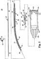
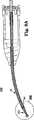
本発明に従った外科用切除器具20の1つの実施の形態が図1及び図2に示される。外科用切除器具20は、外側支持管22と、内側ワイヤー組立体24と、切除先端26と、連結チャック28と、ハウジング30とを有する。構成要素22ないし30については、以下により詳細に説明する。しかし、全体的な表現にて、内側ワイヤー組立体24は外管22内に同軸状に配設される。切除先端26は内側ワイヤー組立体24と接続され且つ、該内側ワイヤー組立体から末端方向に伸びている。連結チャック28は内側ワイヤー組立体24に固定され且つ、モータ(図示せず)の駆動機構(図示せず)と接続し得るようにされる。ハウジング30は、外管22及び連結チャック28を維持し、また、モータと接続し得るようにもされる。この形態の場合、内側ワイヤー組立体24が外管22に対して回転したとき、内側ワイヤー組立体24と外管22との間に軸受が確立される。以下により詳細に説明するように、器具20及びその構成要素は、外管22、従って内側ワイヤー組立体24に対して極めて速い回転速度(80,000RPM以上)を保証し、所望のとき、1つ又はより多くの湾曲部分を画成する1つ又はより多くの造作部を提供する。 One embodiment of a
外管22は、基端42にて終わる基端領域40と、末端46にて終わる末端領域44と、基端領域40と末端領域44との間の中間領域47とを画成する細長い管状体である。更に、外管22は、基端42から末端46まで伸びる管腔48を画成する。このように、外管22の内面50は管腔48を形成する。 The
外管22は、多岐に亙る長手方向形状をとることができるが、中間領域47及び(又は)末端領域44の一方又は双方にて又はこれに沿って少なくとも1つの湾曲部分(全体として図1に参照番号52で表示)を形成することを許容する型式のものであることが好ましい。更に、外管22は、この好ましい湾曲した構造と共に、内側ワイヤー組立体24に対する回転ジャーナル軸受(すなわち摩擦摺動ジャーナル軸受)を形成することを容易にする構造であることが好ましい。最後に、外管22は、ハウジング30のその末端側の実質的な部分に沿って好ましくは2.0mm程度の、最小の最大外径を有する。例えば、図1に示すように、中間領域47は、ハウジング30と当接する増大した直径の肩部54を形成し、中間領域47の残りの部分はハウジング30の末端にて伸びており、また、約2.0mmの均一な直径を有し、また、湾曲部分52と、1つ又はより多くの直線状部分56とを有する。 The
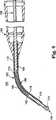
1つの実施の形態において、外管22の外径は、図1に示すように、末端領域44にて末端46までテーパーが付けられている。例えば、1つの実施の形態において、外管22は、約2.0mmの直径から末端46における約1.0mmの直径までテーパーが付けられる。これと代替的に、その他の寸法を採用してもよく、外管22が末端側テーパーを含む必要はない。外管22の長さに依存して、末端領域44の基端側の部分は、僅かにより大きい直径を有することができる。例えば、図3を参照すると、外管22´が40mm以上の長さを有する場合、中間領域47´は3.0mm程度の外径を有することができる一方、末端領域44´は2.0mm程度の外径を有し且つ、直径は末端46´までテーパーが付けられている。 In one embodiment, the outer diameter of the
図1を参照すると、以下に説明するように、内側ワイヤー組立体24は薄い構造とされることが好ましい。この1つの好ましい特徴は、器具20の一部として玉軸受組立体が存在しないことと相俟って、管腔48が相対的に小さい直径を有することを許容し、上述した好ましい最小の外径の場合でさえ、外管22に対して適正な材料が選ばれたとき、外管22は必須の剛直度を提供するのに十分な厚さを有することができる。例えば、外管22の少なくとも一部分が約2.0mmの最大外径を有する1つの実施の形態において、管腔48は、1.0mm以下、より好ましくは0.25ないし1.0mmの範囲、より好ましくは0.5ないし0.8mm、更により好ましくは0.55ないし0.7mmの直径を有する。換言すれば、約2.0mmの最大外径を有するハウジングの末端側の外管22の部分に対して、外管22は、0.3mm以上、好ましくは0.5mm以上、更により好ましくは0.6ないし0.75mmの範囲の肉厚を有する。
Referring to FIG. 1, the
上記のことに鑑みて、1つの実施の形態において、外管22は、好ましい寸法及び曲率の制限を満足させつつ、外管22に対し高強度、高い剛性の特徴を提供するよう選ばれた材料にて出来ている。外管22の剛性は、外管22に対して選ばれた材料及び端部の幾何学的形態の関数である。上述したように、外管22は、湾曲部分52を有することが好ましく、該湾曲部分の形成は、生成される外管22の剛性の特徴に悪影響を与える可能性がある。湾曲した形態(4インチ(10.16cm)、より好ましくは約3インチ(7.62cm)の曲率半径又は20゜ないし30゜の範囲の湾曲角度Aを画成する湾曲部分52のような形態)の場合、外管22は、ハウジング30に対して末端46にて少なくとも15lbf/インチの剛性を示す。重要なことは、この好ましい剛性の特徴は、上述したように最小の最大外径を有する外管22にて実現される。1つの実施の形態において、外管22に対し相対的に小さい外径であるが、増大した肉厚を容易にする好ましい内側ワイヤー組立体24(以下に説明)に鑑みて、外管22は、好ましい剛性及び幾何学的特徴を満足させつつ、ステンレス鋼のような従来の外科用器具の材料にて出来たものとすることができる。
In view of the above, in one embodiment, the
好ましい寸法及び材料の選択に加えて、1つの実施の形態において、外管22の内面50は、以下に説明する好ましい回転ジャーナル軸受の形成を容易にし得るよう顕著に研磨する。より具体的には、外管22の内面50を0.508μm(20μインチ)以下、より好ましくは0.254μm(10μインチ)以下の表面粗さまで研磨することは速い作動速度にて好ましい曲率及び寸法上の特徴を有する外科用切除器具20を具体化するのを容易にすることが驚くべきことに判明した。しかし、これと代替的に、その他の実施の形態において、内面50は顕著に研磨する必要はない。 In addition to selecting preferred dimensions and materials, in one embodiment, the
内側ワイヤー組立体24は、基端部分60と、末端部分62とを有する。内側ワイヤー組立体は、外管22の全体的な長手方向長さよりも長い全体的な長手方向長さを有し、このため、最終的に組み付けたとき、基端部分60及び末端部分62は外管22の端部42、46からそれぞれ伸びている。
内側ワイヤー組立体24は、湾曲した軸方向長さに沿って構造的一体性を維持しつつ、外管22に対する回転ジャーナル軸受の形成を容易にする構造とされることも好ましい。ハウジング30の末端側における外管22の部分が約2.0mmの最小の最大外径を有する1つの好ましい実施の形態と共に、内側ワイヤー組立体24は、0.8mm以下、より好ましくは0.6mm以下、より好ましくは0.5mm程度の減少した直径であることも好ましい。1つの実施の形態において、内側ワイヤー組立体24は、外管の管腔48の直径よりも0.05ないし0.18mm小さい直径を有する。更に、内側ワイヤー組立体24は、高強度及び優れた疲労特性を示すように形成されることが好ましい。疲労強度は、材料の選択と端部の幾何学的形態との関数である。外管22が内側ワイヤー組立体24の長手方向長さに曲率を付与する図1の実施の形態の場合、内側ワイヤー組立体24は、少なくとも517.107MPa(75Kpsi)の疲労強度又は耐久限界値を示すことが好ましい。この好ましい疲労強度特性及び寸法上の制限は、Mシリーズ工具鋼(モリブデン高速度工具鋼)、Aシリーズ工具鋼(中程度合金空気焼入れ冷間加工工具鋼)等のような適正な工具鋼材料にて実現することができる。 The
例えば、1つの実施の形態において、内側ワイヤー組立体24は、均質な単一物ワイヤーM2工具鋼である。これと代替的に、内側ワイヤー組立体24に対して所望の耐久性及び破断抵抗性を示すその他の材料が採用可能であり、これらは、例えば、その他の工具鋼、304Vの高引張り強度の引抜きワイヤー、外面を圧縮状態に置くことによりワイヤーの疲労強度を向上させるロールバニシ仕上げ過程を施したその他のスチールワイヤー材料、外面を圧縮状態に置くことによりワイヤーの疲労強度を向上させるべく超音波ショットピーニング又はレーザショットピーニングを施したその他のスチールワイヤー材料等を含む。更に、炭化ケイ素、窒化ケイ素、炭化ホウ素、炭化チタン、炭化タングステン等のようなセラミックと同様、イリジウム、オスミウム又はルテニウムのようなその他のスチール以外の金属が許容可能である。しかし、これと代替的に、本発明のその他の実施の形態において、上述した強度及び剛直度のパラメータに順応しない従来の材料を採用してもよい。 For example, in one embodiment, the
内側ワイヤー組立体24の摩耗抵抗特性を更に増進させるため、内側ワイヤー組立体24は、加工(例えば、熱処理)を施し且つ(又は)追加的な材料にて被覆し、50HRC以上、より好ましくは60HRC以上のロックウェル硬度となるようにすることが好ましい。例えば、選んだワイヤー材料は、内側ワイヤー組立体24に対し高密度の炭素仕上げを提供する硬化した材料(図1、図2に図示せず)にて被覆されることが好ましい。1つの実施の形態において、硬化した材料による被覆は0.3mm以内の厚さまで被覆した高密度炭素(ダイヤモンド様被覆)である。これと代替的に、例えば、窒化ジルコニウム、クロム、ポリテトラフルオロエチレン(PTFE)又はその他の過フッ化炭化水素材料、窒化チタン、PTFEを含浸させた無電解ニッケル等のようなその他の被覆材料を採用してもよい。 In order to further enhance the wear resistance characteristics of the
外科用切除器具20の組立体について、以下に更に詳細に説明する。しかし、外管22及び内側ワイヤー組立体24の組立体に関して、その間に流体力学的ジャーナル軸受を形成するのを促進し、これにより、流体力学的効果により支えられて、内側ワイヤー組立体24が回転したとき、内側ワイヤー組立体24が外管22に対して効果的に「浮動する」よう、好ましくは2つの構成要素22、24の間の境界面の長さに沿って潤滑剤(図示せず)が提供されることが好ましい。このことに鑑みて、潤滑剤は、40℃にて少なくとも100mm2/秒、より好ましくは、40℃にて150ないし250mm2/秒の範囲の動的粘度を呈し、また、疎水性の性質のグリース潤滑剤であることが好ましい。1つの許容可能なグリース潤滑剤は、例えば、マサチューセッツ州、フェアヘブンのナイ・ルブリカンツ・インク(Nye Lubricants Inc.)からナイ・ニオジェル(Nye NYOGEL)(登録商標名)670として入手可能なシリカにて濃縮した合成炭化水素材料である。これと代替的に、商業的に入手可能なグリースのようなその他の潤滑材料を採用してもよい。The assembly of
切除先端26は、多岐に亙る形態をとることができ、また、切除バー70と、取り付け端部72とを有することが好ましい。取り付け端部72は、内側ワイヤー組立体24の末端部分62を受容する寸法とされた通路74を画成する。この目的のため、例えば、溶接、融接、圧力嵌め、熱シュリンク嵌め、接着剤等のような多数の既知の方法を介して切除先端26を内側ワイヤー組立体24の末端部分62に固定することができる。これと代替的に、内側ワイヤー組立体24及び切除先端26は、内側ワイヤー組立体24及び切除先端26をストック材料の単一物から機械加工する等によって一体的に形成してもよい。しかし、切除バー70は、当該技術にて既知の多岐に亙る形状及び寸法(例えば、2mmの溝付き、1mmの菱形等)をとることができる。 The cutting
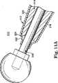
連結チャック28は、多岐に亙る形態をとることができるが、内側ワイヤー24に対するドリルモータの駆動機構(図示せず)の接続を容易にし得るような全体的な形態とされる。1つの参考として、モータ(図示せず)及び駆動機構は多岐に亙る形態をとることができる。モータは、電気、電池作動又は空圧型のような外科用切除器具に対して一般的に採用される型式のものとすることができる。これと代替的に、任意のその他の型式のモータ又はドリル駆動システムを採用してもよい。同様に、駆動機構は、機械的接続、非接触式の磁力接続、非接触式の空気被駆動継手(例えば、空気ベーン)等のような、切除装置への接続又は連結を容易にする、外科用切除器具と共に一般的に採用される型式のものとすることができる。このことに鑑み、図1及び図2の連結チャック28は、機械型式の駆動機構と共に使用し得るようにされるが、これと代替的に、連結チャック28はその他の任意の型式の駆動機構に従った形態としてもよいことが理解される。 The
1つの実施の形態において、連結チャック28は、末端部分80と、基端部分82とにより画成される。末端部分80は、その末端86から伸びる第一の通路84を形成する。第一の通路84は、外管22の基端領域40を緩く受容する寸法とされた直径を画成し、外管22を基端部分82に対して全体として心合わせする作用を果たす。重要なことは、末端部分80が外管22の回りにて回転自在なことである。基端部分82は、第一の通路84から基端方向に伸びる第二の通路87を形成する。第二の通路87は、内側ワイヤー組立体24の基端部分60を受容し且つ該基端部分を維持する寸法とされる。この点に関して、連結チャック28は、締め止め部88のような多岐に亙る技術によって内側ワイヤー組立体24の基端部分60に更に固定することができる。 In one embodiment, the connecting
1つの実施の形態において、基端部分82は、その各々がドリルモータの駆動軸への連結を容易にし得るようにされた溝90及びタング92を形成する。タング92は減少した直径であり、また、駆動機構を連結チャック28に迅速に均一に組み付けることを容易にする案内面として機能する。しかし、この場合にも、連結チャック28は、連結チャック28を外管22及び(又は)内側ワイヤー組立体24に組み付けることができるような、多岐に亙るその他の形態をとることができる。例えば、連結チャック28は、内側ワイヤー組立体24の一体的に形成された部分してもよい。 In one embodiment, the
連結チャック28と同様に、ハウジング30は、多岐に亙る形態をとることが可能であり、また、全体として外管22を支持し且つ、連結チャック28/内側ワイヤー組立体24のモータ(図示せず)への取り付けを容易にする形態とされる。この目的のため、ハウジング30は、外管22上にインサート成形することができる。これと代替的に、接着、溶接、圧力嵌め、熱シュリンク嵌め等のような多岐に亙るその他の組み付け技術が等しく許容可能である。ハウジング30は、モータへの組み付けを容易にする多岐に亙る造作部を有することができる。1つの実施の形態において、ハウジング30は、複数の隔てた指状体104により画成される開放基端102を有する中央開口100を形成する。中央開口100は、モータの少なくとも一部分を受容する寸法とされ、指状体104はモータを開口100内にて拘束する作用を果たす。更に、又はこれと代替的に、ハウジング30は、スナップ嵌め、ねじ、締まり嵌め等を介してドリルモータへの取り付けを容易にする形態としてもよい。更に、図1及び図2の実施の形態の場合、ハウジング30は、開口100と流体的に接続された通路106を画成する。通路106は、外管22を維持する寸法とされ、また、インサート成形過程の間に形成することができる。 Similar to the
外科用切除器具20は、外管22の管腔48内に内側ワイヤー組立体24を同軸状に配設することにより組み付けられる。上述したように、1つの実施の形態において、グリース潤滑剤(図示せず)が内側ワイヤー組立体24と外管22の内面50との間の境界面の少なくとも一部分、好ましくは、その全体に亙って配設される。外管22は、図1に示すように、ハウジング30に組み付けられ、中間領域47及び末端領域44がハウジング30の末端側に伸びている。上述したように、ハウジング30は外管22の上でインサート成形し、その後、内側ワイヤー組立体24を管腔48内に配置することができる。更に、中間領域47は、ハウジング30に対向するように配置する停止面を提供する肩部54を有することができる。
1つの実施の形態において、材料の選択及び生成する軸受のような外科用切除器具20の色々な好ましい設計上の特徴は、図1にBにて示した、外管22の末端46の末端側にて内側ワイヤー組立体24を僅かな程度、露出させることを許容する。例えば、内側ワイヤー組立体24の露出長さBは、2.54mm(0.1インチ)以下、より好ましくは1.3mm(0.05インチ)以下であることが好ましい。しかし、連結チャック28は、内側ワイヤー組立体24の基端部分60に固定される一方、切除先端26は末端部分62に取り付けられる。 In one embodiment, various preferred design features of the
上述したように、外管22は、少なくとも1つの湾曲部分52を有することが好ましい。内側ワイヤー組立体24を外管22内に配置したとき、内側ワイヤー組立体24は外管22の形状、従って湾曲部分52の形状をとる。このことに鑑みて、外管22/内側ワイヤー組立体24は、1つ又はより多数の湾曲部分(湾曲部分52のような)と、図1に示した真っ直ぐな部分56のような1つ又はより多数の真っ直ぐな部分とを含む、多岐に亙る長手方向形状をとることができる。例えば、図4には、外管22´´(従って(図示しない)内側ワイヤー組立体)が2つの湾曲部分110、112を有する代替的な実施の形態の切除器具20´´が示される。これと代替的に、外管22、22´´(従って、内側ワイヤー組立体24)が真っ直ぐであるようにしてもよい。しかし、真っ直ぐな部分及び(又は)湾曲部分の寸法は、特定の医学方法の必要性に適合するよう最適化され、曲率半径(又は複数の半径)は、内側ワイヤー組立体24(図1)がその弾性限界内にて変形するのを保証するのに十分に大きい。 As described above, the
この場合にも、図1の1つの好ましい実施の形態のとき、湾曲部分52は、約25°の偏心角度Aとなる、約7.6cm(3インチ)の曲率半径を画成する。外管22、内側ワイヤー組立体24及び潤滑剤に対する上述した好ましい寸法及び材料の選択は、以下に説明するように、高速度、長期間の作動が可能なこの1つの好ましい曲率の特徴を許容することが驚くべきことに判明した。 Again, in one preferred embodiment of FIG. 1, the
図1を再度参照すると、使用中、モータ(図示せず)は、ハウジング30と接続され、駆動機構(図示せず)は連結チャック28と接続される。その後、モータを作動させ、連結チャック28、従って内側ワイヤー組立体24を回転させる。1つの実施の形態において、内側ワイヤー組立体24が外管22に対して回転する結果、ハウジング30の末端側にて、外管22の長さの少なくとも一部分又は好ましくは、その全体に沿って内側ワイヤー組立体24と外管22の内面50との間に回転ジャーナル軸受が形成される。更により好ましい実施の形態において、上述したグリース潤滑剤は、内側ワイヤー組立体24が回転したとき、内側ワイヤー組立体24と外管22の内面50との間に流体力学的ジャーナル軸受及び(又は)組み合わせた回転及び流体力学的ジャーナル軸受が形成される。しかし、外科用切除器具20は、外管22と内側ワイヤー組立体24との間に玉軸受組立体を備えていない。
Referring back to FIG. 1, in use, the motor (not shown) is connected to the
本発明の外科用切除器具20は、速い回転速度のときその構造的一体性を保つことができる。例えば、外科用切除器具20は、50,000RPM以上の回転速度にて作動可能である。更に、1つの好ましい実施の形態において、内側ワイヤー組立体24がM2工具鋼にて形成される場合、外管22の内面50は、顕著に研磨して、グリース潤滑剤を内側ワイヤー組立体24と外管22の内面50との間に配設した場合、外管22/内側ワイヤー組立体24は、長期間の一体性及び最小の熱蓄積を有する流体力学的回転ジャーナル軸受にて80,000RPMの公称回転切除速度を提供しつつ、約25°の変位角度A及びその実質的な部分に沿って約2.0mmの最大外径を提供する湾曲部分52を含むことが可能であることが驚くべきことに判明した。このように、生成する外科用切除器具20は、外管22/内側ワイヤー組立体24の小さい外径の湾曲した性質を介して外科医に対する視覚性の妨害が最小状態にて高速度の外科的切除方法を容易にする。 The
発熱が最小限であることは、内側ワイヤー組立体24の最小の露出長さBの場合と同様に、外科用切除器具20を実質的に全ての外科的用途にて極めて安全なものにする。更に、外管22は極めて剛直であるから、外科的方法を実行する間、取り扱い及び使用を大幅に促進する。上述した性能の特性は、内側ワイヤー組立体24における硬化した材料被覆(例えば、ダイヤモンド様被覆)にて更に向上させることができる。上述した特徴(例えば、材料の選択、加工、潤滑剤の選択)の各々は、価値ある高速度のロープロファイルの湾曲した外科用切除器具を製造するとき、相乗的効果を有する一方にて、これらの特徴の1つ又はより多数の変更例を採用することができ、これらは本発明の範囲に属するものである。 Minimal fever, as with the minimum exposed length B of the
1つの代替的な実施の形態の外科用切除器具120は図5に示される。外科用切除器具120は、上述した外科用切除器具20(図1)と同様であり、また、外管122と、内側ワイヤー組立体124と、切除先端126と、連結チャック128と、ハウジング130とを有する。外管122、切除先端126、連結チャック128及びハウジング130は、上述した切除器具20(図1)の相応する構成要素と同様であることが好ましい。内側ワイヤー組立体124については以下により詳細に説明する。しかし、全体的な説明にて、内側ワイヤー組立体124は、外管122により画成された管腔134内に同軸状に配設され、外管122は湾曲部分136を形成する。最終的に組み付けて且つ作動させたとき、回転ジャーナル軸受、好ましくは、流体力学的回転ジャーナル軸受(グリース潤滑剤(図示せず)が採用される場合)が内側ワイヤー組立体124と外管122との間に確立され、器具120は、80,000RPM以上の公称切除速度が可能である。 One alternative embodiment
内側ワイヤー組立体124は、基端部分140と、中間部分142と、末端部分144とを有する。中間部分142は、その両端にて基端部分140及び末端部分144とそれぞれ接続される。この点に関して、基端部分140及び末端部分144は、高強度ワイヤー又は管である。1つの好ましい実施の形態において、基端部分140及び末端部分144に対して選ばれた材料は、内側ワイヤー組立体24(図1)に関して説明したものと同様であることが好ましい。これと逆に、中間部分142は可撓性の多数撚りワイヤーコイルである。可撓性の巻いたコイルの形態は、容易に湾曲した形状をとり、また、レーザ溶接又は焼結のような多岐に亙る方法にて基端部分140及び末端部分144に取り付けることができる。
中間部分142、基端部分140及び末端部分144の長さ及び位置は、外管122の形状の関数である。例えば、図5に示すように、内側ワイヤー組立体124は、最終的に組み付けたとき、中間部分142が湾曲部分136内に配設されるような構造とする。望ましくは、外管122が2つ又はより多数の湾曲部分を画成する場合、可撓性の巻いたワイヤーコイルの相応する数の中間部分を内側ワイヤー組立体124内に組み込むことができる。別の実施の形態において、基端部分140、中間部分142及び(又は)末端部分144の1つ又はより多数には、上述したように硬化した被覆が施される。同様に、別の実施の形態において、上述したようなグリース潤滑剤が内側ワイヤー組立体124/外管122の境界面に沿って配設される。しかし、中間部分142を可撓性に巻いたコイルとして形成することにより、中間部分142は、相対的に小さい曲率半径を維持し、外科用切除器具120を多岐に亙る異なる外科的方法に適用し得るようにすることができる。 The length and position of the
更に別の代替的な実施の形態の外科用切除器具150は図6に示される。該切除器具150は、上述した実施の形態と同様であり、また、外管152と、内側ワイヤー組立体154と、切除先端156と、連結チャック158と、ハウジング160とを有する。この場合にも、内側ワイヤー組立体154は、その他の点にて湾曲部分164を含む外管152により形成された管腔162内に同軸状に配設される。1つの好ましい実施の形態において、中間管166は湾曲部分164に沿って外管152と内側ワイヤー組立体154との間に配設される。 Yet another alternative embodiment
外管152は、連結チャック158、及びハウジング160のような、外管22(図1)に関して上述した形態の任意のものをとることができる。内側ワイヤー組立体154は第一の部分170と、第二の部分172とを有する。第一の部分170は、連結チャック158が固定され又は一体的に形成される剛直な軸又はワイヤーである。第二の部分172は、第一の部分170から末端方向に伸び且つ、上述した内側ワイヤー組立体24(図1)と類似したばねワイヤーである。すなわち、第二の部分172は、内側ワイヤー組立体24に関して上述した形態の任意のものをとることができる。第一の部分170及び第二の部分172は、別個に形成し且つ、互いに締結し(例えば、レーザ溶接、焼結等により)又はストック材料の単一物から一体的に形成してもよい。しかし、第二の部分172は、第一の部分170の直径よりも小さい直径を画成し、外管152の湾曲部分164の円弧状長さと相応的な軸方向長さを有する。
1つの実施の形態において、切除先端156は、切除バー174と、軸176とを有する。軸176は、切除バー174から末端方向に伸び且つ、内側ワイヤー組立体154の第二の部分172に取り付けられる。これと代替的に、軸176は、内側ワイヤー組立体154の一部として形成し、その後、切除バー174を取り付けてもよい。例えば、軸176は、第一の部分170と同一の構造とすることができる。更に、切除先端156及び内側ワイヤー組立体154は一体的に形成することができる。しかし、第二の部分172は軸176の直径よりも小さい直径を有する。 In one embodiment, the cutting
望ましいことに、第二の部分172は切除バー174により誘発された曲げ荷重を支持する必要がないから、第二の部分172の直径を第一の部分170及び軸176の直径よりも小さくすることができる。このことは、湾曲部分164(最終的に組み付けたとき、この湾曲部分に沿って第二の部分172が静止する)の半径を減少させることを許容し、また、湾曲部分164内の摩擦荷重/熱を減少させる。 Desirably, the diameter of the
1つの実施の形態において、内側ワイヤー組立体154が回転したとき、第二の部分172を支持するため、第二の部分172と外管152との間に中間管166が提供される。1つの実施の形態において、中間管166は、PTFE材料にて形成されるが、これと代替的に、その他の可撓性の管材料を採用してもよい。 In one embodiment, an
使用中、外科用切除器具150は、上述の実施の形態と極めて同様の要領にて作動する。特に、モータ(図示せず)は、内側ワイヤー組立体154を外管152に対して回転させ、内側ワイヤー組立体154の少なくとも一部分と外管152の内面178との間にて回転するジャーナル軸受が形成されるようにする。1つの好ましい実施の形態において、例えば、第一の部分170及び(又は)切除先端156の軸176に沿った内側ワイヤー組立体154の部分と外管152の部分との間にグリース又はその他の潤滑剤が配設され、高回転速度時、流体軸受が外管152に沿って確立されるようにする。上述した実施の形態と同様に、この場合、外科用切除器具150は、ロープロファイルの湾曲した外管152の組立体に対し80,000RPM公称回転速度を提供し得るようにされる。 In use,
上述した外科用切除器具20(図1)、120(図5)、150(図6)の各々は、ターゲット箇所の灌注を行い得るようにすることができる。例えば、図7には、灌注管192と共に、図1の切除器具20を含む、代替的な実施の形態の外科用切除器具190が示される。灌注管192は、溶接、接着等によってハウジング30及び外管22に固定される。この形態の場合、灌注管192は、その基端にて流体源(図示せず)と流体的に接続されており、このため、切除先端26を灌注し、これにより別個の灌注装置を不要にする。更に、流体が灌注管192を通って流れる状態にて熱を外管22から除去し、これにより、内側ワイヤー組立体24が長期間に亙って高速度にて回転するのを容易にする。 Each of the surgical excision instruments 20 (FIG. 1), 120 (FIG. 5), and 150 (FIG. 6) described above can be capable of irrigating a target site. For example, FIG. 7 shows an alternative embodiment
上述した灌注管192の1つの代替例として、図8には、内部灌注を行い得るようにされた更に別の代替的な実施の形態の外科用切除器具200が示される。外科用切除器具200は、外管202と、内部連結組立体204と、切除先端206と、連結チャック208と、ハウジング210とを有する。外管202、連結チャック208及びハウジング210は、それ以前の実施の形態と極めて類似している。しかし、内部連結組立体204は、外管202の管腔212内に同軸状に受容し得る寸法とされた管状部材である。 As one alternative to the
内部連結組立体/管状部材204は、基端部分218と、中間部分220と、基端部分222を有する。中間部分220が可撓性であり、従って湾曲した形態を均一に形成し且つ、維持することを許容するらせん状レーザ切り込みパターン(全体として、参照番号224にて表示)が中間部分220に沿って形成される。このように、最終的に組み付けたとき、中間部分220は、外管202の長手方向に湾曲した部分230の形状に適合する。内部連結組立体204に対して選ばれる材料は、内側ワイヤー組立体24(図1)に関して上述したものと同様であることが好ましい。しかし、内部連結組立体204の外径は、外管202/管腔212の内径よりも小さい。内部連結組立体204と外管202との間の直径方向空隙は、外管202を通して灌注流体(図示せず)を送り出すのを許容する。この構造によれば、切除先端206は、内部連結組立体204内に受容し得る寸法とされた軸232を有することが好ましい。これと代替的に、切除先端206を内部連結組立体204に対して組み付けるその他の技術も等しく許容可能である。 The inner coupling assembly /
追加的な密封造作部を上述した外科用切除器具の1つ又はより多数に組み込み、外管内に入り又は外管から出る材料の流れを最小にすることができる。例えば、図9Aは、図1の外科用切除器具20と類似し且つ、密封先端252を更に有する1つの代替的な実施の形態による外科用切除器具250の側面断面図である。特に、密封先端252は、外管22の末端領域44に取り付けられ且つ、該末端領域44から末端方向に伸び、また、軸受/密封面を提供し、該軸受/密封面は、内側ワイヤー組立体24の外径に一層正確に近似し、これにより、外科手術箇所への材料の摂取及び(又は)外科手術箇所への材料の解放を制限する。 Additional sealing features can be incorporated into one or more of the surgical resection instruments described above to minimize material flow into or out of the outer tube. For example, FIG. 9A is a side cross-sectional view of a
密封先端252は、セラミック材料、好ましくはサファイアにて出来ており、外管22と比較して増大した硬度及び表面仕上げを示す。このように、密封先端252は、密封先端252と内側ワイヤー組立体24との間に形成された軸受の寿命を延ばす向上した耐磨耗特性を有する。更に、セラミック材料は、スチール(その他の点にて、外管22に対して使用されることが好ましい)と比較して、正確な許容公差の条件に合わせて容易に製造し、密封先端252の内側管腔254が外管22の管腔48の直径よりも小さい直径を有し、その結果、内側ワイヤー組立体24に比して減少した直径方向隙間となるようにすることができる。一方、この減少した隙間は、材料が外管22に入り且つ(又は)外管22から出るのを更に防止することになる。例えば、1つの実施の形態において、密封先端252の管腔254は、内側ワイヤー組立体24に対し、0.005ないし0.01mmの範囲の直径方向隙間を提供するよう製造することができる。 The sealing
密封先端252は、多岐に亙る要領にて外管22に組み付けることができる。図9Bの1つの実施の形態において、外管22は、緊密滑り嵌めを介して密封先端252の外径部を受容し得るようにされた直径を有する内部開口又は端ぐり穴256をその末端46に形成する。この形態によれば、接着剤又は保持コンパウンド(図示せず)が密封先端252を外管22に固定する。しかし、密封先端252及び(又は)外管22は、密封先端252の直径の少なくとも1.5倍の長手方向境界面長さを提供し、四角及び真っ直ぐさを維持する。密封先端252は長手方向に真っ直ぐであるため、全長は、湾曲した外管22と共に採用されたとき、相対的に短いことが好ましい。十分な軸受面を提供するため、密封先端252は、1つの実施の形態において、5.3ないし7.3mm、より好ましくは6.35mm程度の長さを有する。最後に、密封先端252は、外管22の外径と一致し、好ましくは該外径よりも小さい外径を有し且つ、末端テーパー付き部分258を形成することが好ましい。例えば、1つの実施の形態において、密封先端252は、外径にて約0.5ないし1.5mmのテーパーが付けられる。 The sealing
図10には、代替的な密封先端282を有する別の代替的な実施の形態の外科用切除器具280の一部分が示される。外科用切除器具280は、上述した実施の形態の任意のものに従った形態とすることができ、また、外管284と、内側ワイヤー組立体286とを有しており、これらは図10の1つの実施の形態の場合、図1の外科用切除器具20の相応する要素と同様である。図面の便宜上、外管284と内側ワイヤー組立体286との間の隙間は、図10にて著しく誇張されており、切除先端26(図1)は図示していない。このことに鑑み、密封先端282は、外管284の末端領域288に組み付けられ且つ、基端部分290と、中間部分292と、末端部分294とを有する。1つの実施の形態において、密封先端282は、一体的本体としてポリテトラフルオロエチレン(PTFE)のような硬化し、しかも弾性的な材料から機械加工される。基端部分290は、外管284により形成された半径方向溝298内に拘束し得る寸法とされたフランジ296を形成することが好ましい。 FIG. 10 shows a portion of another alternative embodiment
これと代替的に、密封先端282を外管284に取り付けるその他の技術を採用してもよい。中間部分292は、密封先端282の末端側の物を視認する妨害程度を最小にし得るよう、基端部分290と比較して減少した外径を有することが好ましい。しかし、末端部分294は、中間部分292から末端300まで内方に湾曲し又は曲がっている。特に、末端300は、内側ワイヤー組立体286の外径よりも小さい外径を画成し、最終的に組み付けたとき、末端300が内側ワイヤー組立体286に対し偏倚され且つ、該内側ワイヤー組立体286により拡張されるようにする。この形態によれば、末端300は、内側ワイヤー組立体286に対するシールを効果的に形成する。 Alternatively, other techniques for attaching the sealed
更に別の代替的な密封組立体が図11Aに示される。特に、図11Aには、密封先端312を含む代替的な実施の形態の外科用切除器具310の一部分が示される。この場合にも、密封先端312は、上述した任意の切除器具と共に使用することができ、また、図11Aの実施の形態の場合、外管314と、内側ワイヤー組立体316とを有し、これらは、図1の外科用切除器具20に関して説明したものと同様である(外管314と内側ワイヤー組立体316との間の隙間は図11Aの図にて著しく誇張して示してある)。このことに鑑み、密封先端312は、外管314の末端領域318に固定され且つ、基端部分320と、末端部分322とを有する。1つの実施の形態において、密封先端312は、PTFEシュリンク管のようなシュリンク管材料にて一体的に形成される。しかし、基端部分320は、外管314上に同軸状に受容され、このため、末端部分322は、外管314の末端324から末端側に伸びている。その後、密封先端312に対しシュリンク工程を行い(例えば、加熱する)、その結果、図11Aの形態となる。 Yet another alternative sealing assembly is shown in FIG. 11A. In particular, FIG. 11A shows a portion of an alternative embodiment
より具体的には、密封先端312はシュリンクされ、基端部分320は外管314の相応する部分に適合する。更に、末端部分322の少なくとも一部分は、内側ワイヤー組立体316上に且つ、該内側ワイヤー組立体316に対してシュリンクし、その間にシールを形成する。1つの好ましい実施の形体において、密封先端312は極めて薄く(0.125mm程度)、また、外管314の末端324に対して、0.5mm程度の最小の末端方向距離を有する。これと代替的に、その他の寸法を採用してもよい。 More specifically, the sealed
図11Bには、密封先端312を取り付ける1つの代替的な技術が示される。特に、1つの代替的な外管330が提供され、その末端領域332は、半径方向肩部334と、フランジ336とを形成する。密封先端312は、外管330の末端領域332上に組み付けられ、基端338が肩部334と当接するようにする。次に、密封先端312に対しシュリンク工程を行い、その結果、図11Bの形態となる。肩部334は、密封先端312の末端部分322が外管330の末端側に伸び且つ、内側ワイヤー組立体316と係合するのを保証する。更に、フランジ336は、密封先端312を外管330に対して効果的に係止し、密封先端312が外管330に対し長手方向に動かないようにする。 In FIG. 11B, one alternative technique for attaching the sealing
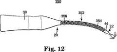
上述した外科用切除器具又は特に説明しない実施の形態の1つ又はより多数に対して、連続的な高速度の作動中、熱の蓄積を更に最小にする追加的な造作部を組み込むことができる。例えば、図12には、蒸発冷却スリーブ352と共に、図1の切除器具20を含む別の代替的な実施の形態の外科用切除器具350が示される。望ましいことに、本明細書に記載したその他の外科用切除器具の実施の形態の任意のものと共に、蒸発冷却スリーブ352を採用することができる。図12の1つの実施の形態を参照すると、冷却スリーブ352は、ハウジング30から末端領域44まで伸びることが好ましい外管22の外側を亙って固定される。冷却スリーブ352は、ナイロン、シルク、ポリプロピレン、ポリエステル、綿等のような繊維材料にて形成されることが好ましく、また、好ましくは、非被覆ナイロンであるものとする。しかし、冷却スリーブ352は、外管22により画成された任意の湾曲部分に容易に順応し、外管22に直接巻かれた編組管又は糸のコイルの構造としてもよい。 Additional features that further minimize heat build-up during continuous high speed operation can be incorporated into one or more of the surgical resection instruments described above or in particular embodiments not specifically described. . For example, FIG. 12 shows another alternative embodiment
1つの実施の形態において、冷却スリーブ352の両端は、締め止め又は接着剤により外管22に固定される。冷却スリーブ352は、流体(例えば、手術箇所における体液、外科手術中に送り出された灌注流体等)、好ましくはその吸収した流体をハウジング30に向けて吸上げるような構造とされる。すなわち、流体が冷却スリーブ352の末端領域354にて吸収されるとき、そのようにして吸収された流体は、冷却スリーブ352の全体が飽和される迄、基端領域356に向けて移送され又は伝達される。冷却スリーブ352は、外管22の実質的な長さに沿って伸びるものとして図12に示されるが、代替的な実施の形態において、冷却スリーブ352はハウジング30まで伸びる必要はない。これとは逆に、冷却スリーブ352は、代替的に外管22の全体を取り囲むような構造及び寸法としてもよい。 In one embodiment, both ends of the
使用中、冷却スリーブ352により吸収された流体は、内側ワイヤー組立体24(図2)が外管22に対して回転することで発生された熱を介して蒸発し、外管22を冷却する作用を果たす。この構造によれば、外管22がより多くの熱を伝導すると、冷却スリーブ352により促進される蒸発過程は、より強力となり、その結果、外管22の表面温度を相対的に一定のレベルに調節する。例えば、外管22の温度にも拘らず、本発明の冷却スリーブ352は、流体が存在するとき、外管22を実質的に公称温度(10℃以内)まで冷却することになろうことが判明した。しかし、好ましくは、流体を外科手術箇所から少なくとも部分的に除去すると共に、向上した冷却効果が提供される。 During use, the fluid absorbed by the
本発明の外科用切除器具は、従来の設計に優る顕著な改良点を提供する。好ましい材料の選択及び加工技術と共に、玉軸受組立体を不要にすることにより、外側支持管は、必須の剛性を提供しつつ、最適な配置及び寸法とされた湾曲部分と共に、その他の利用可能な外科用器具よりも著しく小さい外径を有することが可能である。更に、好ましい材料の選択、また、所望であるとき、潤滑剤は、器具の磨耗及び熱の蓄積が最小状態にて長期間の高速度回転(80,000RPM程度)を許容する。最後に、本発明の外科用切除器具は、必要な構成要素の数が最小で済み、これにより、コスト及び組み付け時間を削減するものである。
The surgical resection instrument of the present invention provides significant improvements over conventional designs. By eliminating the need forball bearing assemblies, along with preferred material selection and processing techniques, the outer support tube can be used with curved sections that are optimally positioned and dimensioned while providing the requiredrigidity. It is possible to have a significantly smaller outer diameter than the surgical instrument. Furthermore, the choice of preferred materials and, if desired, the lubricant allows long-term high speed rotation (on the order of 80,000 RPM) with minimal wear and heat build-up of the equipment. Finally, the surgical ablation instrument of the present invention requires a minimum number of components, thereby reducing cost and assembly time.
好ましい高速度、湾曲したロープロファイルの特徴のため、本発明の外科用切除器具は、多岐に亙る用途にて使用することが可能である。1つの可能な適用分野は、その幾つかを挙げれば、人工内耳植え込み術、蝸牛形成術、鼓室形成術、耳小骨連鎖再建術、聴神経腫外科手術(例えば、中間及び後方窩アプローチ法)、錐体尖嚢胞の排液術及び乳突削開術のような多数の神経耳鼻科手術を含む。更に、本発明の外科用切除器具は、洞外科手術、脊椎の骨棘の除去術、身体全体に亙る関節炎骨棘の除去術、脊椎板外科手術、膝の外科手術、腰の外科手術、整形外科手術等のような多岐に亙るその他の身体の処置法のため使用することができる。 Because of the preferred high speed, curved low profile features, the surgical resection instrument of the present invention can be used in a wide variety of applications. One possible field of application is, for example, cochlear implants, cochleoplasty, tympanoplasty, ossicular chain reconstruction, acoustic neuroma surgery (eg, middle and posterior fossa approaches), cones Includes a number of neuro-otolaryngological operations such as drainage of the apical cysts and mastectomy. Further, the surgical excision instrument of the present invention includes sinus surgery, spinal spine removal, arthritic osteophyte removal throughout the body, spinal disc surgery, knee surgery, hip surgery, orthopedic surgery. It can be used for a wide variety of other body treatments such as surgery.
例えば、外科用切除器具20(図1)は、蝸牛形成手術を行うため使用することができる。この外科手術の主たる目的は、受信機−刺激器のパッケージ体を頭蓋の側頭骨内に定着させ且つ、電極列を蝸牛内に挿入することである。本発明の1つの実施の形態に従い、蝸牛形成術を行うべき耳の後方の皮膚を頭蓋から持ち上げて側頭骨を露出させる。外科用ドリルを使用して乳様突起の大きい部分を除去する(デバルクする)。所望であれば、重要な身体部分に接近したとき、より小さい切除先端を採用して顔の凹所に到達する迄、乳様突起を切開する。しかし、この時点にて、湾曲形態であり且つ、2mmの切除先端を有することが好ましい本発明の高速度の外科用切除器具を配設し且つ、作動させ(すなわち、少なくとも50,000RPMの速度にて)、骨を顔凹所を通して切開する。顔神経は顔凹所の側部に沿って伸びるため、これは、重要な部分である。 For example, the surgical resection instrument 20 (FIG. 1) can be used to perform cochlear plastic surgery. The main purpose of this surgery is to fix the receiver-stimulator package in the temporal bone of the skull and to insert the electrode array into the cochlea. In accordance with one embodiment of the present invention, the skin behind the ear to be cochleoplasty is lifted off the skull to expose the temporal bone. Use a surgical drill to remove (debulk) large parts of the mastoid process. If desired, the mastoid is incised when a critical body part is approached until a smaller cutting tip is employed to reach the facial recess. However, at this point, the high speed surgical resection instrument of the present invention that is curved and preferably has a 2 mm resection tip is deployed and activated (ie, at a speed of at least 50,000 RPM). And incising the bone through the facial recess. This is an important part because the facial nerve extends along the sides of the facial recess.
この目的のため、湾曲形態を有する本発明の外科用切除器具は、外管が顔凹所内に伸びるとき、顔神経を保護し、これにより、さもなければ、予期せずに顔神経に接触し且つ(又は)熱損傷を生じさせるであろう回転内側ワイヤーへの顔神経の露出を最小にする。更に、本発明の外科用切除器具の湾曲した最小外径の好ましい造作部は、従来の切除器具と比較して、外科医に対し手術箇所への著しく改良された視覚性を提供する。中耳腔に達したならば、蝸牛内に小さい穴を穿孔するため、2mmの切除先端を1.0mm又は0.5mmの切除先端と置換することができる。しかし、本発明の外科用切除器具と関係した改良された視覚性は、穴を正確な位置にて形成することを保証するのを助ける。次に、電極列を蝸牛内に挿入し且つ、傷口を閉じる。 For this purpose, the surgical resection instrument of the present invention having a curved configuration protects the facial nerve when the outer tube extends into the facial recess, thereby otherwise contacting the facial nerve unexpectedly. And / or minimize exposure of the facial nerve to the rotating inner wire that would cause thermal damage. Moreover, the preferred feature of the curved minimum outer diameter of the surgical resection instrument of the present invention provides the surgeon with significantly improved visibility to the surgical site compared to conventional resection instruments. Once the middle ear cavity is reached, the 2 mm excision tip can be replaced with a 1.0 mm or 0.5 mm excision tip to drill a small hole in the cochlea. However, the improved visibility associated with the surgical cutting instrument of the present invention helps to ensure that the hole is formed in the correct location. Next, the electrode array is inserted into the cochlea and the wound is closed.
上述した外科手術法は、本発明の外科用切除器具を使用する例の単に一例にしか過ぎない。この場合にも、外科用切除器具は、多数のその他の外科手術を容易にする。より一般的な表現にて且つ、1つの好ましい実施の形態に従い、外科用切除器具は、湾曲形態にて提供され、ターゲット箇所の骨のような露出した組織に対して配設し、50,000RPM以上の速度にて作動させて接触した組織を除去する(例えば、切除、穿孔、切開等により)。本発明は、好ましい実施の形態に関して説明し たが、当該技術の当業者は、本発明の精神及び範囲から逸脱せずに、形態及び細部の点にて変更を加えることが可能であることが理解されよう。 The surgical procedure described above is merely one example of using the surgical resection instrument of the present invention. Again, the surgical resection instrument facilitates a number of other surgical procedures. In more general terms and in accordance with one preferred embodiment, the surgical resection instrument is provided in a curved configuration and is placed against exposed tissue, such as bone at the target location, at 50,000 RPM. Operate at the above speed to remove the contacted tissue (eg, by excision, perforation, incision, etc.). Although the present invention has been described in terms of a preferred embodiment, those skilled in the art can make changes in form and detail without departing from the spirit and scope of the invention. It will be understood.
Claims (58)
Translated fromJapanese第一の湾曲部分と、基端にて終わる基端領域と、末端にて終わる末端領域と、基端から末端まで伸びる管腔とを画成する外管であって、該管腔が該外管の内面により画成される外管と、
前記管腔内に受容され1つのワイヤーを有する内側ワイヤー組立体であって、基端部分と、末端部分とを有し、基端部分は外管の基端から基端方向に伸びる内側ワイヤー組立体と、
前記内側ワイヤー組立体の末端部分と接続され、その少なくとも一部分が外管の末端の末端側に伸びる切除先端と、
前記内側ワイヤー組立体の基端部分に固定され、モータの駆動機構と接続し得るようにされた連結チャックと、
前記外管の基端領域及び連結チャックを維持し、モータと接続し得るようにされたハウジングと、を備え、
前記内側ワイヤー組立体が外管に対して回転したとき、内側ワイヤー組立体の外面とハウジングの末端側における外管の内面の全長部分との間に回転ジャーナル軸受が確立され、
最終的に組み付けたとき、前記ワイヤーは前記第一の湾曲部分の形状をとり、
前記外科用切除器具は、前記内側ワイヤー組立体が50,000RPM以上の速度にて前記外管に対して回転することを許容するよう構成されている、外科用切除器具。A surgical excision instrument for use with a motor having a drive mechanism,
An outer tube defining afirst curved portion, a proximal region ending at the proximal end, a distal region ending at the distal end, and a lumen extending from the proximal end to the distal end, the lumen being the outer tube An outer tube defined by the inner surface of the tube;
An inner wire assemblyhaving one wire received in the lumen, the inner wire assemblyhaving a proximal end portion and a distal end portion, the proximal end portion extending in the proximal direction from the proximal end of the outer tube Solid,
A cutting tip connected to a distal portion of the inner wire assembly, at least a portion of which extends toward the distal end of the distal end of the outer tube;
A coupling chuck fixed to a proximal end portion of the inner wire assembly and adapted to be connected to a drive mechanism of a motor;
A housing adapted to maintain a proximal end region of the outer tube and a coupling chuck and to be connected to a motor;
When the inner wire assembly is rotated relative to the outer tube, a rotating journal bearing is established between the outer surface of the inner wire assembly and theentire length of the inner surface of the outer tube on the distal side of the housing,
When finally assembled, the wire takes the shape of the first curved portion,
The surgical resection instrument is configured to allow the inner wire assembly to rotate relative to the outer tube at a speed of 50,000 RPM or greater .
前記外管の末端領域と接続され、その少なくとも一部分が外管の管腔の直径よりも小さい内径を画成する密封先端を更に備える、外科用切除器具。The surgical excision instrument according to claim 1, comprising:
A surgical resection instrument further comprising a sealed tip connected to a distal region of the outer tube, at least a portion of which defines an inner diameter that is smaller than the diameter of the lumen of the outer tube.
外管の少なくとも一部分上に配設された冷却スリーブを更に備える、外科用切除器具。The surgical excision instrument according to claim 1, comprising:
The surgical ablation instrument further comprising a cooling sleeve disposed on at least a portion of the outer tube.
第一の湾曲部分と、基端にて終わる基端領域と、末端にて終わる末端領域と、基端から末端まで伸びる管腔とを画成する外管であって、該管腔が該外管の内面により画成される外管と、An outer tube defining a first curved portion, a proximal region ending at the proximal end, a distal region ending at the distal end, and a lumen extending from the proximal end to the distal end, the lumen being the outer tube An outer tube defined by the inner surface of the tube;
前記管腔内に受容され1つのワイヤーを有する内側ワイヤー組立体であって、基端部分と、末端部分とを有し、基端部分は外管の基端から基端方向に伸びる内側ワイヤー組立体と、An inner wire assembly having one wire received in the lumen, the inner wire assembly having a proximal end portion and a distal end portion, the proximal end portion extending in the proximal direction from the proximal end of the outer tube Solid,
前記内側ワイヤー組立体の末端部分と接続され、その少なくとも一部分が外管の末端の末端側に伸びる切除先端と、A cutting tip connected to a distal portion of the inner wire assembly, at least a portion of which extends toward the distal end of the distal end of the outer tube;
前記内側ワイヤー組立体の基端部分に固定され、モータの駆動機構と接続し得るようにされた連結チャックと、A coupling chuck fixed to a proximal end portion of the inner wire assembly and adapted to be connected to a drive mechanism of a motor;
前記外管の基端領域及び連結チャックを維持し、モータと接続し得るようにされたハウジングと、を備え、A housing adapted to maintain a proximal end region of the outer tube and a coupling chuck and to be connected to a motor;
前記内側ワイヤー組立体が外管に対して回転したとき、内側ワイヤー組立体の外面とハウジングの末端側における外管の内面の全長部分との間に回転ジャーナル軸受が確立され、When the inner wire assembly is rotated relative to the outer tube, a rotating journal bearing is established between the outer surface of the inner wire assembly and the entire length of the inner surface of the outer tube on the distal side of the housing,
最終的に組み付けたとき、前記ワイヤーは前記第一の湾曲部分の形状をとり、When finally assembled, the wire takes the shape of the first curved portion,
前記外科用切除器具は、軸受の破損を伴なわずに、前記内側ワイヤー組立体が80,000RPMの速度にて前記外管に対して回転することを許容するよう構成されている、外科用切除器具。The surgical resection instrument is configured to allow the inner wire assembly to rotate relative to the outer tube at a speed of 80,000 RPM without bearing failure. Instruments.
前記外管の末端領域と接続され、その少なくとも一部分が外管の管腔の直径よりも小さい内径を画成する密封先端を更に備える、外科用切除器具。A surgical excision instrument further comprising a sealed tip connected to a distal region of the outer tube, at least a portion of which defines an inner diameter that is smaller than the diameter of the lumen of the outer tube.
外管の少なくとも一部分上に配設された冷却スリーブを更に備える、外科用切除器具。The surgical ablation instrument further comprising a cooling sleeve disposed on at least a portion of the outer tube.
Applications Claiming Priority (2)
| Application Number | Priority Date | Filing Date | Title |
|---|---|---|---|
| US10/776,835US7488322B2 (en) | 2004-02-11 | 2004-02-11 | High speed surgical cutting instrument |
| PCT/US2005/002879WO2005077284A2 (en) | 2004-02-11 | 2005-02-01 | High speed surgical cutting instrument |
Publications (3)
| Publication Number | Publication Date |
|---|---|
| JP2007521916A JP2007521916A (en) | 2007-08-09 |
| JP2007521916A5 JP2007521916A5 (en) | 2010-06-17 |
| JP4538010B2true JP4538010B2 (en) | 2010-09-08 |
Family
ID=34827459
Family Applications (1)
| Application Number | Title | Priority Date | Filing Date |
|---|---|---|---|
| JP2006553150AExpired - Fee RelatedJP4538010B2 (en) | 2004-02-11 | 2005-02-01 | High speed surgical resection instrument |
Country Status (6)
| Country | Link |
|---|---|
| US (2) | US7488322B2 (en) |
| EP (1) | EP1720464B1 (en) |
| JP (1) | JP4538010B2 (en) |
| CA (1) | CA2551887C (en) |
| DE (1) | DE602005024520D1 (en) |
| WO (1) | WO2005077284A2 (en) |
Families Citing this family (288)
| Publication number | Priority date | Publication date | Assignee | Title |
|---|---|---|---|---|
| WO2007084649A2 (en)* | 2006-01-17 | 2007-07-26 | Highgate Orthopedics, Inc. | Systems, devices and apparatuses for bony fixation and disk repair and replacement and methods related thereto |
| US20050267481A1 (en) | 2003-10-17 | 2005-12-01 | Allen Carl | Systems, devices and apparatuses for bony fixation and disk repair and replacement and methods related thereto |
| US6299622B1 (en) | 1999-08-19 | 2001-10-09 | Fox Hollow Technologies, Inc. | Atherectomy catheter with aligned imager |
| US7708749B2 (en) | 2000-12-20 | 2010-05-04 | Fox Hollow Technologies, Inc. | Debulking catheters and methods |
| US8328829B2 (en)* | 1999-08-19 | 2012-12-11 | Covidien Lp | High capacity debulking catheter with razor edge cutting window |
| US7713279B2 (en) | 2000-12-20 | 2010-05-11 | Fox Hollow Technologies, Inc. | Method and devices for cutting tissue |
| JP4080874B2 (en) | 2000-12-20 | 2008-04-23 | フォックス ハロウ テクノロジーズ,インコーポレイティド | Bulking catheter |
| US11229472B2 (en) | 2001-06-12 | 2022-01-25 | Cilag Gmbh International | Modular battery powered handheld surgical instrument with multiple magnetic position sensors |
| WO2003101308A1 (en) | 2002-06-04 | 2003-12-11 | Office Of Technology Licensing Stanford University | Device and method for rapid aspiration and collection of body tissue from within an enclosed body space |
| US7744651B2 (en) | 2002-09-18 | 2010-06-29 | Warsaw Orthopedic, Inc | Compositions and methods for treating intervertebral discs with collagen-based materials |
| US20040054414A1 (en) | 2002-09-18 | 2004-03-18 | Trieu Hai H. | Collagen-based materials and methods for augmenting intervertebral discs |
| US6907884B2 (en) | 2002-09-30 | 2005-06-21 | Depay Acromed, Inc. | Method of straddling an intraosseous nerve |
| US7258690B2 (en) | 2003-03-28 | 2007-08-21 | Relievant Medsystems, Inc. | Windowed thermal ablation probe |
| US8361067B2 (en) | 2002-09-30 | 2013-01-29 | Relievant Medsystems, Inc. | Methods of therapeutically heating a vertebral body to treat back pain |
| JP2006515765A (en) | 2002-11-15 | 2006-06-08 | エスディージーアイ・ホールディングス・インコーポレーテッド | Collagen-based materials and methods for treating synovial joints |
| US8246640B2 (en) | 2003-04-22 | 2012-08-21 | Tyco Healthcare Group Lp | Methods and devices for cutting tissue at a vascular location |
| WO2007079242A2 (en) | 2005-12-29 | 2007-07-12 | Highgate Orthopedics, Inc. | Devices and methods for bony fixation and disk repair and replaceme |
| US7879037B2 (en) | 2004-02-11 | 2011-02-01 | Medtronic Xomed, Inc. | High speed surgical cutting instrument |
| US7488322B2 (en) | 2004-02-11 | 2009-02-10 | Medtronic, Inc. | High speed surgical cutting instrument |
| US8182501B2 (en) | 2004-02-27 | 2012-05-22 | Ethicon Endo-Surgery, Inc. | Ultrasonic surgical shears and method for sealing a blood vessel using same |
| US8328810B2 (en) | 2004-06-17 | 2012-12-11 | Boston Scientific Scimed, Inc. | Slidable sheaths for tissue removal devices |
| US20060079879A1 (en) | 2004-10-08 | 2006-04-13 | Faller Craig N | Actuation mechanism for use with an ultrasonic surgical instrument |
| US7597699B2 (en)* | 2005-07-25 | 2009-10-06 | Rogers William G | Motorized surgical handpiece |
| US20070191713A1 (en) | 2005-10-14 | 2007-08-16 | Eichmann Stephen E | Ultrasonic device for cutting and coagulating |
| US7717932B2 (en) | 2005-10-27 | 2010-05-18 | Medtronic Xomed, Inc. | Instrument and system for surgical cutting and evoked potential monitoring |
| US8016846B2 (en) | 2005-10-27 | 2011-09-13 | Medtronic Xomed, Inc. | Micro-resecting and evoked potential monitoring system and method |
| US20070162062A1 (en)* | 2005-12-08 | 2007-07-12 | Norton Britt K | Reciprocating apparatus and methods for removal of intervertebral disc tissues |
| US7621930B2 (en) | 2006-01-20 | 2009-11-24 | Ethicon Endo-Surgery, Inc. | Ultrasound medical instrument having a medical ultrasonic blade |
| AU2007223403B2 (en) | 2006-03-01 | 2013-03-28 | Applied Medical Resources Corporation | Gas insufflation suction and irrigation medical tubing |
| DE102006013979A1 (en)* | 2006-03-15 | 2007-09-20 | Karl Storz Gmbh & Co. Kg | Flexible hollow shaft for a medical instrument |
| US20070276419A1 (en) | 2006-05-26 | 2007-11-29 | Fox Hollow Technologies, Inc. | Methods and devices for rotating an active element and an energy emitter on a catheter |
| US8118779B2 (en) | 2006-06-30 | 2012-02-21 | Warsaw Orthopedic, Inc. | Collagen delivery device |
| US20080004431A1 (en)* | 2006-06-30 | 2008-01-03 | Warsaw Orthopedic Inc | Method of manufacturing an injectable collagen material |
| US8399619B2 (en) | 2006-06-30 | 2013-03-19 | Warsaw Orthopedic, Inc. | Injectable collagen material |
| US20080004703A1 (en)* | 2006-06-30 | 2008-01-03 | Warsaw Orthopedic, Inc. | Method of treating a patient using a collagen material |
| US8579903B2 (en) | 2006-07-13 | 2013-11-12 | K2M, Inc. | Devices and methods for stabilizing a spinal region |
| GB0616411D0 (en)* | 2006-08-18 | 2006-09-27 | Renishaw Plc | Neurosurgical instruments |
| US7763033B2 (en) | 2006-10-18 | 2010-07-27 | Interlace Medical, Inc. | System and methods for preventing intravasation during intrauterine procedures |
| US8025656B2 (en) | 2006-11-07 | 2011-09-27 | Hologic, Inc. | Methods, systems and devices for performing gynecological procedures |
| US9392935B2 (en) | 2006-11-07 | 2016-07-19 | Hologic, Inc. | Methods for performing a medical procedure |
| WO2008103606A2 (en)* | 2007-02-20 | 2008-08-28 | Gabriel Institute, Inc. | Bone drill and methods of treatment delivery |
| US20080208196A1 (en)* | 2007-02-26 | 2008-08-28 | Team-At-Work, Inc. | Method and device for restoring spinal disc function |
| US8226675B2 (en) | 2007-03-22 | 2012-07-24 | Ethicon Endo-Surgery, Inc. | Surgical instruments |
| US8142461B2 (en) | 2007-03-22 | 2012-03-27 | Ethicon Endo-Surgery, Inc. | Surgical instruments |
| US8057498B2 (en) | 2007-11-30 | 2011-11-15 | Ethicon Endo-Surgery, Inc. | Ultrasonic surgical instrument blades |
| US8911460B2 (en) | 2007-03-22 | 2014-12-16 | Ethicon Endo-Surgery, Inc. | Ultrasonic surgical instruments |
| US8951274B2 (en) | 2007-04-06 | 2015-02-10 | Hologic, Inc. | Methods of high rate, low profile tissue removal |
| WO2008124650A1 (en) | 2007-04-06 | 2008-10-16 | Interlace Medical, Inc. | Method, system and device for tissue removal |
| US9095366B2 (en) | 2007-04-06 | 2015-08-04 | Hologic, Inc. | Tissue cutter with differential hardness |
| US9259233B2 (en) | 2007-04-06 | 2016-02-16 | Hologic, Inc. | Method and device for distending a gynecological cavity |
| US8523889B2 (en) | 2007-07-27 | 2013-09-03 | Ethicon Endo-Surgery, Inc. | Ultrasonic end effectors with increased active length |
| US8882791B2 (en) | 2007-07-27 | 2014-11-11 | Ethicon Endo-Surgery, Inc. | Ultrasonic surgical instruments |
| US8808319B2 (en) | 2007-07-27 | 2014-08-19 | Ethicon Endo-Surgery, Inc. | Surgical instruments |
| US8430898B2 (en) | 2007-07-31 | 2013-04-30 | Ethicon Endo-Surgery, Inc. | Ultrasonic surgical instruments |
| US8512365B2 (en) | 2007-07-31 | 2013-08-20 | Ethicon Endo-Surgery, Inc. | Surgical instruments |
| US9044261B2 (en) | 2007-07-31 | 2015-06-02 | Ethicon Endo-Surgery, Inc. | Temperature controlled ultrasonic surgical instruments |
| EP2217157A2 (en) | 2007-10-05 | 2010-08-18 | Ethicon Endo-Surgery, Inc. | Ergonomic surgical instruments |
| US10010339B2 (en) | 2007-11-30 | 2018-07-03 | Ethicon Llc | Ultrasonic surgical blades |
| US8784440B2 (en) | 2008-02-25 | 2014-07-22 | Covidien Lp | Methods and devices for cutting tissue |
| WO2009129272A2 (en) | 2008-04-15 | 2009-10-22 | Lonnie Paulos | Tissue microfracture apparatus and methods of use |
| US9089360B2 (en) | 2008-08-06 | 2015-07-28 | Ethicon Endo-Surgery, Inc. | Devices and techniques for cutting and coagulating tissue |
| CA2737374C (en) | 2008-09-26 | 2017-03-28 | Relievant Medsystems, Inc. | Systems and methods for navigating an instrument through bone |
| US10028753B2 (en) | 2008-09-26 | 2018-07-24 | Relievant Medsystems, Inc. | Spine treatment kits |
| US8414604B2 (en) | 2008-10-13 | 2013-04-09 | Covidien Lp | Devices and methods for manipulating a catheter shaft |
| US9279751B2 (en)* | 2008-12-16 | 2016-03-08 | Nico Corporation | System and method of taking and collecting tissue cores for treatment |
| EP2236100B1 (en)* | 2009-03-30 | 2017-06-28 | Arthrex, Inc. | Microfracture instrument |
| CN102625673B (en) | 2009-04-29 | 2014-12-24 | 泰科保健集团有限合伙公司 | Methods and devices for cutting and abrading tissue |
| US11903602B2 (en) | 2009-04-29 | 2024-02-20 | Hologic, Inc. | Uterine fibroid tissue removal device |
| US8939979B2 (en)* | 2009-05-08 | 2015-01-27 | DePuy Synthes Products, LLC | Surgical drill with curved burr attachment and method |
| JP2010260139A (en)* | 2009-05-08 | 2010-11-18 | Ntn Corp | Remote-controlled work robot |
| US8870873B2 (en)* | 2009-05-08 | 2014-10-28 | DePuy Synthes Products, LLC | Disposable burr attachment |
| WO2010132748A1 (en) | 2009-05-14 | 2010-11-18 | Fox Hollow Technologies, Inc. | Easily cleaned atherectomy catheters and methods of use |
| CH701107B1 (en)* | 2009-05-18 | 2013-11-29 | Biedermann Technologies Gmbh | Apparatus for drilling an arcuate bore. |
| US20100298832A1 (en) | 2009-05-20 | 2010-11-25 | Osseon Therapeutics, Inc. | Steerable curvable vertebroplasty drill |
| US9700339B2 (en) | 2009-05-20 | 2017-07-11 | Ethicon Endo-Surgery, Inc. | Coupling arrangements and methods for attaching tools to ultrasonic surgical instruments |
| US8650728B2 (en) | 2009-06-24 | 2014-02-18 | Ethicon Endo-Surgery, Inc. | Method of assembling a transducer for a surgical instrument |
| AU2010269169B2 (en)* | 2009-07-10 | 2016-03-31 | Implantica Patent Ltd. | Hip joint instrument and method |
| EP2451365B1 (en)* | 2009-07-10 | 2015-07-01 | Kirk Promotion LTD. | Hip joint instrument |
| US9241720B2 (en)* | 2009-07-10 | 2016-01-26 | Peter Forsell | Hip joint instrument and method |
| US8663220B2 (en) | 2009-07-15 | 2014-03-04 | Ethicon Endo-Surgery, Inc. | Ultrasonic surgical instruments |
| US8911474B2 (en) | 2009-07-16 | 2014-12-16 | Howmedica Osteonics Corp. | Suture anchor implantation instrumentation system |
| JP2012533383A (en)* | 2009-07-20 | 2012-12-27 | ザ エーデルマン リサーチ リミテッド | Surgical access device |
| CA2713309C (en) | 2009-08-20 | 2013-07-02 | Howmedica Osteonics Corp. | Flexible acl instrumentation, kit and method |
| WO2011031448A2 (en)* | 2009-08-25 | 2011-03-17 | Entrigue Surgical, Inc. | Apparatus and methods for removing tissue |
| JP5517526B2 (en)* | 2009-08-27 | 2014-06-11 | Ntn株式会社 | Tool tip position detection device for remote control type actuator |
| JP2011067506A (en)* | 2009-09-28 | 2011-04-07 | Ntn Corp | Remotely operated actuator and plastic working method for posture operation member |
| JP5538795B2 (en)* | 2009-09-28 | 2014-07-02 | Ntn株式会社 | Remote control type actuator |
| US9050093B2 (en) | 2009-10-09 | 2015-06-09 | Ethicon Endo-Surgery, Inc. | Surgical generator for ultrasonic and electrosurgical devices |
| US10441345B2 (en) | 2009-10-09 | 2019-10-15 | Ethicon Llc | Surgical generator for ultrasonic and electrosurgical devices |
| US9168054B2 (en) | 2009-10-09 | 2015-10-27 | Ethicon Endo-Surgery, Inc. | Surgical generator for ultrasonic and electrosurgical devices |
| US11090104B2 (en) | 2009-10-09 | 2021-08-17 | Cilag Gmbh International | Surgical generator for ultrasonic and electrosurgical devices |
| USRE47996E1 (en) | 2009-10-09 | 2020-05-19 | Ethicon Llc | Surgical generator for ultrasonic and electrosurgical devices |
| DE102009051408A1 (en)* | 2009-10-30 | 2011-05-05 | Ovesco Endoscopy Ag | Medical instrument for setting tissue clips |
| WO2011068932A1 (en) | 2009-12-02 | 2011-06-09 | Fox Hollow Technologies, Inc. | Methods and devices for cutting tissue |
| CN102695463B (en) | 2009-12-11 | 2015-01-14 | 泰科保健集团有限合伙公司 | Material removal device having improved material capture efficiency and methods of use |
| US8469981B2 (en) | 2010-02-11 | 2013-06-25 | Ethicon Endo-Surgery, Inc. | Rotatable cutting implement arrangements for ultrasonic surgical instruments |
| US8579928B2 (en) | 2010-02-11 | 2013-11-12 | Ethicon Endo-Surgery, Inc. | Outer sheath and blade arrangements for ultrasonic surgical instruments |
| US8961547B2 (en) | 2010-02-11 | 2015-02-24 | Ethicon Endo-Surgery, Inc. | Ultrasonic surgical instruments with moving cutting implement |
| US8486096B2 (en) | 2010-02-11 | 2013-07-16 | Ethicon Endo-Surgery, Inc. | Dual purpose surgical instrument for cutting and coagulating tissue |
| US8951272B2 (en) | 2010-02-11 | 2015-02-10 | Ethicon Endo-Surgery, Inc. | Seal arrangements for ultrasonically powered surgical instruments |
| US8585727B2 (en) | 2010-02-14 | 2013-11-19 | Oscar R. Polo | Tissue severing devices and methods |
| WO2011099983A1 (en)* | 2010-02-14 | 2011-08-18 | Polo Oscar R | Tissue severing devices and methods |
| US9125671B2 (en) | 2010-04-29 | 2015-09-08 | Dfine, Inc. | System for use in treatment of vertebral fractures |
| US8273097B2 (en) | 2010-04-30 | 2012-09-25 | Medtronic Xomed, Inc. | Powered surgical tissue cutting instrument having an irrigation system |
| DE102010020412B3 (en)* | 2010-05-12 | 2011-06-01 | Heinz Kurz Gmbh Medizintechnik | Test device with thermo-dummy for ossicular prosthesis with shape memory |
| US9795406B2 (en) | 2010-05-13 | 2017-10-24 | Rex Medical, L.P. | Rotational thrombectomy wire |
| US8764779B2 (en) | 2010-05-13 | 2014-07-01 | Rex Medical, L.P. | Rotational thrombectomy wire |
| US8663259B2 (en) | 2010-05-13 | 2014-03-04 | Rex Medical L.P. | Rotational thrombectomy wire |
| US9023070B2 (en) | 2010-05-13 | 2015-05-05 | Rex Medical, L.P. | Rotational thrombectomy wire coupler |
| GB2480498A (en) | 2010-05-21 | 2011-11-23 | Ethicon Endo Surgery Inc | Medical device comprising RF circuitry |
| RU2538174C2 (en) | 2010-06-14 | 2015-01-10 | Ковидиен Лп | Device for material removal |
| US8366559B2 (en)* | 2010-06-23 | 2013-02-05 | Lenkbar, Llc | Cannulated flexible drive shaft |
| US8795327B2 (en) | 2010-07-22 | 2014-08-05 | Ethicon Endo-Surgery, Inc. | Electrosurgical instrument with separate closure and cutting members |
| US9192431B2 (en) | 2010-07-23 | 2015-11-24 | Ethicon Endo-Surgery, Inc. | Electrosurgical cutting and sealing instrument |
| US20120071876A1 (en)* | 2010-09-17 | 2012-03-22 | Stoll E Jordan | Microfracture awl |
| CN103153201B (en)* | 2010-10-05 | 2016-06-29 | 斯恩蒂斯有限公司 | Bone marrow harvesting device with flexible needle |
| CA2815186C (en) | 2010-10-28 | 2015-12-29 | Covidien Lp | Material removal device and method of use |
| KR20150020240A (en) | 2010-11-11 | 2015-02-25 | 코비디엔 엘피 | Flexible debulking catheters with imaging and methods of use and manufacture |
| US9795398B2 (en) | 2011-04-13 | 2017-10-24 | Howmedica Osteonics Corp. | Flexible ACL instrumentation, kit and method |
| US9259265B2 (en) | 2011-07-22 | 2016-02-16 | Ethicon Endo-Surgery, Llc | Surgical instruments for tensioning tissue |
| EP2750862B1 (en) | 2011-09-01 | 2016-07-06 | Covidien LP | Catheter with helical drive shaft and methods of manufacture |
| US8945112B2 (en) | 2011-10-03 | 2015-02-03 | Covidien Lp | External cooling devices and systems for surgical instruments |
| US9445803B2 (en) | 2011-11-23 | 2016-09-20 | Howmedica Osteonics Corp. | Filamentary suture anchor |
| WO2013078402A2 (en)* | 2011-11-23 | 2013-05-30 | Boston Scientific Scimed, Inc. | Tissue and stone removal device and related methods of use |
| AU2012362524B2 (en) | 2011-12-30 | 2018-12-13 | Relievant Medsystems, Inc. | Systems and methods for treating back pain |
| US9155555B2 (en)* | 2012-01-31 | 2015-10-13 | Medtronic Xomed, Inc. | Surgical instrument with distal bearing assembly |
| WO2013119545A1 (en) | 2012-02-10 | 2013-08-15 | Ethicon-Endo Surgery, Inc. | Robotically controlled surgical instrument |
| CN102525576B (en)* | 2012-02-17 | 2014-02-12 | 上海交通大学医学院附属新华医院 | A casing type dura mater stripper |
| PL2822483T3 (en)* | 2012-03-09 | 2016-05-31 | George J Sikora | Microfracture apparatuses |
| US9808242B2 (en) | 2012-04-06 | 2017-11-07 | Howmedica Osteonics Corp. | Knotless filament anchor for soft tissue repair |
| US9241731B2 (en) | 2012-04-09 | 2016-01-26 | Ethicon Endo-Surgery, Inc. | Rotatable electrical connection for ultrasonic surgical instruments |
| US9439668B2 (en) | 2012-04-09 | 2016-09-13 | Ethicon Endo-Surgery, Llc | Switch arrangements for ultrasonic surgical instruments |
| US9724118B2 (en) | 2012-04-09 | 2017-08-08 | Ethicon Endo-Surgery, Llc | Techniques for cutting and coagulating tissue for ultrasonic surgical instruments |
| US9237921B2 (en) | 2012-04-09 | 2016-01-19 | Ethicon Endo-Surgery, Inc. | Devices and techniques for cutting and coagulating tissue |
| US9226766B2 (en) | 2012-04-09 | 2016-01-05 | Ethicon Endo-Surgery, Inc. | Serial communication protocol for medical device |
| US20140005705A1 (en) | 2012-06-29 | 2014-01-02 | Ethicon Endo-Surgery, Inc. | Surgical instruments with articulating shafts |
| US9283045B2 (en) | 2012-06-29 | 2016-03-15 | Ethicon Endo-Surgery, Llc | Surgical instruments with fluid management system |
| US9226767B2 (en) | 2012-06-29 | 2016-01-05 | Ethicon Endo-Surgery, Inc. | Closed feedback control for electrosurgical device |
| US9393037B2 (en) | 2012-06-29 | 2016-07-19 | Ethicon Endo-Surgery, Llc | Surgical instruments with articulating shafts |
| US9351754B2 (en) | 2012-06-29 | 2016-05-31 | Ethicon Endo-Surgery, Llc | Ultrasonic surgical instruments with distally positioned jaw assemblies |
| US20140005702A1 (en) | 2012-06-29 | 2014-01-02 | Ethicon Endo-Surgery, Inc. | Ultrasonic surgical instruments with distally positioned transducers |
| US9820768B2 (en) | 2012-06-29 | 2017-11-21 | Ethicon Llc | Ultrasonic surgical instruments with control mechanisms |
| US9326788B2 (en) | 2012-06-29 | 2016-05-03 | Ethicon Endo-Surgery, Llc | Lockout mechanism for use with robotic electrosurgical device |
| US9198714B2 (en) | 2012-06-29 | 2015-12-01 | Ethicon Endo-Surgery, Inc. | Haptic feedback devices for surgical robot |
| US9408622B2 (en) | 2012-06-29 | 2016-08-09 | Ethicon Endo-Surgery, Llc | Surgical instruments with articulating shafts |
| US9629646B2 (en) | 2012-07-11 | 2017-04-25 | Jens Kather | Curved burr surgical instrument |
| US20140039552A1 (en) | 2012-08-03 | 2014-02-06 | Howmedica Osteonics Corp. | Soft tissue fixation devices and methods |
| US10588691B2 (en) | 2012-09-12 | 2020-03-17 | Relievant Medsystems, Inc. | Radiofrequency ablation of tissue within a vertebral body |
| US9532844B2 (en) | 2012-09-13 | 2017-01-03 | Covidien Lp | Cleaning device for medical instrument and method of use |
| EP2900158B1 (en) | 2012-09-28 | 2020-04-15 | Ethicon LLC | Multi-function bi-polar forceps |
| US9095367B2 (en)* | 2012-10-22 | 2015-08-04 | Ethicon Endo-Surgery, Inc. | Flexible harmonic waveguides/blades for surgical instruments |
| US10201365B2 (en) | 2012-10-22 | 2019-02-12 | Ethicon Llc | Surgeon feedback sensing and display methods |
| WO2014071161A1 (en) | 2012-11-05 | 2014-05-08 | Relievant Medsystems, Inc. | System and methods for creating curved paths through bone and modulating nerves within the bone |
| US9943329B2 (en) | 2012-11-08 | 2018-04-17 | Covidien Lp | Tissue-removing catheter with rotatable cutter |
| US20140135806A1 (en)* | 2012-11-12 | 2014-05-15 | Smith & Nephew, Inc. | Surgical instrument |
| US20140135804A1 (en) | 2012-11-15 | 2014-05-15 | Ethicon Endo-Surgery, Inc. | Ultrasonic and electrosurgical devices |
| US9276300B2 (en) | 2012-11-27 | 2016-03-01 | Covidien Lp | Surgical instruments |
| US9078740B2 (en) | 2013-01-21 | 2015-07-14 | Howmedica Osteonics Corp. | Instrumentation and method for positioning and securing a graft |
| WO2014123874A1 (en)* | 2013-02-05 | 2014-08-14 | Stryker Corporation | System for performing surgical procedures with a tool tube that is bent to provide a view of the tissue working member at the end of the tube |
| US9402620B2 (en) | 2013-03-04 | 2016-08-02 | Howmedica Osteonics Corp. | Knotless filamentary fixation devices, assemblies and systems and methods of assembly and use |
| US9788826B2 (en) | 2013-03-11 | 2017-10-17 | Howmedica Osteonics Corp. | Filamentary fixation device and assembly and method of assembly, manufacture and use |
| US9463013B2 (en) | 2013-03-13 | 2016-10-11 | Stryker Corporation | Adjustable continuous filament structure and method of manufacture and use |
| US10226273B2 (en) | 2013-03-14 | 2019-03-12 | Ethicon Llc | Mechanical fasteners for use with surgical energy devices |
| US9241728B2 (en) | 2013-03-15 | 2016-01-26 | Ethicon Endo-Surgery, Inc. | Surgical instrument with multiple clamping mechanisms |
| US10292694B2 (en) | 2013-04-22 | 2019-05-21 | Pivot Medical, Inc. | Method and apparatus for attaching tissue to bone |
| DE102013208729A1 (en)* | 2013-05-13 | 2014-11-13 | Aesculap Ag | Bent tubular shaft and method of making the same |
| US9724151B2 (en) | 2013-08-08 | 2017-08-08 | Relievant Medsystems, Inc. | Modulating nerves within bone using bone fasteners |
| US9814514B2 (en) | 2013-09-13 | 2017-11-14 | Ethicon Llc | Electrosurgical (RF) medical instruments for cutting and coagulating tissue |
| US10238401B2 (en) | 2013-09-23 | 2019-03-26 | Arthrosurface, Inc. | Microfracture apparatuses and methods |
| KR101466747B1 (en)* | 2013-09-27 | 2014-11-28 | 주의탁 | Drilling Device For Acromioplasty |
| US9265926B2 (en) | 2013-11-08 | 2016-02-23 | Ethicon Endo-Surgery, Llc | Electrosurgical devices |
| US10610211B2 (en) | 2013-12-12 | 2020-04-07 | Howmedica Osteonics Corp. | Filament engagement system and methods of use |
| GB2521228A (en) | 2013-12-16 | 2015-06-17 | Ethicon Endo Surgery Inc | Medical device |
| GB2521229A (en) | 2013-12-16 | 2015-06-17 | Ethicon Endo Surgery Inc | Medical device |
| US9795436B2 (en) | 2014-01-07 | 2017-10-24 | Ethicon Llc | Harvesting energy from a surgical generator |
| US9901364B2 (en) | 2014-02-20 | 2018-02-27 | Gyrus Acmi, Inc. | Heat pipe cooled burr including surgical instruments embodying same |
| US9554854B2 (en) | 2014-03-18 | 2017-01-31 | Ethicon Endo-Surgery, Llc | Detecting short circuits in electrosurgical medical devices |
| US10092310B2 (en) | 2014-03-27 | 2018-10-09 | Ethicon Llc | Electrosurgical devices |
| US10463421B2 (en) | 2014-03-27 | 2019-11-05 | Ethicon Llc | Two stage trigger, clamp and cut bipolar vessel sealer |
| US9737355B2 (en) | 2014-03-31 | 2017-08-22 | Ethicon Llc | Controlling impedance rise in electrosurgical medical devices |
| US9913680B2 (en) | 2014-04-15 | 2018-03-13 | Ethicon Llc | Software algorithms for electrosurgical instruments |
| WO2015200702A1 (en) | 2014-06-27 | 2015-12-30 | Covidien Lp | Cleaning device for catheter and catheter including the same |
| US10285724B2 (en) | 2014-07-31 | 2019-05-14 | Ethicon Llc | Actuation mechanisms and load adjustment assemblies for surgical instruments |
| WO2016054140A1 (en)* | 2014-10-01 | 2016-04-07 | Stryker European Holdings I, Llc | Powered surgical tool system including a cutting accessory with a rotating shaft and a nose capable of cooling the shaft |
| US10702395B2 (en) | 2014-10-01 | 2020-07-07 | Arthrosurface, Inc. | Microfracture apparatuses and methods |
| US9986992B2 (en) | 2014-10-28 | 2018-06-05 | Stryker Corporation | Suture anchor and associated methods of use |
| US9055967B1 (en)* | 2014-11-07 | 2015-06-16 | Oscar R Polo | Tissue severing device having dual reciprocating looped blades and methods of use |
| US20160135862A1 (en)* | 2014-11-17 | 2016-05-19 | Spinal Elements, Inc. | Curved surgical tools |
| US10639092B2 (en) | 2014-12-08 | 2020-05-05 | Ethicon Llc | Electrode configurations for surgical instruments |
| US10568616B2 (en) | 2014-12-17 | 2020-02-25 | Howmedica Osteonics Corp. | Instruments and methods of soft tissue fixation |
| PT3242612T (en) | 2015-01-08 | 2020-12-31 | Sinusafe Medical Ltd | Paranasal sinus medical device and uses thereof |
| US10245095B2 (en) | 2015-02-06 | 2019-04-02 | Ethicon Llc | Electrosurgical instrument with rotation and articulation mechanisms |
| US10219810B2 (en)* | 2015-02-16 | 2019-03-05 | Warsaw Orthopedic, Inc. | Surgical instrument system and method |
| US10321950B2 (en) | 2015-03-17 | 2019-06-18 | Ethicon Llc | Managing tissue treatment |
| US10342602B2 (en) | 2015-03-17 | 2019-07-09 | Ethicon Llc | Managing tissue treatment |
| US10595929B2 (en) | 2015-03-24 | 2020-03-24 | Ethicon Llc | Surgical instruments with firing system overload protection mechanisms |
| US10314667B2 (en) | 2015-03-25 | 2019-06-11 | Covidien Lp | Cleaning device for cleaning medical instrument |
| US10034684B2 (en) | 2015-06-15 | 2018-07-31 | Ethicon Llc | Apparatus and method for dissecting and coagulating tissue |
| US11020140B2 (en) | 2015-06-17 | 2021-06-01 | Cilag Gmbh International | Ultrasonic surgical blade for use with ultrasonic surgical instruments |
| US10898256B2 (en) | 2015-06-30 | 2021-01-26 | Ethicon Llc | Surgical system with user adaptable techniques based on tissue impedance |
| US10034704B2 (en) | 2015-06-30 | 2018-07-31 | Ethicon Llc | Surgical instrument with user adaptable algorithms |
| US11051873B2 (en) | 2015-06-30 | 2021-07-06 | Cilag Gmbh International | Surgical system with user adaptable techniques employing multiple energy modalities based on tissue parameters |
| US11129669B2 (en) | 2015-06-30 | 2021-09-28 | Cilag Gmbh International | Surgical system with user adaptable techniques based on tissue type |
| US11141213B2 (en) | 2015-06-30 | 2021-10-12 | Cilag Gmbh International | Surgical instrument with user adaptable techniques |
| US10357303B2 (en) | 2015-06-30 | 2019-07-23 | Ethicon Llc | Translatable outer tube for sealing using shielded lap chole dissector |
| US10154852B2 (en) | 2015-07-01 | 2018-12-18 | Ethicon Llc | Ultrasonic surgical blade with improved cutting and coagulation features |
| US10292721B2 (en) | 2015-07-20 | 2019-05-21 | Covidien Lp | Tissue-removing catheter including movable distal tip |
| US10194973B2 (en) | 2015-09-30 | 2019-02-05 | Ethicon Llc | Generator for digitally generating electrical signal waveforms for electrosurgical and ultrasonic surgical instruments |
| US10314664B2 (en) | 2015-10-07 | 2019-06-11 | Covidien Lp | Tissue-removing catheter and tissue-removing element with depth stop |
| US10595930B2 (en) | 2015-10-16 | 2020-03-24 | Ethicon Llc | Electrode wiping surgical device |
| US10595864B2 (en)* | 2015-11-24 | 2020-03-24 | Covidien Lp | Adapter assembly for interconnecting electromechanical surgical devices and surgical loading units, and surgical systems thereof |
| US10179022B2 (en) | 2015-12-30 | 2019-01-15 | Ethicon Llc | Jaw position impedance limiter for electrosurgical instrument |
| US10575892B2 (en) | 2015-12-31 | 2020-03-03 | Ethicon Llc | Adapter for electrical surgical instruments |
| US10716615B2 (en) | 2016-01-15 | 2020-07-21 | Ethicon Llc | Modular battery powered handheld surgical instrument with curved end effectors having asymmetric engagement between jaw and blade |
| US11129670B2 (en) | 2016-01-15 | 2021-09-28 | Cilag Gmbh International | Modular battery powered handheld surgical instrument with selective application of energy based on button displacement, intensity, or local tissue characterization |
| US11229471B2 (en) | 2016-01-15 | 2022-01-25 | Cilag Gmbh International | Modular battery powered handheld surgical instrument with selective application of energy based on tissue characterization |
| US12193698B2 (en) | 2016-01-15 | 2025-01-14 | Cilag Gmbh International | Method for self-diagnosing operation of a control switch in a surgical instrument system |
| US11051840B2 (en) | 2016-01-15 | 2021-07-06 | Ethicon Llc | Modular battery powered handheld surgical instrument with reusable asymmetric handle housing |
| EP4628116A2 (en) | 2016-02-01 | 2025-10-08 | Regenmed Systems, Inc. | Cannula for tissue disruption |
| US10555769B2 (en) | 2016-02-22 | 2020-02-11 | Ethicon Llc | Flexible circuits for electrosurgical instrument |
| US10485607B2 (en) | 2016-04-29 | 2019-11-26 | Ethicon Llc | Jaw structure with distal closure for electrosurgical instruments |
| US10702329B2 (en) | 2016-04-29 | 2020-07-07 | Ethicon Llc | Jaw structure with distal post for electrosurgical instruments |
| US10646269B2 (en) | 2016-04-29 | 2020-05-12 | Ethicon Llc | Non-linear jaw gap for electrosurgical instruments |
| US10456193B2 (en) | 2016-05-03 | 2019-10-29 | Ethicon Llc | Medical device with a bilateral jaw configuration for nerve stimulation |
| WO2018008020A1 (en) | 2016-07-03 | 2018-01-11 | Sinusafe Medical Ltd. | Medical device for treatment of a sinus and/or an ear and methods of use thereof |
| US10245064B2 (en) | 2016-07-12 | 2019-04-02 | Ethicon Llc | Ultrasonic surgical instrument with piezoelectric central lumen transducer |
| US10893883B2 (en) | 2016-07-13 | 2021-01-19 | Ethicon Llc | Ultrasonic assembly for use with ultrasonic surgical instruments |
| US10842522B2 (en) | 2016-07-15 | 2020-11-24 | Ethicon Llc | Ultrasonic surgical instruments having offset blades |
| US10376305B2 (en) | 2016-08-05 | 2019-08-13 | Ethicon Llc | Methods and systems for advanced harmonic energy |
| US10285723B2 (en) | 2016-08-09 | 2019-05-14 | Ethicon Llc | Ultrasonic surgical blade with improved heel portion |
| USD847990S1 (en) | 2016-08-16 | 2019-05-07 | Ethicon Llc | Surgical instrument |
| US10952759B2 (en) | 2016-08-25 | 2021-03-23 | Ethicon Llc | Tissue loading of a surgical instrument |
| US10736649B2 (en) | 2016-08-25 | 2020-08-11 | Ethicon Llc | Electrical and thermal connections for ultrasonic transducer |
| US10702289B2 (en)* | 2016-09-26 | 2020-07-07 | Klsmc Instruments, Llc | Arthroscopic drill blade and arthroscopic drill access system made therefrom |
| JP2019534130A (en) | 2016-10-27 | 2019-11-28 | ディーファイン,インコーポレイティド | Articulated osteotome with cement delivery channel |
| CA3041114A1 (en) | 2016-11-28 | 2018-05-31 | Dfine, Inc. | Tumor ablation devices and related methods |
| US10603064B2 (en) | 2016-11-28 | 2020-03-31 | Ethicon Llc | Ultrasonic transducer |
| US11266430B2 (en) | 2016-11-29 | 2022-03-08 | Cilag Gmbh International | End effector control and calibration |
| US10470781B2 (en) | 2016-12-09 | 2019-11-12 | Dfine, Inc. | Medical devices for treating hard tissues and related methods |
| EP3554406A1 (en)* | 2016-12-19 | 2019-10-23 | Boston Scientific Scimed Inc. | Distally-facing electrode array with longitudinally mounted splines |
| US10660656B2 (en) | 2017-01-06 | 2020-05-26 | Dfine, Inc. | Osteotome with a distal portion for simultaneous advancement and articulation |
| EP3568084A4 (en)* | 2017-01-11 | 2020-04-29 | Carevature Medical Ltd. | Surgical instrument with bended shaft |
| US20180256174A1 (en)* | 2017-03-08 | 2018-09-13 | Bryan DEENY | Diamond tip bur |
| US10413305B2 (en)* | 2017-03-21 | 2019-09-17 | Gyrus Acmi, Inc. | Integrated suction and cooling of angled burr |
| US10820920B2 (en) | 2017-07-05 | 2020-11-03 | Ethicon Llc | Reusable ultrasonic medical devices and methods of their use |
| EP4491133A3 (en)* | 2017-07-25 | 2025-03-12 | Stryker European Operations Holdings LLC | Irrigation sleeves for use with surgical systems |
| RU2695265C1 (en)* | 2018-02-01 | 2019-07-22 | Федеральное государственное бюджетное образовательное учреждение высшего образования "Оренбургский государственный медицинский университет" Министерства здравоохранения Российской Федерации | Method for determining resection limits of posterior wall of internal auditory canal in vestibulocochlear nerve surgery |
| USD902405S1 (en) | 2018-02-22 | 2020-11-17 | Stryker Corporation | Self-punching bone anchor inserter |
| WO2019200259A1 (en)* | 2018-04-13 | 2019-10-17 | Stryker European Holdings I, Llc | Systems and methods of performing transcanal ear surgery |
| US11937864B2 (en) | 2018-11-08 | 2024-03-26 | Dfine, Inc. | Ablation systems with parameter-based modulation and related devices and methods |
| WO2020128980A1 (en)* | 2018-12-19 | 2020-06-25 | Stryker European Operations Limited | A surgical cutting tool |
| CA3127963A1 (en)* | 2019-02-08 | 2020-08-13 | Rebound Therapeutics Corporation | Lighted cannula system |
| AU2020346827A1 (en) | 2019-09-12 | 2022-03-31 | Relievant Medsystems, Inc. | Systems and methods for tissue modulation |
| US11986229B2 (en) | 2019-09-18 | 2024-05-21 | Merit Medical Systems, Inc. | Osteotome with inflatable portion and multiwire articulation |
| US20220378441A1 (en)* | 2019-11-05 | 2022-12-01 | Stryker European Operations Limited | Flexible Driveshaft With Channels Configured To Collapse Under Rotational Load |
| US12023086B2 (en) | 2019-12-30 | 2024-07-02 | Cilag Gmbh International | Electrosurgical instrument for delivering blended energy modalities to tissue |
| US11986201B2 (en) | 2019-12-30 | 2024-05-21 | Cilag Gmbh International | Method for operating a surgical instrument |
| US11786291B2 (en) | 2019-12-30 | 2023-10-17 | Cilag Gmbh International | Deflectable support of RF energy electrode with respect to opposing ultrasonic blade |
| US11950797B2 (en) | 2019-12-30 | 2024-04-09 | Cilag Gmbh International | Deflectable electrode with higher distal bias relative to proximal bias |
| US12262937B2 (en) | 2019-12-30 | 2025-04-01 | Cilag Gmbh International | User interface for surgical instrument with combination energy modality end-effector |
| US12343063B2 (en) | 2019-12-30 | 2025-07-01 | Cilag Gmbh International | Multi-layer clamp arm pad for enhanced versatility and performance of a surgical device |
| US11660089B2 (en) | 2019-12-30 | 2023-05-30 | Cilag Gmbh International | Surgical instrument comprising a sensing system |
| US11779387B2 (en) | 2019-12-30 | 2023-10-10 | Cilag Gmbh International | Clamp arm jaw to minimize tissue sticking and improve tissue control |
| US11944366B2 (en) | 2019-12-30 | 2024-04-02 | Cilag Gmbh International | Asymmetric segmented ultrasonic support pad for cooperative engagement with a movable RF electrode |
| US11684412B2 (en) | 2019-12-30 | 2023-06-27 | Cilag Gmbh International | Surgical instrument with rotatable and articulatable surgical end effector |
| US11452525B2 (en) | 2019-12-30 | 2022-09-27 | Cilag Gmbh International | Surgical instrument comprising an adjustment system |
| US11937863B2 (en) | 2019-12-30 | 2024-03-26 | Cilag Gmbh International | Deflectable electrode with variable compression bias along the length of the deflectable electrode |
| US11911063B2 (en) | 2019-12-30 | 2024-02-27 | Cilag Gmbh International | Techniques for detecting ultrasonic blade to electrode contact and reducing power to ultrasonic blade |
| US12053224B2 (en) | 2019-12-30 | 2024-08-06 | Cilag Gmbh International | Variation in electrode parameters and deflectable electrode to modify energy density and tissue interaction |
| US11937866B2 (en) | 2019-12-30 | 2024-03-26 | Cilag Gmbh International | Method for an electrosurgical procedure |
| US12064109B2 (en) | 2019-12-30 | 2024-08-20 | Cilag Gmbh International | Surgical instrument comprising a feedback control circuit |
| US11786294B2 (en) | 2019-12-30 | 2023-10-17 | Cilag Gmbh International | Control program for modular combination energy device |
| US11696776B2 (en) | 2019-12-30 | 2023-07-11 | Cilag Gmbh International | Articulatable surgical instrument |
| US12336747B2 (en) | 2019-12-30 | 2025-06-24 | Cilag Gmbh International | Method of operating a combination ultrasonic / bipolar RF surgical device with a combination energy modality end-effector |
| US12082808B2 (en) | 2019-12-30 | 2024-09-10 | Cilag Gmbh International | Surgical instrument comprising a control system responsive to software configurations |
| US11812957B2 (en) | 2019-12-30 | 2023-11-14 | Cilag Gmbh International | Surgical instrument comprising a signal interference resolution system |
| US20210196362A1 (en) | 2019-12-30 | 2021-07-01 | Ethicon Llc | Electrosurgical end effectors with thermally insulative and thermally conductive portions |
| US11779329B2 (en) | 2019-12-30 | 2023-10-10 | Cilag Gmbh International | Surgical instrument comprising a flex circuit including a sensor system |
| US12076006B2 (en) | 2019-12-30 | 2024-09-03 | Cilag Gmbh International | Surgical instrument comprising an orientation detection system |
| US12114912B2 (en) | 2019-12-30 | 2024-10-15 | Cilag Gmbh International | Non-biased deflectable electrode to minimize contact between ultrasonic blade and electrode |
| US20210196357A1 (en) | 2019-12-30 | 2021-07-01 | Ethicon Llc | Electrosurgical instrument with asynchronous energizing electrodes |
| CN113303864B (en)* | 2020-06-30 | 2023-03-14 | 重庆西山科技股份有限公司 | Elbow pipe grinding tool with angle-adjustable tool bit |
| US12082876B1 (en) | 2020-09-28 | 2024-09-10 | Relievant Medsystems, Inc. | Introducer drill |
| EP4268150A4 (en) | 2020-12-22 | 2024-12-18 | Relievant Medsystems, Inc. | PREDICTION OF CANDIDATES FOR SPINAL NEUROMODULATION |
| US12433668B1 (en) | 2021-11-08 | 2025-10-07 | Relievant Medsystems, Inc. | Impedance stoppage mitigation during radiofrequency tissue ablation procedures |
| CN115381524B (en)* | 2022-06-21 | 2025-07-25 | 贵州梓锐科技有限公司 | Water-cooled ring saw |
| US20250120728A1 (en)* | 2023-10-17 | 2025-04-17 | Medtronic Xomed, LLC | Surgical bur with controlled pooling |
| WO2025146170A1 (en)* | 2024-01-05 | 2025-07-10 | 贵州梓锐科技有限公司 | Unidirectional bone burr and rongeur |
Family Cites Families (22)
| Publication number | Priority date | Publication date | Assignee | Title |
|---|---|---|---|---|
| US2419045A (en)* | 1947-01-04 | 1947-04-15 | Charles C Whittaker | Spring-driven rotatable surgical cutter with hand pressure speed control |
| FR1166884A (en) | 1957-02-19 | 1958-11-17 | Beaudouin Ets | Curved ear trephine |
| DE3539502C1 (en)* | 1985-11-07 | 1987-02-05 | Leibinger Oswald Gmbh | Screwdrivers, in particular for surgical purposes |
| US4811736A (en)* | 1987-04-20 | 1989-03-14 | Treace Medical, Inc. | Surgical drill and bur for use therewith |
| JPH01240615A (en) | 1988-03-18 | 1989-09-26 | Nissan Motor Co Ltd | shot peening method |
| US5222956A (en)* | 1992-07-06 | 1993-06-29 | Altair Instruments, Inc. | Surgical drill collet mechanism and bur |
| US5405348A (en)* | 1993-02-12 | 1995-04-11 | Anspach, Jr.; William E. | Surgical cutting instrument |
| DE4323756A1 (en) | 1993-07-15 | 1995-01-19 | Wolf Gmbh Richard | Surgical instrument for removing tissue |
| US5431660A (en)* | 1993-11-30 | 1995-07-11 | Burke; Dennis W. | Spring loaded screw and driver/extractor therefor |
| US5695513A (en)* | 1996-03-01 | 1997-12-09 | Metagen, Llc | Flexible cutting tool and methods for its use |
| US6033408A (en)* | 1996-07-30 | 2000-03-07 | Midas Rex, L.P. | Resecting tool for magnetic field environment |
| US5976165A (en)* | 1997-12-10 | 1999-11-02 | Scimed Life Systems, Inc. | Rotational ablation device having replaceable screw-on burrs |
| ATE274844T1 (en)* | 1998-04-09 | 2004-09-15 | Sdgi Holdings Inc | VERTEBRATE BODY DISTRACTOR |
| RU2191898C2 (en) | 2000-05-06 | 2002-10-27 | Открытое акционерное общество Алтайский научно-исследовательский институт технологии машиностроения | High-strength pick of pick hammer |
| EP1155776B1 (en) | 2000-05-16 | 2006-09-06 | Storz-Endoskop GmbH | Removable tool insert for endoscopic processing apparatus and such an endoscopic processing apparatus |
| JP2003021213A (en) | 2001-07-05 | 2003-01-24 | Ntn Corp | Friction type continuously variable transmission |
| JP4126274B2 (en)* | 2001-09-14 | 2008-07-30 | 昌 松井 | Lubricating oil for rolling bearing device of high speed cutter |
| US6746153B2 (en)* | 2001-09-25 | 2004-06-08 | The Anspach Effort, Inc. | Bearings for surgical instruments |
| US6740030B2 (en)* | 2002-01-04 | 2004-05-25 | Vision Sciences, Inc. | Endoscope assemblies having working channels with reduced bending and stretching resistance |
| JP4384498B2 (en)* | 2002-02-08 | 2009-12-16 | チャナ,ガーシャラン,シン | Improved surgical device and method of use |
| US20050090849A1 (en)* | 2003-10-22 | 2005-04-28 | Adams Kenneth M. | Angled tissue cutting instruments and method of fabricating angled tissue cutting instrument having flexible inner tubular members of tube and single wrap construction |
| US7488322B2 (en) | 2004-02-11 | 2009-02-10 | Medtronic, Inc. | High speed surgical cutting instrument |
- 2004
- 2004-02-11USUS10/776,835patent/US7488322B2/ennot_activeExpired - Lifetime
- 2005
- 2005-02-01EPEP05712348Apatent/EP1720464B1/ennot_activeExpired - Lifetime
- 2005-02-01JPJP2006553150Apatent/JP4538010B2/ennot_activeExpired - Fee Related
- 2005-02-01WOPCT/US2005/002879patent/WO2005077284A2/enactiveApplication Filing
- 2005-02-01CACA2551887Apatent/CA2551887C/ennot_activeExpired - Fee Related
- 2005-02-01DEDE602005024520Tpatent/DE602005024520D1/ennot_activeExpired - Lifetime
- 2009
- 2009-01-20USUS12/356,173patent/US8172846B2/ennot_activeExpired - Fee Related
Also Published As
| Publication number | Publication date |
|---|---|
| DE602005024520D1 (en) | 2010-12-16 |
| CA2551887A1 (en) | 2005-08-25 |
| US7488322B2 (en) | 2009-02-10 |
| US8172846B2 (en) | 2012-05-08 |
| EP1720464B1 (en) | 2010-11-03 |
| WO2005077284A2 (en) | 2005-08-25 |
| CA2551887C (en) | 2013-01-22 |
| EP1720464A2 (en) | 2006-11-15 |
| US20050177168A1 (en) | 2005-08-11 |
| WO2005077284A3 (en) | 2006-04-13 |
| JP2007521916A (en) | 2007-08-09 |
| US20090131940A1 (en) | 2009-05-21 |
Similar Documents
| Publication | Publication Date | Title |
|---|---|---|
| JP4538010B2 (en) | High speed surgical resection instrument | |
| JP5714640B2 (en) | High speed surgical resection instrument | |
| US12213683B2 (en) | Surgical drill with curved burr attachment and method | |
| EP1948038B1 (en) | Instrument for surgical cutting | |
| US5707350A (en) | Surgical instrument | |
| AU2015325104B2 (en) | Powered surgical tool system including a cutting accessory with a rotating shaft and a nose capable of cooling the shaft | |
| JP2007521916A5 (en) | ||
| EP0796064A1 (en) | Hollow surgical cutter with apertured flutes | |
| EP1598023B1 (en) | Medical handpiece | |
| WO2014123874A1 (en) | System for performing surgical procedures with a tool tube that is bent to provide a view of the tissue working member at the end of the tube | |
| JP2022122581A (en) | Surgical handpieces and surgical attachments |
Legal Events
| Date | Code | Title | Description |
|---|---|---|---|
| A131 | Notification of reasons for refusal | Free format text:JAPANESE INTERMEDIATE CODE: A131 Effective date:20091022 | |
| A601 | Written request for extension of time | Free format text:JAPANESE INTERMEDIATE CODE: A601 Effective date:20100119 | |
| A602 | Written permission of extension of time | Free format text:JAPANESE INTERMEDIATE CODE: A602 Effective date:20100126 | |
| A524 | Written submission of copy of amendment under article 19 pct | Free format text:JAPANESE INTERMEDIATE CODE: A524 Effective date:20100421 | |
| TRDD | Decision of grant or rejection written | ||
| A01 | Written decision to grant a patent or to grant a registration (utility model) | Free format text:JAPANESE INTERMEDIATE CODE: A01 Effective date:20100527 | |
| A01 | Written decision to grant a patent or to grant a registration (utility model) | Free format text:JAPANESE INTERMEDIATE CODE: A01 | |
| A61 | First payment of annual fees (during grant procedure) | Free format text:JAPANESE INTERMEDIATE CODE: A61 Effective date:20100618 | |
| FPAY | Renewal fee payment (event date is renewal date of database) | Free format text:PAYMENT UNTIL: 20130625 Year of fee payment:3 | |
| R150 | Certificate of patent or registration of utility model | Ref document number:4538010 Country of ref document:JP Free format text:JAPANESE INTERMEDIATE CODE: R150 Free format text:JAPANESE INTERMEDIATE CODE: R150 | |
| R250 | Receipt of annual fees | Free format text:JAPANESE INTERMEDIATE CODE: R250 | |
| R250 | Receipt of annual fees | Free format text:JAPANESE INTERMEDIATE CODE: R250 | |
| R250 | Receipt of annual fees | Free format text:JAPANESE INTERMEDIATE CODE: R250 | |
| R250 | Receipt of annual fees | Free format text:JAPANESE INTERMEDIATE CODE: R250 | |
| R250 | Receipt of annual fees | Free format text:JAPANESE INTERMEDIATE CODE: R250 | |
| R250 | Receipt of annual fees | Free format text:JAPANESE INTERMEDIATE CODE: R250 | |
| R250 | Receipt of annual fees | Free format text:JAPANESE INTERMEDIATE CODE: R250 | |
| R250 | Receipt of annual fees | Free format text:JAPANESE INTERMEDIATE CODE: R250 | |
| R250 | Receipt of annual fees | Free format text:JAPANESE INTERMEDIATE CODE: R250 | |
| LAPS | Cancellation because of no payment of annual fees |