JP4537143B2 - Image processing apparatus and method, imaging apparatus, and program - Google Patents
Image processing apparatus and method, imaging apparatus, and programDownload PDFInfo
- Publication number
- JP4537143B2 JP4537143B2JP2004223579AJP2004223579AJP4537143B2JP 4537143 B2JP4537143 B2JP 4537143B2JP 2004223579 AJP2004223579 AJP 2004223579AJP 2004223579 AJP2004223579 AJP 2004223579AJP 4537143 B2JP4537143 B2JP 4537143B2
- Authority
- JP
- Japan
- Prior art keywords
- catchlight
- area
- image
- face
- region
- Prior art date
- Legal status (The legal status is an assumption and is not a legal conclusion. Google has not performed a legal analysis and makes no representation as to the accuracy of the status listed.)
- Expired - Fee Related
Links
Images


Landscapes
- Image Processing (AREA)
- Editing Of Facsimile Originals (AREA)
- Facsimile Image Signal Circuits (AREA)
- Color Image Communication Systems (AREA)
- Image Analysis (AREA)
Description
Translated fromJapanese本発明は、顔の画像の目領域中に適切なキャッチライト設定を行う画像処理方法及び装置に関する。 The present invention relates to an image processing method and apparatus for performing an appropriate catch light setting in an eye area of a face image.
従来、より自然な画像を演出するためにキャッチライトを設定する画像処理装置が提案されている(例えば特許文献1、2参照)。 Conventionally, there has been proposed an image processing apparatus that sets a catch light in order to produce a more natural image (see, for example,
特許文献1では、写真画像の所望の部分を指定し、この指定された所望部分においてキャッチライトの位置を指定するが、目領域及びキャッチライト位置設定は操作者が手動により行う。 In
特許文献2では、オペレータが目領域を含む領域を指定すると、その指定領域内から目領域を抽出し、抽出された目領域中のキャッチライトを判定し、キャッチライトが微弱である場合にはキャッチライトを強調するようになっており、目領域を含む領域指定はオペレータが手動により行っていた。
しかしながら、上記従来技術では、キャッチライト設定を行う際の画像中の顔・目領域の指定やキャッチライト位置・大きさの指定は操作者が手動で行なっているため、操作者の操作が煩雑となり、画像補正の精度が操作者の操作に大きく依存してしまう。 However, in the above prior art, since the operator manually specifies the face / eye area in the image and the catchlight position / size when performing the catchlight setting, the operation of the operator becomes complicated. The accuracy of the image correction greatly depends on the operation of the operator.
そこで、本発明の目的は、適切なキャッチライトを簡単に設定可能とすることである。 Therefore, an object of the present invention is to make it possible to easily set an appropriate catchlight.
上記課題を解決するために、本発明によれば、画像処理方法に、画像を入力する入力ステップと、入力された前記画像を分析して、顔領域と目領域と瞳孔・虹彩領域との位置及び大きさを含む顔画像生成パラメータを抽出する顔画像生成パラメータ抽出ステップと、前記瞳孔・虹彩領域中で所定値以上の明度を持つ領域をキャッチライト領域として検出する検出ステップと、前記キャッチライト領域が検出された場合に、前記顔画像生成パラメータに基づいて当該キャッチライト領域の大きさが適切か否かを判定する判定ステップと、前記キャッチライト領域が検出されなかった場合に、前記顔画像生成パラメータに基づいて前記画像に新たにキャッチライトの設定を行い、前記キャッチライト領域の大きさが適切でないと判定された場合に、前記顔画像生成パラメータに基づいて当該キャッチライト領域の大きさを補正するキャッチライト設定ステップとを備える。 In order to solve the above-described problems, according to the present invention, an image processing method includes an input step of inputting an image, and the input image is analyzed to determine the positions of a face area, an eye area, and a pupil / iris area. And a face image generation parameter extraction step for extracting a face image generation parameter including a size, a detection step for detecting a region having a brightness of a predetermined value or more in the pupil / iris region as a catch light region, and the catch light region A step of determining whether the size of the catchlight area is appropriate based on the face image generation parameter, and the face image generation when the catchlight area is not detected. When a new catch light is set for the image based on the parameters and it is determined that the size of the catch light area is not appropriate And a catch-light setting step of correcting the magnitude of the catch light region based on the facial image generation parameters.
また、本発明の他の態様によれば、画像処理装置に、画像を入力する入力手段と、入力された前記画像を分析して、顔領域と目領域と瞳孔・虹彩領域との位置及び大きさを含む顔画像生成パラメータを抽出する顔画像生成パラメータ抽出手段と、前記瞳孔・虹彩領域中で所定値以上の明度を持つ領域をキャッチライト領域として検出する検出手段と、前記キャッチライト領域が検出された場合に、前記顔画像生成パラメータに基づいて当該キャッチライト領域の大きさが適切か否かを判定する判定手段と、前記キャッチライト領域が検出されなかった場合に、前記顔画像生成パラメータに基づいて前記画像に新たにキャッチライトの設定を行い、前記キャッチライト領域の大きさが適切でないと判定された場合に、前記顔画像生成パラメータに基づいて当該キャッチライト領域の大きさを補正するキャッチライト設定手段とを備える。 According to another aspect of the present invention, the image processing apparatus is further provided with input means for inputting an image, and the input image is analyzed to determine the position and size of the face area, the eye area, and the pupil / iris area. A face image generation parameter extracting means for extracting a face image generation parameter including a height, a detection means for detecting an area having a brightness of a predetermined value or more in the pupil / iris area as a catchlight area, and the catchlight area detecting A determination means for determining whether or not the size of the catchlight area is appropriate based on the face image generation parameter, and if the catchlight area is not detected, the face image generation parameter If the catch light is newly set on the image based on the size of the catch light region and it is determined that the size of the catch light region is not appropriate, the face image generation parameter Based and a catch-light setting means for correcting the magnitude of the catch light region.
本発明によれば、顔画像生成パラメータを用いてキャッチライトを設定することにより、顔の画像の目領域中に適切なキャッチライトを簡単に設定することができる。 According to the present invention, an appropriate catchlight can be easily set in the eye area of the face image by setting the catchlight using the face image generation parameter.
以下、添付図面を参照しながら、本発明の実施形態を説明する。 Hereinafter, embodiments of the present invention will be described with reference to the accompanying drawings.
(実施形態1)
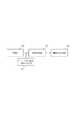
図1は本実施形態の画像処理装置の機能構成を示す図である。(Embodiment 1)
FIG. 1 is a diagram illustrating a functional configuration of the image processing apparatus according to the present embodiment.
本発明の画像処理装置は画像入力部100と顔画像生成パラメータ抽出部101とキャッチライト設定部102から構成される。 The image processing apparatus according to the present invention includes an
顔画像生成パラメータ抽出部101で抽出される顔画像生成パラメータとは、例えば、入力画像中に含まれる顔画像を記述するために必要な角度(顔の向きなど)情報パラメータ、位置情報パラメータ(目領域中の瞳孔の位置、虹彩の位置など)、色情報パラメータ(顔の各パーツの色成分値など)などを示すが、これら角度情報パラメータ、位置情報パラメータ、色情報パラメータに限定されるわけではない。 The face image generation parameters extracted by the face image generation
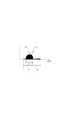
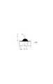
画像入力部100は、デジタルカメラのCCDセンサなどからの信号をAD変換して得られるデジタル画像を入力画像とする。図2は、顔画像生成パラメータ抽出部の詳細構成を示した図である。同図に示すように、顔画像生成パラメータ抽出部101は、目・口・顔位置検出部110と顔の向き・大きさ検出部111と瞳孔・虹彩領域の位置・大きさ検出部112とから構成されている。図3は、人間の目領域の構成を示した図である。目領域は、瞳孔113と虹彩114と白目115とを含んでいる。 The
目・口・顔位置検出部110は、画像入力部100で得られた画像に対して目・口・顔の位置を検出する。例えば、Convolutional Neural Network(Yann LeCun and Yoshua Bengio“Convolutinal Networks for Images,Speech,and Time Series”The Handbook of Brain Theory and Neural Networks,pp255−258 1995など参照)を用いることにより顔・目・口候補位置検出を行い、これら顔・目・口候補位置検出の空間的な配置関係から顔・目・口検出位置を決定する方法などがある。図4は、Convolutinal Neural Networkを用いて検出した顔検出位置121・目検出位置120・口検出位置122を示した図である。 The eye / mouth / face
図5は、顔が正面を向いている場合の左右目と口検出位置間の距離を示した図であり、図6は、顔が左回転した場合の左右目と口検出位置間の距離を示した図である。顔の向き検出部111における顔の向きは、目・口・顔位置検出部110で得られた目(120)・口(122)・顔(121)検出位置から、右目検出位置と顔検出位置間の距離(130)と、左目検出位置と顔検出位置間の距離(131)との比により算出する。 FIG. 5 is a diagram showing the distance between the left and right eyes and the mouth detection position when the face is facing the front, and FIG. 6 shows the distance between the left and right eyes and the mouth detection position when the face is rotated to the left. FIG. The face orientation in the face orientation detection unit 111 is determined from the eye (120), mouth (122), and face (121) detection positions obtained by the eye / mouth / face
つまり、図5のように正面を向いている場合には、右目検出位置と顔検出位置間の距離(130)と、左目検出位置と顔検出位置間の距離(131)との比が1対1であり、図6のように顔が右に回転した場合には、右目検出位置と顔検出位置間の距離(133)は、正面を向いている場合の右目検出位置と顔検出位置間の距離(130)より短くなり、左目検出位置と顔検出位置間の距離(134)は、正面を向いている場合の左目検出位置と顔検出位置間の距離(131)より長くなる。よって、この目検出位置と顔検出位置間の距離を用いることによって顔の向きを推定している。 That is, when facing the front as shown in FIG. 5, the ratio between the distance (130) between the right eye detection position and the face detection position and the distance (131) between the left eye detection position and the face detection position is one pair. When the face is rotated to the right as shown in FIG. 6, the distance (133) between the right eye detection position and the face detection position is between the right eye detection position and the face detection position when facing the front. The distance (130) is shorter than the distance (130), and the distance (134) between the left eye detection position and the face detection position is longer than the distance (131) between the left eye detection position and the face detection position when facing the front. Therefore, the face orientation is estimated by using the distance between the eye detection position and the face detection position.
正面を向いている場合を0度として、顔が左方向に軸回転した場合の回転角αは The angle of rotation α when the face is turned to 0 degrees and the face is pivoted to the left is

などのように表される。また、顔の上方向に軸回転した場合の回転角βは
などのように表される。
瞳孔・虹彩領域の位置・大きさ判定部112は目領域中の瞳孔領域を含んだ虹彩領域の位置と大きさを算出するモジュールであり、本実施形態においては瞳孔領域を含んだ虹彩領域を瞳孔・虹彩領域と書く。瞳孔・虹彩領域の位置と大きさを算出する方法は、例えば、画像入力部100で得られた画像に対して図7のように2値化閾値処理(例えば、閾値50とするが、この値に限定されるわけではない。)を行うことによって2値化処理画像140を算出し、口・目・顔位置検出部110で得られた目と顔の検出位置を用いて図7に示すように左右それぞれの目領域のみを囲う矩形の右目領域141と左目領域142を決定する。 The position /
そして、それぞれの目領域において図8,9に示すように縦・横方向のヒストグラムを作成し、作成した図8の横方向のヒストグラムより目の横(x)方向の長さ150、瞳孔・虹彩領域151、ヒストグラムの最大値を示すx座標より瞳孔・虹彩領域の横方向中心位置152を得る。また、図9の縦方向のヒストグラムの中心より瞳孔・虹彩領域中心位置153、目の縦(y)方向の長さ154を得る。 8 and 9, vertical and horizontal histograms are created in the respective eye regions. The horizontal (x)
図10、11は瞳孔・虹彩領域が目領域の中心にある場合、すなわち正面を向いている場合の目領域における横・縦方向のヒストグラムをそれぞれ示しており、瞳孔・虹彩領域の縦・横方向中心位置162、164が抽出された目の横(x)方向の長さ160,目の縦(y)方向の長さ165の中点とほぼ同じ位置にある。 FIGS. 10 and 11 show horizontal and vertical histograms in the eye region when the pupil / iris region is at the center of the eye region, that is, when facing the front, respectively. The
図12、13は瞳孔・虹彩領域が目領域の中心から横(x)方向に移動した場合の横・縦方向のヒストグラムを示しており、瞳孔・虹彩領域の横方向中心位置173が抽出された目の横(x)方向の長さの中心位置174と異なっている。 FIGS. 12 and 13 show horizontal and vertical histograms when the pupil / iris area moves in the horizontal (x) direction from the center of the eye area, and the
図14、15は瞳孔・虹彩領域が目領域の中心から縦(y)方向に移動した場合の横・縦方向のヒストグラムを示しており、瞳孔・虹彩領域の縦方向中心位置185が抽出された目の縦(y)方向の長さの中心位置186と異なっている。ヒストグラムにおいて複数の山が発生した場合には最も大きい山を示すヒストグラムを用いることによって、瞳孔・虹彩領域の中心位置185、瞳孔・虹彩領域187を得る。 FIGS. 14 and 15 show horizontal and vertical histograms when the pupil / iris region moves in the vertical (y) direction from the center of the eye region, and the
よって、これら図8〜15のヒストグラムに見られるように、目領域中の2値化画像のヒストグラムを用いることによって、目領域中の瞳孔・虹彩領域の中心位置を抽出することができる。なお、図10、11に示すヒストグラムはそれぞれ図8、9と同じである。 Therefore, as can be seen in the histograms of FIGS. 8 to 15, the center position of the pupil / iris region in the eye region can be extracted by using the histogram of the binarized image in the eye region. The histograms shown in FIGS. 10 and 11 are the same as those in FIGS.
図16は、キャッチライト設定部の詳細構成を示した図である。キャッチライト設定部102は、図16のようにキャッチライトの大きさ設定部190とキャッチライトの位置設定部191から構成される。 FIG. 16 is a diagram illustrating a detailed configuration of the catchlight setting unit. The
キャッチライトの大きさ設定部190は、瞳孔・虹彩領域の位置大きさ検出部112で得られた瞳孔・虹彩領域の大きさからキャッチライトの大きさを決定する。この実施形態においてはキャッチライトに用いる形状は円形としているが、キャッチライトの形状は円形に限定されるわけではない。 The catchlight
図17は、キャッチライトの大きさを決定する場合の目領域における横方向ヒストグラムとキャッチライトの大きさとの関係を示した図である。ここでは円形キャッチライトの直径は、瞳孔・虹彩領域の大きさ200の1/5の長さとしている。この円形キャッチライトの直径も、瞳の長さの1/5に限定されるわけではなく、さらに、キャッチライトの直径を決定する際の基準となる特徴は、瞳の大きさ以外に例えば、顔のサイズなどを用いてもよい。 FIG. 17 is a diagram showing a relationship between the horizontal histogram in the eye region and the size of the catchlight when the size of the catchlight is determined. Here, the diameter of the circular catchlight is 1/5 of the
キャッチライトの位置設定部191は、瞳孔・虹彩領域中のキャッチライトの位置を設定する。本実施形態では、瞳孔・虹彩領域の中心を基準としてキャッチライトの位置を設定しているが、必ずしも瞳孔・虹彩領域の中心を基準としてキャッチライトの設定を行う必要はない。 The catchlight
図18は、顔の向きを水平面内(Z軸周りの回転)左方向に回転させて視線方向が正面を向いた場合を示した図である。瞳孔・虹彩領域の中心を基準とした瞳孔・虹彩領域中のキャッチライトの位置は、図18のように顔の向き212、目領域中心211と瞳孔・虹彩領域中心210間距離(視線方向)などによって決まる。 FIG. 18 is a diagram illustrating a case where the direction of the face is rotated to the left in the horizontal plane (rotation around the Z axis) and the line-of-sight direction is directed to the front. The position of the catch light in the pupil / iris area with reference to the center of the pupil / iris area is the
正面を向いている状態で、瞳孔・虹彩領域の中心にキャッチライトがある場合を基準とし、顔の回転によりキャッチライトが目領域を移動する横軸(x)方向の位置ベクトルL1x、縦軸(y)方向の位置ベクトルL1yとすると
g*L1x=−sin(α)
左方向ベクトル:+右方向ベクトル:−
g*L1y=−sin(β)
上方向ベクトル:+下方向ベクトル:−
α:水平面内方向(図18のZ軸周りの回転)の回転角
β:垂直面内方向の回転角(図18のZ軸を含む面)
g:顔サイズによって決定される定数値
となる。The position vector L1x in the horizontal axis (x) direction where the catch light moves in the eye area by the rotation of the face with the catch light at the center of the pupil / iris area in the state of facing the front, the vertical axisAssuming that the position vector L1y in the (y) direction, g * L1x = −sin (α)
Left direction vector: + Right direction vector:-
g * L1y = −sin (β)
Up vector: + Down vector:-
α: rotation angle in the horizontal plane direction (rotation around the Z axis in FIG. 18) β: rotation angle in the vertical plane direction (plane including the Z axis in FIG. 18)
g: A constant value determined by the face size.
図19は、顔が正面を向いている場合のキャッチライトの位置を基準として、顔の向きを水平面内左方向に回転させた場合のキャッチライト位置ベクトルを示した図である。顔を正面向きから左軸方向に回転させた場合の横軸(x)方向の位置ベクトルをL1xで表している。FIG. 19 is a diagram showing a catch light position vector when the face direction is rotated leftward in the horizontal plane with reference to the position of the catch light when the face is facing the front. A position vector in the horizontal axis (x) direction when the face is rotated from the front direction to the left axis direction is represented by L1x .
また、目領域の中心を基準とし、目領域の中心と瞳孔・虹彩領域の中心の横軸(x)方向の位置ベクトルをL2x(目領域の中心から左方向:+目領域の中心から右方向:−)、縦軸(y)方向の位置ベクトルをL2y(目領域の中心から下方向:−目領域の中心から上方向:+)とする。よって、これらの式より瞳孔・虹彩領域の中心からのキャッチライト移動距離Lx、LyはLx=(g*L1x−h*L2x)、Ly=(g*L1y−h*L2y)により算出される。g,hは顔のサイズによって決定される定数値である。The position vector in the horizontal axis (x) direction between the center of the eye region and the center of the pupil / iris region is L2x (leftward from the center of the eye region: + right from the center of the eye region). The position vector in the direction: −) and the vertical axis (y) is L2y (downward from the center of the eye region:−upward from the center of the eye region: +). Therefore, from these equations, the catch light movement distances Lx and Ly from the center of the pupil / iris region are Lx = (g * L1x −h * L2x ) and Ly = (g * L1y −h *). L2y ). g and h are constant values determined by the size of the face.
これにより、図18のように顔は水平面内の左方向(図18のZ軸周りの回転)を向いているが視線方向は正面方向を向いている場合、顔の向きからはL1x(ベクトルの大きさ:−)が算出され、視線方向からはL2x(ベクトルの大きさ:−)が算出される。よって、Accordingly, as shown in FIG. 18, when the face is facing leftward in the horizontal plane (rotation around the Z axis in FIG. 18) but the line-of-sight direction is facing the front direction, L1x (vector) Is calculated from the line-of-sight direction, and L2x (vector size: −) is calculated. Therefore,
図20は、実施形態1における全体処理手順を示したフローチャートであり、顔画像生成パラメータ抽出からキャッチライト位置を設定するまでの手順を示している。 FIG. 20 is a flowchart showing the overall processing procedure in the first embodiment, showing the procedure from face image generation parameter extraction to catchlight position setting.
ステップS230において顔画像生成パラメータを抽出し、顔画像生成パラメメータを用いて顔の向きを抽出する(ステップS231)。一方、ステップS232において顔画像生成パラメータを用いて目領域を決定し、ステップS233で目領域における縦・横方向ヒストグラムを生成し、この縦・横方向ヒストグラムを用いてステップS234で瞳孔・虹彩領域の位置・大きさを抽出する。さらに、ステップS235でキャッチライトの大きさを決定し、ステップS236で視線方向を抽出する。ステップS237では、ステップS231で抽出された顔の向きとステップS236で抽出された視線方向とステップS235で抽出されたキャッチライトの大きさとを用いることによって、キャッチライトの位置と大きさとが設定される。 In step S230, face image generation parameters are extracted, and the face orientation is extracted using the face image generation parameters (step S231). On the other hand, the eye region is determined using the face image generation parameter in step S232, and the vertical and horizontal histograms in the eye region are generated in step S233, and the pupil / iris region is determined in step S234 using the vertical and horizontal histograms. Extract position and size. Further, the size of the catch light is determined in step S235, and the line-of-sight direction is extracted in step S236. In step S237, the position and size of the catchlight are set by using the face orientation extracted in step S231, the line-of-sight direction extracted in step S236, and the size of the catchlight extracted in step S235. .
(実施形態2)
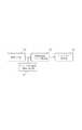
図21は、実施形態2の画像処理装置の機能構成を示す図であり、画像入力部300と顔画像生成パラメータ抽出部301と色欠陥検出・補正部302とキャッチライト付加・補正判定部303とキャッチライト設定部304から構成される。(Embodiment 2)
FIG. 21 is a diagram illustrating a functional configuration of the image processing apparatus according to the second embodiment. The
実施形態2の画像入力部300と顔画像生成パラメータ抽出部301は実施形態1同様の動作を行う。 The
色欠陥検出・補正部302は、画像中の色欠陥検出・補正処理を行う。例えば、ストロボ発光時に起こる赤目の検出・補正などが主な例である。本実施形態2では色欠陥・補正処理を赤目領域検出・補正としているが、必ずしも赤目領域検出・補正に限られるわけではない。赤目検出は、例えば、顔画像生成パラメータ抽出部301で抽出された目の位置検出パラメータを用いて目領域を決定し、目領域に対して顔画像生成パラメータ抽出部301で抽出された色情報パラメータを用いて赤目検出を行う。 The color defect detection /
もし、所定値以上の赤色成分の領域が検出された場合には、赤目が発生していると判定を行う。赤目補正処理に関しては、例えば、あらかじめ用意しておいた虹彩領域の色を用いて赤目領域を補正する方法などがある。 If a red component area of a predetermined value or more is detected, it is determined that red eyes are generated. As for the red-eye correction process, for example, there is a method of correcting the red-eye area using the color of the iris area prepared in advance.
キャッチライト付加・補正部303は、画像入力部300で得られた画像を分析することにより得られる顔画像生成パラメータを用いて、色補正後の画像のキャッチライト有無判定を行う。キャッチライトの有無判定は、例えば、所定値以上の輝度値(例えば、輝度値200など)が目領域にあるかという判定方法がある。 The catchlight addition /
キャッチライト設定部304は、色欠陥の補正処理を行った後、実施形態1で説明したような方法を用いてキャッチライト設定を行う。なお、実施形態1でも述べた通り、キャッチライトの設定は、実施形態1で説明した方法に限られるわけではない。 The catch
図22は、色欠陥検出・補正処理後にキャッチライト設定処理を行う場合の処理手順を示すフローチャートであり、色欠陥検出・補正処理ステップS310を行った後にステップS311においてキャッチライトがないと判定された場合には、ステップS312においてキャッチライトが設定される。ステップS311において、キャッチライトがあると判定された場合には何もしない。 FIG. 22 is a flowchart showing a processing procedure when catchlight setting processing is performed after color defect detection / correction processing. After performing color defect detection / correction processing step S310, it is determined that there is no catchlight in step S311. In that case, a catch light is set in step S312. If it is determined in step S311 that there is a catchlight, nothing is done.
(実施形態3)
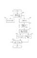
図23は、実施形態3における撮像装置の機能構成を示した図であり、撮像部400と画像処理部401と画像2次記憶部402から構成されている。図24は、撮像部400の詳細構成を示した図である。図24に示すように、撮像部400は、結像光学系410と固体撮像素子411と映像信号処理412と画像1次記憶部413などから構成される。(Embodiment 3)
FIG. 23 is a diagram illustrating a functional configuration of the imaging apparatus according to the third embodiment, and includes an
図25は、画像処理部401の詳細構成を示した図である。図25に示すように、画像処理部401は、画像1次記憶部402からデジタル画像の読み出しを行う画像入力部420と、顔画像生成パラメータ抽出部421と、色欠陥検出・補正部422と、キャッチライト付加・補正判定部423と、キャッチライト設定部424で構成される。以下、詳細を説明する。 FIG. 25 is a diagram illustrating a detailed configuration of the
撮像部400の結像光学系410は、例えばレンズなどであり、固体撮像素子411は例えばCCDなどであり、撮影画像を電気信号に変換する。固体撮像素子411で得られた電気的な信号は、映像信号処理回路412においてAD変換される。また、映像信号処理回路412において得られたデジタル画像は、画像1次記憶部413において記憶媒体に記憶される。記憶媒体としては、例えばフラッシュメモリなどがあるが、フラッシュメモリに限定されるわけではない。 The imaging
画像処理部401における画像入力部420は、画像1次記憶部413からデジタル画像の読み出しを行う。 An
顔画像生成パラメータ抽出部421は、画像入力部420で得られたデジタル画像に対して実施形態1、2と同様の処理を行うことによって、画像データの分析を行う。 The face image generation
色欠陥検出・補正部422は、実施形態2と同様に、顔画像生成パラメータを用いて、目領域に所定値以上の赤色成分領域が含まれている場合には赤目と判定し、補正する。この補正方法は、実施形態2の他に、例えば、次のような方法がある。 Similar to the second embodiment, the color defect detection /
図26は、色欠陥がある場合の所定値以上の明度領域432と瞳孔・虹彩領域431とを含む目領域430を示す図である。図26のように、瞳孔・虹彩領域431において、所定値(例えば明度値200など)以上の明度領域432を持つ画素を検出し、この所定値以上の明度領域を持つ領域を除いた領域を補正する方法がある。 FIG. 26 is a diagram illustrating an
図27は、瞳孔・虹彩領域440における所望のキャッチライトの大きさ441と検出された所定値以上の明度領域442を示した図である。 FIG. 27 is a diagram showing a desired
キャッチライト付加・補正判定部423は、色欠陥検出・補正部422による色補正後の領域において、図27の瞳孔・虹彩領域440中で、所定値以上の明度値(例えば明度値200など)を持つ領域442が、顔画像生成パラメータを用いることによって決定される所望のキャッチライトの大きさ441(例えば明度値200を示す領域の直径が瞳孔・虹彩領域の1/5など)以下の場合に、キャッチライト範囲を拡大する必要があると判定する。なお、所望のキャッチライトの大きさは、画像生成パラメータの一つである瞳孔・虹彩領域から決定しても良いし、他のパラメータを用いても良い。 The catchlight addition /
さらに必要ならば、キャッチライトが抽出された領域における色情報が、所望の色(例えば、白色成分など)と異なる場合には、キャッチライト領域における色を補正する必要があると判定する。 Further, if necessary, if the color information in the area where the catchlight is extracted is different from a desired color (for example, white component), it is determined that the color in the catchlight area needs to be corrected.
キャッチライト設定部424は、キャッチライト付加・補正判定部423で得られた所定値以上の明度(例えば明度値200など)領域442の中心位置、色情報、顔画像生成パラメータの一つである瞳孔・虹彩領域の大きさで決定されるキャッチライトの大きさ(例えば、瞳孔・虹彩領域の大きさの1/5の直径を持つ円など)を用いて、キャッチライトの付加または補正が設定する。 The
なお、キャッチライトの大きさは、瞳孔領域、虹彩領域もしくは両方を含む領域、画像生成パラメータから得られる顔のサイズ、もしくは目のサイズを用いてもよく、形状は円形の他の形状を用いても良い。補正時に用いるキャッチライトの色は、キャッチライト付加・補正判定部423で得られた所定値以上の明度領域の色情報を用いてもよいし、あらかじめ用意しておいた色情報(白色など)を用いても良い。また、キャッチライト範囲を拡大するだけでなく、検出されたキャッチライトのサイズが基準値より大きい場合(金目など)は縮小する。 Note that the size of the catch light may be a pupil area, an iris area, or an area including both, a face size obtained from image generation parameters, or an eye size. Also good. The color of the catchlight used at the time of correction may be the color information of the brightness area that is greater than or equal to the predetermined value obtained by the catchlight addition /
なお、キャッチライト設定における補正処理では、キャッチライトの大きさ、色の補正をすべて行う必要はない。 In the correction process in catchlight setting, it is not necessary to correct all the size and color of the catchlight.
図28は、実施形態3の画像処理部401におけるキャッチライト領域検出からキャッチライト設定までの処理手順を示すフローチャートである。 FIG. 28 is a flowchart illustrating a processing procedure from catchlight region detection to catchlight setting in the
ステップS450でキャッチライト領域を抽出し、ステップS451で所定明度領域が所定値以下である場合にはキャッチライト設定する必要があると判定され、ステップS452でキャッチライト大きさの設定がされ、ステップS453でキャッチライト位置が設定される。ステップS451で所定明度領域が所定値以下でないと判定された場合にはキャッチライト設定必要なしと判定され、何も処理を行わない。 In step S450, a catch light area is extracted. In step S451, if the predetermined brightness area is equal to or smaller than a predetermined value, it is determined that the catch light needs to be set. In step S452, the catch light size is set. To set the catch light position. If it is determined in step S451 that the predetermined brightness area is not less than the predetermined value, it is determined that the catch light setting is not necessary, and no processing is performed.
画像2次記憶部402は、画像処理部401で補正処理されたデジタル画像を記憶媒体などに記憶する。記憶媒体は、例えばフラッシュメモリなどがある。なお、画像1次記憶部413と画像2次記憶部402は同一の記憶媒体を用いても良いし、別の記憶媒体を用いても良い。 The image
(実施形態4)
図29は、実施形態4における撮像装置の機能構成を示した図であり、ストロボ発光部を含む撮像部500と、キャッチライト発生可能性通知部501と、画像処理部502と、画像2次記憶部503とから構成される。(Embodiment 4)
FIG. 29 is a diagram illustrating a functional configuration of the imaging apparatus according to the fourth embodiment. The
撮像部500と画像処理部502と画像2次記憶部503は、実施形態3と同様の処理を行う。また、画像処理部502は実施形態3と同様の構成である。なお、実施形態3でも説明したが、記憶媒体は撮像部500に1次記憶媒体があり、1次記憶媒体と2次記憶媒体は例えば、フラッシュメモリなどがあり、さらに1次記憶媒体と2次記憶媒体は同一の記憶媒体を用いても良い。図30は実施形態4の処理手順を示すフローチャートであり、以下詳細を示す。 The
撮像部500でデジタル画像を得た後に、ステップS510で、撮像部500がストロボ発光したことなどを示すイベントを検出したキャッチライト発生可能性通知部501が、キャッチライト発生可能性ありと判定した場合には、実施形態1などで説明した画像分析を行い、その結果得られる顔画像生成パラメータを用いてステップS511で色欠陥検出を行う。ステップS511において色欠陥が検出されたならば、ステップS512において色欠陥補正処理を行う。 After obtaining a digital image by the
ステップS511において色欠陥が検出されなかった場合には、何もしないでステップS513に進む。ステップS513では、キャッチライト付加・補正処理の判定が行われ、キャッチライト付加または補正処理が必要ならば、ステップS514においてキャッチライト付加・補正処理が行われる。ステップS513において、キャッチライト付加または補正処理が必要ないと判定されたならば、ステップS515に進む。ステップS515においては、必要に応じて色欠陥補正処理、キャッチライト付加・補正処理がなされた画像を記録媒体に記憶する。 If no color defect is detected in step S511, the process proceeds to step S513 without doing anything. In step S513, a catchlight addition / correction process is determined. If a catchlight addition / correction process is necessary, a catchlight addition / correction process is performed in step S514. If it is determined in step S513 that catchlight addition or correction processing is not necessary, the process proceeds to step S515. In step S515, the image subjected to the color defect correction process and the catch light addition / correction process as necessary is stored in a recording medium.
このように、上述したキャッチライト設定機能を撮像装置に設けることにより、撮像した顔の画像中の目の領域にキャッチライトを設定可能な撮像装置を実現することができる。 As described above, by providing the above-described catchlight setting function in the imaging apparatus, it is possible to realize an imaging apparatus capable of setting a catchlight in the eye region in the captured face image.
(実施形態5)
図31は実施形態5の画像処理装置における機能構成を示す図であり、画像入力部600と顔画像生成パラメータ抽出部601とキャッチライト付加・補正判定部402とキャッチライト設定部603から構成される。(Embodiment 5)
FIG. 31 is a diagram illustrating a functional configuration of the image processing apparatus according to the fifth embodiment, which includes an
画像入力部600と顔画像生成パラメータ抽出部601は、実施形態1と同様の動作を行う。 The
キャッチライト付加・補正判定部602は、顔画像生成パラメータ抽出部601で得られた顔画像生成パラメータである画像全体の平均明度値を用いて、算出された画像全体の平均明度値が所定値以下(例えば、平均明度値50以下)の場合には、キャッチライトが必要な状況であると判定される。 The catchlight addition /
なお、キャッチライト付加・補正判定部602においては、画像全体の平均明度値を用いても良いし、他の何らかの特徴を用いて判定を行っても良い。また、キャッチライト付加・補正判定部602においてキャッチライトが必要な状況であると判定された画像に対しては、顔画像生成パラメータ601で算出されたパラメータを用いて、瞳孔・虹彩領域にキャッチライトが存在するか否かを実施形態3に説明したような方法で判定する。 Note that the catchlight addition /
キャッチライト設定部603は、キャッチライト付加・補正判定部602でキャッチライトを設定する必要な状況であり、キャッチライトがない、もしくはキャッチライトの大きさ・位置・色が適切でないと判定された場合には、例えば、実施形態1、3などの方法を用いてキャッチライト設定を行う。 The catchlight setting unit 603 is a situation where the catchlight addition /
図32は、これらの処理手順を示したフローチャートである。ステップS610において画像全体の平均明度が所定値(例えば、平均明度値50)以下の場合は、ステップS611においてキャッチライト領域を検出し、ステップS612においてキャッチライト領域が所定値(例えば、瞳孔・虹彩領域の1/5)以下の場合には、キャッチライト設定する必要があると判定され、ステップS613においてキャッチライト設定が行われる。しかし、ステップS612においてキャッチライト領域が所定値以上の場合には、キャッチライト設定必要なしと判定され、キャッチライト設定は行われない。 FIG. 32 is a flowchart showing these processing procedures. If the average brightness of the entire image is equal to or smaller than a predetermined value (eg, average brightness value 50) in step S610, a catchlight area is detected in step S611, and the catchlight area is determined to be a predetermined value (eg, pupil / iris area) in step S612. In the case of 1/5) or less, it is determined that the catch light needs to be set, and the catch light is set in step S613. However, if the catchlight area is greater than or equal to the predetermined value in step S612, it is determined that the catchlight setting is not necessary, and the catchlight setting is not performed.
(実施形態6)
図33は、実施形態6の画像処理装置における機能構成を示した図であり、画像入力部700とキャッチライト発生可能性通知部701と画像生成パラメータ抽出部702とキャッチライト設定部703から構成される。(Embodiment 6)
FIG. 33 is a diagram illustrating a functional configuration of the image processing apparatus according to the sixth embodiment, and includes an
画像入力部700においては、実施形態1〜4と同様、デジタル画像を入力画像とする。キャッチライト発生可能性通知部701は、キャッチライトの発生を通知するが、このモジュールは画像情報からキャッチライト発生を判定するということではなく、例えばストロボ発光が行われたなどの情報や、撮影者のキャッチライト設定モード選択による情報などを獲得し、通知する。また、キャッチライト設定部703は、実施形態3,4などのような動作を行う。 In the
図34は、実施形態6の処理手順を示すフローチャートである。キャッチライト発生可能性通知ステップS710において、キャッチライトが発生した、もしくはキャッチライト設定モードが選択されたと通知が来た場合には、ステップS711で顔画像生成パラメータを抽出し、この顔画像生成パラメータを用いてステップS712でキャッチライト設定を行う。ステップS710においてキャッチライトが発生したと通知が来なかった場合には何もしない。 FIG. 34 is a flowchart illustrating a processing procedure according to the sixth embodiment. In the catch light occurrence possibility notification step S710, if a notification is received that a catch light has occurred or that the catch light setting mode has been selected, a face image generation parameter is extracted in step S711, and the face image generation parameter is set. In step S712, the catch light is set. If there is no notification that a catch light has occurred in step S710, nothing is done.
(実施形態7)
図35は、実施形態7の画像処理装置における機能構成を示した図であり、画像入力部800とキャッチライト発生可能性通知部802と色欠陥検出・補正処理部803とキャッチライト付加・補正判定部804とキャッチライト設定部805から構成されている。(Embodiment 7)
FIG. 35 is a diagram illustrating a functional configuration of the image processing apparatus according to the seventh embodiment. The
キャッチライト発生可能性通知部801は、実施形態6と同様、画像情報からキャッチライト発生を判定するということではなく、例えばストロボ発光が行われたなどの情報や撮影者のキャッチライト設定モード選択による情報などを獲得し、通知する。 As in the sixth embodiment, the catchlight occurrence
図36は、実施形態7の処理手順を示すフローチャートである。 FIG. 36 is a flowchart illustrating a processing procedure according to the seventh embodiment.
ステップS801でキャッチライト発生可能性ありと通知を受けた場合には、顔画像生成パラメータを用いてステップS811で目領域の色欠陥検出を行い、色欠陥があると判定された場合にはステップS812において色欠陥補正処理を行った後、ステップS813のキャッチライト付加・補正必要を行う。 When it is notified in step S801 that there is a possibility of catchlight generation, the face area generation parameter is used to detect a color defect in the eye area in step S811, and when it is determined that there is a color defect, step S812 is performed. After performing the color defect correction process in step S813, it is necessary to add and correct the catch light in step S813.
ステップS811において色欠陥が検出されなかった場合には、ステップS812の色欠陥補正処理は行わずに、ステップS813でキャッチライト付加・補正の必要性の判定を行う。ステップS813においてキャッチライト付加・補正必要と判定された場合には、ステップS814においてキャッチライトの付加・補正が行われる。ステップS810でキャッチライト発生可能性の通知がなく、ステップS813でキャッチライト付加・補正が必要がないと判定された場合には、何も処理を行わない。 If no color defect is detected in step S811, the color defect correction process in step S812 is not performed, and the necessity of catchlight addition / correction is determined in step S813. If it is determined in step S813 that catchlight addition / correction is necessary, catchlight addition / correction is performed in step S814. If there is no notification of the possibility of catchlight generation in step S810 and it is determined in step S813 that catchlight addition / correction is not necessary, no processing is performed.
図37は、本実施形態に係る画像処理装置のハードウェア構成を示すブロック図である。この画像処理装置は、撮像装置の一部として、もしくは撮像装置と接続されて利用され、上述した補正処理を行なう。 FIG. 37 is a block diagram illustrating a hardware configuration of the image processing apparatus according to the present embodiment. This image processing apparatus is used as a part of the imaging apparatus or connected to the imaging apparatus, and performs the above-described correction processing.
CPU41は、ROM42やRAM43に格納されているプログラムやデータを用いて本装置全体の制御を行うと共に、後述する各処理を実行する。 The CPU 41 controls the entire apparatus using programs and data stored in the ROM 42 and the RAM 43 and executes each process described later.
ROM42は、ブートプログラムや本装置の設定データ等を格納する。 The ROM 42 stores a boot program, setting data of the apparatus, and the like.
RAM43は、CPU41が各種の処理を実行する際に必要とするワークエリアを備えると共に、HDD46からロードされたプログラムやデータを一時的に記憶するためのエリアを備える。 The RAM 43 includes a work area required when the CPU 41 executes various processes, and also includes an area for temporarily storing programs and data loaded from the HDD 46.
キーボード44は、ユーザからの各種の指示をCPU100に対して入力することができる操作部である。更に、マウスなどのポインティングデバイスを備えるようにしてもよい。 The keyboard 44 is an operation unit that can input various instructions from the user to the
CRT45はCPU41による処理結果を文字や画像などでもって表示することができる表示装置である。CRT45に代えて液晶表示装置などを設けてもよい。 The CRT 45 is a display device that can display the result of processing by the CPU 41 using characters, images, and the like. Instead of the CRT 45, a liquid crystal display device or the like may be provided.
ハードディスクドライブ装置(HDD)46は、大容量の外部記憶装置であり、OS(オペレーティングシステム)や、図1に示した各部の機能をCPU41に実現させるためのプログラムやデータが保存されており、これらの一部もしくは全部はCPU41による制御でもってRAM43にロードされる。また、HDD46には、補正データやモデルデータなどが保存されており、これらについても必要に応じてCPU41の制御に従ってRAM43にロードされる。外部記憶装置として、更にCDやDVDなどのドライブ装置を設けてもよい。 The hard disk drive (HDD) 46 is a large-capacity external storage device, and stores programs (OS) and programs and data for causing the CPU 41 to realize the functions of the units shown in FIG. A part or all of these are loaded into the RAM 43 under the control of the CPU 41. Further, correction data, model data, and the like are stored in the HDD 46, and these are also loaded into the RAM 43 according to the control of the CPU 41 as necessary. A drive device such as a CD or a DVD may be further provided as an external storage device.
I/F47は、外部装置とのデータ通信のためのインタフェースである。例えば、補正対象を含む画像のデータを、このI/F47に接続しているディジタルカメラから入力したり、コンピュータからダウンロードしたりすることもできる。なお、画像のデータはRAM43に一時的に記憶され、そこでCPU41の処理対象となる。上述の各部はバス48に接続している。 The I / F 47 is an interface for data communication with an external device. For example, image data including a correction target can be input from a digital camera connected to the I / F 47 or downloaded from a computer. Note that the image data is temporarily stored in the RAM 43 and becomes a processing target of the CPU 41 there. Each unit described above is connected to the
以上説明した実施形態によれば、色欠陥補正後の画像に対してキャッチライトの有無を判定し、キャッチライトがない場合には顔画像生成パラメータを用いてキャッチライト設定を自動的に行うことにより、手動操作による画像補正精度のばらつきを軽減させ、より自然な画像を演出することができる。 According to the embodiment described above, the presence or absence of catchlight is determined for the image after color defect correction, and when there is no catchlight, the catchlight setting is automatically performed using the face image generation parameter. Thus, variation in image correction accuracy due to manual operation can be reduced, and a more natural image can be produced.
また、色欠陥補正後の画像に対してキャッチライトの大きさ、位置、色が適切であるかを判定し顔画像生成パラメータを用いてキャッチライトを補正することによって、手動操作による画像補正精度のばらつきを軽減させ、より自然な画像を演出することができる。 In addition, by determining whether the size, position, and color of the catchlight are appropriate for the image after color defect correction and correcting the catchlight using the face image generation parameters, the image correction accuracy by manual operation can be improved. Variations can be reduced and more natural images can be produced.
更に、入力画像に対してキャッチライトが発生する状況を判定した後、キャッチライトの有無を判定し、キャッチライトがない場合には顔画像生成パラメータを用いてキャッチライト設定を行うことにより、手動操作による画像補正精度のばらつきを軽減させ、より自然な画像を演出することができる。 Furthermore, after determining the situation where a catchlight occurs for the input image, it is determined whether or not there is a catchlight. If there is no catchlight, manual operation is performed by setting the catchlight using the face image generation parameter. Variations in image correction accuracy due to can be reduced, and a more natural image can be produced.
また、入力画像に対してキャッチライトが発生する状況を判定した後、キャッチライトの大きさ、位置、色が適切であるかを判定し顔画像生成パラメータを用いてキャッチライトを補正することによって、手動操作による画像補正精度のばらつきを軽減させ、より自然な画像を演出することができる。 Also, after determining the situation where the catchlight occurs for the input image, by determining whether the size, position, and color of the catchlight are appropriate and correcting the catchlight using the face image generation parameters, Variations in image correction accuracy due to manual operation can be reduced, and more natural images can be produced.
(その他の実施形態)
本発明の目的は、前述した実施形態の機能を実現するソフトウェアのプログラムコードを記録した記録媒体(または記憶媒体)を、カメラもしくはコンピュータのCPUやMPUが記録媒体に格納されたプログラムコードを読み出し実行することによっても、達成されることは言うまでもない。この場合、記録媒体から読み出されたプログラムコード自体が前述した実施形態の機能を実現することになり、そのプログラムコードを記録した記録媒体は本発明を構成することになる。(Other embodiments)
An object of the present invention is to read and execute a program code stored in a recording medium by a camera or computer CPU or MPU from a recording medium (or storage medium) that records a program code of software that realizes the functions of the above-described embodiments. Needless to say, this can also be achieved. In this case, the program code itself read from the recording medium realizes the functions of the above-described embodiment, and the recording medium on which the program code is recorded constitutes the present invention.
また、カメラもしくはコンピュータが読み出したプログラムコードを実行することにより、前述した実施形態の機能が実現されるだけでなく、そのプログラムコードの指示に基づき、カメラ上で稼働しているオペレーティングシステム(OS)などが実際の処理の一部または全部を行い、その処理によって前述した実施形態の機能が実現される場合も含まれることは言うまでもない。 Further, by executing the program code read by the camera or computer, not only the functions of the above-described embodiments are realized, but also an operating system (OS) operating on the camera based on an instruction of the program code. Needless to say, the present invention includes a case where part or all of the actual processing is performed and the functions of the above-described embodiments are realized by the processing.
さらに、記録媒体から読み出されたプログラムコードが、カメラもしくはコンピュータに挿入された機能拡張カードや、カメラもしくはコンピュータに接続された機能拡張ユニットに備わるメモリに書込まれた後、そのプログラムコードの指示に基づき、その機能拡張カードや機能拡張ユニットに備わるCPUなどが実際の処理の一部または全部を行い、その処理によって前述した実施形態の機能が実現される場合も含まれることは言うまでもない。 Furthermore, after the program code read from the recording medium is written in the memory of the function expansion card inserted into the camera or computer or the function expansion unit connected to the camera or computer, the program code instructions On the basis of the above, it is needless to say that the CPU of the function expansion card or the function expansion unit performs part or all of the actual processing and the functions of the above-described embodiments are realized by the processing.
本発明を上記記録媒体に適用する場合、その記録媒体には、先に説明したフローチャートに対応するプログラムコードが格納されることになる。 When the present invention is applied to the recording medium, program code corresponding to the flowchart described above is stored in the recording medium.
Claims (11)
Translated fromJapanese入力された前記画像を分析して、顔領域と目領域と瞳孔・虹彩領域との位置及び大きさを含む顔画像生成パラメータを抽出する顔画像生成パラメータ抽出ステップと、
前記瞳孔・虹彩領域中で所定値以上の明度を持つ領域をキャッチライト領域として検出する検出ステップと、
前記キャッチライト領域が検出された場合に、前記顔画像生成パラメータに基づいて当該キャッチライト領域の大きさが適切か否かを判定する判定ステップと、
前記キャッチライト領域が検出されなかった場合に、前記顔画像生成パラメータに基づいて前記画像に新たにキャッチライトの設定を行い、前記キャッチライト領域の大きさが適切でないと判定された場合に、前記顔画像生成パラメータに基づいて当該キャッチライト領域の大きさを補正するキャッチライト設定ステップとを有することを特徴とする画像処理方法。An input step for inputting an image;
A face image generation parameter extracting step of analyzing the input image and extracting face image generation parameters including positions and sizes of the face region, the eye region, and the pupil / iris region;
A detection step of detecting an area having a lightness of a predetermined value or more in the pupil / iris area as a catchlight area;
A determination step of determining whether or not the size of the catchlight area is appropriate based on the face image generation parameter when the catchlight area is detected;
When the catchlight area is not detected, a new catchlight is set for the image based on the face image generation parameter, and when it is determined that the size of the catchlight area is not appropriate, An image processing method comprising: a catch light setting step of correcting the size of the catch light region based on a face image generation parameter.
入力された前記画像を分析して、顔領域と目領域と瞳孔・虹彩領域との位置及び大きさを含む顔画像生成パラメータを抽出する顔画像生成パラメータ抽出手段と、
前記瞳孔・虹彩領域中で所定値以上の明度を持つ領域をキャッチライト領域として検出する検出手段と、
前記キャッチライト領域が検出された場合に、前記顔画像生成パラメータに基づいて当該キャッチライト領域の大きさが適切か否かを判定する判定手段と、
前記キャッチライト領域が検出されなかった場合に、前記顔画像生成パラメータに基づいて前記画像に新たにキャッチライトの設定を行い、前記キャッチライト領域の大きさが適切でないと判定された場合に、前記顔画像生成パラメータに基づいて当該キャッチライト領域の大きさを補正するキャッチライト設定手段とを有することを特徴とする画像処理装置。An input means for inputting an image;
A face image generation parameter extracting means for analyzing the input image and extracting face image generation parameters including positions and sizes of the face region, the eye region, and the pupil / iris region;
Detecting means for detecting, as a catchlight region, a region having a brightness of a predetermined value or more in the pupil / iris region;
A determination unit that determines whether or not the size of the catchlight area is appropriate based on the face image generation parameter when the catchlight area is detected;
When the catchlight area is not detected, a new catchlight is set for the image based on the face image generation parameter, and when it is determined that the size of the catchlight area is not appropriate, An image processing apparatus comprising: catch light setting means for correcting the size of the catch light region based on a face image generation parameter.
Priority Applications (5)
| Application Number | Priority Date | Filing Date | Title |
|---|---|---|---|
| JP2004223579AJP4537143B2 (en) | 2004-07-30 | 2004-07-30 | Image processing apparatus and method, imaging apparatus, and program |
| US11/571,325US7894666B2 (en) | 2004-07-30 | 2005-07-27 | Image processing method and apparatus, image sensing apparatus, and program |
| CN200580025780.4ACN1993707B (en) | 2004-07-30 | 2005-07-27 | Image processing method and apparatus and image sensing apparatus |
| EP05768840AEP1774466A4 (en) | 2004-07-30 | 2005-07-27 | Image processing method and apparatus, image sensing apparatus, and program |
| PCT/JP2005/014143WO2006011635A1 (en) | 2004-07-30 | 2005-07-27 | Image processing method and apparatus, image sensing apparatus, and program |
Applications Claiming Priority (1)
| Application Number | Priority Date | Filing Date | Title |
|---|---|---|---|
| JP2004223579AJP4537143B2 (en) | 2004-07-30 | 2004-07-30 | Image processing apparatus and method, imaging apparatus, and program |
Publications (2)
| Publication Number | Publication Date |
|---|---|
| JP2006040232A JP2006040232A (en) | 2006-02-09 |
| JP4537143B2true JP4537143B2 (en) | 2010-09-01 |
Family
ID=35905110
Family Applications (1)
| Application Number | Title | Priority Date | Filing Date |
|---|---|---|---|
| JP2004223579AExpired - Fee RelatedJP4537143B2 (en) | 2004-07-30 | 2004-07-30 | Image processing apparatus and method, imaging apparatus, and program |
Country Status (2)
| Country | Link |
|---|---|
| JP (1) | JP4537143B2 (en) |
| CN (1) | CN1993707B (en) |
Families Citing this family (18)
| Publication number | Priority date | Publication date | Assignee | Title |
|---|---|---|---|---|
| JP5009204B2 (en) | 2008-03-14 | 2012-08-22 | オリンパスイメージング株式会社 | Image capturing apparatus and image composition method in image capturing apparatus |
| JP4548542B1 (en)* | 2009-06-30 | 2010-09-22 | ソニー株式会社 | Information processing apparatus, information processing method, and program |
| JP5479068B2 (en)* | 2009-12-16 | 2014-04-23 | キヤノン株式会社 | Image processing apparatus and image processing method |
| CN102655565B (en)* | 2011-03-02 | 2015-05-20 | 中山市云创知识产权服务有限公司 | Anti-red-eye portrait shooting system and method |
| JP5719223B2 (en)* | 2011-04-25 | 2015-05-13 | オリンパスイメージング株式会社 | Image recording apparatus, recording method, and program |
| CN103246865B (en)* | 2012-02-03 | 2016-05-04 | 展讯通信(上海)有限公司 | Method and the device of the method for detection blood-shot eye illness and device, removal blood-shot eye illness |
| JP6260094B2 (en)* | 2013-03-21 | 2018-01-17 | カシオ計算機株式会社 | Image processing apparatus, image processing method, and program |
| JP6354118B2 (en)* | 2013-03-21 | 2018-07-11 | カシオ計算機株式会社 | Image processing apparatus, image processing method, and program |
| CN104299188B (en)* | 2013-07-18 | 2018-10-30 | 深圳富泰宏精密工业有限公司 | Image correcting method and system |
| CN104637031B (en)* | 2013-11-12 | 2017-08-29 | 华为终端有限公司 | Eyes image treating method and apparatus |
| CN104778729A (en)* | 2014-01-09 | 2015-07-15 | 上海帝仪科技有限公司 | Iris extraction method and equipment under uneven illumination condition |
| JP6299300B2 (en) | 2014-03-14 | 2018-03-28 | オムロン株式会社 | Image processing apparatus and image processing method |
| JP6327071B2 (en)* | 2014-09-03 | 2018-05-23 | オムロン株式会社 | Image processing apparatus and image processing method |
| WO2016159255A1 (en)* | 2015-03-31 | 2016-10-06 | 国立大学法人静岡大学 | Mouth region detection device and mouth region detection method |
| CN109035136B (en)* | 2018-07-26 | 2023-05-09 | 北京小米移动软件有限公司 | Image processing method and device and storage medium |
| CN113491513B (en) | 2020-04-08 | 2023-06-30 | 华为技术有限公司 | Heart rhythm detection control method and terminal |
| CN113409210B (en)* | 2021-06-17 | 2023-06-02 | 杭州海康威视数字技术股份有限公司 | Pupil bright spot eliminating method |
| WO2023276123A1 (en)* | 2021-07-01 | 2023-01-05 | 日本電気株式会社 | Learning system, inference system, learning method, and computer program |
Family Cites Families (7)
| Publication number | Priority date | Publication date | Assignee | Title |
|---|---|---|---|---|
| JPH1075374A (en)* | 1996-08-30 | 1998-03-17 | Fuji Photo Film Co Ltd | Image processing unit and its method |
| JP4050842B2 (en)* | 1998-06-15 | 2008-02-20 | 富士フイルム株式会社 | Image processing method |
| JP2000134486A (en)* | 1998-10-22 | 2000-05-12 | Canon Inc | Image processing apparatus, image processing method, and storage medium |
| GB2379819B (en)* | 2001-09-14 | 2005-09-07 | Pixology Ltd | Image processing to remove red-eye features |
| US7403646B2 (en)* | 2002-10-24 | 2008-07-22 | Canon Kabushiki Kaisha | Image processing apparatus, image processing method, program, and recording medium for generating a difference image from a first radiographic image and second radiographic image |
| JP2004208132A (en)* | 2002-12-26 | 2004-07-22 | Nikon Corp | Color defective area correction method, color defective area correction processing program, image processing apparatus |
| JP2005222152A (en)* | 2004-02-03 | 2005-08-18 | Omron Corp | Image correcting device |
- 2004
- 2004-07-30JPJP2004223579Apatent/JP4537143B2/ennot_activeExpired - Fee Related
- 2005
- 2005-07-27CNCN200580025780.4Apatent/CN1993707B/ennot_activeExpired - Fee Related
Also Published As
| Publication number | Publication date |
|---|---|
| CN1993707A (en) | 2007-07-04 |
| CN1993707B (en) | 2012-12-19 |
| JP2006040232A (en) | 2006-02-09 |
Similar Documents
| Publication | Publication Date | Title |
|---|---|---|
| JP4537143B2 (en) | Image processing apparatus and method, imaging apparatus, and program | |
| JP4218712B2 (en) | Face detection device, imaging device, and face detection method | |
| US9020210B2 (en) | Image processing system, image processing apparatus, image processing method, and program | |
| JP4218711B2 (en) | Face detection device, imaging device, and face detection method | |
| JP4078334B2 (en) | Image processing apparatus and image processing method | |
| US10176616B2 (en) | Automatic capture and refinement of a digital image of a group of people without user intervention | |
| JPWO2009098894A1 (en) | Electronic camera and image processing method | |
| US10404912B2 (en) | Image capturing apparatus, image processing apparatus, image capturing system, image processing method, and storage medium | |
| JPWO2010073619A1 (en) | Imaging device | |
| JP2014063265A (en) | Image processor, image processing method and program | |
| US8368764B2 (en) | Digital photographing apparatus and method for controlling the same | |
| US11941498B2 (en) | Facial motion detection and image correction method and apparatus | |
| US20160110840A1 (en) | Image processing method, image processing device, and robot system | |
| JP4148903B2 (en) | Image processing apparatus, image processing method, and digital camera | |
| JP2006295646A (en) | Image processor and image processing program | |
| JP5504990B2 (en) | Imaging apparatus, image processing apparatus, and program | |
| JP2007312206A (en) | Imaging apparatus and image reproduction apparatus | |
| JP6098133B2 (en) | Face component extraction device, face component extraction method and program | |
| JP4807170B2 (en) | Pattern detection method, pattern detection program, pattern detection apparatus, and imaging apparatus | |
| JP2013098746A (en) | Imaging apparatus, imaging method, and program | |
| JP4501701B2 (en) | Image capturing apparatus, image processing method for image capturing apparatus, and program | |
| CN117251050A (en) | Control method, control device and display system of control device | |
| WO2022196093A1 (en) | Information processing device, line-of-sight detection method, and program | |
| JP2008158343A (en) | Imaging device and control method thereof | |
| JP2006323779A (en) | Image processing method and image processing apparatus |
Legal Events
| Date | Code | Title | Description |
|---|---|---|---|
| A621 | Written request for application examination | Free format text:JAPANESE INTERMEDIATE CODE: A621 Effective date:20070730 | |
| A131 | Notification of reasons for refusal | Free format text:JAPANESE INTERMEDIATE CODE: A131 Effective date:20091013 | |
| A521 | Request for written amendment filed | Free format text:JAPANESE INTERMEDIATE CODE: A523 Effective date:20091214 | |
| RD04 | Notification of resignation of power of attorney | Free format text:JAPANESE INTERMEDIATE CODE: A7424 Effective date:20100201 | |
| A131 | Notification of reasons for refusal | Free format text:JAPANESE INTERMEDIATE CODE: A131 Effective date:20100323 | |
| A521 | Request for written amendment filed | Free format text:JAPANESE INTERMEDIATE CODE: A523 Effective date:20100524 | |
| TRDD | Decision of grant or rejection written | ||
| A01 | Written decision to grant a patent or to grant a registration (utility model) | Free format text:JAPANESE INTERMEDIATE CODE: A01 Effective date:20100615 | |
| A01 | Written decision to grant a patent or to grant a registration (utility model) | Free format text:JAPANESE INTERMEDIATE CODE: A01 | |
| A61 | First payment of annual fees (during grant procedure) | Free format text:JAPANESE INTERMEDIATE CODE: A61 Effective date:20100617 | |
| FPAY | Renewal fee payment (event date is renewal date of database) | Free format text:PAYMENT UNTIL: 20130625 Year of fee payment:3 | |
| R150 | Certificate of patent or registration of utility model | Free format text:JAPANESE INTERMEDIATE CODE: R150 | |
| LAPS | Cancellation because of no payment of annual fees |