JP4536766B2 - Display device - Google Patents
Display deviceDownload PDFInfo
- Publication number
- JP4536766B2 JP4536766B2JP2007273109AJP2007273109AJP4536766B2JP 4536766 B2JP4536766 B2JP 4536766B2JP 2007273109 AJP2007273109 AJP 2007273109AJP 2007273109 AJP2007273109 AJP 2007273109AJP 4536766 B2JP4536766 B2JP 4536766B2
- Authority
- JP
- Japan
- Prior art keywords
- image
- pointer
- frame
- pointer image
- trajectory
- Prior art date
- Legal status (The legal status is an assumption and is not a legal conclusion. Google has not performed a legal analysis and makes no representation as to the accuracy of the status listed.)
- Expired - Fee Related
Links
Images


Classifications
- B—PERFORMING OPERATIONS; TRANSPORTING
- B60—VEHICLES IN GENERAL
- B60K—ARRANGEMENT OR MOUNTING OF PROPULSION UNITS OR OF TRANSMISSIONS IN VEHICLES; ARRANGEMENT OR MOUNTING OF PLURAL DIVERSE PRIME-MOVERS IN VEHICLES; AUXILIARY DRIVES FOR VEHICLES; INSTRUMENTATION OR DASHBOARDS FOR VEHICLES; ARRANGEMENTS IN CONNECTION WITH COOLING, AIR INTAKE, GAS EXHAUST OR FUEL SUPPLY OF PROPULSION UNITS IN VEHICLES
- B60K35/00—Instruments specially adapted for vehicles; Arrangement of instruments in or on vehicles
- B60K35/60—Instruments characterised by their location or relative disposition in or on vehicles
- B—PERFORMING OPERATIONS; TRANSPORTING
- B60—VEHICLES IN GENERAL
- B60K—ARRANGEMENT OR MOUNTING OF PROPULSION UNITS OR OF TRANSMISSIONS IN VEHICLES; ARRANGEMENT OR MOUNTING OF PLURAL DIVERSE PRIME-MOVERS IN VEHICLES; AUXILIARY DRIVES FOR VEHICLES; INSTRUMENTATION OR DASHBOARDS FOR VEHICLES; ARRANGEMENTS IN CONNECTION WITH COOLING, AIR INTAKE, GAS EXHAUST OR FUEL SUPPLY OF PROPULSION UNITS IN VEHICLES
- B60K35/00—Instruments specially adapted for vehicles; Arrangement of instruments in or on vehicles
- B60K35/20—Output arrangements, i.e. from vehicle to user, associated with vehicle functions or specially adapted therefor
- B60K35/21—Output arrangements, i.e. from vehicle to user, associated with vehicle functions or specially adapted therefor using visual output, e.g. blinking lights or matrix displays
- B60K35/213—Virtual instruments
- B—PERFORMING OPERATIONS; TRANSPORTING
- B60—VEHICLES IN GENERAL
- B60K—ARRANGEMENT OR MOUNTING OF PROPULSION UNITS OR OF TRANSMISSIONS IN VEHICLES; ARRANGEMENT OR MOUNTING OF PLURAL DIVERSE PRIME-MOVERS IN VEHICLES; AUXILIARY DRIVES FOR VEHICLES; INSTRUMENTATION OR DASHBOARDS FOR VEHICLES; ARRANGEMENTS IN CONNECTION WITH COOLING, AIR INTAKE, GAS EXHAUST OR FUEL SUPPLY OF PROPULSION UNITS IN VEHICLES
- B60K35/00—Instruments specially adapted for vehicles; Arrangement of instruments in or on vehicles
- B60K35/20—Output arrangements, i.e. from vehicle to user, associated with vehicle functions or specially adapted therefor
- B60K35/21—Output arrangements, i.e. from vehicle to user, associated with vehicle functions or specially adapted therefor using visual output, e.g. blinking lights or matrix displays
- B60K35/22—Display screens
- B—PERFORMING OPERATIONS; TRANSPORTING
- B60—VEHICLES IN GENERAL
- B60K—ARRANGEMENT OR MOUNTING OF PROPULSION UNITS OR OF TRANSMISSIONS IN VEHICLES; ARRANGEMENT OR MOUNTING OF PLURAL DIVERSE PRIME-MOVERS IN VEHICLES; AUXILIARY DRIVES FOR VEHICLES; INSTRUMENTATION OR DASHBOARDS FOR VEHICLES; ARRANGEMENTS IN CONNECTION WITH COOLING, AIR INTAKE, GAS EXHAUST OR FUEL SUPPLY OF PROPULSION UNITS IN VEHICLES
- B60K35/00—Instruments specially adapted for vehicles; Arrangement of instruments in or on vehicles
- B60K35/80—Arrangements for controlling instruments
- B60K35/81—Arrangements for controlling instruments for controlling displays
- B—PERFORMING OPERATIONS; TRANSPORTING
- B60—VEHICLES IN GENERAL
- B60K—ARRANGEMENT OR MOUNTING OF PROPULSION UNITS OR OF TRANSMISSIONS IN VEHICLES; ARRANGEMENT OR MOUNTING OF PLURAL DIVERSE PRIME-MOVERS IN VEHICLES; AUXILIARY DRIVES FOR VEHICLES; INSTRUMENTATION OR DASHBOARDS FOR VEHICLES; ARRANGEMENTS IN CONNECTION WITH COOLING, AIR INTAKE, GAS EXHAUST OR FUEL SUPPLY OF PROPULSION UNITS IN VEHICLES
- B60K2360/00—Indexing scheme associated with groups B60K35/00 or B60K37/00 relating to details of instruments or dashboards
- B60K2360/20—Optical features of instruments
- B60K2360/33—Illumination features
Landscapes
- Engineering & Computer Science (AREA)
- Chemical & Material Sciences (AREA)
- Combustion & Propulsion (AREA)
- Transportation (AREA)
- Mechanical Engineering (AREA)
- Instrument Panels (AREA)
- Display Devices Of Pinball Game Machines (AREA)
- Liquid Crystal (AREA)
- Devices For Indicating Variable Information By Combining Individual Elements (AREA)
- Indicating Measured Values (AREA)
- Controls And Circuits For Display Device (AREA)
Description
Translated fromJapanese本発明は、指針を表す指針画像を表示する表示装置に関するものである。 The present invention relates to a display device that displays a pointer image representing a pointer.
指針画像を表示する表示装置として、マトリックス状に複数の画素が形成されている液晶パネル等の表示パネルを備え、指針を表す指針画像と、指針画像の回動軌跡を表す軌跡画像とを、表示パネルに表示する表示装置が開示されている(特許文献1を参照)。 As a display device that displays a pointer image, a display panel such as a liquid crystal panel in which a plurality of pixels are formed in a matrix is provided, and a pointer image that represents a pointer and a trajectory image that represents a rotation trajectory of the pointer image are displayed. A display device that displays on a panel is disclosed (see Patent Document 1).
これは、指針画像の回動範囲を、指針画像の回動方向に沿って複数の扇形部に区画し、複数の扇形部のうち一部の扇形部を、軌跡画像として表示するものである。具体的には、複数の扇形部のうち一部の扇形部を、軌跡画像として指針画像の背景色と異なる色で表示し、複数の扇形部のうち残部の扇形部を、指針画像の背景色で表示する。また、表示パネルでは、1秒間に30フレームの画像が切り替えられ、これにより、指針画像と軌跡画像の各動きが表示される。
特許文献1には記載されていないが、指針画像の回動速度が速い場合、例えば、所定のフレームと次のフレームの間で指針画像の回動角度が大きい場合、指針画像の回動動作がステップ状に飛んでいるように視認され、即ち、指針画像の回動動作が円滑でないため、視認者に違和感を与えるという問題が生じる。 Although not described in
本発明は、このような事情を考慮してなされたものであり、指針画像の動きを円滑に視認させることが可能な表示装置を提供することを目的とする。 The present invention has been made in consideration of such circumstances, and an object of the present invention is to provide a display device that can smoothly recognize the movement of a pointer image.
本発明は上記目的を達成するため、以下の技術的手段を採用する。 In order to achieve the above object, the present invention employs the following technical means.
請求項1に記載の表示装置は、指針を表す指針画像と、指針画像の動きの軌跡を表す軌跡画像とを表示可能な表示パネルと、複数のフレームの指針画像と軌跡画像とを、連続的に切り替えて表示可能なように表示パネルの表示状態を制御する制御手段とを備え、複数のフレームにおいて所定の第1フレームの軌跡画像は、第1フレームの指針画像が表示されている第1部位と、第1フレームに対して1フレーム分前の第2フレームの指針画像が表示された第2部位とを結んで連続して形成されており、指針画像の動きが、指針画像の回動であり、第1フレームの軌跡画像が、第1フレームの指針画像と第2フレームの指針画像とからなる扇形状を有し、且つ、軌跡画像において外周側の円周に、グラデーション部を備え、グラデーション部が、円周側へ向かって指針画像の色調から指針画像の背景の色調へ徐々に変化するグラデーションとして形成されていることを特徴とする。The display device according to
ここで、回動する指針画像の先端側がより長い距離を動くため、先端側の残像は、より不明瞭に、即ち、背景側の色調になる。このため、円周側を、即ち、先端側を背景側の色調で表示するグラデーション部は、指針画像の残像を認識させることができる。このため、円周側を背景側の色調で表示するグラデーション部は、軌跡画像において、指針画像の動きを、より認識させることが可能になる。 Here, since the leading end side of the rotating pointer image moves a longer distance, the afterimage on the leading end side becomes more unclear, that is, the color tone on the background side. For this reason, the gradation part which displays the circumference side, ie, the front end side, with the color tone of the background side can recognize the afterimage of the pointer image. For this reason, the gradation part which displays the circumference side with the color tone of the background side can recognize the movement of the pointer image more in the trajectory image.
以下、本発明による表示装置を図面に基づいて説明する。 Hereinafter, a display device according to the present invention will be described with reference to the drawings.
図1に示す表示装置1は、例えば、車載用の表示装置として使用され、表示パネルである液晶パネル2と、制御手段であるCPU(セントラル・プロセッシング・ユニット)3と描画IC(集積回路)4と、ROM(リード・オンリー・メモリ)31と、RAM(ランダム・アクセス・メモリ)34と、画像メモリ41とを備える。 A
マトリックス状に複数の画素が形成されている液晶パネル2は、図示しない薄膜トランジスタ(TFT)によって駆動されるタイプのアクティブマトリックス方式の液晶パネルである。また、各画素は、赤色画素と緑色画素と青色画素を内蔵し、TFTのゲートに電圧を印加することによって各画素において赤色画素と緑色画素と青色画素に印加する電圧を制御し、これにより、各画素において赤色画素と緑色画素と青色画素の各光透過率を制御する。図示しない白色光を発する発光ダイオードが、液晶パネル2の背後に配置されて液晶パネル2を透過照明する。赤色画素と緑色画素と青色画素の各光透過率が制御されている各画素を発光ダイオードが透過照明することによって、液晶パネル2にフルカラー表示をさせる。 The
CPU3は、当該自動車の速度を検出する速度センサ6から、速度信号を取り込み、描画IC4に入力させる。CPU3は、当該自動車のイグニッションスイッチ7を介してバッテリ8から給電されて動作する。 The CPU 3 takes in the speed signal from the
ROM31は、ポリゴンデータ記憶部32と画像データ記憶部33とを備え、図2に示す速度メータ画像5のポリゴンデータがポリゴンデータ記憶部32に記憶され、速度メータ画像5の画像データが画像データ記憶部33に記憶されている。ポリゴンデータは、速度メータ画像5の表示空間を分割した複数のポリゴン(一般には、3角形の平面)からなり、画像データは、各ポリゴンに貼り付けられるテクスチャからなる。即ち、画像データの各テクスチャを、ポリゴンデータの各ポリゴンに貼り付けることによって、速度メータ画像5が液晶パネル2に描画される。 The
CPU3からの指示により、ポリゴンデータがポリゴンデータ記憶部32からRAM34に転送され、画像データが画像データ記憶部33から画像メモリ41へ転送され、描画IC4は、RAM34のポリゴンデータと、画像メモリ41の画像データと、入力した速度信号とに基いて、各画素において赤色画素と緑色画素と青色画素に印加する電圧を制御し、複数の画素の各表示状態を制御する。この表示状態は、複数のフレームの画像を連続的に切り替えて制御され、具体的には、1秒間に30フレームの画像を連続的に切り替えて制御され、これにより、後述する指針画像51と軌跡画像52(図2)の各動きが表示される。 In response to an instruction from the CPU 3, polygon data is transferred from the polygon
なお、ポリゴンデータをRAM34に転送しないで、且つ、画像データを画像メモリ41へ転送しないで、ポリゴンデータ記憶部32のポリゴンデータと、画像データ記憶部33の画像データとに基いて、描画IC4が複数の画素の各表示状態を制御する構成とすることも可能である。以上の構成により、図2に示すように、速度メータ画像5を液晶パネル2に表示させる。 The drawing IC 4 does not transfer the polygon data to the
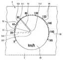
図2は、連続した複数のフレームにおいて所定の第1フレームの速度メータ画像5を示し、速度メータ画像5は、回動する指針を表す指針画像51と、指針画像51の動きの軌跡(回動軌跡)を表す軌跡画像52と、目盛を表す目盛画像54と、文字を表す文字画像55とを備える。指針画像51の色調(色相と明度の少なくともいずれか)は、例えば赤色であり、指針画像51の背景56の色調は、例えば黒色である。目盛画像54と文字画像55は、黒色の背景56を背景として白色で表示される。 FIG. 2 shows a
第1フレームの指針画像51を実線で示し、第1フレームに対して1フレーム分前の第2フレームの指針画像510を2点鎖線で示す。第1フレームの軌跡画像52が、指針画像51の動きの軌跡を表すように、第1フレームの指針画像51が表示されている第1部位と、と第2フレームの指針画像510が表示された第2部位とを結んで連続して形成される。具体的に、指針画像51の先端511と他端512が、それぞれ、第2フレームの指針画像510から回動したことにより生じる線521,522と指針画像51とによって形成される面として、扇形状で形成される。 The
第1フレームの軌跡画像52は、第2フレームの指針画像510が表示された第2部位にグラデーション部53を備え、グラデーション部53が、第2部位(指針画像510)側へ向かって指針画像51の赤色から指針画像51の背景56の黒色へ徐々に変化するグラデーションとして形成される。尚、軌跡画像52において指針画像51とグラデーション部53の間は、指針画像51の赤色で表示される。 The
以上のように、第1フレームの軌跡画像52を、第1フレームの指針画像51が表示されている第1部位と、第1フレームに対して1フレーム分前の第2フレームの指針画像510が表示された第2部位とを結んで連続して形成しているため、第2フレームと次の第1フレームの間で、指針画像51の回動動作がステップ状に飛んでいるように視認されることを抑えることができる。したがって、指針画像51の動きを円滑に視認させることができる。 As described above, the
また、グラデーション部53が、第2部位(指針画像510)側へ向かって指針画像51の赤色から背景56の黒色へ徐々に変化するグラデーションとして形成されているため、グラデーション部53は、第2部位側でより不明瞭になる第1フレームの指針画像51の残像を表現することが可能になり、軌跡画像52において指針画像51の回動を、より認識させることが可能になる。 In addition, since the
また、軌跡画像52は、指針画像51の先端511と他端512が、それぞれ、動いたことにより生じる線521,522と指針画像51とによって形成される面として形成されている。このため、軌跡画像52は、指針画像51の回動の軌跡を、より的確に表すことができる。 Further, the
次に、指針画像51と軌跡画像52の表示について、CPU3が実行する制御フローを、図3に基いて説明する。ステップS10−S50の一連の制御フローが、1フレームの画像の制御に対応する。 Next, a control flow executed by the CPU 3 for displaying the
イグニッションスイッチ7がオンされて制御フローがスタートし、ステップS10でCPU3は、速度センサ6から速度信号を取り込み、速度信号に基いて指針画像51の指示角度と前のフレームから指針画像51が回動した回動角度とを算出する。ステップS10の後に、ステップS20で、指針画像51の回動角度が零か否かを判定する。 The
ステップS20がNOの場合、即ち、指針画像51の回動角度が零でない場合、つまり、前のフレームから指針画像51が回動中の場合、ステップS30で、ステップS10で算出された指示角度と回動角度とに基いて、グラデーション部53を含めて軌跡画像52の形状を算出する。ステップS40で、ステップS10、S30で算出した指示角度と軌跡画像52の形状とに基いて、指針画像51と軌跡画像52のポリゴンデータと画像データとをセットする。 If NO in step S20, that is, if the rotation angle of the
ステップS50で、CPU3からの指示により、描画IC4は、ステップS40でセットされたポリゴンデータの各ポリゴンに画像データの各テクスチャを貼り付けて、図2に示すように、液晶パネル2に指針画像51と軌跡画像52を描画する。これにより、軌跡画像52とグラデーション部53は、ステップS30で算出した軌跡画像52の形状に基いて、ポリゴンデータの各ポリゴンの色やアルファ値(透明度)が設定されて表示される。このアルファ値により、グラデーション部53のグラデーション状態が設定される。 In step S50, in accordance with an instruction from the CPU 3, the drawing IC 4 pastes each texture of the image data on each polygon of the polygon data set in step S40, and the
ステップS50の後に、ステップS10に戻り、ステップS10−S50を、各フレーム毎に繰り返す。ステップS20がYESの場合、即ち、回動角度が零の場合、つまり、指針画像51が回動していない場合、この制御フローを終了する。 After step S50, the process returns to step S10, and steps S10 to S50 are repeated for each frame. When step S20 is YES, that is, when the rotation angle is zero, that is, when the
尚、ステップS20において、「回動角度が零か否か」を判定する代わりに、「回動角度が所定値以下か否か」を判定することも可能である。この場合、指針画像51の回動角度が所定値を超えた場合に、軌跡画像52が表示されるが、回動角度が所定値以下の回動速度が遅い場合、軌跡画像52が表示されない。ここで、軌跡画像52を表示させない場合において指針画像51の回動速度が速い場合、例えば、所定のフレームと次のフレームの間で指針画像51の回動角度が大きい場合、指針画像の回動動作がステップ状に飛んでいるように視認される。例えば、図2において、軌跡画像52を表示させない場合において第1フレームに対して1フレーム分前の第2フレームの指針画像510から第1フレームの指針画像51まで回動した場合、指針画像51の回動動作がステップ状に飛んでいるように視認され、視認者に違和感を与えるという問題が生じる。 In step S20, instead of determining whether or not the rotation angle is zero, it is also possible to determine whether or not the rotation angle is a predetermined value or less. In this case, the
これに対して、例えば、図2において、第2フレームの指針画像510が数字「60」の文字画像55近傍に位置する場合、即ち、回動角度が所定値以下の回動速度が遅い場合、指針画像51の回動動作がステップ状に飛んでいるように視認され難くなる。このため、軌跡画像52を表示させる必要がないため、回動角度が所定値以下の回動速度が遅い場合、軌跡画像52を表示させない構成とすることも可能である。 On the other hand, for example, in FIG. 2, when the
また、上述したように、アルファ値を計算してグラデーション部53を有する軌跡画像52を描画する代わりに、グラデーション部53を有する軌跡画像52を画像データとして画像データ記憶部33に記憶しておき、この画像データをポリゴンに貼り付けてグラデーション部53を有する軌跡画像52を描画することも可能である。これによっても上述と同様の効果を得ることができる。 Further, as described above, instead of calculating the alpha value and drawing the
また、図1において、ポリゴンデータ記憶部32を用いない構成とすることも可能である。この場合、ステップS30で算出される様々な軌跡画像52の形状に応じた画像データを画像データ記憶部33に記憶しておき、ステップS40で、ステップS10、S30で算出した指示角度と軌跡画像52の形状とに基いて、指針画像51と軌跡画像52の画像データをセットする。ステップS50で、描画IC4は、ステップS40でセットされた画像データを用いて、液晶パネル2に指針画像51と軌跡画像52を描画する。これによっても上述と同様の効果を得ることができる。 In FIG. 1, the polygon
以上、本実施形態による表示装置1は、指針を表す指針画像51と、指針画像51の動きの軌跡を表す軌跡画像52とを表示可能な表示パネルである液晶パネル2と、複数のフレームの指針画像51と軌跡画像52とを、連続的に切り替えて表示可能なように液晶パネル2の表示状態を制御する制御手段であるCPU3と描画IC4とを備え、複数のフレームにおいて所定の第1フレームの軌跡画像52が、第1フレームの指針画像51が表示されている第1部位と、第1フレームに対して1フレーム分前の第2フレームの指針画像510が表示された第2部位とを結んで連続して形成されている。これにより、指針画像の動きを円滑に視認させることが可能な表示装置を提供できる。 As described above, the
(第1変形例)
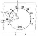
上述の例では、第1フレームの軌跡画像52において、第2フレームの指針画像510が表示された第2部位にグラデーション部53を配置したが、これに限らない。第1フレームの軌跡画像52とグラデーション部53の代わりに、図4に示すように、第1フレームの軌跡画像52Aにおいて、第2フレームの指針画像510が表示された第2部位と第1フレームの指針画像51が表示されている第1部位の両方にグラデーション部53Aを配置することも可能である。(First modification)
In the above-described example, the
第2部位(指針画像510)に配置されたグラデーション部53Aが、第2部位側へ向かって背景56の黒色から指針画像51の赤色へ徐々に変化するグラデーションとして形成され、第1部位(指針画像51)に配置されたグラデーション部53Aが、第1部位側へ向かって背景56の黒色から指針画像51の赤色へ徐々に変化するグラデーションとして形成される。 The
これにより、上述と同様の効果を得ることができると共に、軌跡画像52Aにおいて第2部位(指針画像510)と第1部位(指針画像51)とを強調しつつ、第1部位側で指針画像51とのつながり感を得ることができる。 As a result, the same effect as described above can be obtained, and the
(第2変形例)
上述の例では、グラデーション部53,53Aを、第2部位(指針画像510)と第1部位(指針画像51)に配置したが、これに限らない。(Second modification)
In the above-described example, the
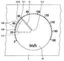
軌跡画像52,52Aとグラデーション部53,53Aの代わりに、図5に示すように、第1フレームの軌跡画像52Bにおいて外周側の円周521Bに、グラデーション部53Bを配置し、グラデーション部53Bを、円周側521Bへ向かって指針画像51の赤色から背景56の黒色へ徐々に変化するグラデーションとして形成することも可能である。これにより、上述と同様の効果を得ることができる。 Instead of the
ここで、回動する指針画像51の先端511側がより長い距離を回動するため、即ち、回動する指針画像51の先端511側が他端512側より長い距離を回動するため、先端511側の残像は、より不明瞭に、即ち、背景56側の黒色になる。このため、円周521B側を、即ち、先端511側を背景側の黒色で表示するグラデーション部53Bは、指針画像51の残像を認識させることができる。このため、円周側521Bを背景56側の黒色で表示するグラデーション部53Bは、軌跡画像52Bにおいて、指針画像51の回動を、より認識させることが可能になる。 Here, since the
(第3変形例)
上述の例では、回動する指針画像51に対して、指針画像51の回動の軌跡を表す軌跡画像52,52A,52Bを表示させたが、これに限らない。指針画像51の代わりに、例えば、図6において左右方向へ動く指針画像51Cに対して、指針画像51Cの動きの軌跡を表す軌跡画像52Cを表示させることも可能である。これに伴い、目盛画像54と文字画像55の代わりに、目盛画像54Cと文字画像55Cを、指針画像51Cが動く方向に沿って配列させる。(Third Modification)
In the above example, the
第1フレームの指針画像51Cを実線で示し、第1フレームに対して1フレーム分前の第2フレームの指針画像510Cを2点鎖線で示す。第1フレームの軌跡画像52Cが、指針画像51Cの動きの軌跡を表すように、第1フレームの指針画像51Cが表示されている第1部位と、第2フレームの指針画像510Cが表示された第2部位とを結んで連続して形成される。具体的に、指針画像51Cの先端511Cと他端512Cが、それぞれ、第2フレームの指針画像510Cから回動したことにより生じる線521C,522Cと指針画像51Cとによって形成される面として、長方形で形成される。 The pointer image 51C of the first frame is indicated by a solid line, and the
第1フレームの軌跡画像52Cは、第2フレームの指針画像510Cが表示された第2部位にグラデーション部53Cを備え、グラデーション部53Cが、第2部位(指針画像510C)側へ向かって指針画像51C赤色から指針画像51Cの背景56Cの黒色へ徐々に変化するグラデーションとして形成される。尚、軌跡画像52Cにおいて指針画像51Cとグラデーション部53Cの間は、指針画像51Cの赤色で表示される。これにより、上述と同様の効果を得ることができる。 The
なお、上述の例では、グラデーション部53,53A,53B,53Cは、軌跡画像52,52A,52B,52Cの一部であったが、軌跡画像52,52A,52B,52Cの全部とすることも可能である。例えば、図2において、指針画像51から指針510まで指針画像51の赤色から背景56の黒色へ徐々に変化するグラデーション部として形成することも可能であり、図5において、他端512側から円周521B側まで指針画像51の赤色から背景56の黒色へ徐々に変化するグラデーション部として形成することも可能である。これによっても、上述と同様の効果を得ることができる。 In the above example, the
また、上述の例では、軌跡画像52、52A、52B、52Cは、指針画像51Cの先端511、511Cと他端512、512Cが、それぞれ、動いたことにより生じる線521,521C,522,522Cと指針画像51、51Cとによって形成される面として形成されたが、これに限らない。軌跡画像が、指針画像の動きの軌跡を表すように形成される限りにおいて、指針画像の長手方向において、軌跡画像の長さを指針画像の長さより短くすることも可能である。 In the above example, the
また、上述の例では、第1フレームの軌跡画像52、52A、52B、52Cを、第1フレームの指針画像51,51Cが表示されている第1部位と、第1フレームに対して1フレーム分前の第2フレームの指針画像510,510Cが表示された第2部位とを結んで連続して形成したが、これに限らない。例えば、第1フレームの軌跡画像を、第1フレームの指針画像51,51Cが表示されている第1部位と、第2フレームに対して1フレーム分前の第3フレームの指針画像が表示された第3部位とを結んで連続して形成するようにすることも可能である。 Further, in the above-described example, the
また、液晶パネル2を、フルカラー表示をしないモノクロ液晶パネルとすることも可能である。 The
また、受光型(非発光型)の表示パネルである液晶パネル2の代わりに、発光型の表示パネルであるEL(エレクトロ・ルミネセンス)表示パネルを使用することも可能である。 Further, instead of the
また、上述した例に限らないで、これらの組み合わせや、他の種々の変形例が考えられる。 Further, the present invention is not limited to the above-described examples, and combinations thereof and other various modifications are conceivable.
1 表示装置、2 液晶パネル(表示パネル)、3 CPU(制御手段)
31 ROM、32 ポリゴンデータ記憶部、33 画像データ記憶部
34 RAM、4 描画IC(制御手段)、41 画像メモリ、5 速度メータ画像
51,51C,510,510C 指針画像、511 先端、512 他端
52,52A,52B,52C 軌跡画像
521,521C,522,522C 線、523B 円周
53,53A,53B,53C グラデーション部、54,54C 目盛画像
55,55C 文字画像、56 背景、6 速度センサ、7 イグニッションスイッチ
8 バッテリDESCRIPTION OF
31 ROM, 32 Polygon data storage unit, 33 Image
Claims (1)
Translated fromJapanese複数のフレームの前記指針画像と前記軌跡画像とを、連続的に切り替えて表示可能なように前記表示パネルの表示状態を制御する制御手段とを備え、
前記複数のフレームにおいて所定の第1フレームの前記軌跡画像は、前記第1フレームの前記指針画像が表示されている第1部位と、前記第1フレームに対して1フレーム分前の第2フレームの前記指針画像が表示された第2部位とを結んで連続して形成されており、
前記指針画像の前記動きは、前記指針画像の回動であり、
前記第1フレームの前記軌跡画像は、前記第1フレームの前記指針画像と前記第2フレームの前記指針画像とからなる扇形状を有し、且つ、前記軌跡画像において外周側の円周に、グラデーション部を備え、
前記グラデーション部は、前記円周側に向かって前記指針画像の色調から前記指針画像の背景の色調へ徐々に変化するグラデーションとして形成されていることを特徴とする表示装置。A display panel capable of displaying a pointer image representing a pointer and a locus image representing a movement locus of the pointer image;
Control means for controlling the display state of the display panel so that the pointer image and the trajectory image of a plurality of frames can be continuously switched and displayed;
In the plurality of frames, the trajectory image of a predetermined first frame includes a first portion where the pointer image of the first frame is displayed, and a second frame one frame before the first frame. It is formed continuously connecting the second part where the pointer image is displayed,
The movement of the pointer image is rotation of the pointer image,
The trajectory image ofthe first frame has a fan shape composed of the pointer image of the first frame and the pointer image of the second frame, and a gradation is formedon the outer circumference side of the trajectory image. Part
The display device, wherein the gradation portion is formed as a gradation that gradually changes from the color tone of the pointer image toward thecircumferential side from the color tone of the pointer image.
Priority Applications (4)
| Application Number | Priority Date | Filing Date | Title |
|---|---|---|---|
| JP2007273109AJP4536766B2 (en) | 2007-10-19 | 2007-10-19 | Display device |
| DE102008051749.6ADE102008051749B4 (en) | 2007-10-19 | 2008-10-15 | display device |
| CN2008101705447ACN101412374B (en) | 2007-10-19 | 2008-10-17 | Display device |
| US12/254,306US8160298B2 (en) | 2007-10-19 | 2008-10-20 | Display device |
Applications Claiming Priority (1)
| Application Number | Priority Date | Filing Date | Title |
|---|---|---|---|
| JP2007273109AJP4536766B2 (en) | 2007-10-19 | 2007-10-19 | Display device |
Publications (2)
| Publication Number | Publication Date |
|---|---|
| JP2009103473A JP2009103473A (en) | 2009-05-14 |
| JP4536766B2true JP4536766B2 (en) | 2010-09-01 |
Family
ID=40563015
Family Applications (1)
| Application Number | Title | Priority Date | Filing Date |
|---|---|---|---|
| JP2007273109AExpired - Fee RelatedJP4536766B2 (en) | 2007-10-19 | 2007-10-19 | Display device |
Country Status (4)
| Country | Link |
|---|---|
| US (1) | US8160298B2 (en) |
| JP (1) | JP4536766B2 (en) |
| CN (1) | CN101412374B (en) |
| DE (1) | DE102008051749B4 (en) |
Families Citing this family (14)
| Publication number | Priority date | Publication date | Assignee | Title |
|---|---|---|---|---|
| US8638206B2 (en)* | 2007-06-20 | 2014-01-28 | Johnson Controls Technology Company | Method of displaying a pointer on a display area of a vehicle instrument panel |
| JP5187575B2 (en)* | 2008-09-22 | 2013-04-24 | 日本精機株式会社 | Vehicle display device |
| JP5336330B2 (en) | 2009-11-20 | 2013-11-06 | 矢崎総業株式会社 | Display device |
| JP5234072B2 (en)* | 2010-09-03 | 2013-07-10 | 株式会社デンソー | Pointer display device |
| JP2013032950A (en)* | 2011-08-01 | 2013-02-14 | Denso Corp | Display device |
| JP5871739B2 (en)* | 2012-07-25 | 2016-03-01 | カルソニックカンセイ株式会社 | Vehicle display device |
| JP5900279B2 (en)* | 2012-10-17 | 2016-04-06 | 株式会社デンソー | Pointer-type instrument |
| JP6118126B2 (en)* | 2013-02-19 | 2017-04-19 | 矢崎総業株式会社 | Vehicle display device |
| JP6473434B2 (en) | 2016-10-14 | 2019-02-20 | 矢崎総業株式会社 | Display device |
| JP6543280B2 (en) | 2017-01-31 | 2019-07-10 | 矢崎総業株式会社 | Display device |
| CN109166510B (en)* | 2018-11-16 | 2021-12-03 | 黑龙江天有为电子有限责任公司 | Segment code liquid crystal screen analog pointer display device and method for simulating continuous moving of pointer |
| JP7476878B2 (en)* | 2019-03-20 | 2024-05-01 | 日本精機株式会社 | Display device |
| CN112297843B (en)* | 2020-04-21 | 2023-11-17 | 友达光电股份有限公司 | Display method and vehicle-mounted device applied to instrument panel |
| JP7709104B1 (en)* | 2023-12-26 | 2025-07-16 | 三菱自動車工業株式会社 | display device |
Family Cites Families (18)
| Publication number | Priority date | Publication date | Assignee | Title |
|---|---|---|---|---|
| CH631861GA3 (en)* | 1980-02-18 | 1982-09-15 | ||
| US4467323A (en)* | 1981-12-04 | 1984-08-21 | Bear Automotive Service Equipment Company | Engine analyzer with simulated analog meter display |
| US4570151A (en)* | 1983-01-03 | 1986-02-11 | Sigmatron Nova, Inc. | Speedometer display of simulated analog needle and odometer on electroluminescent panel |
| JPH03135726A (en)* | 1989-10-20 | 1991-06-10 | Nissan Motor Co Ltd | Display device for vehicle |
| JPH1120507A (en)* | 1997-06-27 | 1999-01-26 | Yazaki Corp | Indicator afterimage display |
| JP3459028B2 (en) | 1997-07-28 | 2003-10-20 | 矢崎総業株式会社 | Indicating instrument |
| JP2001141528A (en)* | 1999-11-17 | 2001-05-25 | Yazaki Corp | Indicating instrument with gradation display |
| JP2003137007A (en) | 2001-11-05 | 2003-05-14 | Denso Corp | Instrument for vehicle |
| JP2003262542A (en)* | 2002-03-07 | 2003-09-19 | Denso Corp | Meter |
| US6900808B2 (en)* | 2002-03-29 | 2005-05-31 | Sas Institute Inc. | Graphical data display system and method |
| WO2005120881A1 (en)* | 2004-06-07 | 2005-12-22 | Sharp Kabushiki Kaisha | Display device, vehicle, method for displaying, program for displaying and recording medium of same |
| JP2006010325A (en)* | 2004-06-22 | 2006-01-12 | Sharp Corp | Display device, instrument panel, motor vehicle and game system |
| JP2006201038A (en)* | 2005-01-20 | 2006-08-03 | Denso Corp | Display device |
| US7966123B2 (en)* | 2005-09-28 | 2011-06-21 | Denso Corporation | Display device and method for vehicle |
| CN2909183Y (en)* | 2005-12-05 | 2007-06-06 | 周明聪 | Dashboard structure that can be coded by color |
| JP4845101B2 (en)* | 2006-03-22 | 2011-12-28 | 本田技研工業株式会社 | Instrument display |
| US7874689B2 (en)* | 2006-10-03 | 2011-01-25 | Denso Corporation | Display device |
| US20110241853A1 (en)* | 2010-03-31 | 2011-10-06 | Delphi Technologies, Inc. | High-mount projection display apparatus for a vehicle |
- 2007
- 2007-10-19JPJP2007273109Apatent/JP4536766B2/ennot_activeExpired - Fee Related
- 2008
- 2008-10-15DEDE102008051749.6Apatent/DE102008051749B4/ennot_activeExpired - Fee Related
- 2008-10-17CNCN2008101705447Apatent/CN101412374B/ennot_activeExpired - Fee Related
- 2008-10-20USUS12/254,306patent/US8160298B2/ennot_activeExpired - Fee Related
Also Published As
| Publication number | Publication date |
|---|---|
| CN101412374A (en) | 2009-04-22 |
| CN101412374B (en) | 2012-01-25 |
| US8160298B2 (en) | 2012-04-17 |
| DE102008051749A1 (en) | 2009-06-25 |
| DE102008051749B4 (en) | 2016-12-29 |
| JP2009103473A (en) | 2009-05-14 |
| US20090102787A1 (en) | 2009-04-23 |
Similar Documents
| Publication | Publication Date | Title |
|---|---|---|
| JP4536766B2 (en) | Display device | |
| JP4839131B2 (en) | Graphic meter display device | |
| US8339400B2 (en) | Graphic display meter | |
| JP4375424B2 (en) | Display device | |
| US20080018597A1 (en) | Graphic meter display | |
| US10810703B2 (en) | Display device | |
| US8947345B2 (en) | Display device, and controller | |
| JP4992663B2 (en) | Display device | |
| JP4844457B2 (en) | Display device | |
| JP5372339B2 (en) | Display device | |
| JP4404135B2 (en) | Display device | |
| JP4967984B2 (en) | Vehicle display device | |
| CN107958646B (en) | display device | |
| JP2012180089A (en) | Display device | |
| JP5187575B2 (en) | Vehicle display device | |
| JP2009101861A (en) | Vehicle display device | |
| JP5105312B2 (en) | Vehicle display device | |
| JP2008275787A (en) | Display device | |
| KR101403748B1 (en) | Display apparatus | |
| JP6425084B2 (en) | Vehicle display device | |
| JP2008275923A (en) | Display device | |
| JP2018103920A (en) | Display device for vehicle | |
| JP6113127B2 (en) | Vehicle display device | |
| JP5673745B2 (en) | Display device | |
| JP2014045395A (en) | Image processing device and display device |
Legal Events
| Date | Code | Title | Description |
|---|---|---|---|
| A977 | Report on retrieval | Free format text:JAPANESE INTERMEDIATE CODE: A971007 Effective date:20090706 | |
| A131 | Notification of reasons for refusal | Free format text:JAPANESE INTERMEDIATE CODE: A131 Effective date:20090714 | |
| A521 | Request for written amendment filed | Free format text:JAPANESE INTERMEDIATE CODE: A523 Effective date:20090914 | |
| A02 | Decision of refusal | Free format text:JAPANESE INTERMEDIATE CODE: A02 Effective date:20100202 | |
| A521 | Request for written amendment filed | Free format text:JAPANESE INTERMEDIATE CODE: A523 Effective date:20100427 | |
| A521 | Request for written amendment filed | Free format text:JAPANESE INTERMEDIATE CODE: A523 Effective date:20100507 | |
| A911 | Transfer to examiner for re-examination before appeal (zenchi) | Free format text:JAPANESE INTERMEDIATE CODE: A911 Effective date:20100513 | |
| TRDD | Decision of grant or rejection written | ||
| A01 | Written decision to grant a patent or to grant a registration (utility model) | Free format text:JAPANESE INTERMEDIATE CODE: A01 Effective date:20100615 | |
| A01 | Written decision to grant a patent or to grant a registration (utility model) | Free format text:JAPANESE INTERMEDIATE CODE: A01 | |
| A61 | First payment of annual fees (during grant procedure) | Free format text:JAPANESE INTERMEDIATE CODE: A61 Effective date:20100616 | |
| FPAY | Renewal fee payment (event date is renewal date of database) | Free format text:PAYMENT UNTIL: 20130625 Year of fee payment:3 | |
| R150 | Certificate of patent or registration of utility model | Ref document number:4536766 Country of ref document:JP Free format text:JAPANESE INTERMEDIATE CODE: R150 Free format text:JAPANESE INTERMEDIATE CODE: R150 | |
| FPAY | Renewal fee payment (event date is renewal date of database) | Free format text:PAYMENT UNTIL: 20140625 Year of fee payment:4 | |
| R250 | Receipt of annual fees | Free format text:JAPANESE INTERMEDIATE CODE: R250 | |
| R250 | Receipt of annual fees | Free format text:JAPANESE INTERMEDIATE CODE: R250 | |
| R250 | Receipt of annual fees | Free format text:JAPANESE INTERMEDIATE CODE: R250 | |
| R250 | Receipt of annual fees | Free format text:JAPANESE INTERMEDIATE CODE: R250 | |
| R250 | Receipt of annual fees | Free format text:JAPANESE INTERMEDIATE CODE: R250 | |
| R250 | Receipt of annual fees | Free format text:JAPANESE INTERMEDIATE CODE: R250 | |
| R250 | Receipt of annual fees | Free format text:JAPANESE INTERMEDIATE CODE: R250 | |
| R250 | Receipt of annual fees | Free format text:JAPANESE INTERMEDIATE CODE: R250 | |
| LAPS | Cancellation because of no payment of annual fees |