JP4536319B2 - Transmitting apparatus, receiving apparatus, and wireless communication system - Google Patents
Transmitting apparatus, receiving apparatus, and wireless communication systemDownload PDFInfo
- Publication number
- JP4536319B2 JP4536319B2JP2002367213AJP2002367213AJP4536319B2JP 4536319 B2JP4536319 B2JP 4536319B2JP 2002367213 AJP2002367213 AJP 2002367213AJP 2002367213 AJP2002367213 AJP 2002367213AJP 4536319 B2JP4536319 B2JP 4536319B2
- Authority
- JP
- Japan
- Prior art keywords
- signal
- cir
- drc
- unit
- section
- Prior art date
- Legal status (The legal status is an assumption and is not a legal conclusion. Google has not performed a legal analysis and makes no representation as to the accuracy of the status listed.)
- Expired - Lifetime
Links
Images


Classifications
- H—ELECTRICITY
- H04—ELECTRIC COMMUNICATION TECHNIQUE
- H04W—WIRELESS COMMUNICATION NETWORKS
- H04W52/00—Power management, e.g. Transmission Power Control [TPC] or power classes
- H04W52/04—Transmission power control [TPC]
- H04W52/18—TPC being performed according to specific parameters
- H04W52/24—TPC being performed according to specific parameters using SIR [Signal to Interference Ratio] or other wireless path parameters
- H04W52/247—TPC being performed according to specific parameters using SIR [Signal to Interference Ratio] or other wireless path parameters where the output power of a terminal is based on a path parameter sent by another terminal
- H—ELECTRICITY
- H04—ELECTRIC COMMUNICATION TECHNIQUE
- H04W—WIRELESS COMMUNICATION NETWORKS
- H04W52/00—Power management, e.g. Transmission Power Control [TPC] or power classes
- H04W52/04—Transmission power control [TPC]
- H04W52/06—TPC algorithms
- H04W52/14—Separate analysis of uplink or downlink
- H04W52/143—Downlink power control
- H—ELECTRICITY
- H04—ELECTRIC COMMUNICATION TECHNIQUE
- H04W—WIRELESS COMMUNICATION NETWORKS
- H04W52/00—Power management, e.g. Transmission Power Control [TPC] or power classes
- H04W52/04—Transmission power control [TPC]
- H04W52/18—TPC being performed according to specific parameters
- H04W52/24—TPC being performed according to specific parameters using SIR [Signal to Interference Ratio] or other wireless path parameters
- H04W52/241—TPC being performed according to specific parameters using SIR [Signal to Interference Ratio] or other wireless path parameters taking into account channel quality metrics, e.g. SIR, SNR, CIR or Eb/lo
- H—ELECTRICITY
- H04—ELECTRIC COMMUNICATION TECHNIQUE
- H04W—WIRELESS COMMUNICATION NETWORKS
- H04W52/00—Power management, e.g. Transmission Power Control [TPC] or power classes
- H04W52/04—Transmission power control [TPC]
- H04W52/18—TPC being performed according to specific parameters
- H04W52/26—TPC being performed according to specific parameters using transmission rate or quality of service QoS [Quality of Service]
- H04W52/267—TPC being performed according to specific parameters using transmission rate or quality of service QoS [Quality of Service] taking into account the information rate
Landscapes
- Engineering & Computer Science (AREA)
- Computer Networks & Wireless Communication (AREA)
- Signal Processing (AREA)
- Quality & Reliability (AREA)
- Maintenance And Management Of Digital Transmission (AREA)
- Mobile Radio Communication Systems (AREA)
Description
Translated fromJapanese【0001】
【発明の属する技術分野】
本発明は、セルラー通信システムに用いられる送信装置、受信装置および無線通信システムに関する。
【0002】
【従来の技術】
セルラー通信システムは、1つの基地局が複数の通信端末と同時に無線通信を行うもので、近年の需要増加に伴い、伝送効率を高めることが要求されている。
【0003】
基地局から通信端末への下り回線の伝送効率を高める技術としてHDR(High Data Rate)が提案されている。HDRは、基地局が通信リソースを時間分割して各通信端末に割り振るスケジューリングを行い、さらに下り回線の回線品質に従って通信端末毎に伝送レートを設定してデータを送信する方法である。
【0004】
以下、基地局と通信端末とが、HDRにおいて無線通信を行う動作について、説明する。まず、基地局が各通信端末にパイロット信号を送信する。各通信端末は、パイロット信号に基づくCIR(希望波対干渉波比)等により下り回線の回線品質を推定し、通信可能な伝送レートを求める。そして、各通信端末は、通信可能な伝送レートに基づいて、パケット長、符号化方式および変調方式の組み合わせである通信モードを選択し、通信モードを示すデータレートコントロール(以下「DRC」という。)信号を基地局に送信する。
【0005】
なお、各システムにおける使用可能な変調方式の種類は、BPSK、QPSK、16QAM、64QAM等、予め決められている。また、各システムにおける使用可能な符号化の種類は、1/2ターボ符号、1/3ターボ符号、3/4ターボ符号等、予め決められている。そして、これらパケット長、変調方式、符号化方式の組み合わせにより、各システムにおける使用可能な伝送レートが複数定められている。各通信端末は、それらの組み合わせの中から、下り回線の現在の回線品質において最も効率よく通信を行える組み合わせを選択し、選択した通信モードを示すDRC信号を基地局に送信する。一般的にDRC信号は1〜Nの番号により表されており、番号が大きくなるほど下り回線の回線品質が良いことを示す。
【0006】
基地局は、各通信端末から送信されたDRC信号に基づいてスケジューリングを行ない、通信端末毎に伝送レートを設定し、コントロールチャネルを通して各通信端末に各通信端末への通信リソースの割り振りを示す信号を報知する。一般的に、基地局は、システムの伝送効率の向上を考慮して、下り回線の回線品質が最良の通信端末、すなわち、最も番号の大きなDRC信号を送信した通信端末に優先的に通信リソースを割り振る。
【0007】
そして、基地局は、割り振った時間において該当する通信端末に対してのみデータを送信する。例えば、時間t1を通信端末Aに割り振った場合、基地局は、時間t1においては通信端末Aに対してのみデータを送信し、通信端末A以外の通信端末に対してはデータを送信しない。
【0008】
このように、従来から、HDRにより回線品質に従って通信端末毎に伝送レートを設定し、通信可能な伝送レートが高い通信端末に優先的に通信リソースを割り振ることにより、システム全体としてデータの伝送効率を高めている。
【0009】
【発明が解決しようとする課題】
しかしながら、通信端末から基地局へ向かう上り回線の回線状況の悪化等により、通信端末が決定した通信モードが基地局において誤って受信されると、基地局はその誤った通信モードでデータを送信してしまう。通信端末では決定した通信モードと送信されたデータの通信モードとが相違するため、データを復調および復号することができない。
【0010】
また、上述したように基地局は、時間t1を通信端末Aに割り振った場合、時間t1においては通信端末Aに対してのみデータを送信し、通信端末A以外の通信端末に対してはデータを送信しない。
【0011】
以上のことから、通信端末が決定した通信モードが基地局において誤って受信されると、時間分割された通信リソースが使用されない区間が生じてしまい下り回線のスループットが低下するという問題がある。
【0012】
本発明はかかる点に鑑みてなされたものであり、下り回線の回線品質に基づいて各通信端末に通信リソースが割り振られる通信システムにおいて、下り回線のスループットの低下を防止することができる送信装置、受信装置および無線通信システムを提供することを目的とする。
【0013】
【課題を解決するための手段】
本発明の送信装置は、通信相手から受信したパイロット信号の受信品質を測定する測定手段と、複数のビットから構成され、かつ前記受信品質を示す情報を拡散する拡散手段と、拡散した前記情報を前記通信相手に送信する送信手段と、を具備し、前記拡散手段は、前記複数のビットのうち、上位のビットを下位のビットよりも拡散率の高い拡散コードで前記情報を拡散する構成を採る。
【0014】
この構成によれば、受信品質を示す情報のうち、上位のビットが誤りにくくなるため、回線のスループットの低下を防止することができる。
【0015】
本発明の受信装置は、パイロット信号を通信相手に送信する送信手段と、前記パイロット信号の受信品質を示す情報を前記通信相手から受信する受信手段と、を具備し、前記情報は複数のビットから構成されており、当該複数のビットのうち、上位のビットが下位のビットよりも拡散率の高い拡散コードで拡散されている構成を採る。
【0016】
この構成によれば、受信品質を示す情報のうち、上位のビットが誤りにくくなるため、回線のスループットの低下を防止することができる。
【0017】
本発明の無線通信システムは、第1の通信装置と第2の通信装置とを備えた無線通信システムであって、前記第1の通信装置は、前記第2の通信装置から受信したパイロット信号の受信品質を測定する測定手段と、複数のビットから構成され、かつ前記受信品質を示す情報を拡散する拡散手段と、拡散した前記情報を前記第2の通信装置に送信する送信手段と、を具備し、前記第2の通信装置は、前記パイロット信号を前記第1の通信装置に送信する送信手段と、前記パイロット信号の受信品質を示す情報を前記第1の通信装置から受信する受信手段と、を具備し、前記拡散手段は、前記複数のビットのうち、上位のビットを下位のビットよりも拡散率の高い拡散コードで前記情報を拡散する構成を採る。
【0018】
この構成によれば、受信品質を示す情報のうち、上位のビットが誤りにくくなるため、回線のスループットの低下を防止することができる。
【0050】
【発明の実施の形態】
本発明の骨子は、通信端末が、下り回線の回線品質を示す情報のうち、基地局に誤って受信された場合に下り回線のスループットが低下する可能性が高い情報ほど伝播路において誤りにくくして送信することにより、下り回線のスループットの低下を防止することである。
【0051】
以下、本発明の実施の形態について、添付図面を参照して詳細に説明する。
(実施の形態1)
上述したように、基地局は、下り回線の回線品質が最良の通信端末に優先的に通信リソースを割り振る。換言すれば、基地局は、最も番号の大きなDRC信号を選択し、その選択したDRC信号を送信した通信端末に優先的に通信リソースを割り振る。よって、基地局におけるDRC信号の選択頻度は、図1に示すようになる。図1は、基地局におけるDRC信号の選択頻度を示したグラフである。なお、この図では、DRC番号には1〜5が使用されており、番号が大きいほど回線品質が良いことを示す。
【0052】
図1に示すように、番号が大きいDRC信号ほど基地局において選択される頻度が高くなる。つまり、下り回線の回線品質が良い通信端末ほど通信リソースが割り当てられる頻度が高くなる。このような関係は、通信端末が多数存在して下り回線の回線品質が良い通信端末が存在する確率が増えることにより生じるものである。
【0053】
このように、各DRC信号の選択頻度は、回線品質に応じて相違している。つまり、下り回線の回線品質が良いことを示すDRC信号は選択される頻度が高くなる傾向にあるため、下り回線の回線品質が良いことを示すDRC信号が誤って受信されると、下り回線のスループットが低下する可能性が高い。また、下り回線の回線品質が悪いことを示すDRC信号は選択される頻度が低くなる傾向にあるため、下り回線の回線品質が悪いことを示すDRC信号が誤って受信されても、下り回線のスループットの低下に与える影響は小さい。
【0054】
そこで、本発明の実施の形態1に係る通信端末は、下り回線の回線品質が良いことを示すDRC信号ほど送信パワを高くして送信するものである。また、本発明の実施の形態1に係る基地局は、所定のしきい値より受信パワが低いDRC信号を除外して、通信リソースの割り当てを行うものである。
【0055】
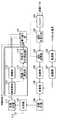
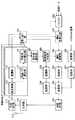
図2は、本発明の実施の形態1に係る基地局の構成を示すブロック図である。図2において、割り当て部101は、後述する復調部114で抽出されたDRC信号から後述する不使用DRC検出部116で検出されたDRC信号を除外したDRC信号に基づいて各通信端末への通信リソースの割り振りを決定する。そして、割り当て部101は、決定した通信リソースの割り振りに基づいて、バッファ102に下り送信データの出力を指示し、適応符号化部103に下り送信データの符号化方式を指示し、適応変調部104に下り送信データの変調方式を指示する。
【0056】
バッファ102は、下り送信データを保持し、割り当て部101からの指示に従って、所定の通信端末に対する下り送信データを適応符号化部103に出力する。適応符号化部103は、割り当て部101の指示に従って、バッファ102からの出力信号を符号化して適応変調部104に出力する。適応変調部104は、割り当て部102の指示に従って、適応符号化部103からの出力信号を変調して拡散部105に出力する。拡散部105は、適応変調部104からの出力信号を拡散して多重部108に出力する。
【0057】
変調部106は、パイロット信号を変調して拡散部107に出力する。拡散部107は、変調部106からの出力信号を拡散して多重部108に出力する。
【0058】
多重部108は、拡散後の下り送信データに拡散後のパイロット信号を所定の間隔で時間多重し、送信RF部109に出力する。送信RF部109は、多重部108からの出力信号の周波数を無線周波数に変換して共用器110に出力する。
【0059】
共用器110は、送信RF部109からの出力信号をアンテナ111から通信端末に無線送信する。また、共用器110は、各通信端末から無線送信され、アンテナ111に無線受信された信号を受信RF部112に出力する。
【0060】
受信RF部112は、共用器110から出力された無線周波数信号の周波数をベースバンドに変換して逆拡散部113に出力する。逆拡散部113は、ベースバンド信号を、DRC信号を拡散している拡散コードで逆拡散して復調部114および受信パワ算出部115に出力する。
【0061】
復調部114は、逆拡散部113からの出力信号を復調してDRC信号を抽出し、割り当て部101に出力する。
【0062】
受信パワ算出部115は、逆拡散後のDRC信号の受信パワを測定し、不使用DRC検出部116に出力する。不使用DRC検出部116には、後述するような所定のしきい値が設定されており、このしきい値よりも低い受信パワのDRC信号を検出し、検出結果を割り当て部101に出力する。
【0063】
なお、逆拡散部113、復調部114、受信パワ算出部115および不使用DRC検出部116は、通信端末ごとに設けられており、それぞれの復調部114から通信端末ごとのDRC信号が出力され、それぞれの不使用DRC検出部116から通信端末ごとの検出結果が出力される。
【0064】
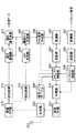
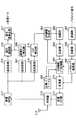
図3は、本発明の実施の形態1に係る通信端末の構成を示すブロック図である。 図3において、通信モード決定部201は、後述するCIR測定部219にて測定されたCIRに基づいて、変調方式と符号化方式の組み合わせを示す通信モードを決定して、DRC信号作成部202に出力する。また、通信モード決定部201は、決定した通信モードに基づいて、適応復調部216に下り受信データの復調方式を指示し、適応復号化部217に下り受信データの復号化方式を指示する。
【0065】
DRC信号作成部202は、通信モード決定部201から出力された通信モードに対応する番号のDRC信号を作成して、変調部203およびDRCパワ制御部205に出力する。
【0066】
変調部203は、DRC信号を変調して拡散部204に出力する。拡散部204は、変調部203からの出力信号を拡散してDRCパワ制御部205に出力する。DRCパワ制御部205は、DRC番号と送信パワとの対応関係が示されている送信パワテーブル206を参照して、後述するパイロットパワ制御部209から出力されたパイロット信号の送信パワに基づいてDRC信号の送信パワを制御し、送信パワ制御後のDRC信号を多重部210に出力する。なお、DRC信号の送信パワの具体的な制御方法については後述する。
【0067】
変調部207は、パイロット信号を変調して拡散部208に出力する。拡散部208は、変調部207からの出力信号を拡散してパイロットパワ制御部209に出力する。パイロットパワ制御部209は、パイロット信号の送信パワを制御して、送信パワ制御後のパイロット信号を多重部210に出力する。また、パイロットパワ制御部209は、パイロット信号の送信パワをDRCパワ制御部209に出力する。
【0068】
多重部210は、送信パワ制御後のDRC信号と送信パワ制御後のパイロット信号とを所定の間隔で時間多重し、送信RF部211に出力する。送信RF部211は、多重部210からの出力信号の周波数を無線周波数に変換して共用器212に出力する。
【0069】
共用器212は、送信RF部211からの出力信号をアンテナ213から基地局に無線送信する。また、共用器212は、基地局から無線送信され、アンテナ213に無線受信された信号を受信RF部214に出力する。
【0070】
受信RF部214は、共用器212から出力された無線周波数信号の周波数をベースバンドに変換し、逆拡散部215および逆拡散部218に出力する。
【0071】
逆拡散部215は、ベースバンド信号のデータ成分を逆拡散して適応復調部216に出力する。適応復調部216は、通信モード決定部201の指示に従って、逆拡散部215からの出力信号を復調して適応復号化部217に出力する。適応復号化部217は、通信モード決定部201の指示に従って、適応復調部216からの出力信号を復号して、受信データを得る。
【0072】
逆拡散部218は、ベースバンド信号のパイロット信号成分を逆拡散してCIR測定部219に出力する。CIR測定部219は、逆拡散部218から出力されたパイロット信号のCIRを測定して通信モード決定部201に出力する。
【0073】
次に、上記図2に示した基地局と上記図3に示した通信端末との間における信号の送受の手順について説明する。
【0074】
まず、通信開始時に、基地局の変調部106にてパイロット信号が変調され、拡散部107にて拡散され、多重部108に出力される。多重部108からは拡散後のパイロット信号のみが送信RF部109に出力される。拡散後のパイロット信号は、送信RF部109にて無線周波数に周波数変換され、共用器110を介してアンテナ111から各通信端末に無線送信される。
【0075】
基地局から無線送信されたパイロット信号成分のみの無線信号は、通信端末のアンテナ213に受信され、共用器212を介し、受信RF部214にてベースバンドに周波数変換される。ベースバンド信号のパイロット信号成分は、逆拡散部218にて逆拡散され、CIR測定部219に出力される。
【0076】
次に、CIR測定部219において、逆拡散部218から出力されたパイロット信号のCIRが測定され、通信モード決定部201にて、CIRに基づいて通信モードが決定される。そして、DRC信号作成部202にて、通信モードに対応する番号のDRC信号が作成される。
【0077】
DRC信号は、変調部203にて変調され、拡散部204にて拡散され、DRCパワ制御部205に出力される。DRCパワ制御部205においては、パイロットパワ制御部209から出力されるパイロット信号の送信パワと送信パワテーブル206に予め設定されているパイロット信号の送信パワとDRC信号の送信パワとの比に基づいて、DRC信号の送信パワが制御される。
【0078】
以下、送信パワテーブル206の設定内容について説明する。図4は、本発明の実施の形態1に係る通信端末が備える送信パワテーブルの内容を示す図である。
【0079】
送信パワテーブル206には、DRC番号とDRC信号の送信パワとの対応関係が示されており、DRC番号が大きくなるほど送信パワが高くなるように設定されている。なお、ここでは、DRC番号には1〜5が使用されており、番号が大きいほど下り回線の回線品質が良いことを示すものとする。つまり、送信パワテーブル206には、下り回線の回線品質が良いことを示すDRC信号ほど送信パワが高くなるように設定されている。
【0080】
上述したように下り回線の回線品質が良いことを示すDRC信号ほど基地局において選択される頻度が高くなる傾向があるため、本実施の形態では、下り回線の回線品質が良いことを示すDRC信号ほど送信パワが高くなるようにして、誤りにくくする。これにより、下り回線の回線品質が良いことを示すDRC信号が誤って受信される確率を、下り回線の回線品質が悪いことを示すDRC信号が誤って受信される確率よりも低くすることができる。換言すれば、基地局で選択される頻度が高いDRC信号が誤って受信される確率を、基地局で選択される頻度が低いDRC信号が誤って受信される確率よりも低くすることができる。
【0081】
また、送信パワテーブル206に設定されるDRC信号の送信パワは、パイロット信号の送信パワとの比によって表されている。ここでは、図4に示すように、DRC番号1〜5の真ん中に当たるDRC番号3を基準として、DRC番号3より小さい番号を示すDRC信号はパイロット信号の送信パワより低い送信パワで送信され、DRC番号3より大きい番号を示すDRC信号はパイロット信号の送信パワより高い送信パワで送信されるように設定されている。つまり、ここでは、所定の回線品質(ここでは、DRC番号3のDRC信号に対応する回線品質)よりも悪い回線品質を示すDRC信号はパイロット信号の送信パワより低い送信パワで送信され、所定の回線品質よりも良い回線品質を示すDRC信号はパイロット信号の送信パワより高い送信パワで送信されるように設定されている。
【0082】
このように、本実施の形態では、従来のDRC信号の送信パワ(つまり、ここでのパイロット信号の送信パワ)に比べ、送信パワを増加させるDRC信号と送信パワを減少させるDRC信号とを設定し、DRC信号の送信パワの増減値の合計を±0dBとすることにより、DRC信号の平均的な送信パワを従来と比べ一定に保ったまま、下り回線の回線品質が良いことを示すDRC信号ほど誤りにくくすることができる。つまり、上り回線のキャパシティを従来に比べ減少させることなく、下り回線の回線品質が良いことを示すDRC信号ほど誤りにくくすることができる。
【0083】
また、このように、下り回線の回線品質が悪いことを示すDRC信号(図4においては、DRC番号1および2のDRC信号)は従来に比べ低い送信パワで送信されるため、基地局から離れた位置に存在し、下り回線の回線品質が悪いことを示すDRC信号を送信する可能性が高い通信端末においては、消費電力を削減することができる。つまり、下り回線の回線品質が悪いことを示すDRC信号を送信する通信端末では、従来そもそも高い送信パワでDRC信号を送信していたのに対して、本実施の形態によれば、DRC信号の送信パワをその高い送信パワよりも低くすることができるので、通信端末の消費電力を大きく削減することができる。
【0084】
なお、下り回線の回線品質が悪いことを示すDRC信号は基地局において選択される頻度がそもそも低いため、このように下り回線の回線品質が悪いことを示すDRC信号を従来よりも低い送信パワで送信しても、スループットの低下に与える影響はほとんどない。
【0085】
また、本実施の形態では、上り回線の回線品質が良いことを示すDRC信号(図4においては、DRC番号4および5のDRC信号)は、従来に比べ高い送信パワで送信される。しかし、上り回線の回線品質が良いことを示すDRC信号は、基地局の比較的近くに存在する通信端末から送信される可能性が高い。また、上り回線で通常行われているパイロット信号に対する送信パワ制御により、基地局の比較的近くに存在する通信端末から送信されるパイロット信号の送信パワ(つまり、従来のDRC信号の送信パワ)は、そもそも低い。よって、上り回線の回線品質が良いことを示すDRC信号を送信する通信端末では、従来そもそも低かったDRC信号の送信パワが増加しても、DRC信号の送信パワは依然として低く消費電力は依然として低いため、電力消費に与える影響はほとんどない。
【0086】
DRCパワ制御部205においては、パイロットパワ制御部209から出力されたパイロット信号の送信パワが送信パワテーブル206に設定された比によって調節されることにより、DRC信号の送信パワが求められる。そして、DRCパワ制御部205においては、拡散部204から出力されたDRC信号の送信パワがこの求められた送信パワに制御され、送信パワ制御後のDRC信号が多重部210に出力される。具体的には、例えば、DRC信号作成部202からDRCパワ制御部205に出力されたDRC信号の番号が5である場合には、拡散部204から出力されたDRC信号の送信パワは、パイロットパワ制御部209から出力されたパイロット信号の送信パワよりも2dB低い送信パワに制御される。
【0087】
送信パワ制御後のDRC信号は、多重部210においてパイロット信号と多重され、送信RF部211にて無線周波数に周波数変換され、共用器212を介してアンテナ213から基地局に無線送信される。
【0088】
通信端末から無線送信された信号は、基地局のアンテナ111に受信され、共用器110を介して受信RF部112に入力される。受信RF部112に入力された信号は、ベースバンドに周波数変換され、逆拡散部113にてDRC信号を拡散している拡散コードで逆拡散され、復調部114および受信パワ算出部115に出力される。
【0089】
復調部114では、逆拡散部113からの出力信号が復調されてDRC信号が抽出され、割り当て部101に出力される。
【0090】
ここで、通信端末では、下り回線の回線品質が悪いことを示すDRC信号は従来に比べ低い送信パワで送信されるため、基地局では下り回線の回線品質が悪いことを示すDRC信号が誤って受信される確率が高くなる。また、誤って受信されたDRC信号に基づいて通信リソースの割り振りが行われると、上述したように、下り回線のスループットが低下する。
【0091】
そこで、受信パワ算出部115では、逆拡散後のDRC信号の受信パワが測定され、不使用DRC検出部116に出力される。不使用DRC検出部116には、下り回線の回線品質が最も悪いことを示すDRC信号(図4では、DRC番号1のDRC信号)に誤りが発生しない最低の受信パワがしきい値として予め設定されている。そして、不使用DRC検出部116では、このしきい値よりも小さい受信パワのDRC信号が検出されて、検出結果が割り当て部101に出力される。不使用DRC検出部116で検出されたDRC信号は、割り当て部101が通信リソースの割り振りを決定する際に用いないDRC信号である。
【0092】
割り当て部101では、復調部114で抽出されたDRC信号から不使用DRC検出部116で検出されたDRC信号が除外された残りのDRC信号に基づいて各通信端末への通信リソースの割り振りが決定される。
【0093】
このように、本実施の形態に係る基地局では、下り回線の回線品質が最も悪いことを示すDRC信号が誤って受信されない最低の受信パワよりも低い受信パワのDRC信号を除外する。すなわち、本実施の形態に係る基地局では、誤りが発生しやすい通知信号を除外して下り回線の通信リソースの割り振りを決定する。このため、本実施の形態に係る基地局よれば、下り回線の回線品質が悪いことを示すDRC信号が従来に比べ低い送信パワで送信されても、誤ったDRC信号に基づいて通信リソースの割り振りが決定されることを防止することができる。
【0094】
このように、本実施の形態によれば、下り回線の回線品質が良いことを示すDRC信号ほど送信パワを高くして送信するため、下り回線の回線品質が良いことを示すDRC信号ほど誤りにくくすることができ、基地局において選択される頻度の高いDRC信号の誤り発生率を低くすることができる。これにより、誤ったDRC信号に基づいて通信リソースの割り振りが決定される可能性を低くすることができるので、下り回線のスループットの低下を防止することができる。
【0095】
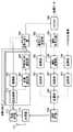
なお、本実施の形態に係る基地局を図5に示すような構成としてもよい。図5は、本発明の実施の形態1に係る基地局の別の構成を示すブロック図である。すなわち、図2に示した受信パワ算出部115および不使用DRC検出部116に代えて、尤度算出部301および不使用DRC検出部302を備えて基地局を構成するようにしてもよい。なお、以下の説明では、図2と同じ構成には図2と同じ符号を付してその詳しい説明は省略する。
【0096】
図5において、尤度算出部301は、DRC信号の確からしさの度合いを示す尤度を算出し、不使用DRC検出部302に出力する。不使用DRC検出部302には、下り回線の回線品質が最も悪いことを示すDRC信号に誤りが発生しない最低の尤度がしきい値として予め設定されている。そして、不使用DRC検出部302では、このしきい値よりも小さい尤度のDRC信号が検出されて、検出結果が割り当て部101に出力される。
【0097】
このように本実施の形態に係る基地局を図5に示すような構成とした場合にも、上記同様の効果を呈する。
【0098】
(実施の形態2)
本発明の実施の形態2に係る通信端末は、下り回線の回線品質が良いことを示すDRC信号ほど、他のDRC信号の符号語に対する最小符号間距離が大きい符号語に変換して送信するものである。
【0099】
図6は、本発明の実施の形態2に係る通信端末の構成を示すブロック図である。この図に示すように本実施の形態に係る通信端末は、図3に示す変調部203、拡散部204、DRCパワ制御部205および送信パワテーブル206に代えて、符号語選択部401、符号語テーブル402、変調部403および拡散部404を備えて構成される。なお、以下の説明では、図3と同じ構成には図3と同じ符号を付してその詳しい説明は省略する。
【0100】
符号語選択部401は、符号語テーブル402を参照して、DRC信号作成部202で作成されたDRC信号を、所定の符号語に変換して、変調部403に出力する。変調部403は、符号語を変調して拡散部404に出力する。拡散部404は、変調部403からの出力信号を拡散して多重部210に出力する。
【0101】
次に、本実施の形態に係る通信端末の動作について説明する。
まず、符号語テーブル402の設定内容について説明する。図7は、本発明の実施の形態2に係る通信端末が備える符号語テーブルの内容を示す図である。
【0102】
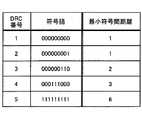
符号語テーブル402には、DRC番号とDRC信号変換後の符号語との対応関係が示されており、DRC番号が大きくなるほど、最小符号間距離が大きい符号語に変換されるように設定されている。なお、ここでは、DRC番号には1〜5が使用されており、番号が大きいほど下り回線の回線品質が良いことを示すものとする。つまり、符号語テーブル402には、下り回線の回線品質が良いことを示すDRC信号ほど、最小符号間距離が大きい符号語に変換されるように設定されている。
【0103】
ここで、符号間距離とは、各符号語間において相違するビット数であり、最小符号間距離とは、ある符号語が他のすべての符号語に対して相違する最低のビット数である。具体的には、DRC番号5のDRC信号に対応する符号語は'111111111'であり、この符号語'111111111'は、DRC番号1〜4のDRC信号に対応する符号語のいずれと比較した場合にも、最低でも6ビット相違する。よって、DRC番号5のDRC信号に対応する符号語の最小符号間距離は6である。同様に、DRC番号4のDRC信号に対応する符号語の最小符号間距離は3である。
【0104】
よって、DRC番号5のDRC信号に対応する符号語は、DRC番号4のDRC信号に対応する符号語よりも、他の符号語に誤りにくくなる。つまり、最小符号間距離が大きい符号語ほど、他の符号語に誤りにくくなる。
【0105】
符号語選択部401においては、DRC信号作成部202から出力されたDRC信号が符号語テーブル402に設定された符号語に変換されて、変調部403に出力される。具体的には、例えば、DRC信号作成部202から出力されたDRC信号が番号5のDRC信号である場合には、符号語'111111111'に変換される。
【0106】
変換後の符号語は、変調部403において変調され、拡散部404において拡散される。拡散後の符号語は、多重部210においてパイロット信号と多重され、送信RF部211にて無線周波数に周波数変換され、共用器212を介してアンテナ213から基地局に無線送信される。
【0107】
このように、本実施の形態によれば、下り回線の回線品質が良いことを示すDRC信号ほど、他のDRC信号の符号語に対する最小符号間距離が大きい符号語に変換して送信するため、下り回線の回線品質が良いことを示すDRC信号ほど誤りにくくすることができ、基地局において選択される頻度の高いDRC信号の誤り発生率を低くすることができる。これにより、誤ったDRC信号に基づいて通信リソースの割り振りが決定される可能性を低くすることができるので、下り回線のスループットの低下を防止することができる。
【0108】
また、本実施の形態によれば、DRC信号の送信パワを増加させることなく基地局において選択される頻度の高いDRC信号の誤り発生率を低くすることができるため、通信端末の消費電力を増加させることなく、誤ったDRC信号に基づいて通信リソースの割り振りが決定される可能性を低くすることができる。
【0109】
また、本実施の形態によれば、符号語の符号長を一定にしたまま各DRC信号に対応する符号語の誤りにくさを変えることができるため、基地局では、各符号長に応じて復調系統を複数備える必要がないので、基地局の装置構成を簡易にすることができる。
【0110】
(実施の形態3)
本発明の実施の形態3に係る基地局は、通信リソースの割り振りが決定される際に除外されるDRC信号の発生率に基づいてテーブル書き換えのための制御信号を通信端末へ送信し、本発明の実施の形態3に係る通信端末は、基地局から送信された制御信号に基づいて送信パワテーブルまたは符号語テーブルの内容を書き換えるものである。
【0111】
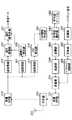
図8は、本発明の実施の形態3に係る基地局の構成を示すブロック図である。この図に示すように本実施の形態に係る基地局は、図2に示す構成に、さらに検出率算出部501、制御信号作成部502、変調部503および拡散部504を備えて構成される。なお、以下の説明では、図2と同じ構成には図2と同じ符号を付してその詳しい説明は省略する。
【0112】
図8において、検出率算出部501は、不使用DRC検出部116での検出率を算出し、制御信号作成部502に出力する。すなわち、検出率算出部501は、通信リソースの割り振りが決定される際に除外されるDRC信号の発生率を算出する。制御信号作成部502は、検出率に基づいてテーブル書き換えのための制御信号(以下「テーブル書き換え信号」という。)を作成し変調部503へ出力する。変調部503は、テーブル書き換え信号を変調し、拡散部504へ出力する。拡散部504は、変調部503からの出力信号を拡散して多重部108に出力する。
【0113】
図9は、本発明の実施の形態3に係る通信端末の構成を示すブロック図である。この図に示すように本実施の形態に係る通信端末は、図3に示す構成に、さらに逆拡散部601、復調部602およびテーブル書き換え部603を備えて構成される。なお、以下の説明では、図3と同じ構成には図3と同じ符号を付してその詳しい説明は省略する。
【0114】
図9において、逆拡散部601は、ベースバンド信号を、テーブル書き換え信号を拡散している拡散コードで逆拡散して復調部602に出力する。復調部602は、逆拡散部601からの出力信号を復調してテーブル書き換え信号を抽出して、テーブル書き換え部603へ出力する。テーブル書き換え部603は、テーブル書き換え信号に従って送信パワテーブルの内容を書き換える。
【0115】
次に、上記図8に示した基地局と上記図9に示した通信端末との間における信号の送受の手順について説明する。
【0116】
まず、基地局の検出率算出部501において、不使用DRC検出部116での検出率が算出されて、制御信号作成部502へ出力される。検出率は、例えば、所定の時間における検出回数から算出することができる。
【0117】
制御信号作成部502は、検出率の所定のしきい値が設定されており、このしきい値と検出率算出部501で算出された検出率とが比較される。そして、検出率算出部501で算出された検出率がしきい値以上となる場合には、送信パワテーブル206に設定されている送信パワをすべて増加させるように指示するテーブル書き換え信号が作成され、変調部503に出力される。つまり、制御信号作成部502では、通信リソースの割り振りが決定される際に除外されるDRC信号の発生率が所定のしきい値以上となる場合には、各DRC信号の送信パワを現在よりも一律に増加させるように指示するテーブル書き換え信号が作成される。
【0118】
テーブル書き換え信号は、変調部503にて変調され、拡散部504にて拡散され、多重部108に出力される。拡散後のテーブル書き換え信号は、多重部108にて送信データおよびパイロット信号と多重され、送信RF部109にて無線周波数に周波数変換され、共用器110を介してアンテナ111から各通信端末に無線送信される。
【0119】
基地局から無線送信された無線信号は、通信端末のアンテナ213に受信され、共用器212を介し、受信RF部214にてベースバンドに周波数変換される。ベースバンド信号は、逆拡散部601にて逆拡散され、復調部602にて復調されてテーブル書き換え信号が抽出される。抽出されたテーブル書き換え信号は、テーブル書き換え部603へ出力される。
【0120】
そしてテーブル書き換え部603によって、テーブル書き換え信号に従って送信パワテーブル206の内容が書き換えられる。つまり、テーブル書き換え部603は、送信パワテーブル206に設定されている送信パワをすべて増加させる。
【0121】
なお、上記説明では、テーブル書き換え部603が送信パワテーブル206の内容を書き換える構成としたが、本実施の形態を実施の形態2に係る通信端末に適用し、テーブル書き換え部603が図6に示す符号語テーブル402の内容を書き換える構成としてもよい。
【0122】
この場合、本実施の形態に係る基地局の制御信号作成部502は、検出率算出部501で算出された検出率がしきい値以上となる場合には、符号語テーブル402に設定されている符号語の最小符号間距離をすべて大きくするように指示するテーブル書き換え信号を作成する。つまり、制御信号作成部502は、通信リソースの割り振りが決定される際に除外されるDRC信号の発生率が所定のしきい値以上となる場合には、各DRC信号に対応する符号語の最小符号間距離を現在よりも一律に大きくするように指示するテーブル書き換え信号を作成する。そして、通信端末のテーブル書き換え部603は、テーブル書き換え信号に従って符号語テーブル402の内容を書き換える。つまり、テーブル書き換え部603は、符号語テーブル402に設定されている符号語を、現在よりも最小符号間距離をすべて大きくした符号語に書き換える。
【0123】
このように本実施の形態では、通信リソースの割り振りが決定される際に除外されるDRC信号の発生率に基づいて送信パワテーブルまたは符号語テーブルの内容を書き換える。換言すれば、本実施の形態では、通信環境の変動に対応して適応的に送信パワテーブルまたは符号語テーブルの内容を書き換える。つまり、、本実施の形態によれば、通信環境が悪化して通信リソースの割り振りが決定される際に除外されるDRC信号の発生率が所定のしきい値以上となった場合に、各DRC信号の送信パワを増加させ、または各DRC信号に対応する符号語の最小符号間距離を大きくするため、通信環境が悪化した場合にもDRC信号の誤り発生率を抑えることができる。
【0124】
なお、本実施の形態では、検出率の所定のしきい値は、通信システムが適用される環境を考慮して適宜定められる。
【0125】
また、本実施の形態では、制御信号作成部502にさらに2つ目の所定のしきい値を設定し、検出率算出部501で算出された検出率がこの2つ目のしきい値よりも小さくなる場合には、送信パワテーブル206に設定されている送信パワをすべて減少させるように指示するテーブル書き換え信号を作成するようにしてもよい。これにより、DRC信号の受信品質が過剰となる場合にはDRC信号の送信パワを下げることができるため、通信端末の消費電力を削減することができる。
【0126】
また、本実施の形態では、不使用DRC検出部116での検出率に基づいてテーブルの書き換えを行ったが、移動局から送信されたDRC信号のうち通信リソースの割り振りの決定に用いられたDRC信号の分布に基づいて、その分布が最適な分布になるようにテーブルを書き換えるようにしてもよい。この場合には、図8に示す基地局は、検出率算出部に代えて使用DRC分布判定部を備えて構成され、使用DRC分布判定部は、復調部114から出力されるDRC信号と不使用DRC検出部116から出力される検出結果とから通信リソースの割り振りの決定に用いられたDRC信号の分布を判定し、その分布を示す信号を制御信号作成部502に出力する。また、制御信号作成部502は、使用DRC分布判定部から出力された分布を示す信号に基づいて、テーブル書き換え信号を作成する。
【0127】
(実施の形態4)
本発明の実施の形態4に係る通信端末は、下り回線の回線品質が良いことを示すCIR情報ほど送信パワを高くして送信するものである。また、本発明の実施の形態4に係る基地局は、所定のしきい値より受信パワが低いCIR情報を除外して、通信リソースの割り当てを行うものである。
【0128】
上記実施の形態1では、通信端末が、CIRに基づいて通信モードを決定して、その決定した通信モードに対応するDRC信号を所定の送信パワで基地局に送信し、基地局が、DRC信号に基づいて各通信端末への通信リソースの割り振りを決定した。DRC信号は、下り回線の回線品質を示す他の情報(例えば、下り回線のCIR)に比べ非常に少ないビット数で表すことができるため、DRC信号を用いることにより、上り回線の回線使用効率を高めることができるという長所がある。一方、通信端末は、通信モードを決定してDRC信号を作成する必要があり、また、通信モード決定用のテーブルやDRC信号作成用のテーブル等を備える必要があるため、通信端末の消費電力が増大し、装置規模が大きくなってしまうという短所がある。
【0129】
そこで、本実施の形態では、通信端末が、CIR情報を所定の送信パワで基地局に送信し、基地局が、CIR情報に基づいて通信モードを決定した後、各通信端末への通信リソースの割り振りを決定する。このようにすることにより、上り回線の回線使用効率が多少低くなってしまうという短所があるが、通信端末は、通信モードを決定してDRC信号を作成する必要がなくなり、また、通信モード決定用のテーブルやDRC信号作成用のテーブル等を備える必要がなくなるため、通信端末の消費電力を削減でき、装置規模を小さくすることができるという大きな長所がある。また、本実施の形態では、基地局において複数の端末のCIR情報を比較して正確な通信モードを確実に決定することができるため、本実施の形態は、各通信端末においてCIRから通信モードを単純に決定することができない場合等に、特に有効である。
【0130】
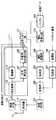
以下、本実施の形態に係る基地局および本実施の形態に係る通信端末について説明する。図10は、本発明の実施の形態4に係る基地局の構成を示すブロック図である。なお、以下の説明では、図2と同じ構成には図2と同じ符号を付してその詳しい説明は省略する。
【0131】
図10において、復調部701は、逆拡散部113からの出力信号を復調してCIR情報を含む信号(以下、「CIR信号」という。)を抽出し、割り当て部704に出力する。
【0132】
受信パワ算出部702は、逆拡散後のCIR信号の受信パワを測定し、不使用CIR検出部703に出力する。不使用CIR検出部703には、実施の形態1と同様に所定のしきい値が設定されており、このしきい値よりも低い受信パワのCIR信号を検出し、検出結果を割り当て部704に出力する。
【0133】
なお、逆拡散部113、復調部701、受信パワ算出部702および不使用CIR検出部703は、通信端末ごとに設けられており、それぞれの復調部701から通信端末ごとのCIR信号が出力され、それぞれの不使用CIR検出部703から通信端末ごとの検出結果が出力される。
【0134】
割り当て部704は、復調部701で抽出されたCIR信号から不使用CIR検出部703で検出されたCIR信号を除外したCIR信号が示すCIR情報に基づいて各通信端末への通信リソースの割り振りを決定する。そして、割り当て部704は、決定した通信リソースの割り振りに基づいて、バッファ102に下り送信データの出力を指示し、CIR情報を通信モード決定部705に出力する。
【0135】
通信モード決定部705は、割り当て部704から出力されたCIR情報に基づいて、変調方式と符号化方式の組み合わせを示す通信モードを決定して、その通信モードを示す信号を変調部706に出力する。また、通信モード決定部705は、決定した通信モードに基づいて、適応符号化部103に下り送信データの符号化方式を指示し、適応変調部104に下り送信データの変調方式を指示する。変調部706は、通信モードを示す信号を変調し、拡散部707に出力する。拡散部707は、変調部706からの出力信号を拡散して多重部108に出力する。
【0136】
図11は、本発明の実施の形態4に係る通信端末の構成を示すブロック図である。なお、以下の説明では、図3と同じ構成には図3と同じ符号を付してその詳しい説明は省略する。
【0137】
図11において、CIR情報作成部801は、CIR測定部219で測定されたCIRを示すCIR信号を作成して、変調部802およびCIR情報パワ制御部804に出力する。変調部802は、CIR信号を変調して拡散部803に出力する。拡散部803は、変調部802からの出力信号を拡散してCIR情報パワ制御部804に出力する。CIR情報パワ制御部804は、CIRの大きさとと送信パワとの対応関係が示されている送信パワテーブル805を参照して、パイロットパワ制御部209から出力されたパイロット信号の送信パワに基づいてCIR信号の送信パワを制御し、送信パワ制御後のCIR信号を多重部210に出力する。
【0138】
逆拡散部807は、ベースバンド信号を、通信モードを示す信号を拡散している拡散コードで逆拡散して、逆拡散後の信号を通信モード検出部808に出力する。通信モード検出部808は、逆拡散部807からの出力信号を復調して、通信モードを検出する。そして、通信モード検出部808は、検出した通信モードに基づいて、適応復調部216に下り受信データの復調方式を指示し、適応復号化部217に下り受信データの復号化方式を指示する。
【0139】
次に、上記図10に示した基地局と上記図11に示した通信端末との間における信号の送受の手順について説明する。
【0140】
まず、図11に示す通信端末において、CIR測定部219では、逆拡散部218から出力されたパイロット信号のCIRが測定され、CIR情報作成部801にて、CIR信号が作成される。
【0141】
CIR信号は、変調部802にて変調され、拡散部803にて拡散され、CIR情報パワ制御部804に出力される。送信パワテーブル805には、実施の形態1と同様に、CIRの大きさとCIR信号の送信パワとの対応関係が示されており、CIRが大きくなるほどCIR信号の送信パワが高くなるように設定されている。つまり、送信パワテーブル805には、実施の形態1と同様に、下り回線の回線品質が良いことを示すCIR信号ほど送信パワが高くなるように設定されている。また、送信パワテーブル805に設定されるCIR信号の送信パワは、実施の形態1と同様に、パイロット信号の送信パワとの比によって表されている。
【0142】
CIR情報パワ制御部804においては、パイロットパワ制御部209から出力されたパイロット信号の送信パワが送信パワテーブル805に設定された比によって調節されることにより、CIR信号の送信パワが求められる。そして、CIR情報パワ制御部804においては、拡散部803から出力されたCIR信号の送信パワがこの求められた送信パワに制御され、送信パワ制御後のCIR信号が多重部210に出力される。
【0143】
送信パワ制御後のCIR信号は、多重部210においてパイロット信号と多重され、送信RF部211にて無線周波数に周波数変換され、共用器212を介してアンテナ213から基地局に無線送信される。
【0144】
図10に示す基地局では、復調部701にて、逆拡散部113からの出力信号が復調されてCIR信号が抽出され、割り当て部704に出力される。受信パワ算出部702では、逆拡散後のCIR信号の受信パワが測定され、不使用CIR検出部703に出力される。不使用CIR検出部703には、実施の形態1と同様に、下り回線の回線品質が最も悪いことを示すCIR信号に誤りが発生しない最低の受信パワがしきい値として予め設定されている。そして、不使用CIR検出部703では、このしきい値よりも小さい受信パワのCIR信号が検出されて、検出結果が割り当て部704に出力される。不使用CIR検出部703で検出されたCIR信号は、割り当て部704が通信リソースの割り振りを決定する際に用いないCIR信号である。
【0145】
割り当て部704では、復調部701で抽出されたCIR信号から不使用CIR検出部703で検出されたCIR信号が除外された残りのCIR信号が示すCIRに基づいて各通信端末への通信リソースの割り振りが決定され、CIR情報が通信モード決定部705に出力される。
【0146】
通信モード決定部705では、割り当て部704から出力されたCIR情報に基づいて、通信モードが決定され、その通信モードを示す信号が変調部706に出力される。通信モードを示す信号は、変調部706にて変調され、拡散部707にて拡散され、多重部108にて送信データおよびパイロット信号と多重され、送信RF部109にて無線周波数に周波数変換され、共用器110を介してアンテナ111から通信端末に無線送信される。
【0147】
図11に示す通信端末では、逆拡散部807にて、ベースバンド信号が逆拡散され、逆拡散後の信号が通信モード検出部808に出力される。通信モード検出部808では、逆拡散部807からの出力信号が復調されて通信モードが検出され、検出された通信モードに基づいて、適応復調部216に下り受信データの復調方式が指示され、適応復号化部217に下り受信データの復号化方式が指示される。
【0148】
このように、本実施の形態によれば、実施の形態1と同様に、下り回線の回線品質が良いことを示すCIR信号ほど送信パワを高くして送信するため、基地局において使用される頻度の高いCIR情報の誤り発生率を低くすることができる。これにより、誤ったCIR情報に基づいて通信リソースの割り振りが決定される可能性を低くすることができるので、下り回線のスループットの低下を防止することができる。
【0149】
また、本実施の形態のよれば、実施の形態1と同様に、下り回線の回線品質が最も悪いことを示すCIR信号が誤って受信されない最低の受信パワよりも低い受信パワのCIR信号を除外するため、下り回線の回線品質が悪いことを示すCIR信号が従来に比べ低い送信パワで送信されても、誤ったCIR情報に基づいて通信リソースの割り振りが決定されることを防止することができる。
【0150】
なお、本実施の形態に係る基地局を図12に示すような構成としてもよい。図12は、本発明の実施の形態4に係る基地局の別の構成を示すブロック図である。すなわち、図10に示した受信パワ算出部702および不使用CIR検出部703に代えて、尤度算出部901および不使用CIR検出部902を備えて基地局を構成するようにしてもよい。なお、以下の説明では、図10と同じ構成には図10と同じ符号を付してその詳しい説明は省略する。
【0151】
図12において、尤度算出部901は、CIR信号の確からしさの度合いを示す尤度を算出し、不使用CIR検出部902に出力する。不使用CIR検出部902には、下り回線の回線品質が最も悪いことを示すCIR信号に誤りが発生しない最低の尤度がしきい値として予め設定されている。そして、不使用CIR検出部902では、このしきい値よりも小さい尤度のCIR信号が検出されて、検出結果が割り当て部704に出力される。
【0152】
このように本実施の形態に係る基地局を図12に示すような構成とした場合にも、上記同様の効果を呈する。
【0153】
(実施の形態5)
本発明の実施の形態5に係る通信端末は、下り回線の回線品質が良いことを示すCIR信号ほど、他のCIR信号の符号語に対する最小符号間距離が大きい符号語に変換して送信するものである。
【0154】
図13は、本発明の実施の形態5に係る通信端末の構成を示すブロック図である。この図に示すように本実施の形態に係る通信端末は、図11に示す変調部802、拡散部803、CIR情報パワ制御部804および送信パワテーブル805に代えて、符号語選択部1001、符号語テーブル1002、変調部1003および拡散部1004を備えて構成される。なお、以下の説明では、図11と同じ構成には図11と同じ符号を付してその詳しい説明は省略する。
【0155】
符号語選択部1001は、符号語テーブル1002を参照して、CIR情報作成部801で作成されたCIR信号を、所定の符号語に変換して、変調部1003に出力する。変調部1003は、符号語を変調して拡散部1004に出力する。拡散部1004は、変調部1003からの出力信号を拡散して多重部210に出力する。
【0156】
次に、本実施の形態に係る通信端末の動作について説明する。
符号語テーブル1002には、上記実施の形態2と同様に、CIRの大きさととCIR信号変換後の符号語との対応関係が示されており、CIRの大きさが大きくなるほど、最小符号間距離が大きい符号語にCIR信号が変換されるように設定されている。つまり、符号語テーブル1002には、下り回線の回線品質が良いことを示すCIR信号ほど、最小符号間距離が大きい符号語に変換されるように設定されている。
【0157】
符号語選択部1001においては、CIR情報作成部801から出力されたCIR信号が符号語テーブル1002に設定された符号語に変換されて、変調部1003に出力される。変換後の符号語は、変調部1003において変調され、拡散部1004において拡散される。拡散後の符号語は、多重部210においてパイロット信号と多重され、送信RF部211にて無線周波数に周波数変換され、共用器212を介してアンテナ213から基地局に無線送信される。
【0158】
このように、本実施の形態によれば、実施の形態2と同様に、下り回線の回線品質が良いことを示すCIR信号ほど、他のCIR信号の符号語に対する最小符号間距離が大きい符号語に変換して送信するため、基地局において使用される頻度の高いCIR情報の誤り発生率を低くすることができる。これにより、誤ったCIR情報に基づいて通信リソースの割り振りが決定される可能性を低くすることができるので、下り回線のスループットの低下を防止することができる。
【0159】
また、本実施の形態によれば、実施の形態2と同様に、CIR信号の送信パワを増加させることなく基地局において使用される頻度の高いCIR情報の誤り発生率を低くすることができるため、通信端末の消費電力を増加させることなく、誤ったCIR情報に基づいて通信リソースの割り振りが決定される可能性を低くすることができる。
【0160】
また、本実施の形態によれば、実施の形態2と同様に、符号語の符号長を一定にしたまま各CIR信号に対応する符号語の誤りにくさを変えることができるため、基地局では、各符号長に応じて復調系統を複数備える必要がないので、基地局の装置構成を簡易にすることができる。
【0161】
(実施の形態6)
本発明の実施の形態6〜8に係る通信端末は、CIR情報のうち変化量が大きい情報ほど伝播路において誤りにくくして送信するものである。換言すれば、本発明の実施の形態6〜8に係る通信端末は、CIR情報のうち大まかな値を示す情報ほど伝搬路において誤りにくくして送信するものである。
【0162】
ここで、「変化量が大きい情報」および「大まかな値を示す情報」とは、具体的には例えば、CIR値が少数値(例えば、8.7dB)で示される場合には、整数部分(すなわち、ここでは'8')のことである。この場合、整数部分の1単位あたりの変化量は1dBであり、少数部分の1単位あたりの変化量は0.1dBであるため、整数部分が「変化量が大きい情報」となる。したがって、基地局では、整数部分を誤って受信すると、少数部分を誤って受信した場合に比べて、誤りの度合いが大きくなってしまい、誤った通信モードが決定されてしまう可能性が高くなる。すなわち、下り回線のスループットが低下する可能性が高くなってしまう。
【0163】
また、CIR情報は、通常、限られたビット数の符号語に変換されて基地局に送信される。また、CIR情報の送信に使用できる送信パワや拡散コードの拡散率にも制限がある。よって、CIR情報全体を誤りにくくすることは限界があり、難しい。
【0164】
そこで、本発明の実施の形態6〜8では、CIR情報の送信についての上記制限内で、CIR情報のうち「変化量が大きい情報」(すなわち、「大まかな値を示す情報」)だけでも正確に受信されるように、上記制限内で「変化量が大きい情報」ほど伝播路において誤りにくくして送信する。
【0165】
以下、本発明の実施の形態6に係る通信端末について説明する。本発明の実施の形態6に係る通信端末は、CIR値のうち上位の桁の値ほど符号長が長い符号語に変換して送信するものである。
【0166】
図14は、本発明の実施の形態6に係る通信端末の構成を示すブロック図である。なお、以下の説明では、図11と同じ構成には図11と同じ符号を付して、その詳しい説明は省略する。
【0167】
図14において、CIR信号作成部1101は、CIR測定部219で測定されたCIR値を符号語に変換してCIR信号を作成し、作成したCIR信号を多重部210に出力する。この際、CIR信号作成部1101は、CIR値のうち上位の桁の値ほど符号長が長い符号語に変換してCIR信号を作成する。
【0168】
次いで、CIR信号作成部1101の構成について説明する。図15は、本発明の実施の形態6に係る通信端末のCIR信号作成部の構成を示すブロック図である。
【0169】
図15において、上位桁情報生成部1201は、CIR測定部219から出力されたCIR値のうち上位の桁の値を6ビット符号化部1203に出力する。下位桁情報生成部1202は、CIR測定部219から出力されたCIR値のうち下位の桁の値を4ビット符号化部1204に出力する。具体的には、例えばCIR測定部219から出力されたCIR値が8.7dBであった場合には、上位桁情報生成部1201は、'8'という整数部分の値を6ビット符号化部1203に出力し、下位桁情報生成部1202は、'7'という少数部分の値を4ビット符号化部1204に出力する。
【0170】
6ビット符号化部1203は、上位桁情報生成部1201から出力された値(ここでは、'8')を6ビットの符号語に変換して、6ビットの符号語を時間多重部1205に出力する。4ビット符号化部1204は、下位桁情報生成部1202から出力された値(ここでは、'7')を4ビットの符号語に変換して、4ビットの符号語を時間多重部1205に出力する。なお、ここでは、CIR値を示すのに使用できるビット数は10ビットであるものとする。
【0171】
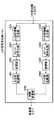
時間多重部1205は、1スロットの前半部分に6ビットの符号語を格納し、それに続く後半部分に4ビットの符号語を格納することにより、CIR値の整数部分の符号語(すなわち、上位の桁の値に対応する符号語)とCIR値の少数部分の符号語(すなわち、下位の桁の値に対応する符号語)とを時間多重する。そして、時間多重部1205は、時間多重した10ビットの符号語をCIR信号として変調部1206に出力する。なお、ここでは、10ビットで1スロットが構成され、前半6ビットでCIR値の整数部分を表し、後半4ビットでCIR値の少数部分を表すものとする。
【0172】
変調部1206は、CIR信号を変調して拡散部1207に出力する。拡散部1207は、変調部1206からの出力信号を拡散して多重部210に出力する。
【0173】
次いで、上記構成を有する通信端末の動作について説明する。
6ビット符号化部1203では、CIR値のうち上位の桁の値(ここでは、'8')が6ビットの符号語に変換される。一方、4ビット符号化部1204では、CIR値のうち下位の桁の値(ここでは、'7')が4ビットの符号語に変換される。
【0174】
6ビットで表される符号語の種類は26個であり、4ビットで表される符号語の種類は24個であるため、6ビットで表される符号語の方が各符号語間における最小符号間距離を大きくとることができる。よって、6ビットで表される符号語の方が、4ビットで表される符号語に比べて、他の符号語に誤りにくくなる。つまり、本実施の形態では、CIR値のうち上位の桁の値の方が誤りにくくなる。
【0175】
このように、本実施の形態に係る通信端末は、CIR値を示すのに使用できる10ビットという制限内で、CIR値のうち上位の桁の値ほど符号長が長い符号語に変換することにより、変化量が大きい上位の桁の値ほど誤りにくくして送信することができる。これにより、伝播路においてたとえCIR信号に誤りが発生したとしても、基地局では、CIR値のうち上位の桁の値ほど正確に受信できる確率が高くなり、CIR値の誤りの度合いを小さく抑えることができる。よって、基地局では、誤った通信モードが決定される可能性を低くすることができる。
【0176】
なお、本実施の形態においては、上位の桁の値が6ビットの符号語に変換され下位の桁の値が4ビットの符号語に変換されるとして説明した。しかし、上位の桁の値に対応する符合語のビット数が下位の桁の値に対応する符合語のビット数よりも多ければ、これらのビット数に特に制限されない。
【0177】
(実施の形態7)
本発明の実施の形態7に係る通信端末は、CIR値のうち上位の桁の値ほど送信パワを高くして送信するものである。
【0178】
本実施の形態に係る通信端末は、実施の形態6に係る通信端末と、CIR信号作成部1101の内部構成のみが相違するため、以下の説明では、CIR信号作成部1101についてのみ説明する。
【0179】
図16は、本発明の実施の形態7に係る通信端末のCIR信号作成部の構成を示すブロック図である。なお、以下の説明では、図15と同じ構成には図15と同じ符号を付して、その詳しい説明は省略する。
【0180】
図16に示すCIR信号作成部1101は、CIR測定部219で測定されたCIR値を符号語に変換した後、上位の桁の値ほど送信パワを高くしてCIR信号を作成する。
【0181】
図16において、5ビット符号化部1301は、上位桁情報生成部1201から出力された値を5ビットの符号語に変換して、5ビットの符号語を変調部1303に出力する。また、5ビット符号化部1302は、下位桁情報生成部1202から出力された値を5ビットの符号語に変換して、5ビットの符号語を変調部1304に出力する。このように、本実施の形態では、上位の桁の値も下位の桁の値も共に5ビットの符号語に変換されるため、符号語の点からは、両者間において誤りにくさに差はない。
【0182】
変調部1303は、5ビット符号化部1301から出力された符号語を変調して、上位桁拡散部1305に出力する。また、変調部1304は、5ビット符号化部1302から出力された符号語を変調して、下位桁拡散部1306に出力する。
【0183】
上位桁拡散部1305は、変調部1303からの出力信号を拡散して、上位桁パワ制御部1307に出力する。また、下位桁拡散部1306は、変調部1304からの出力信号を拡散して、下位桁パワ制御部1308に出力する。この際、上位桁拡散部1305と下位桁拡散部1306とは、拡散率が同じで違う種類の拡散コードを使用してそれぞれ拡散処理を行う。つまり、CIR値の上位の桁の値と下位の桁の値とは、拡散率が同じで違う種類の拡散コードで拡散される。
【0184】
上位桁パワ制御部1307は、パイロットパワ制御部209から出力されたパイロット信号の送信パワに基づいて、CIR値の上位の桁の値を示す信号の送信パワを制御し、送信パワ制御後の信号をコード多重部1309に出力する。また、下位桁パワ制御部1308は、パイロットパワ制御部209から出力されたパイロット信号の送信パワに基づいて、CIR値の下位の桁の値を示す信号の送信パワを制御し、送信パワ制御後の信号をコード多重部1309に出力する。なお、送信パワの具体的な制御方法は後述する。
【0185】
コード多重部1309は、CIR値の上位の桁の値を示す信号と下位の桁の値を示す信号とを同一時間帯で多重する。つまり、コード多重部1309は、上位の桁の値を示す信号と下位の桁の値を示す信号とをコード多重する。
【0186】
次いで、上記構成を有する通信端末の動作について説明する。
上位桁パワ制御部1307では、CIR値の上位の桁の値を示す信号が、パイロット信号の送信パワよりも所定の値だけ高い送信パワに制御される。また、下位桁パワ制御部1308では、CIR値の下位の桁の値を示す信号が、パイロット信号の送信パワよりも所定の値だけ低い送信パワに制御される。つまり、CIR値のうち上位の桁の値ほど送信パワが高くなる。
【0187】
このように、本実施の形態に係る通信端末は、CIR値のうち上位の桁の値ほど送信パワを高くして送信することにより、変化量が大きい上位の桁の値ほど誤りにくくして送信することができる。これにより、伝播路においてたとえCIR信号に誤りが発生したとしても、基地局では、CIR値のうち上位の桁の値ほど正確に受信できる確率が高くなり、CIR値の誤りの度合いを小さく抑えることができる。よって、基地局では、誤った通信モードが決定される可能性を低くすることができる。
【0188】
また、本実施の形態では、従来のCIR信号の送信パワ(つまり、ここでのパイロット信号の送信パワ)に比べ、上位の桁の値については送信パワを高くし、下位の桁の値については上位の桁の値について高くした分だけ送信パワを低くして、送信パワの増減値の合計を±0dBとすることにより、CIR信号全体の送信パワを従来のCIR信号の送信パワと同一に保つようにした。よって、本実施の形態によれば、CIR信号の送信パワを従来と同一に保ったまま、上位の桁の値ほど誤りにくくして送信することができる。つまり、上り回線のキャパシティを従来に比べ減少させることなく、上位の桁の値ほど誤りにくくして送信することができる。
【0189】
(実施の形態8)
本発明の実施の形態8に係る通信端末は、CIR値のうち上位の桁の値ほど拡散率の高い拡散コードで拡散して送信するものである。
【0190】
本実施の形態に係る通信端末は、実施の形態6および7に係る通信端末と、CIR信号作成部1101の内部構成のみが相違するため、以下の説明では、CIR信号作成部1101についてのみ説明する。
【0191】
図17は、本発明の実施の形態8に係る通信端末のCIR信号作成部の構成を示すブロック図である。なお、以下の説明では、図15または図16と同じ構成には図15または図16と同じ符号を付して、その詳しい説明は省略する。
【0192】
図17に示すCIR信号作成部1101は、CIR測定部219で測定されたCIR値を符号語に変換した後、上位の桁の値ほど拡散率の高い拡散コードで拡散してCIR信号を作成する。
【0193】
図17において、上位桁拡散部1401は、変調部1303からの出力信号を拡散して、時間多重部1205に出力する。また、下位桁拡散部1402は、変調部1304からの出力信号を拡散して、時間多重部1205に出力する。この際、上位桁拡散部1401は、下位桁拡散部1402で使用されるのと同じ種類で、かつ下位桁拡散部1402での拡散率よりも高い拡散率の拡散コードで拡散処理を行う。つまり、CIR値の上位の桁の値は、下位の桁の値よりも高い拡散率で拡散される。これにより、上位の桁の値ほど伝搬路において誤りにくくなる。
【0194】
このように、本実施の形態に係る通信端末は、CIR値のうち上位の桁の値ほど拡散率を高くして送信することにより、変化量が大きい上位の桁の値ほど誤りにくくして送信することができる。これにより、伝播路においてたとえCIR信号に誤りが発生したとしても、基地局では、CIR値のうち上位の桁の値ほど正確に受信できる確率が高くなり、CIR値の誤りの度合いを小さく抑えることができる。よって、基地局では、誤った通信モードが決定される可能性を低くすることができる。
【0195】
また、本実施の形態では、従来のCIR信号の拡散率に比べ、上位の桁の値については拡散率を高くし、下位の桁の値については上位の桁の値について高くした分だけ拡散率を低くする。このようにして、1スロットで送れるデータ量を従来のCIR信号と同等に保つようにした。よって、本実施の形態によれば、1スロットで送れるデータ量を減少させることなく、上位の桁の値ほど誤りにくくして送信することができる。
【0196】
なお、上記実施の形態1に係る通信端末と上記実施の形態2に係る通信端末とを組み合わせて実施することも可能である。また、上記実施の形態4に係る通信端末と上記実施の形態5に係る通信端末とを組み合わせて実施することも可能である。また、上記実施の形態6〜8に係る通信端末をそれぞれ組み合わせて実施することも可能である。また、上記実施の形態4に係る通信端末が備える送信パワテーブルおよび上記実施の形態5に係る通信端末が備える符号語テーブルを、上記実施の形態3と同様にして、基地局からの制御信号に基づいて適宜書き換えることも可能である。
【0197】
また、上記実施の形態1〜8では、パイロット信号が時間多重される場合について説明したが、上記実施の形態1〜8はこれに限られるものではなく、パイロット信号がコード多重される場合にも適用可能なものである。
【0198】
また、上記実施の形態1〜8では、パイロット信号の受信品質を示す値としてCIRを用いたが、これに限られるものではなく、受信品質を示せる値であればいかなる値を用いても構わない。
【0199】
また、上記実施の形態1〜5では、不使用DRC検出部および不使用CIR検出部に設定される所定のしきい値を固定値としたが、DRC信号の誤り率やCIR信号の誤り率に応じてしきい値を適応的に変化させる構成としてもよい。
【0200】
また、上記実施の形態6〜8では、各符号語を多重する際には、時間多重およびコード多重のどちらを用いて多重してもよい。
【0201】
また、上記実施の形態6〜8では、整数部分1桁、少数部分1桁で表されるCIR値を一例に挙げて説明した。しかし、これに限られるものではなく、上記実施の形態6〜8は、複数の桁で表されるCIR値についてすべて実施可能なものである。
【0202】
また、上記実施の形態6〜8では、CIR値の上位の桁の値を「変化量が大きい情報」として説明した。しかし、「変化量が大きい情報」は、必ずしも桁の大きさと対応するものではない。例えば、まず2dBづつ変化する値で0dB,2dB,4dB,6dB…と大まかな値を示し、その大まかな値に対し1dBの増加の有無を示す情報を付加してCIR値を整数で表す方法を採る場合には、2dBづつ変化する値が「変化量が大きい情報」となる。この方法では、例えば7dBのCIR値を表す場合には、6dBを示す情報と1dBの増加が有ることを示す情報との2つの情報が含まれたCIR信号が基地局に送信される。この際通信端末装置は、上記実施の形態6〜8と同様にして、6dBを示す情報を1dBの増加が有ることを示す情報よりも誤りにくくして送信する。
【0203】
【発明の効果】
以上説明したように、本発明によれば、下り回線の回線品質に基づいて各通信端末に通信リソースが割り振られる通信システムにおいて、下り回線のスループットの低下を防止することができる。
【図面の簡単な説明】
【図1】基地局におけるDRC信号の選択頻度を示したグラフ
【図2】本発明の実施の形態1に係る基地局の構成を示すブロック図
【図3】本発明の実施の形態1に係る通信端末の構成を示すブロック図
【図4】本発明の実施の形態1に係る通信端末が備える送信パワテーブルの内容を示す図
【図5】本発明の実施の形態1に係る基地局の別の構成を示すブロック図
【図6】本発明の実施の形態2に係る通信端末の構成を示すブロック図
【図7】本発明の実施の形態2に係る通信端末が備える符号語テーブルの内容を示す図
【図8】本発明の実施の形態3に係る基地局の構成を示すブロック図
【図9】本発明の実施の形態3に係る通信端末の構成を示すブロック図
【図10】本発明の実施の形態4に係る基地局の構成を示すブロック図
【図11】本発明の実施の形態4に係る通信端末の構成を示すブロック図
【図12】本発明の実施の形態4に係る基地局の別の構成を示すブロック図
【図13】本発明の実施の形態5に係る通信端末の構成を示すブロック図
【図14】本発明の実施の形態6に係る通信端末の構成を示すブロック図
【図15】本発明の実施の形態6に係る通信端末のCIR信号作成部の構成を示すブロック図
【図16】本発明の実施の形態7に係る通信端末のCIR信号作成部の構成を示すブロック図
【図17】本発明の実施の形態8に係る通信端末のCIR信号作成部の構成を示すブロック図
【符号の説明】
101,704 割り当て部
102 バッファ
103 適応符号化部
104 適応変調部
105,107,204,208,704,504,707,803,1004 拡散部
106,203,207,403,503,706,802,1003 変調部
108,210 多重部
113,215,218,601 逆拡散部
114,602,701 復調部
115,702 受信パワ算出部
116,302 不使用DRC検出部
201,705 通信モード決定部
202 DRC信号作成部
205 DRCパワ制御部
206,805 送信パワテーブル
209 パイロットパワ制御部
216 適応復調部
217 適応復号化部
219 CIR測定部
301,901 尤度算出部
401,1001 符号語選択部
402,1002 符号語テーブル
501 検出率算出部
502 制御信号作成部
603 テーブル書き換え部
703,902 不使用CIR検出部
801 CIR情報作成部
804 CIR情報パワ制御部
1101 CIR信号作成部
1201 上位桁情報生成部
1202 下位桁情報生成部
1203 6ビット符号化部
1204 4ビット符号化部
1305,1401 上位桁拡散部
1306,1402 下位桁拡散部
1307 上位桁パワ制御部
1308 下位桁パワ制御部[0001]
BACKGROUND OF THE INVENTION
The present invention is used in a cellular communication system.Transmitting apparatus, receiving apparatus, and wireless communication systemAbout.
[0002]
[Prior art]
In the cellular communication system, one base station performs wireless communication simultaneously with a plurality of communication terminals, and with the recent increase in demand, it is required to increase transmission efficiency.
[0003]
HDR (High Data Rate) has been proposed as a technique for improving the transmission efficiency of a downlink from a base station to a communication terminal. HDR is a method in which a base station performs scheduling for allocating communication resources to each communication terminal and assigns the communication resources to each communication terminal, and further sets a transmission rate for each communication terminal according to downlink channel quality and transmits data.
[0004]
Hereinafter, an operation in which the base station and the communication terminal perform wireless communication in HDR will be described. First, the base station transmits a pilot signal to each communication terminal. Each communication terminal estimates a downlink channel quality by CIR (desired wave-to-interference wave ratio) based on a pilot signal and obtains a transmission rate at which communication is possible. Each communication terminal selects a communication mode that is a combination of a packet length, an encoding scheme, and a modulation scheme based on a communicable transmission rate, and data rate control (hereinafter referred to as “DRC”) indicating the communication mode. Send the signal to the base station.
[0005]
Note that the types of modulation schemes that can be used in each system are determined in advance, such as BPSK, QPSK, 16QAM, and 64QAM. The types of encoding that can be used in each system are determined in advance, such as 1/2 turbo code, 1/3 turbo code, 3/4 turbo code, and the like. A plurality of transmission rates that can be used in each system are determined by a combination of the packet length, the modulation method, and the coding method. Each communication terminal selects a combination capable of performing communication most efficiently in the current channel quality of the downlink from the combinations, and transmits a DRC signal indicating the selected communication mode to the base station. In general, DRC signals are represented by
[0006]
The base station performs scheduling based on the DRC signal transmitted from each communication terminal, sets a transmission rate for each communication terminal, and transmits a signal indicating allocation of communication resources to each communication terminal to each communication terminal through a control channel. Inform. In general, in consideration of improving the transmission efficiency of the system, the base station preferentially allocates communication resources to the communication terminal with the best downlink channel quality, that is, the communication terminal that has transmitted the DRC signal with the largest number. Allocate.
[0007]
Then, the base station transmits data only to the corresponding communication terminal at the allocated time. For example, when time t1 is allocated to communication terminal A, the base station transmits data only to communication terminal A at time t1, and does not transmit data to communication terminals other than communication terminal A.
[0008]
Thus, conventionally, by setting a transmission rate for each communication terminal according to channel quality by HDR and preferentially allocating communication resources to communication terminals having a high communication rate, data transmission efficiency can be improved as a whole system. It is increasing.
[0009]
[Problems to be solved by the invention]
However, if the communication mode determined by the communication terminal is erroneously received at the base station due to deterioration of the line condition of the uplink from the communication terminal to the base station, the base station transmits data in the erroneous communication mode. End up. In the communication terminal, since the determined communication mode is different from the communication mode of the transmitted data, the data cannot be demodulated and decoded.
[0010]
Further, as described above, when time t1 is allocated to communication terminal A, the base station transmits data only to communication terminal A at time t1, and transmits data to communication terminals other than communication terminal A. Do not send.
[0011]
From the above, when the communication mode determined by the communication terminal is erroneously received at the base station, there is a problem that a section in which the time-division communication resources are not used is generated and the downlink throughput is reduced.
[0012]
The present invention has been made in view of the above points, and can prevent a decrease in downlink throughput in a communication system in which communication resources are allocated to each communication terminal based on downlink channel quality.Transmitting apparatus, receiving apparatus, and wireless communication systemThe purpose is to provide.
[0013]
[Means for Solving the Problems]
The transmitting apparatus of the present invention comprises a measuring means for measuring the reception quality of a pilot signal received from a communication partner, and information comprising the plurality of bits and indicating the reception quality.diffusionDodiffusionMeans,diffusionTransmitting means for transmitting the information to the communication partner, anddiffusionThe means is a high-order bit among the plurality of bits.TheThan the lower bitsA spreading code with a high spreading factorThe informationdiffusionThe structure to do is taken.
[0014]
According to this configuration,Of the information indicating the reception quality, the higher-order bits are less likely to be erroneous, so that a reduction in line throughput can be prevented.
[0015]
The receiving apparatus of the present invention comprises transmitting means for transmitting a pilot signal to a communication partner, and receiving means for receiving information indicating reception quality of the pilot signal from the communication partner, wherein the information is composed of a plurality of bits. Among the multiple bits, the upper bit is higher than the lower bit.Spread with spreading code with high spreading factorTake the configuration that is.
[0016]
According to this configuration,Of the information indicating the reception quality, the higher-order bits are less likely to be erroneous, so that a reduction in line throughput can be prevented.
[0017]
The wireless communication system of the present invention is a wireless communication system including a first communication device and a second communication device, wherein the first communication device receives a pilot signal received from the second communication device. Measuring means for measuring the reception quality, and information composed of a plurality of bits and indicating the reception qualitydiffusionDodiffusionMeans,diffusionTransmitting means for transmitting the information to the second communication apparatus, wherein the second communication apparatus transmits the pilot signal to the first communication apparatus; and Receiving means for receiving information indicating reception quality from the first communication device, anddiffusionThe means is a high-order bit among the plurality of bits.TheThan the lower bitsA spreading code with a high spreading factorThe informationdiffusionThe structure to do is taken.
[0018]
According to this configuration,Of the information indicating the reception quality, the higher-order bits are less likely to be erroneous, so that a reduction in line throughput can be prevented.
[0050]
DETAILED DESCRIPTION OF THE INVENTION
The essence of the present invention is that, among the information indicating the downlink channel quality, the communication terminal is less likely to make an error in the propagation path as the information that is likely to decrease the downlink throughput when it is erroneously received by the base station. Is transmitted to prevent a decrease in downlink throughput.
[0051]
Hereinafter, embodiments of the present invention will be described in detail with reference to the accompanying drawings.
(Embodiment 1)
As described above, the base station preferentially allocates communication resources to communication terminals with the best downlink channel quality. In other words, the base station selects the DRC signal having the largest number, and preferentially allocates communication resources to the communication terminal that has transmitted the selected DRC signal. Therefore, the DRC signal selection frequency in the base station is as shown in FIG. FIG. 1 is a graph showing DRC signal selection frequency in a base station. In this figure,
[0052]
As shown in FIG. 1, a DRC signal with a larger number has a higher frequency of selection at the base station. That is, the frequency with which communication resources are allocated increases as the communication terminal has better downlink channel quality. Such a relationship is caused by an increase in the probability that there are many communication terminals and there are communication terminals with good downlink channel quality.
[0053]
Thus, the selection frequency of each DRC signal is different according to the line quality. In other words, since the DRC signal indicating that the downlink channel quality is good tends to be selected more frequently, if a DRC signal indicating that the downlink channel quality is good is received by mistake, There is a high possibility that the throughput will decrease. In addition, since DRC signals indicating that the downlink channel quality is poor tend to be selected, even if a DRC signal indicating that the downlink channel quality is bad is received erroneously, The impact on throughput reduction is small.
[0054]
Therefore, the communication terminal according to
[0055]
FIG. 2 is a block diagram showing the configuration of the base station according to
[0056]
[0057]
[0058]
Multiplexing
[0059]
The
[0060]
The
[0061]
[0062]
Reception
[0063]
The
[0064]
FIG. 3 is a block diagram showing a configuration of the communication terminal according to
[0065]
DRC
[0066]
[0067]
[0068]
Multiplexing
[0069]
The
[0070]
[0071]
[0072]
The
[0073]
Next, a signal transmission / reception procedure between the base station shown in FIG. 2 and the communication terminal shown in FIG. 3 will be described.
[0074]
First, at the start of communication, a pilot signal is modulated by
[0075]
A radio signal including only a pilot signal component wirelessly transmitted from the base station is received by the
[0076]
Next,
[0077]
The DRC signal is modulated by
[0078]
Hereinafter, the setting contents of the transmission power table 206 will be described. FIG. 4 is a diagram showing the contents of the transmission power table provided in the communication terminal according to
[0079]
The transmission power table 206 shows the correspondence between the DRC number and the transmission power of the DRC signal, and is set so that the transmission power increases as the DRC number increases. Here,
[0080]
As described above, the DRC signal indicating that the downlink channel quality is good tends to be selected more frequently in the base station. Therefore, in the present embodiment, the DRC signal indicating that the downlink channel quality is good. The transmission power is increased so that errors are less likely to occur. Thereby, the probability that the DRC signal indicating that the downlink channel quality is good is erroneously received can be made lower than the probability that the DRC signal indicating that the downlink channel quality is bad is erroneously received. . In other words, the probability that a DRC signal that is frequently selected by the base station is erroneously received can be lower than the probability that a DRC signal that is frequently selected by the base station is erroneously received.
[0081]
Further, the transmission power of the DRC signal set in the transmission power table 206 is represented by a ratio with the transmission power of the pilot signal. Here, as shown in FIG. 4, with reference to
[0082]
As described above, in the present embodiment, the DRC signal for increasing the transmission power and the DRC signal for decreasing the transmission power are set as compared with the conventional transmission power of the DRC signal (that is, the transmission power of the pilot signal here). Then, by setting the total increase / decrease value of the transmission power of the DRC signal to be ± 0 dB, a DRC signal indicating that the channel quality of the downlink is good while keeping the average transmission power of the DRC signal constant compared to the conventional case. It can be made less prone to errors. That is, the DRC signal indicating that the downlink channel quality is good can be made less susceptible to errors without reducing the uplink capacity compared to the conventional one.
[0083]
Also, as described above, the DRC signal indicating that the downlink channel quality is poor (in FIG. 4, the DRC signals of
[0084]
Note that since the DRC signal indicating that the downlink channel quality is poor is selected at the base station in the first place, the DRC signal indicating that the downlink channel quality is poor is transmitted at a lower transmission power than the conventional one. Even if it is transmitted, there is almost no influence on the decrease in throughput.
[0085]
Further, in the present embodiment, DRC signals (DRC signals with
[0086]
The DRC
[0087]
The DRC signal after transmission power control is multiplexed with the pilot signal in
[0088]
A signal wirelessly transmitted from the communication terminal is received by the
[0089]
[0090]
Here, in the communication terminal, since the DRC signal indicating that the downlink channel quality is poor is transmitted with lower transmission power than the conventional one, the base station erroneously outputs the DRC signal indicating that the downlink channel quality is poor. The probability of receiving is increased. In addition, when communication resources are allocated based on the DRC signal received in error, the downlink throughput decreases as described above.
[0091]
Therefore, reception
[0092]
In allocating
[0093]
As described above, the base station according to the present embodiment excludes a DRC signal having a reception power lower than the lowest reception power at which the DRC signal indicating that the downlink channel quality is the worst is not erroneously received. That is, the base station according to the present embodiment determines the allocation of downlink communication resources by excluding notification signals that are likely to cause errors. For this reason, according to the base station according to the present embodiment, even when a DRC signal indicating that the downlink channel quality is poor is transmitted with lower transmission power than in the prior art, communication resource allocation is performed based on the erroneous DRC signal. Can be prevented from being determined.
[0094]
As described above, according to the present embodiment, a DRC signal indicating that the downlink channel quality is good is transmitted with a higher transmission power. Therefore, a DRC signal indicating that the downlink channel quality is good is less likely to be erroneous. It is possible to reduce the error rate of DRC signals that are frequently selected at the base station. As a result, it is possible to reduce the possibility that communication resource allocation is determined based on an erroneous DRC signal, thereby preventing a decrease in downlink throughput.
[0095]
The base station according to the present embodiment may be configured as shown in FIG. FIG. 5 is a block diagram showing another configuration of the base station according to
[0096]
In FIG. 5, the
[0097]
Thus, even when the base station according to the present embodiment is configured as shown in FIG. 5, the same effects as described above are exhibited.
[0098]
(Embodiment 2)
The communication terminal according to
[0099]
FIG. 6 is a block diagram showing a configuration of a communication terminal according to
[0100]
The codeword selection unit 401 refers to the codeword table 402, converts the DRC signal created by the DRC
[0101]
Next, the operation of the communication terminal according to the present embodiment will be described.
First, the setting contents of the codeword table 402 will be described. FIG. 7 is a diagram showing the contents of the codeword table provided in the communication terminal according to
[0102]
The codeword table 402 shows the correspondence between the DRC number and the codeword after the DRC signal conversion, and the codeword table 402 is set so that the larger the DRC number is, the larger the minimum code distance is. Yes. Here,
[0103]
Here, the intercode distance is the number of bits that differ between the codewords, and the minimum intercode distance is the minimum number of bits that a codeword differs from all other codewords. Specifically, the code word corresponding to the DRC signal with
[0104]
Therefore, the code word corresponding to the DRC signal of
[0105]
In codeword selection section 401, the DRC signal output from DRC
[0106]
The converted codeword is modulated by modulation section 403 and spread by spreading section 404. The spread codeword is multiplexed with the pilot signal in
[0107]
Thus, according to the present embodiment, the DRC signal indicating that the downlink channel quality is good is converted into a codeword having a larger minimum code distance with respect to the codeword of the other DRC signal, and transmitted. A DRC signal indicating that the downlink channel quality is good can be made more unlikely to be an error, and an error occurrence rate of a DRC signal that is frequently selected in the base station can be reduced. As a result, it is possible to reduce the possibility that communication resource allocation is determined based on an erroneous DRC signal, thereby preventing a decrease in downlink throughput.
[0108]
Further, according to the present embodiment, it is possible to reduce the error occurrence rate of a DRC signal that is frequently selected in the base station without increasing the transmission power of the DRC signal, thereby increasing the power consumption of the communication terminal. Without making it possible, it is possible to reduce the possibility that communication resource allocation is determined based on an erroneous DRC signal.
[0109]
Further, according to the present embodiment, since the code word error corresponding to each DRC signal can be changed with a constant code word code length, the base station demodulates according to each code length. Since it is not necessary to provide a plurality of systems, the base station apparatus configuration can be simplified.
[0110]
(Embodiment 3)
The base station according to
[0111]
FIG. 8 is a block diagram showing the configuration of the base station according to
[0112]
In FIG. 8, the detection
[0113]
FIG. 9 is a block diagram showing a configuration of a communication terminal according to
[0114]
In FIG. 9, the
[0115]
Next, a signal transmission / reception procedure between the base station shown in FIG. 8 and the communication terminal shown in FIG. 9 will be described.
[0116]
First, in the base station detection
[0117]
The control
[0118]
The table rewrite signal is modulated by
[0119]
A radio signal wirelessly transmitted from the base station is received by the
[0120]
The
[0121]
In the above description, the
[0122]
In this case, control
[0123]
Thus, in the present embodiment, the contents of the transmission power table or codeword table are rewritten based on the DRC signal generation rate that is excluded when communication resource allocation is determined. In other words, in the present embodiment, the contents of the transmission power table or codeword table are rewritten adaptively in response to changes in the communication environment. That is, according to the present embodiment, when the communication environment deteriorates and the occurrence rate of DRC signals excluded when communication resource allocation is determined exceeds a predetermined threshold, each DRC Since the signal transmission power is increased or the minimum inter-code distance of the codeword corresponding to each DRC signal is increased, the error rate of the DRC signal can be suppressed even when the communication environment is deteriorated.
[0124]
In the present embodiment, the predetermined threshold value of the detection rate is appropriately determined in consideration of the environment where the communication system is applied.
[0125]
Further, in the present embodiment, a second predetermined threshold value is further set in the control
[0126]
Further, in this embodiment, the table is rewritten based on the detection rate in the unused
[0127]
(Embodiment 4)
The communication terminal according to
[0128]
In
[0129]
Therefore, in this embodiment, the communication terminal transmits CIR information to the base station with a predetermined transmission power, and after the base station determines the communication mode based on the CIR information, the communication resource of each communication terminal is determined. Determine allocation. By doing so, there is a disadvantage that the line use efficiency of the uplink is somewhat lowered, but the communication terminal does not need to determine the communication mode and create the DRC signal, and for communication mode determination Therefore, there is no need to provide a table for creating a DRC signal, a table for creating a DRC signal, and the like, so that power consumption of the communication terminal can be reduced and the apparatus scale can be reduced. Also, in this embodiment, since the base station can compare CIR information of a plurality of terminals and determine an accurate communication mode with certainty, this embodiment changes the communication mode from the CIR in each communication terminal. This is particularly effective when it cannot be determined simply.
[0130]
Hereinafter, the base station according to the present embodiment and the communication terminal according to the present embodiment will be described. FIG. 10 is a block diagram showing a configuration of a base station according to
[0131]
In FIG. 10, the
[0132]
The reception
[0133]
The
[0134]
The
[0135]
Communication
[0136]
FIG. 11 is a block diagram showing a configuration of a communication terminal according to
[0137]
In FIG. 11, the CIR
[0138]
[0139]
Next, a signal transmission / reception procedure between the base station shown in FIG. 10 and the communication terminal shown in FIG. 11 will be described.
[0140]
First, in the communication terminal shown in FIG. 11,
[0141]
The CIR signal is modulated by
[0142]
The CIR information
[0143]
The CIR signal after transmission power control is multiplexed with the pilot signal in
[0144]
In the base station shown in FIG. 10, the
[0145]
The
[0146]
Communication
[0147]
In the communication terminal shown in FIG. 11, the
[0148]
Thus, according to the present embodiment, as in the first embodiment, the CIR signal indicating that the channel quality of the downlink is good is transmitted with a higher transmission power, and therefore the frequency used in the base station. It is possible to reduce the error occurrence rate of high CIR information. As a result, it is possible to reduce the possibility that communication resource allocation is determined based on erroneous CIR information, and it is possible to prevent a decrease in downlink throughput.
[0149]
Further, according to the present embodiment, as in the first embodiment, the CIR signal having a lower reception power than the lowest reception power in which the CIR signal indicating that the downlink channel quality is the worst is not erroneously received is excluded. Therefore, even when a CIR signal indicating that the downlink channel quality is poor is transmitted with lower transmission power than in the past, it is possible to prevent communication resource allocation from being determined based on erroneous CIR information. .
[0150]
Note that the base station according to the present embodiment may be configured as shown in FIG. FIG. 12 is a block diagram showing another configuration of the base station according to
[0151]
In FIG. 12, the
[0152]
Thus, even when the base station according to the present embodiment is configured as shown in FIG. 12, the same effects as described above are exhibited.
[0153]
(Embodiment 5)
The communication terminal according to
[0154]
FIG. 13 is a block diagram showing a configuration of a communication terminal according to
[0155]
The
[0156]
Next, the operation of the communication terminal according to the present embodiment will be described.
Similar to the second embodiment, the codeword table 1002 shows the correspondence between the CIR size and the codeword after CIR signal conversion. The larger the CIR size, the smaller the minimum inter-code distance. Is set so that the CIR signal is converted into a codeword having a large. That is, the codeword table 1002 is set so that the CIR signal indicating that the downlink channel quality is better is converted into a codeword having a larger minimum intersymbol distance.
[0157]
In the code
[0158]
As described above, according to the present embodiment, as in the second embodiment, the CIR signal indicating that the downlink channel quality is better, the codeword having the larger minimum inter-code distance with respect to the codewords of other CIR signals. Therefore, the error occurrence rate of CIR information frequently used in the base station can be reduced. As a result, it is possible to reduce the possibility that communication resource allocation is determined based on erroneous CIR information, and it is possible to prevent a decrease in downlink throughput.
[0159]
Further, according to the present embodiment, as in the second embodiment, it is possible to reduce the error occurrence rate of CIR information frequently used in the base station without increasing the transmission power of the CIR signal. Without increasing the power consumption of the communication terminal, it is possible to reduce the possibility that communication resource allocation is determined based on erroneous CIR information.
[0160]
Also, according to the present embodiment, as in the second embodiment, the base station can change the difficulty of the codeword corresponding to each CIR signal while keeping the codeword code length constant. Since there is no need to provide a plurality of demodulation systems according to each code length, the base station apparatus configuration can be simplified.
[0161]
(Embodiment 6)
The communication terminals according to
[0162]
Here, “information with a large amount of change” and “information indicating a rough value” specifically include, for example, when the CIR value is represented by a decimal value (for example, 8.7 dB), an integer part ( In other words, this is “8”). In this case, the amount of change per unit of the integer portion is 1 dB, and the amount of change per unit of the decimal portion is 0.1 dB. Therefore, the integer portion becomes “information with a large amount of change”. Therefore, in the base station, when the integer part is received in error, the degree of error becomes larger than in the case where the decimal part is received in error, and there is a high possibility that an incorrect communication mode is determined. That is, there is a high possibility that the downlink throughput will decrease.
[0163]
Also, the CIR information is usually converted into a code word with a limited number of bits and transmitted to the base station. Also, there is a limit to the transmission power that can be used to transmit CIR information and the spreading rate of the spreading code. Therefore, it is difficult and difficult to make the entire CIR information difficult to error.
[0164]
Therefore, in
[0165]
Hereinafter, a communication terminal according to
[0166]
FIG. 14 is a block diagram showing a configuration of a communication terminal according to
[0167]
In FIG. 14, CIR
[0168]
Next, the configuration of the CIR
[0169]
In FIG. 15, upper digit
[0170]
The 6-
[0171]
The
[0172]
[0173]
Next, the operation of the communication terminal having the above configuration will be described.
In the 6-
[0174]
The type of code word represented by 6 bits is 26The type of code word represented by 4 bits is 2FourTherefore, the code word represented by 6 bits can have a larger minimum code distance between the code words. Therefore, a code word represented by 6 bits is less likely to be mistaken for other code words than a code word represented by 4 bits. That is, in the present embodiment, the value of the upper digit among the CIR values is less likely to be erroneous.
[0175]
As described above, the communication terminal according to the present embodiment converts the code word into a codeword having a longer code length as the upper digit value of the CIR value within the limitation of 10 bits that can be used to indicate the CIR value. The value of the upper digit having the larger change amount can be transmitted with less error. As a result, even if an error occurs in the CIR signal in the propagation path, the base station has a higher probability of being able to receive the higher-order digit value of the CIR value more accurately, and suppresses the degree of error in the CIR value. Can do. Therefore, in the base station, the possibility that an incorrect communication mode is determined can be reduced.
[0176]
In the present embodiment, it has been described that the upper digit value is converted into a 6-bit code word and the lower digit value is converted into a 4-bit code word. However, the number of bits of the code word corresponding to the value of the upper digit is not particularly limited as long as the number of bits of the code word corresponding to the value of the lower digit is larger.
[0177]
(Embodiment 7)
The communication terminal according to the seventh embodiment of the present invention transmits the CIR value with a higher transmission power for the higher digit value.
[0178]
Since the communication terminal according to the present embodiment is different from the communication terminal according to
[0179]
FIG. 16 is a block diagram showing a configuration of a CIR signal creation unit of a communication terminal according to Embodiment 7 of the present invention. In the following description, the same components as those in FIG. 15 are denoted by the same reference numerals as those in FIG. 15, and detailed descriptions thereof are omitted.
[0180]
16 converts the CIR value measured by the
[0181]
In FIG. 16, the 5-
[0182]
[0183]
Upper
[0184]
The upper digit
[0185]
The
[0186]
Next, the operation of the communication terminal having the above configuration will be described.
In the upper digit
[0187]
As described above, the communication terminal according to the present embodiment transmits the CIR value by increasing the transmission power as the value of the upper digit increases, so that the value of the upper digit having the larger change amount is less likely to be erroneous. can do. As a result, even if an error occurs in the CIR signal in the propagation path, the base station has a higher probability that the higher-order digit value of the CIR value can be received more accurately, and suppresses the degree of error in the CIR value. Can do. Therefore, in the base station, the possibility that an incorrect communication mode is determined can be reduced.
[0188]
Also, in the present embodiment, compared to the conventional CIR signal transmission power (that is, the pilot signal transmission power here), the transmission power is increased for the upper digit value and the lower digit value is set. The transmission power of the entire CIR signal is kept the same as the transmission power of the conventional CIR signal by lowering the transmission power by the amount higher for the upper digit value and setting the total increase / decrease value of the transmission power to ± 0 dB. I did it. Therefore, according to the present embodiment, it is possible to transmit the CIR signal with less error as the higher digit value while keeping the transmission power of the CIR signal the same as the conventional one. In other words, it is possible to transmit with less significant error as the value of the upper digit without reducing the uplink capacity compared to the conventional one.
[0189]
(Embodiment 8)
The communication terminal according to the eighth embodiment of the present invention spreads and transmits a CIR value with a spreading code having a higher spreading factor as the upper digit value.
[0190]
Since the communication terminal according to the present embodiment is different from the communication terminal according to
[0191]
FIG. 17 is a block diagram showing a configuration of a CIR signal creation unit of a communication terminal according to Embodiment 8 of the present invention. In the following description, the same components as those in FIG. 15 or FIG. 16 are denoted by the same reference numerals as those in FIG. 15 or FIG.
[0192]
The
[0193]
In FIG. 17, upper
[0194]
As described above, the communication terminal according to the present embodiment transmits the CIR value by increasing the spreading factor as the value of the higher digit, and thereby transmitting the value of the higher digit having the larger change amount so that the error is less likely to occur. can do. As a result, even if an error occurs in the CIR signal in the propagation path, the base station has a higher probability that the higher-order digit value of the CIR value can be received more accurately, and suppresses the degree of error in the CIR value. Can do. Therefore, in the base station, the possibility that an incorrect communication mode is determined can be reduced.
[0195]
Also, in this embodiment, the spreading factor is increased by the amount that is higher for the upper digit value and the lower digit value is higher for the higher digit value than the conventional CIR signal spreading factor. Lower. In this way, the amount of data that can be sent in one slot is kept equal to that of the conventional CIR signal. Therefore, according to the present embodiment, it is possible to transmit with less significant errors as the value of the upper digit without reducing the amount of data that can be transmitted in one slot.
[0196]
Note that the communication terminal according to
[0197]
In the first to eighth embodiments, the case where the pilot signal is time-multiplexed has been described. However, the first to eighth embodiments are not limited to this, and the case where the pilot signal is code-multiplexed is also described. Applicable.
[0198]
In the first to eighth embodiments, the CIR is used as a value indicating the reception quality of the pilot signal. However, the present invention is not limited to this, and any value can be used as long as it indicates the reception quality. .
[0199]
In the first to fifth embodiments, the predetermined threshold values set in the unused DRC detection unit and the unused CIR detection unit are fixed values. However, the error rate of the DRC signal and the error rate of the CIR signal The threshold value may be adaptively changed accordingly.
[0200]
In
[0201]
Moreover, in the said Embodiments 6-8, the CIR value represented by the
[0202]
In the sixth to eighth embodiments, the value of the upper digit of the CIR value is described as “information having a large change amount”. However, “information with a large amount of change” does not necessarily correspond to a digit size. For example, a method of expressing a CIR value as an integer by adding information indicating whether or not there is an increase of 1 dB to a rough value such as 0 dB, 2 dB, 4 dB, 6 dB. In the case of taking it, a value that changes by 2 dB becomes “information with a large change amount”. In this method, for example, when a CIR value of 7 dB is expressed, a CIR signal including two pieces of information, that is, information indicating 6 dB and information indicating that there is an increase of 1 dB is transmitted to the base station. At this time, the communication terminal apparatus transmits information indicating 6 dB with less error than information indicating that there is an increase of 1 dB in the same manner as in the sixth to eighth embodiments.
[0203]
【The invention's effect】
As described above, according to the present invention, it is possible to prevent a decrease in downlink throughput in a communication system in which communication resources are allocated to each communication terminal based on downlink channel quality.
[Brief description of the drawings]
FIG. 1 is a graph showing DRC signal selection frequency in a base station.
FIG. 2 is a block diagram showing a configuration of a base station according to
FIG. 3 is a block diagram showing a configuration of a communication terminal according to
FIG. 4 shows the contents of a transmission power table provided in the communication terminal according to
FIG. 5 is a block diagram showing another configuration of the base station according to
FIG. 6 is a block diagram showing a configuration of a communication terminal according to
FIG. 7 shows the contents of a codeword table provided in a communication terminal according to
FIG. 8 is a block diagram showing a configuration of a base station according to
FIG. 9 is a block diagram showing a configuration of a communication terminal according to
FIG. 10 is a block diagram showing a configuration of a base station according to
FIG. 11 is a block diagram showing a configuration of a communication terminal according to
FIG. 12 is a block diagram showing another configuration of the base station according to
FIG. 13 is a block diagram showing a configuration of a communication terminal according to
FIG. 14 is a block diagram showing a configuration of a communication terminal according to
FIG. 15 is a block diagram showing a configuration of a CIR signal creation unit of a communication terminal according to
FIG. 16 is a block diagram showing a configuration of a CIR signal creation unit of a communication terminal according to Embodiment 7 of the present invention;
FIG. 17 is a block diagram showing a configuration of a CIR signal creation unit of a communication terminal according to Embodiment 8 of the present invention;
[Explanation of symbols]
101,704 Allocation unit
102 buffers
103 Adaptive encoding unit
104 Adaptive modulation section
105, 107, 204, 208, 704, 504, 707, 803, 1004 Diffusion part
106, 203, 207, 403, 503, 706, 802, 1003 modulator
108,210 Multiplexer
113, 215, 218, 601 Despreading part
114, 602, 701 Demodulator
115,702 Received power calculation unit
116, 302 Unused DRC detection unit
201,705 Communication mode determination unit
202 DRC signal generator
205 DRC power control unit
206,805 Transmission power table
209 Pilot power control unit
216 Adaptive demodulator
217 Adaptive decoding unit
219 CIR measurement unit
301,901 Likelihood calculation unit
401, 1001 codeword selection section
402,1002 codeword table
501 Detection rate calculation unit
502 Control signal generator
603 Table rewriting part
703,902 Non-use CIR detector
801 CIR information creation part
804 CIR information power control unit
1101 CIR signal generator
1201 Upper digit information generation unit
1202 Lower digit information generation unit
1203 6-bit encoding unit
1204 4-bit encoding unit
1305, 1401 Upper digit spreading part
1306, 1402 Lower digit spreading part
1307 Upper digit power control unit
1308 Lower digit power control unit
Claims (7)
Translated fromJapanese複数のビットから構成され、かつ前記受信品質を示す情報を拡散する拡散手段と、
拡散した前記情報を前記通信相手に送信する送信手段と、を具備し、
前記拡散手段は、前記複数のビットのうち、上位のビットを下位のビットよりも拡散率の高い拡散コードで前記情報を拡散する、
送信装置。Measuring means for measuring the reception quality of the pilot signal received from the communication partner;
Spreading means configured tospread information indicating the reception quality, which is composed of a plurality of bits;
Transmitting means for transmitting thespread information to the communication partner;
Thediffusion means, among the plurality of bits,spreading the informationbits of the upperwith a high spreading code of spreading factor than the lower bits,
Transmitter device.
請求項1記載の送信装置。Thespreading meansspreads the information with aspreadingcode having a higher spreading factor as a bit indicating that reception quality is better among the plurality of bits.
The transmission device according to claim 1.
請求項1または2に記載の送信装置。The information indicates a modulation scheme and a transmission rate set based on the reception quality.
The transmission device according to claim 1 or 2.
前記パイロット信号の受信品質を示す情報を前記通信相手から受信する受信手段と、を具備し、
前記情報は複数のビットから構成されており、当該複数のビットのうち、上位のビットが下位のビットよりも拡散率の高い拡散コードで拡散されている、
受信装置。Transmitting means for transmitting a pilot signal to a communication partner;
Receiving means for receiving information indicating the reception quality of the pilot signal from the communication partner;
The information is composed of a plurality of bits, and among the plurality of bits, the upper bits arespread with a spreading code having a higher spreading factor than the lower bits,
Receiver device.
請求項4記載の受信装置。Scheduling means for performing scheduling based on the received information;
The receiving device according to claim 4.
受信した前記情報に基いて変調方式と伝送レートを制御する制御手段、をさらに具備する、
請求項4または5に記載の受信装置。The information indicates a modulation scheme and a transmission rate set based on the reception quality,
Control means for controlling a modulation scheme and a transmission rate based on the received information;
The receiving device according to claim 4 or 5.
前記第1の通信装置は、前記第2の通信装置から受信したパイロット信号の受信品質を測定する測定手段と、複数のビットから構成され、かつ前記受信品質を示す情報を拡散する拡散手段と、拡散した前記情報を前記第2の通信装置に送信する送信手段と、を具備し、
前記第2の通信装置は、前記パイロット信号を前記第1の通信装置に送信する送信手段と、前記パイロット信号の受信品質を示す情報を前記第1の通信装置から受信する受信手段と、を具備し、
前記拡散手段は、前記複数のビットのうち、上位のビットを下位のビットよりも拡散率の高い拡散コードで前記情報を拡散する、
無線通信システム。A wireless communication system comprising a first communication device and a second communication device,
The first communication device includes a measurement unit that measures reception quality of a pilot signal received from the second communication device, aspreading unit that is configured of a plurality of bits andspreads information indicating the reception quality, Transmission means for transmitting thespread information to the second communication device,
The second communication device includes transmission means for transmitting the pilot signal to the first communication device, and reception means for receiving information indicating reception quality of the pilot signal from the first communication device. And
Thediffusion means, among the plurality of bits,spreading the informationbits of the upperwith a high spreading code of spreading factor than the lower bits,
Wireless communication system.
Priority Applications (1)
| Application Number | Priority Date | Filing Date | Title |
|---|---|---|---|
| JP2002367213AJP4536319B2 (en) | 2000-08-02 | 2002-12-18 | Transmitting apparatus, receiving apparatus, and wireless communication system |
Applications Claiming Priority (3)
| Application Number | Priority Date | Filing Date | Title |
|---|---|---|---|
| JP2000-234420 | 2000-08-02 | ||
| JP2000234420 | 2000-08-02 | ||
| JP2002367213AJP4536319B2 (en) | 2000-08-02 | 2002-12-18 | Transmitting apparatus, receiving apparatus, and wireless communication system |
Related Parent Applications (1)
| Application Number | Title | Priority Date | Filing Date |
|---|---|---|---|
| JP2000285405ADivisionJP3426200B2 (en) | 2000-08-02 | 2000-09-20 | Communication terminal device and wireless communication method |
Related Child Applications (2)
| Application Number | Title | Priority Date | Filing Date |
|---|---|---|---|
| JP2009197375ADivisionJP4482610B2 (en) | 2000-08-02 | 2009-08-27 | Transmitting apparatus, receiving apparatus, and wireless communication system |
| JP2009197376ADivisionJP4536821B2 (en) | 2000-08-02 | 2009-08-27 | Transmitting apparatus, receiving apparatus, and wireless communication system |
Publications (3)
| Publication Number | Publication Date |
|---|---|
| JP2003224516A JP2003224516A (en) | 2003-08-08 |
| JP2003224516A5 JP2003224516A5 (en) | 2007-11-01 |
| JP4536319B2true JP4536319B2 (en) | 2010-09-01 |
Family
ID=27759020
Family Applications (1)
| Application Number | Title | Priority Date | Filing Date |
|---|---|---|---|
| JP2002367213AExpired - LifetimeJP4536319B2 (en) | 2000-08-02 | 2002-12-18 | Transmitting apparatus, receiving apparatus, and wireless communication system |
Country Status (1)
| Country | Link |
|---|---|
| JP (1) | JP4536319B2 (en) |
Cited By (9)
| Publication number | Priority date | Publication date | Assignee | Title |
|---|---|---|---|---|
| WO2005071015A1 (en) | 2004-01-26 | 2005-08-04 | Kaneka Corporation | Curing composition |
| WO2005097908A1 (en) | 2004-04-01 | 2005-10-20 | Kaneka Corporation | Single-component curable composition |
| WO2010082488A1 (en) | 2009-01-16 | 2010-07-22 | 株式会社カネカ | Curable composition and cured object formed therefrom |
| EP2302000A1 (en) | 2006-11-22 | 2011-03-30 | Kaneka Corporation | Curable composition and catalyst composition |
| WO2011089878A1 (en) | 2010-01-19 | 2011-07-28 | 株式会社カネカ | Curable composition |
| WO2012117902A1 (en) | 2011-03-02 | 2012-09-07 | 株式会社カネカ | Curable composition |
| EP2546308A2 (en) | 2004-11-10 | 2013-01-16 | Kaneka Corporation | Curable composition |
| WO2017031275A1 (en) | 2015-08-18 | 2017-02-23 | 3M Innovative Properties Company | Self-sealing articles including elastic porous layer |
| EP3940036A2 (en) | 2020-07-13 | 2022-01-19 | Asahi Kasei Kabushiki Kaisha | Material for pressure-sensitive adhesive, method for producing pressure-sensitive adhesive, pressure-sensitive adhesive, multilayer film, and package |
Family Cites Families (3)
| Publication number | Priority date | Publication date | Assignee | Title |
|---|---|---|---|---|
| US6335922B1 (en)* | 1997-02-11 | 2002-01-01 | Qualcomm Incorporated | Method and apparatus for forward link rate scheduling |
| US6574211B2 (en)* | 1997-11-03 | 2003-06-03 | Qualcomm Incorporated | Method and apparatus for high rate packet data transmission |
| US6201954B1 (en)* | 1998-03-25 | 2001-03-13 | Qualcomm Inc. | Method and system for providing an estimate of the signal strength of a received signal |
- 2002
- 2002-12-18JPJP2002367213Apatent/JP4536319B2/ennot_activeExpired - Lifetime
Cited By (10)
| Publication number | Priority date | Publication date | Assignee | Title |
|---|---|---|---|---|
| WO2005071015A1 (en) | 2004-01-26 | 2005-08-04 | Kaneka Corporation | Curing composition |
| WO2005097908A1 (en) | 2004-04-01 | 2005-10-20 | Kaneka Corporation | Single-component curable composition |
| EP2546308A2 (en) | 2004-11-10 | 2013-01-16 | Kaneka Corporation | Curable composition |
| EP2546307A2 (en) | 2004-11-10 | 2013-01-16 | Kaneka Corporation | Curable composition |
| EP2302000A1 (en) | 2006-11-22 | 2011-03-30 | Kaneka Corporation | Curable composition and catalyst composition |
| WO2010082488A1 (en) | 2009-01-16 | 2010-07-22 | 株式会社カネカ | Curable composition and cured object formed therefrom |
| WO2011089878A1 (en) | 2010-01-19 | 2011-07-28 | 株式会社カネカ | Curable composition |
| WO2012117902A1 (en) | 2011-03-02 | 2012-09-07 | 株式会社カネカ | Curable composition |
| WO2017031275A1 (en) | 2015-08-18 | 2017-02-23 | 3M Innovative Properties Company | Self-sealing articles including elastic porous layer |
| EP3940036A2 (en) | 2020-07-13 | 2022-01-19 | Asahi Kasei Kabushiki Kaisha | Material for pressure-sensitive adhesive, method for producing pressure-sensitive adhesive, pressure-sensitive adhesive, multilayer film, and package |
Also Published As
| Publication number | Publication date |
|---|---|
| JP2003224516A (en) | 2003-08-08 |
Similar Documents
| Publication | Publication Date | Title |
|---|---|---|
| JP3426200B2 (en) | Communication terminal device and wireless communication method | |
| KR101064828B1 (en) | Wireless communication system and wireless communication device | |
| US20090010211A1 (en) | Base station apparatus and resource assigning method | |
| US7126930B2 (en) | Method and apparatus for transmitting messages in a wireless communication system | |
| US7006798B2 (en) | Communication terminal apparatus, base station apparatus and radio communication method | |
| CN101801078B (en) | Controlled Superposition Coding in Multi-User Communication Systems | |
| JP2001244912A (en) | CDMA cellular radio transmission system | |
| US7248606B2 (en) | Radio apparatus and base station apparatus | |
| JP4536319B2 (en) | Transmitting apparatus, receiving apparatus, and wireless communication system | |
| JP4482610B2 (en) | Transmitting apparatus, receiving apparatus, and wireless communication system | |
| JP2006148981A (en) | Radio base station apparatus and transmission rate notification method | |
| JP2003224888A (en) | Communication terminal device | |
| KR101624312B1 (en) | System and method for power allocation of downlink code-channels for voice services in high-speed wireless communication networks | |
| KR20040064938A (en) | Transmitting and receiving system and method for a reverse control channel in a mobile communication system | |
| KR20030046539A (en) | Apparatus for transferring channelization code allocation information in communication system using high speed downlink packet access scheme and method thereof | |
| KR100695099B1 (en) | Reverse link transmission speed control device using multiple forward control channels and its control method in high speed wireless communication system | |
| JP2007235817A (en) | Mobile communication system, base station, and transmission power control method | |
| AU2002322425A1 (en) | Method and apparatus for transmitting messages in a wireless communication system |
Legal Events
| Date | Code | Title | Description |
|---|---|---|---|
| A521 | Request for written amendment filed | Free format text:JAPANESE INTERMEDIATE CODE: A523 Effective date:20070918 | |
| A621 | Written request for application examination | Free format text:JAPANESE INTERMEDIATE CODE: A621 Effective date:20070918 | |
| A131 | Notification of reasons for refusal | Free format text:JAPANESE INTERMEDIATE CODE: A131 Effective date:20091104 | |
| A521 | Request for written amendment filed | Free format text:JAPANESE INTERMEDIATE CODE: A523 Effective date:20091224 | |
| A131 | Notification of reasons for refusal | Free format text:JAPANESE INTERMEDIATE CODE: A131 Effective date:20100223 | |
| A521 | Request for written amendment filed | Free format text:JAPANESE INTERMEDIATE CODE: A523 Effective date:20100423 | |
| TRDD | Decision of grant or rejection written | ||
| A01 | Written decision to grant a patent or to grant a registration (utility model) | Free format text:JAPANESE INTERMEDIATE CODE: A01 Effective date:20100518 | |
| A01 | Written decision to grant a patent or to grant a registration (utility model) | Free format text:JAPANESE INTERMEDIATE CODE: A01 | |
| A61 | First payment of annual fees (during grant procedure) | Free format text:JAPANESE INTERMEDIATE CODE: A61 Effective date:20100616 | |
| FPAY | Renewal fee payment (event date is renewal date of database) | Free format text:PAYMENT UNTIL: 20130625 Year of fee payment:3 | |
| R150 | Certificate of patent or registration of utility model | Free format text:JAPANESE INTERMEDIATE CODE: R150 Ref document number:4536319 Country of ref document:JP Free format text:JAPANESE INTERMEDIATE CODE: R150 | |
| R250 | Receipt of annual fees | Free format text:JAPANESE INTERMEDIATE CODE: R250 | |
| R250 | Receipt of annual fees | Free format text:JAPANESE INTERMEDIATE CODE: R250 | |
| R250 | Receipt of annual fees | Free format text:JAPANESE INTERMEDIATE CODE: R250 | |
| R250 | Receipt of annual fees | Free format text:JAPANESE INTERMEDIATE CODE: R250 | |
| R250 | Receipt of annual fees | Free format text:JAPANESE INTERMEDIATE CODE: R250 | |
| R250 | Receipt of annual fees | Free format text:JAPANESE INTERMEDIATE CODE: R250 | |
| R250 | Receipt of annual fees | Free format text:JAPANESE INTERMEDIATE CODE: R250 | |
| EXPY | Cancellation because of completion of term |