JP4533833B2 - Wireless communication apparatus and signal-subcarrier allocation method in synchronization symbol - Google Patents
Wireless communication apparatus and signal-subcarrier allocation method in synchronization symbolDownload PDFInfo
- Publication number
- JP4533833B2 JP4533833B2JP2005317681AJP2005317681AJP4533833B2JP 4533833 B2JP4533833 B2JP 4533833B2JP 2005317681 AJP2005317681 AJP 2005317681AJP 2005317681 AJP2005317681 AJP 2005317681AJP 4533833 B2JP4533833 B2JP 4533833B2
- Authority
- JP
- Japan
- Prior art keywords
- signal
- subcarrier
- synchronization
- symbol
- subcarriers
- Prior art date
- Legal status (The legal status is an assumption and is not a legal conclusion. Google has not performed a legal analysis and makes no representation as to the accuracy of the status listed.)
- Expired - Fee Related
Links
Images


Classifications
- H—ELECTRICITY
- H04—ELECTRIC COMMUNICATION TECHNIQUE
- H04L—TRANSMISSION OF DIGITAL INFORMATION, e.g. TELEGRAPHIC COMMUNICATION
- H04L27/00—Modulated-carrier systems
- H04L27/26—Systems using multi-frequency codes
- H04L27/2601—Multicarrier modulation systems
- H04L27/2647—Arrangements specific to the receiver only
- H04L27/2655—Synchronisation arrangements
- H—ELECTRICITY
- H04—ELECTRIC COMMUNICATION TECHNIQUE
- H04L—TRANSMISSION OF DIGITAL INFORMATION, e.g. TELEGRAPHIC COMMUNICATION
- H04L27/00—Modulated-carrier systems
- H04L27/26—Systems using multi-frequency codes
- H04L27/2601—Multicarrier modulation systems
- H04L27/2602—Signal structure
- H—ELECTRICITY
- H04—ELECTRIC COMMUNICATION TECHNIQUE
- H04L—TRANSMISSION OF DIGITAL INFORMATION, e.g. TELEGRAPHIC COMMUNICATION
- H04L5/00—Arrangements affording multiple use of the transmission path
- H04L5/003—Arrangements for allocating sub-channels of the transmission path
- H04L5/0048—Allocation of pilot signals, i.e. of signals known to the receiver
- H—ELECTRICITY
- H04—ELECTRIC COMMUNICATION TECHNIQUE
- H04L—TRANSMISSION OF DIGITAL INFORMATION, e.g. TELEGRAPHIC COMMUNICATION
- H04L27/00—Modulated-carrier systems
- H04L27/26—Systems using multi-frequency codes
- H04L27/2601—Multicarrier modulation systems
- H04L27/2647—Arrangements specific to the receiver only
- H04L27/2655—Synchronisation arrangements
- H04L27/2657—Carrier synchronisation
- H—ELECTRICITY
- H04—ELECTRIC COMMUNICATION TECHNIQUE
- H04L—TRANSMISSION OF DIGITAL INFORMATION, e.g. TELEGRAPHIC COMMUNICATION
- H04L27/00—Modulated-carrier systems
- H04L27/26—Systems using multi-frequency codes
- H04L27/2601—Multicarrier modulation systems
- H04L27/2647—Arrangements specific to the receiver only
- H04L27/2655—Synchronisation arrangements
- H04L27/2662—Symbol synchronisation
- H—ELECTRICITY
- H04—ELECTRIC COMMUNICATION TECHNIQUE
- H04L—TRANSMISSION OF DIGITAL INFORMATION, e.g. TELEGRAPHIC COMMUNICATION
- H04L5/00—Arrangements affording multiple use of the transmission path
- H04L5/0001—Arrangements for dividing the transmission path
- H04L5/0003—Two-dimensional division
- H04L5/0005—Time-frequency
- H04L5/0007—Time-frequency the frequencies being orthogonal, e.g. OFDM(A) or DMT
Landscapes
- Engineering & Computer Science (AREA)
- Signal Processing (AREA)
- Computer Networks & Wireless Communication (AREA)
- Mobile Radio Communication Systems (AREA)
Description
Translated fromJapaneseこの発明は、直交周波数分割多重(OFDM)を用いる無線通信装置及び同期用シンボルにおけるサブキャリアへの信号割り当て方法に関する。 The present invention relates to a radio communication apparatus using orthogonal frequency division multiplexing (OFDM) and a signal allocation method to subcarriers in a synchronization symbol.
直交周波数分割多重(OFDM)により信号を多重して送信する無線通信装置においては、OFDMシンボルの一つとしてタイミング同期及び周波数同期を行うための同期用シンボルが送信される。タイミング同期は、送信側と受信側との間でシンボルタイミングを同期させる処理である。周波数同期は、送信側と受信側との間でキャリア周波数を同期させる処理である。同期用シンボルは、OFDMトレーニングシンボルとも呼ばれる。 In a radio communication apparatus that multiplexes and transmits signals by orthogonal frequency division multiplexing (OFDM), a synchronization symbol for performing timing synchronization and frequency synchronization is transmitted as one of OFDM symbols. Timing synchronization is a process of synchronizing symbol timing between the transmission side and the reception side. Frequency synchronization is a process of synchronizing the carrier frequency between the transmission side and the reception side. The synchronization symbol is also called an OFDM training symbol.
非特許文献1には、OFDMトレーニングシンボルの±N*k(N:2以上の整数、k=1,2,...)番目のサブキャリアに定常的に信号を割り当て、他のサブキャリアにはヌルを割り当てることが記載されている。非特許文献1に記載されたOFDMトレーニングシンボルに逆高速フーリエ変換(IFFT)を施すことによって得られる時間波形は、N回同じ波形が繰り返される。このような繰り返し波形は、シンボルタイミングの同期及びキャリア周波数の同期をとるために有効な信号であることが知られている。
非特許文献1に記載されたOFDMトレーニングシンボルでは、±N*k(N:2以上の整数、k=1,2,...)番目のサブキャリアにのみ信号を割り当てているため、一つのOFDMシンボルに含まれる全サブキャリアの約1−(1/N)の割合のサブキャリアは使用されない。例えば、Nが2の場合には全サブキャリアの約50%のサブキャリアが使用されず、Nが4場合には全サブキャリアの約75%のサブキャリアが使用されないことになる。このように従来の技術では、OFDMトレーニングシンボルにおけるサブキャリア利用効率が低い。 In the OFDM training symbol described in
本発明は、同期処理に有効な繰り返し波形を維持しつつ、サブキャリアの利用効率を向上させることを目的とする。 An object of the present invention is to improve the utilization efficiency of subcarriers while maintaining a repetitive waveform effective for synchronization processing.
本発明の一観点によると、同期用シンボルの±N*k(N:2以上の整数、k=1,2,...)番目の第1サブキャリアに定常的に生成される第1信号を割り当て、同期用シンボルのうちの中心のサブキャリアを除く他の第2サブキャリアの少なくとも一部に、前記第1信号の総電力よりも小さい総電力をもつ第2信号を割り当てる割当部を具備する無線通信装置を提供する。 According to one aspect of the present invention, the first signal that is constantly generated on the ± N * k (N: integer greater than or equal to 2, k = 1, 2,...) -Th first subcarrier of the synchronization symbol. And an allocating unit for allocating a second signal having a total power smaller than the total power of the first signal to at least a part of the second subcarriers other than the central subcarrier of the synchronization symbol. A wireless communication device is provided.
本発明によると、同期用シンボルにおいて上記のような信号−サブキャリア割り当てを行うことによって、タイミング同期及び周波数同期の処理に有効な繰り返し波形を維持しつつ、第2サブキャリアにヌルを割り当てる従来方式に比較してサブキャリアの利用効率が向上する。 According to the present invention, by assigning the signal-subcarrier as described above in the synchronization symbol, the conventional method of assigning null to the second subcarrier while maintaining a repetitive waveform effective for timing synchronization and frequency synchronization processing. As a result, the subcarrier utilization efficiency is improved.
以下、図面を参照しながら本実施の形態について詳細に説明する。
(送信機について)
図1は、本発明の一実施形態に係る無線通信装置の送信側(送信機)の構成を示している。送信すべき信号の信号源として、定常信号生成器101と低生起信号生成器102が設けられている。定常信号生成器101により生成される定常信号及び低生起信号生成器102により生成される低生起信号は、信号−サブキャリア割当部103に入力される。信号−サブキャリア割当部103では、後述する割り当て方式に従ってサブキャリアへの信号の割り当て(以下、“信号−サブキャリア割り当て”という)が行われ、OFDMシンボルが生成される。Hereinafter, the present embodiment will be described in detail with reference to the drawings.
(About transmitter)
FIG. 1 shows a configuration of a transmission side (transmitter) of a wireless communication apparatus according to an embodiment of the present invention. A
信号−サブキャリア割当部103から出力されるOFDMシンボルは、逆高速フーリエ変換器(IFFT)104によって時間波形、すなわち時間領域の信号に変換され、さらに並直列変換器(P/S)105によってシリアル信号に変換される。並直列変換器105からの出力信号は、GI付加部106によりガードインターバルが付加された後、ディジタル−アナログ変換器(DAC)107によってベースバンドアナログ信号に変換される。ベースバンドアナログ信号は無線部108によってキャリア周波数帯のアナログ信号に変換され、さらに電力増幅がなされた後、アンテナ109に供給される。これによって、アンテナ109からOFDM信号が送信される。 The OFDM symbol output from the signal-
信号−サブキャリア割当部103では、OFDMシンボルのうち特にタイミング同期及び周波数同期を行うための同期用シンボル(OFDMトレーニングシンボルともいう)を生成する際、以下のように同期用シンボルの各サブキャリアに信号を割り当てる。すなわち、同期用シンボルの±N*k(N:2以上の整数、k=1,2,...)番目のサブキャリア(第1サブキャリア)に第1信号を割り当て、同期用シンボルの±N*k以外のサブキャリア(第2サブキャリア)に第2信号を割り当てる。ここで、第1サブキャリアへの第1信号の割り当てと、第2サブキャリアへの第2信号の割り当ては、第1サブキャリアに割り当てられた信号の総電力よりも第2サブキャリアに割り当てられた信号の総電力の方が小さくなるように定められる。なお、一般的にOFDMでは中心(ゼロ番目)のサブキャリアには信号を割り当てないので、本実施形態においても中心のサブキャリアには信号を割り当てない。。 In the signal-
同期用シンボルにおいて、上記のような信号−サブキャリア割り当てを行うことによって、以下に詳しく述べるようにタイミング同期及び周波数同期の処理に有効な繰り返し波形を維持しつつ、サブキャリアの利用効率を向上させることができる。 By performing signal-subcarrier allocation as described above in synchronization symbols, the subcarrier utilization efficiency is improved while maintaining a repetitive waveform effective for timing synchronization and frequency synchronization processing as described in detail below. be able to.
(第1の割り当て方式)
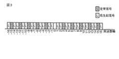
まず、信号−サブキャリア割当部103での第1の割り当て方式について説明する。図2〜図4は、第1の割り当て方式の基本例を示している。第1の割り当て方式では、基本的に±N*k番目の第1サブキャリアに割り当てられる第1信号として定常信号Sを用い、±N*k番目以外の第2サブキャリアに割り当てられる第2信号として低生起信号Lを用いる。ここで、定常信号とは定常的に生成される信号であり、±N*k番目の第1サブキャリアには常に何らかの電力値を有する信号が割り当てられている。低生起信号とは非定常信号、すなわち生起頻度の低い信号を指す。信号が生起されないときはサブキャリアにヌルが割り当てられている。(First allocation method)
First, the first allocation scheme in signal-
図2及び図4はN=2の例を示し、図3はN=3の例を示している。図2〜図4に示されるように、各サブキャリアは周波数軸上でOFDM帯域の中心周波数(0)の前後方向に、昇順に番号付けされている。OFDM帯域とは、OFDMシンボルを構成する全サブキャリアの周波数帯域をいう。OFDM帯域の中心周波数のサブキャリアは、実際には使用されないサブキャリアであるため、以下では特に考慮しない。一つのOFDMシンボル(同期用シンボル)内の有効なサブキャリア数は、図2及び図4では20個、図3では32個であるが、基地局がカバーするセル半径が数km程度のシステムでは、サブキャリア数が1000以上というような非常に大きい数になる場合もある。 2 and 4 show an example of N = 2, and FIG. 3 shows an example of N = 3. As shown in FIGS. 2 to 4, each subcarrier is numbered in ascending order in the front-rear direction of the center frequency (0) of the OFDM band on the frequency axis. The OFDM band refers to the frequency band of all subcarriers constituting the OFDM symbol. Since the subcarrier of the center frequency of the OFDM band is a subcarrier that is not actually used, no particular consideration is given below. The effective number of subcarriers in one OFDM symbol (synchronization symbol) is 20 in FIGS. 2 and 4 and 32 in FIG. 3, but in a system where the cell radius covered by the base station is about several kilometers. In some cases, the number of subcarriers may be as large as 1000 or more.
図2及び図3の例では、第1サブキャリアの全てに定常信号Sが割り当てられ、第2サブキャリアの全てに低生起信号Lが割り当てられている。図4の例では、第1サブキャリアの全てに定常信号Sが割り当てられ、第2サブキャリアの一部に低生起信号Lが割り当てられている。低生起信号Lとしては、例えばページング信号やランダムアクセス信号などが挙げられる。第2サブキャリアのうち、割り当てられる低生起信号Lが実際に生起していないサブキャリアには、ヌルが挿入される。低生起信号Lが割り当てられる第2サブキャリアの全て対して、割り当てられるべき信号が生起しなかった場合、第2サブキャリアの全てにヌルが割り当てられるため、生成される同期用シンボルは例えば非特許文献1に示された従来方式のOFDMトレーニングシンボルと同じになる。 In the example of FIGS. 2 and 3, the stationary signal S is assigned to all of the first subcarriers, and the low occurrence signal L is assigned to all of the second subcarriers. In the example of FIG. 4, the stationary signal S is assigned to all of the first subcarriers, and the low occurrence signal L is assigned to a part of the second subcarriers. Examples of the low occurrence signal L include a paging signal and a random access signal. Of the second subcarriers, nulls are inserted in subcarriers in which the assigned low occurrence signal L does not actually occur. For all of the second subcarriers to which the low occurrence signal L is assigned, if no signal to be assigned has occurred, nulls are assigned to all of the second subcarriers. This is the same as the conventional OFDM training symbol shown in
第2サブキャリアの全てに低生起信号Lが割り当てられる図2及び図3の例によると、OFDM帯域の中のどの部分帯域でみても、確率的に第1サブキャリアに割り当てられる信号の総電力よりも第2サブキャリアに割り当てられる信号の総電力の方が小さくなる。この結果、同期用シンボルの時間波形(同期用シンボルをIFFTにより時間領域の信号に変換した波形)は、繰り返し波形となる。すなわち、同期用シンボルの時間波形は受信側において受信する帯域によらず繰り返し波形となる。また図2及び図3の同期用シンボルは、第2サブキャリアの全てに低生起信号Lが割り当てられているため、第2サブキャリアの全てにヌルが割り当てられる従来方式と比べてサブキャリアの利用効率が向上する。 According to the example of FIGS. 2 and 3 in which the low occurrence signal L is allocated to all of the second subcarriers, the total power of the signals that are probabilistically allocated to the first subcarriers in any partial band in the OFDM band. The total power of the signal allocated to the second subcarrier is smaller than that. As a result, the time waveform of the synchronization symbol (the waveform obtained by converting the synchronization symbol into a time domain signal by IFFT) is a repetitive waveform. That is, the time waveform of the synchronization symbol is a repetitive waveform regardless of the band received on the receiving side. In addition, since the low-occurrence signal L is assigned to all of the second subcarriers in the synchronization symbols of FIG. 2 and FIG. Efficiency is improved.
一方、第2サブキャリアの一部に低生起信号Lが割り当てられる図4の例においては、図2の例と比べてサブキャリア利用効率は若干低下するものの、従来方式と比べて高いサブキャリア利用効率を有する。また、受信側においてフィルタにより周波数帯域を限定して受信することで、図2の例よりも精度の高い繰り返し波形を受信することができる。具体的には、例えば図4の第2サブキャリアのうち低生起信号Lが割り当てられていない−5番目のサブキャリアから5番目のサブキャリアまでの帯域を通過帯域とするフィルタを用いて受信信号の帯域制限を行うことにより、繰り返し波形を得ることができる。 On the other hand, in the example of FIG. 4 in which the low occurrence signal L is allocated to a part of the second subcarrier, the subcarrier utilization efficiency is slightly lower than that of the example of FIG. Have efficiency. Further, by receiving the frequency band limited by a filter on the receiving side, it is possible to receive a repetitive waveform with higher accuracy than the example of FIG. Specifically, for example, the low-occurrence signal L of the second subcarrier in FIG. 4 is not assigned to the received signal using a filter whose passband is a band from the fifth subcarrier to the fifth subcarrier. By performing this band limitation, a repetitive waveform can be obtained.
(受信機について)
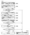
図5は、図1の送信側(送信機)に対応する受信側(受信機)の構成を示している。アンテナ201によって受信された信号は、無線部202によって増幅され、かつベースバンドアナログ信号に変換される。ベースバンドアナログ信号は、アナログ−ディジタル変換器(ADC)203によってベースバンドディジタル信号に変換される。ベースバンドディジタル信号は、フィルタ204、205及び206によってフィルタリング、すなわち帯域制限がなされる。(About the receiver)
FIG. 5 shows the configuration of the receiving side (receiver) corresponding to the transmitting side (transmitter) of FIG. A signal received by the
フィルタ206からの出力信号は、GI除去部210によりガードインターバルが除去された後、直並列変換器(S/P)211によりパラレル信号に変換される。直並列変換器211からの出力信号は、高速フーリエ変換器(FFT)212により周波数領域の信号に変換され、データ復調部213に入力される。データ復調部213により復調がなされることによって、OFDM信号により送信されたデータが再生される。 The output signal from the
一方、フィルタ205及び206からの出力信号は、以下に述べる同期処理ユニットに入力される。すなわち、フィルタ205からの出力信号はタイミング同期検出部208に入力される。タイミング同期検出部208は、同期用シンボルの信号、すなわち同期用シンボルの期間にフィルタ205から入力される信号を用いてシンボルタイミングを検出する。具体的には、タイミング同期検出部208は同期用シンボルの繰り返し波形間の相関値を求め、相関値のピーク位置を使ってシンボルタイミングを検出する。同期用シンボルに既知信号が含まれている場合には、既知信号を使ったマッチドフィルタの出力を使うことによってもシンボルタイミングを検出することができる。 On the other hand, output signals from the
タイミング同期検出部208により検出されたシンボルタイミングは、バッファ207及び周波数同期検出部209に与えられる。バッファ207では、タイミング同期の開始と共にデータのバッファリングを開始する。バッファ207には、フィルタ204からの出力信号が入力される。バッファ207は、フィルタ204からの入力信号の過去のある一定期間のデータをバッファリングする。一定期間とは、例えば同期用シンボル長でもよいし、処理遅延などの分の余裕を持たせて同期用シンボル長よりも少し長い時間であってもよい。 The symbol timing detected by the timing
タイミング同期検出部208により検出されたシンボルタイミングでバッファ207内のデータの更新が停止されると共に、バッファ207に蓄えられたデータから同期用シンボルが抜き出されて周波数同期検出部209に入力される。周波数同期検出部209は、バッファ207から入力された同期用シンボルを使ってキャリア周波数のオフセットの検出(周波数オフセット量の推定)を行う。具体的には、周波数同期検出部209は同期用シンボルの中から繰り返し波形を抜き出し、繰り返し波形間の相関をとることによりキャリア周波数のオフセット量を推定する。 Update of the data in the
さらに、タイミング同期検出部208により検出されたシンボルタイミング及び周波数同期検出部209により検出されたキャリア周波数のオフセットの情報は、図示していない各部に供給される。 Further, the symbol timing detected by the timing
次に、フィルタ204の通過帯域PB1及びフィルタ205の通過帯域PB2について説明する。周波数同期検出部209においては、入力信号として繰り返し波形が必要である。一方、タイミング同期検出部208においては、既知信号が挿入されている場合、必ずしも繰り返し波形を必要としない。 Next, the pass band PB1 of the
受信された同期用シンボルが図2に示した割り当て方式によって生成された同期用シンボルの場合、いずれの帯域においても繰り返し波形が得られる。従って、周波数同期検出部209の入力側に挿入されるフィルタ204の通過帯域PB1及びタイミング同期検出部208の入力側に挿入されるフィルタ205の通過帯域PB2は、共に図2中に示されるように同期用シンボルの信号全体にわたる帯域でよい。 When the received synchronization symbol is a synchronization symbol generated by the allocation method shown in FIG. 2, a repetitive waveform is obtained in any band. Accordingly, the pass band PB1 of the
これに対し、受信された同期用シンボルが図4に示した割り当て方式によって生成された同期用シンボルである場合、精度のよい繰り返し波形を生成するためには、同期用シンボルの信号の中心の帯域だけを切り出す必要がある。周波数同期検出部209においては繰り返し波形が必要であるため、フィルタ204の通過帯域PB1を図4中に示されるようにOFDM帯域の中心周波数付近に限定された帯域となるようにすればよい。受信された同期用シンボルが図4に示した割り当て方式によって生成された同期用シンボルであった場合においても、図2に示した場合と同程度の繰り返し波形の精度でよい場合には、図2に示す帯域を用いてもよい。 On the other hand, when the received synchronization symbol is a synchronization symbol generated by the allocation method shown in FIG. 4, in order to generate a precise repetitive waveform, the center band of the synchronization symbol signal is used. Only need to cut out. Since the frequency
フィルタ204及び205としては、例えば図4中に示したように通過帯域PB1及びPB2が同じである同一特性の場合には、一つのフィルタを共有してもよい。同期用シンボルの信号全体にわたる帯域をタイミング同期検出部208及び周波数同期検出部209に用いるような場合は、フィルタ204及び205を省略することもできる。電源制御部200は、無線部202及びディジタル部の一部の電源のオン/オフを制御するために設けられている。 As the
図6は、図1をより具体化した送信機を示している。図6に示されるように、定常信号生成器101は情報信号生成器111と既知信号生成器112によって構成される。図2〜図4における定常信号Sは、受信側にとって既知の情報であるかどうかによって2つに分けられる。すなわち、情報が既知の定常信号を既知信号と呼び、既知でない定常信号を情報信号と呼ぶ。情報信号は情報信号生成器111により生成され、既知信号は既知信号生成器112により生成される。 FIG. 6 shows a transmitter that more specifically embodies FIG. As shown in FIG. 6, the
(第1の割り当て方式の具体例)
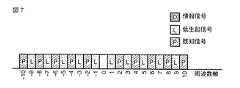
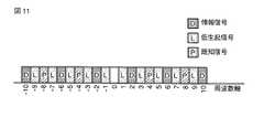
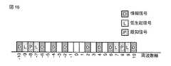
以下、第1の割り当て方式の具体例について説明する。図7〜図16は、N=2の場合の図2または図4における定常信号Sを既知信号Pと情報信号Dに区別した場合の同期用シンボルにおける信号−サブキャリア割り当ての例を示している。既知信号Pは図6の既知信号生成器112により生成され、情報信号Dは図6の情報信号生成器111により生成される。(Specific example of the first allocation method)
Hereinafter, a specific example of the first allocation method will be described. 7 to 16 show examples of signal-subcarrier allocation in a synchronization symbol when the steady signal S in FIG. 2 or FIG. 4 in the case of N = 2 is distinguished into a known signal P and an information signal D. . The known signal P is generated by the known
図7及び図8は、それぞれ図2及び図4を具体化した例であり、±N*k番目の第1サブキャリアに割り当てられる全ての定常信号を既知信号Pとしている。同様に、図9及び図10はそれぞれ図2及び図4を具体化した例であり、±N*k番目の第1サブキャリアに割り当てられる全ての定常信号を情報信号Dとしている。 FIGS. 7 and 8 are examples embodying FIGS. 2 and 4, respectively. All steady signals assigned to the ± N * k-th first subcarriers are known signals P. FIG. Similarly, FIGS. 9 and 10 are examples embodying FIGS. 2 and 4, respectively, and all stationary signals assigned to ± N * k-th first subcarriers are information signals D.
同様に、図11及び図12はそれぞれ図2及び図4を具体化した例であり、±N*k番目の第1サブキャリアに割り当てられる定常信号の一部を既知信号Pとし、他の一部を情報信号Dとしている。 Similarly, FIG. 11 and FIG. 12 are examples embodying FIG. 2 and FIG. 4, respectively. A part of the stationary signal allocated to the ± N * k-th first subcarrier is a known signal P, and the other one is shown. This portion is an information signal D.
図13〜図16は、図4を具体化した他の例を示している。図13においては、第1サブキャリアに割り当てられた定常信号のうち、低生起信号Lが割り当てられていない第2サブキャリアに近接する定常信号を情報信号Dとし、それ以外の定常信号を既知信号Pとしている。 13 to 16 show other examples embodying FIG. 4. In FIG. 13, among stationary signals assigned to the first subcarrier, a stationary signal close to the second subcarrier to which the low occurrence signal L is not assigned is defined as an information signal D, and other stationary signals are known signals. P.
図14においては、第1サブキャリアに割り当てられた定常信号のうち、低生起信号Lが割り当てられていない第2サブキャリアに近接するサブキャリアの定常信号を既知信号Pとし、それ以外の定常信号を情報信号Dとしている。 In FIG. 14, among the stationary signals assigned to the first subcarrier, the stationary signal of the subcarrier adjacent to the second subcarrier not assigned the low occurrence signal L is defined as the known signal P, and the other stationary signals. Is an information signal D.
図15においては、第1サブキャリアに割り当てられた定常信号のうち、低生起信号Lが割り当てられていない第2サブキャリアに近接する定常信号の一部を既知信号Pとし、それ以外の定常信号を情報信号Dとしている。 In FIG. 15, among the stationary signals assigned to the first subcarrier, a part of the stationary signal adjacent to the second subcarrier to which the low occurrence signal L is not assigned is set as the known signal P, and other stationary signals. Is an information signal D.
図16においては、第1サブキャリアに割り当てられた定常信号のうち、低生起信号Lが割り当てられていない第2サブキャリアに近接していない定常信号の一部を既知信号Pとし、それ以外の定常信号を情報信号Dとしている。 In FIG. 16, among the stationary signals assigned to the first subcarrier, a part of the stationary signal that is not close to the second subcarrier to which the low occurrence signal L is not assigned is set as the known signal P, and the other signals The stationary signal is the information signal D.
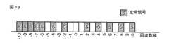
(第2の割り当て方式)
次に、信号−サブキャリア割当部103での第2の割り当て方式について説明する。図17〜図19は、第2の割り当て方式の基本例を示している。第2の割り当て方式では、基本的に±N*k番目の第1サブキャリアに割り当てられる第1信号及び±N*k番目以外の第2サブキャリアに割り当てられる第2信号として定常信号Lを用いる。但し、第2の割り当て方式では常に第2サブキャリアのうち一部にのみ定常信号Lが割り当てられる。(Second allocation method)
Next, the second allocation scheme in signal-
図17及び図18はそれぞれN=2及びN=4の例であり、第2サブキャリアのうちOFDM帯域の外側、すなわちサブキャリア番号のある一定値より絶対値が大きいサブキャリアのみに定常信号Sを割り当てている。図19はN=2のもう一つの例であり、第2サブキャリアのうち一部の連続した領域に定常信号Sを割り当てている。ここで「ある一定値」は例えば予めシステムで定められた値とする。他にも、システムが複数の帯域幅をサポートしている場合は、複数の帯域幅のうちの最大でないいずれかの帯域幅に対応するサブキャリア番号を一定値として用いてもよい。以下同様である。 FIGS. 17 and 18 are examples of N = 2 and N = 4, respectively. The stationary signal S is only applied to the second subcarrier outside the OFDM band, that is, only to subcarriers whose absolute value is larger than a certain value of the subcarrier number. Assigned. FIG. 19 shows another example in which N = 2, and the stationary signal S is assigned to a part of continuous regions of the second subcarrier. Here, the “certain fixed value” is, for example, a value determined in advance by the system. In addition, when the system supports a plurality of bandwidths, a subcarrier number corresponding to any non-maximum bandwidth among the plurality of bandwidths may be used as a constant value. The same applies hereinafter.
図17〜図19の例によると、OFDM帯域の部分帯域を、フィルタを用いて切り出すことで、第1サブキャリアに割り当てられる信号の総電力よりも第2サブキャリアに割り当てられる信号の総電力の方が小さくなり、結果として同期用シンボルの時間波形は繰り返し波形となる。例えば図17の例では、受信側において−5番目のサブキャリアから5番目のサブキャリアまでの帯域を通過帯域とするフィルタを用いて信号を帯域制限することにより、繰り返し波形を得ることができる。図19の例では、−5番目のサブキャリアよりも右側の帯域を通過帯域とするフィルタを用いて信号を帯域制限することにより、繰り返し波形を得ることができる。 According to the examples of FIGS. 17 to 19, the partial power of the signal allocated to the second subcarrier is more than the total power of the signal allocated to the first subcarrier by cutting out a partial band of the OFDM band using a filter. As a result, the time waveform of the synchronization symbol becomes a repetitive waveform. For example, in the example of FIG. 17, a repetitive waveform can be obtained by band limiting a signal using a filter whose pass band is a band from the −5th subcarrier to the 5th subcarrier on the receiving side. In the example of FIG. 19, a repetitive waveform can be obtained by band limiting a signal using a filter whose pass band is the band on the right side of the −5th subcarrier.
さらに、図17〜図19では第2サブキャリアの一部に低生起信号Lが割り当てられているため、第2サブキャリアの全てにヌルが割り当てられる従来方式と比べてサブキャリアの利用効率が向上する。 Further, in FIGS. 17 to 19, since the low occurrence signal L is allocated to a part of the second subcarrier, the utilization efficiency of the subcarrier is improved as compared with the conventional method in which nulls are allocated to all the second subcarriers. To do.
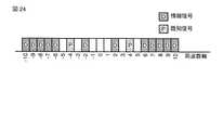
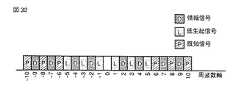
(第2の割り当て方式の具体例)
図20〜図24は、N=2の場合の図17または図19における定常信号Sを既知信号Pと情報信号Dに区別した場合の同期用シンボルにおける信号−サブキャリア割り当てを示している。既知信号Pは図6の既知信号生成器112により生成され、情報信号Dは図6の情報信号生成器111により生成される。(Specific example of the second allocation method)
20 to 24 show signal-subcarrier allocation in a synchronization symbol when the steady signal S in FIG. 17 or FIG. 19 in the case of N = 2 is distinguished from the known signal P and the information signal D. FIG. The known signal P is generated by the known
図20においては、第1サブキャリアに割り当てられる定常信号を既知信号Pとし、第2サブキャリアの一部に割り当てられる定常信号を情報信号Dとしている。 In FIG. 20, a stationary signal assigned to the first subcarrier is a known signal P, and a stationary signal assigned to a part of the second subcarrier is an information signal D.
図21においては、全ての定常信号、すなわち第1サブキャリアに割り当てられる定常信号及び第2サブキャリアの一部に割り当てられる定常信号を情報信号Dとしている。 In FIG. 21, all stationary signals, that is, stationary signals allocated to the first subcarrier and stationary signals allocated to a part of the second subcarrier are used as the information signal D.
図22においては、第1サブキャリアに割り当てられる定常信号のうちの一部を既知信号Pとし、それ以外の定常信号、すなわち第1サブキャリアに割り当てられる定常信号の他の一部と第2サブキャリアの一部に割り当てられる定常信号を情報信号Dとしている。 In FIG. 22, a part of the stationary signal assigned to the first subcarrier is a known signal P, and the other stationary signal, that is, the other part of the stationary signal assigned to the first subcarrier and the second subcarrier. The stationary signal assigned to a part of the carrier is the information signal D.
図23においては、第1サブキャリアに割り当てられる定常信号のうち特にOFDM帯域の内側の領域、すなわちサブキャリア番号の絶対値がある一定値より小さいサブキャリアの定常信号を既知信号Pとし、それ以外の定常信号、すなわち第1サブキャリアに割り当てられる定常信号の他の一部と第2サブキャリアの一部に割り当てられる定常信号を情報信号Dとしている。 In FIG. 23, among the stationary signals assigned to the first subcarrier, the region inside the OFDM band, that is, the stationary signal of the subcarrier whose absolute value of the subcarrier number is smaller than a certain value is set as the known signal P, and the others The stationary signal, that is, the stationary signal allocated to the other part of the stationary signal assigned to the first subcarrier and the stationary part of the second subcarrier is used as the information signal D.
図24においては、第1サブキャリアに割り当てられた定常信号のうちOFDM帯域の内側、すなわちサブキャリア番号の絶対値がある一定値より小さいサブキャリアの一部の定常信号を既知信号Pとし、それ以外の定常信号、すなわち第1サブキャリアに割り当てられる定常信号の他の一部と第2サブキャリアの一部に割り当てられる定常信号を情報信号Dとしている。 In FIG. 24, among the stationary signals assigned to the first subcarrier, the stationary signal that is part of the subcarrier inside the OFDM band, that is, the subcarrier number whose absolute value is smaller than a certain value is set as the known signal P. Other stationary signals, that is, stationary signals allocated to a part of the stationary signal allocated to the first subcarrier and a part of the second subcarrier are set as the information signal D.
(第3の割り当て方式)
次に、信号−サブキャリア割当部103での第3の割り当て方式について説明する。第3の割り当て方式では、±N*k(N:2以上の整数、k=1,2,...)番目の第1サブキャリアの全てに定常信号Sを割り当て、これ以外の第2サブキャリアの一部に定常信号Sを割り当て、さらに第2サブキャリアの残りの一部または全てに低生起信号Lを割り当てる。(Third allocation method)
Next, a third allocation scheme in signal-
図25及び図26は第3の割り当て方式の基本例であり、それぞれN=2及びN=3の場合の例である。図25及び図26の例では、第2サブキャリアのうちOFDM帯域の外側すなわちサブキャリア番号の絶対値がある一定値より大きいサブキャリアの一部に定常信号Sを割り当て、残りの内側すなわちサブキャリア番号の絶対値がある一定値より小さいサブキャリアに低生起信号Lを割り当てている。 FIGS. 25 and 26 are basic examples of the third allocation method, and are examples in the case of N = 2 and N = 3, respectively. In the example of FIGS. 25 and 26, the stationary signal S is assigned to a part of the second subcarrier outside the OFDM band, that is, a subcarrier having an absolute value of the subcarrier number larger than a certain value, and the remaining inside, that is, the subcarrier. The low occurrence signal L is assigned to subcarriers whose absolute number is smaller than a certain value.
図25及び図26の例によると、第1及び第2の割り当て方式と同様にOFDM帯域のうちのどの部分帯域でみても、確率的に第1サブキャリアに割り当てられる信号の総電力よりも第2サブキャリアに割り当てられる信号の総電力の方が小さくなり、結果として同期用シンボルの時間波形は繰り返し波形となる。さらに、図25及び図26の例では受信側において、OFDM帯域のうち低生起信号Lが割り当てられた内側の帯域を通過帯域とするフィルタを用いて信号を帯域制限することにより、全帯域を受信した場合よりも精度のよい繰り返し波形を得ることができる。 According to the examples of FIGS. 25 and 26, as in the first and second allocation schemes, any partial band of the OFDM band is more probabilistic than the total power of the signal allocated to the first subcarrier. The total power of the signal allocated to the two subcarriers becomes smaller, and as a result, the time waveform of the synchronization symbol becomes a repetitive waveform. Further, in the example of FIGS. 25 and 26, the receiving side receives the entire band by band-limiting the signal using a filter whose pass band is the inner band to which the low-occurrence signal L is allocated in the OFDM band. It is possible to obtain a repetitive waveform with higher accuracy than the case.
さらに、図25及び図26では第2サブキャリアの全てに定常信号Sまたは低生起信号Lが割り当てられているため、第2サブキャリアの全てにヌルが割り当てられる従来方式と比べてサブキャリアの利用効率が向上する。 Further, in FIG. 25 and FIG. 26, since the stationary signal S or the low occurrence signal L is assigned to all of the second subcarriers, the use of subcarriers compared to the conventional method in which nulls are assigned to all of the second subcarriers. Efficiency is improved.
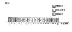
(第3の割り当て方式の具体例)
図27〜図32は、N=2の場合の図25における定常信号Sを既知信号Pと情報信号Dに区別した場合の同期用シンボルにおける信号−サブキャリア割り当てを示している。既知信号Pは図6の既知信号生成器112により生成され、情報信号Dは図6の情報信号生成器111により生成される。(Specific example of the third allocation method)
27 to 32 show signal-subcarrier allocation in a synchronization symbol when the stationary signal S in FIG. 25 in the case of N = 2 is distinguished into a known signal P and an information signal D. FIG. The known signal P is generated by the known
図27の例では、±N*k番目の第1サブキャリアに割り当てられた定常信号を既知信号Pとし、それ以外の第2サブキャリアに割り当てられた定常信号を情報信号Dとしている。 In the example of FIG. 27, the stationary signal assigned to the ± N * k-th first subcarrier is the known signal P, and the stationary signal assigned to the other second subcarriers is the information signal D.
図28においては、第1サブキャリア及び第2サブキャリアに割り当てられた全ての定常信号を情報信号Dとしている。 In FIG. 28, all stationary signals allocated to the first subcarrier and the second subcarrier are information signals D.
図29においては第1サブキャリアに割り当てられた定常信号の一部を既知信号Pとし、それ以外の定常信号、すなわち第1サブキャリアのうち既知信号Pが割り当てられていないサブキャリアに割り当てられた定常信号及び第2サブキャリアに割り当てられた定常信号を情報信号Dとしている。 In FIG. 29, a part of the stationary signal assigned to the first subcarrier is a known signal P, and other stationary signals, that is, the first subcarriers assigned to the subcarriers to which the known signal P is not assigned. The stationary signal and the stationary signal assigned to the second subcarrier are information signals D.
図30においては、第1サブキャリアに割り当てられた定常信号のうち、第2サブキャリアり割り当てられた低生起信号Lに近接する信号を既知信号Pとし、それ以外の定常信号を情報信号Dとしている。 In FIG. 30, among the stationary signals assigned to the first subcarrier, a signal close to the low occurrence signal L assigned to the second subcarrier is set as the known signal P, and other stationary signals are set as the information signal D. Yes.
図31においては、第1サブキャリアに割り当てられた定常信号のうち、第2サブキャリアに割り当てられた低生起信号Lに近接する信号の一部を既知信号Pとし、それ以外の信号を情報信号Dとしている。 In FIG. 31, among the stationary signals assigned to the first subcarrier, a part of the signal close to the low occurrence signal L assigned to the second subcarrier is a known signal P, and other signals are information signals. D.
図32においては、第1サブキャリアに割り当てられた定常信号のうち、第2サブキャリアに割り当てられた低生起信号Lに近接しない信号を既知信号Pとし、それ以外の信号を情報信号Dとしている。 In FIG. 32, among stationary signals assigned to the first subcarrier, a signal that is not close to the low occurrence signal L assigned to the second subcarrier is a known signal P, and the other signals are information signals D. .
図33は、本発明の一実施形態に係る送信機の変形例を示しており、図1の送信機に生起頻度制御部110が追加されている。図2〜図4、図7〜図16、図25〜図32に示した信号−サブキャリア割り当て例では、±N*k番目以外の第2サブキャリアの一部または全てに低生起信号Lを挿入している。 FIG. 33 shows a modification of the transmitter according to the embodiment of the present invention, and an occurrence
生起頻度制御部110は、このように第2サブキャリアの一部または全てに低生起信号Lが割り当てられた同期用シンボルにおいて、低生起信号生成器102によって生成される低生起信号Lの生起頻度をある閾値未満になるように制御する。すなわち、生起頻度制御部110から低生起信号の生起頻度の上限を与える閾値が低生起信号生成器102に与えられ、低生起信号生成器102では与えられた閾値より小さくなるように制御された生起頻度に従って低生起信号を生成する。 The occurrence
生起頻度制御部110によって与えられる閾値は、大きく分けて以下の2つの基準をもとに算出される。第1の基準としては、±N*k番目の第1サブキャリアのうち信号が割り当てられているサブキャリアの数と、±N*k番目以外の第2サブキャリアのうち信号が割り当てられているサブキャリアの数との比を用いる。例えば、図2の例では第1サブキャリアの数と第2サブキャリアの数が等しい、すなわち上記の比が1である。そこで、生起頻度制御部110では閾値を1として、低生起信号Lの生起頻度を1未満となるように制御する。一方、図3の例では第1サブキャリアの数が第2サブキャリアの数の約半分であり、上記の比は約0.5である。従って、生起頻度制御部110は閾値を約0.5として、低生起信号Lの生起頻度を約0.5未満となるように制御する。 The threshold value given by the occurrence
生起頻度制御部110によって与えられる閾値に関する第2の基準は、伝送路歪に対するマージンである。先に示した第1の基準は理論的な限界を表しているが、実際の無線通信環境では送信信号が伝送路において伝送路歪と呼ばれる様々な歪を受け、その歪の影響によって繰り返し波形がくずれてしまう場合がある。そのため、この歪み分を考えたマージンを持たせる必要がある。例えば、図2の例では伝送路歪がない状態では第1の基準に基づいて生起頻度を1未満にすればよいが、伝送路歪みがある場合を考慮してマージンを持たせ、生起頻度を0.3未満にするといったことが考えられる。このように生起頻度を制限することにより、伝送路歪がある状況においても受信側で繰り返し波形を正しく抽出することができる。 The second criterion regarding the threshold given by the occurrence
(低生起信号をページング信号とした場合の例)
次に、低生起信号Lがページング信号である場合について具体的に説明する。ページング信号は、セルラーシステムなどにおいて基地局が端末を呼び出す際などに用いられる信号である。ページング信号を検出した端末は、基地局から呼び出しがあったとみなして通信を開始する。(Example when the low occurrence signal is a paging signal)
Next, the case where the low occurrence signal L is a paging signal will be specifically described. The paging signal is a signal used when a base station calls a terminal in a cellular system or the like. The terminal that detects the paging signal starts communication by assuming that there is a call from the base station.
図2に示したような信号−サブキャリア割り当てを有する同期用シンボルの例では、奇数番目のサブキャリア(第2サブキャリア)を各ユーザに割り当て、各ユーザは割り当てられたサブキャリアを観測することでページング信号を検出する。例えば、奇数番目のサブキャリアをそれぞれ異なるユーザに割り当てた場合、図2の例では10人のユーザに対して呼び出しの制御を行うことができる。1ユーザ当たり2個以上のサブキャリアを割り当てることにより、ページング信号の検出精度を高めることもできる。例えば、1ユーザ当たり2個のサブキャリアを割り当てると、図2の例では5人のユーザに対して呼び出しの制御を行うことができる。 In the example of the synchronization symbol having signal-subcarrier allocation as shown in FIG. 2, an odd-numbered subcarrier (second subcarrier) is allocated to each user, and each user observes the allocated subcarrier. To detect the paging signal. For example, when odd-numbered subcarriers are assigned to different users, in the example of FIG. 2, calling control can be performed for 10 users. By allocating two or more subcarriers per user, it is possible to improve the detection accuracy of the paging signal. For example, if two subcarriers are allocated per user, the call control can be performed for five users in the example of FIG.
基地局に接続しているユーザをいくつかのグループに分けて、グループ毎に呼び出しを行うこともできる。この場合、グループ呼び出しを行うための信号は、ページング信号と区別するため、ページングインディケータ(PI)信号と呼ぶことにする。PI信号は、グループに属する少なくとも一人のユーザに呼び出しがあることを示す。PI信号の送信後、ページング信号を送信することによってユーザが呼び出される。すなわち、PI信号によって起動されたユーザは、PI信号に後続するページング信号を受信することにより、自分宛てに呼び出しがあったかを検出することができる。1グループのユーザ数を10人とし、1グループ毎に2個のサブキャリアを割り当てた場合、図2の例では50人のユーザに対して呼び出しを行うことができる。 Users connected to the base station can be divided into several groups and a call can be made for each group. In this case, a signal for performing a group call is referred to as a paging indicator (PI) signal in order to distinguish it from a paging signal. The PI signal indicates that there is a call to at least one user belonging to the group. After sending the PI signal, the user is called by sending a paging signal. That is, the user activated by the PI signal can detect whether a call has been made to the user by receiving a paging signal subsequent to the PI signal. When the number of users in one group is 10 and two subcarriers are assigned to each group, in the example of FIG. 2, a call can be made to 50 users.
受信側において受信信号からページング信号を検出するためには、同期用シンボルを用いてシンボルタイミングの同期と周波数の同期を行うことが必要となる。シンボルタイミング同期がとれていないと、ページング信号が含まれる同期用シンボルが受信信号のどこにあるのか分からないため、ページング信号を検出することができない。周波数同期がとれていないと、周波数方向に信号がシフトしてしまうため、近接する他のサブキャリアの信号を検出してしまう場合がある。シンボルタイミング同期と周波数同期がとれている信号にFFTを施すことにより、サブキャリア毎の信号を正確に分離することができる。サブキャリア毎に分離された信号から、ユーザに割り当てられたサブキャリアに挿入されているページング信号を検出することができる。ユーザは割り当てられたサブキャリアを観測して、信号電力が検出された場合には呼び出しがあったとみなし、信号電力が検出されなかった場合には呼び出しがなかったとみなす。 In order to detect a paging signal from a received signal on the receiving side, it is necessary to synchronize symbol timing and frequency using a synchronization symbol. If the symbol timing is not synchronized, the paging signal cannot be detected because it is unknown where the synchronization symbol including the paging signal is in the received signal. If the frequency synchronization is not achieved, the signal shifts in the frequency direction, so that a signal of another adjacent subcarrier may be detected. By applying FFT to a signal that is synchronized with symbol timing and frequency, the signal for each subcarrier can be accurately separated. The paging signal inserted in the subcarrier assigned to the user can be detected from the signal separated for each subcarrier. The user observes the assigned subcarriers, and if the signal power is detected, the user considers that there is a call, and if the signal power is not detected, the user considers that there is no call.
このようにページング信号を検出するためには、前処理としてシンボルタイミング同期と周波数同期が必要となる。一般のセルラーシステムでは、ユーザはページング信号を定期的に確認し、自分宛の呼び出しがあるかどうか確認する。また、確認の結果として自分宛の呼び出しがなかった場合には、次の確認のタイミングまで端末を休止状態に移行して消費電力を下げる。すなわち、ページング信号の確認に要する時間が短いほど、呼び出しの確認に要する消費電力を削減でき、結果として待ち受け時間を長くできる。 Thus, in order to detect a paging signal, symbol timing synchronization and frequency synchronization are required as preprocessing. In a general cellular system, a user periodically checks a paging signal and checks whether there is a call addressed to the user. If there is no call addressed to itself as a result of the confirmation, the terminal shifts to a dormant state until the next confirmation timing to reduce power consumption. That is, the shorter the time required for confirming the paging signal, the more the power consumption required for confirming the call can be reduced, and as a result, the standby time can be lengthened.
前述した同期用シンボルは、シンボルタイミング同期用の信号と周波数同期用の信号及びページング用の信号の全てを含むことができる。従って、一つの同期用シンボルを受信するだけでシンボルタイミング同期と周波数同期及びページング用の各信号の検出を確認することができるため、同期用の信号とページング用の信号を別々のOFDMシンボルに挿入する方法と比べて、ページング信号の検出に要する時間を削減することができるという利点が得られる。 The synchronization symbol described above can include all of the symbol timing synchronization signal, the frequency synchronization signal, and the paging signal. Therefore, detection of each signal for symbol timing synchronization, frequency synchronization, and paging can be confirmed by receiving only one synchronization symbol, so that the synchronization signal and the paging signal are inserted into separate OFDM symbols. Compared to the method, the advantage that the time required for detecting the paging signal can be reduced is obtained.
以下、低生起信号Lがページング信号である場合の受信機構成、同期用シンボルを含むフレーム構成及び受信シーケンスについて説明する。 Hereinafter, a receiver configuration, a frame configuration including a synchronization symbol, and a reception sequence when the low occurrence signal L is a paging signal will be described.
図34は、低生起信号Lがページング信号である場合の受信機の構成例であり、図5に示した受信機に対してフィルタ221、バッファ222、周波数オフセット補正部223及びページング信号検出部224が追加されている。 FIG. 34 is a configuration example of a receiver when the low occurrence signal L is a paging signal. The receiver 22 illustrated in FIG. 5 includes a
アンテナ201によって受信された信号は、無線部202によって増幅され、かつベースバンドアナログ信号に変換される。ベースバンドアナログ信号はアナログ−ディジタル変換器(ADC)203によってベースバンドディジタル信号に変換される。ベースバンドディジタル信号は、フィルタ204、205、206及び221によってフィルタリングされる。 A signal received by the
フィルタ206からの出力信号は、GI除去部210によりガードインターバルが除去された後、直並列変換器(S/P)211によりパラレル信号に変換される。直並列変換器211からの出力信号は高速フーリエ変換器(FFT)212により周波数領域の信号に変換され、データ復調部213により復調される。 The output signal from the
フィルタ205からの出力信号は、タイミング同期検出部208に入力される。タイミング同期検出部208は、同期用シンボルの期間にフィルタ205から入力される信号を用いてシンボルタイミングを検出する。具体的には、タイミング同期検出部208は同期用シンボルの繰り返し波形間の相関値を求め、相関値のピーク位置を使ってシンボルタイミングを検出する。同期用シンボルに挿入されている信号が既知信号であった場合には、既知信号を使ったマッチドフィルタの出力を使うことによってもシンボルタイミングを検出することができる。 An output signal from the
タイミング同期検出部208により検出されたシンボルタイミングは、バッファ207、周波数同期検出部209及びバッファ222に与えられる。バッファ207では、タイミング同期の開始と共にデータのバッファリングを開始する。バッファ207には、フィルタ204からの出力信号が入力される。バッファ207は、フィルタ204からの入力信号の過去のある一定期間のデータをバッファリングする。一定期間とは、例えば同期用シンボル長でもよいし、処理遅延などの分の余裕を持たせて同期用シンボル長よりも少し長い時間であってもよい。 The symbol timing detected by the timing
タイミング同期検出部208により検出されたシンボルタイミングでバッファ207内のデータの更新が停止されると共に、バッファ207に蓄えられたデータから同期用シンボルが抜き出されて周波数同期検出部209に入力される。周波数同期検出部209は、バッファ207から入力された同期用シンボルを使って周波数オフセットの検出(周波数オフセット量の推定)を行う。具体的には、周波数同期検出部209は同期用シンボルの中から繰り返し波形を抜き出し、繰り返し波形間の相関をとることによりキャリア周波数のオフセット量を推定する。こうして得られる周波数オフセット量の情報は、周波数オフセット補正部223に与えられる。 Update of the data in the
一方、バッファ222はタイミング同期の開始と共にデータのバッファリングを開始し、過去のある一定期間のデータを保持し続ける。バッファ222には、フィルタ221からの出力信号が入力される。タイミング同期検出部208により検出されたシンボルタイミングでバッファ222内のデータの更新が停止されると共に、バッファ222に蓄えられたデータから同期シンボルが抜き出されて、周波数オフセット補正部223に入力される。周波数オフセット補正部223では、周波数同期検出器209から与えられた周波数オフセット量の情報を用いて、バッファ222から入力された同期用シンボルの周波数オフセットの補正を行う。 On the other hand, the
周波数オフセットが補正された同期用シンボルは、ページング信号検出部224に入力される。ページング信号検出部224では、入力された同期用シンボルからページング信号を検出する。このようにしてシンボルタイミングの同期及び周波数の同期がとれた信号からページング信号を抜き出して検出し、呼び出しを検出することができる。 The synchronization symbol with the corrected frequency offset is input to the paging
図34中に示した4つのフィルタ204〜206及び221については、通過帯域が同じでよい場合には一つのフィルタを共有してもよい。帯域制限が必要でない場合には、これらのフィルタを省略してもよい。バッファ207及び222については、データを保持する期間が同じ場合には一つのバッファを共有することもできる。電源制御部200は、後述するように無線部202及びディジタル部の一部の電源のオン/オフを制御するために設けられている。 The four
(第1のフレーム構成及び受信シーケンス)
次に、図35及び図36を用いて低生起信号Lがページング信号である場合のフレーム構成及び受信シーケンスについて説明する。図35に示されるように、OFDM信号に低生起信号Lがページング信号である同期用シンボルが適宜挿入される。同期用シンボルの前後には、他のOFDMシンボルが挿入される。(First frame configuration and reception sequence)
Next, a frame configuration and a reception sequence when the low occurrence signal L is a paging signal will be described using FIG. 35 and FIG. As shown in FIG. 35, a synchronization symbol in which the low occurrence signal L is a paging signal is appropriately inserted into the OFDM signal. Other OFDM symbols are inserted before and after the synchronization symbol.
次に、図36を用いて受信シーケンスを説明すると、まず無線部202及びディジタル部の一部(例えば、図34中のADC203以降の要素)の電源を投入し、受信機が安定するまで待機する(ステップS101)。ステップS101の処理は、図35中の期間T11において行われる。一般の無線通信装置では、電源投入直後は動作が不安定であるため、ある程度の待機時間が必要となる。特に、キャリア周波数を決定するシンセサイザの出力周波数は、電源投入直後は振れている。このような不安定状態でシンボルタイミング同期及び周波数同期を行うと、シンボルタイミング同期の精度が低下し、また周波数同期の後でキャリア周波数が変わってしまう可能性がある。そのため、同期処理を開始するよりも前に、シンセサイザの出力周波数を安定化させる必要がある。 Next, the reception sequence will be described with reference to FIG. 36. First, the
次に、図35の一定期間T12にわたり同期位置の検出を行い、またこれと並行して過去の一定期間のデータをバッファ207及び222に保持する(ステップS102)。ここで一定期間T12は、あらかじめ分かっている情報から同期用シンボルが来ると予想される時間の前後を含むように設定される。ステップS103の結果、一定期間T12において同期位置(シンボルタイミング)が検出されなかった場合(ステップS103の結果がNOの場合)には、無線部202及びディジタル部の一部の電源を落として休止状態に移行する(ステップS110)。 Next, the synchronization position is detected over a certain period T12 in FIG. 35, and data in the past certain period is held in the
ステップS103でシンボルタイミングが検出された場合(ステップS103の結果がYESの場合)には、図35の期間T13においてステップS104〜S107の処理を行う。すなわち、ステップS103で検出された同期位置(シンボルタイミング)を基準として、バッファ207内のデータから同期用シンボルを抽出する(ステップS104)。抽出された同期用シンボルを使って、周波数オフセット量の検出(推定)を行う(ステップS105)。検出された周波数オフセット量を使用して同期用シンボルの周波数オフセットを補正し(ステップS106)、次にページング信号を検出する(ステップS107)。 When the symbol timing is detected in step S103 (when the result of step S103 is YES), the processes of steps S104 to S107 are performed in the period T13 of FIG. That is, a synchronization symbol is extracted from the data in the
ステップS107においてページング信号が検出されなかった場合(ステップS108の結果がNOの場合)には、無線部及びディジタル部の一部の電源を落として休止状態に移行する(ステップS110)。ページング信号が検出された場合(ステップS108の結果がYESの場合)には、図35の期間T14において無線通信を開始する(ステップS109)。なお、図37に示されるように同期用シンボルは定期的に挿入されてもよい。 If no paging signal is detected in step S107 (if the result of step S108 is NO), the wireless unit and the digital unit are partially powered down to enter a sleep state (step S110). When a paging signal is detected (when the result of step S108 is YES), wireless communication is started in period T14 of FIG. 35 (step S109). Note that the synchronization symbol may be periodically inserted as shown in FIG.
(第2のフレーム構成及び受信シーケンス)
次に、図38及び図39を用いて低生起信号LがPI信号である場合のフレーム構成及び受信シーケンスについて説明する。図38に示されるように、OFDM信号に低生起信号がPI信号である同期用シンボルが挿入される。前述したように、PI信号を使用した場合はPI信号に続いてページング信号が必要となるため、図38のように同期用シンボルの直後にページング信号を含むページング用シンボルを挿入している。(Second frame configuration and reception sequence)
Next, a frame configuration and a reception sequence when the low occurrence signal L is a PI signal will be described with reference to FIGS. 38 and 39. FIG. As shown in FIG. 38, a synchronization symbol whose low occurrence signal is a PI signal is inserted into the OFDM signal. As described above, when the PI signal is used, a paging signal is required after the PI signal. Therefore, as shown in FIG. 38, a paging symbol including a paging signal is inserted immediately after the synchronization symbol.
次に、図39の受信シーケンスを説明すると、図39のステップS201〜S206の処理は、図36のステップS101〜S106の処理と同様である。すなわち、まず無線部202及びディジタル部の一部の電源を投入し、受信機が安定するまで待機する(ステップS201)。ステップS201の処理は、図38中の期間T21において行われる。次に、図38の一定期間T22にわたり同期位置の検出を行い、またこれと並行して過去の一定期間のデータをバッファ207及び222に保持する(ステップS202)。ここで一定期間T22は、あらかじめ分かっている情報から同期用シンボルが来ると予想される時間の前後を含むように設定される。ステップS203の結果、一定期間T22において同期位置(シンボルタイミング)が検出されなかった場合(ステップS203の結果がNOの場合)には、無線部202及びディジタル部の一部の電源を落として休止状態に移行する(ステップS213)。 Next, the reception sequence in FIG. 39 will be described. The processing in steps S201 to S206 in FIG. 39 is the same as the processing in steps S101 to S106 in FIG. That is, first, the
ステップS203でシンボルタイミングが検出された場合(ステップS203の結果がYESの場合)には、図35の期間T23においてステップS204〜S207の処理を行う。すなわち、ステップS203で検出された同期位置(シンボルタイミング)を基準として、バッファ207内のデータから同期用シンボルを抽出する(ステップS204)。抽出された同期用シンボルを使って、周波数オフセット量の検出(推定)を行う(ステップS205)。検出された周波数オフセット量を使用して同期用シンボルの周波数オフセットを補正し(ステップS206)、次にPI信号を検出する(ステップS207)。ステップS207においてPI信号が検出されなかった場合(ステップS208の結果がNOの場合)には、無線部及びディジタル部の一部の電源を落として休止状態に移行する(ステップS213)。 When the symbol timing is detected in step S203 (when the result of step S203 is YES), the processes of steps S204 to S207 are performed in a period T23 of FIG. That is, a synchronization symbol is extracted from the data in the
ステップS207においてPI信号が検出された場合(ステップS208の結果がYESの場合)には、図38の期間T24においてステップS209及びS210の処理を行う。すなわち、ステップS205で推定された周波数オフセット量を使用してページング用シンボルの周波数オフセットを補正し(ステップS209)、次にページング信号を検出する(ステップS210)。 When the PI signal is detected in step S207 (when the result of step S208 is YES), the processes of steps S209 and S210 are performed in the period T24 of FIG. That is, the frequency offset of the paging symbol is corrected using the frequency offset amount estimated in step S205 (step S209), and then the paging signal is detected (step S210).
ステップS210においてページング信号が検出されなかった場合(ステップS211の結果がNOの場合)には、無線部及びディジタル部の一部の電源を落として休止状態に移行する(ステップS213)。ページング信号が検出された場合(ステップS211の結果がYESの場合)には、図38の期間T25において無線通信を開始する(ステップS212)。 If no paging signal is detected in step S210 (if the result of step S211 is NO), the wireless unit and the digital unit are partially powered down to enter a sleep state (step S213). When a paging signal is detected (when the result of step S211 is YES), wireless communication is started in a period T25 of FIG. 38 (step S212).
(第3のフレーム構成及び受信シーケンス)
次に、図40及び図41を用いて低生起信号LがPI信号である場合の他のフレーム構成及び受信シーケンスについて説明する。図40に示されるように、OFDM信号に低生起信号がPI信号である同期用シンボルが挿入される。図38の例では同期用シンボルの直後にページング信号を含むページング用シンボルが挿入されているが、図40の例では同期用シンボルとの間にブランク期間を空けてページング用シンボルが挿入されている。このブランク期間を利用して、シンセサイザの出力周波数の補正を行うことができる。(Third frame configuration and reception sequence)
Next, another frame configuration and reception sequence when the low occurrence signal L is a PI signal will be described with reference to FIGS. 40 and 41. As shown in FIG. 40, a synchronization symbol whose low occurrence signal is a PI signal is inserted into the OFDM signal. In the example of FIG. 38, a paging symbol including a paging signal is inserted immediately after the synchronization symbol, but in the example of FIG. 40, a paging symbol is inserted with a blank period between it and the synchronization symbol. . Using this blank period, the output frequency of the synthesizer can be corrected.
次に、図41の受信シーケンスを説明すると、図41のステップS301〜S306の処理は、図36のステップS101〜S106の処理及び図39のステップS201〜206とほぼ同様である。すなわち、まず無線部202及びディジタル部の一部の電源を投入し、受信機が安定するまで待機する(ステップS301)。ステップS301の処理は、図41中の期間T31において行われる。次に、図41の一定期間T32にわたり同期位置の検出を行い、またこれと並行して過去の一定期間のデータをバッファ207及び222に保持する(ステップS302)。ここで一定期間T32は、あらかじめ分かっている情報から同期用シンボルが来ると予想される時間の前後を含むように設定される。ステップS303の結果、一定期間T32において同期位置(シンボルタイミング)が検出されなかった場合(ステップS303の結果がNOの場合)には、無線部202及びディジタル部の一部の電源を落として休止状態に移行する(ステップS312)。 Next, the reception sequence in FIG. 41 will be described. The processing in steps S301 to S306 in FIG. 41 is substantially the same as the processing in steps S101 to S106 in FIG. 36 and steps S201 to 206 in FIG. That is, first, a part of power of the
ステップS303でシンボルタイミングが検出された場合(ステップS303の結果がYESの場合)には、図40の期間T33においてステップS304〜S307の処理を行う。すなわち、ステップS303で検出された同期位置(シンボルタイミング)を基準として、バッファ207内のデータから同期用シンボルを抽出する(ステップS304)。抽出された同期用シンボルを使って、周波数オフセット量の検出(推定)を行う(ステップS305)。検出された周波数オフセット量を使用して同期用シンボルの周波数オフセットを補正し(ステップS306)、次にPI信号の検出とキャリア周波数のオフセット補正を行う(ステップS307)。ステップS307においてPI信号が検出されなかった場合(ステップS308の結果がNOの場合)には、無線部及びディジタル部の一部の電源を落として休止状態に移行する(ステップS312)。 When the symbol timing is detected in step S303 (when the result of step S303 is YES), the processes of steps S304 to S307 are performed in the period T33 of FIG. That is, a synchronization symbol is extracted from the data in the
シンセサイザの出力周波数の補正においては、出力周波数が収束するまでに一定の期間がかかり、その間は受信信号を正確に受信することができない。そこで、図40に示される受信シーケンスでは、期間T33を経てシンセサイザの出力周波数が補正により安定化してからページング用シンボルが到来するようにしている。 In the correction of the output frequency of the synthesizer, it takes a certain period until the output frequency converges, and during that time, the received signal cannot be received accurately. Therefore, in the reception sequence shown in FIG. 40, the paging symbol arrives after the output frequency of the synthesizer is stabilized by the correction after the period T33.
ステップS307においてPI信号が検出された場合(ステップS308の結果がYESの場合)には、図40の期間T34においてページング用シンボルからページング信号を検出する(ステップS309)。図39に示した受信シーケンスでは、ステップS206において周波数オフセットの補正が必要であったが、図40の受信シーケンスではステップS307においてキャリア周波数(シンセサイザの出力周波数)を補正しているため、周波数オフセットの補正をしなくてもよい。 When the PI signal is detected in step S307 (when the result of step S308 is YES), the paging signal is detected from the paging symbol in period T34 of FIG. 40 (step S309). In the reception sequence shown in FIG. 39, the frequency offset needs to be corrected in step S206. However, in the reception sequence in FIG. 40, the carrier frequency (the output frequency of the synthesizer) is corrected in step S307. There is no need to make corrections.
ステップS309においてページング信号が検出された場合(ステップS310の結果がYESの場合)には、図40の期間T35において無線通信を開始する(ステップS311)。 If a paging signal is detected in step S309 (if the result of step S310 is YES), wireless communication is started in period T35 of FIG. 40 (step S311).
なお、本発明は上記実施形態そのままに限定されるものではなく、実施段階ではその要旨を逸脱しない範囲で構成要素を変形して具体化できる。また、上記実施形態に開示されている複数の構成要素の適宜な組み合わせにより、種々の発明を形成できる。例えば、実施形態に示される全構成要素から幾つかの構成要素を削除してもよい。さらに、異なる実施形態にわたる構成要素を適宜組み合わせてもよい。 Note that the present invention is not limited to the above-described embodiment as it is, and can be embodied by modifying the constituent elements without departing from the scope of the invention in the implementation stage. In addition, various inventions can be formed by appropriately combining a plurality of constituent elements disclosed in the embodiment. For example, some components may be deleted from all the components shown in the embodiment. Furthermore, constituent elements over different embodiments may be appropriately combined.
101・・・定常信号生成器;
102・・・低生起信号生成器;
103・・・信号−サブキャリア割当部;
104・・・逆高速フーリエ変換器;
105・・・並直列変換器;
106・・・ガードインターバル付加部;
107・・・ディジタル−アナログ変換器;
108・・・無線部;
109・・・アンテナ;
110・・・生起頻度制御部;
111・・・情報信号生成器;
112・・・既知信号生成器;
200・・・電源制御部;
201・・・アンテナ;
202・・・無線部;
203・・・アナログ−ディジタル変換器;
204〜206・・・フィルタ;
207・・・バッファ;
208・・・タイミング同期検出部;
209・・・周波数同期検出部;
210・・・ガードインターバル除去部;
211・・・直並列変換器;
212・・・高速フーリエ変換器;
213・・・データ復調部;
221・・・フィルタ;
222・・・バッファ;
223・・・周波数オフセット補正部;
224・・・ページング信号検出部;101 ... Stationary signal generator;
102 ... low occurrence signal generator;
103 Signal-subcarrier allocation unit;
104 ... Inverse Fast Fourier Transformer;
105 ... parallel-to-serial converter;
106 ... guard interval addition part;
107 ... Digital-to-analog converter;
108 ... radio part;
109 ... antenna;
110... Occurrence frequency control unit;
111 ... information signal generator;
112 ... known signal generator;
200: power control unit;
201 ... antenna;
202 ... wireless unit;
203 ... analog-digital converter;
204-206 ... filter;
207 ... buffer;
208... Timing synchronization detector;
209 ... Frequency synchronization detector;
210 ... guard interval removal unit;
211 ... Series-parallel converter;
212 ... fast Fourier transform;
213 ... Data demodulation unit;
221 ... Filter;
222... Buffer;
223 ... Frequency offset correction unit;
224 ... Paging signal detection unit;
Claims (10)
Translated fromJapanese前記同期用シンボルの±N*k(N:2以上の整数、k=1,2,...)番目の第1サブキャリアに定常的に生成される第1信号を割り当て、前記同期用シンボルのうちの中心のサブキャリアを除く他の第2サブキャリアの一部に、前記第1信号の総電力よりも小さい総電力をもつ第2信号を前記サブキャリア番号の絶対値がある一定値より大きいサブキャリアに優先的に割り当てる割当部を具備する無線通信装置。In a radio communication apparatus that transmits signals of frequency division multiplexing (OFDM) symbols including synchronization symbols, each havinga plurality of subcarriers that are orthogonal to each otherand numbered in ascending order in the front-rear direction of the center frequency ,
A first signal that is regularly generated is assigned to the first subcarrier of ± N * k (N: integer greater than or equal to 2, k = 1, 2,...) Of the synchronization symbol, and the synchronization symbol The second signal having a total power smaller than the total power of the first signal is included in apart of the second subcarriers other than the central subcarrier of the firstsubcarrier number from a certain constant value. A wireless communication apparatus comprising an assigning unit thatpreferentially assignslarge subcarriers .
(a)前記同期用シンボルの±N*k(N:2以上の整数、k=1,2,...)番目の第1サブキャリアに定常的に生成される第1信号を割り当て、(b)前記同期用シンボルのうちの中心のサブキャリアを除く他の第2サブキャリアの少なくとも一部に、前記第1信号の総電力よりも小さい総電力をもつ第2信号として非定常的に生成される信号を前記サブキャリア番号の絶対値がある一定値より小さいサブキャリアに優先的に割り当て、前記第2信号として定常的に生成される信号を前記サブキャリア番号の絶対値が前記一定値より大きいサブキャリアに優先的に割り当てる割当部を具備する無線通信装置。In a radio communication apparatus that transmits signals of frequency division multiplexing (OFDM) symbols including synchronization symbols, each havinga plurality of subcarriers that are orthogonal to each otherand numbered in ascending order in the front-rear direction of the center frequency ,
(A) the ± a synchronizing symbol N * k (N: 2 or more integer, k = 1, 2, ...) th first signal constantly produced in the first subcarrierallocation, ( b)Generated non-stationarily as a second signal having a total power smaller than the total power of the first signal in at least a part of the second subcarriers other than the central subcarrier of the synchronization symbol.Is assigned preferentially to subcarriers whose absolute value of the subcarrier number is smaller than a certain value, and a signal that is steadily generated as the second signal is an absolute value of the subcarrier number from the certain value. A wireless communication apparatus comprising an assigning unit thatpreferentially assignslarge subcarriers .
前記同期用シンボルの±N*k(N:2以上の整数、k=1,2,...)番目の第1サブキャリアに定常的に生成される第1信号を割り当て、前記同期用シンボルのうちの中心のサブキャリアを除く他の第2サブキャリアの一部に、前記第1信号の総電力よりも小さい総電力をもつ第2信号を前記サブキャリア番号の絶対値がある一定値より大きいサブキャリアに優先的に割り当てることを特徴とする同期用シンボルにおける信号−サブキャリア割り当て方法。A method of assigning a signal to each subcarrier of a synchronization symbol for frequency division multiplexing (OFDM) havinga plurality of subcarriers orthogonal to each otherand numbered in ascending order in the front-back direction of the center frequency ,
A first signal that isregularly generated is assigned to the first subcarrier of ± N * k (N: integer greater than orequal to 2, k = 1, 2,...) Of the synchronization symbol, and the synchronization symbol The second signal having a total power smaller than the total power of the first signal is included in apart of the second subcarriers other than the central subcarrier of the firstsubcarrier number from a certain constant value. A signal-subcarrier allocation method in a synchronization symbol, characterizedby preferentially allocatingto a large subcarrier .
(a)前記同期用シンボルの±N*k(N:2以上の整数、k=1,2,...)番目の第1サブキャリアに定常的に生成される第1信号を割り当て、(b)前記同期用シンボルのうちの中心のサブキャリアを除く他の第2サブキャリアの少なくとも一部に、前記第1信号の総電力よりも小さい総電力をもつ第2信号として非定常的に生成される信号を前記サブキャリア番号の絶対値がある一定値より小さいサブキャリアに優先的に割り当て、前記第2信号として定常的に生成される信号を前記サブキャリア番号の絶対値がある一定値より大きいサブキャリアに優先的に割り当てることを特徴とする同期用シンボルにおける信号−サブキャリア割り当て方法。A method of assigning a signal to each subcarrier of a synchronization symbol for frequency division multiplexing (OFDM) havinga plurality of subcarriers orthogonal to each otherand numbered in ascending order in the front-back direction of the center frequency ,
(A) the ± a synchronizing symbol N * k (N: 2 or more integer, k = 1, 2, ...) th firstsignal constantly produced in the first subcarrierallocation, ( b)Generated non-stationarily as a second signal having a total power smaller than the total power of the first signal in at least a part of the second subcarriers other than the central subcarrier of the synchronization symbol.Is assigned preferentially to subcarriers whose absolute value of the subcarrier number is smaller than a certain fixed value, and a signal that is constantly generated as the second signal is assigned a certain absolute value from the certain value of the absolute value of the subcarrier number. A signal-subcarrier allocation method in a synchronization symbol, characterizedby preferentially allocatingto a large subcarrier .
受信されたOFDMシンボルの信号に含まれる前記同期用シンボルの信号を用いて前記無線通信装置との間の同期処理を行う同期処理ユニットとを具備する無線通信装置。A receiver that receives an OFDM symbol signal transmitted from the wireless communication apparatus according toclaim 1 or 4 ,
A wireless communication apparatus comprising: a synchronization processing unit that performs synchronization processing with the wireless communication apparatus using the synchronization symbol signal included in the received OFDM symbol signal.
Priority Applications (5)
| Application Number | Priority Date | Filing Date | Title |
|---|---|---|---|
| JP2005317681AJP4533833B2 (en) | 2005-10-31 | 2005-10-31 | Wireless communication apparatus and signal-subcarrier allocation method in synchronization symbol |
| EP06782835AEP1964347A1 (en) | 2005-10-31 | 2006-08-14 | Wireless transmitter, signal to subcarrier allocation method for synchronizing symbol, and wireless receiver |
| PCT/JP2006/316277WO2007052399A1 (en) | 2005-10-31 | 2006-08-14 | Wireless transmitter, signal to subcarrier allocation method for synchronizing symbol, and wireless receiver |
| CNA2006800013560ACN101080909A (en) | 2005-10-31 | 2006-08-14 | Wireless transmitter, method for signal-to-subcarrier allocation of synchronization symbols, and wireless receiver |
| US11/548,560US20070098096A1 (en) | 2005-10-31 | 2006-10-11 | Wireless transmitter, signal to subcarrier allocation method for synchronizing symbol, and wireless receiver |
Applications Claiming Priority (1)
| Application Number | Priority Date | Filing Date | Title |
|---|---|---|---|
| JP2005317681AJP4533833B2 (en) | 2005-10-31 | 2005-10-31 | Wireless communication apparatus and signal-subcarrier allocation method in synchronization symbol |
Publications (2)
| Publication Number | Publication Date |
|---|---|
| JP2007124593A JP2007124593A (en) | 2007-05-17 |
| JP4533833B2true JP4533833B2 (en) | 2010-09-01 |
Family
ID=37440844
Family Applications (1)
| Application Number | Title | Priority Date | Filing Date |
|---|---|---|---|
| JP2005317681AExpired - Fee RelatedJP4533833B2 (en) | 2005-10-31 | 2005-10-31 | Wireless communication apparatus and signal-subcarrier allocation method in synchronization symbol |
Country Status (5)
| Country | Link |
|---|---|
| US (1) | US20070098096A1 (en) |
| EP (1) | EP1964347A1 (en) |
| JP (1) | JP4533833B2 (en) |
| CN (1) | CN101080909A (en) |
| WO (1) | WO2007052399A1 (en) |
Families Citing this family (11)
| Publication number | Priority date | Publication date | Assignee | Title |
|---|---|---|---|---|
| EP1837875A1 (en)* | 2006-03-22 | 2007-09-26 | Deutsche Thomson-Brandt Gmbh | Method and apparatus for correlating two data sections |
| RU2476992C2 (en) | 2007-06-19 | 2013-02-27 | Панасоник Корпорэйшн | Wireless communication apparatus and response signal spreading method |
| US8743855B2 (en)* | 2007-12-17 | 2014-06-03 | Lg Electronics Inc. | Method of generating data and transmitting synchronization channel in mobile communication system |
| CN101946547B (en)* | 2007-12-18 | 2014-11-12 | 爱立信电话股份有限公司 | Quick Paging in Telecommunication System |
| CN102017745B (en)* | 2008-03-06 | 2015-07-22 | 爱立信电话股份有限公司 | Quick paging receivers in OFDMA telecommunication systems |
| US8259827B2 (en)* | 2009-01-16 | 2012-09-04 | Telefonaktiebolaget L M Ericsson (Publ) | Quick paging receivers in telecommunication systems |
| US8233428B2 (en)* | 2008-08-13 | 2012-07-31 | Telefonaktiebolaget Lm Ericsson (Publ) | Using a synchronization channel to send quick paging signals |
| US8483330B2 (en)* | 2009-09-01 | 2013-07-09 | Wi-Lan Inc. | Methods and apparatus for OFDM symbol synchronization for in-door digital TV reception |
| IT1397989B1 (en)* | 2010-02-11 | 2013-02-04 | Selex Communications Spa | INTEGRATION OF NARROWBAND RADIO CHANNELS AND BROADBAND RADIO CHANNELS IN A PROFESSIONAL RADIO COMMUNICATION SYSTEM. |
| JP5459669B2 (en)* | 2010-03-16 | 2014-04-02 | 株式会社東芝 | Magnetic resonance imaging system |
| CN106788958B (en)* | 2015-11-20 | 2019-12-17 | 北京信威通信技术股份有限公司 | Signal synchronization method and system |
Family Cites Families (14)
| Publication number | Priority date | Publication date | Assignee | Title |
|---|---|---|---|---|
| EP0938193A1 (en)* | 1998-02-18 | 1999-08-25 | Sony International (Europe) GmbH | Header structure for TDD systems |
| EP1073241A3 (en)* | 1999-07-29 | 2006-05-03 | Matsushita Electric Industrial Co., Ltd. | Symbol synchronisation in multicarrier transmission |
| JP4284769B2 (en)* | 1999-08-11 | 2009-06-24 | ソニー株式会社 | Multi-carrier signal transmitter and multi-carrier signal receiver |
| JP4288777B2 (en)* | 1999-08-11 | 2009-07-01 | ソニー株式会社 | Multi-carrier signal transmitter and multi-carrier signal receiver |
| EP1087585B1 (en)* | 1999-09-17 | 2013-08-21 | Alcatel-Lucent | Identification of a terrestrial repeater using inactive subcarriers of a multicarrier signal |
| JP3485860B2 (en)* | 2000-03-27 | 2004-01-13 | 松下電器産業株式会社 | Base station apparatus and wireless communication method |
| JP3462468B2 (en)* | 2000-11-27 | 2003-11-05 | 松下電器産業株式会社 | OFDM receiver, OFDM transmitter, and OFDM communication method |
| US7548506B2 (en)* | 2001-10-17 | 2009-06-16 | Nortel Networks Limited | System access and synchronization methods for MIMO OFDM communications systems and physical layer packet and preamble design |
| JP3693025B2 (en)* | 2002-02-21 | 2005-09-07 | ソニー株式会社 | Wireless communication method, wireless communication system, wireless base station, wireless communication terminal, program, and medium |
| JP3940414B2 (en)* | 2002-08-28 | 2007-07-04 | 富士通株式会社 | Reception apparatus and frame timing detection method thereof |
| KR100479864B1 (en)* | 2002-11-26 | 2005-03-31 | 학교법인 중앙대학교 | Method and apparatus embodying and synchronizing downlink signal in mobile communication system and method for searching cell using the same |
| JP4279027B2 (en)* | 2003-03-31 | 2009-06-17 | 株式会社ルネサステクノロジ | OFDM demodulation method and semiconductor integrated circuit |
| US7356322B2 (en)* | 2004-05-17 | 2008-04-08 | Agere Systems Inc. | Multiple-branch wireless receiver |
| US8488688B2 (en)* | 2004-10-29 | 2013-07-16 | Sharp Kabushiki Kaisha | Communication method and radio transmitter |
- 2005
- 2005-10-31JPJP2005317681Apatent/JP4533833B2/ennot_activeExpired - Fee Related
- 2006
- 2006-08-14WOPCT/JP2006/316277patent/WO2007052399A1/enactiveApplication Filing
- 2006-08-14CNCNA2006800013560Apatent/CN101080909A/enactivePending
- 2006-08-14EPEP06782835Apatent/EP1964347A1/ennot_activeWithdrawn
- 2006-10-11USUS11/548,560patent/US20070098096A1/ennot_activeAbandoned
Also Published As
| Publication number | Publication date |
|---|---|
| JP2007124593A (en) | 2007-05-17 |
| US20070098096A1 (en) | 2007-05-03 |
| EP1964347A1 (en) | 2008-09-03 |
| CN101080909A (en) | 2007-11-28 |
| WO2007052399A1 (en) | 2007-05-10 |
Similar Documents
| Publication | Publication Date | Title |
|---|---|---|
| EP1964347A1 (en) | Wireless transmitter, signal to subcarrier allocation method for synchronizing symbol, and wireless receiver | |
| JP5455893B2 (en) | Base station, mobile terminal and method for WiMAX system | |
| JP4367422B2 (en) | Wireless communication apparatus and wireless communication method | |
| CN103281284B (en) | For adjusting the method and the travelling carriage thereof that send timing and send grouping continuously | |
| JP5376333B2 (en) | Wireless communication system | |
| JP2001358695A (en) | Pilot use of spread-spectrum multiple access system based upon orthogonal frequency-division multiplexing | |
| CN108282317A (en) | Transmission method, reception method, base station and user equipment of synchronization signal block | |
| JPH1141197A (en) | Communication method and transmission device and receiving device and cellular radio communication system | |
| JP2008277973A (en) | Mobile communication system, base station apparatus and control method thereof | |
| JP4943749B2 (en) | Wireless device and communication system using the same | |
| WO2010018817A1 (en) | Base station, mobile station, signal transmission method, and signal reception method | |
| JPH1022973A (en) | OFDM transmission system and its transmission / reception device | |
| JP4841330B2 (en) | Radio apparatus and communication system | |
| JP4112397B2 (en) | Multi-carrier wireless communication system and multi-carrier modulation circuit | |
| CN110537386B (en) | Method, device, equipment and medium for transmitting and receiving synchronous broadcast block | |
| US20170230975A1 (en) | Wireless communication system, base station apparatus, and terminal apparatus | |
| KR20070039760A (en) | Downlink initial synchronization and cell search apparatus and method for base station apparatus and user terminal transmitting downlink signal in orthogonal frequency division multiple access mobile communication system | |
| CN101686082A (en) | Downlink synchronizing method and terminal | |
| JP2008187682A (en) | Wireless communication system | |
| JP2009027530A (en) | Band control method and controller utilizing the same | |
| EP1838030A3 (en) | Uplink signal receiving method and apparatus using successive interference cancellation in wireless transmission system based on OFDMA | |
| CN101426272B (en) | Pilot resource distribution method, system and equipment | |
| JP5284891B2 (en) | Communication apparatus and delay amount detection method | |
| JP2008085912A (en) | COMMUNICATION CONTROL METHOD FOR TDD / OFDMA COMMUNICATION SYSTEM, BASE STATION DEVICE, TERMINAL DEVICE, AND COMMUNICATION CONTROL SYSTEM | |
| JP2001333341A (en) | Digital broadcast receiver |
Legal Events
| Date | Code | Title | Description |
|---|---|---|---|
| A977 | Report on retrieval | Free format text:JAPANESE INTERMEDIATE CODE: A971007 Effective date:20091020 | |
| A131 | Notification of reasons for refusal | Free format text:JAPANESE INTERMEDIATE CODE: A131 Effective date:20091104 | |
| A521 | Request for written amendment filed | Free format text:JAPANESE INTERMEDIATE CODE: A523 Effective date:20091225 | |
| TRDD | Decision of grant or rejection written | ||
| A01 | Written decision to grant a patent or to grant a registration (utility model) | Free format text:JAPANESE INTERMEDIATE CODE: A01 Effective date:20100518 | |
| A01 | Written decision to grant a patent or to grant a registration (utility model) | Free format text:JAPANESE INTERMEDIATE CODE: A01 | |
| A61 | First payment of annual fees (during grant procedure) | Free format text:JAPANESE INTERMEDIATE CODE: A61 Effective date:20100614 | |
| FPAY | Renewal fee payment (event date is renewal date of database) | Free format text:PAYMENT UNTIL: 20130618 Year of fee payment:3 | |
| LAPS | Cancellation because of no payment of annual fees |