JP4533695B2 - Treatment endoscope - Google Patents
Treatment endoscopeDownload PDFInfo
- Publication number
- JP4533695B2 JP4533695B2JP2004224504AJP2004224504AJP4533695B2JP 4533695 B2JP4533695 B2JP 4533695B2JP 2004224504 AJP2004224504 AJP 2004224504AJP 2004224504 AJP2004224504 AJP 2004224504AJP 4533695 B2JP4533695 B2JP 4533695B2
- Authority
- JP
- Japan
- Prior art keywords
- unit
- observation
- distal end
- endoscope
- treatment
- Prior art date
- Legal status (The legal status is an assumption and is not a legal conclusion. Google has not performed a legal analysis and makes no representation as to the accuracy of the status listed.)
- Expired - Fee Related
Links
Images


Classifications
- A—HUMAN NECESSITIES
- A61—MEDICAL OR VETERINARY SCIENCE; HYGIENE
- A61B—DIAGNOSIS; SURGERY; IDENTIFICATION
- A61B1/00—Instruments for performing medical examinations of the interior of cavities or tubes of the body by visual or photographical inspection, e.g. endoscopes; Illuminating arrangements therefor
- A61B1/012—Instruments for performing medical examinations of the interior of cavities or tubes of the body by visual or photographical inspection, e.g. endoscopes; Illuminating arrangements therefor characterised by internal passages or accessories therefor
- A61B1/018—Instruments for performing medical examinations of the interior of cavities or tubes of the body by visual or photographical inspection, e.g. endoscopes; Illuminating arrangements therefor characterised by internal passages or accessories therefor for receiving instruments
- A—HUMAN NECESSITIES
- A61—MEDICAL OR VETERINARY SCIENCE; HYGIENE
- A61B—DIAGNOSIS; SURGERY; IDENTIFICATION
- A61B1/00—Instruments for performing medical examinations of the interior of cavities or tubes of the body by visual or photographical inspection, e.g. endoscopes; Illuminating arrangements therefor
- A61B1/00002—Operational features of endoscopes
- A61B1/00043—Operational features of endoscopes provided with output arrangements
- A61B1/00045—Display arrangement
- A61B1/0005—Display arrangement combining images e.g. side-by-side, superimposed or tiled
- A—HUMAN NECESSITIES
- A61—MEDICAL OR VETERINARY SCIENCE; HYGIENE
- A61B—DIAGNOSIS; SURGERY; IDENTIFICATION
- A61B1/00—Instruments for performing medical examinations of the interior of cavities or tubes of the body by visual or photographical inspection, e.g. endoscopes; Illuminating arrangements therefor
- A61B1/00064—Constructional details of the endoscope body
- A61B1/00071—Insertion part of the endoscope body
- A61B1/0008—Insertion part of the endoscope body characterised by distal tip features
- A61B1/00087—Tools
- A—HUMAN NECESSITIES
- A61—MEDICAL OR VETERINARY SCIENCE; HYGIENE
- A61B—DIAGNOSIS; SURGERY; IDENTIFICATION
- A61B1/00—Instruments for performing medical examinations of the interior of cavities or tubes of the body by visual or photographical inspection, e.g. endoscopes; Illuminating arrangements therefor
- A61B1/00064—Constructional details of the endoscope body
- A61B1/00071—Insertion part of the endoscope body
- A61B1/0008—Insertion part of the endoscope body characterised by distal tip features
- A61B1/00089—Hoods
- A—HUMAN NECESSITIES
- A61—MEDICAL OR VETERINARY SCIENCE; HYGIENE
- A61B—DIAGNOSIS; SURGERY; IDENTIFICATION
- A61B1/00—Instruments for performing medical examinations of the interior of cavities or tubes of the body by visual or photographical inspection, e.g. endoscopes; Illuminating arrangements therefor
- A61B1/00131—Accessories for endoscopes
- A61B1/00135—Oversleeves mounted on the endoscope prior to insertion
- A—HUMAN NECESSITIES
- A61—MEDICAL OR VETERINARY SCIENCE; HYGIENE
- A61B—DIAGNOSIS; SURGERY; IDENTIFICATION
- A61B1/00—Instruments for performing medical examinations of the interior of cavities or tubes of the body by visual or photographical inspection, e.g. endoscopes; Illuminating arrangements therefor
- A61B1/04—Instruments for performing medical examinations of the interior of cavities or tubes of the body by visual or photographical inspection, e.g. endoscopes; Illuminating arrangements therefor combined with photographic or television appliances
- A61B1/042—Instruments for performing medical examinations of the interior of cavities or tubes of the body by visual or photographical inspection, e.g. endoscopes; Illuminating arrangements therefor combined with photographic or television appliances characterised by a proximal camera, e.g. a CCD camera
- A—HUMAN NECESSITIES
- A61—MEDICAL OR VETERINARY SCIENCE; HYGIENE
- A61B—DIAGNOSIS; SURGERY; IDENTIFICATION
- A61B17/00—Surgical instruments, devices or methods
- A61B17/04—Surgical instruments, devices or methods for suturing wounds; Holders or packages for needles or suture materials
- A61B17/0469—Suturing instruments for use in minimally invasive surgery, e.g. endoscopic surgery
- A—HUMAN NECESSITIES
- A61—MEDICAL OR VETERINARY SCIENCE; HYGIENE
- A61B—DIAGNOSIS; SURGERY; IDENTIFICATION
- A61B17/00—Surgical instruments, devices or methods
- A61B17/04—Surgical instruments, devices or methods for suturing wounds; Holders or packages for needles or suture materials
- A61B17/0482—Needle or suture guides
- A—HUMAN NECESSITIES
- A61—MEDICAL OR VETERINARY SCIENCE; HYGIENE
- A61B—DIAGNOSIS; SURGERY; IDENTIFICATION
- A61B17/00—Surgical instruments, devices or methods
- A61B17/068—Surgical staplers, e.g. containing multiple staples or clamps
- A61B17/072—Surgical staplers, e.g. containing multiple staples or clamps for applying a row of staples in a single action, e.g. the staples being applied simultaneously
- A—HUMAN NECESSITIES
- A61—MEDICAL OR VETERINARY SCIENCE; HYGIENE
- A61B—DIAGNOSIS; SURGERY; IDENTIFICATION
- A61B8/00—Diagnosis using ultrasonic, sonic or infrasonic waves
- A61B8/44—Constructional features of the ultrasonic, sonic or infrasonic diagnostic device
- A61B8/4416—Constructional features of the ultrasonic, sonic or infrasonic diagnostic device related to combined acquisition of different diagnostic modalities, e.g. combination of ultrasound and X-ray acquisitions
- A—HUMAN NECESSITIES
- A61—MEDICAL OR VETERINARY SCIENCE; HYGIENE
- A61B—DIAGNOSIS; SURGERY; IDENTIFICATION
- A61B17/00—Surgical instruments, devices or methods
- A61B17/04—Surgical instruments, devices or methods for suturing wounds; Holders or packages for needles or suture materials
- A61B17/0487—Suture clamps, clips or locks, e.g. for replacing suture knots; Instruments for applying or removing suture clamps, clips or locks
- A—HUMAN NECESSITIES
- A61—MEDICAL OR VETERINARY SCIENCE; HYGIENE
- A61B—DIAGNOSIS; SURGERY; IDENTIFICATION
- A61B17/00—Surgical instruments, devices or methods
- A61B17/04—Surgical instruments, devices or methods for suturing wounds; Holders or packages for needles or suture materials
- A61B17/0401—Suture anchors, buttons or pledgets, i.e. means for attaching sutures to bone, cartilage or soft tissue; Instruments for applying or removing suture anchors
- A61B2017/0417—T-fasteners
- A—HUMAN NECESSITIES
- A61—MEDICAL OR VETERINARY SCIENCE; HYGIENE
- A61B—DIAGNOSIS; SURGERY; IDENTIFICATION
- A61B17/00—Surgical instruments, devices or methods
- A61B17/04—Surgical instruments, devices or methods for suturing wounds; Holders or packages for needles or suture materials
- A61B17/0401—Suture anchors, buttons or pledgets, i.e. means for attaching sutures to bone, cartilage or soft tissue; Instruments for applying or removing suture anchors
- A61B2017/0446—Means for attaching and blocking the suture in the suture anchor
- A61B2017/0458—Longitudinal through hole, e.g. suture blocked by a distal suture knot
- A—HUMAN NECESSITIES
- A61—MEDICAL OR VETERINARY SCIENCE; HYGIENE
- A61B—DIAGNOSIS; SURGERY; IDENTIFICATION
- A61B17/00—Surgical instruments, devices or methods
- A61B17/04—Surgical instruments, devices or methods for suturing wounds; Holders or packages for needles or suture materials
- A61B17/0401—Suture anchors, buttons or pledgets, i.e. means for attaching sutures to bone, cartilage or soft tissue; Instruments for applying or removing suture anchors
- A61B2017/0464—Suture anchors, buttons or pledgets, i.e. means for attaching sutures to bone, cartilage or soft tissue; Instruments for applying or removing suture anchors for soft tissue
- A—HUMAN NECESSITIES
- A61—MEDICAL OR VETERINARY SCIENCE; HYGIENE
- A61B—DIAGNOSIS; SURGERY; IDENTIFICATION
- A61B17/00—Surgical instruments, devices or methods
- A61B17/04—Surgical instruments, devices or methods for suturing wounds; Holders or packages for needles or suture materials
- A61B17/0469—Suturing instruments for use in minimally invasive surgery, e.g. endoscopic surgery
- A61B2017/047—Suturing instruments for use in minimally invasive surgery, e.g. endoscopic surgery having at least one proximally pointing needle located at the distal end of the instrument, e.g. for suturing trocar puncture wounds starting from inside the body
- A—HUMAN NECESSITIES
- A61—MEDICAL OR VETERINARY SCIENCE; HYGIENE
- A61B—DIAGNOSIS; SURGERY; IDENTIFICATION
- A61B17/00—Surgical instruments, devices or methods
- A61B17/04—Surgical instruments, devices or methods for suturing wounds; Holders or packages for needles or suture materials
- A61B17/0487—Suture clamps, clips or locks, e.g. for replacing suture knots; Instruments for applying or removing suture clamps, clips or locks
- A61B2017/0488—Instruments for applying suture clamps, clips or locks
- A—HUMAN NECESSITIES
- A61—MEDICAL OR VETERINARY SCIENCE; HYGIENE
- A61B—DIAGNOSIS; SURGERY; IDENTIFICATION
- A61B17/00—Surgical instruments, devices or methods
- A61B17/04—Surgical instruments, devices or methods for suturing wounds; Holders or packages for needles or suture materials
- A61B2017/0496—Surgical instruments, devices or methods for suturing wounds; Holders or packages for needles or suture materials for tensioning sutures
- A—HUMAN NECESSITIES
- A61—MEDICAL OR VETERINARY SCIENCE; HYGIENE
- A61B—DIAGNOSIS; SURGERY; IDENTIFICATION
- A61B17/00—Surgical instruments, devices or methods
- A61B17/04—Surgical instruments, devices or methods for suturing wounds; Holders or packages for needles or suture materials
- A61B17/06—Needles ; Sutures; Needle-suture combinations; Holders or packages for needles or suture materials
- A61B2017/06052—Needle-suture combinations in which a suture is extending inside a hollow tubular needle, e.g. over the entire length of the needle
- A—HUMAN NECESSITIES
- A61—MEDICAL OR VETERINARY SCIENCE; HYGIENE
- A61B—DIAGNOSIS; SURGERY; IDENTIFICATION
- A61B17/00—Surgical instruments, devices or methods
- A61B17/068—Surgical staplers, e.g. containing multiple staples or clamps
- A61B17/072—Surgical staplers, e.g. containing multiple staples or clamps for applying a row of staples in a single action, e.g. the staples being applied simultaneously
- A61B2017/07214—Stapler heads
- A—HUMAN NECESSITIES
- A61—MEDICAL OR VETERINARY SCIENCE; HYGIENE
- A61B—DIAGNOSIS; SURGERY; IDENTIFICATION
- A61B17/00—Surgical instruments, devices or methods
- A61B17/28—Surgical forceps
- A61B17/29—Forceps for use in minimally invasive surgery
- A61B2017/2901—Details of shaft
- A61B2017/2906—Multiple forceps
- A—HUMAN NECESSITIES
- A61—MEDICAL OR VETERINARY SCIENCE; HYGIENE
- A61B—DIAGNOSIS; SURGERY; IDENTIFICATION
- A61B8/00—Diagnosis using ultrasonic, sonic or infrasonic waves
- A61B8/12—Diagnosis using ultrasonic, sonic or infrasonic waves in body cavities or body tracts, e.g. by using catheters
Landscapes
- Health & Medical Sciences (AREA)
- Life Sciences & Earth Sciences (AREA)
- Surgery (AREA)
- General Health & Medical Sciences (AREA)
- Veterinary Medicine (AREA)
- Biomedical Technology (AREA)
- Heart & Thoracic Surgery (AREA)
- Medical Informatics (AREA)
- Molecular Biology (AREA)
- Animal Behavior & Ethology (AREA)
- Nuclear Medicine, Radiotherapy & Molecular Imaging (AREA)
- Public Health (AREA)
- Engineering & Computer Science (AREA)
- Physics & Mathematics (AREA)
- Biophysics (AREA)
- Pathology (AREA)
- Radiology & Medical Imaging (AREA)
- Optics & Photonics (AREA)
- Endoscopes (AREA)
- Surgical Instruments (AREA)
Description
Translated fromJapanese本発明は、体腔内に挿通した内視鏡で観察を行いながら処置具を用いて処置を行うための処置用内視鏡に関する。 The present invention relates to a treatment endoscope for performing treatment using a treatment tool while observing with an endoscope inserted into a body cavity.
内視鏡には処置具挿通チャンネルを備えたものがある。近年では、術者が内視鏡に備えられている観察光学系で取得した観察画像を観察しながら、前記処置具挿通チャンネルを介して処置具を挿通して処置具導出口から導出させることによって各種処置を行える。 Some endoscopes have a treatment instrument insertion channel. In recent years, by observing an observation image acquired by an observation optical system provided to an endoscope by an operator, the treatment tool is inserted through the treatment tool insertion channel and led out from the treatment tool outlet. Various treatments can be performed.
単一の内視鏡で、例えば複数の処置具を用いて処置を行おうとした場合、各々の処置具挿通チャンネルの処置具導出口を処置に応じた最適な位置に配置することが望ましい。具体的には、1つの処置具導出口を挿入部の中途部に設け、別の処置具導出口を先端部に設ける。このことによって、先端部側から導出させる例えば把持鉗子によって体組織の吊り上げを行い、中途部から導出させたメスで吊り上げられている体組織の切除を行える。 When a single endoscope is used to perform treatment using, for example, a plurality of treatment tools, it is desirable to arrange the treatment tool outlet of each treatment tool insertion channel at an optimum position according to the treatment. Specifically, one treatment instrument outlet is provided in the middle of the insertion portion, and another treatment instrument outlet is provided at the distal end. Accordingly, the body tissue is lifted by, for example, grasping forceps led out from the distal end side, and the body tissue lifted by the scalpel led out from the midway part can be excised.
しかし、それぞれの処置具導出口を処置に最適な位置に形成したとしても、観察光学系を固定された位置に1つだけ配置した場合、この観察光学系が配置されている処置具導出口側の観察は十分に行えるが、別の処置具導出口側の観察を行うことが難しくなる。 However, even if each treatment instrument outlet is formed at an optimal position for treatment, when only one observation optical system is arranged at a fixed position, the treatment instrument outlet side where the observation optical system is arranged However, it is difficult to observe another treatment tool outlet port side.
そして、前記観察光学系で、この観察光学系が配置されていない側の処置具導出口から導出された処置具の動きを観察しようとすると、前記観察光学系の観察視野方向を変更しなければならない。そのためには、湾曲や捻りなどの操作により内視鏡の挿入部の挿入部形状を変更する必要が生じる。この湾曲や捻り等の操作は煩雑で、例えば一方の処置具導出口から導出させた処置具によって組織を把持している状態で、他方の処置具導出口から導出された処置具を観察しようとして、前記挿入部の挿入部形状を変化させた際に、組織を把持していた処置具が前記組織から外れてしまうなどの現象が起こる可能性がある等、確実な操作が難しい場合がある。 When the observation optical system tries to observe the movement of the treatment instrument derived from the treatment instrument outlet on the side where the observation optical system is not arranged, the observation visual field direction of the observation optical system must be changed. Don't be. For this purpose, it is necessary to change the shape of the insertion portion of the insertion portion of the endoscope by an operation such as bending or twisting. This operation such as bending or twisting is complicated. For example, in a state where a tissue is grasped by a treatment tool led out from one treatment tool outlet, it is attempted to observe the treatment tool led out from the other treatment tool lead-out port. When the shape of the insertion portion of the insertion portion is changed, a reliable operation may be difficult, for example, a phenomenon may occur in which a treatment tool that holds the tissue is detached from the tissue.
例えば、特開2002−136472号公報には子スコープを親スコープの鉗子チャンネルに挿通し、さらに子スコープで目的とする患部まで挿入し、子スコープでの直視下に患部を観察しながら先込めで設置した処置具(生検鉗子)で処置(生検)することができるようになっている。 For example, in Japanese Patent Laid-Open No. 2002-136472, a child scope is inserted into a forceps channel of a parent scope, further inserted to a target affected area with the child scope, and can be advanced while observing the affected area under direct view with the child scope. A treatment (biopsy) can be performed with the installed treatment tool (biopsy forceps).
しかしながら、前記特開2002−136472号公報の内視鏡では、親スコープは、単に鉗子チャンネルに挿通可能な細径の子スコープを患部近傍まで誘導するためのものであった。 However, in the endoscope disclosed in Japanese Patent Laid-Open No. 2002-136472, the parent scope is merely for guiding a small-diameter child scope that can be inserted into the forceps channel to the vicinity of the affected area.
本発明は上記事情に鑑みてなされたものであり、1つの装置で処置部に対する観察を複数箇所から行え、かつ処置時の操作性が良好な処置用内視鏡を提供することを目的にしている。 The present invention has been made in view of the above circumstances, and it is an object of the present invention to provide a treatment endoscope that can perform observation on a treatment section from a plurality of locations with a single device and that has good operability during treatment. Yes.
本発明の処置用内視鏡は、少なくとも観察光学系を有する細長で柔軟な観察光学ユニットと、前記観察光学ユニットが挿通されるユニット挿通チャンネル及び処置具が挿通される処置具挿通チャンネルを有するユニット挿入具とを備えた処置用内視鏡であって、
前記ユニット挿入具のユニット挿通チャンネルは第1挿通路及び第2挿通路に分岐する分岐部を有し、第1挿通路の端部開口に配設される観察窓が先端部の一面に設けられ、第2通路の端部開口に配設される観察窓が中途部の一面に設けられる構成において、
前記ユニット挿入具は、手元側の基端部に、前記観察光学ユニットを導入するための光学ユニット導入口と、処置具が挿通される少なくとも1つの処置具導入口を有し、前記先端部の一面又は前記中途部の一面の少なくとも一方に、前記処置具導入口から延出される前記処置具挿通チャンネルに連通する処置具導出口を備えている。The treatment endoscope of the present invention is a unit having an elongated and flexible observation optical unit having at least an observation optical system, a unit insertion channel through which the observation optical unit is inserted, and a treatment instrument insertion channel through which a treatment instrument is inserted. A treatment endoscope comprising an insertion tool,
The unit insertion channel of the unit insertion tool has a branch portion that branches into a first insertion passage and a second insertion passage, and an observation window disposed in an end opening of the first insertion passage is provided on one surface of the distal end portion. In the configuration in which the observation window disposed in the end opening of the second passage is provided on one surface of the middle part,
The unit insertion tool has an optical unit introduction port for introducing the observation optical unit at a proximal end portion on the hand side, and at least one treatment tool introduction port through which a treatment tool is inserted. At least one of one surface or one surface of the midway is provided with a treatment instrument outlet that communicates with the treatment instrument insertion channel extending from the treatment instrument introduction port.
この構成によれば、光学ユニット導入口からユニット挿通チャンネルに導入された観察光学ユニットを第1挿通路に配設された観察窓に密着させることによって先端部からの観察を行え、第2挿通路に配設された観察窓に密着させることによって中途部からの観察を行える。また、処置具導入口から処置具挿通チャンネルに導入された処置具は、処置具導入口に連通する先端部又は中途部の少なくとも一方に設けられた処置具導出口から導出される。したがって、処置具が導出されている状態で、観察光学ユニットを適宜、第1挿通路又は第2挿通路に導入させることによって、処置具の導出状態及び作用状態の観察を先端部及び中途部から行える。 According to this configuration, the observation optical unit introduced into the unit insertion channel from the optical unit introduction port can be closely attached to the observation window disposed in the first insertion path, whereby observation from the distal end portion can be performed, and the second insertion path It is possible to observe from the middle part by closely contacting the observation window disposed in the. Further, the treatment instrument introduced into the treatment instrument insertion channel from the treatment instrument introduction port is led out from a treatment instrument outlet provided in at least one of a distal end portion or a midway portion communicating with the treatment instrument introduction port. Accordingly, by introducing the observation optical unit to the first insertion path or the second insertion path as appropriate while the treatment tool is being led out, observation of the treatment tool lead-out state and action state can be observed from the distal end portion and the middle portion. Yes.
本発明によれば、処置部の状態及び処置具導出口から導出された処置具の状態を複数箇所から観察しながら処置具を操作できるので、処置時の操作性が良好な処置用内視鏡を実現することができる。 According to the present invention, since the treatment instrument can be operated while observing the state of the treatment section and the condition of the treatment instrument derived from the treatment instrument outlet from a plurality of locations, the treatment endoscope has excellent operability during treatment. Can be realized.
以下、図面を参照して本発明の実施の形態を説明する。
図1ないし図6は本発明の第1実施形態にかかり、図1は観察ユニットとユニット挿入具とを有する処置用内視鏡の構成及びこの処置用内視鏡を備えた処置用内視鏡装置を説明する図、図2は観察ユニットの挿入部先端側の構成を説明する図、図3は観察ユニットの挿入部基端側の構成を説明する図、図4はユニット挿入具の操作部の構成を説明する図、図5は内視鏡の先端側の構成及び作用を説明する斜視図、図6は内視鏡の先端側の構成及び作用を説明する一部断面を含む説明図である。Embodiments of the present invention will be described below with reference to the drawings.
1 to 6 relate to a first embodiment of the present invention, and FIG. 1 shows a configuration of a treatment endoscope having an observation unit and a unit insertion tool, and a treatment endoscope provided with the treatment endoscope. FIG. 2 is a diagram illustrating the configuration of the distal end side of the insertion unit of the observation unit, FIG. 3 is a diagram illustrating the configuration of the proximal end side of the insertion unit of the observation unit, and FIG. 4 is an operation unit of the unit insertion tool. FIG. 5 is a perspective view illustrating the configuration and operation of the distal end side of the endoscope, and FIG. 6 is an explanatory view including a partial cross-section illustrating the configuration and operation of the distal end side of the endoscope. is there.
図1に示すように処置用内視鏡装置(以下、内視鏡装置と略記する)は、処置用内視鏡(以下、内視鏡と略記する)1と、光源装置4と、ビデオプロセッサ5と、モニタ6と、VTRデッキ7と、ビデオディスク8と、ビデオプリンタ9とを主に備えて構成されている。前記内視鏡1は、観察光学ユニット(以下、観察ユニットと略記する)2とユニット挿入具3とで構成される。 As shown in FIG. 1, a treatment endoscope apparatus (hereinafter abbreviated as an endoscope apparatus) includes a treatment endoscope (hereinafter abbreviated as an endoscope) 1, a
前記観察ユニット2は可撓性を有する細長なユニット挿入部20を備えている。このユニット挿入部20は、前記ユニット挿入具3を構成するユニット挿入部(以下、挿入部と略記する)10内に設けられている後述するユニット挿通チャンネル(以下、ユニット挿通路と略記する)に挿通配置される。前記ユニット挿入部20の基端部からはスコープケーブル21が延出している。このスコープケーブル21の基端部には前記ビデオプロセッサ5に着脱自在に接続されるビデオコネクタ22が設けられている。 The
前記ユニット挿入具3は、可撓性を有する挿入部10と、把持部を兼ねる操作部11と、ユニバーサルコード12とを備えて構成されている。前記挿入部10は先端側から順に、先端部である先端硬性部13、第1湾曲部14、第2湾曲部15、中途部である可撓管先端部16、可撓管湾曲部17及び可撓管部18を連設して構成されている。 The
本実施形態においては、前記第1湾曲部14は図示しない複数の湾曲駒を連設して上下及び左右方向に湾曲するように構成されている。また、前記第2湾曲部15は図示しない複数の湾曲駒を連設して例えば上下方向(又は左右方向)に湾曲するように構成されている。さらに、前記可撓管湾曲部17は図示しない複数の湾曲駒を連設して例えば左右方向(又は上下方向)に湾曲するように構成されている。 In the present embodiment, the
前記ユニバーサルコード12は例えば前記操作部11の側部より延出している。このユニバーサルコード12内には照明光を伝送するライトガイドファイバ束が挿通配置されている。このユニバーサルコード12の基端部には前記光源装置4に着脱自在に接続される光源用コネクタ19が設けられている。 The
前記光源装置4内には照明光を発するランプ4a、集光レンズ4b等が備えられている。前記ランプ4aから発生した照明光は、前記集光レンズ4bを通過して前記光源用コネクタ19から突出しているライトガイド口金4cの端面に集光される。 The
前記ビデオプロセッサ5は、前記観察ユニット2に内蔵されている後述する撮像装置の制御及びこの撮像装置で光電変換された画像信号から映像信号を生成する信号処理を行う。 The
前記モニタ6は前記ビデオプロセッサ5で信号処理された映像信号を受け、このモニタ6の画面上に観察画像が表示される。そして、前記モニタ6に表示された観察画像は、前記VTRデッキ7及び前記ビデオディスク8等で記録される。また、前記モニタ6に表示されている観察画像は、前記ビデオプリンタ9によってプリントアウト可能である。 The
図2及び図3に示すように前記観察ユニット2のユニット挿入部20は先端側を構成する観察ユニット部23及びユニット関節駒24と、柔軟で細長なシース部25と、基端部を構成する基端操作部26とで構成されている。この基端操作部26は例えば略L字形状に形成されている。前記シース部25の先端部は、前記ユニット関節駒24及び観察ユニット部23を被覆し、基端部は前記基端操作部26の先端部を被覆している。 As shown in FIGS. 2 and 3, the
前記観察ユニット部23にはユニット本体27が備えられている。このユニット本体27に、観察光学系を構成する対物レンズ群28、この対物レンズ群28の結像位置に例えば撮像素子(不図示)の撮像面を配置した撮像装置29が設けられている。また、前記ユニット本体27の先端面には単数或いは複数のLED照明30が配設されている。さらに、前記ユニット本体27の基端部には先端関節駒31が固定されている。この先端関節駒31の基端部には前記ユニット関節駒24の先端部が回動自在に連結されている。 The
前記先端関節駒31の先端部には操作用ワイヤ32の先端部が固定されている。この操作用ワイヤ32は、前記ユニット関節駒24、シース部25内を挿通して、前記操作用ワイヤ32の基端部をユニット本体操作レバー(以下、操作レバーと略記する)33に固定されている。この操作レバー33は、前記基端操作部26に矢印に示すように回動自在に配置されている。そして、この操作レバー33を回動操作することによって、前記操作用ワイヤ32が牽引されて、前記観察ユニット2の先端部分が直線状態或いは湾曲状態に変化する湾曲機構部が構成されている。 The distal end portion of the
前記撮像装置29の基端部からは信号ケーブル34が延出している。前記LED照明30からは電源ケーブルが延出している。この電源ケーブル及び信号ケーブル34は、前記ユニット関節駒24、シース部25、前記スコープケーブル21内を通過して基端部を前記ビデオコネクタ22に電気的に接続されている。 A
前記LED照明30で照らされた部位の光学像は、前記観察ユニット2に設けられている撮像素子の撮像面に結像して電気信号に変換されて前記ビデオプロセッサ5に伝送される。そして、このビデオプロセッサ5でビデオ信号に変換されてモニタ6の画面上に表示される。 The optical image of the part illuminated by the LED illumination 30 is imaged on the imaging surface of the imaging device provided in the
図4に示すように前記操作部11には上下及び左右湾曲用の湾曲ノブ35UD、35LR、湾曲ノブ36、湾曲ノブ37が設けられている。前記上下湾曲ノブ35UDは第1湾曲部14を上下方向に湾曲させるためのノブである。前記左右湾曲ノブ35LRは第1湾曲部14を左右方向に湾曲させるためのノブである。前記湾曲ノブ36は第2湾曲部15を上下方向に湾曲させるためのノブである。前記湾曲ノブ37は前記可撓管湾曲部17を左右方向に湾曲させるためのノブである。そして、術者が、各々の湾曲ノブ35UD、…、37を操作することによって、第1湾曲部14、第2湾曲部15、可撓管湾曲部17がそれぞれ独立して湾曲動作するようになっている。 As shown in FIG. 4, the
前記操作部11の先端側には処置具導入部39が設けられている。この処置具導入部39には第1処置具導入口39a及び第2処置具導入口39bが形成されている。この第1処置具導入口39aは前記挿入部10に設けられている後述する第1処置具挿通チャンネル(図5の符号50a参照)に連通している。前記第2処置具導入口39bは前記挿入部10に設けられている後述する第2の処置具挿通チャンネル(図5の符号50b参照)に連通している。 A treatment
前記操作部11の例えば側面部には観察ユニット2をユニット挿通路47に導く光学ユニット導入口であり、この観察ユニット2の基端操作部26が配置可能な長手軸方向に対して細長なユニット用長孔(以下、長孔と略記する)38が設けられている。 An optical unit introduction port that guides the
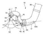
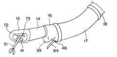
図5に示すように前記先端硬性部13の先端面には観察窓である観察用レンズカバー(以下、先端観察カバーと略記する)41、照明窓である照明用レンズカバー(以下、先端照明カバーと略記する)42、前記第1処置具導入口39aから挿通される内視鏡用処置具である例えば把持鉗子51等が導出される前記第1処置具挿通チャンネル50aに連通する処置具導出口である先端開口43が設けられている。 As shown in FIG. 5, an observation lens cover (hereinafter abbreviated as a tip observation cover) 41 as an observation window and an illumination lens cover (hereinafter referred to as a tip illumination cover) as an illumination window are provided on the tip surface of the tip
また、前記可撓管先端部16の先端面には前記第2湾曲部15の基端部が固定されるとともに、観察窓である観察用レンズカバー(以下、中途部観察カバーと略記する)44、照明窓である照明用レンズカバー(以下、中途部照明カバーと略記する)45、前記第2処置具導入口39bから挿通される内視鏡用処置具である例えば高周波スネア52等が導出される第2処置具挿通チャンネル50bに連通する処置具導出口である可撓管開口46が設けられている。 In addition, a proximal end portion of the
前記第1湾曲部14は、前記湾曲ノブ35UD、35LRが回動操作されることによって上下方向、左右方向に湾曲動作する。前記第2湾曲部15は、前記湾曲ノブ36が回動操作されることによって上下方向に湾曲動作する。前記可撓管湾曲部17は、前記湾曲ノブ37が回動操作されることによって左右方向に湾曲動作する。 The
なお、本実施形態においては、前記先端観察カバー41の光軸及び前記中途部観察カバー44の光軸が、ユニット挿入具3が直線状態において該ユニット挿入具の長手軸方向に対して平行になるように設けられている。 In the present embodiment, the optical axis of the
図5及び図6に示すように例えば、前記第1湾曲部14を下方向に湾曲動作させ、前記第2湾曲部15を前記第1湾曲部14の湾曲方向とは逆方向である上方向に湾曲動作させることによって、前記先端開口43の一点鎖線に示す導出方向を、前記可撓管先端部16の一点鎖線に示す中心軸線に対して略垂直な向きに設定することが可能である。 As shown in FIGS. 5 and 6, for example, the
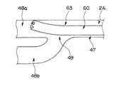
図6に示すように前記挿入部10内には、前記長孔38に連通するユニット挿通路47が設けられている。このユニット挿通路47には前記観察ユニット2が挿通される。このユニット挿通路47の中途部には分岐部49が形成されている。この分岐部49では、前記先端観察カバー41方向に向かう第1挿通路48aと、前記中途部観察カバー44方向に向かう第2挿通路48bとに分岐する。本実施形態においては前記分岐部49を可撓管湾曲部17内に設けている。 As shown in FIG. 6, a
前記観察ユニット2を前記ユニット挿通路47内に挿通配置した状態で、前記基端操作部26を例えば長孔38内でこの長孔38に沿って摺動移動させることによって、前記観察ユニット2は進退移動する。そして、この観察ユニット2の先端面が前記分岐部49に位置するとき、必要に応じて前記基端操作部26に設けられている操作レバー33を操作する。すると、前記観察ユニット2の先端部分が直線状態或いは湾曲状態に変化して、前記観察ユニット2を実線の矢印に示す第1挿通路48a側又は破線の矢印に示す第2挿通路48b側に選択的に導くことができる。 In a state where the
なお、前記観察ユニット2の先端硬性部先端面が前記分岐部49にさしかかった否かは前記LED照明30で照らされている部位を撮像している撮像装置29の観察画像によって確認する。つまり、術者は、観察ユニット2からモニタ6に送られた観察画像を観察しながら、操作レバー33の湾曲操作を選択的に行うことにより、観察ユニット2を所望する挿通路48a、48bに自在に挿入することができる。 Whether or not the distal hard surface of the distal end portion of the
前記観察ユニット2を前記第1挿通路48a側に挿通させて、前記先端観察カバー41の端面に観察ユニット2の先端面を密着配置させることによって先端観察カバー41を通して観察を行える。また、前記観察ユニット2を前記第2挿通路48b側に挿通させて、前記中途部観察カバー44の端面に前記観察ユニット2の先端面を配置することによって中途部観察カバー44を通しての観察を行うことができる。 Observation can be performed through the
つまり、観察カバー41、44を通して観察ユニット2でとらえた被検部位の観察画像がモニタ6の画面上に表示される。 That is, an observation image of the region to be examined captured by the
なお、前記先端硬性部13及び前記可撓管先端部16に設けられている照明カバー42、45には照明光学系を構成する前記ライトガイドファイバ束の先端面が配置されている。このため、前記ライトガイド口金4cの端面に集光された照明光は、前記ユニバーサルコード12、操作部11及び挿入部10内を挿通するこのライトガイドファイバ束を介して伝送され、前記照明カバー42、45を通して被検部位に向かって照射されている。 The illumination covers 42 and 45 provided at the distal end
上述のように構成した内視鏡1を備える内視鏡装置の作用を説明する。 The operation of the endoscope apparatus including the
まず、観察ユニット2を、ユニット挿入具3の操作部11に形成されている長孔38から挿通路47内に挿通する。このとき、前記ビデオプロセッサ5を動作状態にして、LED照明30を点灯状態にするとともに、撮像装置29を撮像状態にする。すると、前記モニタ6の画面上に、挿通路47内を移動する観察ユニット2の撮像装置29でとらえた観察画像が表示される。このモニタ6に表示される観察画像を観察しながら、前記観察ユニット2を第1挿通路48a内に配置し、前記先端硬性部13に設けた先端観察カバー41を通して観察を行える状態にする。 First, the
次に、光源装置4を動作させて前記照明カバー42、45から照明光を照射させる。そして、前記モニタ6の画面上に表示される先端観察カバー41を通して撮像された観察画像を観察しながら前記ユニット挿入具3の挿入部10を体腔内に挿通していく。このとき、操作部11に設けられている湾曲ノブ35UD、35LR、36、37等は適宜操作される。 Next, the
次いで、前記図5及び図6に示すように前記挿入部10の先端面を目的部位に対峙させる。そして、組織の切除を行うため、前記処置具導入部39の第1処置具導入口39aから把持鉗子51を挿通し、第2処置具導入口39bから高周波スネア52を挿通していく。 Next, as shown in FIGS. 5 and 6, the distal end surface of the
しばらくすると、前記先端硬性部13の先端開口43より把持鉗子51が体腔内に導出され、前記可撓管先端部16の可撓管開口46から高周波スネア52が導出される。 After a while, the grasping
ここで、モニタ6上に表示される前記先端観察カバー41を通して撮像された観察画像を観察しながら高周波スネア52の位置調整を行う。続いて、前記基端操作部26及び操作レバー33の操作を行って第1挿通路48a内に配置されていた観察ユニット2を第2挿通路48b内に移動配置させる。このことによって、前記モニタ6の画面上に中途部観察カバー44を通して撮像した観察画像が表示される。 Here, the position of the high-
このとき、この観察画像を観察しながら把持鉗子51を操作して処置部位の把持を行い、その後、把持鉗子51の移動操作或いは湾曲動作によって吊り上げ操作を行い、高周波スネア52による切除を開始する。この切除のとき、必要に応じ前記観察ユニット2を第1挿通路48a側或いは第2挿通路48b側に移動させる。 At this time, the grasping
切除時、観察ユニット2を第1挿通路48a側に移動させることによって、切除部全体を上方から観察して、切除箇所及び範囲が適切であるか否か、或いは、高周波スネア52の絞り具合からどの程度切除が進んでいる等の確認を行える。このことによって、より確実な切除が可能になる。 At the time of excision, the entire excision part is observed from above by moving the
また、本実施形態においては、前記観察ユニット2を第1挿通路48a或いは第2挿通路48bに移動させて観察方向の変更を行う間、処置具の操作やユニット挿入具3の位置、姿勢を調整する等の操作等を行っていない。つまり、ユニット挿入具3の挿入部10の挿入状態を変化させることや、体組織を把持している状態等を一定に保持した状態のままで、観察ユニット2を移動させることによって観察方向を変更している。したがって、処置を行っている間の操作性が向上されている。 In the present embodiment, while the
このように、内視鏡を、対物レンズ群及び撮像装置を有する軟性の観察ユニットと、この観察ユニットが挿通配置される挿通路を挿入部に設けたユニット挿入具とで構成し、このユニット挿入具の有する挿通路に分岐部を設け、分岐されているそれぞれの挿通路の先端部に、観察ユニットの先端面が密着配置される観察カバーを配置したことによって、体腔内に挿通されて、湾曲動作されたユニット挿入具の挿入部挿入状態を変化させることなく、挿通路内に挿通されている観察ユニットを移動させることで、複数の観察方向の観察画像を取得して処置を行うことができる。 Thus, the endoscope is composed of a flexible observation unit having an objective lens group and an imaging device, and a unit insertion tool in which an insertion path through which the observation unit is inserted is provided in the insertion portion. A bifurcation is provided in the insertion passage of the device, and an observation cover in which the distal end surface of the observation unit is arranged in close contact with the distal end of each branched insertion passage is inserted into the body cavity and curved. By moving the observation unit inserted in the insertion path without changing the insertion part insertion state of the operated unit insertion tool, it is possible to perform treatment by acquiring observation images in a plurality of observation directions. .
また、先端硬性部と可撓管先端部との間に設けた第1湾曲部を下方向に、そして第2湾曲部を上方向に湾曲させるなど、複数の湾曲部をそれぞれ適宜湾曲動作させて、所望の観察状態を得ることができる。このことによって、可撓管先端部の観察窓の視野に対して、先端開口から導出させた処置具が垂直に進退させることや、先端部の観察窓の視野に対して、可撓管開口から導出させた処置具が垂直に進退させることが可能になる。 In addition, a plurality of bending portions may be appropriately bent, for example, the first bending portion provided between the distal end rigid portion and the flexible tube distal end portion may be bent downward and the second bending portion may be bent upward. A desired observation state can be obtained. As a result, the treatment tool derived from the distal end opening moves forward and backward with respect to the visual field of the observation window at the distal end of the flexible tube, or from the flexible tube opening with respect to the visual field of the observation window at the distal end. The derived treatment instrument can be advanced and retracted vertically.
さらに、可撓管湾曲部を設けたことによって、先端硬性部の先端面のみならず、可撓管先端部に設けた可撓管開口を自由に目的部位に向けることができる。このことによって、処置時の操作性がさらに向上する。 Furthermore, by providing the flexible tube bending portion, not only the distal end surface of the distal end rigid portion but also the flexible tube opening provided at the distal end portion of the flexible tube can be freely directed to the target site. This further improves the operability during treatment.
そして、湾曲部を増やすことにより、可撓管先端部の観察カバーの観察視野に対し、先端開口又は可撓管開口から導出される処置具を、自在に様々な方向に向けて処置時の操作性の改善を図れる。 Then, by increasing the bending portion, the treatment tool derived from the distal end opening or the flexible tube opening can be freely directed in various directions with respect to the observation field of the observation cover of the flexible tube distal end portion. Improve sex.
なお、本実施形態においては、先端硬性部13に先端開口43を設け、可撓管先端部16に可撓管開口46を設けるとともに、操作部11の処置具導入部39に前記開口43、36に対応する第1処置具導入口39a及び第2処置具導入口39bを設けた構成を示しているが、例えば、解剖学的に膨隆状になった部位に対して針で穿刺を行い、針が組織に刺さったまま裏側まで完全に貫通しているか否かを確認するような用途の場合には、裏側に回り込む観察光学系だけあればよい。つまり、ユニット挿入具3に設ける穿刺を行う針が導出される処置具導出口である開口を、先端構成部13又は可撓管先端部16の一方に設ける構成であってもよい。 In the present embodiment, the distal end
また、本実施形態においては、ユニット挿入具3の先端硬性部13と可撓管先端部16との間に第1湾曲部14及び第2湾曲部15を設けるとともに、可撓管先端部16の後方側に可撓管湾曲部17を設ける構成としているが、例えば先端硬性部13と可撓管先端部16との間に第1湾曲部14又は第2湾曲部15の一方を設ける構成や、先端硬性部13と可撓管先端部16との間に第1湾曲部14又は第2湾曲部15の少なくとも一方或いは3つ以上の湾曲部を設ける構成、可撓管先端部16の後方側にだけ可撓管湾曲部17を設ける構成等、湾曲部を適宜組み合わせてユニット挿入具を構成するようにしてもよい。 In the present embodiment, the
上述した実施形態においては前記挿通路47の分岐部49に配置されている観察ユニット2を第1挿通路48a側又は第2挿通路48b側に向けて案内する際、操作レバー33の操作によって観察ユニット2の先端部を湾曲状態又は直線状態に変化させていた。このため、観察ユニット2のユニット挿入部20の先端側部にユニット関節駒24、先端関節駒31、操作用ワイヤ32を設けるとともに基端部に操作レバー33を設けていた。このため、観察ユニット2の構成が複雑であった。このため、観察ユニット2の観察性能を低下させることなく、前記ユニット挿入部20の構成の簡略化や外径を細径にする観察ユニット2が望まれている。そして、観察ユニット又は挿通路の分岐部を以下のように構成することによって、観察ユニット2の構成の簡略化或いは外径の細径化を図れる。 In the embodiment described above, when the
図7ないし図10は挿入部の簡略化を図った観察ユニットの構成にかかり、図7は曲がり癖部を有する観察ユニットを説明する図、図8は第2挿通路に観察ユニットを導く状態を説明する図、図9は第1挿通路に観察ユニットを導く状態を説明する図、図10はレンズカバー近傍に配置したガイドパイプの作用を説明する図である。 FIGS. 7 to 10 are related to the structure of the observation unit in which the insertion portion is simplified, FIG. 7 is a diagram for explaining the observation unit having a curved hook portion, and FIG. 8 is a state in which the observation unit is guided to the second insertion path. FIG. 9 is a diagram for explaining a state in which the observation unit is guided to the first insertion path, and FIG. 10 is a diagram for explaining the action of the guide pipe disposed in the vicinity of the lens cover.
図7に示すように観察ユニット2Aの挿入部60を細長なシース部61で構成する。そして、このシース部61内に前記対物レンズ群28、撮像装置29及び信号ケーブル34に加え、前記LED照明30の代わりに例えばライトガイドファイバ束62を配設する。このライトガイドファイバ束62は前記対物レンズ群28の周囲に配設されるように構成されている。また、前記観察ユニット2Aの挿入部60の先端部に、予め、自然状態で一方向に対して湾曲する曲がり癖部63を設けておく。 As shown in FIG. 7, the
このことによって、前記観察ユニット2Aの挿入部60の先端面が挿通路47の分岐部49に位置しているとき、図示しない手元側を把持して適宜捻り操作を行うことによって、二点鎖線に示すように観察ユニット2Aの先端部の向きが変化する。 As a result, when the distal end surface of the
具体的には、前記観察ユニット2Aの先端面が挿通路47の分岐部49に位置しているときに捻り操作を行うことにより、図8に示すように前記観察ユニット2Aの先端面が第2挿通路48b側に対峙した状態、或いは、図9に示すように前記観察ユニット2Aの先端面が第1挿通路48aの側壁面に対峙した状態等に変化する。このとき、前記モニタ6の画面上には、前記観察ユニット2Aの先端面が第2挿通路48bに対峙してとらえた前記第2挿通路48bに向かう開口の観察画像或いは第1挿通路48aの側壁面をとらえた観察画像等が表示される。 Specifically, by performing a twisting operation when the distal end surface of the
したがって、術者は、前記モニタ6に表示される観察画像から観察ユニット2Aの先端の位置を把握して、挿通させるべき挿通路の判断を行うことができる。そして、前記モニタ6の画面上に開口の観察画像が表示されている状態で、挿入部60を押し込み操作することによって、観察ユニット2Aは挿通路48bに挿通される。また、前記モニタ6の画面上に側壁面の観察画像が表示されている状態で、挿入部60を押し込み操作することによって、観察ユニット2Aは挿通路48aに挿通される。 Therefore, the surgeon can grasp the position of the tip of the
なお、図10に示すように前記先端硬性部13及び前記可撓管先端部16の観察カバー41、44の基端面側の所定位置には、前記観察ユニット2Aの先端部が嵌合配置される硬質部材で形成したガイドパイプ59が設けられている。このガイドパイプ59内に観察ユニット2Aの先端部分が挿入配置されることによって、前記シース部61の曲がり癖部63が矯正されて、この観察ユニット2Aの先端面が前記観察カバー41、44に対して密着配置された状態になる。つまり、ガイドパイプ59を設けることによって、曲がり癖部63の設けられている観察ユニット2Aの前方視野が確実に確保される。 As shown in FIG. 10, the distal end portion of the
また、前記挿入部60を把持している術者が、観察ユニット2Aに設けられている曲がり癖部63の位置を容易に判断することができるように、前記シース部61の基端部外表面に前記シース部61の曲がり癖部63の方向を告知する指標(不図示)等を設けるようにしてもよい。 Further, the outer surface of the proximal end portion of the
このことによって、前記ユニット挿入具3の挿通路47内に観察ユニット2Aが挿通されているとき、指標を確認することによって、シース部61の曲がり癖部63の方向を把握しながら挿通作業を行えるので、観察ユニットの挿通作業性が向上する。 Thus, when the
このように、観察ユニットのシース部に曲がり癖部を設けることによって、観察ユニット挿入部の簡略化を図れ、かつ挿通路の分岐部に到達した観察ユニットを捻り操作によって選択的に第1挿通路側又は第2挿通路側に導びくことができる。 As described above, the bending unit is provided in the sheath portion of the observation unit, so that the observation unit insertion portion can be simplified, and the observation unit that has reached the branch portion of the insertion passage is selectively twisted by the first insertion passage. To the side or the second insertion passage side.
図11及び図12は挿入部の簡略化を図った観察ユニットにおけるユニット挿入具が有する挿通路の分岐部に設ける挿通路切替え機構にかかり、図11は挿通路切替え機構の構成及び観察ユニットを第2挿通路に導入する状態を説明する図、図12は挿通路切替え機構の構成及び観察ユニットを第1挿通路に導入する状態を説明する図である。 11 and 12 are related to an insertion path switching mechanism provided at a branch portion of the insertion path of the unit insertion tool in the observation unit that simplifies the insertion section. FIG. 11 illustrates the configuration of the insertion path switching mechanism and the observation unit. FIG. 12 is a diagram for explaining the state of introduction into the two insertion passages, and FIG. 12 is a view for explaining the configuration of the insertion passage switching mechanism and the state of introducing the observation unit into the first insertion passage.
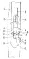
図11に示すように前記分岐部49に挿通路切替え機構を設けている。この挿通路切替え機構は、回動板64と、付勢部材65と、牽引操作ワイヤ66とで主に構成されている。前記回動板64は回動自在に配置されている。前記付勢部材65は、この回動板64を矢印方向に付勢する例えばバネ部材である。前記牽引操作ワイヤ66は、牽引操作することによって前記回動板64を前記付勢部材65の付勢力に抗して反矢印側に移動させる。 As shown in FIG. 11, an insertion path switching mechanism is provided at the
前記挿通路切替え機構の牽引操作ワイヤ66は図に示す状態のとき牽引操作されていない。したがって、前記回動板64は、前記付勢部材65の付勢力によって第1挿通路48aに通じる開口を塞ぐ閉位置に配置される。したがって、前記挿通路47の分岐部49に位置する観察ユニット2Bを押し進める操作を行ったとき、前記回動板64によって第1挿通路48a内への挿通が妨げられて、第2挿通路48bに導入される。 The pulling
これに対して、前記牽引操作ワイヤ66を牽引操作した場合には、図12に示すように前記回動板64は前記付勢部材65の付勢力に抗して移動されて、分岐部49に設けられている凹部67内に収納された状態になる。すると、前記第1挿通路48aに通じる開口が出現する。このことによって、前記挿通路47内の分岐部49に位置する観察ユニット2Bを押し進める操作を行ったとき、前記挿通路47内を直線的に移動して第1挿通路48a側に導入される。つまり、本実施形態においては、ユニット関節駒24、先端関節駒31、操作用ワイヤ32及び操作レバー33を設けることなく、かつ、曲がり癖部63を設けることなく観察ユニット2Bが構成されている。 On the other hand, when the pulling
このように、挿通路の分岐部に、回動板と、付勢部材と、牽引操作ワイヤとで構成される挿通路切替え機構を設けることによって、牽引操作ワイヤの手元操作によって、第1挿通路側に向かう開口を開状態又は閉状態に切り替えて、挿通路の分岐部に位置する観察ユニットを第1挿通路側又は第2挿通路側に選択的に導入させることができる。 As described above, by providing the insertion path switching mechanism including the rotation plate, the urging member, and the traction operation wire at the branch portion of the insertion path, the first insertion path can be operated by the hand operation of the traction operation wire. The observation unit located at the branch portion of the insertion passage can be selectively introduced to the first insertion passage side or the second insertion passage side by switching the opening toward the side to an open state or a closed state.
また、観察ユニットの挿入部の構成のさらなる簡略化を図ることかできる。 In addition, the configuration of the insertion unit of the observation unit can be further simplified.
図13ないし図15はユニット挿入具の他の構成例にかかり、図13はユニット挿入具の概略構成を説明する図、図14はユニット挿入具の作用例を説明する図、図15はユニット挿入具の他の作用例を説明する図である。 FIGS. 13 to 15 relate to another configuration example of the unit insertion tool, FIG. 13 is a diagram illustrating a schematic configuration of the unit insertion tool, FIG. 14 is a diagram illustrating an operation example of the unit insertion tool, and FIG. It is a figure explaining other examples of operation of a tool.
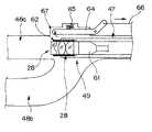
図13に示すように本実施形態のユニット挿入具3Aでは、上述した実施形態で示したように先端硬性部13の先端面に観察カバー41を配置する代わりに、先端硬性部13の例えば側面に観察カバー41を配置している。また、前記第1挿通路48aの先端部に前記観察カバー41から入射する観察像の光軸を90度折り曲げるプリズム71を設けている。 As shown in FIG. 13, in the
つまり、本実施形態においては、前記先端観察カバー41の光軸は、ユニット挿入具3が直線状態において該ユニット挿入具の長手軸方向に対して直交するように設けられ、前記中途部観察カバー44の光軸はユニット挿入具3が直線状態において該ユニット挿入具の長手軸方向に対して平行になるように設けられている。 That is, in the present embodiment, the optical axis of the
このことによって、前記第1挿通路48a内を挿通させた観察ユニットの先端面を前記プリズム71に密着配置させることにより、側視方向の観察を行える。また、前記観察ユニットを第2挿通路48b内に挿通させて前記中途部観察カバー44に観察ユニットの先端面を密着配置させることによって前述と同様に直視方向の観察を行える。 As a result, the distal end surface of the observation unit inserted through the
この構成のとき、図14に示すように前記ユニット挿入具3Aを構成する先端硬性部13の側面に前記観察カバー41に加えて、前記側視の視野方向と略同方向に処置具を突出させる起上台72を配置した先端開口73を設ける構成にし、かつ、前記先端硬性部13と前記可撓管先端部16との間には第1湾曲部14又は第2湾曲部15の一方を設ける。すると、前記図5で示したように第1湾曲部14を下方向に湾曲させるとともに第2湾曲部15を第1湾曲部14の湾曲方向とは逆方向に湾曲させることなく、前記第1湾曲部14を湾曲動作させるだけで前記先端開口73の処置具導出方向と、前記可撓管先端部16の軸方向線とを略垂直な向きに設定することを容易に行える。 In this configuration, as shown in FIG. 14, in addition to the
この構成によれば、前記先端硬性部13の先端開口73から把持鉗子51を側視観察方向に突出させて体組織を把持した状態にし、この把持鉗子51を引き寄せる操作、或いは第1湾曲部15を上方向に湾曲動作させることにより、体組織を可撓管先端部16の軸方向線と略垂直な方向に吊り上げられる。この吊り上げの際、観察ユニットを第1挿通路48a側に配置することにより、把持鉗子51が体組織を把持した状態で吊り上げていく様子の観察を行える。 According to this configuration, the grasping
また、この吊り上げた状態で、前記可撓管先端部16の可撓管開口46から例えば電気ナイフ74を導出させることによって、吊り上げられている体組織の切除を行える。この切除のとき、前記観察ユニットを第2挿通路48b側の中途部観察カバー44に移動配置させることによって、前記可撓管先端部16の先端面から直視観察を行って、前記電気ナイフ74による切除の様子の観察を行える。 Further, in this suspended state, for example, the
この後、再び前記観察ユニットを、第1挿通路48a側の観察カバー41に移動配置させ、切除組織を把持している側から観察して切除を行うことにより、切除範囲の確認及び切除部周囲の状態の確認を確実に行える。これらのことによって、ユニット挿入具3Aの位置、姿勢を調整する等の操作を行うことなく、かつ、体組織を把持している状態等を一定に保持したままで、観察ユニットの移動によって観察方向を変更して、より確実な切除作業を行える。 Thereafter, the observation unit is moved again to the
なお、図15に示すようにユニット挿入具3Bに設ける観察カバー41を先端硬性部13の傾斜面75に配置し、第1挿通路48aの先端部に前記観察カバー41から入射する観察像の光軸を所定の角度に折り曲げるプリズム(不図示)を設ける構成にしてもよい。 As shown in FIG. 15, the
このことによって、前記第1挿通路48a内を挿通させた観察ユニットの先端面を図示しないプリズムに密着配置させることによって斜視方向の観察を行える。一方、この観察ユニットを第2挿通路48b内に挿通させて前記中途部観察カバー44に密着配置させることによって、前述と同様に直視方向の観察を行える。この構成のときも、前記先端硬性部13と前記可撓管先端部16との間に第1湾曲部14又は第2湾曲部15の一方を設けた構成にする。 As a result, observation in the perspective direction can be performed by placing the distal end surface of the observation unit inserted through the
本図においては可撓管先端部16の可撓管開口46から把持鉗子51を前方に突出させて体組織を吊り上げ、この状態で、前記先端硬性部13の先端開口73から例えば電気ナイフ74を導出させて、吊り上げられている体組織の切除を行える。このとき、前記観察ユニットを第2挿通路48b側、第1挿通路48a側の観察カバー41、44に適宜移動配置させて観察を行う。このことによって、図14と同様の作用及び効果を得られる。 In this figure, the grasping
また、上述した実施形態においては、ユニット挿入具に設けた照明光学系からの照明光で照らされている被検部位の観察像を観察ユニットの撮像装置で撮像して観察する構成としている。しかし、前記観察ユニットを分岐部を確認するためだけの狭い範囲を小さな光量で照らす照明光学系ではなく、体腔内を広範囲に明るく照らすことのできるレンズ構成を備えた観察のための照明光学系と観察光学系とを有する内視鏡ユニットとして構成し、この内視鏡ユニットを前記挿通路に挿通させる構成にしてもよい。 Moreover, in embodiment mentioned above, it is set as the structure which images and observes the observation image of the to-be-tested part illuminated with the illumination light from the illumination optical system provided in the unit insertion tool with the imaging device of the observation unit. However, the illumination unit is not an illumination optical system that illuminates a narrow range with a small amount of light only for confirming a branching portion, but an illumination optical system for observation with a lens configuration that can illuminate a wide range of the body cavity brightly An endoscope unit having an observation optical system may be configured, and the endoscope unit may be inserted into the insertion path.
この構成によれば、内視鏡ユニットの先端面を、第1挿通路又は第2挿通路のレンズカバーに密着配置することにより、内視鏡ユニットの有する照明光学系からの照明光を被検部位に照射して、この内視鏡ユニットの観察光学系で観察画像を得られる。 According to this configuration, the distal end surface of the endoscope unit is placed in close contact with the lens cover of the first insertion path or the second insertion path, so that illumination light from the illumination optical system of the endoscope unit is examined. By irradiating the site, an observation image can be obtained by the observation optical system of the endoscope unit.
そして、内視鏡ユニットをユニット挿通路に挿通させる構成をとることによって、前記ユニット挿入具から照明光学系を構成するライトガイドファイバ束及び照明カバー等を不要にして、この内視鏡ユニットに対応する太径な挿通路の構成が可能になる。 Then, by adopting a configuration in which the endoscope unit is inserted into the unit insertion passage, the light guide fiber bundle and the illumination cover that constitute the illumination optical system are not required from the unit insertion tool, and this endoscope unit can be used. A large-diameter insertion passage can be configured.
図16ないし図20は本発明の第2実施形態にかかり、図16は先端硬性部の先端面と可撓管先端部の先端面に観察光学系、照明光学系及び処置具導出口を設けた内視鏡の構成及び作用を説明する図、図17は前記図16の内視鏡に対応するビデオプロセッサ及びモニタの構成例を説明する図、図18は前記図16の内視鏡に対応するビデオプロセッサ及びモニタの他の構成例を説明する図、図19は可撓管先端部の先端側に超音波観察部を設けた内視鏡を説明する図、図20は前記図19の内視鏡の作用を説明する図である。 16 to 20 are related to a second embodiment of the present invention, and FIG. 16 is provided with an observation optical system, an illumination optical system, and a treatment instrument outlet on the distal end surface of the distal rigid portion and the distal end surface of the flexible tube. FIG. 17 is a diagram illustrating a configuration example of a video processor and a monitor corresponding to the endoscope of FIG. 16, and FIG. 18 corresponds to the endoscope of FIG. FIG. 19 is a diagram for explaining another configuration example of the video processor and the monitor, FIG. 19 is a diagram for explaining an endoscope provided with an ultrasonic observation unit on the distal end side of the flexible tube distal end, and FIG. 20 is an endoscope for FIG. It is a figure explaining the effect | action of a mirror.
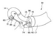
図16及び図17に示すように本実施形態の内視鏡80の挿入部81は、前記ユニット挿入具3と同様、先端側から順に先端硬性部13、第1湾曲部14、第2湾曲部15、可撓管先端部16、可撓管湾曲部17及び可撓管部18を連設して構成されている。前記挿入部81の基端に位置する把持部を兼ねる操作部82には湾曲ノブ35UD、35LR、36、37が設けられている。前記第1湾曲部14、第2湾曲部15及び可撓管湾曲部17は、前記湾曲ノブ35UD、35LR、36、37の操作によってそれぞれ独立して湾曲動作する。 As shown in FIGS. 16 and 17, the
前記先端硬性部13の先端面には先端観察系カバー83、先端照明系カバー84及び先端開口43が設けられている。前記可撓管先端部16の先端面には中途部観察系カバー85、中途部照明系カバー86及び可撓管開口46が設けられている。前記先端硬性部13の先端観察系カバー83及び前記可撓管先端部16の中途部観察系カバー85の基端側には観察光学系を構成する図示しない対物レンズ群及び撮像装置がそれぞれ配設されている。 A tip
前記先端観察系カバー83、85を通過して撮像装置に結像した光学像は、それぞれの撮像装置で電気信号に光電変換され、それぞれの撮像装置から延出している図示しない信号ケーブルを介してビデオプロセッサ5に伝送されるようになっている。 The optical image that has passed through the tip observation system covers 83 and 85 and formed on the imaging device is photoelectrically converted into an electrical signal by each imaging device, and via a signal cable (not shown) extending from each imaging device. It is transmitted to the
具体的には、それぞれの撮像装置から延出する信号ケーブルは、前記挿入部81内、前記操作部82内、この操作部82の側部から延出するユニバーサルコード87内を挿通している。そして、一方の信号ケーブルは第1電気ケーブル88aを介して切換装置89に伝送され、他方の信号ケーブルは光源装置4に着脱自在に接続される内視鏡コネクタ87aの側部に着脱自在に接続される第2電気ケーブル88bを介して前記切換装置89に入力される。この切換装置89ではそれぞれの信号ケーブル及び電気ケーブル88a、88bを介して伝送された電気信号を、前記操作部82に設けた切替手段である例えば画像切替スイッチ82aを操作することによって、選択的にビデオプロセッサ5に伝送する。なお、前記切換装置89とビデオプロセッサ5とは画像ケーブル90によって接続されている。 Specifically, signal cables extending from the respective imaging devices are inserted through the
上述のように構成した内視鏡80を備える内視鏡装置の作用を説明する。
前記内視鏡80においては、挿入部81を構成する可撓管湾曲部17を湾曲させることにより、胃のように内腔の大きな臓器内の被検部位に対してであっても可撓管先端部16の中途部観察系カバー85等を対向させられる。また、前記挿入部81は、第1湾曲部14と第2湾曲部15を独立して湾曲動作させられるので、先端硬性部13の先端面を可撓管先端部16の挿入軸方向に対して垂直に向けることも容易である。An operation of the endoscope apparatus including the
In the
例えば、前記図16に示すように先端硬性部13の先端開口43より把持鉗子51を突出させて組織を吊り上げ、可撓管先端部16の可撓管開口46より電気ナイフ74を突出させて、前記把持鉗子51で把持した部位の下方の切除を行うとき、前記画像切替スイッチ82aを適宜操作することにより、次のような効果が期待できる。 For example, as shown in FIG. 16, the grasping
前記モニタ6の画面上に先端硬性部13に設けた先端観察系カバー83を通した観察画像を表示させることにより、把持部位の様子や切除範囲の確認等を行えるようになる。 By displaying an observation image through the distal end observation system cover 83 provided on the distal end
一方、前記可撓管先端部16の中途部観察系カバー85を通した観察画像に切替え表示すれば、電気ナイフ74による切除の様子を観察しながら処置を行えるようになる。 On the other hand, if the display is switched to an observation image through the mid-section observation system cover 85 of the flexible tube
このように、先端硬性部及び可撓管先端部にそれぞれ撮像装置を設けるとともに、操作部にモニタに表示させる観察画像を切り替える切替スイッチを設けることによって、モニタに表示される観察画像を、先端硬性部の撮像装置でとらえた観察画像又は可撓管先端部の撮像装置でとらえた観察画像に瞬時に切り替えて確実な処置を迅速に行うことができる。 As described above, the imaging device is provided at the distal end rigid portion and the flexible tube distal end portion, and the observation switch displayed on the monitor is changed to the distal end rigid by providing the operation unit with the changeover switch for switching the observation image to be displayed on the monitor. It is possible to instantaneously switch to the observation image captured by the imaging device of the part or the observation image captured by the imaging device of the distal end portion of the flexible tube and perform a reliable treatment quickly.
なお、前記ユニバーサルコード87内には前記照明系カバー84、86に先端面が臨まれているライトガイドファイバ束も挿通されており、光源装置4に内視鏡用コネクタを接続することによって、このライトガイドファイバ束を介して照明光が供給されるようになっている。 In addition, a light guide fiber bundle whose front end faces the illumination system covers 84, 86 is also inserted into the
また、図18に示すように前記ユニバーサルコード87内を挿通して内視鏡コネクタ87b近傍まで延出されたそれぞれの信号ケーブルをこの内視鏡コネクタ87bの側部から2つの電気ケーブル91、92として延出するようにしてもよい。このとき、それぞれの電気ケーブル91、92を例えばコネクタ91a、92aを介して独立したビデオプロセッサ5A、5Bに接続する。そして、それぞれのビデオプロセッサ5A、5Bに対応するモニタ6A、6Bの画面上に前記先端観察系カバー83又は中途部観察系カバー85を通して撮像装置で撮像した観察画像を別々に同時に表示する。このことによって、切替操作を行うことなく、常に両観察画像を観察しながら処置を行うことができる。 Further, as shown in FIG. 18, each signal cable that passes through the
さらに、先端硬性部13に位置する先端観察系カバー83の視野方向を側視方向にするようにしてもよい。このとき、前記図14に示したユニット挿入具3Aと同様に先端硬性部13と可撓管先端部16との間に第1湾曲部14を設ける。このことによって、上述した実施形態と同様の作用及び効果を得られる。 Furthermore, the viewing direction of the tip observation system cover 83 located at the tip
又、図19及び図20に示すように前記可撓管先端部16に中途部観察系カバー85、及び中途部照明系カバー86を設ける代わりに、例えば超音波によるセクタ走査が可能な超音波観察部93を設け、この超音波観察部93で取得したエコーデータを図示しない超音波観測装置に伝送して、超音波断層画像を図示しないモニタの画面上に表示させる構成にしてもよい。 Further, as shown in FIGS. 19 and 20, instead of providing a midway
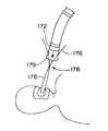
この構成によれば、例えば、先端硬性部13から導出させた把持鉗子51で把持した体組織を吊り上げた状態にして可撓管湾曲部17の可撓管開口46から穿刺針94を突出させて体組織に穿刺する場合、超音波観察部93によって得られる超音波断層画像によって体組織に穿刺された針先がどの深さまで到達しているかの確認等を行うことができる。 According to this configuration, for example, the body tissue grasped by the grasping
図21ないし図23は本発明の第3実施形態にかかり、図21は処置用内視鏡の挿入部先端部の構成を説明する斜視図、図22は処置用内視鏡の挿入部先端部の構成を説明する正面図、図23は処置用内視鏡の作用を説明する図である。 FIG. 21 to FIG. 23 are related to a third embodiment of the present invention, FIG. 21 is a perspective view for explaining the configuration of the distal end portion of the insertion portion of the treatment endoscope, and FIG. 22 is the distal end portion of the insertion portion of the treatment endoscope. FIG. 23 is a diagram for explaining the operation of the treatment endoscope.
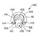
図21及び図22に示すように本実施形態の内視鏡100は細長で可撓性を有する内視鏡ユニット101と、この内視鏡ユニット101が配置されるユニット挿入具110とで構成されている。 As shown in FIGS. 21 and 22, the
前記ユニット挿入具110は挿入部断面形状が略C字形状に形成されている。このユニット挿入具110は、先端側より順に先端硬性部111、湾曲部112及び可撓管部113を連設して構成されている。前記先端硬性部111の先端面には、例えば一対の処置具導出口114、115が設けられている。また、前記湾曲部112は例えば左右方向に湾曲するように構成されている。なお、符号116は内周面側に突出した係入凸部である。 The
一方、前記内視鏡ユニット101は断面形状が略8の字形状に形成されている。この内視鏡ユニット101には例えば上下方向に湾曲する図示しない湾曲部が設けられている。この内視鏡ユニット110には前記係入凸部116が配置される凹部102が形成されている。この内視鏡ユニット101の先端面には観察光学系を構成する観察系カバー103、照明光学系を構成する照明系レンズカバー104及び処置具導出口105が設けられている。 On the other hand, the
前記内視鏡ユニット101は、前記ユニット挿入具110に対して独立して進退するように構成されている。つまり、図21に示すように内視鏡ユニット101の先端面と前記ユニット挿入具110の先端面とが面一致した状態から、図23に示すように内視鏡ユニット101の先端面をユニット挿入具110の先端面から突出した状態にすることができるようになっている。そして、前記内視鏡ユニット101が突出した状態のとき、湾曲動作させられる。 The
上述のように構成した内視鏡100の作用を説明する。
まず、内視鏡ユニット101の先端面とユニット挿入具110の先端面とを面一致させた状態の内視鏡100を目的部位に向けて挿入していく。そして、観察系カバー103を通して撮像された観察画像をモニタの画面上で確認しながら、内視鏡ユニット101をユニット挿入具110の先端面から突出させていく。The operation of the
First, the
次に、前記処置具導出口105から例えば把持鉗子51を導出させる。そして、モニタに表示されている観察画像を観察しながら体組織の把持を行い、その後、前記内視鏡ユニット101を引き戻す操作を行って、体組織を吊り上げた状態にする。 Next, for example, the grasping
次いで、前記ユニット挿入具110に設けられている処置具導出口114、115の少なくとも一方から例えば切除用ナイフ117を導出させる。この切除用ナイフ117が、内視鏡ユニット101の先端面より前方に導出されることによって、モニタの画面上に吊り上げられている状態の体組織ともにこの切除用ナイフ117が表示される。この状態で、手元操作を適宜行いながら、体組織の切除を行う。 Next, for example, a cutting
このように、内視鏡ユニットがユニット挿通具に対して独立し進退する構成にするとともに、内視鏡ユニット及びユニット挿通具に導出方向が一致した処置具導出口を設けることによって、内視鏡ユニットの視野画像で、内視鏡ユニット及びユニット挿入具の処置具導出口から導出される処置具を一定方向から常に観察することができるので、2つの処置具の協調操作を容易に行える。 Thus, the endoscope unit is configured to advance and retreat independently with respect to the unit insertion tool, and the endoscope unit and the unit insertion tool are provided with the treatment instrument outlet port having the same extraction direction, thereby providing an endoscope. Since the treatment tool derived from the endoscope unit and the treatment tool outlet of the unit insertion tool can always be observed from a certain direction in the field-of-view image of the unit, cooperative operation of the two treatment tools can be easily performed.
図24ないし図33(c)は本発明の第4実施形態にかかり、図24は内視鏡を構成する先端硬性部に進退自在に配設される先端フードを説明する図、図25は先端フードのフード凹部に体壁を引き込んだ状態を説明する図、図26は先端フードを最も手元側に移動させた状態を説明する図、図27はTバーが配置される穿刺針の構成を説明する図であり、図27(a)はパイプ形状の穿刺針及びこの穿刺針の貫通孔に配置されるTバーを説明する図、図27(b)はTバーを連結する連結糸と締め付け部材と締め付け具との関係を説明する図、図27(c)は穿刺針の貫通孔に配置されるプッシャーを説明する図、図28は先端フードの他の構成を説明する図、図29は先端フードを進退され他の機構を説明する図、図30はシリンダヘッドが内圧の上昇に伴って移動している状態を説明する図、図31は操作部に設けた牽引ノブ及び回動リングの動作を説明する図、図32は先端フードの胃内で使用している状態を説明する図、図33はTバーによる縫合を説明する図であり、図33(a)は2つ目のTバーを突出させている状態を説明する図、図33(b)はTバーの間隔を狭めて締め付けを行う様子を説明する図、図33(c)は2か所の突出したTバーを引き寄せた状態を説明する図である。 FIGS. 24 to 33 (c) are related to a fourth embodiment of the present invention. FIG. 24 is a view for explaining a tip hood that can be freely advanced and retracted in the tip rigid portion constituting the endoscope. FIG. FIG. 26 is a diagram illustrating a state in which the body wall is drawn into the hood recess of the hood, FIG. 26 is a diagram illustrating a state in which the tip hood is moved to the nearest side, and FIG. 27 is a diagram illustrating the configuration of the puncture needle on which the T bar is disposed. FIG. 27A is a view for explaining a pipe-shaped puncture needle and a T-bar disposed in the through-hole of the puncture needle, and FIG. 27B is a connection thread and a fastening member for connecting the T-bar. FIG. 27C is a diagram for explaining a pusher disposed in the through hole of the puncture needle, FIG. 28 is a diagram for explaining another configuration of the tip hood, and FIG. FIG. 30 is a diagram for explaining another mechanism by moving the hood forward and backward. FIG. FIG. 31 is a view for explaining the operation of the pulling knob and the rotating ring provided in the operation portion, and FIG. 32 is used in the stomach of the tip hood. FIG. 33 is a diagram for explaining stitching by a T-bar, FIG. 33 (a) is a diagram for explaining a state in which a second T-bar is projected, and FIG. FIG. 33C is a diagram for explaining a state in which tightening is performed by narrowing the interval between the T bars, and FIG. 33C is a diagram for explaining a state in which the two protruding T bars are drawn.
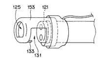
図24に示すように本実施形態の内視鏡120の先端硬性部121には観察用カバー122、照明用カバー123、穿刺針挿通用孔124、前記観察用カバー122を洗浄するための洗浄用ノズル125が配置されている。前記穿刺針挿通用孔124には穿刺針126が挿通配置されるようになっている。 As shown in FIG. 24, the distal end
前記観察用カバー122の基端側には図示しない対物レンズ群及び撮像装置が配置され、この撮像装置からは信号ケーブルが延出している。したがって、前記観察用カバー122を通してこの撮像装置に結像された光学像は、光電変換された画像信号を信号ケーブルを介してビデオプロセッサに伝送することによって映像信号に信号処理されるようになっている。 An objective lens group and an imaging device (not shown) are arranged on the proximal end side of the
図24及び図25に示すように前記先端硬性部121には先端フード130が被覆配置されている。この先端フード130は、前記先端硬性部121の側面部に形成されている挿入軸方向に細長な複数のフードガイド127に沿って進退する構成になっている。また、この先端フード130の基端部にはフード牽引ワイヤ(以下、牽引ワイヤと略記する)128の先端部が固定されている。この牽引ワイヤ128は、前記内視鏡120の挿入部側周面に配置されているワイヤ案内チューブ129内を挿通して後述する図31に示す操作部に設けられている牽引ノブ161に基端部が固定されている。したがって、術者がこの牽引ノブ161を操作して牽引ワイヤ128を進退移動させることによって、前記先端フード130が図25の矢印に示すように進退動作する。 As shown in FIGS. 24 and 25, the distal end
前記先端フード130の側周部にはこの内視鏡120の長手軸方向に対して直交する切り欠き部で構成したフード凹部131が設けられている。このフード凹部131内に前記先端硬性部121の先端面121aが配置されるようになっている。 A
前記フード凹部131の先端側内壁面132には手元方向に向かって突出した複数の爪状フック133が設けられている。この爪状フック133は、前記先端フード130を手元側に移動させた際、体組織をこのフード凹部131内に引き込むためのものである。このため、体組織に引っ掛かるようにフック先端部を先鋭に形成し、かつ先端がフード凹部131内の切り欠き底面側を向くように曲げ形状で形成されている。 A plurality of claw-
図26に示すように前記先端フード130を最も手元側に牽引配置したとき、前記先端側内壁面132は前記先端硬性部121の先端面に密着することなく、この先端面近傍に位置するように設定されている。また、前記先端硬性部121の先端面には前記爪状フック133に対応する軸方向に細長なフック収納溝135が形成されている。したがって、前記先端フード130が最も手元側に位置しているとき、このフック収納溝135内に前記爪状フック133が格納される。 As shown in FIG. 26, when the
図27(a)ないし図27(c)に示すように前記穿刺針126は中空パイプで形成されている。そして、この穿刺針126の貫通孔内には2つのTバー141が挿入配置されるようになっている。この2つのTバー141は連結糸142によって連結されている。この連結糸142の中途部には締め付け部材143が設けられている。この締め付け部材143は、締め付け具144の先端に係止されており、この締め付け具144を操作部側から操作することによって、前記Tバー141間の距離を狭めることができるようになっている。 As shown in FIGS. 27 (a) to 27 (c), the
図27(c)に示すように前記穿刺針126の貫通孔内に配置されるTバー141の後方側には前記操作部まで延出するプッシャー145が内蔵されている。このプッシャー145を、術者が押し出し操作することによって、穿刺針126の貫通孔内に配置されていたTバー141が外部に押し出されるようになっている。 As shown in FIG. 27 (c), a
なお、本実施形態においては前記先端フード130を視野確保のため透明部材で形成しているが、図28に示すように前方に視野確保のフード開口部152を形成した開口付き先端フード153として構成するようにしてもよい。 In the present embodiment, the
また、前記先端フード130の進退動作は前記牽引ワイヤ128の進退操作に限定されるものではなく、例えば、図29及び図30に示すように構成して空気圧で進退させる構成であってもよい。 The forward / backward movement of the
図29に示すように本実施形態においては先端フード154を、フード部155と、このフード部155が摺動自在に配置されるフードベース156とで構成されている。このフードベース156にはシリンダ部157が設けられている。一方、前記フード部155の端部には例えばゴム製のシリンダヘッド158が設けられている。 As shown in FIG. 29, in the present embodiment, the
前記シリンダヘッド158は、前記シリンダ部157に対し摺動可能に配置される。そして、前記シリンダ部157と前記シリンダヘッド158とによって囲まれる空間は外部から密閉された密閉空間になっている。前記フードベース156には前記密閉空間に連通するポート159が設けられている。このポート159には送気チューブ160の一端部が連結されている。この送気チューブ160の他端部は内圧操作手段である図示しないポンプ或いは手動操作のシリンジに連結されている。 The
前記ポンプにより前記シリンダ部157に空気が供給されると、前記密閉空間内の圧力が高まる。すると、前記フード部155が手元側に移動していた場合、内圧の上昇に伴って図30に示すようにシリンダヘッド158が矢印に示す前方方向に移動する。このことによって、前記シリンダヘッド158に一体であるフード部155が前方方向に移動してフード凹部131が開状態になる。ここで、前記密閉空間内の圧力を下げると、前記シリンダヘッド158は基端方向に移動される。このことによって、前記フード部155が手元側に移動して前記フード凹部131が再び閉状態になる。 When air is supplied to the
図31に示すように操作部には処置具導入部、湾曲操作ノブに加え、前記牽引ワイヤ128を進退操作する、或いは、前記送気チューブ160の中途部に設けられる図示しない電磁弁に連動するレバー161及び前記穿刺針126を進退移動させる回動リング162が設けられている。前記レバー161は、矢印に示すように回動操作することによって、前記先端フード130又は先端フード154を構成するフード部155が進退移動する。また、前記回動リング162を矢印に示すように回動操作することによって、図示しないワイヤ部材が進退されて穿刺針126が前記穿刺針挿通用孔124から突没するようになっている。 As shown in FIG. 31, in addition to the treatment instrument introduction section and the bending operation knob, the operation section is operated to advance and retract the pulling
ここで、前記先端フード130を先端硬性部121に配置した内視鏡120の作用を説明する。
まず、内視鏡を胃等の体腔内の目的部位まで挿入するとき、先端フード130を最も手前に引きよせた状態にして爪状フック133をフック収納溝135内に格納しておく。このことによって、挿入時に、爪状フック133が体壁に引っかかることが防止される。Here, the operation of the
First, when the endoscope is inserted up to a target site in a body cavity such as the stomach, the claw-shaped
この状態で、前記操作部の湾曲ノブの手元操作或いは挿入部の捻り操作を行いながら、挿入部163の湾曲部164を湾曲させて、前記先端硬性部121を目標部位近傍まで挿入し、引き続き、手元操作によって先端フード130を体壁に接触させる。 In this state, while performing the hand operation of the bending knob of the operation portion or the twisting operation of the insertion portion, the bending
次に、術者は、レバー161を操作する。すると、図32に示すように先端フード130が開状態になってフード凹部131を出現させる。その後、再び前記レバー161を操作して前記先端フード130を閉状態方向に移動させていく。すると、この動作に伴い、先端フード130の先端側内壁面132に設けられている爪状フック133に体壁が引っかかった状態で移動されていく。このことによって、先端フード130のフード凹部131内に体壁が引き込まれていく。 Next, the surgeon operates the
このとき、図示を省略するが、内視鏡の先端面に操作部より延出した吸引孔の開口を設けておくことにより、先端フード130を閉じながら吸引を行うことによって、より多く、より確実に体壁を先端フード130内に引き込むことが可能になる。 At this time, although not shown in the drawings, by providing a suction hole opening extending from the operation portion on the distal end surface of the endoscope, suction is performed while the
次いで、前記先端フード130をさらに手元側に引き寄せる。すると、前記先端フード130の先端側内壁面132と前記先端硬性部121の先端面121aとの間で、フード凹部131内に引き込まれた体腔内組織が押圧された状態で挟持される。 Next, the
次に、この押圧挟持状態で前記回動リング162を操作し、前記穿刺針挿通用孔124から穿刺針126を突出させる。このとき、前記先端側内壁面132と前記先端面121aとで体壁が押圧挟持されているので、この体壁が逃げることなく、安定、確実な穿刺を行える。 Next, the
前記穿刺針126の貫通孔内には前記図27(a)で示した2ヶのTバー141が格納されている。ここで、前記穿刺針126の体壁への穿刺が完了した後、前記図27(c)に示すようにプッシャー145を先端方向に押し出し操作する。すると、前記穿刺針126の貫通孔内から1つ目のTバー141が突出される。 In the through hole of the
前記1つ目のTバー141を突出させた後、前記先端硬性部121を移動させ、上述した手順で体壁の別の部分を押圧挟持する。そして、再度、同様に穿刺を行い、図33(a)に示すように2つ目のTバー141を別の体壁に突出させる。 After the first T-
前記2つのTバー141を突出させた後、図33(b)に示すように締め付け具144を手元側より引き絞る操作を行って、Tバー141間の間隔を狭め締め付けを行う。すると、図33(c)に示すように2か所の部位に突出されていたTバー141が引き寄せ、この状態で縫合を行う。 After projecting the two
なお、穿刺縫合を行う部位によっては、予め、2つの穿刺部間の距離が分かっている場合がある。このような場合には、前記連結糸142の長さを、その部位間の距離に合わせて調整をしておく。このことによって、締め付け具144を用いて締め付けする工程を省ける。 Depending on the site where the puncture suture is performed, the distance between the two puncture portions may be known in advance. In such a case, the length of the connecting
このように、先端硬性部に進退操作可能な先端フードを配置し、この先端フードに体壁等を引っ掛ける爪状フックを設けることによって、先端フードの移動によって目的部位の体壁等をフード凹部に引き込むことができる。 As described above, the distal end hood that can be moved forward and backward is disposed on the distal end rigid portion, and the nail-like hook that hooks the body wall and the like is provided on the distal end hood. You can pull in.
また、フード凹部内に体壁等を引き込んだ状態で、さらに先端フードを手元側に移動させて体壁等を押圧挟持することによって、この状態で穿刺を行うことによって体壁が逃げることを防止して、安定、確実な穿刺を行うことができる。 In addition, while the body wall is pulled into the hood recess, the tip hood is moved further toward the hand side to press and hold the body wall to prevent the body wall from escaping by puncturing in this state Thus, stable and reliable puncture can be performed.
さらに、穿刺針による穿刺を確実に行えることによって、体腔内組織の縫合を確実に行うことができる。このため、例えば出血部位の血管を締め付けて止血を行う手技や、穿孔部を閉じる手技が可能になる。 Furthermore, since the puncture with the puncture needle can be reliably performed, the tissue in the body cavity can be reliably sutured. For this reason, for example, a technique for tightening a blood vessel at a bleeding site to stop hemostasis and a technique for closing a perforated part are possible.
又、前記先端フード及び穿刺針の進退操作を、操作部に設けたレバー及び回動リングで行う構成にしたことによって、術者は湾曲操作ノブを手元操作しながら、穿刺を行うことができる。このことによって、先端硬性部の位置を移動させる操作等を容易に行える。 Further, since the forward and backward operation of the tip hood and the puncture needle is performed by a lever and a rotating ring provided in the operation unit, the operator can perform puncture while operating the bending operation knob at hand. Thereby, an operation for moving the position of the distal end hard portion can be easily performed.
なお、前記レバー161を操作して送気チューブ160の電磁弁を開閉操作する場合でも同様な手技が可能である。 A similar procedure is possible even when the
図34ないし図39は本発明の第5実施形態にかかり、図34はフード凹部内に先端面に対向するよう穿刺針を設けた先端フードを説明する図、図35は針受け部の構成例を説明する図、図36は針受け部の他の構成を説明する図、図37は針受け部の別の構成を説明する図、図38は先端フードに配置されている穿刺針の作用を説明する図であり、図38(a)はフード凹部内に体組織を引き込んだ状態を説明する図、図38(b)はフード凹部内に引き込んだ体組織に穿刺針を刺入するとともにこの穿刺針の先端が針受け部に固定された状態を説明する図、図38(c)は穿刺針が針ベースから外れた状態を説明する図、図38(d)は連結糸を体組織に残した状態で内視鏡を抜去している状態を説明する図、図39はノットプッシャーによって結び目を体腔内に送り込む様子を説明する図である。 34 to 39 are related to a fifth embodiment of the present invention. FIG. 34 is a view for explaining a tip hood provided with a puncture needle so as to face the tip surface in the hood recess, and FIG. 35 is a configuration example of a needle receiving portion. FIG. 36 is a diagram for explaining another configuration of the needle receiving portion, FIG. 37 is a diagram for explaining another configuration of the needle receiving portion, and FIG. 38 shows the action of the puncture needle disposed on the tip hood. FIG. 38 (a) is a diagram for explaining the state in which the body tissue has been drawn into the hood recess, and FIG. 38 (b) is a diagram in which a puncture needle is inserted into the body tissue drawn into the hood recess. FIG. 38 (c) is a diagram illustrating a state in which the tip of the puncture needle is fixed to the needle receiving portion, FIG. 38 (c) is a diagram illustrating a state in which the puncture needle is detached from the needle base, and FIG. FIG. 39 is a diagram illustrating a state in which the endoscope is removed in the state where it is left, FIG. 39 is a knot pusher Thus is a diagram illustrating a manner in which feed the knot into the body cavity.
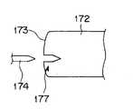
図34に示すように本実施形態の先端フード170のフード凹部171内には、先端硬性部172の先端面173に対向するように突出する穿刺針174が設けられている。この穿刺針174は、針ベース175に対して着脱可能に配置されている。また、穿刺針174の基端部には連結糸176が連結されている。この連結糸176は、内視鏡挿入部内に設けられている図示しない糸通路を介して端部を体外に延出している。一方、前記先端硬性部の先端面には前記穿刺針174を保持固定する後述する針受け部が設けてある。 As shown in FIG. 34, a
前記針受け部177は図35ないし図37に示すように構成されている。図35に示す針受け部177は、例えばゴム、スポンジといった軟質部材で形成されており、前記穿刺針174が刺さると、この穿刺針174は前記軟質部材の摩擦力によって軟質部材中に固定される。図36に示す針受け部177は前記穿刺針174の針先に対応するテーパ状の穴部が有し、穿刺針174がこのテーパー状穴部に嵌合固定されるようになっている。図37に示す針受け部177は、先端硬性部172の先端面173から突出するパイプ状シースであり、このパイプ状シースの側面にスリットを形成して弾性変形可能になっている。そして、前記パイプ状シースの孔径を穿刺針174の外径より細径に形成している。このため、穿刺針174が刺さってパイプ状シース内に係入配置されと、パイプ状シースが弾性変形して穿刺針を付勢力で固定する。 The
ここで、前記先端フード170に配置されている穿刺針174の作用を説明する。
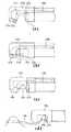
まず、図38(a)に示すように先端フード170のフード凹部171を開状態位置から手元側に移動させる操作を行って、体壁をフード凹部171内に引き込む。次に、図38(b)に示すように先端フード170の先端側内壁面と先端硬性部172の先端面173との間で体組織を挟み込むように先端フード170を後退させる。このとき、同時に穿刺針174にて穿刺が行われる。そして、前記フード凹部131が閉状態になることによって、前記穿刺針174の先端が針受け部177に突き刺さり、この穿刺針174が針受け部177に固定された状態になる。Here, the operation of the
First, as shown in FIG. 38A, an operation of moving the
この状態で、図38(c)に示すように前記先端フード170を再び開状態にする。すると、前記穿刺針174の針先が前記針受け部177に固定されているため、この穿刺針174の前記針ベース175から外れた状態になる。ここで、図38(d)に示すように内視鏡を体腔内より抜去していくことによって、この内視鏡とともに連結糸176の端部が連結されている穿刺針174が体外に引き出される。 In this state, the
次いで、図39に示すように体外にて結び目178を形成し、この結び目を例えばノットプッシャー179によって、その結び目178を体腔内に送り込む。このことによって、体組織の縫合を行うことができる。 Next, as shown in FIG. 39, a
なお、前記ノットプッシャー179は、内視鏡挿入部の先端硬性部172に連結糸176が挿通若しくは係止する溝が設けられたキャップが取り付けられて構成される。このようにして、連結糸176のみで、即ち、他の留置物なしで体腔内組織の縫合を行える。 The
このように、先端フードに対して取り外し可能な穿刺針を配置する一方、内視鏡挿入部の先端硬性部に前記穿刺針が穿刺されたときこの穿刺針を保持固定する針受け部を設けたことによって、操作性を損なわれることなく確実に体壁の縫合を行うことができる。 As described above, the removable puncture needle is arranged with respect to the distal end hood, while the needle receiving portion for holding and fixing the puncture needle when the distal end rigid portion of the endoscope insertion portion is punctured is provided. As a result, the body wall can be reliably sutured without impairing operability.
図40ないし図42は本発明の第6実施形態にかかり、図40は固定部と可動部とで構成された先端硬性部を説明する図、図41は閉状態の先端硬性部を示す図、図42は開状態の先端硬性部を示す図である。 FIGS. 40 to 42 are related to a sixth embodiment of the present invention, FIG. 40 is a diagram for explaining a tip rigid portion constituted by a fixed portion and a movable portion, and FIG. 41 is a diagram showing a tip rigid portion in a closed state, FIG. 42 is a view showing the distal end hard portion in the open state.
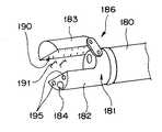
図40ないし図42に示すように本実施形態の内視鏡挿入部180を構成する先端硬性部181は固定部182と可動部183とで構成されている。そして、前記固定部182の先端面には観察用カバー184、照明用カバー185が配置されている。 As shown in FIGS. 40 to 42, the distal end
前記固定部182は先端硬性部181として構成されており、前記可動部183はこの固定部182にリンク機構186を介して連結されている。このことにより、前記可動部183は、前記固定部182に対して平行な状態を保持して、徐々に開状態になっていく。そして、前記可動部183の開閉動作は、操作部に設けられる図示しないノブを術者が操作することにより行われるようになっている。 The fixed
図41に示すように内視鏡挿入部180を体腔内への挿入するとき、前記可動部183と固定部182とを閉じた状態にする。そして、術者の手元操作によって、図40に示すように可動部183を開状態にすると、固定部182の内平面187及び壁面188が露出し、この壁面188に設けられている先端開口189が露出状態になる。 As shown in FIG. 41, when the
前記先端開口189からは各種処置具を突出させることができるようになっている。即ち、前記先端開口189は処置具導出口であり、前記可動部183が開状態のときにだけ、この可動部183と前記固定部182との間で開口するように構成されている。 Various treatment instruments can be projected from the
図42に示すように前記可動部183側の内平面190には複数の溝が設けられており、これらの溝には各々ステープラー191が格納されている。前記ステープラー191は金属部材で略コ字形状に形成され、その両先端を鋭利に形成して所定の力量においてて両針が畳まれる構成になっている。これらステープラー191は、図示しない操作部を操作することにより前記可動部183から、外部に射出される構成になっている。 As shown in FIG. 42, a plurality of grooves are provided in the
そして、前記ステープラー191を射出すると同時に、前記可動部183は固定部182に近づくように閉状態になる。このことによって、可動部183と固定部182との間にステープラー191が挟まれ、平面で形成された固定部182の内平面187において前記ステープラー191の両針が押し畳まれるようになっている。 At the same time as the
ここで、固定部182と可動部183とで構成した先端硬性部を備えた内視鏡の作用を説明する。
内視鏡挿入部180の湾曲部192を操作して先端硬性部181を目的部位に近づける。ここで、可動部183を開き、先端開口189より、例えば把持鉗子193を突出させて目的部位の体組織を把持する。そして、体組織を前記可動部183と前記固定部182との間に配置する。この体組織を前記可動部183と前記固定部182の間に引き込んだ状態でステープラー191を射出する。すると、前記可動部183が閉状態になるように移動して、ステープラー191の針が組織に刺されるとともに、その後、針が押し畳まれる。このことによって、体組織がステープラー191によって針止めすることができる。Here, the operation of the endoscope provided with the distal end rigid portion constituted by the fixed
The bending
本実施形態においては、前記可動部183が固定部182に対して平行移動する構成であるため、開閉動作に必要なスペースは、固定部182を配置するためのスペースの他に可動部183が可動する分だけあればよい。仮に、固定部182に対してピポット状に可動部を配置して開閉する構成にした場合には、開閉する部材の自由端から固定端までを半径とした回転に必要な分だけスペースが必要になる。 In the present embodiment, since the
このように、固定部に対して平行移動して開閉する可動部にステープラーを設けることによって、大きな臓器のみでなく、管腔など狭い臓器の希望の個所を容易に結紮することができる。 Thus, by providing the stapler in the movable part that moves parallel to the fixed part and opens and closes, not only a large organ but also a desired part of a narrow organ such as a lumen can be easily ligated.
また、縫合機能を、湾曲部を有す内視鏡挿入部に内蔵させることによって、この湾曲部を使用して、容易にステープラーを目的位置に配置すること及び所望の向きに配置することができる。このことによって、より容易に穿刺縫合が可能になる。 Further, by incorporating the suturing function in the endoscope insertion portion having a curved portion, the stapler can be easily arranged at a target position and arranged in a desired direction using the curved portion. . This makes it possible to puncture sutures more easily.
なお、本発明は、以上述べた実施形態のみに限定されるものではなく、発明の要旨を逸脱しない範囲で種々変形実施可能である。 Note that the present invention is not limited to the above-described embodiments, and various modifications can be made without departing from the spirit of the invention.
[付記]
以上詳述したような本発明の上記実施形態によれば、以下の如き構成を得ることができる。[Appendix]
According to the embodiment of the present invention as described above in detail, the following configuration can be obtained.
(1)可撓性の挿入部に処置具が挿通される処置具挿通チャンネルを有する処置用内視鏡において、
照明光学系及び撮像装置を備えた観察光学系を一面に設けた挿入部の先端部と、
照明光学系及び撮像装置を備えた観察光学系を一面に設けた挿入部の中途部と、
前記先端部の一面又は前記中途部の一面の少なくとも一方に設けられ、前記処置具挿通チャンネルに連通する処置具導出口と、
前記挿入部の基端部に配設された操作部に設けられ、前記処置具挿通チャンネルに連通する処置具導入口と、
を具備する処置用内視鏡。(1) In a treatment endoscope having a treatment instrument insertion channel through which a treatment instrument is inserted into a flexible insertion portion,
A distal end portion of an insertion portion provided with an observation optical system including an illumination optical system and an imaging device on one surface;
A middle portion of the insertion portion provided with an observation optical system including an illumination optical system and an imaging device on one side;
A treatment instrument outlet that is provided on at least one of one surface of the distal end portion or one surface of the midway portion and communicates with the treatment instrument insertion channel;
A treatment instrument introduction port provided in an operation section disposed at a proximal end portion of the insertion section and communicating with the treatment instrument insertion channel;
A treatment endoscope comprising:
この構成によれば、挿入部の先端部の一面及び中途部の一面にそれぞれ設けた観察光学系及び照明光学系によって内視鏡観察を行える。また、挿入部の先端部の一面又は中途部の一面に設けた処置具導出口から処置具が導出される。 According to this configuration, endoscope observation can be performed by the observation optical system and the illumination optical system provided on one surface of the distal end portion and one surface of the middle portion of the insertion portion, respectively. In addition, the treatment tool is led out from a treatment tool lead-out port provided on one surface of the distal end portion or one halfway portion of the insertion portion.
(2)前記挿入部の前記先端部と前記中途部との間、又は、前記中途部の後方側の少なく一方に、手元側操作で独立して湾曲動作する湾曲部を設けた付記1に記載の処置用内視鏡。(2) The
(3)前記先端部の一面に設けられた照明光学系及び観察光学系の光軸又は前記中途部の一面に設けられた照明光学系及び観察光学系の光軸の少なくとも一方は、前記挿入部が直線状態において該挿入部の長手軸方向に対して平行である付記1又は付記2に記載の処置用内視鏡。(3) At least one of the optical axis of the illumination optical system and the observation optical system provided on one surface of the tip portion or the optical axis of the illumination optical system and the observation optical system provided on one surface of the intermediate portion is the insertion portion. The treatment endoscope according to
(4)挿入部の先端部の一面及び挿入部の中途部の一面に撮像装置を備えた観察光学系を設けた処置用内視鏡と、
前記先端部及び前記中途部に設けた撮像装置で光電変換した電気信号を映像信号に信号処理するビデオプロセッサと、
このビデオプロセッサで処理された映像信号を受けて、観察画像を表示するモニタと、
前記先端部及び前記中途部に設けた撮像装置で光電変換した電気信号を前記ビデオプロセッサに伝送して、前記モニタの画面上に観察画像を表示させる切換装置と、
を具備する処置用内視鏡装置。(4) a treatment endoscope provided with an observation optical system including an imaging device on one surface of the distal end portion of the insertion portion and one surface of the middle portion of the insertion portion;
A video processor that performs signal processing on an electric signal photoelectrically converted by an imaging device provided at the tip and the middle part into a video signal;
A monitor for receiving an image signal processed by the video processor and displaying an observation image;
A switching device for transmitting an electrical signal photoelectrically converted by an imaging device provided at the tip and the middle portion to the video processor and displaying an observation image on the screen of the monitor;
A treatment endoscope apparatus comprising:
(5)前記内視鏡の操作部に、前記モニタの画面上に前記先端部の撮像装置がとらえた観察画像又は前記中途部に設けた撮像装置がとらえた観察画像を切替え表示させる切替手段を設けた付記4に記載の処置用内視鏡装置。(5) Switching means for causing the operation unit of the endoscope to switch and display an observation image captured by the imaging device at the distal end portion or an observation image captured by the imaging device provided in the middle portion on the monitor screen. The treatment endoscope apparatus according to
(6)挿入部の先端部の一面及び挿入部の中途部の一面に撮像装置を備えた観察光学系を設けた処置用内視鏡と、
前記先端部に設けた撮像装置で光電変換した電気信号を映像信号に信号処理する第1のビデオプロセッサと、
前記中途部に設けた撮像装置で光電変換した電気信号を映像信号に信号処理する第2のビデオプロセッサと、
前記第1のビデオプロセッサで処理された映像信号を受けて、観察画像を表示する第1のモニタと、
前記第2のビデオプロセッサで処理された映像信号を受けて、観察画像を表示する第2のモニタと、
を具備する処置用内視鏡装置。(6) a treatment endoscope provided with an observation optical system provided with an imaging device on one surface of the distal end portion of the insertion portion and one surface of the insertion portion;
A first video processor that performs signal processing of an electrical signal photoelectrically converted by an imaging device provided at the tip portion into a video signal;
A second video processor that processes an electrical signal photoelectrically converted by the imaging device provided in the middle part into a video signal;
A first monitor for receiving an image signal processed by the first video processor and displaying an observation image;
A second monitor for receiving an image signal processed by the second video processor and displaying an observation image;
A treatment endoscope apparatus comprising:
(7)可撓性の挿入部に処置具が挿通される処置具挿通チャンネルを有する処置用内視鏡において、
照明光学系及び撮像装置を備えた観察光学系を一面に設けた挿入部の先端部と、
超音波観測部設けた挿入部の中途部と、
前記先端部の一面又は前記中途部の一面の少なくとも一方に設けられ、前記処置具挿通チャンネルに連通する処置具導出口と、
前記挿入部の基端部に配設された操作部に設けられ、前記処置具挿通チャンネルに連通する処置具導入口と、
を具備する処置用内視鏡。(7) In a treatment endoscope having a treatment instrument insertion channel through which a treatment instrument is inserted into a flexible insertion portion,
A distal end portion of an insertion portion provided with an observation optical system including an illumination optical system and an imaging device on one surface;
The middle part of the insertion part provided with the ultrasonic observation part,
A treatment instrument outlet that is provided on at least one of one surface of the distal end portion or one surface of the midway portion and communicates with the treatment instrument insertion channel;
A treatment instrument introduction port provided in an operation section disposed at a proximal end portion of the insertion section and communicating with the treatment instrument insertion channel;
A treatment endoscope comprising:
(8)前記挿入部の前記先端部と前記中途部との間、又は、前記中途部の後方側の少なく一方に、手元側操作で独立して湾曲動作する湾曲部を設けた付記7に記載の処置用内視鏡。(8) The additional portion 7 is provided with a bending portion that performs a bending operation independently by a hand side operation between the distal end portion of the insertion portion and the midway portion or at least one of the rear side of the midway portion. Endoscope for treatment.
(9)内視鏡の挿入部の長手軸方向に対して細長に形成したなフードガイドと、
長手方向中途部に形成され、配置孔に連通する長手軸方向に対して直交する方向の切り欠き部と、
前記挿入部の側周面に配置したワイヤ案内チューブと、
このワイヤ案内チューブ内に挿通配置され、一端部が前記先端フードに固定されるフード牽引ワイヤと、
を具備する先端フード。(9) a hood guide that is elongated with respect to the longitudinal axis direction of the insertion portion of the endoscope;
A notch in a direction perpendicular to the longitudinal axis direction formed in the middle in the longitudinal direction and communicating with the arrangement hole;
A wire guide tube disposed on a side peripheral surface of the insertion portion;
A hood pulling wire that is inserted into the wire guide tube and has one end fixed to the tip hood;
A tip hood comprising:
(10)前記切り欠き部の先端側内壁面に爪状フックを配設した付記9記載の先端フード。(10) The tip hood as set forth in appendix 9, wherein a claw-like hook is disposed on the tip side inner wall surface of the notch.
(11) 前記切り欠き部に、前記内視鏡の挿入部内を挿通する処置具チャンネルの開口が連通する付記9又は付記10に記載の先端フード。(11) The distal end hood according to appendix 9 or
(12) 前記フード牽引ワイヤの他端部が連結される、該フード牽引ワイヤを牽引操作するための操作レバーを、前記内視鏡の操作部に設けた付記9記載の先端フード。(12) The distal end hood according to appendix 9, wherein an operation lever for pulling the hood puller wire, to which the other end of the hood puller wire is coupled, is provided in the operation unit of the endoscope.
(13) 内視鏡の挿入部先端部に固設されるシリンダ部を設けたフードベースと、
このフードベースの前記シリンダ部内に摺動自在に配置されるシリンダヘッドを有する、
長手方向中途部に切り欠き部が形成されたフード部と、
前記挿入部の側周面に配置され、先端部が前記シリンダ部に連通し、基端部が内圧操作手段に連結される送気チューブと、
を具備する先端フード。(13) A hood base provided with a cylinder portion fixed to the distal end portion of the insertion portion of the endoscope;
A cylinder head slidably disposed in the cylinder portion of the hood base;
A hood having a notch formed in the middle in the longitudinal direction;
An air supply tube disposed on a side peripheral surface of the insertion portion, a distal end portion communicating with the cylinder portion, and a proximal end portion coupled to an internal pressure operating means;
A tip hood comprising:
(14) 前記切り欠き部の先端側内壁面に爪状フックを配設した付記13記載の先端フード。(14) The tip hood according to
(15) 前記切り欠き部に、前記内視鏡の挿入部内を挿通する処置具チャンネルの開口が連通する付記13又は付記14記載の先端フード。(15) The tip hood according to
(16) 前記送気チューブの基端部がポンプに連結される構成において、
前記送気チューブの中途部に電磁弁を設ける一方、この電磁弁の開閉操作を指示する操作レバーを前記内視鏡の操作部に設けた付記13記載の先端フード。(16) In the configuration in which the proximal end portion of the air supply tube is connected to a pump,
14. The distal end hood according to
前記付記9乃至付記16は、内視鏡操作部において縫合、穿刺を行う際、複数の操作部を同時に扱うことなく、容易かつ確実に行える先端フードを提供することを目的にしている。 The supplementary notes 9 to 16 are intended to provide a tip hood that can be easily and reliably handled without simultaneously handling a plurality of operation parts when performing suturing and puncturing in an endoscope operation part.
内視鏡を経口的に体腔内に挿入して結紮の処置を行う場合、例えばこの内視鏡の先端部に、針、糸、糸取り手段を備えた先端フードが取り付けられる。そして、結紮の処置を行うために穿刺針を体組織に穿刺する。このとき、内視鏡と体組織とが固定された状態でないため、穿刺の瞬間、内視鏡と体組織との間隔が離れてしまうことがある。すると、体組織が針先から逃げることにより、安定した穿刺を行うことが難しくなる可能性がある。また、針、糸など複数の独立した部材を同時に取り扱う際には、煩雑な操作が要求され、熟練を要する手技になっていた。 When an endoscope is orally inserted into a body cavity to perform ligation treatment, for example, a distal end hood provided with a needle, a thread, and thread take-up means is attached to the distal end portion of the endoscope. Then, a puncture needle is punctured into the body tissue in order to perform ligation treatment. At this time, since the endoscope and the body tissue are not in a fixed state, the interval between the endoscope and the body tissue may be separated at the instant of puncturing. Then, the body tissue may escape from the needle tip, which may make it difficult to perform stable puncture. Further, when handling a plurality of independent members such as needles and threads at the same time, a complicated operation is required, which is a skill requiring skill.
そして、例えば特公平6−44913号公報には、外科手術において必要とされる組織の縫合に特に応用され、患者の身体に外部切開をなす必要なく患者の身体内部において使用することができ、患者の身体の外部から例えば内視鏡手段によって制御することのできる組織に縫合部を形成する装置が示されている。しかし、特公平6−44913号公報に示される組織に縫合部を形成する装置においても、煩雑な操作が要求され、熟練を要する手技になっている。 And, for example, Japanese Patent Publication No. 6-44913 is applied particularly to sutures of tissues required in surgery, and can be used inside a patient's body without the need to make an external incision in the patient's body. An apparatus is shown for forming a suture in tissue that can be controlled, eg, by endoscopic means, from outside the body. However, the apparatus for forming a stitched portion in the tissue disclosed in Japanese Patent Publication No. 6-44913 requires a complicated operation and requires a skill.
1…処置用内視鏡 2…観察光学ユニット 3…ユニット挿入具
10…ユニット挿入部 13…先端硬性部 14…第1湾曲部
15…第2湾曲部 16…可撓管先端部 17…可撓管湾曲部
18…可撓管部 38…長孔 39…処置具導入部
39a、39b…処置具導入口 41…観察用レンズカバー 43…先端開口
44…観察用レンズカバー 46…可撓管開口 47…ユニット挿通路
48a、48b…挿通路 49…分岐部 50a、50b…処置具挿通チャンネル
代理人 弁理士 伊藤 進DESCRIPTION OF
DESCRIPTION OF
DESCRIPTION OF
Claims (7)
Translated fromJapanese前記ユニット挿入具のユニット挿通チャンネルは第1挿通路及び第2挿通路に分岐する分岐部を有し、第1挿通路の端部開口に配設される観察窓が先端部の一面に設けられ、第2通路の端部開口に配設される観察窓が中途部の一面に設けられる構成において、
前記ユニット挿入具は、
手元側の基端部に、前記観察光学ユニットを導入するための光学ユニット導入口と、処置具が挿通される少なくとも1つの処置具導入口を有し、
前記先端部の一面又は前記中途部の一面の少なくとも一方に、前記処置具導入口から延出される前記処置具挿通チャンネルに連通する処置具導出口を備えることを特徴とする処置用内視鏡。A treatment endoscope comprising at least an elongated and flexible observation optical unit having an observation optical system, a unit insertion channel through which the observation optical unit is inserted, and a unit insertion tool having a treatment instrument insertion channel through which a treatment instrument is inserted. A mirror,
The unit insertion channel of the unit insertion tool has a branch portion that branches into a first insertion passage and a second insertion passage, and an observation window disposed in an end opening of the first insertion passage is provided on one surface of the distal end portion. In the configuration in which the observation window disposed in the end opening of the second passage is provided on one surface of the middle part,
The unit inserter is
An optical unit introduction port for introducing the observation optical unit, and at least one treatment instrument introduction port through which the treatment instrument is inserted, at the proximal end of the proximal side;
A treatment endoscope characterized in that a treatment instrument outlet opening communicating with the treatment instrument insertion channel extending from the treatment instrument introduction port is provided on at least one of the one surface of the distal end portion or the middle portion.
前記ユニット挿通チャンネル内を挿通する前記観察光学ユニットの挿通方向を、前記第1挿通路方向又は前記第2挿通路方向に選択的に切り替えるチャンネル切替機構を設けたことを特徴とする請求項1に記載の処置用内視鏡。In the branch part where the unit insertion channel into which the observation optical unit is inserted branches into the first insertion path and the second insertion path,
The channel switching mechanism for selectively switching the insertion direction of the observation optical unit that is inserted through the unit insertion channel to the first insertion path direction or the second insertion path direction is provided. The treatment endoscope as described.
回動自在に配置される回動板と、
この回動板を第1挿通路に向かう開口を塞ぐように付勢する付勢部材と、
牽引操作によって前記回動板を前記付勢部材の付勢力に抗して移動させる牽引操作ワイヤと、
を具備することを特徴とする請求項5に記載の処置用内視鏡。The channel switching mechanism is
A rotating plate arranged rotatably,
An urging member that urges the rotating plate to close the opening toward the first insertion path;
A traction operation wire that moves the rotating plate against the urging force of the urging member by a traction operation;
The treatment endoscope according to claim 5, further comprising:
Applications Claiming Priority (1)
| Application Number | Priority Date | Filing Date | Title |
|---|---|---|---|
| US50514703P | 2003-09-23 | 2003-09-23 |
Publications (2)
| Publication Number | Publication Date |
|---|---|
| JP2005095590A JP2005095590A (en) | 2005-04-14 |
| JP4533695B2true JP4533695B2 (en) | 2010-09-01 |
Family
ID=34710030
Family Applications (1)
| Application Number | Title | Priority Date | Filing Date |
|---|---|---|---|
| JP2004224504AExpired - Fee RelatedJP4533695B2 (en) | 2003-09-23 | 2004-07-30 | Treatment endoscope |
Country Status (2)
| Country | Link |
|---|---|
| US (1) | US7662089B2 (en) |
| JP (1) | JP4533695B2 (en) |
Families Citing this family (472)
| Publication number | Priority date | Publication date | Assignee | Title |
|---|---|---|---|---|
| US9167959B1 (en)* | 2010-03-26 | 2015-10-27 | Optech Ventures, Llc | Illumination for enhanced contrast in debridement apparatus and method |
| US9060770B2 (en) | 2003-05-20 | 2015-06-23 | Ethicon Endo-Surgery, Inc. | Robotically-driven surgical instrument with E-beam driver |
| US20070084897A1 (en) | 2003-05-20 | 2007-04-19 | Shelton Frederick E Iv | Articulating surgical stapling instrument incorporating a two-piece e-beam firing mechanism |
| JP2005169009A (en)* | 2003-12-15 | 2005-06-30 | Olympus Corp | Endoscope system and endoscope |
| US11819192B2 (en) | 2004-03-23 | 2023-11-21 | Boston Scientific Scimed, Inc. | In-vivo visualization system |
| ES2552252T3 (en) | 2004-03-23 | 2015-11-26 | Boston Scientific Limited | Live View System |
| US7922654B2 (en) | 2004-08-09 | 2011-04-12 | Boston Scientific Scimed, Inc. | Fiber optic imaging catheter |
| US20050272977A1 (en)* | 2004-04-14 | 2005-12-08 | Usgi Medical Inc. | Methods and apparatus for performing endoluminal procedures |
| US8992420B2 (en)* | 2004-04-14 | 2015-03-31 | Usgi Medical, Inc. | Methods and apparatus for off-axis visualization |
| US8277373B2 (en)* | 2004-04-14 | 2012-10-02 | Usgi Medical, Inc. | Methods and apparaus for off-axis visualization |
| US11998198B2 (en) | 2004-07-28 | 2024-06-04 | Cilag Gmbh International | Surgical stapling instrument incorporating a two-piece E-beam firing mechanism |
| US9072535B2 (en) | 2011-05-27 | 2015-07-07 | Ethicon Endo-Surgery, Inc. | Surgical stapling instruments with rotatable staple deployment arrangements |
| US11890012B2 (en) | 2004-07-28 | 2024-02-06 | Cilag Gmbh International | Staple cartridge comprising cartridge body and attached support |
| JP4355671B2 (en)* | 2004-10-04 | 2009-11-04 | 規方 田熊 | Gastrostomy tube reinsertion device |
| US11653816B2 (en)* | 2004-10-11 | 2023-05-23 | Nitesh Ratnakar | Next generation endoscope |
| US8182422B2 (en) | 2005-12-13 | 2012-05-22 | Avantis Medical Systems, Inc. | Endoscope having detachable imaging device and method of using |
| JP4813082B2 (en)* | 2005-04-15 | 2011-11-09 | オリンパスメディカルシステムズ株式会社 | Endoscope system |
| EP1881781A2 (en)* | 2005-05-16 | 2008-01-30 | Kenneth Binmoeller | Systems and methods to facilitate endoscopic interventions |
| WO2006123397A1 (en)* | 2005-05-16 | 2006-11-23 | Olympus Medical Systems Corp. | Endoscope system, control program for endoscope system, and control method for endoscope system |
| US7669746B2 (en) | 2005-08-31 | 2010-03-02 | Ethicon Endo-Surgery, Inc. | Staple cartridges for forming staples having differing formed staple heights |
| US7934630B2 (en) | 2005-08-31 | 2011-05-03 | Ethicon Endo-Surgery, Inc. | Staple cartridges for forming staples having differing formed staple heights |
| US10159482B2 (en) | 2005-08-31 | 2018-12-25 | Ethicon Llc | Fastener cartridge assembly comprising a fixed anvil and different staple heights |
| US11246590B2 (en) | 2005-08-31 | 2022-02-15 | Cilag Gmbh International | Staple cartridge including staple drivers having different unfired heights |
| US20070066869A1 (en)* | 2005-09-21 | 2007-03-22 | David Hoffman | Endoscopic assembly including cap and sheath |
| US20070106317A1 (en) | 2005-11-09 | 2007-05-10 | Shelton Frederick E Iv | Hydraulically and electrically actuated articulation joints for surgical instruments |
| WO2007063904A1 (en)* | 2005-12-01 | 2007-06-07 | Olympus Medical Systems Corp. | Guiding long medical member and long medical device |
| US8617054B2 (en)* | 2006-01-13 | 2013-12-31 | Olympus Medical Systems Corp. | Medical treatment endoscope |
| US9289112B2 (en)* | 2006-01-13 | 2016-03-22 | Olympus Corporation | Medical treatment endoscope having an operation stick formed to allow a procedure instrument to pass |
| US9308049B2 (en)* | 2006-01-13 | 2016-04-12 | Olympus Corporation | Medical treatment endoscope |
| US8556805B2 (en)* | 2006-01-13 | 2013-10-15 | Olympus Medical Systems Corp. | Rotational force transmission mechanism, force-attenuating apparatus, medical device, and medical instrument-operation mechanism |
| US8439828B2 (en)* | 2006-01-13 | 2013-05-14 | Olympus Medical Systems Corp. | Treatment endoscope |
| US9173550B2 (en)* | 2006-01-13 | 2015-11-03 | Olympus Corporation | Medical apparatus |
| WO2007087421A2 (en) | 2006-01-23 | 2007-08-02 | Avantis Medical Systems, Inc. | Endoscope |
| JP2007195688A (en)* | 2006-01-25 | 2007-08-09 | Fujinon Corp | Endoscope insertion assisting appliance |
| US8708213B2 (en) | 2006-01-31 | 2014-04-29 | Ethicon Endo-Surgery, Inc. | Surgical instrument having a feedback system |
| US20110295295A1 (en) | 2006-01-31 | 2011-12-01 | Ethicon Endo-Surgery, Inc. | Robotically-controlled surgical instrument having recording capabilities |
| US8820603B2 (en) | 2006-01-31 | 2014-09-02 | Ethicon Endo-Surgery, Inc. | Accessing data stored in a memory of a surgical instrument |
| US11793518B2 (en) | 2006-01-31 | 2023-10-24 | Cilag Gmbh International | Powered surgical instruments with firing system lockout arrangements |
| US20120292367A1 (en) | 2006-01-31 | 2012-11-22 | Ethicon Endo-Surgery, Inc. | Robotically-controlled end effector |
| US8186555B2 (en) | 2006-01-31 | 2012-05-29 | Ethicon Endo-Surgery, Inc. | Motor-driven surgical cutting and fastening instrument with mechanical closure system |
| US7845537B2 (en) | 2006-01-31 | 2010-12-07 | Ethicon Endo-Surgery, Inc. | Surgical instrument having recording capabilities |
| JP5502329B2 (en)* | 2006-02-09 | 2014-05-28 | アヴァンティス メディカル システムズ インコーポレイテッド | Endoscope assembly with polarizing filter |
| US20070203395A1 (en)* | 2006-02-28 | 2007-08-30 | Takayasu Mikkaichi | Cap installable on distal end portion of endoscope |
| US8992422B2 (en) | 2006-03-23 | 2015-03-31 | Ethicon Endo-Surgery, Inc. | Robotically-controlled endoscopic accessory channel |
| US20070225556A1 (en)* | 2006-03-23 | 2007-09-27 | Ethicon Endo-Surgery, Inc. | Disposable endoscope devices |
| FR2901029B1 (en)* | 2006-05-12 | 2012-12-21 | Mauna Kea Technologies | DEVICE AND METHOD FOR ENDOSCOPY FOR SIMULTANEOUS OBSERVATION OF SEVERAL ZONES OF INTEREST. |
| US9770230B2 (en) | 2006-06-01 | 2017-09-26 | Maquet Cardiovascular Llc | Endoscopic vessel harvesting system components |
| US8551076B2 (en)* | 2006-06-13 | 2013-10-08 | Intuitive Surgical Operations, Inc. | Retrograde instrument |
| KR101477133B1 (en) | 2006-06-13 | 2014-12-29 | 인튜어티브 서지컬 인코포레이티드 | Minimally invasive surgical system |
| JP2009539575A (en)* | 2006-06-14 | 2009-11-19 | ボエッジ メディカル, インコーポレイテッド | Visualization apparatus and method for transseptal access |
| US10568652B2 (en) | 2006-09-29 | 2020-02-25 | Ethicon Llc | Surgical staples having attached drivers of different heights and stapling instruments for deploying the same |
| US11980366B2 (en) | 2006-10-03 | 2024-05-14 | Cilag Gmbh International | Surgical instrument |
| US9855021B2 (en) | 2006-10-12 | 2018-01-02 | Perceptive Navigation, LLC | Image guided catheters and methods of use |
| US10772600B2 (en) | 2015-09-25 | 2020-09-15 | Perceptive Navigation Llc | Image guided catheters and methods of use |
| US8038622B2 (en) | 2007-08-03 | 2011-10-18 | Innoscion, Llc | Wired and wireless remotely controlled ultrasonic transducer and imaging apparatus |
| US8403858B2 (en) | 2006-10-12 | 2013-03-26 | Perceptive Navigation Llc | Image guided catheters and methods of use |
| US8147413B2 (en) | 2006-10-12 | 2012-04-03 | Innoscion, Llc | Image guided catheter having deployable balloons and pericardial access procedure |
| US8012086B2 (en)* | 2006-10-19 | 2011-09-06 | Ethicon Endo-Surgery, Inc. | Sterile transcolonic access device |
| US9456877B2 (en)* | 2006-12-01 | 2016-10-04 | Boston Scientific Scimed, Inc. | Direct drive instruments and methods of use |
| US20080147018A1 (en)* | 2006-12-15 | 2008-06-19 | Squilla John R | Laparoscopic cannula with camera and lighting |
| US8632535B2 (en) | 2007-01-10 | 2014-01-21 | Ethicon Endo-Surgery, Inc. | Interlock and surgical instrument including same |
| US8684253B2 (en) | 2007-01-10 | 2014-04-01 | Ethicon Endo-Surgery, Inc. | Surgical instrument with wireless communication between a control unit of a robotic system and remote sensor |
| US20080169333A1 (en) | 2007-01-11 | 2008-07-17 | Shelton Frederick E | Surgical stapler end effector with tapered distal end |
| US7655004B2 (en)* | 2007-02-15 | 2010-02-02 | Ethicon Endo-Surgery, Inc. | Electroporation ablation apparatus, system, and method |
| US20080200762A1 (en)* | 2007-02-16 | 2008-08-21 | Stokes Michael J | Flexible endoscope shapelock |
| US20080214890A1 (en)* | 2007-03-01 | 2008-09-04 | Olympus Medical Systems Corporation | Therapeutic method and therapeutic system used with steps for approaching to lesion using overtube |
| JP4996311B2 (en)* | 2007-04-05 | 2012-08-08 | オリンパスメディカルシステムズ株式会社 | Treatment instrument system |
| US8064666B2 (en) | 2007-04-10 | 2011-11-22 | Avantis Medical Systems, Inc. | Method and device for examining or imaging an interior surface of a cavity |
| US20080262300A1 (en)* | 2007-04-20 | 2008-10-23 | Usgi Medical, Inc. | Endoscopic system with disposable sheath |
| US8075572B2 (en) | 2007-04-26 | 2011-12-13 | Ethicon Endo-Surgery, Inc. | Surgical suturing apparatus |
| US8100922B2 (en) | 2007-04-27 | 2012-01-24 | Ethicon Endo-Surgery, Inc. | Curved needle suturing tool |
| JP5239205B2 (en)* | 2007-04-27 | 2013-07-17 | 住友ベークライト株式会社 | Endoscope hood |
| EP2148608A4 (en)* | 2007-04-27 | 2010-04-28 | Voyage Medical Inc | Complex shape steerable tissue visualization and manipulation catheter |
| JP5096790B2 (en)* | 2007-05-10 | 2012-12-12 | 日立アロカメディカル株式会社 | Ultrasound diagnostic suture device |
| JP2008284107A (en)* | 2007-05-16 | 2008-11-27 | Olympus Corp | Intracavitary insertion implement guiding instrument and intracavitary insertion implement guiding system |
| US8931682B2 (en) | 2007-06-04 | 2015-01-13 | Ethicon Endo-Surgery, Inc. | Robotically-controlled shaft based rotary drive systems for surgical instruments |
| US11564682B2 (en) | 2007-06-04 | 2023-01-31 | Cilag Gmbh International | Surgical stapler device |
| US7753245B2 (en) | 2007-06-22 | 2010-07-13 | Ethicon Endo-Surgery, Inc. | Surgical stapling instruments |
| US11849941B2 (en) | 2007-06-29 | 2023-12-26 | Cilag Gmbh International | Staple cartridge having staple cavities extending at a transverse angle relative to a longitudinal cartridge axis |
| US8568410B2 (en) | 2007-08-31 | 2013-10-29 | Ethicon Endo-Surgery, Inc. | Electrical ablation surgical instruments |
| US8579897B2 (en) | 2007-11-21 | 2013-11-12 | Ethicon Endo-Surgery, Inc. | Bipolar forceps |
| US8262655B2 (en) | 2007-11-21 | 2012-09-11 | Ethicon Endo-Surgery, Inc. | Bipolar forceps |
| US20090112059A1 (en) | 2007-10-31 | 2009-04-30 | Nobis Rudolph H | Apparatus and methods for closing a gastrotomy |
| US8480657B2 (en) | 2007-10-31 | 2013-07-09 | Ethicon Endo-Surgery, Inc. | Detachable distal overtube section and methods for forming a sealable opening in the wall of an organ |
| JP5371228B2 (en)* | 2007-11-08 | 2013-12-18 | オリンパス株式会社 | Endoscopic treatment tool |
| JP5325416B2 (en)* | 2007-12-27 | 2013-10-23 | オリンパスメディカルシステムズ株式会社 | Endoscope body and endoscope |
| JP5161750B2 (en)* | 2007-12-27 | 2013-03-13 | オリンパス株式会社 | Observation unit separation type treatment endoscope |
| US20090171150A1 (en)* | 2007-12-27 | 2009-07-02 | Olympus Corporation | Observation unit detachable type endoscope and endoscope main body |
| AU2009204417B2 (en)* | 2008-01-03 | 2013-05-09 | Cook Medical Technologies Llc | Medical systems and devices for endoscopically suturing perforations |
| US7866527B2 (en) | 2008-02-14 | 2011-01-11 | Ethicon Endo-Surgery, Inc. | Surgical stapling apparatus with interlockable firing system |
| US8636736B2 (en) | 2008-02-14 | 2014-01-28 | Ethicon Endo-Surgery, Inc. | Motorized surgical cutting and fastening instrument |
| US8573465B2 (en) | 2008-02-14 | 2013-11-05 | Ethicon Endo-Surgery, Inc. | Robotically-controlled surgical end effector system with rotary actuated closure systems |
| US11986183B2 (en) | 2008-02-14 | 2024-05-21 | Cilag Gmbh International | Surgical cutting and fastening instrument comprising a plurality of sensors to measure an electrical parameter |
| JP5410110B2 (en) | 2008-02-14 | 2014-02-05 | エシコン・エンド−サージェリィ・インコーポレイテッド | Surgical cutting / fixing instrument with RF electrode |
| US9585657B2 (en) | 2008-02-15 | 2017-03-07 | Ethicon Endo-Surgery, Llc | Actuator for releasing a layer of material from a surgical end effector |
| US8262680B2 (en) | 2008-03-10 | 2012-09-11 | Ethicon Endo-Surgery, Inc. | Anastomotic device |
| US8771260B2 (en) | 2008-05-30 | 2014-07-08 | Ethicon Endo-Surgery, Inc. | Actuating and articulating surgical device |
| US8652150B2 (en)* | 2008-05-30 | 2014-02-18 | Ethicon Endo-Surgery, Inc. | Multifunction surgical device |
| US8317806B2 (en) | 2008-05-30 | 2012-11-27 | Ethicon Endo-Surgery, Inc. | Endoscopic suturing tension controlling and indication devices |
| US8679003B2 (en) | 2008-05-30 | 2014-03-25 | Ethicon Endo-Surgery, Inc. | Surgical device and endoscope including same |
| US8114072B2 (en) | 2008-05-30 | 2012-02-14 | Ethicon Endo-Surgery, Inc. | Electrical ablation device |
| US8070759B2 (en) | 2008-05-30 | 2011-12-06 | Ethicon Endo-Surgery, Inc. | Surgical fastening device |
| US8906035B2 (en) | 2008-06-04 | 2014-12-09 | Ethicon Endo-Surgery, Inc. | Endoscopic drop off bag |
| US8403926B2 (en) | 2008-06-05 | 2013-03-26 | Ethicon Endo-Surgery, Inc. | Manually articulating devices |
| US9486126B2 (en)* | 2008-06-17 | 2016-11-08 | Apollo Endosurgery, Inc. | Endoscopic helix tissue grasping device |
| US12108939B2 (en) | 2008-06-17 | 2024-10-08 | Boston Scientific Scimed, Inc. | Endoscopic tissue grasping systems and methods |
| US8361112B2 (en) | 2008-06-27 | 2013-01-29 | Ethicon Endo-Surgery, Inc. | Surgical suture arrangement |
| US8888792B2 (en) | 2008-07-14 | 2014-11-18 | Ethicon Endo-Surgery, Inc. | Tissue apposition clip application devices and methods |
| US20100010298A1 (en)* | 2008-07-14 | 2010-01-14 | Ethicon Endo-Surgery, Inc. | Endoscopic translumenal flexible overtube |
| US8262563B2 (en) | 2008-07-14 | 2012-09-11 | Ethicon Endo-Surgery, Inc. | Endoscopic translumenal articulatable steerable overtube |
| US8863748B2 (en)* | 2008-07-31 | 2014-10-21 | Olympus Medical Systems Corp. | Endoscopic surgical operation method |
| US8211125B2 (en) | 2008-08-15 | 2012-07-03 | Ethicon Endo-Surgery, Inc. | Sterile appliance delivery device for endoscopic procedures |
| US8529563B2 (en) | 2008-08-25 | 2013-09-10 | Ethicon Endo-Surgery, Inc. | Electrical ablation devices |
| US8241204B2 (en) | 2008-08-29 | 2012-08-14 | Ethicon Endo-Surgery, Inc. | Articulating end cap |
| US8480689B2 (en) | 2008-09-02 | 2013-07-09 | Ethicon Endo-Surgery, Inc. | Suturing device |
| US20100056862A1 (en)* | 2008-09-03 | 2010-03-04 | Ethicon Endo-Surgery, Inc. | Access needle for natural orifice translumenal endoscopic surgery |
| US8409200B2 (en) | 2008-09-03 | 2013-04-02 | Ethicon Endo-Surgery, Inc. | Surgical grasping device |
| US8114119B2 (en) | 2008-09-09 | 2012-02-14 | Ethicon Endo-Surgery, Inc. | Surgical grasping device |
| US9005230B2 (en) | 2008-09-23 | 2015-04-14 | Ethicon Endo-Surgery, Inc. | Motorized surgical instrument |
| US9386983B2 (en) | 2008-09-23 | 2016-07-12 | Ethicon Endo-Surgery, Llc | Robotically-controlled motorized surgical instrument |
| US11648005B2 (en) | 2008-09-23 | 2023-05-16 | Cilag Gmbh International | Robotically-controlled motorized surgical instrument with an end effector |
| US8210411B2 (en) | 2008-09-23 | 2012-07-03 | Ethicon Endo-Surgery, Inc. | Motor-driven surgical cutting instrument |
| WO2010039642A1 (en)* | 2008-10-01 | 2010-04-08 | Wilson-Cook Medical Inc. | Barrel system for use with an endoscope |
| US8337394B2 (en) | 2008-10-01 | 2012-12-25 | Ethicon Endo-Surgery, Inc. | Overtube with expandable tip |
| US8608045B2 (en) | 2008-10-10 | 2013-12-17 | Ethicon Endo-Sugery, Inc. | Powered surgical cutting and stapling apparatus with manually retractable firing system |
| US20100113873A1 (en)* | 2008-11-06 | 2010-05-06 | Takayuki Suzuki | Suturing device and suturing system |
| US8157834B2 (en) | 2008-11-25 | 2012-04-17 | Ethicon Endo-Surgery, Inc. | Rotational coupling device for surgical instrument with flexible actuators |
| US8172772B2 (en)* | 2008-12-11 | 2012-05-08 | Ethicon Endo-Surgery, Inc. | Specimen retrieval device |
| US8828031B2 (en) | 2009-01-12 | 2014-09-09 | Ethicon Endo-Surgery, Inc. | Apparatus for forming an anastomosis |
| US8361066B2 (en) | 2009-01-12 | 2013-01-29 | Ethicon Endo-Surgery, Inc. | Electrical ablation devices |
| US8252057B2 (en) | 2009-01-30 | 2012-08-28 | Ethicon Endo-Surgery, Inc. | Surgical access device |
| US9226772B2 (en) | 2009-01-30 | 2016-01-05 | Ethicon Endo-Surgery, Inc. | Surgical device |
| US8037591B2 (en)* | 2009-02-02 | 2011-10-18 | Ethicon Endo-Surgery, Inc. | Surgical scissors |
| JP5235706B2 (en)* | 2009-02-03 | 2013-07-10 | Hoya株式会社 | Treatment endoscope |
| JP5258609B2 (en)* | 2009-02-06 | 2013-08-07 | Hoya株式会社 | Treatment endoscope |
| US8468637B2 (en) | 2009-02-06 | 2013-06-25 | Endoclear Llc | Mechanically-actuated endotracheal tube cleaning device |
| WO2010091309A1 (en) | 2009-02-06 | 2010-08-12 | Endoclear, Llc | Methods for cleaning endotracheal tubes |
| JP5313068B2 (en)* | 2009-03-09 | 2013-10-09 | 富士フイルム株式会社 | Endoscopic endoscope device |
| JP5052553B2 (en) | 2009-03-19 | 2012-10-17 | オリンパス株式会社 | Treatment endoscope |
| US20100249700A1 (en)* | 2009-03-27 | 2010-09-30 | Ethicon Endo-Surgery, Inc. | Surgical instruments for in vivo assembly |
| EP2429374B1 (en)* | 2009-05-01 | 2013-09-25 | Cook Medical Technologies LLC | Medical device for suturing perforations |
| US20100298642A1 (en)* | 2009-05-19 | 2010-11-25 | Ethicon Endo-Surgery, Inc. | Manipulatable guide system and methods for natural orifice translumenal endoscopic surgery |
| US9101287B2 (en) | 2011-03-07 | 2015-08-11 | Endochoice Innovation Center Ltd. | Multi camera endoscope assembly having multiple working channels |
| US11278190B2 (en) | 2009-06-18 | 2022-03-22 | Endochoice, Inc. | Multi-viewing element endoscope |
| WO2010146587A1 (en) | 2009-06-18 | 2010-12-23 | Peer Medical Ltd. | Multi-camera endoscope |
| US9492063B2 (en) | 2009-06-18 | 2016-11-15 | Endochoice Innovation Center Ltd. | Multi-viewing element endoscope |
| US11547275B2 (en) | 2009-06-18 | 2023-01-10 | Endochoice, Inc. | Compact multi-viewing element endoscope system |
| US9101268B2 (en) | 2009-06-18 | 2015-08-11 | Endochoice Innovation Center Ltd. | Multi-camera endoscope |
| US9872609B2 (en) | 2009-06-18 | 2018-01-23 | Endochoice Innovation Center Ltd. | Multi-camera endoscope |
| US9901244B2 (en) | 2009-06-18 | 2018-02-27 | Endochoice, Inc. | Circuit board assembly of a multiple viewing elements endoscope |
| US11864734B2 (en) | 2009-06-18 | 2024-01-09 | Endochoice, Inc. | Multi-camera endoscope |
| US10130246B2 (en) | 2009-06-18 | 2018-11-20 | Endochoice, Inc. | Systems and methods for regulating temperature and illumination intensity at the distal tip of an endoscope |
| US9474440B2 (en) | 2009-06-18 | 2016-10-25 | Endochoice, Inc. | Endoscope tip position visual indicator and heat management system |
| US9402533B2 (en) | 2011-03-07 | 2016-08-02 | Endochoice Innovation Center Ltd. | Endoscope circuit board assembly |
| US9642513B2 (en) | 2009-06-18 | 2017-05-09 | Endochoice Inc. | Compact multi-viewing element endoscope system |
| US10165929B2 (en) | 2009-06-18 | 2019-01-01 | Endochoice, Inc. | Compact multi-viewing element endoscope system |
| US10524645B2 (en) | 2009-06-18 | 2020-01-07 | Endochoice, Inc. | Method and system for eliminating image motion blur in a multiple viewing elements endoscope |
| US12137873B2 (en) | 2009-06-18 | 2024-11-12 | Endochoice, Inc. | Compact multi-viewing element endoscope system |
| US9713417B2 (en) | 2009-06-18 | 2017-07-25 | Endochoice, Inc. | Image capture assembly for use in a multi-viewing elements endoscope |
| US8926502B2 (en)* | 2011-03-07 | 2015-01-06 | Endochoice, Inc. | Multi camera endoscope having a side service channel |
| US9706903B2 (en) | 2009-06-18 | 2017-07-18 | Endochoice, Inc. | Multiple viewing elements endoscope system with modular imaging units |
| USD632783S1 (en)* | 2009-09-29 | 2011-02-15 | Karl Storz Gmbh & Co. Kg | Connector for medical device |
| US8864653B2 (en) | 2009-10-07 | 2014-10-21 | Boston Scientific Scimed, Inc. | Devices for introducing multiple instruments and methods of use |
| US20110093009A1 (en)* | 2009-10-16 | 2011-04-21 | Ethicon Endo-Surgery, Inc. | Otomy closure device |
| JP5647780B2 (en)* | 2009-10-20 | 2015-01-07 | Hoya株式会社 | Treatment overtube and treatment system |
| US20110098704A1 (en) | 2009-10-28 | 2011-04-28 | Ethicon Endo-Surgery, Inc. | Electrical ablation devices |
| US8608652B2 (en) | 2009-11-05 | 2013-12-17 | Ethicon Endo-Surgery, Inc. | Vaginal entry surgical devices, kit, system, and method |
| US8353487B2 (en) | 2009-12-17 | 2013-01-15 | Ethicon Endo-Surgery, Inc. | User interface support devices for endoscopic surgical instruments |
| US8496574B2 (en) | 2009-12-17 | 2013-07-30 | Ethicon Endo-Surgery, Inc. | Selectively positionable camera for surgical guide tube assembly |
| US8506564B2 (en) | 2009-12-18 | 2013-08-13 | Ethicon Endo-Surgery, Inc. | Surgical instrument comprising an electrode |
| US9028483B2 (en) | 2009-12-18 | 2015-05-12 | Ethicon Endo-Surgery, Inc. | Surgical instrument comprising an electrode |
| US8220688B2 (en) | 2009-12-24 | 2012-07-17 | Ethicon Endo-Surgery, Inc. | Motor-driven surgical cutting instrument with electric actuator directional control assembly |
| US9005198B2 (en) | 2010-01-29 | 2015-04-14 | Ethicon Endo-Surgery, Inc. | Surgical instrument comprising an electrode |
| EP2552293B1 (en) | 2010-03-29 | 2015-01-07 | Endoclear LLC | Airway cleaning and visualization |
| US8764632B2 (en)* | 2010-04-08 | 2014-07-01 | Eric James Kezirian | Endoscopic device and system |
| WO2011143269A1 (en)* | 2010-05-10 | 2011-11-17 | Nanamed, Llc | Method and endoscopic device for examining or imaging an interior surface of a corporeal cavity |
| CA2835495A1 (en) | 2010-05-10 | 2011-11-17 | Nanamed,Llc | Method and device for imaging an interior surface of an intracorporeal cavity |
| US12220105B2 (en) | 2010-06-16 | 2025-02-11 | Endochoice, Inc. | Circuit board assembly of a multiple viewing elements endoscope |
| EP2603131A1 (en)* | 2010-08-10 | 2013-06-19 | Cook Medical Technologies LLC | Endoscopic system for resection of tissue |
| US9560953B2 (en) | 2010-09-20 | 2017-02-07 | Endochoice, Inc. | Operational interface in a multi-viewing element endoscope |
| EP2618718B1 (en) | 2010-09-20 | 2020-04-15 | EndoChoice Innovation Center Ltd. | Multi-camera endoscope having fluid channels |
| EP2540211B1 (en)* | 2010-09-28 | 2013-10-23 | Olympus Medical Systems Corp. | Endoscope device |
| US11812965B2 (en) | 2010-09-30 | 2023-11-14 | Cilag Gmbh International | Layer of material for a surgical end effector |
| US10945731B2 (en) | 2010-09-30 | 2021-03-16 | Ethicon Llc | Tissue thickness compensator comprising controlled release and expansion |
| US9629814B2 (en) | 2010-09-30 | 2017-04-25 | Ethicon Endo-Surgery, Llc | Tissue thickness compensator configured to redistribute compressive forces |
| US9788834B2 (en) | 2010-09-30 | 2017-10-17 | Ethicon Llc | Layer comprising deployable attachment members |
| US9386988B2 (en) | 2010-09-30 | 2016-07-12 | Ethicon End-Surgery, LLC | Retainer assembly including a tissue thickness compensator |
| US11925354B2 (en) | 2010-09-30 | 2024-03-12 | Cilag Gmbh International | Staple cartridge comprising staples positioned within a compressible portion thereof |
| US12213666B2 (en) | 2010-09-30 | 2025-02-04 | Cilag Gmbh International | Tissue thickness compensator comprising layers |
| US9016542B2 (en) | 2010-09-30 | 2015-04-28 | Ethicon Endo-Surgery, Inc. | Staple cartridge comprising compressible distortion resistant components |
| US10663714B2 (en) | 2010-10-28 | 2020-05-26 | Endochoice, Inc. | Optical system for an endoscope |
| US9706908B2 (en) | 2010-10-28 | 2017-07-18 | Endochoice, Inc. | Image capture and video processing systems and methods for multiple viewing element endoscopes |
| US12204087B2 (en) | 2010-10-28 | 2025-01-21 | Endochoice, Inc. | Optical systems for multi-sensor endoscopes |
| CN103403605A (en) | 2010-10-28 | 2013-11-20 | 恩多巧爱思创新中心有限公司 | Optical systems for multi-sensor endoscopes |
| JP5514077B2 (en)* | 2010-11-05 | 2014-06-04 | 富士フイルム株式会社 | Endoscope hood and endoscope system |
| US11889986B2 (en) | 2010-12-09 | 2024-02-06 | Endochoice, Inc. | Flexible electronic circuit board for a multi-camera endoscope |
| US9320419B2 (en) | 2010-12-09 | 2016-04-26 | Endochoice Innovation Center Ltd. | Fluid channeling component of a multi-camera endoscope |
| CN107361721B (en) | 2010-12-09 | 2019-06-18 | 恩多巧爱思创新中心有限公司 | Flexible electronic circuit boards for multi-camera endoscopes |
| US10092291B2 (en) | 2011-01-25 | 2018-10-09 | Ethicon Endo-Surgery, Inc. | Surgical instrument with selectively rigidizable features |
| US10517464B2 (en) | 2011-02-07 | 2019-12-31 | Endochoice, Inc. | Multi-element cover for a multi-camera endoscope |
| US11304590B2 (en) | 2011-02-07 | 2022-04-19 | Endochoice, Inc. | Illuminator circuit board assembly for an endoscope |
| EP2672878B1 (en) | 2011-02-07 | 2017-11-22 | Endochoice Innovation Center Ltd. | Multi-element cover for a multi-camera endoscope |
| US20170325665A1 (en)* | 2011-02-07 | 2017-11-16 | Endochoice, Inc. | Illuminator Circuit Board Assembly for An Endoscope |
| US9233241B2 (en) | 2011-02-28 | 2016-01-12 | Ethicon Endo-Surgery, Inc. | Electrical ablation devices and methods |
| US9314620B2 (en) | 2011-02-28 | 2016-04-19 | Ethicon Endo-Surgery, Inc. | Electrical ablation devices and methods |
| US9254169B2 (en) | 2011-02-28 | 2016-02-09 | Ethicon Endo-Surgery, Inc. | Electrical ablation devices and methods |
| US9049987B2 (en) | 2011-03-17 | 2015-06-09 | Ethicon Endo-Surgery, Inc. | Hand held surgical device for manipulating an internal magnet assembly within a patient |
| JP5663373B2 (en) | 2011-03-31 | 2015-02-04 | 富士フイルム株式会社 | Endoscope insertion aid |
| AU2012250197B2 (en) | 2011-04-29 | 2017-08-10 | Ethicon Endo-Surgery, Inc. | Staple cartridge comprising staples positioned within a compressible portion thereof |
| US11207064B2 (en) | 2011-05-27 | 2021-12-28 | Cilag Gmbh International | Automated end effector component reloading system for use with a robotic system |
| WO2012170480A1 (en)* | 2011-06-07 | 2012-12-13 | Boston Scientific Scimed, Inc. | Disposable sheath |
| WO2013021710A1 (en)* | 2011-08-09 | 2013-02-14 | オリンパスメディカルシステムズ株式会社 | Endoscope adapter and endoscope |
| WO2013032881A1 (en)* | 2011-08-31 | 2013-03-07 | Boston Scientific Scimed, Inc. | Extendible flexible sheath |
| US9693759B2 (en) | 2011-11-16 | 2017-07-04 | Coloplast A/S | Operating device with a control handle and a flexible element connected to the control handle |
| EP2604172B1 (en) | 2011-12-13 | 2015-08-12 | EndoChoice Innovation Center Ltd. | Rotatable connector for an endoscope |
| CA2798716A1 (en) | 2011-12-13 | 2013-06-13 | Peermedical Ltd. | Removable tip endoscope |
| US9668643B2 (en) | 2011-12-29 | 2017-06-06 | Cook Medical Technologies Llc | Space-optimized visualization catheter with oblong shape |
| EP2797490B1 (en) | 2011-12-29 | 2016-11-09 | Cook Medical Technologies LLC | Space-optimized visualization catheter having a camera train holder in a catheter with off-centered lumens |
| US10244927B2 (en) | 2011-12-29 | 2019-04-02 | Cook Medical Technologies Llc | Space-optimized visualization catheter with camera train holder |
| JP6130993B2 (en)* | 2012-01-10 | 2017-05-17 | Hoya株式会社 | Endoscope for large intestine and endoscope system for large intestine |
| WO2013116869A1 (en) | 2012-02-02 | 2013-08-08 | Transenterix, Inc. | Mechanized multi-instrument surgical system |
| JP2013165887A (en)* | 2012-02-16 | 2013-08-29 | Terumo Corp | Expansion catheter |
| US8986199B2 (en) | 2012-02-17 | 2015-03-24 | Ethicon Endo-Surgery, Inc. | Apparatus and methods for cleaning the lens of an endoscope |
| MX358135B (en) | 2012-03-28 | 2018-08-06 | Ethicon Endo Surgery Inc | Tissue thickness compensator comprising a plurality of layers. |
| BR112014024098B1 (en) | 2012-03-28 | 2021-05-25 | Ethicon Endo-Surgery, Inc. | staple cartridge |
| JP2013233210A (en)* | 2012-05-07 | 2013-11-21 | Hoya Corp | Insertion part-distal end structure of ultrasonic endoscope |
| GB201208024D0 (en)* | 2012-05-08 | 2012-06-20 | Berry Alexander C | Suturing device |
| US9427255B2 (en) | 2012-05-14 | 2016-08-30 | Ethicon Endo-Surgery, Inc. | Apparatus for introducing a steerable camera assembly into a patient |
| US9101358B2 (en) | 2012-06-15 | 2015-08-11 | Ethicon Endo-Surgery, Inc. | Articulatable surgical instrument comprising a firing drive |
| US9289256B2 (en) | 2012-06-28 | 2016-03-22 | Ethicon Endo-Surgery, Llc | Surgical end effectors having angled tissue-contacting surfaces |
| US9282974B2 (en) | 2012-06-28 | 2016-03-15 | Ethicon Endo-Surgery, Llc | Empty clip cartridge lockout |
| US12383267B2 (en) | 2012-06-28 | 2025-08-12 | Cilag Gmbh International | Robotically powered surgical device with manually-actuatable reversing system |
| US9408606B2 (en) | 2012-06-28 | 2016-08-09 | Ethicon Endo-Surgery, Llc | Robotically powered surgical device with manually-actuatable reversing system |
| US20140001231A1 (en) | 2012-06-28 | 2014-01-02 | Ethicon Endo-Surgery, Inc. | Firing system lockout arrangements for surgical instruments |
| US9078662B2 (en) | 2012-07-03 | 2015-07-14 | Ethicon Endo-Surgery, Inc. | Endoscopic cap electrode and method for using the same |
| US9560954B2 (en) | 2012-07-24 | 2017-02-07 | Endochoice, Inc. | Connector for use with endoscope |
| US9545290B2 (en) | 2012-07-30 | 2017-01-17 | Ethicon Endo-Surgery, Inc. | Needle probe guide |
| US10314649B2 (en) | 2012-08-02 | 2019-06-11 | Ethicon Endo-Surgery, Inc. | Flexible expandable electrode and method of intraluminal delivery of pulsed power |
| US9572623B2 (en) | 2012-08-02 | 2017-02-21 | Ethicon Endo-Surgery, Inc. | Reusable electrode and disposable sheath |
| US9277957B2 (en) | 2012-08-15 | 2016-03-08 | Ethicon Endo-Surgery, Inc. | Electrosurgical devices and methods |
| WO2014034532A1 (en)* | 2012-08-31 | 2014-03-06 | オリンパスメディカルシステムズ株式会社 | Insertion body, insertion device, rotation unit, and rotational force transmission unit |
| US10004863B2 (en) | 2012-12-04 | 2018-06-26 | Endoclear Llc | Closed suction cleaning devices, systems and methods |
| US10098527B2 (en) | 2013-02-27 | 2018-10-16 | Ethidcon Endo-Surgery, Inc. | System for performing a minimally invasive surgical procedure |
| BR112015021082B1 (en) | 2013-03-01 | 2022-05-10 | Ethicon Endo-Surgery, Inc | surgical instrument |
| RU2672520C2 (en) | 2013-03-01 | 2018-11-15 | Этикон Эндо-Серджери, Инк. | Hingedly turnable surgical instruments with conducting ways for signal transfer |
| US9629629B2 (en) | 2013-03-14 | 2017-04-25 | Ethicon Endo-Surgey, LLC | Control systems for surgical instruments |
| US9993142B2 (en) | 2013-03-28 | 2018-06-12 | Endochoice, Inc. | Fluid distribution device for a multiple viewing elements endoscope |
| US9986899B2 (en) | 2013-03-28 | 2018-06-05 | Endochoice, Inc. | Manifold for a multiple viewing elements endoscope |
| JP5959722B2 (en)* | 2013-03-28 | 2016-08-02 | オリンパス株式会社 | Treatment instrument exchange device and medical system |
| US10595714B2 (en) | 2013-03-28 | 2020-03-24 | Endochoice, Inc. | Multi-jet controller for an endoscope |
| US9636003B2 (en) | 2013-06-28 | 2017-05-02 | Endochoice, Inc. | Multi-jet distributor for an endoscope |
| US12207796B2 (en) | 2013-03-28 | 2025-01-28 | Endochoice Inc. | Multi-jet controller for an endoscope |
| BR112015026109B1 (en) | 2013-04-16 | 2022-02-22 | Ethicon Endo-Surgery, Inc | surgical instrument |
| WO2014182723A1 (en) | 2013-05-07 | 2014-11-13 | Endochoice, Inc. | White balance enclosed for use with a multi-viewing elements endoscope |
| US10499794B2 (en) | 2013-05-09 | 2019-12-10 | Endochoice, Inc. | Operational interface in a multi-viewing element endoscope |
| US9949623B2 (en) | 2013-05-17 | 2018-04-24 | Endochoice, Inc. | Endoscope control unit with braking system |
| CN104602588B (en)* | 2013-05-27 | 2016-09-28 | 奥林巴斯株式会社 | Endoscope |
| CN103315786B (en)* | 2013-07-10 | 2015-07-29 | 上海交通大学 | Based on the rapid suture mechanism of endoscope |
| US10064541B2 (en) | 2013-08-12 | 2018-09-04 | Endochoice, Inc. | Endoscope connector cover detection and warning system |
| US9775609B2 (en) | 2013-08-23 | 2017-10-03 | Ethicon Llc | Tamper proof circuit for surgical instrument battery pack |
| US9943218B2 (en) | 2013-10-01 | 2018-04-17 | Endochoice, Inc. | Endoscope having a supply cable attached thereto |
| EP3055012B1 (en)* | 2013-10-07 | 2018-09-26 | Endoclear LLC | Systems for selectively blocking respiratory air flow |
| US9968242B2 (en) | 2013-12-18 | 2018-05-15 | Endochoice, Inc. | Suction control unit for an endoscope having two working channels |
| WO2015112747A2 (en) | 2014-01-22 | 2015-07-30 | Endochoice, Inc. | Image capture and video processing systems and methods for multiple viewing element endoscopes |
| US12232723B2 (en) | 2014-03-26 | 2025-02-25 | Cilag Gmbh International | Systems and methods for controlling a segmented circuit |
| US20150272580A1 (en) | 2014-03-26 | 2015-10-01 | Ethicon Endo-Surgery, Inc. | Verification of number of battery exchanges/procedure count |
| BR112016021943B1 (en) | 2014-03-26 | 2022-06-14 | Ethicon Endo-Surgery, Llc | SURGICAL INSTRUMENT FOR USE BY AN OPERATOR IN A SURGICAL PROCEDURE |
| US10013049B2 (en) | 2014-03-26 | 2018-07-03 | Ethicon Llc | Power management through sleep options of segmented circuit and wake up control |
| US10327764B2 (en) | 2014-09-26 | 2019-06-25 | Ethicon Llc | Method for creating a flexible staple line |
| BR112016023825B1 (en) | 2014-04-16 | 2022-08-02 | Ethicon Endo-Surgery, Llc | STAPLE CARTRIDGE FOR USE WITH A SURGICAL STAPLER AND STAPLE CARTRIDGE FOR USE WITH A SURGICAL INSTRUMENT |
| US20150297225A1 (en) | 2014-04-16 | 2015-10-22 | Ethicon Endo-Surgery, Inc. | Fastener cartridges including extensions having different configurations |
| CN106456159B (en) | 2014-04-16 | 2019-03-08 | 伊西康内外科有限责任公司 | Fastener Cartridge Assembly and Nail Retainer Cover Arrangement |
| CN106456176B (en) | 2014-04-16 | 2019-06-28 | 伊西康内外科有限责任公司 | Fastener Cartridge Including Extensions With Different Configurations |
| US11234581B2 (en)* | 2014-05-02 | 2022-02-01 | Endochoice, Inc. | Elevator for directing medical tool |
| WO2015187583A1 (en) | 2014-06-03 | 2015-12-10 | Endoclear Llc | Cleaning devices, systems and methods |
| EP3689219B1 (en) | 2014-07-21 | 2023-08-30 | EndoChoice, Inc. | Multi-focal, multi-camera endoscope systems |
| US10542877B2 (en) | 2014-08-29 | 2020-01-28 | Endochoice, Inc. | Systems and methods for varying stiffness of an endoscopic insertion tube |
| US11311294B2 (en) | 2014-09-05 | 2022-04-26 | Cilag Gmbh International | Powered medical device including measurement of closure state of jaws |
| BR112017004361B1 (en) | 2014-09-05 | 2023-04-11 | Ethicon Llc | ELECTRONIC SYSTEM FOR A SURGICAL INSTRUMENT |
| US10135242B2 (en) | 2014-09-05 | 2018-11-20 | Ethicon Llc | Smart cartridge wake up operation and data retention |
| US10105142B2 (en) | 2014-09-18 | 2018-10-23 | Ethicon Llc | Surgical stapler with plurality of cutting elements |
| US11523821B2 (en) | 2014-09-26 | 2022-12-13 | Cilag Gmbh International | Method for creating a flexible staple line |
| US9924944B2 (en) | 2014-10-16 | 2018-03-27 | Ethicon Llc | Staple cartridge comprising an adjunct material |
| US10517594B2 (en) | 2014-10-29 | 2019-12-31 | Ethicon Llc | Cartridge assemblies for surgical staplers |
| US11141153B2 (en) | 2014-10-29 | 2021-10-12 | Cilag Gmbh International | Staple cartridges comprising driver arrangements |
| US10736636B2 (en) | 2014-12-10 | 2020-08-11 | Ethicon Llc | Articulatable surgical instrument system |
| MX389118B (en) | 2014-12-18 | 2025-03-20 | Ethicon Llc | SURGICAL INSTRUMENT WITH AN ANVIL THAT CAN BE SELECTIVELY MOVED ON A DISCRETE, NON-MOBILE AXIS RELATIVE TO A STAPLE CARTRIDGE. |
| US10085748B2 (en) | 2014-12-18 | 2018-10-02 | Ethicon Llc | Locking arrangements for detachable shaft assemblies with articulatable surgical end effectors |
| US9943309B2 (en) | 2014-12-18 | 2018-04-17 | Ethicon Llc | Surgical instruments with articulatable end effectors and movable firing beam support arrangements |
| EP3235241B1 (en) | 2014-12-18 | 2023-09-06 | EndoChoice, Inc. | System for processing video images generated by a multiple viewing elements endoscope |
| US9987000B2 (en) | 2014-12-18 | 2018-06-05 | Ethicon Llc | Surgical instrument assembly comprising a flexible articulation system |
| WO2016112034A2 (en) | 2015-01-05 | 2016-07-14 | Endochoice, Inc. | Tubed manifold of a multiple viewing elements endoscope |
| US10376181B2 (en) | 2015-02-17 | 2019-08-13 | Endochoice, Inc. | System for detecting the location of an endoscopic device during a medical procedure |
| US11154301B2 (en) | 2015-02-27 | 2021-10-26 | Cilag Gmbh International | Modular stapling assembly |
| US10441279B2 (en) | 2015-03-06 | 2019-10-15 | Ethicon Llc | Multiple level thresholds to modify operation of powered surgical instruments |
| JP2020121162A (en) | 2015-03-06 | 2020-08-13 | エシコン エルエルシーEthicon LLC | Time dependent evaluation of sensor data to determine stability element, creep element and viscoelastic element of measurement |
| US10078207B2 (en) | 2015-03-18 | 2018-09-18 | Endochoice, Inc. | Systems and methods for image magnification using relative movement between an image sensor and a lens assembly |
| US10433844B2 (en) | 2015-03-31 | 2019-10-08 | Ethicon Llc | Surgical instrument with selectively disengageable threaded drive systems |
| US10401611B2 (en) | 2015-04-27 | 2019-09-03 | Endochoice, Inc. | Endoscope with integrated measurement of distance to objects of interest |
| US10516865B2 (en) | 2015-05-17 | 2019-12-24 | Endochoice, Inc. | Endoscopic image enhancement using contrast limited adaptive histogram equalization (CLAHE) implemented in a processor |
| WO2017048194A1 (en)* | 2015-09-17 | 2017-03-23 | Endomaster Pte Ltd | Improved flexible robotic endoscopy system |
| US10105139B2 (en) | 2015-09-23 | 2018-10-23 | Ethicon Llc | Surgical stapler having downstream current-based motor control |
| US11027141B2 (en) | 2015-09-25 | 2021-06-08 | Innoscion Llc | Pericardial implantable cardioverter defibrillator |
| US10299878B2 (en) | 2015-09-25 | 2019-05-28 | Ethicon Llc | Implantable adjunct systems for determining adjunct skew |
| US10478188B2 (en) | 2015-09-30 | 2019-11-19 | Ethicon Llc | Implantable layer comprising a constricted configuration |
| US10433846B2 (en) | 2015-09-30 | 2019-10-08 | Ethicon Llc | Compressible adjunct with crossing spacer fibers |
| US11890015B2 (en) | 2015-09-30 | 2024-02-06 | Cilag Gmbh International | Compressible adjunct with crossing spacer fibers |
| AU2016340865B2 (en)* | 2015-10-23 | 2019-08-01 | Cook Medical Technologies Llc | Endoscope cap with deflecting channels for endoscopic therapy |
| US20170119474A1 (en) | 2015-10-28 | 2017-05-04 | Endochoice, Inc. | Device and Method for Tracking the Position of an Endoscope within a Patient's Body |
| EP4579310A3 (en) | 2015-11-24 | 2025-09-10 | Endochoice, Inc. | Disposable air/water and suction valves for an endoscope |
| US10265068B2 (en) | 2015-12-30 | 2019-04-23 | Ethicon Llc | Surgical instruments with separable motors and motor control circuits |
| US10292704B2 (en) | 2015-12-30 | 2019-05-21 | Ethicon Llc | Mechanisms for compensating for battery pack failure in powered surgical instruments |
| US11701174B2 (en)* | 2016-01-29 | 2023-07-18 | Boston Scientific Scimed, Inc. | Medical device having a plurality of lumens and a port |
| BR112018016098B1 (en) | 2016-02-09 | 2023-02-23 | Ethicon Llc | SURGICAL INSTRUMENT |
| US11213293B2 (en) | 2016-02-09 | 2022-01-04 | Cilag Gmbh International | Articulatable surgical instruments with single articulation link arrangements |
| US10448948B2 (en) | 2016-02-12 | 2019-10-22 | Ethicon Llc | Mechanisms for compensating for drivetrain failure in powered surgical instruments |
| JP2019507628A (en) | 2016-02-24 | 2019-03-22 | エンドチョイス インコーポレイテッドEndochoice, Inc. | Circuit board assembly for multiple view element endoscopes using CMOS sensors |
| CN105640597B (en)* | 2016-03-02 | 2018-02-23 | 王军 | A kind of urethra suture mirror and sewing method |
| US10292570B2 (en) | 2016-03-14 | 2019-05-21 | Endochoice, Inc. | System and method for guiding and tracking a region of interest using an endoscope |
| US10357247B2 (en) | 2016-04-15 | 2019-07-23 | Ethicon Llc | Surgical instrument with multiple program responses during a firing motion |
| US10828028B2 (en) | 2016-04-15 | 2020-11-10 | Ethicon Llc | Surgical instrument with multiple program responses during a firing motion |
| US11607239B2 (en) | 2016-04-15 | 2023-03-21 | Cilag Gmbh International | Systems and methods for controlling a surgical stapling and cutting instrument |
| US10426467B2 (en) | 2016-04-15 | 2019-10-01 | Ethicon Llc | Surgical instrument with detection sensors |
| US10363037B2 (en) | 2016-04-18 | 2019-07-30 | Ethicon Llc | Surgical instrument system comprising a magnetic lockout |
| US20170296173A1 (en) | 2016-04-18 | 2017-10-19 | Ethicon Endo-Surgery, Llc | Method for operating a surgical instrument |
| USD798443S1 (en) | 2016-05-03 | 2017-09-26 | Coloplast A/S | Videoscope handle |
| JP6396949B2 (en)* | 2016-06-20 | 2018-09-26 | Hoya株式会社 | Colonoscopy system |
| EP3429478B1 (en) | 2016-06-21 | 2021-04-21 | Endochoice, Inc. | Endoscope system with multiple connection interfaces to interface with different video data signal sources |
| US10500000B2 (en) | 2016-08-16 | 2019-12-10 | Ethicon Llc | Surgical tool with manual control of end effector jaws |
| US10542982B2 (en) | 2016-12-21 | 2020-01-28 | Ethicon Llc | Shaft assembly comprising first and second articulation lockouts |
| US10973516B2 (en) | 2016-12-21 | 2021-04-13 | Ethicon Llc | Surgical end effectors and adaptable firing members therefor |
| JP7010957B2 (en) | 2016-12-21 | 2022-01-26 | エシコン エルエルシー | Shaft assembly with lockout |
| JP7010956B2 (en) | 2016-12-21 | 2022-01-26 | エシコン エルエルシー | How to staple tissue |
| US10582928B2 (en) | 2016-12-21 | 2020-03-10 | Ethicon Llc | Articulation lock arrangements for locking an end effector in an articulated position in response to actuation of a jaw closure system |
| US20180168625A1 (en) | 2016-12-21 | 2018-06-21 | Ethicon Endo-Surgery, Llc | Surgical stapling instruments with smart staple cartridges |
| US10813638B2 (en) | 2016-12-21 | 2020-10-27 | Ethicon Llc | Surgical end effectors with expandable tissue stop arrangements |
| US11090048B2 (en) | 2016-12-21 | 2021-08-17 | Cilag Gmbh International | Method for resetting a fuse of a surgical instrument shaft |
| US20180168615A1 (en) | 2016-12-21 | 2018-06-21 | Ethicon Endo-Surgery, Llc | Method of deforming staples from two different types of staple cartridges with the same surgical stapling instrument |
| MX2019007295A (en) | 2016-12-21 | 2019-10-15 | Ethicon Llc | Surgical instrument system comprising an end effector lockout and a firing assembly lockout. |
| JP2020501815A (en) | 2016-12-21 | 2020-01-23 | エシコン エルエルシーEthicon LLC | Surgical stapling system |
| US10881399B2 (en) | 2017-06-20 | 2021-01-05 | Ethicon Llc | Techniques for adaptive control of motor velocity of a surgical stapling and cutting instrument |
| US11517325B2 (en) | 2017-06-20 | 2022-12-06 | Cilag Gmbh International | Closed loop feedback control of motor velocity of a surgical stapling and cutting instrument based on measured displacement distance traveled over a specified time interval |
| US10307170B2 (en) | 2017-06-20 | 2019-06-04 | Ethicon Llc | Method for closed loop control of motor velocity of a surgical stapling and cutting instrument |
| US10779820B2 (en) | 2017-06-20 | 2020-09-22 | Ethicon Llc | Systems and methods for controlling motor speed according to user input for a surgical instrument |
| US11653914B2 (en) | 2017-06-20 | 2023-05-23 | Cilag Gmbh International | Systems and methods for controlling motor velocity of a surgical stapling and cutting instrument according to articulation angle of end effector |
| US11266405B2 (en) | 2017-06-27 | 2022-03-08 | Cilag Gmbh International | Surgical anvil manufacturing methods |
| US10993716B2 (en) | 2017-06-27 | 2021-05-04 | Ethicon Llc | Surgical anvil arrangements |
| US10765427B2 (en) | 2017-06-28 | 2020-09-08 | Ethicon Llc | Method for articulating a surgical instrument |
| EP3420947B1 (en) | 2017-06-28 | 2022-05-25 | Cilag GmbH International | Surgical instrument comprising selectively actuatable rotatable couplers |
| US11564686B2 (en) | 2017-06-28 | 2023-01-31 | Cilag Gmbh International | Surgical shaft assemblies with flexible interfaces |
| USD906355S1 (en) | 2017-06-28 | 2020-12-29 | Ethicon Llc | Display screen or portion thereof with a graphical user interface for a surgical instrument |
| US10758232B2 (en) | 2017-06-28 | 2020-09-01 | Ethicon Llc | Surgical instrument with positive jaw opening features |
| US20190000558A1 (en) | 2017-06-28 | 2019-01-03 | Theodore P. Abraham | Devices and methods for image-guided percutaneous cardiac valve implantation and repair |
| US11484310B2 (en) | 2017-06-28 | 2022-11-01 | Cilag Gmbh International | Surgical instrument comprising a shaft including a closure tube profile |
| US10932772B2 (en) | 2017-06-29 | 2021-03-02 | Ethicon Llc | Methods for closed loop velocity control for robotic surgical instrument |
| US11974742B2 (en) | 2017-08-03 | 2024-05-07 | Cilag Gmbh International | Surgical system comprising an articulation bailout |
| US11944300B2 (en) | 2017-08-03 | 2024-04-02 | Cilag Gmbh International | Method for operating a surgical system bailout |
| WO2019070616A2 (en) | 2017-10-02 | 2019-04-11 | Intuitive Surgical Operations, Inc. | Radiation finder tool |
| US11134944B2 (en) | 2017-10-30 | 2021-10-05 | Cilag Gmbh International | Surgical stapler knife motion controls |
| US10842490B2 (en) | 2017-10-31 | 2020-11-24 | Ethicon Llc | Cartridge body design with force reduction based on firing completion |
| US10863987B2 (en) | 2017-11-16 | 2020-12-15 | Covidien Lp | Surgical instrument with imaging device |
| US10779826B2 (en) | 2017-12-15 | 2020-09-22 | Ethicon Llc | Methods of operating surgical end effectors |
| US10835330B2 (en) | 2017-12-19 | 2020-11-17 | Ethicon Llc | Method for determining the position of a rotatable jaw of a surgical instrument attachment assembly |
| US11179151B2 (en) | 2017-12-21 | 2021-11-23 | Cilag Gmbh International | Surgical instrument comprising a display |
| CN111601554B (en)* | 2018-01-29 | 2023-07-07 | 富士胶片株式会社 | Ultrasonic endoscope and method for manufacturing the ultrasonic endoscope |
| CN211583040U (en)* | 2018-08-19 | 2020-09-29 | 广州迪克医疗器械有限公司 | Multi-plane sleep monitoring endoscope |
| US11207065B2 (en) | 2018-08-20 | 2021-12-28 | Cilag Gmbh International | Method for fabricating surgical stapler anvils |
| US20200054321A1 (en) | 2018-08-20 | 2020-02-20 | Ethicon Llc | Surgical instruments with progressive jaw closure arrangements |
| US11291440B2 (en) | 2018-08-20 | 2022-04-05 | Cilag Gmbh International | Method for operating a powered articulatable surgical instrument |
| US11065021B2 (en) | 2018-10-03 | 2021-07-20 | Daniel Ezra Walzman | Osteotomy device |
| US20200107902A1 (en)* | 2018-10-03 | 2020-04-09 | Daniel Ezra Walzman | Osteotomy Device |
| WO2020163852A1 (en)* | 2019-02-08 | 2020-08-13 | Children's Medical Center Corporation | Optical delivery and insertion of artificial chordae tendineae |
| US11696761B2 (en) | 2019-03-25 | 2023-07-11 | Cilag Gmbh International | Firing drive arrangements for surgical systems |
| AU2020261742B2 (en)* | 2019-04-23 | 2023-01-19 | Boston Scientific Scimed, Inc. | Modular scope device |
| US20200345359A1 (en) | 2019-04-30 | 2020-11-05 | Ethicon Llc | Tissue stop for a surgical instrument |
| US11903581B2 (en) | 2019-04-30 | 2024-02-20 | Cilag Gmbh International | Methods for stapling tissue using a surgical instrument |
| US11648009B2 (en) | 2019-04-30 | 2023-05-16 | Cilag Gmbh International | Rotatable jaw tip for a surgical instrument |
| US11660163B2 (en) | 2019-06-28 | 2023-05-30 | Cilag Gmbh International | Surgical system with RFID tags for updating motor assembly parameters |
| US12004740B2 (en) | 2019-06-28 | 2024-06-11 | Cilag Gmbh International | Surgical stapling system having an information decryption protocol |
| US11553971B2 (en) | 2019-06-28 | 2023-01-17 | Cilag Gmbh International | Surgical RFID assemblies for display and communication |
| US11771419B2 (en) | 2019-06-28 | 2023-10-03 | Cilag Gmbh International | Packaging for a replaceable component of a surgical stapling system |
| US11638587B2 (en) | 2019-06-28 | 2023-05-02 | Cilag Gmbh International | RFID identification systems for surgical instruments |
| US11684434B2 (en) | 2019-06-28 | 2023-06-27 | Cilag Gmbh International | Surgical RFID assemblies for instrument operational setting control |
| US11627959B2 (en) | 2019-06-28 | 2023-04-18 | Cilag Gmbh International | Surgical instruments including manual and powered system lockouts |
| US11241235B2 (en) | 2019-06-28 | 2022-02-08 | Cilag Gmbh International | Method of using multiple RFID chips with a surgical assembly |
| US11523822B2 (en) | 2019-06-28 | 2022-12-13 | Cilag Gmbh International | Battery pack including a circuit interrupter |
| WO2021046089A1 (en)* | 2019-09-06 | 2021-03-11 | Boston Scientific Scimed, Inc. | Devices and methods for suturing tissue |
| US11925347B2 (en) | 2019-12-13 | 2024-03-12 | Dinesh Vyas | Stapler apparatus and methods for use |
| US12290258B2 (en)* | 2019-12-13 | 2025-05-06 | Dinesh Vyas | Stapler apparatus and methods for use |
| US20230056943A1 (en)* | 2019-12-13 | 2023-02-23 | Dinesh Vyas | Stapler apparatus and methods for use |
| US11529137B2 (en) | 2019-12-19 | 2022-12-20 | Cilag Gmbh International | Staple cartridge comprising driver retention members |
| US11559304B2 (en) | 2019-12-19 | 2023-01-24 | Cilag Gmbh International | Surgical instrument comprising a rapid closure mechanism |
| US11701111B2 (en) | 2019-12-19 | 2023-07-18 | Cilag Gmbh International | Method for operating a surgical stapling instrument |
| US11607219B2 (en) | 2019-12-19 | 2023-03-21 | Cilag Gmbh International | Staple cartridge comprising a detachable tissue cutting knife |
| US11911032B2 (en) | 2019-12-19 | 2024-02-27 | Cilag Gmbh International | Staple cartridge comprising a seating cam |
| US12035913B2 (en) | 2019-12-19 | 2024-07-16 | Cilag Gmbh International | Staple cartridge comprising a deployable knife |
| US11576672B2 (en) | 2019-12-19 | 2023-02-14 | Cilag Gmbh International | Surgical instrument comprising a closure system including a closure member and an opening member driven by a drive screw |
| US11529139B2 (en) | 2019-12-19 | 2022-12-20 | Cilag Gmbh International | Motor driven surgical instrument |
| US11844520B2 (en) | 2019-12-19 | 2023-12-19 | Cilag Gmbh International | Staple cartridge comprising driver retention members |
| US11504122B2 (en) | 2019-12-19 | 2022-11-22 | Cilag Gmbh International | Surgical instrument comprising a nested firing member |
| USD975850S1 (en) | 2020-06-02 | 2023-01-17 | Cilag Gmbh International | Staple cartridge |
| USD975851S1 (en) | 2020-06-02 | 2023-01-17 | Cilag Gmbh International | Staple cartridge |
| USD974560S1 (en) | 2020-06-02 | 2023-01-03 | Cilag Gmbh International | Staple cartridge |
| USD976401S1 (en) | 2020-06-02 | 2023-01-24 | Cilag Gmbh International | Staple cartridge |
| US11871925B2 (en) | 2020-07-28 | 2024-01-16 | Cilag Gmbh International | Surgical instruments with dual spherical articulation joint arrangements |
| JP7507649B2 (en)* | 2020-09-29 | 2024-06-28 | Hoya株式会社 | Endoscope |
| US11617577B2 (en) | 2020-10-29 | 2023-04-04 | Cilag Gmbh International | Surgical instrument comprising a sensor configured to sense whether an articulation drive of the surgical instrument is actuatable |
| USD1013170S1 (en) | 2020-10-29 | 2024-01-30 | Cilag Gmbh International | Surgical instrument assembly |
| US11517390B2 (en) | 2020-10-29 | 2022-12-06 | Cilag Gmbh International | Surgical instrument comprising a limited travel switch |
| US11534259B2 (en) | 2020-10-29 | 2022-12-27 | Cilag Gmbh International | Surgical instrument comprising an articulation indicator |
| US11779330B2 (en) | 2020-10-29 | 2023-10-10 | Cilag Gmbh International | Surgical instrument comprising a jaw alignment system |
| US11452526B2 (en) | 2020-10-29 | 2022-09-27 | Cilag Gmbh International | Surgical instrument comprising a staged voltage regulation start-up system |
| US11844518B2 (en) | 2020-10-29 | 2023-12-19 | Cilag Gmbh International | Method for operating a surgical instrument |
| US12053175B2 (en) | 2020-10-29 | 2024-08-06 | Cilag Gmbh International | Surgical instrument comprising a stowed closure actuator stop |
| US11896217B2 (en) | 2020-10-29 | 2024-02-13 | Cilag Gmbh International | Surgical instrument comprising an articulation lock |
| US11717289B2 (en) | 2020-10-29 | 2023-08-08 | Cilag Gmbh International | Surgical instrument comprising an indicator which indicates that an articulation drive is actuatable |
| USD980425S1 (en) | 2020-10-29 | 2023-03-07 | Cilag Gmbh International | Surgical instrument assembly |
| US11931025B2 (en) | 2020-10-29 | 2024-03-19 | Cilag Gmbh International | Surgical instrument comprising a releasable closure drive lock |
| US11653915B2 (en) | 2020-12-02 | 2023-05-23 | Cilag Gmbh International | Surgical instruments with sled location detection and adjustment features |
| US11678882B2 (en) | 2020-12-02 | 2023-06-20 | Cilag Gmbh International | Surgical instruments with interactive features to remedy incidental sled movements |
| US11744581B2 (en) | 2020-12-02 | 2023-09-05 | Cilag Gmbh International | Powered surgical instruments with multi-phase tissue treatment |
| US11737751B2 (en) | 2020-12-02 | 2023-08-29 | Cilag Gmbh International | Devices and methods of managing energy dissipated within sterile barriers of surgical instrument housings |
| US11653920B2 (en) | 2020-12-02 | 2023-05-23 | Cilag Gmbh International | Powered surgical instruments with communication interfaces through sterile barrier |
| US11944296B2 (en) | 2020-12-02 | 2024-04-02 | Cilag Gmbh International | Powered surgical instruments with external connectors |
| US11849943B2 (en) | 2020-12-02 | 2023-12-26 | Cilag Gmbh International | Surgical instrument with cartridge release mechanisms |
| US11627960B2 (en) | 2020-12-02 | 2023-04-18 | Cilag Gmbh International | Powered surgical instruments with smart reload with separately attachable exteriorly mounted wiring connections |
| US11890010B2 (en) | 2020-12-02 | 2024-02-06 | Cllag GmbH International | Dual-sided reinforced reload for surgical instruments |
| US11980362B2 (en) | 2021-02-26 | 2024-05-14 | Cilag Gmbh International | Surgical instrument system comprising a power transfer coil |
| US11723657B2 (en) | 2021-02-26 | 2023-08-15 | Cilag Gmbh International | Adjustable communication based on available bandwidth and power capacity |
| US12324580B2 (en) | 2021-02-26 | 2025-06-10 | Cilag Gmbh International | Method of powering and communicating with a staple cartridge |
| US11950779B2 (en) | 2021-02-26 | 2024-04-09 | Cilag Gmbh International | Method of powering and communicating with a staple cartridge |
| US12108951B2 (en) | 2021-02-26 | 2024-10-08 | Cilag Gmbh International | Staple cartridge comprising a sensing array and a temperature control system |
| US11925349B2 (en) | 2021-02-26 | 2024-03-12 | Cilag Gmbh International | Adjustment to transfer parameters to improve available power |
| US11749877B2 (en) | 2021-02-26 | 2023-09-05 | Cilag Gmbh International | Stapling instrument comprising a signal antenna |
| US11751869B2 (en) | 2021-02-26 | 2023-09-12 | Cilag Gmbh International | Monitoring of multiple sensors over time to detect moving characteristics of tissue |
| US11730473B2 (en) | 2021-02-26 | 2023-08-22 | Cilag Gmbh International | Monitoring of manufacturing life-cycle |
| US11701113B2 (en) | 2021-02-26 | 2023-07-18 | Cilag Gmbh International | Stapling instrument comprising a separate power antenna and a data transfer antenna |
| US11793514B2 (en) | 2021-02-26 | 2023-10-24 | Cilag Gmbh International | Staple cartridge comprising sensor array which may be embedded in cartridge body |
| US11696757B2 (en) | 2021-02-26 | 2023-07-11 | Cilag Gmbh International | Monitoring of internal systems to detect and track cartridge motion status |
| US11744583B2 (en) | 2021-02-26 | 2023-09-05 | Cilag Gmbh International | Distal communication array to tune frequency of RF systems |
| US11812964B2 (en) | 2021-02-26 | 2023-11-14 | Cilag Gmbh International | Staple cartridge comprising a power management circuit |
| US11950777B2 (en) | 2021-02-26 | 2024-04-09 | Cilag Gmbh International | Staple cartridge comprising an information access control system |
| US11826012B2 (en) | 2021-03-22 | 2023-11-28 | Cilag Gmbh International | Stapling instrument comprising a pulsed motor-driven firing rack |
| US11737749B2 (en) | 2021-03-22 | 2023-08-29 | Cilag Gmbh International | Surgical stapling instrument comprising a retraction system |
| US11806011B2 (en) | 2021-03-22 | 2023-11-07 | Cilag Gmbh International | Stapling instrument comprising tissue compression systems |
| US11717291B2 (en) | 2021-03-22 | 2023-08-08 | Cilag Gmbh International | Staple cartridge comprising staples configured to apply different tissue compression |
| US11723658B2 (en) | 2021-03-22 | 2023-08-15 | Cilag Gmbh International | Staple cartridge comprising a firing lockout |
| US11826042B2 (en) | 2021-03-22 | 2023-11-28 | Cilag Gmbh International | Surgical instrument comprising a firing drive including a selectable leverage mechanism |
| US11759202B2 (en) | 2021-03-22 | 2023-09-19 | Cilag Gmbh International | Staple cartridge comprising an implantable layer |
| US11896218B2 (en) | 2021-03-24 | 2024-02-13 | Cilag Gmbh International | Method of using a powered stapling device |
| US12102323B2 (en) | 2021-03-24 | 2024-10-01 | Cilag Gmbh International | Rotary-driven surgical stapling assembly comprising a floatable component |
| US11786239B2 (en) | 2021-03-24 | 2023-10-17 | Cilag Gmbh International | Surgical instrument articulation joint arrangements comprising multiple moving linkage features |
| US11832816B2 (en) | 2021-03-24 | 2023-12-05 | Cilag Gmbh International | Surgical stapling assembly comprising nonplanar staples and planar staples |
| US11903582B2 (en) | 2021-03-24 | 2024-02-20 | Cilag Gmbh International | Leveraging surfaces for cartridge installation |
| US11786243B2 (en) | 2021-03-24 | 2023-10-17 | Cilag Gmbh International | Firing members having flexible portions for adapting to a load during a surgical firing stroke |
| US11849944B2 (en) | 2021-03-24 | 2023-12-26 | Cilag Gmbh International | Drivers for fastener cartridge assemblies having rotary drive screws |
| US11944336B2 (en) | 2021-03-24 | 2024-04-02 | Cilag Gmbh International | Joint arrangements for multi-planar alignment and support of operational drive shafts in articulatable surgical instruments |
| US11744603B2 (en) | 2021-03-24 | 2023-09-05 | Cilag Gmbh International | Multi-axis pivot joints for surgical instruments and methods for manufacturing same |
| US11793516B2 (en) | 2021-03-24 | 2023-10-24 | Cilag Gmbh International | Surgical staple cartridge comprising longitudinal support beam |
| US11896219B2 (en) | 2021-03-24 | 2024-02-13 | Cilag Gmbh International | Mating features between drivers and underside of a cartridge deck |
| US11857183B2 (en) | 2021-03-24 | 2024-01-02 | Cilag Gmbh International | Stapling assembly components having metal substrates and plastic bodies |
| US11849945B2 (en) | 2021-03-24 | 2023-12-26 | Cilag Gmbh International | Rotary-driven surgical stapling assembly comprising eccentrically driven firing member |
| US11826047B2 (en) | 2021-05-28 | 2023-11-28 | Cilag Gmbh International | Stapling instrument comprising jaw mounts |
| US11980363B2 (en) | 2021-10-18 | 2024-05-14 | Cilag Gmbh International | Row-to-row staple array variations |
| US12432790B2 (en) | 2021-10-28 | 2025-09-30 | Cilag Gmbh International | Method and device for transmitting UART communications over a security short range wireless communication |
| US11937816B2 (en) | 2021-10-28 | 2024-03-26 | Cilag Gmbh International | Electrical lead arrangements for surgical instruments |
| US12089841B2 (en) | 2021-10-28 | 2024-09-17 | Cilag CmbH International | Staple cartridge identification systems |
| CN116407062A (en)* | 2021-12-31 | 2023-07-11 | 上海澳华内镜股份有限公司 | Transparent cap at head end of endoscope and endoscope |
| CN119184586B (en)* | 2024-11-29 | 2025-03-25 | 湖南省华芯医疗器械有限公司 | Endoscope and its front end assembly and insertion part |
| CN119896437B (en)* | 2025-04-01 | 2025-07-22 | 湖南省华芯医疗器械有限公司 | Insertion portion and endoscope |
| CN119908638A (en)* | 2025-04-01 | 2025-05-02 | 湖南省华芯医疗器械有限公司 | A sheath and endoscope system |
| CN120114172B (en)* | 2025-05-14 | 2025-08-29 | 核工业总医院 | A resectoscope with two independently rotatable operating channels |
Family Cites Families (20)
| Publication number | Priority date | Publication date | Assignee | Title |
|---|---|---|---|---|
| US4375818A (en)* | 1979-03-12 | 1983-03-08 | Olympus Optical Company Ltd. | Ultrasonic diagnosis system assembled into endoscope |
| US4586491A (en)* | 1984-12-14 | 1986-05-06 | Warner-Lambert Technologies, Inc. | Bronchoscope with small gauge viewing attachment |
| US4846154A (en)* | 1988-06-13 | 1989-07-11 | Macanally Richard B | Dual view endoscope |
| US4947828A (en)* | 1989-04-17 | 1990-08-14 | Schott Fiber Optics | Endoscope connector |
| US5230621A (en)* | 1991-12-26 | 1993-07-27 | Bennett Jacoby | Endoscopic method and device for subgingival dental procedures |
| JP3014213B2 (en)* | 1992-05-01 | 2000-02-28 | オリンパス光学工業株式会社 | Oblique endoscope |
| JPH06261857A (en)* | 1993-03-15 | 1994-09-20 | Olympus Optical Co Ltd | Inserting part cover part of endoscope cover with channel |
| JP2993355B2 (en)* | 1994-02-09 | 1999-12-20 | 富士写真光機株式会社 | Treatment instrument insertion passage for in-vivo examination device |
| US5547455A (en)* | 1994-03-30 | 1996-08-20 | Medical Media Systems | Electronically steerable endoscope |
| US5940126A (en)* | 1994-10-25 | 1999-08-17 | Kabushiki Kaisha Toshiba | Multiple image video camera apparatus |
| US5976076A (en)* | 1995-02-22 | 1999-11-02 | Kolff; Jack | Stereo laparoscope with synchronized optics |
| US6066090A (en)* | 1997-06-19 | 2000-05-23 | Yoon; Inbae | Branched endoscope system |
| JP3490933B2 (en)* | 1999-06-07 | 2004-01-26 | ペンタックス株式会社 | Swallowable endoscope device |
| US6599237B1 (en)* | 2000-01-10 | 2003-07-29 | Errol O. Singh | Instrument and method for facilitating endoscopic examination and surgical procedures |
| JP2001190492A (en)* | 2000-01-11 | 2001-07-17 | Olympus Optical Co Ltd | Endoscope |
| IL138632A (en)* | 2000-09-21 | 2008-06-05 | Minelu Zonnenschein | Multiple view endoscopes |
| JP4477280B2 (en)* | 2000-03-16 | 2010-06-09 | メディガス リミテッド | Gastric fistula wall forming device |
| JP2002136472A (en)* | 2000-11-02 | 2002-05-14 | Olympus Optical Co Ltd | Endoscope |
| JP2003220022A (en)* | 2002-01-28 | 2003-08-05 | Olympus Optical Co Ltd | Endoscope |
| US7654989B2 (en)* | 2003-04-08 | 2010-02-02 | C. R. Bard, Inc. | Ureteral access sheath |
- 2004
- 2004-07-30JPJP2004224504Apatent/JP4533695B2/ennot_activeExpired - Fee Related
- 2004-08-09USUS10/914,730patent/US7662089B2/ennot_activeExpired - Lifetime
Also Published As
| Publication number | Publication date |
|---|---|
| US7662089B2 (en) | 2010-02-16 |
| US20050090709A1 (en) | 2005-04-28 |
| JP2005095590A (en) | 2005-04-14 |
Similar Documents
| Publication | Publication Date | Title |
|---|---|---|
| JP4533695B2 (en) | Treatment endoscope | |
| JP5296843B2 (en) | Elongated medical material | |
| US8317814B2 (en) | Medical device and process of installing medical device in patient | |
| US10765449B2 (en) | Endoscopic surgical device and overtube | |
| US8758375B2 (en) | Method for suturing perforation | |
| JP3898190B2 (en) | Suture device | |
| US8728121B2 (en) | Puncture needle and medical procedure using puncture needle that is performed via natural orifice | |
| US8167808B2 (en) | Treatment instrument system | |
| US20190174997A1 (en) | Endoscopic surgical device and exterior tube | |
| JP4053147B2 (en) | Endoscopic treatment device | |
| JP2007185495A (en) | Overtube | |
| US20070167676A1 (en) | Overtube and medical procedure via natural orifice using the same | |
| US20120226223A1 (en) | Procedure | |
| JP5006591B2 (en) | Ultrasound endoscope | |
| WO1994010920A1 (en) | Surgical instrument incorporating fiber optic viewing systems | |
| US20240081796A1 (en) | Full-thickness resection method | |
| JP4350472B2 (en) | Insertion aid for treatment of full-thickness colorectal resection and its medical instrument system |
Legal Events
| Date | Code | Title | Description |
|---|---|---|---|
| A621 | Written request for application examination | Free format text:JAPANESE INTERMEDIATE CODE: A621 Effective date:20070518 | |
| A977 | Report on retrieval | Free format text:JAPANESE INTERMEDIATE CODE: A971007 Effective date:20100318 | |
| A131 | Notification of reasons for refusal | Free format text:JAPANESE INTERMEDIATE CODE: A131 Effective date:20100323 | |
| A521 | Request for written amendment filed | Free format text:JAPANESE INTERMEDIATE CODE: A523 Effective date:20100524 | |
| TRDD | Decision of grant or rejection written | ||
| A01 | Written decision to grant a patent or to grant a registration (utility model) | Free format text:JAPANESE INTERMEDIATE CODE: A01 Effective date:20100608 | |
| A01 | Written decision to grant a patent or to grant a registration (utility model) | Free format text:JAPANESE INTERMEDIATE CODE: A01 | |
| A61 | First payment of annual fees (during grant procedure) | Free format text:JAPANESE INTERMEDIATE CODE: A61 Effective date:20100614 | |
| R151 | Written notification of patent or utility model registration | Ref document number:4533695 Country of ref document:JP Free format text:JAPANESE INTERMEDIATE CODE: R151 | |
| FPAY | Renewal fee payment (event date is renewal date of database) | Free format text:PAYMENT UNTIL: 20130618 Year of fee payment:3 | |
| S531 | Written request for registration of change of domicile | Free format text:JAPANESE INTERMEDIATE CODE: R313531 | |
| R350 | Written notification of registration of transfer | Free format text:JAPANESE INTERMEDIATE CODE: R350 | |
| R250 | Receipt of annual fees | Free format text:JAPANESE INTERMEDIATE CODE: R250 | |
| R250 | Receipt of annual fees | Free format text:JAPANESE INTERMEDIATE CODE: R250 | |
| R250 | Receipt of annual fees | Free format text:JAPANESE INTERMEDIATE CODE: R250 | |
| LAPS | Cancellation because of no payment of annual fees |