JP4533615B2 - Puncture needle and ultrasonic endoscope system - Google Patents
Puncture needle and ultrasonic endoscope systemDownload PDFInfo
- Publication number
- JP4533615B2 JP4533615B2JP2003354029AJP2003354029AJP4533615B2JP 4533615 B2JP4533615 B2JP 4533615B2JP 2003354029 AJP2003354029 AJP 2003354029AJP 2003354029 AJP2003354029 AJP 2003354029AJP 4533615 B2JP4533615 B2JP 4533615B2
- Authority
- JP
- Japan
- Prior art keywords
- ultrasonic
- image
- puncture needle
- observation
- optical
- Prior art date
- Legal status (The legal status is an assumption and is not a legal conclusion. Google has not performed a legal analysis and makes no representation as to the accuracy of the status listed.)
- Expired - Fee Related
Links
Images


Landscapes
- Endoscopes (AREA)
- Ultra Sonic Daignosis Equipment (AREA)
Description
Translated fromJapanese本発明は、内視鏡のチャンネルを通じて体腔内に導入して使用する穿刺針及びこの穿刺針を挿通可能なチャンネルを有する超音波内視鏡システムに関する。 The present invention relates to a puncture needle used by being introduced into a body cavity through a channel of an endoscope and an ultrasonic endoscope system having a channel through which the puncture needle can be inserted.
従来より、体表もしくは体腔内から体内へ針を刺入し、組織や細胞、体液などを採取する吸引生検が行われている。これは、超音波プローブや超音波内視鏡により目的部位を観察しながら、針管を有する穿刺針を目的部位に穿刺し、穿刺針の基端側から陰圧を掛けることにより針管内に組織や細胞、体液などを採取する方法である(例えば、特許文献1参照。)。
しかしながら、上記従来の穿刺針には、以下の課題が残されている。すなわち、従来の穿刺針では、例えば吸引生検を行う組織が癌細胞などで繊維化すると、穿刺針を組織に穿刺することは可能であっても陰圧を掛けた際に針管内に組織や細胞、体液などを採取できないという問題があった。また、超音波内視鏡による超音波観察像を基にして穿刺する目的部位を確認する際、超音波観察像ではその目的部位が周囲と異なる状態であることを判別することが可能であるが、その組織が壊死した組織か、病変組織かの判断が困難であるという問題があった。 However, the following problems remain in the conventional puncture needle. That is, in a conventional puncture needle, for example, when a tissue to be subjected to aspiration biopsy is fibrillated with cancer cells or the like, even if the puncture needle can be punctured into the tissue, the tissue or There was a problem that cells and body fluids could not be collected. In addition, when confirming a target site to be punctured based on an ultrasonic observation image by an ultrasonic endoscope, it is possible to determine that the target site is different from the surroundings in the ultrasonic observation image. There was a problem that it was difficult to determine whether the tissue was necrotic or lesioned.
本発明は、前述の課題に鑑みてなされたもので、組織や体液を採取できない場合であっても組織や細胞などの診断が行えたり、組織を採取する前に組織が壊死した組織か、病変組織かを判断することができる穿刺針及びこの穿刺針を挿通可能なチャンネルを有する超音波内視鏡システムを提供することを目的とする。 The present invention has been made in view of the above-described problems, and can diagnose a tissue or a cell even when a tissue or a body fluid cannot be collected, or a tissue necrotized before a tissue is collected or a lesion It is an object of the present invention to provide an ultrasonic endoscope system having a puncture needle capable of determining whether it is a tissue and a channel through which the puncture needle can be inserted.
本発明に係る穿刺針は、被検体に穿刺される先端側に刃面と、軸方向に設けられた貫通孔とを有する針管と、該針管に挿通可能なスタイレットとを有する穿刺針において、前記スタイレットの先端側に先端外方を観察する光学的観察手段が設けられていることを特徴とする。
この発明によれば、貫通孔に設けられたスタイレットによって、穿刺した際に目的部位以外の組織が貫通孔に入り込むことを防止すると共に、貫通孔中の不要物を除去することができる。また、スタイレットに設けられた光学的観察手段によって上述と同様に穿刺部位の観察を行うことができると共に、生体組織が壊死した組織か、病変組織かを確認してからスタイレット用の貫通孔の基端側から陰圧を掛けることにより吸引生検による検体採取が可能であるため、診断能の向上が図れる。The puncture needle accordingto the present invention is a puncture needle having a needle tube having a blade surface on the tip side to be punctured by a subject, a through hole provided in the axial direction, and a stylet that can be inserted into the needle tube. An optical observation means for observing the outside of the tip is provided on the tip side of the stylet.
According to the present invention, the stylet provided in the through hole can prevent the tissue other than the target site from entering the through hole when puncturing, and can remove unnecessary substances in the through hole. In addition, the puncture site can be observed in the same manner as described above by the optical observation means provided on the stylet, and the through hole for the stylet is confirmed after confirming whether the living tissue is necrotic or diseased. By applying a negative pressure from the base end side of the sample, it is possible to collect the specimen by aspiration biopsy, and therefore the diagnostic ability can be improved.
また、本発明に係る穿刺針は、前記光学的観察手段は、対象物の光学像を結像させるレンズ部と、該レンズ部の結像位置に配置されて光学像を電気信号に変換する固体撮像素子と、該固体撮像素子よって電気信号に変換された光学画像データを伝送するイメージガイドケーブルとを備えていることを特徴とする。
この発明によれば、レンズ部を介して固体撮像素子で得られた対象物の光学画像データをイメージガイドケーブルで伝送し、表示装置に画像を表示することで目的部位の光学観察が可能となる。Further, in the puncture needle according to the present invention, the optical observation means is a solid-state lens that forms an optical image of the object, and is disposed at an image forming position of the lens unit to convert the optical image into an electrical signal. An image pickup device and an image guide cable for transmitting optical image data converted into an electric signal by the solid-state image pickup device are provided.
According to the present invention, optical image data of an object obtained by a solid-state imaging device is transmitted via an image guide cable via a lens unit, and an image can be optically observed on a display device by displaying the image on a display device. .
また、本発明に係る穿刺針を有する超音波内視鏡システムは、先端部に外部を走査する超音波振動子部と、前記先端部側へ通じるチャンネルを持ち前記チャンネルの先端開口が前記超音波振動子の走査範囲に向けて配置された超音波内視鏡と、前記超音波振動子の走査結果を超音波観察像として表示可能に処理する超音波観測装置と、該超音波観察像を表示する表示装置と、前記チャンネルに挿通可能である請求項1から4のいずれか1項に記載の穿刺針からなり、前記穿刺針の先端側を前記チャンネルの先端開口から突出されると前記表示装置に表示された超音波画像上に穿刺針が判別可能に表示されることを特徴とする。
この発明によれば、先端開口が超音波振動子の走査範囲に向けて検出可能な位置に配されているため、超音波振動子部によりチャンネルに挿通した穿刺針の穿刺部位を確認することができる。Further, an ultrasonic endoscope system having a puncture needle according to the present invention includes an ultrasonic transducer section that scans the outside at a distal end portion, and a channel that communicates with the distal end portion. An ultrasonic endoscope disposed toward the scanning range of the transducer, an ultrasonic observation device that processes the scanning result of the ultrasonic transducer so as to be displayed as an ultrasonic observation image, and displaying the ultrasonic observation image And a display device that can be inserted into the channel, and the display device when the distal end side of the puncture needle protrudes from the distal end opening of the channel. The puncture needle is displayed so as to be distinguishable on the ultrasonic image displayed on the screen.
According to this invention, since the tip opening is arranged at a position that can be detected toward the scanning range of the ultrasonic transducer, it is possible to confirm the puncture site of the puncture needle inserted into the channel by the ultrasonic transducer unit. it can.
また、本発明に係る超音波内視鏡システムは、前記超音波振動子部による超音波観察像及び前記光学的観察手段による高倍率観察像を記録する記録装置と、前記超音波観察像及び前記高倍率観察像を表示させる表示装置と、前記光学的観察手段で観察を行った任意箇所を前記超音波観察像中で選択することにより、選択箇所の前記光学的観察手段による高倍率観察像を前記表示装置に表示させる画像処理装置とを備えていることが好ましい。
この発明によれば、超音波観察像及び高倍率観察像を記録装置に記録して、超音波内視鏡による観察後に超音波観察像と光学観察像とを表示装置に対応表示させて診断を行うことができ、観察部位の診断が容易に行える。The ultrasonic endoscope system according to the present invention includes a recording apparatus that records an ultrasonic observation image by the ultrasonic transducer unit and a high-magnification observation image by the optical observation unit, the ultrasonic observation image, and the ultrasonic observation image. A display device for displaying a high-magnification observation image, and an arbitrary place observed by the optical observation means are selected in the ultrasonic observation image, whereby a high-magnification observation image by the optical observation means at the selected place is selected. It is preferable to include an image processing device to be displayed on the display device.
According to this invention, an ultrasonic observation image and a high-magnification observation image are recorded in a recording device, and after observation with an ultrasonic endoscope, the ultrasonic observation image and the optical observation image are displayed in correspondence with the display device for diagnosis. This makes it possible to easily diagnose the observation site.
本発明によれば、穿刺針は先端に設けられた光学的観察手段を有するため、生体組織が採取できない場合であっても生体組織の検査診断が行える。また、組織を採取する前に壊死した組織か、病変組織かを判断することができる。 According to the present invention, since the puncture needle has the optical observation means provided at the tip, even when the biological tissue cannot be collected, the biological tissue can be examined and diagnosed. Further, it is possible to determine whether the tissue is necrotic or diseased before collecting the tissue.
以下、本発明に係る穿刺針及び超音波内視鏡システムの第1の実施形態について、図1から図4を参照しながら説明する。なお、図1は本実施形態における超音波内視鏡システムの全体構成を示す概略図、図2は本実施形態における超音波内視鏡の先端部を示す平面図及び断面図、図3は本実施形態における穿刺針の先端部を示す断面図、図4は本実施形態における穿刺針の穿刺方法を示す模式図である。 Hereinafter, a first embodiment of a puncture needle and an ultrasonic endoscope system according to the present invention will be described with reference to FIGS. 1 to 4. 1 is a schematic view showing the overall configuration of the ultrasonic endoscope system according to the present embodiment, FIG. 2 is a plan view and a cross-sectional view showing the distal end portion of the ultrasonic endoscope according to the present embodiment, and FIG. Sectional drawing which shows the front-end | tip part of the puncture needle in embodiment, FIG. 4 is a schematic diagram which shows the puncture method of the puncture needle in this embodiment.
本実施形態による超音波内視鏡システム1は、図1に示されるように、体腔内に挿入され、内視鏡観察に使用される超音波内視鏡2と、目的部位に穿刺する穿刺針3と、超音波信号の送受信や処理を行う超音波観測装置4と、超音波内視鏡2による光学観察像を処理する観察画像処理装置5と、超音波内視鏡2による光学的観察用の内視鏡光源装置6と、穿刺針3による高倍率観察像を処理する高倍率画像処理装置7と、穿刺針3による高倍率観察用の高倍率観察光源装置8と、超音波観察像及び光学観察像を記録する記録装置9と、超音波観察像及び高倍率観察像を表示する表示装置10とを備えている。 As shown in FIG. 1, an ultrasonic endoscope system 1 according to the present embodiment is inserted into a body cavity and used for endoscopic observation, and a puncture needle that punctures a target site. 3, an ultrasonic observation device 4 that performs transmission / reception and processing of ultrasonic signals, an observation
超音波内視鏡2は、圧電素子をアレイ状に複数配列したコンベックス型電子走査方式の超音波内視鏡であって、体腔内に挿入される長尺の内視鏡挿入部11を有しており、これは、硬質の内視鏡先端部12と、内視鏡先端部12の後端に設けられた湾曲自在の内視鏡湾曲部13と、この内視鏡湾曲部13の後端から超音波内視鏡2を操作する操作部14まで伸びる長尺の内視鏡可撓部15とから構成されている。また、操作部14には、内視鏡湾曲部13を上下、左右における任意の方向に湾曲することができる湾曲ノブ14aが設けられている。
また、操作部14の前端付近には穿刺針3などの処置具を挿入させるための処置具挿入口16aが設けられており、穿刺針3などの処置具を挿通可能なチャンネル16に連通されている。The
Further, a treatment
図2(a)に示すように、超音波内視鏡2の内視鏡先端部12には、観察対象に対し超音波の送受信を行う超音波振動子部21と、チャンネル16に挿通された処置具が突出する先端開口22と、被検体を観察するための内視鏡対物レンズ23と、内視鏡対物レンズ23の近傍に配されて内視鏡対物レンズ23による観察範囲に照明光を照射する内視鏡照明レンズ24とが設けられている。
また、例えば脱気水などの超音波伝達媒体を供給して膨張することによって体腔内に密着するバルーン(図示略)の端部が配置されるバルーン取り付け溝25が超音波振動子21の先端側と基端側との周面に設けられている。As shown in FIG. 2A, the endoscope
Also, for example, a balloon attachment groove 25 in which an end of a balloon (not shown) that closely contacts the body cavity by supplying and expanding an ultrasonic transmission medium such as deaerated water is provided at the distal end side of the
図2(b)に示すように、超音波振動子部21は、複数の圧電素子26をアレイ状に配列して構成され、圧電素子26に超音波送信のパルス信号を印加したり超音波振動子部21で受信し圧電素子26で電気信号に変換された超音波信号を伝送する超音波信号伝達ケーブル27に接続されている。
先端開口22は、超音波振動子部21によって走査される超音波走査範囲28に向けて配されている。As shown in FIG. 2B, the
The
内視鏡対物レンズ23は、内視鏡照明レンズ24から照射された照明範囲内の対象物の光学像を結像させる。内視鏡対物レンズ23による結像位置には、光学像を電気信号に変換する内視鏡CCD(図示略)が設けられており、電気信号に変換された光学像データを伝送する内視鏡イメージガイドケーブル(図示略)を介して観察画像処理装置5に接続されている。
また、内視鏡照明レンズ24は、光ファイバで構成された内視鏡ライトガイド(図示略)を介して内視鏡光源装置6に接続されている。The endoscope
The
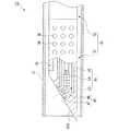
図3に示すように、穿刺針3は、処置具挿入口16aまで延びる長尺で可撓性を有する円筒形状のシース31と、このシース31の内部に進退・回転自在に挿通され可撓性を有する挿入部32を有している。
挿入部32は、先端に鋭利な刃面33Aを有する硬質の先端部33と、先端部33の後端から穿刺針3を挿入する処置具挿入口16aまでつながる長尺の可撓部34とを備えている。
また、穿刺針3の基端側にはシース31に対して先端部33の突出量を制御する操作部35が設けられており、先端部33の可撓部34側の周面には、超音波振動子部21から発信される超音波を反射しやすいように円形の凹部であるディンプル36が施されている。As shown in FIG. 3, the puncture needle 3 has a long and flexible
The
In addition, an
先端部33の内部には、刃面33Aから被検体を観察するための光学的観察手段41と、光学的観察手段41による観察部位に照明光を照射する照明手段42とが設けられている。
光学的観察手段41は、照明手段42により照明された照明範囲内の対象物の光学像を結像させるレンズ部43と、結像位置に配置され結像された光学像を電気信号に変換するCCD(固体撮像素子)44と、CCD44によって電気信号に変換された光学画像データを高倍率画像処理装置7に伝送するためのイメージガイドケーブル45とを備えている。
また、照明手段42は、光ファイバで形成され高倍率観察光源装置8で生じた照明光を先端部33まで導光するライトガイド46と、ライトガイド46の先端面に配されてレンズ部43の周囲に設けられた照明レンズ47とを備えている。An optical observation means 41 for observing the subject from the
The
The illumination means 42 is formed of an optical fiber and guides the illumination light generated by the high-magnification observation
上記の構成からなる穿刺針3及び内視鏡観察装置1を用いた被検体A1の観察方法について図4及び図5を参照しながら説明する。
先ず、超音波内視鏡2を体腔内に挿入し、内視鏡観察手段23により体腔内の観察を行って被検体A1を確認する。
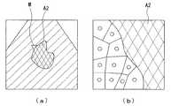
次に、図4(a)に示すように、超音波振動子部21を穿刺針3で穿刺する被検体A1の近傍に接触させて被検体A1に向けて超音波を発信することで、図5(a)に示すような病変部位A2が確認された超音波観察像を得ることにより、穿刺部位を確認する(後述するマーカMはこのとき表示されない。)。
そして、図4(b)に示すように、チャンネル16に穿刺針3を挿通させ、超音波観察像により穿刺部位を確認しながら先端部33をシース31から突出させて被検体A1に穿刺させる。
このとき、先端開口22から突出した穿刺針3は、ディンプル36により超音波が効率よく反射されるため、超音波振動子部21による超音波観察像に穿刺針3が描出されることで病変部位A2への確実な穿刺が行われる。An observation method of the subject A1 using the puncture needle 3 and the endoscope observation apparatus 1 having the above-described configuration will be described with reference to FIGS.
First, the
Next, as shown in FIG. 4A, the
Then, as shown in FIG. 4B, the puncture needle 3 is inserted into the
At this time, since the puncture needle 3 protruding from the
穿刺針3の光学的観察手段41による被検体A1の高倍率観察像は、CCD44によって電気信号に変換されイメージガイドケーブル45を介して高倍率画像処理装置7に伝送され、図5(b)に示すような高倍率観察像として表示装置10に表示される。
また、超音波振動子部21による超音波観察像及び光学的観察手段41による被検体A1の高倍率観察像は、超音波観察像内に検出された穿刺針3の位置情報と共に記録装置9に記録される。なお、穿刺針3の位置情報は、超音波信号の強弱により超音波観測装置4が自動的に判断する方法や、超音波画像上の位置を使用者がマーカなどで設定するといった方法がある。A high-magnification observation image of the subject A1 by the optical observation means 41 of the puncture needle 3 is converted into an electrical signal by the
Further, the ultrasonic observation image by the
超音波内視鏡2を体腔内に挿入しての観察の終了後、得られた観察像を確認したいときは、記録装置9に記録された超音波観察像を図5(a)に示すように表示装置10に表示させることができる。このとき、超音波画像と共にマーカMが表示され、超音波画像中で穿刺針3による高倍率観察像を得た任意箇所をマーカMで選択することにより、選択箇所に対応した高倍率観察像が図5(b)に示すように表示される。
このようにして超音波観察像と高倍率観察像とを対応表示させて画像表示させることができ、超音波観察像及び高倍率観察像により被検体A1の診断を行うことができる。When it is desired to check the obtained observation image after the observation with the
In this way, the ultrasonic observation image and the high-magnification observation image can be displayed in correspondence with each other, and the subject A1 can be diagnosed using the ultrasonic observation image and the high-magnification observation image.
このように、本実施形態に係る穿刺針3及び超音波内視鏡システム1は、穿刺針3の先端側に光学的観察手段41が設けられているため、生体組織の採取が行えなくても生体組織の検査診断ができ、診断精度の向上が図れる。
また、穿刺針3による光学観察像を得た任意箇所を超音波画像中で選択することで、超音波観察像と高倍率観察像とを対応させて表示装置10に表示させることができる。したがって、体腔内に超音波内視鏡2を挿入させての観察を行った後で生体組織の検査診断が容易にでき、診断精度の向上が図れる。As described above, the puncture needle 3 and the ultrasonic endoscope system 1 according to the present embodiment are provided with the optical observation means 41 on the distal end side of the puncture needle 3, so that it is not possible to collect a living tissue. Examination and diagnosis of living tissue can be performed, and diagnostic accuracy can be improved.
In addition, by selecting an arbitrary position from which an optical observation image is obtained by the puncture needle 3 in the ultrasonic image, the ultrasonic observation image and the high-magnification observation image can be displayed in correspondence with each other on the
なお、上記第1の実施形態では、光学的観察手段41が穿刺針3の刃面33Aに向けて配置されたが、図6に示すように側面に向けて配置されてもよい。これは、半径方向外方を観察可能とするように光学的観察手段41及び照明手段42を側面に向けて配置させている。 In the first embodiment, the optical observation means 41 is disposed toward the
次に、第2の実施形態について図7を参照しながら説明する。なお、図7は本実施形態における穿刺針の先端部を示す断面図である。また、ここで説明する実施形態はその基本的構成が上述した第1の実施形態と同様であり、上述の第1の実施形態に別の要素を付加したものである。したがって、図7においては、図3と同一構成要素に同一符号をし、この説明を省略する。 Next, a second embodiment will be described with reference to FIG. FIG. 7 is a cross-sectional view showing the distal end portion of the puncture needle in the present embodiment. In addition, the basic configuration of the embodiment described here is the same as that of the first embodiment described above, and another element is added to the first embodiment described above. Therefore, in FIG. 7, the same components as those in FIG.
第2の実施形態と第1の実施形態との異なる点は、第1の実施形態における穿刺針3では中実型穿刺針であるのに対して、第2の実施形態における穿刺針50では、図7に示されるように、挿入部32に軸方向の貫通孔51が設けられた針管とされている点である。
この貫通孔51は、刃面33Aから操作部35まで設けられており、操作部35から貫通孔52に対して陰圧を掛けることが可能となっている。The difference between the second embodiment and the first embodiment is that the puncture needle 3 in the first embodiment is a solid puncture needle, whereas the
The through
この穿刺針50は、貫通孔51が設けられているため、被検体の観察後、穿刺針50の基端側から陰圧を掛けることにより生体組織の採取が行える。このとき、光学的観察手段41によって生体組織が壊死した組織か、病変組織かを確認してから生体組織の採取を行うことができるので診断精度の向上が図れる。また、貫通孔51からの染色液や薬液を注入するなどの処置も可能となる。 Since the
なお、上記第2の実施形態においても、上述した第1の実施形態と同様に光学的観察手段41が穿刺針50の側面に向けて配置されてもよい。 In the second embodiment, the optical observation means 41 may be arranged toward the side surface of the
次に、第3の実施形態について図8を参照しながら説明する。なお、図8は本実施形態における穿刺針の先端部を示す断面図である。また、ここで説明する実施形態はその基本的構成が上述した第2の実施形態と同様であり、上述の第2の実施形態に別の要素を付加したものである。したがって、図8においては、図7と同一構成要素に同一符号をし、この説明を省略する。 Next, a third embodiment will be described with reference to FIG. In addition, FIG. 8 is sectional drawing which shows the front-end | tip part of the puncture needle in this embodiment. Further, the basic configuration of the embodiment described here is the same as that of the second embodiment described above, and another element is added to the second embodiment described above. Therefore, in FIG. 8, the same components as those in FIG.
第3の実施形態と第2の実施形態との異なる点は、第2の実施形態における穿刺針50では針管に光学的観察手段41が設けられているのに対して、第3の実施形態における穿刺針60では、図8に示されるように、挿入部32に設けられた貫通孔61に挿入自在とされた円柱形状を有する線材のスタイレット62を有し、スタイレット62の先端側の内部に光学的観察手段41が設けられている点である。 The difference between the third embodiment and the second embodiment is that in the
この貫通孔61は、上述と同様に、刃面33Aから操作部35まで設けられており、操作部35から貫通孔52に対して陰圧を掛けることが可能となっている。
また、スタイレット62の先端側の内部には、照明手段42により照明された照明範囲内の対象物の光学像を結像させるレンズ部43と、結像位置に配置され結像された光学像を電気信号に変換するCCD44と、CCD44によって電気信号に変換された光学画像データを高倍率画像処理装置7に伝送するためのイメージガイドケーブル45とが設けられている。
また、照明手段42は、レンズ部43の周囲に設けられており、光ファイバで形成され高倍率観察光源装置8で生じた照明光を先端部33まで導光するライトガイド46と、ライトガイド46の先端面に配されている照明レンズ47とを備えている。Similar to the above, the through
Further, inside the distal end side of the
The illumination means 42 is provided around the
この穿刺針60は、光学的観察手段41が設けられているスタイレット62を用いることで上述した他の実施形態と同様の光学的観察を行うことができる。また、貫通孔61中の不要物を除去できる。また、貫通孔61で進退可能であるため、貫通孔61から適宜突出させることにより穿刺針60による穿刺前に被検体の光学的観察が可能であると共に、スタイレット62を抜去すれば通常の穿刺針と同じように検体を採取することが可能となる。 This
なお、本発明の技術範囲は上記実施の形態に限定されるものではなく、本発明の趣旨を逸脱しない範囲において種々の変更を加えることが可能である。
例えば上記実施形態では、超音波振動子部は、圧電素子をアレイ状に複数配列した電子走査方式としているが、これに限らず、超音波振動子部は超音波の送受信方向を機械的に変えるメカニカル走査振動子などであってもよい。
また、超音波内視鏡のガイド下による穿刺に加えて、CT(コンピュータ断層撮影装置)やMRI(核磁気共鳴影像法)などのガイド下による穿刺であってもよく、経皮的超音波装置のガイド下による体表からの穿刺であってもよい。The technical scope of the present invention is not limited to the above embodiment, and various modifications can be made without departing from the spirit of the present invention.
For example, in the above-described embodiment, the ultrasonic transducer unit uses an electronic scanning method in which a plurality of piezoelectric elements are arranged in an array. However, the present invention is not limited to this, and the ultrasonic transducer unit mechanically changes the transmission / reception direction of ultrasonic waves. A mechanical scanning vibrator or the like may be used.
In addition to puncture under the guidance of an ultrasonic endoscope, puncture under the guidance of CT (Computer Tomography) or MRI (Nuclear Magnetic Resonance Imaging) may be used. It may be a puncture from the body surface under the guide.
1 超音波内視鏡システム
2 超音波内視鏡(内視鏡)
3、50、60 穿刺針
22 先端開口
33A 刃面
41 光学的観察手段
43 レンズ部
44 CCD(固体撮像素子)
45 イメージガイドケーブル
51、61 貫通孔
62 スタイレット1
3, 50, 60
45
Claims (4)
Translated fromJapanese前記スタイレットの先端側に先端外方を観察する光学的観察手段が設けられていることを特徴とする穿刺針。In a puncture needle having a needle tube having a blade surface on the distal end side punctured by a subject, a through hole provided in the axial direction, and a stylet that can be inserted into the needle tube,
A puncture needle characterized in that an optical observation means for observing the outside of the tip is provided on the tip side of the stylet.
前記超音波振動子の走査結果を超音波観察像として表示可能に処理する超音波観測装置
と、該超音波観察像を表示する表示装置と、前記チャンネルに挿通可能である請求項1又は2に記載の穿刺針からなり、
前記穿刺針の先端側を前記チャンネルの先端開口から突出されると前記表示装置に表示された超音波画像上に穿刺針が判別可能に表示されることを特徴とする超音波内視鏡システム。An ultrasonic transducer unit that scans the distal end to the outside; an ultrasonic endoscope that has a channel that leads to the distal end side; and a distal end opening of the channel is arranged toward the scanning range of the ultrasonic transducer; and
Wherein the ultrasound observation apparatus that processes can be displayed scanning results of the ultrasonic vibrator as the ultrasonic observation image, a display device for displaying the ultrasound observation image, toclaim 1 or 2 can be inserted into the channel It consists of the puncture needle described,
An ultrasonicendoscope system , wherein a puncture needle is displayed in an distinguishable manner on an ultrasonic image displayed on the display device when a distal end side of the puncture needle is projected from a distal end opening of the channel.
前記超音波観察像及び前記高倍率観察像を表示させる表示装置と、
前記光学的観察手段で観察を行った任意箇所を前記超音波観察像中で選択することにより、選択箇所の前記光学的観察手段による高倍率観察像を前記表示装置に表示させる画像処理装置とを備えていることを特徴とする請求項3に記載の超音波内視鏡システム。A recording apparatus for recording an ultrasonic observation image by the ultrasonic transducer unit and a high-magnification observation image by the optical observation unit;
A display device for displaying the ultrasonic observation image and the high-magnification observation image;
An image processing device for displaying on the display device a high-magnification observation image by the optical observation means at the selected location by selecting an arbitrary location observed by the optical observation means in the ultrasonic observation image. The ultrasonic endoscope system according toclaim 3 , further comprising:
Priority Applications (1)
| Application Number | Priority Date | Filing Date | Title |
|---|---|---|---|
| JP2003354029AJP4533615B2 (en) | 2003-10-14 | 2003-10-14 | Puncture needle and ultrasonic endoscope system |
Applications Claiming Priority (1)
| Application Number | Priority Date | Filing Date | Title |
|---|---|---|---|
| JP2003354029AJP4533615B2 (en) | 2003-10-14 | 2003-10-14 | Puncture needle and ultrasonic endoscope system |
Publications (2)
| Publication Number | Publication Date |
|---|---|
| JP2005118134A JP2005118134A (en) | 2005-05-12 |
| JP4533615B2true JP4533615B2 (en) | 2010-09-01 |
Family
ID=34612132
Family Applications (1)
| Application Number | Title | Priority Date | Filing Date |
|---|---|---|---|
| JP2003354029AExpired - Fee RelatedJP4533615B2 (en) | 2003-10-14 | 2003-10-14 | Puncture needle and ultrasonic endoscope system |
Country Status (1)
| Country | Link |
|---|---|
| JP (1) | JP4533615B2 (en) |
Cited By (1)
| Publication number | Priority date | Publication date | Assignee | Title |
|---|---|---|---|---|
| WO2019056784A1 (en)* | 2017-09-20 | 2019-03-28 | 史军 | Medical device having visible puncture apparatus |
Families Citing this family (18)
| Publication number | Priority date | Publication date | Assignee | Title |
|---|---|---|---|---|
| JP4750484B2 (en)* | 2005-06-30 | 2011-08-17 | 新コスモス電機株式会社 | Gas detector |
| JP4996141B2 (en)* | 2006-06-12 | 2012-08-08 | 日立アロカメディカル株式会社 | Ultrasonic diagnostic equipment |
| WO2009109873A1 (en) | 2008-03-03 | 2009-09-11 | Koninklijke Philips Electronics N.V. | Biopsy guidance by image-based x-ray guidance system and photonic needle |
| WO2009109879A2 (en)* | 2008-03-03 | 2009-09-11 | Koninklijke Philips Electronics N.V. | Biopsy guidance by electromagnetic tracking and photonic needle |
| US20100063401A1 (en)* | 2008-09-09 | 2010-03-11 | Olympus Medical Systems Corp. | Ultrasound endoscope system and ultrasound observation method |
| US8206315B2 (en)* | 2008-09-30 | 2012-06-26 | Suros Surgical Systems, Inc. | Real-time pathology |
| JP5388619B2 (en)* | 2009-02-16 | 2014-01-15 | Hoya株式会社 | Ultrasound endoscope puncture needle and manufacturing method thereof |
| JP5575534B2 (en)* | 2010-04-30 | 2014-08-20 | 株式会社東芝 | Ultrasonic diagnostic equipment |
| EP2599427A4 (en)* | 2010-07-28 | 2017-07-05 | Olympus Corporation | Rigid scope |
| JP2015016300A (en)* | 2013-06-13 | 2015-01-29 | キヤノン株式会社 | Biopsy support apparatus and biopsy support method |
| EP3102113B1 (en) | 2014-02-03 | 2019-08-07 | The University Of Western Australia | A medical device for insertion into a material to obtain a material sample |
| JP6284464B2 (en)* | 2014-09-26 | 2018-02-28 | オリンパス株式会社 | Endoscopic puncture needle |
| CN110051386A (en)* | 2019-05-30 | 2019-07-26 | 苏州希声科技有限公司 | A kind of Real-time High Resolution guiding puncture system |
| WO2021019851A1 (en)* | 2019-07-26 | 2021-02-04 | 富士フイルム株式会社 | Measurement device, ultrasonic diagnostic device, measurement method, measurement program |
| AU2022200563B2 (en)* | 2021-02-03 | 2023-03-23 | Chin Piao Chang | Endoscope assembly and endoscope system having the same |
| EP4039166A1 (en)* | 2021-02-03 | 2022-08-10 | Hong So Kao | Endoscope assembly having a surgical instrument and endoscope system having the same |
| CN113317850B (en)* | 2021-05-14 | 2023-01-13 | 上海埃尔顿医疗器械有限公司 | Ultrasonic biopsy needle |
| WO2025094900A1 (en)* | 2023-10-31 | 2025-05-08 | エア・ウォーター株式会社 | Lens assembly for image transmission, rigid endoscope, and image transmission system |
Family Cites Families (7)
| Publication number | Priority date | Publication date | Assignee | Title |
|---|---|---|---|---|
| JPH0626312B2 (en)* | 1985-07-02 | 1994-04-06 | 松下電器産業株式会社 | Multi-input CMOS gate circuit |
| JPH0754855Y2 (en)* | 1989-06-16 | 1995-12-18 | アロカ株式会社 | Photoacoustic sensor |
| JPH04131746A (en)* | 1990-09-21 | 1992-05-06 | Olympus Optical Co Ltd | Laser diagnostic device |
| JPH1147139A (en)* | 1997-07-30 | 1999-02-23 | Shimadzu Corp | Surgical equipment |
| JP2001149305A (en)* | 1999-11-29 | 2001-06-05 | Olympus Optical Co Ltd | Optical scanning probe device |
| JP2002345820A (en)* | 2001-05-28 | 2002-12-03 | Asahi Optical Co Ltd | Ultrasound endoscope tip |
| US7527590B2 (en)* | 2002-03-19 | 2009-05-05 | Olympus Corporation | Anastomosis system |
- 2003
- 2003-10-14JPJP2003354029Apatent/JP4533615B2/ennot_activeExpired - Fee Related
Cited By (5)
| Publication number | Priority date | Publication date | Assignee | Title |
|---|---|---|---|---|
| WO2019056784A1 (en)* | 2017-09-20 | 2019-03-28 | 史军 | Medical device having visible puncture apparatus |
| JP2020534133A (en)* | 2017-09-20 | 2020-11-26 | 藍綫▲はく▼立医療科技(上海)有限公司 | Medical device with visual puncture device |
| JP2022130442A (en)* | 2017-09-20 | 2022-09-06 | 藍綫▲はく▼立医療科技(上海)有限公司 | Medical device having visible puncture apparatus |
| JP7526973B2 (en) | 2017-09-20 | 2024-08-02 | 藍綫▲はく▼立医療科技(上海)有限公司 | Medical device with visual puncture device |
| US12414799B2 (en) | 2017-09-20 | 2025-09-16 | Jun Shi | Medical device having visual puncture apparatus |
Also Published As
| Publication number | Publication date |
|---|---|
| JP2005118134A (en) | 2005-05-12 |
Similar Documents
| Publication | Publication Date | Title |
|---|---|---|
| JP4533615B2 (en) | Puncture needle and ultrasonic endoscope system | |
| JP5153476B2 (en) | Endoscope device | |
| CN102131467B (en) | Ultrasonic endoscope system, ultrasonic probe, and ultrasonic endoscope | |
| JP3594278B2 (en) | Intracavity ultrasonic probe device | |
| JP5650544B2 (en) | Apparatus and method for microelastography | |
| JPH04500619A (en) | Medical detection method and device using fiber bundles for remote optical transmission | |
| JP2006006958A (en) | Medical micro-ultrasonic-OCT probe via endoscope | |
| KR20070061466A (en) | Ultrasound Probe and Ultrasound Diagnostic Device | |
| JP2011522654A (en) | Biopsy device with acoustic elements | |
| EP2070480A1 (en) | Ultrasonic image processing device, and ultrasonic diagnosing device | |
| JP5437512B2 (en) | Sample collection treatment tool | |
| US20140100457A1 (en) | Treatment instrument for endoscope | |
| JP5226908B1 (en) | Biopsy instrument | |
| JP2017213348A (en) | Probe adapter, ultrasonic probe and ultrasonic diagnostic apparatus | |
| JP2010274123A (en) | Puncturing needle for endoscope | |
| WO2006028249A1 (en) | Ultrasonic probe, ultrasonograph, and ultrasonography | |
| JP2014124452A (en) | Medicine injection system | |
| JP2005118133A (en) | Ultrasonic endoscope, observation probe, and endoscopic observation apparatus | |
| JP5006591B2 (en) | Ultrasound endoscope | |
| JP4499488B2 (en) | Endoscopic puncture needle | |
| JP4119530B2 (en) | Endoscope device and position detection catheter inserted into endoscope | |
| JP4248615B2 (en) | Ultrasound diagnostic imaging equipment | |
| CN102068285A (en) | Esophagoscope system with color Doppler ultrasound scanning function | |
| JPH07194594A (en) | Instrument insertion passage for in-vivo inspection device | |
| JP3671764B2 (en) | Endoscope removable electronic scanning ultrasonic inspection system |
Legal Events
| Date | Code | Title | Description |
|---|---|---|---|
| A621 | Written request for application examination | Free format text:JAPANESE INTERMEDIATE CODE: A621 Effective date:20060824 | |
| A131 | Notification of reasons for refusal | Free format text:JAPANESE INTERMEDIATE CODE: A131 Effective date:20090616 | |
| A521 | Request for written amendment filed | Free format text:JAPANESE INTERMEDIATE CODE: A523 Effective date:20090805 | |
| A521 | Request for written amendment filed | Free format text:JAPANESE INTERMEDIATE CODE: A821 Effective date:20090806 | |
| A131 | Notification of reasons for refusal | Free format text:JAPANESE INTERMEDIATE CODE: A131 Effective date:20100202 | |
| A521 | Request for written amendment filed | Free format text:JAPANESE INTERMEDIATE CODE: A523 Effective date:20100311 | |
| A521 | Request for written amendment filed | Free format text:JAPANESE INTERMEDIATE CODE: A821 Effective date:20100312 | |
| TRDD | Decision of grant or rejection written | ||
| A01 | Written decision to grant a patent or to grant a registration (utility model) | Free format text:JAPANESE INTERMEDIATE CODE: A01 Effective date:20100608 | |
| A01 | Written decision to grant a patent or to grant a registration (utility model) | Free format text:JAPANESE INTERMEDIATE CODE: A01 | |
| A61 | First payment of annual fees (during grant procedure) | Free format text:JAPANESE INTERMEDIATE CODE: A61 Effective date:20100614 | |
| R151 | Written notification of patent or utility model registration | Ref document number:4533615 Country of ref document:JP Free format text:JAPANESE INTERMEDIATE CODE: R151 | |
| FPAY | Renewal fee payment (event date is renewal date of database) | Free format text:PAYMENT UNTIL: 20130618 Year of fee payment:3 | |
| S531 | Written request for registration of change of domicile | Free format text:JAPANESE INTERMEDIATE CODE: R313531 | |
| R350 | Written notification of registration of transfer | Free format text:JAPANESE INTERMEDIATE CODE: R350 | |
| R250 | Receipt of annual fees | Free format text:JAPANESE INTERMEDIATE CODE: R250 | |
| R250 | Receipt of annual fees | Free format text:JAPANESE INTERMEDIATE CODE: R250 | |
| R250 | Receipt of annual fees | Free format text:JAPANESE INTERMEDIATE CODE: R250 | |
| LAPS | Cancellation because of no payment of annual fees |