JP4533143B2 - Disposable syringe and plunger rod locking device for the syringe - Google Patents
Disposable syringe and plunger rod locking device for the syringeDownload PDFInfo
- Publication number
- JP4533143B2 JP4533143B2JP2004540143AJP2004540143AJP4533143B2JP 4533143 B2JP4533143 B2JP 4533143B2JP 2004540143 AJP2004540143 AJP 2004540143AJP 2004540143 AJP2004540143 AJP 2004540143AJP 4533143 B2JP4533143 B2JP 4533143B2
- Authority
- JP
- Japan
- Prior art keywords
- locking element
- syringe
- plunger rod
- body portion
- stopper
- Prior art date
- Legal status (The legal status is an assumption and is not a legal conclusion. Google has not performed a legal analysis and makes no representation as to the accuracy of the status listed.)
- Expired - Lifetime
Links
Images


Classifications
- A—HUMAN NECESSITIES
- A61—MEDICAL OR VETERINARY SCIENCE; HYGIENE
- A61M—DEVICES FOR INTRODUCING MEDIA INTO, OR ONTO, THE BODY; DEVICES FOR TRANSDUCING BODY MEDIA OR FOR TAKING MEDIA FROM THE BODY; DEVICES FOR PRODUCING OR ENDING SLEEP OR STUPOR
- A61M5/00—Devices for bringing media into the body in a subcutaneous, intra-vascular or intramuscular way; Accessories therefor, e.g. filling or cleaning devices, arm-rests
- A61M5/50—Devices for bringing media into the body in a subcutaneous, intra-vascular or intramuscular way; Accessories therefor, e.g. filling or cleaning devices, arm-rests having means for preventing re-use, or for indicating if defective, used, tampered with or unsterile
- A61M5/508—Means for preventing re-use by disrupting the piston seal, e.g. by puncturing
- A—HUMAN NECESSITIES
- A61—MEDICAL OR VETERINARY SCIENCE; HYGIENE
- A61M—DEVICES FOR INTRODUCING MEDIA INTO, OR ONTO, THE BODY; DEVICES FOR TRANSDUCING BODY MEDIA OR FOR TAKING MEDIA FROM THE BODY; DEVICES FOR PRODUCING OR ENDING SLEEP OR STUPOR
- A61M5/00—Devices for bringing media into the body in a subcutaneous, intra-vascular or intramuscular way; Accessories therefor, e.g. filling or cleaning devices, arm-rests
- A61M5/50—Devices for bringing media into the body in a subcutaneous, intra-vascular or intramuscular way; Accessories therefor, e.g. filling or cleaning devices, arm-rests having means for preventing re-use, or for indicating if defective, used, tampered with or unsterile
- A61M5/5013—Means for blocking the piston or the fluid passageway to prevent illegal refilling of a syringe
- A—HUMAN NECESSITIES
- A61—MEDICAL OR VETERINARY SCIENCE; HYGIENE
- A61M—DEVICES FOR INTRODUCING MEDIA INTO, OR ONTO, THE BODY; DEVICES FOR TRANSDUCING BODY MEDIA OR FOR TAKING MEDIA FROM THE BODY; DEVICES FOR PRODUCING OR ENDING SLEEP OR STUPOR
- A61M5/00—Devices for bringing media into the body in a subcutaneous, intra-vascular or intramuscular way; Accessories therefor, e.g. filling or cleaning devices, arm-rests
- A61M5/178—Syringes
- A61M5/31—Details
- A61M5/315—Pistons; Piston-rods; Guiding, blocking or restricting the movement of the rod or piston; Appliances on the rod for facilitating dosing ; Dosing mechanisms
- A61M5/31511—Piston or piston-rod constructions, e.g. connection of piston with piston-rod
- A61M2005/31516—Piston or piston-rod constructions, e.g. connection of piston with piston-rod reducing dead-space in the syringe barrel after delivery
- A—HUMAN NECESSITIES
- A61—MEDICAL OR VETERINARY SCIENCE; HYGIENE
- A61M—DEVICES FOR INTRODUCING MEDIA INTO, OR ONTO, THE BODY; DEVICES FOR TRANSDUCING BODY MEDIA OR FOR TAKING MEDIA FROM THE BODY; DEVICES FOR PRODUCING OR ENDING SLEEP OR STUPOR
- A61M5/00—Devices for bringing media into the body in a subcutaneous, intra-vascular or intramuscular way; Accessories therefor, e.g. filling or cleaning devices, arm-rests
- A61M5/50—Devices for bringing media into the body in a subcutaneous, intra-vascular or intramuscular way; Accessories therefor, e.g. filling or cleaning devices, arm-rests having means for preventing re-use, or for indicating if defective, used, tampered with or unsterile
- A61M5/5013—Means for blocking the piston or the fluid passageway to prevent illegal refilling of a syringe
- A61M5/502—Means for blocking the piston or the fluid passageway to prevent illegal refilling of a syringe for blocking the piston
- A61M2005/5033—Means for blocking the piston or the fluid passageway to prevent illegal refilling of a syringe for blocking the piston by use of an intermediate blocking member positioned between the syringe barrel and the piston rod to prevent retraction of the latter, e.g. toothed clip placed on the piston rod
- A—HUMAN NECESSITIES
- A61—MEDICAL OR VETERINARY SCIENCE; HYGIENE
- A61M—DEVICES FOR INTRODUCING MEDIA INTO, OR ONTO, THE BODY; DEVICES FOR TRANSDUCING BODY MEDIA OR FOR TAKING MEDIA FROM THE BODY; DEVICES FOR PRODUCING OR ENDING SLEEP OR STUPOR
- A61M5/00—Devices for bringing media into the body in a subcutaneous, intra-vascular or intramuscular way; Accessories therefor, e.g. filling or cleaning devices, arm-rests
- A61M5/50—Devices for bringing media into the body in a subcutaneous, intra-vascular or intramuscular way; Accessories therefor, e.g. filling or cleaning devices, arm-rests having means for preventing re-use, or for indicating if defective, used, tampered with or unsterile
- A61M5/5013—Means for blocking the piston or the fluid passageway to prevent illegal refilling of a syringe
- A61M5/502—Means for blocking the piston or the fluid passageway to prevent illegal refilling of a syringe for blocking the piston
Landscapes
- Health & Medical Sciences (AREA)
- Vascular Medicine (AREA)
- Engineering & Computer Science (AREA)
- Anesthesiology (AREA)
- Biomedical Technology (AREA)
- Heart & Thoracic Surgery (AREA)
- Hematology (AREA)
- Life Sciences & Earth Sciences (AREA)
- Animal Behavior & Ethology (AREA)
- General Health & Medical Sciences (AREA)
- Public Health (AREA)
- Veterinary Medicine (AREA)
- Infusion, Injection, And Reservoir Apparatuses (AREA)
- Fluid-Damping Devices (AREA)
Abstract
Description
Translated fromJapanese本発明は、使い捨て注射器および該注射器のプランジャアセンブリをロックするためのロック装置に関するものである。 The present invention relates to a disposable syringe and a locking device for locking a plunger assembly of the syringe.
アメリカ合衆国や世界中では、1回のみの使用が意図されている皮下注射器製品を複数回使用することが、薬物の乱用や、特に疾病感染の媒介となっている。注射器を日常的に共有したり、再使用する静注薬物の使用者は、エイズ・ウイルスに対し高い危険性にさらされている集団である。また、再使用の影響は、注射器製品を繰り返して使用する発展途上国においては、多くの病気が蔓延する原因となり得るので、大きな懸念事項である。 In the United States and around the world, multiple use of hypodermic syringe products that are intended for one-time use has become a mediator of drug abuse and especially disease infection. Intravenous drug users who share and reuse syringes on a daily basis are a group at high risk for AIDS virus. Also, the effects of reuse are a major concern in developing countries where repeated use of syringe products can cause many diseases to spread.
多くの注射器はこの問題を改善するように作製することができる。これらのいくつかは、破壊装置を使用するか、またはもろい部分を注射器に組み込んでおくことによって使用後に注射器を破壊する特定の動作を要し、力が加えられることにより注射器が使用不能になるようにするものである。他のものは、注射器使用者の意識的な行為によって、注射器機能の破壊または無効化を許容する構造を含んでいる。これらの装置の多くはよく機能しているが、それらは実際の行為で注射器を破壊または使用不能にするという使用者の特定の意思を必要とする。注射器を再使用する特定の意図を持っている使用者には、これらの装置はいずれも効果がない。 Many syringes can be made to ameliorate this problem. Some of these require a specific action to break the syringe after use, either by using a breaking device or by incorporating a fragile part into the syringe, so that force is applied to render the syringe unusable It is to make. Others include structures that allow the syringe function to be destroyed or disabled by conscious action of the syringe user. Many of these devices function well, but they require the user's specific intention to break or disable the syringe in practice. None of these devices are effective for users who have a specific intent to reuse the syringe.
使用者側の一切の追加行為なしで、さらなる使用が自動的に不能になる使い捨て皮下注射器が必要である。そのような注射器の1つが特許文献1に開示されている。この特許文献1に開示された注射器には、注射器外筒に設けられたロックエレメントが含まれている。そのロックエレメントは、注射器外筒の内面と係合し、近位端側で外側に向く棘(barb)と、内側に向く駆動エッジとを含み、駆動エッジは、ストッパが前進するときにプランジャロッドと相互作用してロックエレメントを外筒に沿って移動させるのに適したものとなっている。プランジャロッドは棚部を含み、この棚はロックエレメントのおおよその長さである支持壁の基端側からの距離に位置している。ロックエレメントの駆動エッジは棚部と係合し、これによりロックエレメントがプランジャロッドおよびストッパと共に確実に端部へ移動する。同様のロックエレメントを含む注射器は特許文献2にも開示されている。 There is a need for a disposable hypodermic syringe that automatically disables further use without any additional action on the part of the user. One such syringe is disclosed in US Pat. The syringe disclosed in Patent Document 1 includes a lock element provided on a syringe outer cylinder. The locking element engages the inner surface of the syringe barrel and includes a barb facing outward on the proximal end side and a driving edge facing inward, the driving edge being a plunger rod when the stopper is advanced Is suitable for moving the locking element along the outer cylinder. The plunger rod includes a shelf that is located at a distance from the proximal side of the support wall, which is the approximate length of the locking element. The drive edge of the locking element engages the shelf, which ensures that the locking element moves with the plunger rod and stopper to the end. A syringe including a similar locking element is also disclosed in US Pat.
特許文献3から特許文献5には、歯またはねじ山(ridge)を有するプランジャロッドと、歯またはねじ山と係合するロックエレメントとを持つ使い捨て注射器が開示されている。また、これらの注射器のロック部材も外方に延在する歯または突起物を含み、これらの歯または突起物は注射器外筒の内側表面と係合する。それらの注射器のプランジャロッドは、注射器外筒の中へ流体を引き込むために後退可能である一方、ロックエレメントは静止したままである。プランジャロッドが末端側に移動することによって流体が吐出され、ロック部材がプランジャロッドとともに末端側に移動することで更なるプランジャロッドの後退が阻止されるようになる。 U.S. Pat. Nos. 5,098,086 and 5,037,037 disclose disposable syringes having plunger rods having teeth or ridges and locking elements that engage the teeth or threads. These syringe locking members also include outwardly extending teeth or protrusions that engage the inner surface of the syringe barrel. The plunger rods of those syringes can be retracted to draw fluid into the syringe barrel while the locking element remains stationary. When the plunger rod moves to the distal side, the fluid is discharged, and when the lock member moves to the distal side together with the plunger rod, further plunger rod retraction is prevented.
従来技術は再使用防止を助けるために、自動的に注射器外筒およびプランジャロッドをロックするロックエレメントを持っている注射器を提供するものである。しかしながら、薬物注入後にプランジャロッドを後退させる過度の力が用いられる場合に注射器機能の破壊を生じさせる付加的な特徴は依然として必要である。 The prior art provides a syringe having a locking element that automatically locks the syringe barrel and plunger rod to help prevent reuse. However, there is still a need for additional features that cause destruction of the syringe function if excessive force is used to retract the plunger rod after drug injection.
本発明は、ストッパを有する注射器プランジャロッドを注射器外筒に対してロックするため、およびストッパを使用不能にするためのロックエレメントを提供する。ロックエレメントは基端部と末端部とを有する本体部分を含んでいる。第1および第2の手段が本体部分に設けられ、それぞれ、プランジャロッドおよび注射器外筒と係合し、ロックエレメントが注射器外筒に関して末端側には摺動できるが、基端側には摺動できないようになっている。1つ以上のカッタが好ましくは末端部に一体に取り付けられ、過大な力がプランジャロッドにかかった場合に、ストッパを切断するために設けられている。カッタはカッティングエッジによって形成されていても良い。 The present invention provides a locking element for locking a syringe plunger rod having a stopper relative to a syringe barrel and for disabling the stopper. The locking element includes a body portion having a proximal end and a distal end. First and second means are provided on the body portion and engage the plunger rod and syringe barrel, respectively, and the locking element can slide distally with respect to the syringe barrel, but slides proximally I can't do it. One or more cutters are preferably attached integrally to the distal end and are provided to cut the stopper when an excessive force is applied to the plunger rod. The cutter may be formed by a cutting edge.
発明はさらに、注射器外筒に対してプランジャロッドをロックでき、かつストッパを使用不能にできるロックエレメント注射器アセンブリに関連している。このアセンブリは、注射器外筒とプランジャロッドと、ロックエレメントと、カッタとを含んでいる。注射器外筒はチャンバを形成する内側表面と、開放端と、末端とを含んでいる。プランジャロッドアセンブリは細長い本体部分とストッパとを含んでいる。ロックエレメントは、注射器外筒のチャンバ内で摺動可能に配されており、注射器外筒の内側表面と係合し、ロックエレメントは注射器の開放端の方向には実質的に動けないようになっている。またロックエレメントはプランジャロッドアセンブリと係合可能であり、プランジャロッドアセンブリおよびロックエレメントはともに、注射器外筒の末端部に向けて移動可能となっている。好適な実施形態では、プランジャロッドアセンブリは初期にはロックエレメントに対して近接端側に移動可能であり、これによって注射器外筒に流体が吸引される。カッタはロックエレメントに接続されており、ストッパに係合可能である。カッタは、注射器外筒からプランジャロッドアセンブリを引き戻す際にストッパを切断することができる。 The invention further relates to a locking element syringe assembly capable of locking the plunger rod relative to the syringe barrel and disabling the stopper. The assembly includes a syringe barrel, a plunger rod, a locking element, and a cutter. The syringe barrel includes an inner surface forming a chamber, an open end, and a distal end. The plunger rod assembly includes an elongated body portion and a stopper. The locking element is slidably disposed within the chamber of the syringe barrel and engages the inner surface of the syringe barrel so that the locking element is substantially immovable in the direction of the open end of the syringe. ing. The locking element is engageable with the plunger rod assembly, and both the plunger rod assembly and the locking element are movable toward the distal end of the syringe barrel. In a preferred embodiment, the plunger rod assembly is initially movable proximally relative to the locking element, thereby drawing fluid into the syringe barrel. The cutter is connected to the lock element and is engageable with the stopper. The cutter can cut the stopper as the plunger rod assembly is pulled back from the syringe barrel.
ストッパ付きプランジャロッドを具えた、使い捨て注射器のためのロックエレメントの更なる実施形態が提供される。ロックエレメントは、末端部と基端部とを含む。末端部は概してV形状の本体を含み、この本体は長手軸に沿って接続された第1および第2の壁を具えている。第1の脚部が本体の第1の壁から基端側に延在している。第2の脚部が本体の第2の壁から基端側に延在し、間隙によって第1の脚部から分離している。各々の脚部は、一つ以上の棘を含む。切断部材がロックエレメントの末端部上に設けられている。一つ以上の棘がロックエレメントの末端部上に設けられていてもよい。この部分は更に、望ましくは一対の末端側に延在する脚部を含む。棘は、好ましくは末端側に延在する脚部の末端に一体化されている。 A further embodiment of a locking element for a disposable syringe comprising a plunger rod with a stopper is provided. The locking element includes a distal end and a proximal end. The distal end includes a generally V-shaped body that includes first and second walls connected along a longitudinal axis. A first leg extends from the first wall of the main body to the proximal end side. A second leg extends proximally from the second wall of the body and is separated from the first leg by a gap. Each leg includes one or more barbs. A cutting member is provided on the distal end of the locking element. One or more barbs may be provided on the distal end of the locking element. This portion further preferably includes a pair of distally extending legs. The barbs are preferably integrated into the distal ends of the legs that extend distally.
発明による更なる使い捨て注射器アセンブリは、流体を保持するためのチャンバを形成している内側表面を有する外筒を含む。外筒は、開放された基端と、チャンバと連通した通路をもつ末端とを有する。プランジャロッドアッセンブリは外筒と結合して使用するために設けられる。プランジャロッドアセンブリは細長い本体部分を含み、この本体部分は基端と、末端と、この末端近傍で細長い本体部分に取り付けられたストッパとを含んでいる。ストッパは外筒の内側表面と実質的に液密に係合されて摺動可能に配置されている。プランジャロッドアセンブリの細長い本体部分は外筒の開放基端から外方に延在している。それは少なくとも1つの細長い凹部を含んでいる。凹部には、複数の段または歯が設けられている。ロックエレメントは外筒内に配置されている。ロックエレメントからは、基端側を向く1以上の棘が延在している。棘は外筒の内側表面に係合し、ロックエレメントが外筒に対して基端側に移動するのを実質的に阻止している。ロックエレメントもまた、プランジャロッドアセンブリの細長い本体部分と係合し、プランジャロッドアセンブリが前進するときにロックエレメントが外筒の末端に向けて移動できるようにしている。各歯はロックエレメントの基端部に近い端部で係合可能な末端部の表面を定義する。ロックエレメントの末端には切断部材が設けられる。 A further disposable syringe assembly according to the invention includes an outer barrel having an inner surface forming a chamber for holding fluid. The outer cylinder has an open proximal end and a distal end having a passage communicating with the chamber. The plunger rod assembly is provided for use in combination with the outer cylinder. The plunger rod assembly includes an elongated body portion that includes a proximal end, a distal end, and a stopper attached to the elongated body portion near the distal end. The stopper is substantially liquid-tightly engaged with the inner surface of the outer cylinder and is slidably disposed. An elongated body portion of the plunger rod assembly extends outwardly from the open proximal end of the outer cylinder. It includes at least one elongated recess. The recess is provided with a plurality of steps or teeth. The lock element is disposed in the outer cylinder. Extending from the locking element is one or more barbs facing the proximal side. The barbs engage the inner surface of the outer cylinder and substantially prevent the locking element from moving proximally relative to the outer cylinder. The locking element also engages the elongate body portion of the plunger rod assembly so that the locking element can move toward the distal end of the barrel as the plunger rod assembly is advanced. Each tooth defines a distal surface that is engageable at an end near the proximal end of the locking element. A cutting member is provided at the end of the locking element.
流体を保持するためのチャンバを形成する内面を有する外筒と、プランジャロッドアセンブリと、ロックエレメントとを含む使い捨て注射器アセンブリがさらに提供される。プランジャロッドアセンブリは細長い本体部分を含み、これは基端と、末端と、細長い本体部分に取り付けてられているストッパとを有している。ストッパは、外筒の内側表面と液密に係合し、摺動可能に配置されている。ロックエレメントは外筒内に配置されている。それは概ねV形状であり、長手軸に沿って接続される第1および第2の壁を具えている。第1の脚部が第1の壁から基端側に延在し、第2の脚部が第2の壁から基端側に延在している。第第1の棘がロックエレメントの第1の脚部から延在する一方で、第2の棘がロックエレメントの第2の脚部から延在している。一つ以上の棘がロックエレメントの脚部から延在していてもよいことはいうまでもない。各々の脚部は、プランジャロッドアセンブリの本体部分に係合可能な末端部を含む。ロックエレメントは、望ましくはV形状の本体の末端部近くに、基端側を向く棘を含んでいる。そして、望ましくはV形状の本体に一体化された一対の脚部から延在する。ロックエレメントは、したがって、注射器外筒に沿ってプランジャロッドアセンブリとともに末端側に移動可能である。棘は、ロックエレメントが外筒内で基端側に移動するのを実質的に阻止する。V形状の本体の末端には、ストッパを切断するための切断部材が設けられる。 A disposable syringe assembly is further provided that includes an outer cylinder having an inner surface forming a chamber for holding fluid, a plunger rod assembly, and a locking element. The plunger rod assembly includes an elongate body portion having a proximal end, a distal end, and a stopper attached to the elongate body portion. The stopper is fluidly engaged with the inner surface of the outer cylinder and is slidably disposed. The lock element is disposed in the outer cylinder. It is generally V-shaped and comprises first and second walls connected along the longitudinal axis. The first leg extends from the first wall to the proximal side, and the second leg extends from the second wall to the proximal side. A first barb extends from the first leg of the locking element while a second barb extends from the second leg of the locking element. Of course, one or more barbs may extend from the leg of the locking element. Each leg includes a distal end that is engageable with a body portion of the plunger rod assembly. The locking element includes proximally facing barbs, preferably near the distal end of the V-shaped body. And it extends from a pair of leg part desirably integrated with the V-shaped main body. The locking element is thus movable distally with the plunger rod assembly along the syringe barrel. The barbs substantially prevent the locking element from moving proximally within the outer tube. A cutting member for cutting the stopper is provided at the end of the V-shaped main body.
本発明の好適な実施形態を図示し、以下詳細に説明する。本開示は、本発明の理念を例示するためのものとして考慮されるべきであり、例示の実施形態に本発明が限られないことを理解すべきである。 Preferred embodiments of the invention are illustrated and described in detail below. It should be understood that this disclosure is to be considered as illustrative of the spirit of the invention and that the invention is not limited to the illustrated embodiments.
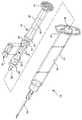
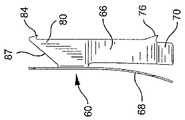
まず図1〜図7を参照するに、注射器アセンブリ20は流体を溜めるためのチャンバ26を形成する内側表面24を有する外筒22を含んでいる。外筒22は開放端28と、チャンバと連通する通路32を有する末端30とを含んでいる。針カニューレ34は外筒の末端部から外方へ突き出している。針カニューレは、通路と流体連通するルーメン(不図示)と、尖鋭な末端とを持つ。この実施形態の注射器アセンブリは、外筒の末端部に着脱可能に取り付けられる針カニューレアセンブリをもつものとして示されている。また、本発明の範囲には、恒久的に固定された針または針/ハブアセンブリを有する注射器外筒、あるいは、固定または着脱可能な尖鋭でないカニューレを有する注射器外筒も含まれる。 Referring first to FIGS. 1-7, the
これまでの段落と以後において、「末端」という用語は、注射器を保持する人から最も離れた端を意味し、一方、「基端部」という用語は注射器を保持する者に最も近い端を意味する。好適な実施形態では、外筒22の基端はフランジ36を含んでおり、注射器アセンブリの取り扱いおよび位置決めを容易にするとともに、薬物充填と投与の間、プランジャロッドに対する外筒の相対位置が維持されるようになっている。 In the previous paragraphs and hereafter, the term “terminal” means the end furthest away from the person holding the syringe, while the term “proximal” means the end closest to the person holding the syringe. To do. In a preferred embodiment, the proximal end of the
注射器アセンブリ20で用いられるプランジャロッドアセンブリ38は、少なくとも1つ望ましくは複数の細長い凹部42を有する細長い本体部分40を含む。細長い本体部分の末端は、一体のストッパ44を含む。ディスク形状のフランジ46がプランジャロッドの基端に設けられ、ユーザが外筒に対してプランジャロッドを動かすのに必要な力を加えることができるようになっている。細長い本体部分40は一対のディスク48、50を末端と基端との中間部に有する。相対的に基端側にあるディスク50とフランジ46との間の部分および2枚のディスク48、50は、細長い凹部42を形成する放射状に延在する壁52を含む。相対的に末端側にあるディスク48に隣接している部分には、一つ以上のラチェット状の歯54を形成する放射状に延在する壁52がある。図8〜図10に示されるように、各々の歯54は末端側に向いた面すなわち肩部56を含む。円錐台状の突起58は、プランジャロッドアセンブリの末端部を形成している。ここに記載され、図示されたプランジャは一体構造であるが、複数の部品により構成されていても良いことは言うまでもない。ストッパは、例えば、プランジャロッドアセンブリ残部を構成している材料とは異なる材料から作られる別体の構成要素であっても良く、可撓性のあるストッパ、Oリングまたはその他のものであってもよい。 The
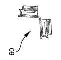
ロックエレメント60は、外筒22内で、かつプランジャロッドアセンブリ38の細長い凹部42内に配される。凹部42は、プランジャロッドアセンブリに対するロックエレメントの長手方向の運動のための経路として働く。 The locking
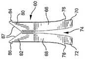
図11〜図15に最もよく示されているように、ロックエレメント60は概ねV形状の本体部分61を含み、この本体部分は長手方向軸に沿って連結された第1および第2の放射状に延在する壁62、64を含んでいる。第1の脚部66が第1の壁から基端側に延在し、第2の脚部68が第2の壁64から基端側に延在している。図14で最もよく示されるように、脚部はV形状の本体部分61に関して外方に広がっている。脚部66、68は、本体部分61の長さより長いほうが望ましい。およそ17ミリメートルの全長を持っているロックエレメントでは、脚部66、68は長さおよそ10ミリメートルであっても良い。 As best shown in FIGS. 11-15, the locking
各々脚部66、68は基端側部分70、72を含み、それぞれはプランジャロッドアセンブリの放射状に伸びている壁52のうちの1枚の方へ曲げられている。それらは、内側縁と外側縁とを更に含む。(ここで使われるように、用語「内側」と「外側」は相対語である。)その内側縁は互いにほぼ隣接しており、長手方向の間隙74によって分離されている。棘76、78は、第1および第2の脚部の外側縁と一体である。棘は基端側を向いており、曲げられた基端側部分70、72から、わずかに末端側に配置されていることが望ましい。棘は、それらが注射器外筒の内部の表面24と係合してロックエレメントの基端側への移動を阻止することができるものである限り、図面に示されるものと異なる外観を有したものでも良い。 Each
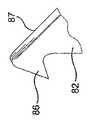
この実施形態では、第2の一対の脚部がV型本体部分61から末端側に延在している。これらの一方の脚部80第1の壁62から延在し、他方の脚部82は第2の壁64から延在している。脚部80および82は、好ましくは、それぞれ、棘84および86を含む。棘84、86は、脚部80、82の末端から基端側に延在している。棘は、末端側に延在している脚部の外側縁上に形成されている。各々の脚部は更に、ストッパ44を貫通可能なカッティングエッジ87を含む。ここで使われるカッティングエッジまたはカッタという用語は、カッティングエッジおよび/または尖鋭な突起、またはその他ストッパを切開または穿孔可能な構造を含むことを意図するものである。 In this embodiment, the second pair of leg portions extends from the V-shaped
ロックエレメントは、ステンレス鋼のような1枚の薄い金属から作られることが望ましい。好適な実施例では、厚みはおよそ0.20mmである。ロックエレメントは、図12で示される平らな状態に予め形成される。点線は、図11および図13〜図15に示されるロックエレメント60をつくるために、平らな基材88に作られる折り目であるところを示す。ロックエレメントの寸法は、それが使われることになっている外筒とプランジャロッドアセンブリに従って選ばれる。この実施形態におけるロックエレメントの2つの半体がなす角度は、望ましくはおよそ90度、好ましくは100度である。プランジャロッドアセンブリ内の凹部42のうちの1つに配置すると、これによりロックエレメントは凹部を形成する2枚の隣接壁52対して力を作用する。好ましくは基材の一側に斜角を設けることによって、少なくとも1つのカッティングエッジが形成される。好適実施形態では、2つのカッティングエッジ87が含まれている。ストッパ44を使用不能とするカッティングエッジを形成するために、基材はその両側を研磨または他の手段によって加工することができる。あるいは、脚部80および/または脚部82上の末端側に延在する棘やその他の切断部材をロックエレメント上に設けて、ストッパを穿孔または切断するようにしてもよい。 The locking element is preferably made from a thin metal such as stainless steel. In the preferred embodiment, the thickness is approximately 0.20 mm. The locking element is preformed in the flat state shown in FIG. The dotted lines indicate where the folds are made in the
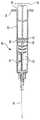
注射器アセンブリは、その構成要素から簡単に造られる。図1で示されるように、ロックエレメント60がプランジャロッドアセンブリの凹部42の1つに置かれるので、脚部66、68の傾けられた端部は相対的に末端側にあるディスク48に隣接している。脚部66、68およびスプリング部材は基端側に延在しており、棘76、78、84、86はプランジャロッドアセンブリに関して基端側に傾いている。そして、プランジャロッド/ロックエレメントアセンブリは外筒22の基端を通して外筒22に挿入される。アセンブリが外筒内を末端側に動かされるとき、棘の傾きによって、外筒の内側表面24と係合しながらの摺動が許容される。ロックエレメントは、ディスク48と脚部66、68の端部との係合によって、プランジャロッドとともに末端側に移動する。ギャップ74は、ロックエレメントの取り付けの後にも、脚部66、68の間で維持される。ギャップを維持することでカンチレバーばねの働きをし、外筒に比較的弱められた力を提供して、使用と取り付けとを容易にする。ストッパが図4で示すように外筒の端壁と係合するまで、図2で示されるように、プランジャロッド/ロックエレメントアセンブリは末端側に動かされる。その結果、使用または保管の準備が整う。針カニューレを保護するために、針カバー90を外筒の末端に取り付けることができる。カバーは使用の前に取り外される。 The syringe assembly is easily constructed from its components. As shown in FIG. 1, because the locking
使用に際しては、プランジャロッドアセンブリ38は、図4で示される位置から図5で示される位置まで後退させられる。これにより、流体が針カニューレ34および通路32を通って外筒22のチャンバ26内に吸い込まれる。かかる後退の間、ロックエレメント60は静止した状態にあり、プランジャロッドアセンブリは外筒22とロックエレメントとの両方に関し、基端側に移動する。これは、外筒の内部の表面24と、棘76、78、84、86との係合による。この好適実施形態においては4つの棘を例示するが、ロックエレメントはより多くの棘をもつ場合でも、または、わずか1つの棘をもつ場合でも機能することができる。棘の数および配置を選択することで、性能を向上することができる。この実施形態では、末端側の棘84および86がカッティングエッジを安定化させて、それがストッパを切るのを補助するものと考えられる。棘は好ましくは外筒より硬い材料から作られ、基端側への移動に抵抗するそれらの能力を強化する。ロックエレメントの脚部66、68の曲げられた端部70、72は、その後退の間、プランジャロッドアセンブリの歯54を乗り越える。複数の歯を設けるのは、ストローク中間でプランジャロッドがリサイクルされるのを防ぐためである。ユーザは、歯を越える脚部の動きを感じ、聞くことができる。 In use, the
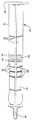
プランジャロッドアセンブリ38の後退は、ロックエレメントによって制限される。図5および図5Aで示すように、ストッパ44の基端側表面は、ロックエレメント60と係合する。ユーザは、この係合を感じることができる。カッティングエッジ87は、通常の使用の間に加えられる力によってはストッパを貫通しない。ロックエレメントは基端側には移動し得ないので、カッティングエッジがストッパを切断することを許容ことによりストッパを破損するような過大な力を加えない限り、プランジャロッドアセンブリをさらに後退させることは不可能である。これは、本発明の重要な特徴である。チャンバ26に引き入れることができる流体の量は、したがって、ロックエレメントの長さと同様にストッパとディスク48の基端側表面との間の距離によって制限される。ストッパと相対的に末端側にあるディスク48との間の距離、およびロックエレメント54の長さは、0.01ml、0.05ml、0.5ml、1.0mlおよび2.0mlの充填量のような特定の用途の必要に応じて選択できることはいうまでもない。 Retraction of the
プランジャロッドアセンブリが図5で示される位置に後退させられるとき、ロックエレメントの脚部66、68の基端部分は、好ましくは最も末端側にある歯54の端部に隣接する。歯54の端部と相対的に末端側にあるディスク48の末端側端面との間の距離は、ロックエレメントの末端部と脚部の基端側部分との間の距離と同じであり、これによってロックエレメントがプランジャロッドアセンブリに関して実質的に移動不能となる。上述したように、ロックエレメントは、外筒22の内側表面と一つ以上の棘との係合によって、外筒内で基端方向に移動不能である。注射器はあらかじめ充填が行われた注射器としてエンドユーザに提供されるものでもよく、その場合には、プランジャロッドアセンブリの後退は不要または不能なものとされる。一旦流体が薬瓶その他の流体源から外筒に吸い込まれれば、針カニューレを流体源から取り除いて、注射のために使用することができる。患者への注入を行う間、プランジャアセンブリ38およびロックエレメントは両方とも、図5および図5Aで示される位置から、図6および図6Aで示される位置へと、末端側に移動する。図6および図6Aでは、ストッパ44は再び外筒22の端壁と隣接または係合する。ロックエレメントは、ディスク48と最も末端側のラチェット歯54との間に位置するままである。プランジャロッドアセンブリ38およびロックエレメントは、それらの位置から実質的に動かない。従って注射器アセンブリ20を再使用することができない。ある者が通常でない力をもってプランジャロッドア6センブリを、図6および図6Aに示す位置から後退させようと試みると、ロックエレメントの末端部のカッティングエッジ87がストッパを貫き、それを使用不能としてしまう。ロックエレメントを基端方向に押しやるに十分な力、もしくはそれよりやや小さな力が加えられたときにストッパが使用不能になることが好ましい。上述したように、カッティングエッジとストッパとの単純な係合によってストッパの完全性が危うくなってはならない。 When the plunger rod assembly is retracted to the position shown in FIG. 5, the proximal portion of the locking
切り込み59がプランジャロッドの細長い本体部分40上に設けられ、プランジャロッドに断面縮小領域を形成している。この断面縮小領域は、注射器アセンブリの再使用を試みてプランジャロッドに加えられる過度の曲げまたはねじり力が作用したときに充分に壊れやすいものである。 A
本発明の注射器外筒は多種多様な熱可塑性材料、例えばポリプロピレン、ポリエチレン、および好ましくはそれらの組合せなどで作製されたものであってもよい。同様に、ポリプロピレン、ポリエチレンおよびポリスチレンのような熱可塑性材料は、プランジャロッドおよび一体のストッパについても好適である。ストッパが別体の構成要素として製造されるか、あるいはツーショット成形プロセスその他によって製造されるならば、天然ゴム、合成ゴムと熱可塑性エラストマなどの多種多様な材料がストッパに適している。ストッパ材料の選択は、使われている薬物と、外筒の材料および厚みとに依存する。ストッパは、針カニューレを通して薬物を供給するために外筒の内側表面とのシールを形成しなければならないからである。 The syringe barrel of the present invention may be made of a wide variety of thermoplastic materials such as polypropylene, polyethylene, and preferably combinations thereof. Similarly, thermoplastic materials such as polypropylene, polyethylene and polystyrene are suitable for the plunger rod and integral stopper. A wide variety of materials such as natural rubber, synthetic rubber and thermoplastic elastomers are suitable for the stopper if the stopper is manufactured as a separate component, or manufactured by a two-shot molding process or the like. The choice of stopper material depends on the drug being used and the material and thickness of the outer cylinder. This is because the stopper must form a seal with the inner surface of the barrel in order to deliver the drug through the needle cannula.
前述のように、ロックエレメントは外筒より硬い材料で製作されることが好ましく、これによってロックを行う棘と外筒とが効果的に係合するようになる。低廉で寸法的に一貫して作製可能であるとともに、弾性のあるばねのような特性をもつことが望ましい。これを考慮すれば、金属薄板がロックエレメントにとって望ましい材料であり、ステンレス鋼であることが好ましい。好適実施形態におけるロックエレメントは一つのシートで製作されるが、それは他の形態で作製され、および/または複数の部品を包含するロックエレメントを含むことも本発明の範囲内のものである。ここに図示し、説明した以外の構造を持つロックエレメントもまた、適宜使用可能である。あるいは、末端側に延在する1以上の棘をロックエレメントの末端部に設けてストッパを使用不能にするようにしてもよい。 As mentioned above, the locking element is preferably made of a material harder than the outer cylinder, so that the locking barbs and the outer cylinder are effectively engaged. It is desirable to be inexpensive and dimensionally consistent, and to have elastic spring-like characteristics. Considering this, a thin metal plate is a desirable material for the lock element, and is preferably stainless steel. While the locking element in the preferred embodiment is made of one sheet, it is within the scope of the invention to include a locking element that is made in other forms and / or includes multiple parts. Lock elements having structures other than those shown and described can also be used as appropriate. Alternatively, one or more barbs extending distally may be provided at the distal end of the locking element to disable the stopper.
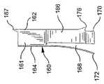
図17および図18は、本発明の他の実施形態であるロックエレメント160を例示する。ロックエレメント160は、図1〜図16の実施例のロックエレメント60と同様に機能する。ロックエレメント160はV型の本体部分161を含み、この本体部分は長手方向軸に沿ってつながる第1および第2の放射状延在壁162および164を具えている。第1の脚部166が第1の壁基端側に延在し、そして第2の脚部168が第2の壁から基端側に延在している。脚部は、図18で示すようにV型の本体部分に関して外方に広がっている。脚部166および168の各々は、基端部170および172を含み、それらはプランジャロッドアセンブリの放射状延在壁のうちの1枚に向けて曲げられている。棘176および178は、第1および第2の脚部と一体となっている。棘は基端側に向いており、注射器外筒の内側表面と係合することができるものである限り、図中に例示されるものと異なる外観を有していても良い。カッタすなわちカッティングエッジ187は、ロックエレメント160の末端部に配置される。図1〜図16の実施形態と同様に、プランジャロッドアセンブリを交代させるために通常でない力が用いられると、ロックエレメントの末端部のカッティングエッジ187はストッパを貫通し、それを使えなくする。ロックエレメントは、望ましくは金属薄板でつくられる。ロックエレメントは、図17で例示される平らな形状に予め形成される。点線は図18に示されるロックエレメント160を形づくるための、平らな基材188に作られる折り目を示している。 17 and 18 illustrate a
発明に従って使用される注射器外筒は、その長さに沿って様々な壁厚を有していても良い。薬物を収容するために使われる外筒の部分は、比較的薄く、かつストッパによる適切な密閉を確実にする弾性を有するものとすることができる。外筒の残りの部分は比較的厚く、かつ非弾性のものとして、不正改造を試みるために使用されるプライヤその他のデバイスによって強く圧迫されれば、ひびが入るようにすることができる。ロックエレメントの領域で十分な結晶性をもつことが望ましく、プランジャロッドアセンブリをロックエレメントと共に後退させることを許し得る範囲に注射器外筒が変形すると、この領域に亀裂が生じるようにすることができる。 The syringe barrel used in accordance with the invention may have various wall thicknesses along its length. The portion of the outer cylinder used to contain the drug can be relatively thin and have elasticity to ensure proper sealing by the stopper. The remaining part of the outer cylinder is relatively thick and inelastic, so that it can crack if strongly pressed by pliers or other devices used to attempt tampering. It is desirable to have sufficient crystallinity in the area of the locking element, and if the syringe barrel is deformed to such an extent that the plunger rod assembly can be retracted with the locking element, this area can be cracked.
このように、本発明によれば、簡単で信頼性高く、容易に作製可能な使い捨て注射器が提供されることが明らかである。この注射器は、使用者の側の付加的な行為がなくても更なる使用が不能ないしは操作不能となり、注射器アセンブリの再使用を試みて過度の力が使われるとプランジャロッドストッパを破損させることができるものである。 Thus, it is apparent that the present invention provides a disposable syringe that is simple, reliable, and easily manufacturable. This syringe cannot be used or operated further without any additional action on the part of the user, and the plunger rod stopper may be damaged if excessive force is used when attempting to reuse the syringe assembly. It can be done.
Claims (16)
Translated fromJapanese末端部および基端部を含む本体部分と、
プランジャロッドと係合するために前記本体部分に接続された第1の手段と、
前記注射器外筒と係合するために前記本体部分に接続され、前記ロックエレメントが前記注射器外筒に末端側には摺動可能である一方、前記注射器外筒内で基端側には実質的な摺動が阻止されるようにする第2の手段と、
前記末端部は前記カッタを安定させるための少なくとも1つの棘を備え、ストッパを切断するために前記本体部分の前記末端部に取り付けられたカッタと、
を具えたロックエレメント。A locking element for locking a syringe plunger rod having a stopper on a syringe outer cylinder,
A body portion including a distal end and a proximal end;
First means connected to the body portion for engaging a plunger rod;
Connected to the body portion for engagement with the syringe barrel, the locking element is slidable distally to the syringe barrel while substantially proximal to the syringe barrel A second means for preventing excessive sliding;
The distal end comprises at least one barb for stabilizing the cutter, and a cutter attached to the distal end of the body portion for cutting a stopper;
Lock element with
細長い本体部分およびこれに接続されたストッパと、細長い凹部と少なくとも1つのラチェット歯を画定する放射状に延在する壁と、を含むプランジャロッドアセンブリと、
前記チャンバ内に摺動可能に配置されたロックエレメントであって、前記注射器外筒の前記内側表面に係合し、前記注射器外筒の前記開放端の方向には実質的に移動しないようにされ、更に前記プランジャロッドアセンブリと係合可能で、前記プランジャロッドアセンブリとともに前記注射器外筒の前記末端部に向けて移動可能とされた当該ロックエレメントと、
前記ロックエレメントと接続されたカッタであって、前記ストッパと係合し、前記注射器外筒の前記チャンバから前記プランジャロッドアセンブリの引き戻しを試みた際に前記ストッパを切断可能な当該カッタと、
を具えた注射器アセンブリ。A syringe barrel having an inner surface forming a chamber, an open end and a distal end;
A plunger rod assembly including an elongated body portion and a stopper connected thereto, and aradially extending wall defining an elongated recess and at least one ratchet tooth ;
A locking element slidably disposed within the chamber, wherein the locking element engages the inner surface of the syringe barrel and does not substantially move in the direction of the open end of the syringe barrel. The locking element further engageable with the plunger rod assembly and movable with the plunger rod assembly toward the distal end of the syringe barrel;
A cutter connected to the locking element, which engages with the stopper and is capable of cutting the stopper when the plunger rod assembly is pulled back from the chamber of the syringe barrel;
Syringe assembly.
Applications Claiming Priority (2)
| Application Number | Priority Date | Filing Date | Title |
|---|---|---|---|
| US10/254,264US6790197B2 (en) | 2002-09-25 | 2002-09-25 | Single use syringe and plunger rod locking device therefor |
| PCT/US2003/029724WO2004028605A1 (en) | 2002-09-25 | 2003-09-23 | Single use syringe and plunger rod locking device therefor |
Publications (3)
| Publication Number | Publication Date |
|---|---|
| JP2006500174A JP2006500174A (en) | 2006-01-05 |
| JP2006500174A5 JP2006500174A5 (en) | 2006-11-09 |
| JP4533143B2true JP4533143B2 (en) | 2010-09-01 |
Family
ID=31993315
Family Applications (1)
| Application Number | Title | Priority Date | Filing Date |
|---|---|---|---|
| JP2004540143AExpired - LifetimeJP4533143B2 (en) | 2002-09-25 | 2003-09-23 | Disposable syringe and plunger rod locking device for the syringe |
Country Status (13)
| Country | Link |
|---|---|
| US (1) | US6790197B2 (en) |
| EP (2) | EP1994951B1 (en) |
| JP (1) | JP4533143B2 (en) |
| CN (1) | CN100467080C (en) |
| AT (1) | ATE405312T1 (en) |
| AU (1) | AU2003275090B2 (en) |
| BR (1) | BR0314793A (en) |
| DE (1) | DE60323114D1 (en) |
| DK (2) | DK1549370T3 (en) |
| ES (2) | ES2310670T3 (en) |
| MX (1) | MXPA05003174A (en) |
| WO (1) | WO2004028605A1 (en) |
| ZA (1) | ZA200502853B (en) |
Families Citing this family (35)
| Publication number | Priority date | Publication date | Assignee | Title |
|---|---|---|---|---|
| JP4141156B2 (en)* | 2002-03-15 | 2008-08-27 | 日本ベクトン・ディッキンソン株式会社 | Prefilled syringe with plunger retraction limit mechanism |
| ES1054272Y (en)* | 2003-03-14 | 2003-10-16 | Tyco Electronics Amp Es Sa | INSERTABLE SECURITY ELEMENT FOR SINGLE-USE DISPOSABLE SYRINGES |
| US7399293B2 (en)* | 2003-07-30 | 2008-07-15 | Becton, Dickinson And Company | Syringe assembly having disabling mechanism with tamper resistance features |
| US7331934B2 (en)* | 2003-07-30 | 2008-02-19 | Becton Dickinson Co | Syringe assembly having disabling mechanism |
| US7998104B2 (en) | 2003-11-21 | 2011-08-16 | Silk Road Medical, Inc. | Method and apparatus for treating a carotid artery |
| GB0329269D0 (en)* | 2003-12-18 | 2004-01-21 | Id Tech Ltd | Syringe |
| US20060178638A1 (en)* | 2004-12-03 | 2006-08-10 | Reynolds David L | Device and method for pharmaceutical mixing and delivery |
| MX2007007163A (en) | 2004-12-21 | 2007-08-14 | Becton Dickinson Co | Syringe assembly having disabling mechanism. |
| EP1702637A1 (en) | 2005-03-15 | 2006-09-20 | Emunio ApS | A disposable and non-reusable syringe |
| US7588556B2 (en)* | 2005-06-20 | 2009-09-15 | Id-Tech Limited | Syringe |
| US20070073226A1 (en)* | 2005-09-23 | 2007-03-29 | John Polidoro | Syringe |
| USD590500S1 (en)* | 2006-12-15 | 2009-04-14 | Daikyo Seiko, Ltd. | Syringe plunger |
| US8858490B2 (en) | 2007-07-18 | 2014-10-14 | Silk Road Medical, Inc. | Systems and methods for treating a carotid artery |
| EP2497520B1 (en) | 2007-07-18 | 2022-04-13 | Silk Road Medical, Inc. | Systems for establishing retrograde carotid arterial blood flow |
| JP2011510796A (en) | 2008-02-05 | 2011-04-07 | シルク・ロード・メディカル・インコーポレイテッド | Intervention catheter system and method |
| US9474868B2 (en)* | 2008-03-31 | 2016-10-25 | Covidien Lp | Single-use syringe assembly |
| BRPI0913380A2 (en) | 2008-06-04 | 2015-11-24 | Neovista Inc | portable radiation release system for advancing a radiation source wire |
| WO2009158648A1 (en)* | 2008-06-26 | 2009-12-30 | Becton, Dickinson And Company | Passive reuse prevention syringe that uses a retaining ring lock |
| EP2323566A2 (en) | 2008-08-13 | 2011-05-25 | Silk Road Medical, Inc. | Suture delivery device |
| US8574245B2 (en) | 2008-08-13 | 2013-11-05 | Silk Road Medical, Inc. | Suture delivery device |
| US20100076370A1 (en)* | 2008-09-23 | 2010-03-25 | Infusion Advancements, LLC. | Apparatus and methods for purging catheter systems |
| KR101702674B1 (en)* | 2008-11-26 | 2017-02-06 | 백톤 디킨슨 앤드 컴퍼니 | Single-use auto-disable syringe |
| WO2010126536A1 (en)* | 2009-04-27 | 2010-11-04 | Becton, Dickinson And Company | Passive refuse prevention syringe that uses a tip lock |
| US8066668B2 (en)* | 2009-06-26 | 2011-11-29 | Becton, Dickinson And Company | Passive reuse prevention syringe that uses a flange lock |
| USD638538S1 (en)* | 2009-07-10 | 2011-05-24 | Becton, Dickinson And Company | Syringe plunger rod |
| RU2534405C2 (en)* | 2010-05-07 | 2014-11-27 | Интьюитив Криэйшнс Пте. Лтд. | Syringe with retractable needle and cutting crown |
| US8535277B2 (en)* | 2011-03-21 | 2013-09-17 | William Marsh Rice University | Method and apparatus for dose measurement |
| US20130123712A1 (en)* | 2011-11-11 | 2013-05-16 | Becton, Dickinson And Company | Plunger Rod Retaining Anchors |
| US10159479B2 (en) | 2012-08-09 | 2018-12-25 | Silk Road Medical, Inc. | Suture delivery device |
| WO2015175537A1 (en) | 2014-05-16 | 2015-11-19 | Silk Road Medical, Inc. | Vessel access and closure assist system and method |
| US11083847B2 (en) | 2018-01-26 | 2021-08-10 | Becton, Dickinson And Company | Flush syringe with flip cap |
| CA3119997A1 (en) | 2018-11-16 | 2020-05-22 | Plas-Tech Engineering, Inc. | Systems and methods related to syringes |
| CN111773483A (en)* | 2020-08-05 | 2020-10-16 | 安徽宏宇五洲医疗器械股份有限公司 | Self-Destructing Syringe for Quantitative Distillation |
| CN112642023A (en)* | 2020-08-06 | 2021-04-13 | 安徽宏宇五洲医疗器械股份有限公司 | Self-destruction small-dose syringe capable of quantitatively drawing liquid |
| JP2023537497A (en)* | 2020-08-06 | 2023-09-01 | ベクトン・ディキンソン・アンド・カンパニー | Displacement pump mechanism with flexible reservoir, drug delivery system, patch pump and drug delivery device |
Family Cites Families (32)
| Publication number | Priority date | Publication date | Assignee | Title |
|---|---|---|---|---|
| US4386606A (en) | 1979-12-26 | 1983-06-07 | Waters Instruments, Inc. | Syringe lock |
| US4367738A (en) | 1981-10-28 | 1983-01-11 | Janssen Pharmaceutica Inc. | Pre-filled syringe for abusable drugs |
| GB2203047B (en) | 1987-02-27 | 1991-01-30 | Gilbert Henry Banks | Single-use syringe |
| IT1217047B (en)* | 1987-03-19 | 1990-03-14 | Cocchi Pietro | INJECTION SYRINGE, INTRAVENOUS SPECIES, MADE TO BE USED ONLY ONCE, WITHOUT POSSIBILITY OF RE-INSPIRATION. |
| US4781683A (en) | 1987-04-22 | 1988-11-01 | The Johns Hopkins University | Single-use, self-annulling injection syringe |
| US4731068A (en) | 1987-05-01 | 1988-03-15 | Hesse John E | Non-reloadable syringe |
| US4781684A (en) | 1987-09-03 | 1988-11-01 | Trenner Lewis E | Single use disposable hypodermic syringe |
| US4758232A (en) | 1987-09-08 | 1988-07-19 | Chak Choi K | Suction syringe with an automatic locking means |
| US5000737A (en) | 1987-09-18 | 1991-03-19 | Program For Appropriate Technology In Health (Path) | Single use disposable syringe |
| DE8804656U1 (en) | 1988-04-08 | 1988-08-04 | Bader, Mohandes, 2350 Neumünster | Medical syringe |
| US4826483A (en) | 1988-05-05 | 1989-05-02 | Paul F. Boyd | Non-reusable syringe |
| FR2634650B1 (en) | 1988-08-01 | 1990-11-02 | Labouze Joseph | NON REUSABLE SYRINGE |
| US4973310A (en) | 1988-12-30 | 1990-11-27 | Becton, Dickinson And Company | Single-use syringe |
| US4961728A (en) | 1988-12-30 | 1990-10-09 | Becton, Dickinson And Company | Single-use syringe having misuse resistant features |
| US5205825A (en) | 1989-08-07 | 1993-04-27 | Allison Alan C | Insertable element for preventing reuse of plastic syringes |
| CN1063824A (en)* | 1991-01-30 | 1992-08-26 | 莫钊 | Medical syringe capable of being discarded after being used once |
| AR243387A1 (en) | 1991-10-03 | 1993-08-31 | Cesar Gabriel Corsich | Hypodermic syringe with a locking stopper, which prevents it from being reloaded and reused. |
| US5215536A (en) | 1991-11-13 | 1993-06-01 | Merit Medical Systems, Inc. | Self-locking control syringe |
| US5531691A (en)* | 1994-02-14 | 1996-07-02 | Univec Inc. | Single use syringe assembly |
| US5562623A (en)* | 1994-02-14 | 1996-10-08 | Univec | Single-use syringe assembly including spring clip lock and plunger |
| US5733261A (en) | 1996-03-08 | 1998-03-31 | Obong; Ekoi Edet | Single use locking syringe |
| US5814017A (en) | 1996-07-18 | 1998-09-29 | Safegard Medical Products, Inc. | Single use syringe device |
| US5921961A (en)* | 1996-09-13 | 1999-07-13 | Mcgary; R. Kern | Non-reusable retractable safety syringe |
| US5769822A (en)* | 1996-09-13 | 1998-06-23 | Mcgary; R. Kern | Non-reusable retractable safety syringe |
| US5989219A (en) | 1998-01-23 | 1999-11-23 | Becton, Dickinson And Company | Single-use syringe |
| US6217550B1 (en) | 1998-07-29 | 2001-04-17 | Becton, Dickinson And Company | Single-use syringe |
| CN2379141Y (en)* | 1998-09-24 | 2000-05-24 | 普宁市罗斯医用器材有限公司 | Disposable bacterial self-destroyed type syringe |
| CN2370879Y (en)* | 1998-12-18 | 2000-03-29 | 肖龙旭 | Disposable syringe |
| US6599269B1 (en)* | 1999-12-03 | 2003-07-29 | Becton Dickinson And Company | Single-use syringe |
| US6991618B2 (en)* | 2001-09-24 | 2006-01-31 | Becton Dickinson And Company | Single use syringe and plunger rod locking device therefor |
| US6494863B1 (en) | 2001-10-15 | 2002-12-17 | Retractable Technologies, Inc. | One-use retracting syringe with positive needle retention |
| ES1054272Y (en)* | 2003-03-14 | 2003-10-16 | Tyco Electronics Amp Es Sa | INSERTABLE SECURITY ELEMENT FOR SINGLE-USE DISPOSABLE SYRINGES |
- 2002
- 2002-09-25USUS10/254,264patent/US6790197B2/ennot_activeExpired - Lifetime
- 2003
- 2003-09-23EPEP08105064.3Apatent/EP1994951B1/ennot_activeExpired - Lifetime
- 2003-09-23AUAU2003275090Apatent/AU2003275090B2/ennot_activeExpired
- 2003-09-23ESES03759361Tpatent/ES2310670T3/ennot_activeExpired - Lifetime
- 2003-09-23ATAT03759361Tpatent/ATE405312T1/ennot_activeIP Right Cessation
- 2003-09-23DEDE60323114Tpatent/DE60323114D1/ennot_activeExpired - Fee Related
- 2003-09-23CNCNB038247100Apatent/CN100467080C/ennot_activeExpired - Lifetime
- 2003-09-23EPEP03759361Apatent/EP1549370B1/ennot_activeExpired - Lifetime
- 2003-09-23ESES08105064.3Tpatent/ES2541548T3/ennot_activeExpired - Lifetime
- 2003-09-23DKDK03759361Tpatent/DK1549370T3/enactive
- 2003-09-23BRBR0314793-2Apatent/BR0314793A/ennot_activeApplication Discontinuation
- 2003-09-23MXMXPA05003174Apatent/MXPA05003174A/enactiveIP Right Grant
- 2003-09-23JPJP2004540143Apatent/JP4533143B2/ennot_activeExpired - Lifetime
- 2003-09-23WOPCT/US2003/029724patent/WO2004028605A1/enactiveApplication Filing
- 2003-09-23DKDK08105064.3Tpatent/DK1994951T3/enactive
- 2005
- 2005-04-08ZAZA2005/02853Apatent/ZA200502853B/enunknown
Also Published As
| Publication number | Publication date |
|---|---|
| CN100467080C (en) | 2009-03-11 |
| WO2004028605A1 (en) | 2004-04-08 |
| EP1994951A3 (en) | 2008-12-03 |
| DE60323114D1 (en) | 2008-10-02 |
| ATE405312T1 (en) | 2008-09-15 |
| ES2310670T3 (en) | 2009-01-16 |
| ZA200502853B (en) | 2005-12-28 |
| US6790197B2 (en) | 2004-09-14 |
| EP1994951B1 (en) | 2015-04-22 |
| EP1994951A2 (en) | 2008-11-26 |
| ES2541548T3 (en) | 2015-07-21 |
| DK1549370T3 (en) | 2008-12-01 |
| MXPA05003174A (en) | 2005-06-08 |
| CN1694742A (en) | 2005-11-09 |
| EP1549370A1 (en) | 2005-07-06 |
| EP1549370B1 (en) | 2008-08-20 |
| US20040059300A1 (en) | 2004-03-25 |
| DK1994951T3 (en) | 2015-07-20 |
| AU2003275090B2 (en) | 2009-12-10 |
| BR0314793A (en) | 2005-07-26 |
| JP2006500174A (en) | 2006-01-05 |
| AU2003275090A1 (en) | 2004-04-19 |
Similar Documents
| Publication | Publication Date | Title |
|---|---|---|
| JP4533143B2 (en) | Disposable syringe and plunger rod locking device for the syringe | |
| US7052482B2 (en) | Single use syringe and plunger rod locking device therefor | |
| US6986756B2 (en) | Single use syringe and plunger rod locking device therefor | |
| US20070299395A1 (en) | Locking device therefor | |
| KR101847792B1 (en) | Single-use auto-disable syringe | |
| EP0376697B1 (en) | Single-use syringe having mis-use resistant features | |
| JP2006500162A (en) | Disposable syringe for 2-stroke procedure | |
| EP1436021B1 (en) | Single use syringe and plunger rod locking device therefor |
Legal Events
| Date | Code | Title | Description |
|---|---|---|---|
| A521 | Request for written amendment filed | Free format text:JAPANESE INTERMEDIATE CODE: A523 Effective date:20060925 | |
| A621 | Written request for application examination | Free format text:JAPANESE INTERMEDIATE CODE: A621 Effective date:20060925 | |
| A131 | Notification of reasons for refusal | Free format text:JAPANESE INTERMEDIATE CODE: A131 Effective date:20090626 | |
| A601 | Written request for extension of time | Free format text:JAPANESE INTERMEDIATE CODE: A601 Effective date:20090925 | |
| A602 | Written permission of extension of time | Free format text:JAPANESE INTERMEDIATE CODE: A602 Effective date:20091002 | |
| A601 | Written request for extension of time | Free format text:JAPANESE INTERMEDIATE CODE: A601 Effective date:20091026 | |
| A602 | Written permission of extension of time | Free format text:JAPANESE INTERMEDIATE CODE: A602 Effective date:20091102 | |
| A521 | Request for written amendment filed | Free format text:JAPANESE INTERMEDIATE CODE: A523 Effective date:20091228 | |
| TRDD | Decision of grant or rejection written | ||
| A01 | Written decision to grant a patent or to grant a registration (utility model) | Free format text:JAPANESE INTERMEDIATE CODE: A01 Effective date:20100604 | |
| A01 | Written decision to grant a patent or to grant a registration (utility model) | Free format text:JAPANESE INTERMEDIATE CODE: A01 | |
| A61 | First payment of annual fees (during grant procedure) | Free format text:JAPANESE INTERMEDIATE CODE: A61 Effective date:20100611 | |
| R150 | Certificate of patent or registration of utility model | Ref document number:4533143 Country of ref document:JP Free format text:JAPANESE INTERMEDIATE CODE: R150 Free format text:JAPANESE INTERMEDIATE CODE: R150 | |
| FPAY | Renewal fee payment (event date is renewal date of database) | Free format text:PAYMENT UNTIL: 20130618 Year of fee payment:3 | |
| R250 | Receipt of annual fees | Free format text:JAPANESE INTERMEDIATE CODE: R250 | |
| R250 | Receipt of annual fees | Free format text:JAPANESE INTERMEDIATE CODE: R250 | |
| R250 | Receipt of annual fees | Free format text:JAPANESE INTERMEDIATE CODE: R250 | |
| R250 | Receipt of annual fees | Free format text:JAPANESE INTERMEDIATE CODE: R250 | |
| R250 | Receipt of annual fees | Free format text:JAPANESE INTERMEDIATE CODE: R250 | |
| R250 | Receipt of annual fees | Free format text:JAPANESE INTERMEDIATE CODE: R250 | |
| R250 | Receipt of annual fees | Free format text:JAPANESE INTERMEDIATE CODE: R250 | |
| R250 | Receipt of annual fees | Free format text:JAPANESE INTERMEDIATE CODE: R250 | |
| R250 | Receipt of annual fees | Free format text:JAPANESE INTERMEDIATE CODE: R250 | |
| R250 | Receipt of annual fees | Free format text:JAPANESE INTERMEDIATE CODE: R250 | |
| EXPY | Cancellation because of completion of term |