JP4533081B2 - Image encoding apparatus and method - Google Patents
Image encoding apparatus and methodDownload PDFInfo
- Publication number
- JP4533081B2 JP4533081B2JP2004297707AJP2004297707AJP4533081B2JP 4533081 B2JP4533081 B2JP 4533081B2JP 2004297707 AJP2004297707 AJP 2004297707AJP 2004297707 AJP2004297707 AJP 2004297707AJP 4533081 B2JP4533081 B2JP 4533081B2
- Authority
- JP
- Japan
- Prior art keywords
- image
- slice
- block
- determined
- blocks
- Prior art date
- Legal status (The legal status is an assumption and is not a legal conclusion. Google has not performed a legal analysis and makes no representation as to the accuracy of the status listed.)
- Expired - Fee Related
Links
Images


Classifications
- H—ELECTRICITY
- H04—ELECTRIC COMMUNICATION TECHNIQUE
- H04N—PICTORIAL COMMUNICATION, e.g. TELEVISION
- H04N19/00—Methods or arrangements for coding, decoding, compressing or decompressing digital video signals
- H04N19/85—Methods or arrangements for coding, decoding, compressing or decompressing digital video signals using pre-processing or post-processing specially adapted for video compression
- H04N19/86—Methods or arrangements for coding, decoding, compressing or decompressing digital video signals using pre-processing or post-processing specially adapted for video compression involving reduction of coding artifacts, e.g. of blockiness
- H—ELECTRICITY
- H04—ELECTRIC COMMUNICATION TECHNIQUE
- H04N—PICTORIAL COMMUNICATION, e.g. TELEVISION
- H04N19/00—Methods or arrangements for coding, decoding, compressing or decompressing digital video signals
- H04N19/10—Methods or arrangements for coding, decoding, compressing or decompressing digital video signals using adaptive coding
- H04N19/102—Methods or arrangements for coding, decoding, compressing or decompressing digital video signals using adaptive coding characterised by the element, parameter or selection affected or controlled by the adaptive coding
- H04N19/103—Selection of coding mode or of prediction mode
- H—ELECTRICITY
- H04—ELECTRIC COMMUNICATION TECHNIQUE
- H04N—PICTORIAL COMMUNICATION, e.g. TELEVISION
- H04N19/00—Methods or arrangements for coding, decoding, compressing or decompressing digital video signals
- H04N19/10—Methods or arrangements for coding, decoding, compressing or decompressing digital video signals using adaptive coding
- H04N19/102—Methods or arrangements for coding, decoding, compressing or decompressing digital video signals using adaptive coding characterised by the element, parameter or selection affected or controlled by the adaptive coding
- H04N19/117—Filters, e.g. for pre-processing or post-processing
- H—ELECTRICITY
- H04—ELECTRIC COMMUNICATION TECHNIQUE
- H04N—PICTORIAL COMMUNICATION, e.g. TELEVISION
- H04N19/00—Methods or arrangements for coding, decoding, compressing or decompressing digital video signals
- H04N19/10—Methods or arrangements for coding, decoding, compressing or decompressing digital video signals using adaptive coding
- H04N19/134—Methods or arrangements for coding, decoding, compressing or decompressing digital video signals using adaptive coding characterised by the element, parameter or criterion affecting or controlling the adaptive coding
- H04N19/136—Incoming video signal characteristics or properties
- H—ELECTRICITY
- H04—ELECTRIC COMMUNICATION TECHNIQUE
- H04N—PICTORIAL COMMUNICATION, e.g. TELEVISION
- H04N19/00—Methods or arrangements for coding, decoding, compressing or decompressing digital video signals
- H04N19/10—Methods or arrangements for coding, decoding, compressing or decompressing digital video signals using adaptive coding
- H04N19/169—Methods or arrangements for coding, decoding, compressing or decompressing digital video signals using adaptive coding characterised by the coding unit, i.e. the structural portion or semantic portion of the video signal being the object or the subject of the adaptive coding
- H04N19/17—Methods or arrangements for coding, decoding, compressing or decompressing digital video signals using adaptive coding characterised by the coding unit, i.e. the structural portion or semantic portion of the video signal being the object or the subject of the adaptive coding the unit being an image region, e.g. an object
- H04N19/174—Methods or arrangements for coding, decoding, compressing or decompressing digital video signals using adaptive coding characterised by the coding unit, i.e. the structural portion or semantic portion of the video signal being the object or the subject of the adaptive coding the unit being an image region, e.g. an object the region being a slice, e.g. a line of blocks or a group of blocks
- H—ELECTRICITY
- H04—ELECTRIC COMMUNICATION TECHNIQUE
- H04N—PICTORIAL COMMUNICATION, e.g. TELEVISION
- H04N19/00—Methods or arrangements for coding, decoding, compressing or decompressing digital video signals
- H04N19/10—Methods or arrangements for coding, decoding, compressing or decompressing digital video signals using adaptive coding
- H04N19/169—Methods or arrangements for coding, decoding, compressing or decompressing digital video signals using adaptive coding characterised by the coding unit, i.e. the structural portion or semantic portion of the video signal being the object or the subject of the adaptive coding
- H04N19/18—Methods or arrangements for coding, decoding, compressing or decompressing digital video signals using adaptive coding characterised by the coding unit, i.e. the structural portion or semantic portion of the video signal being the object or the subject of the adaptive coding the unit being a set of transform coefficients
- H—ELECTRICITY
- H04—ELECTRIC COMMUNICATION TECHNIQUE
- H04N—PICTORIAL COMMUNICATION, e.g. TELEVISION
- H04N19/00—Methods or arrangements for coding, decoding, compressing or decompressing digital video signals
- H04N19/60—Methods or arrangements for coding, decoding, compressing or decompressing digital video signals using transform coding
- H04N19/61—Methods or arrangements for coding, decoding, compressing or decompressing digital video signals using transform coding in combination with predictive coding
- H—ELECTRICITY
- H04—ELECTRIC COMMUNICATION TECHNIQUE
- H04N—PICTORIAL COMMUNICATION, e.g. TELEVISION
- H04N19/00—Methods or arrangements for coding, decoding, compressing or decompressing digital video signals
- H04N19/80—Details of filtering operations specially adapted for video compression, e.g. for pixel interpolation
- H04N19/82—Details of filtering operations specially adapted for video compression, e.g. for pixel interpolation involving filtering within a prediction loop
Landscapes
- Engineering & Computer Science (AREA)
- Multimedia (AREA)
- Signal Processing (AREA)
- Compression Or Coding Systems Of Tv Signals (AREA)
Description
Translated fromJapanese本発明は、画像符号化装置及びその方法に関し、特に、H.264と呼ばれる符号化方式を採用した画像符号化装置及びその方法におけるループフィルタを制御する技術に関する。 The present invention relates to an image encoding apparatus and method, and more particularly to H.264. The present invention relates to an image encoding apparatus employing an encoding method called H.264 and a technique for controlling a loop filter in the method.
動画像を高能率符号化するための技術として、MotionJPEGやMPEG1,2といった符号化方式が確立されている。各メーカーはこれらの符号化方式を利用して動画像を保存可能としたディジタルカメラやディジタルビデオカメラといった撮像装置或いはDVDレコーダーなどを開発し、製品化しており、ユーザーはこれらの装置或いはパーソナルコンピュータやDVDプレーヤーなどを用いて簡単に動画像を視聴することが可能となっている。 Encoding methods such as Motion JPEG and MPEG1, 2 have been established as techniques for highly efficient encoding of moving images. Manufacturers have developed and commercialized imaging devices such as digital cameras and digital video cameras or DVD recorders that can store moving images using these encoding methods, and users can use these devices or personal computers, It is possible to easily view a moving image using a DVD player or the like.
ところで、ディジタル化された動画像は膨大なデータ量となる。そこで、上記したMPEG1,2などよりも更なる高圧縮が望める動画像の符号化方式が研究され続けてきて、近年ITU−T(国際電気通信連合 電気通信標準化部門)とISO(国際標準化機構)によりH.264/MPEG−4 part10という符号化方式(以下、H.264と称す)が標準化された。 By the way, the digitized moving image has a huge amount of data. In view of this, moving picture coding systems that can achieve higher compression than MPEG1 and MPEG2 have been studied, and recently ITU-T (International Telecommunication Union Telecommunication Standardization Sector) and ISO (International Organization for Standardization). H. An encoding method called H.264 / MPEG-4 part 10 (hereinafter referred to as H.264) has been standardized.
H.264の画像符号化方法について、図9のブロック図を参照して説明する。図9はH.264の符号化ブロック図を表わすものである。図9において、減算器101、整数変換部102、量子化部103、エントロピー符号化部104、逆量子化部105、逆整数変換部106、加算器107、フレームメモリ108及び111、イントラ予測部109、ループフィルタ110、インター予測部112、動き検出部113及びスイッチ114から構成され、入力画像データを符号化処理して符号化データを出力する。 H. The H.264 image encoding method will be described with reference to the block diagram of FIG. FIG. 1 represents a H.264 coding block diagram. In FIG. 9, a
入力画像データを所定の画素数で構成される複数のブロックに分割し、そのブロック単位で処理を行う。まず、減算器101は、入力画像データから予測画像データを減算し、画像残差データを出力する。予測画像データの生成については後述する。 Input image data is divided into a plurality of blocks each having a predetermined number of pixels, and processing is performed in units of the blocks. First, the
整数変換部102は、減算器101から出力された画像残差データを直交変換処理して、変換係数を出力する。そして量子化部103は、上記変換係数を所定の量子化パラメータを用いて量子化する。 The
エントロピー符号化部104は、量子化部103で量子化された変換係数を入力し、これをエントロピー符号化して符号化データとして出力する。 The entropy encoding unit 104 receives the transform coefficient quantized by the quantization unit 103, entropy encodes it, and outputs it as encoded data.
一方、量子化部103で量子化された変換係数は予測画像データの生成にも使われる。逆量子化部105は、量子化部103で量子化された変換係数を逆量子化する。さらに、逆整数変換部106は逆量子化部105で逆量子化された変換係数を逆整数変換し、復号画像残差データとして出力する。加算器107は、復号画像残差データと後述する予測画像データとを加算し、再構成画像データとして出力する。 On the other hand, the transform coefficient quantized by the quantization unit 103 is also used for generating predicted image data. The inverse quantization unit 105 inversely quantizes the transform coefficient quantized by the quantization unit 103. Further, the inverse
再構成画像データはフレームメモリ108に保存されるとともに、ループフィルタ110でフィルタ処理されたものが、フレームメモリ111に保存される。再構成画像データの中で、以降の予測処理で参照される可能性があるデータは、フレームメモリ108または111に暫くの期間、保存される。また、ループフィルタ110はノイズを除去する為に用いられる。 The reconstructed image data is stored in the
イントラ予測部109は、フレームメモリ108に保存された再構成画像データを用いてフレーム内予測処理を行い、予測画像データを生成する。また、インター予測部112は、フレームメモリ111に保存された再構成画像データを用いて、動き検出部113によって検出された動きベクトル情報に基づいてフレーム間予測処理を行い、予測画像データを生成する。動き検出部113は入力画像データにおける動きベクトルを検出し、検出した動きベクトル情報をインター予測部112とエントロピー符号化部104へ出力する。 The
スイッチ114は、イントラ予測、インター予測のどちらを用いるか選択するための選択部である。イントラ予測部109からの出力とインター予測部112からの出力の一方を選択して、選択された予測画像データを減算器101、加算器107へ出力する。以上がH.264の画像符号化方法に関する概要である。 The switch 114 is a selection unit for selecting whether to use intra prediction or inter prediction. One of the output from the
H.264では、MPEG1,2とは異なり局部復号化された局部復号画像に対してフィルタ処理を行うループフィルタを備えることが規定されている。ここで、ループフィルタ110の構成についてさらに説明する。 H. H.264 stipulates that a loop filter that performs filter processing on a locally decoded image that is locally decoded is provided unlike MPEG1 and MPEG2. Here, the configuration of the loop filter 110 will be further described.
ループフィルタ110は、4×4画素ブロック境界又は16×16画素ブロック境界の平滑化を行い、復号画像におけるブロック歪みを除去するとともに、動き補償処理により復号画像を参照する画像にブロック歪みが伝播するのを防ぐという効果を有する。H.264ではループフィルタ処理強度の制御は主にQパラメータと呼ばれる量子化値に応じて行われる。また、画像を分割する“スライス”におけるスライスヘッダに含まれるslice_alpha_c0_offset_div2、及び、slice_beta_offset_div2という2つのパラメータにより、スライス単位でループフィルタ処理強度の変更が可能となっている。以上が、H.264におけるループフィルタに関する説明である。 The loop filter 110 smoothes the 4 × 4 pixel block boundary or the 16 × 16 pixel block boundary, removes block distortion in the decoded image, and propagates block distortion to an image that references the decoded image by motion compensation processing. Has the effect of preventing H. In H.264, the loop filter processing intensity is mainly controlled according to a quantization value called a Q parameter. In addition, the loop filter processing intensity can be changed on a slice-by-slice basis using two parameters, slice_alpha_c0_offset_div2 and slice_beta_offset_div2, included in the slice header in the “slice” that divides the image. The above is H. 264 describes a loop filter in H.264.
ところで、符号化器内のフィルタ処理の制御について開示した先行技術として、例えば特許文献1及び特許文献2が存在する。 Incidentally, for example,
特許文献1では、入力画像と動き補償された画像の差分画像を予測画像データとして使用するために、逆量子化した後に得られたDCT係数、つまり、復号画像残差データのDCT係数を用いて歪み発生を判定し、歪みの大きさにより復号画像残差データに行うフィルタ処理の強度を制御して、適応的な歪み除去を行っていた。 In
また、特許文献2では入力画像の画像パターンであるエッジの強度に応じて量子化スケールを変更し、量子化スケールが小さい時は符号量増加を抑えるために、入力画像をDCT変換した結果得られたDCT係数にフィルタ処理を行っていた。
ループフィルタ処理の制御方法に関して、前述したように、H.264では、主にQパラメータと呼ばれる量子化値に応じてループフィルタ処理を制御する。 Regarding the control method of the loop filter processing, as described above, In H.264, loop filter processing is controlled mainly in accordance with a quantization value called a Q parameter.
しかしながら、Qパラメータはバッファ容量等によっても変化してしまうので、必ずしも画像に対する視覚特性を反映したループフィルタ制御ができるとは言えない。 However, since the Q parameter changes depending on the buffer capacity or the like, it cannot always be said that the loop filter control reflecting the visual characteristics of the image can be performed.
また、上記した特許文献1に開示されたフィルタ処理の制御方法は、予測画像データと復号画像残差データを足し合わせた再構成画像データではなく、復号画像残差データのDCT係数のみを、歪み発生の判定手段として使用するものであるため、フィルタ処理に視覚特性は反映されていない。また、上記した特許文献2は、量子化スケールが小さい時に符号量増加を抑えるためにフィルタ処理を行うものであり、入力画像の画像パターンに応じてのフィルタ処理は行っていないので、フィルタ処理に視覚特性は反映されていない。すなわち、これらの従来例は、人間の画像に対する視覚特性に適したフィルタ処理制御を行っていないため、良い画質の画像が得られ難いという課題がある。 In addition, the filter processing control method disclosed in
本発明は上記の如き課題を鑑みてなされたものであり、例えばH.264による画像符号化装置及びその方法において、人間の視覚特性に適した復号画像が得られるようにフィルタ処理の制御を行うことを目的とする。 The present invention has been made in view of the above problems. It is an object of the present invention to control filter processing so that a decoded image suitable for human visual characteristics can be obtained.
上記課題を解決するために、本発明の画像符号化装置は、局部復号画像を用いた予測符号化を行う画像符号化装置であって、入力した画像データを複数画素で構成されるブロックに分割した際に、画像の平坦さ及び複雑さを基準にブロックごとの画像パターンを判定する判定手段と、前記入力した画像データを符号化する際に生成する局部復号画像における前記ブロックの境界に対して平滑化処理を行うフィルタ手段と、前記判定手段により判定された画像パターンの種類に応じた個数のスライスを構成して、各ブロックをいずれかのスライスに分類することによって、少なくとも前記画像パターンが平坦と判定されたブロックの集合体である第1のスライスと、前記画像パターンが複雑と判定されたブロックの集合体である第2のスライスとを構成するスライス構成手段と、前記スライス構成手段によって構成されたスライスごとに前記フィルタ手段における平滑化処理の強度を制御する制御手段とを備えることを特徴とする。In order to solve the above problems, an image encoding device according to the present invention is an image encoding device that performs predictive encoding using a locally decoded image, and divides input image data into blocks each composed of a plurality of pixels. Determination means for determining an image pattern for each block basedon the flatness and complexity of the image, and the boundary of the block in the locally decoded image generated when the input image data is encoded Atleast the image pattern is flattened by forming a filter means for performing a smoothing process anda number of slices according to the type of the image pattern determined by the determination means,and classifying each block into one of the slices. A first slice that is an aggregate of blocks determined to be a second slice, and a second slice that is an aggregate of blocks that are determined to have a complex image pattern The slice configuration means for configuring a, characterized in that a control means for controlling the intensity of the smoothing process in the filter means in eachslice constituted by the slice configuration means.
また、本発明の他の画像符号化装置は、局部復号画像を用いた予測符号化を行う画像符号化装置であって、入力した画像データを複数画素で構成されるブロックに分割した際に、画像の平坦さ及び複雑さを基準にブロックごとの特徴判定を行う判定手段と、前記判定手段により判定された特徴の種類に応じた個数のスライスを構成して、各ブロックをいずれかのスライスに分類することによって、少なくとも前記特徴が平坦と判定されたブロックの集合体である第1のスライスと、前記特徴が複雑と判定されたブロックの集合体である第2のスライスとを構成するスライス構成手段と、前記入力した画像データを符号化する際に生成する局部復号画像における前記ブロックの境界に対して平滑化処理を行うフィルタ手段と、前記スライス構成手段で構成された前記第1のスライスに含まれるブロックについては、前記第2のスライスに含まれるブロックよりも強く平滑化処理を行うよう、前記フィルタ手段における平滑化処理の強度を制御する制御手段とを備えることを特徴とする。Another image encoding device of the present invention is an image encoding device that performs predictive encoding using a locally decoded image, and when the input image data is divided into blocks each composed of a plurality of pixels, A determination unit that performs feature determination foreach block on thebasis of the flatnessand complexity of the image,anda number of slices corresponding to the type of feature determined by the determination unitare configured, and each block is set as one of the slices. by classifying slices constitutingat least a first slice the feature is a collection of blocks determined as flat,and asecond slicethe feature is a collection of complex determined to be the block Means, filter means for performing a smoothing process on a boundary of the block in a locally decoded image generated when the input image data is encoded, and the slice configuration Theblocks are Ruincluded inthe first slice, which is constituted by the step, to perform a smoothing process stronger than blocksincluded in the second slice, control for controlling the intensity of the smoothing process in the filter means Means.
また、本発明の画像符号化方法は、局部復号画像を用いた予測符号化を行う画像符号化方法であって、入力した画像データを複数画素で構成されるブロックに分割した際に、画像の平坦さ及び複雑さを基準にブロックごとの画像パターンを判定する判定ステップと、前記入力した画像データを符号化する際に生成する局部復号画像における前記ブロックの境界に対して平滑化処理を行うフィルタ処理ステップと、前記判定ステップにおいて判定された画像パターンの種類に応じた個数のスライスを構成して、各ブロックをいずれかのスライスに分類することによって、少なくとも前記画像パターンが平坦と判定されたブロックの集合体である第1のスライスと、前記画像パターンが複雑と判定されたブロックの集合体である第2のスライスとを構成するスライス構成ステップと、前記スライス構成ステップにおいて構成されたスライスごとに前記フィルタ処理ステップにおける平滑化処理の強度を設定する設定ステップとを有することを特徴とする。The image coding method of the present invention is an image coding method for performing predictive coding using a local decoded image,when divided into blocks composed of the image data input in a plurality ofpixels, an image of A determination step for determining an image pattern for each block on the basis offlatness and complexity, and a filter for performing a smoothing process on a boundary of the block in a locally decoded image generated when the input image data is encoded Ablock in which at least the image pattern is determined to be flat by forming a number of slices corresponding to the type of the image pattern determined in the processing step and the determination stepand classifying each block into one of the slices A first slice that is a set of blocks, and a second slice that is a set of blocks in which the image pattern is determined to be complex, And the slice configuration step of configuring, and having a setting step of setting the intensity of the smoothing process in the filtering step for eachslice that is configured in the slice configuration steps.
また、本発明の他の画像符号化方法は、局部復号画像を用いた予測符号化を行う画像符号化方法であって、入力した画像データを複数画素で構成されるブロックに分割した際に、画像の平坦さ及び複雑さを基準にブロックごとの特徴判定を行う判定ステップと、前記判定ステップにおいて判定された特徴の種類に応じた個数のスライスを構成して、各ブロックをいずれかのスライスに分類することによって、少なくとも前記特徴が平坦と判定されたブロックの集合体である第1のスライスと、前記特徴が複雑と判定されたブロックの集合体である第2のスライスとを構成するスライス構成ステップと、前記入力した画像データを符号化する際に生成する局部復号画像における前記ブロックの境界に対して平滑化処理を行うフィルタ処理ステップと、前記スライス構成ステップにおいて構成された前記第1のスライスに含まれるブロックについては、前記第2のスライスに含まれるブロックよりも強く平滑化処理を行うよう、前記フィルタ処理ステップにおける平滑化処理の強度を設定する設定ステップとを有することを特徴とする。Another image encoding method of the present invention is an image encoding method that performs predictive encoding using a locally decoded image, and when the input image data is divided into blocks each composed of a plurality of pixels, A determination step for performing feature determination foreach block basedon the flatnessand complexity of the image,anda number of slices corresponding to the type of the feature determined in the determination stepare configured, and each block is set as one of the slices. by classifying slices constitutingat least a first slice the feature is a collection of blocks determined as flat,and asecond slicethe feature is a collection of complex determined to be the block A filter processing step for performing a smoothing process on the boundary of the block in the locally decoded image generated when the input image data is encoded. If, for the block in which the slice configuration Rucontained in the constructedfirst slice in step, to perform a smoothing process stronger than blocksincluded in the second slice, the smoothing processing in the filtering process step And a setting step for setting the intensity of.
本発明によれば、入力画像の画像パターンに応じて、フィルタ処理の強度等を制御することにより、人間の視覚特性を反映した良好な復号画像が得られる。 According to the present invention, a good decoded image reflecting human visual characteristics can be obtained by controlling the strength of the filtering process and the like according to the image pattern of the input image.
以下、図面を参照しながら本発明の好適な実施の形態を説明する。 Hereinafter, preferred embodiments of the present invention will be described with reference to the drawings.
図1は本発明の実施形態となる画像符号化装置のブロック図である。図1の画像符号化装置はH.264と呼ばれる符号化方式(フォーマット)により符号化処理する構成であるが、H.264のループフィルタに相当するデブロッキングフィルタを備えるものであれば、その他のフォーマットを用いても良い。 FIG. 1 is a block diagram of an image encoding apparatus according to an embodiment of the present invention. The image encoding apparatus of FIG. H.264 is an encoding method (format). Any other format may be used as long as it includes a deblocking filter corresponding to a H.264 loop filter.
図1の画像符号化装置によれば、入力画像の画像パターンを判定し、その判定結果を用いて入力画像に適したループフィルタ処理を行うよう制御しながら符号化処理することで、人間の視覚特性を反映した復号画像を得る為の符号化データを生成することができる。以下、図1の画像符号化装置の構成について説明する。なお、図1において、図9で説明したH.264の符号化ブロック図と同じ符号のブロックに関しては、同様の構成,機能となるので、説明が重複するので省略する。 According to the image encoding apparatus of FIG. 1, the image pattern of the input image is determined, and the encoding process is performed while performing control so as to perform a loop filter process suitable for the input image using the determination result. It is possible to generate encoded data for obtaining a decoded image reflecting the characteristics. Hereinafter, the configuration of the image encoding device in FIG. 1 will be described. In FIG. 1, the H.P. Since blocks having the same reference numerals as those in the H.264 encoding block diagram have the same configuration and function, the description thereof is omitted because it is redundant.
図1において、101〜109並びに111〜114は前述したとおりである。さらに、115は入力画像データの画像パターンを判定する画像パターン判定部である。116は上記画像パターン判定部115により判定された画像パターンの判定結果に基づき、画像パターンに応じた“スライス”を構成するスライス構成部である。117は上記画像パターン判定部115及びスライス構成部116の結果に基づき、ループフィルタ120で行うフィルタ処理の強度を、構成されたスライス毎に設定可能なフィルタ処理強度設定部である。 In FIG. 1, 101 to 109 and 111 to 114 are as described above. Reference numeral 115 denotes an image pattern determination unit that determines an image pattern of input image data. Reference numeral 116 denotes a slice configuration unit that configures a “slice” corresponding to the image pattern based on the determination result of the image pattern determined by the image pattern determination unit 115.
118は画像パターン判定部115、スライス構成部116及びフィルタ処理強度設定部117の各動作を制御する制御部である。制御部118はメモリ119を用いながら制御動作を実行する。メモリ119には、各種処理に必要なプログラム等も格納されている。 Reference numeral 118 denotes a control unit that controls the operations of the image pattern determination unit 115, the slice configuration unit 116, and the filter processing
120はループフィルタである。前述したループフィルタ110と同様な構成,機能を備え、更にフィルタ処理強度設定部117からの設定命令に応じてフィルタリング処理の内容を変更できる構成となっている。以上が図1の構成である。 120 is a loop filter. The configuration and functions are the same as those of the loop filter 110 described above, and the content of the filtering process can be changed according to the setting command from the filter processing
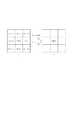
ここで上記した“スライス”に関して、H.264におけるスライスについて図10を参照して説明する。H.264におけるスライスとは、あるピクチャ内における少なくとも1つ以上の16×16画素のブロック(以下、マクロブロックと称す)をひとまとまりにしたものである。また、少なくとも1つ以上のスライスをひとまとまりにしたものが1フレームの画像であるピクチャを構成する。 Regarding the “slice” described above, H. A slice in H.264 will be described with reference to FIG. H. A slice in H.264 is a group of at least one block of 16 × 16 pixels (hereinafter referred to as a macro block) in a certain picture. In addition, a group of at least one slice constitutes a picture that is an image of one frame.
ピクチャを分割するスライスを構成する方法は、例えば、図10(a)のようにラスタスキャンオーダーで左から右、上から下へと順番にスライスを構成しても良いし、図10(b)のように市松模様のようにスライスを構成しても良いし、図10(c)のようにピクチャの一部分の領域をくりぬいたようにスライスを構成しても良い。どのような形のスライスが構成可能であるかはスライスヘッダに含まれるslice_group_map_typeで規定されている。H.264ではこのような柔軟なスライス構成によりマクロブロックを任意のスライスに分類することが可能となっている。 For example, as shown in FIG. 10A, slices may be configured in order from the left to the right and from the top to the bottom in the raster scan order as shown in FIG. A slice may be configured like a checkerboard pattern as shown in FIG. 10 or a slice may be configured such that a part of the picture is hollowed out as shown in FIG. The types of slices that can be configured are defined by slice_group_map_type included in the slice header. H. In H.264, macroblocks can be classified into arbitrary slices by such a flexible slice configuration.
続いて、図1の画像符号化装置の動作について説明を行う。ここでは上記画像パターン判定部115の構成例として、16×16画素マクロブロックに切り出した入力画像データに対して、直交変換としてアダマール変換することで画像パターン判定する例を説明する。ただし、ブロックの大きさ及び画像パターンを判定する手段、方法はこれに限ったものではない。 Next, the operation of the image encoding device in FIG. 1 will be described. Here, as an example of the configuration of the image pattern determination unit 115, an example in which image pattern determination is performed by performing Hadamard transform as orthogonal transform on input image data cut out in a 16 × 16 pixel macroblock will be described. However, the means and method for determining the block size and the image pattern are not limited to this.
入力画像データの画素データを16×16画素マクロブロックに切り出したものに対し、上記画像パターン判定部115はそれぞれアダマール変換を実行し、得られたアダマール変換係数に基づき入力画像データの画像パターンを判定する。 The image pattern determination unit 115 performs Hadamard transform on the pixel data of the input image data cut into 16 × 16 pixel macroblocks, and determines the image pattern of the input image data based on the obtained Hadamard transform coefficients. To do.
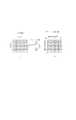
ここで、アダマール変換について図2を参照して説明する。ここでは簡単のため4×4のアダマール変換について説明する。なお、アダマール変換は直交変換の一種である。図2は上記画像パターン判定部115において4×4のアダマール変換を行った例を示しており、図2(a)が4×4画素の入力画像、図2(b)がアダマール変換することにより得られたアダマール変換係数を示している。X11〜44が入力画像の各画素値、Y11〜44が各アダマール変換係数を示している。Here, the Hadamard transform will be described with reference to FIG. Here, for simplicity, 4 × 4 Hadamard transform will be described. The Hadamard transform is a kind of orthogonal transform. FIG. 2 shows an example in which 4 × 4 Hadamard transformation is performed in the image pattern determination unit 115. FIG. 2A shows an input image of 4 × 4 pixels, and FIG. The obtained Hadamard transform coefficients are shown. X11 to44 are pixel values of the input image, and Y11 to44 are Hadamard transform coefficients.
ここでH4を4×4のアダマール変換行列、Xを入力画像信号、Yをアダマール変換係数の信号とするとアダマール変換は、
[Y]=[H4][X][H4] (式1)
で表わされる。Here, if H4 is a 4 × 4 Hadamard transform matrix, X is an input image signal, and Y is a signal of a Hadamard transform coefficient, the Hadamard transform is
[Y] = [H4 ] [X] [H4 ] (Formula 1)
It is represented by
さらに、 further,

とすれば、アダマール変換はThe Hadamard transform is
となり、1回の割り算と加算と減算のみで実行できる。なお、(式5)の左辺のY11が入力画像のDC成分、Y12〜Y44が入力画像のAC成分を表すアダマール変換係数である。Therefore, it can be executed by only one division, addition and subtraction. Note that Y11 on the left side of (Expression 5) is a DC component of the input image, and Y12 to Y44 are Hadamard transform coefficients representing the AC component of the input image.
図3は、1画素8bit(256階調)の画像データを4×4画素のブロックに切り出した入力画像に対するアダマール変換の例を示している。図3中の(a)が入力画像、(b)がアダマール変換係数を示す。図3の(1)−(a)のように入力画像ブロック内が平坦な画像の場合は、図3の(1)−(b)のように図2(b)のY11の位置に対応するアダマール変換係数が大きくなり、その他の変換係数は0となる。一方、図3の(2)−(a)のように入力画像ブロック内が複雑な画像の場合は、図3の(2)−(b)のように図2(b)のY44の位置に対応するアダマール変換係数が大きくなってくる。一般的に、入力画像ブロック内が平坦な画像の場合はAC成分を表すアダマール変換係数の総和が小さくなり、複雑な画像の場合はAC成分を表すアダマール変換係数の総和が大きくなることが知られている。FIG. 3 shows an example of Hadamard transform for an input image obtained by cutting out image data of 1 pixel 8 bits (256 gradations) into 4 × 4 pixel blocks. 3A shows an input image, and FIG. 3B shows a Hadamard transform coefficient. (1) in FIG. 3 - if the input image block is a flat image as (a), (1) in FIG. 3 - corresponding to the position of Y11 shown in FIG. 2 (b) as in (b) Hadamard transform coefficients to be increased, and other transform coefficients are 0. On the other hand, when the input image block is a complex image as shown in (2)-(a) of FIG. 3, the position of Y44 in FIG. 2 (b) is shown as (2)-(b) of FIG. The Hadamard transform coefficient corresponding to becomes larger. In general, it is known that the sum of Hadamard transform coefficients representing an AC component is small when the input image block is a flat image, and the sum of Hadamard transform coefficients representing an AC component is large when the image is complex. ing.
このような手法を用いることにより、画像パターン判定部115では、入力画像をアダマール変換することによって得られたアダマール変換係数に基づいて、平坦な画像、複雑な画像等の入力画像の画像パターンを判定する。 By using such a method, the image pattern determination unit 115 determines an image pattern of an input image such as a flat image or a complex image based on the Hadamard transform coefficient obtained by Hadamard transform of the input image. To do.
次に図1のスライス構成部116の動作を説明する。スライス構成部116は、1枚のピクチャ内において16×16画素マクロブロックを、画像パターン判定部115の判定結果に基づいて同じ画像パターン毎にひとまとまりにしてスライスを構成する。図4は、1枚のピクチャを2つのスライスで構成する例を示した図である。図4を参照しながら、以下の説明を行う。 Next, the operation of the slice configuration unit 116 in FIG. 1 will be described. The slice configuration unit 116 configures a slice by grouping 16 × 16 pixel macroblocks for each same image pattern based on the determination result of the image pattern determination unit 115 in one picture. FIG. 4 is a diagram showing an example in which one picture is composed of two slices. The following will be described with reference to FIG.
上記スライス構成部116は、上記画像パターン判定部115によって、例えば、16×16画素マクロブロック毎に判定された画像パターンに基づき、少なくとも1つ以上のマクロブロックをひとまとまりにしてスライスを構成する。例として、ある1枚のピクチャが図4(a)のように中心部分のみ細かい縦縞の画像であり、その周囲が平坦な画像の場合、まず、上記画像パターン判定部115によって中心の縦縞部分に相当するブロックで複雑な画像と判定され、その周囲の部分のブロックで平坦な画像と判定される。そして、上記スライス構成部116が判定された画像パターンに対応して、図4(b)のように、中心部分がスライス#0(Slice#0)、その周囲がスライス#1(Slice#1)というスライスを構成する。2種類以上の画像パターンが判定された場合は、スライス#0,1,2,3・・・とスライスの数が増加する。このような手法を用いることにより、スライス構成部116は、入力画像のマクロブロック毎に判定された画像パターンに基づきスライスを構成する。 The slice configuration unit 116 configures a slice by grouping at least one or more macroblocks based on, for example, the image pattern determined for each 16 × 16 pixel macroblock by the image pattern determination unit 115. As an example, when a picture is a fine vertical stripe image only in the central portion as shown in FIG. 4A and its periphery is flat, first, the image pattern determination unit 115 first converts the image into a vertical vertical stripe portion. The corresponding block is determined to be a complex image, and the surrounding block is determined to be a flat image. Then, corresponding to the image pattern determined by the slice configuration unit 116, the central part is slice # 0 (Slice # 0) and the surrounding area is slice # 1 (Slice # 1) as shown in FIG. 4B. Configure the slice. When two or more types of image patterns are determined, the number of
次に図1のフィルタ処理強度設定部117の動作を説明する。フィルタ処理強度設定部117は、上記画像パターン判定部115において判定された画像パターンに基づき、上記スライス構成部116において構成されたスライス毎にフィルタ処理の強度を設定する。ループフィルタ120では、上記フィルタ処理強度設定部117でスライス毎に設定されたフィルタ処理強度に基づき、16×16画素マクロブロックのブロック境界に対してフィルタ処理を行う。 Next, the operation of the filter processing
ここで、まずループフィルタ120で行うフィルタ処理について、図5、図6、図7を参照して説明する。ここでは、ループフィルタ処理として3×3フィルターマスクを用いた平滑化フィルタ処理を行う例について説明する。ただし、ループフィルタ処理はこのフィルタ処理に限ったものではない。 Here, filter processing performed by the loop filter 120 will be described with reference to FIGS. 5, 6, and 7. Here, an example in which smoothing filter processing using a 3 × 3 filter mask is performed as loop filter processing will be described. However, the loop filter process is not limited to this filter process.
図5(a)のf(i,j)はフィルタ処理を行う注目画素値を示し、フィルタ処理後の注目画素値f(i,j)の新しい画素値g(i,j)(図5(b))は、フィルタ処理前の画像における注目画素を取り巻く3×3フィルターマスク上の画素値、すなわち、図5(a)のf(i−1,j−1),f(i,j−1),f(i+1,j−1),f(i−1,j),f(i,j),f(i+1,j),f(i−1,j+1),f(i,j+1)及びf(i+1,j+1)の9個の値を用いて決定される。 In FIG. 5A, f (i, j) indicates a target pixel value to be filtered, and a new pixel value g (i, j) of the target pixel value f (i, j) after the filter processing (FIG. 5 ( b)) is a pixel value on the 3 × 3 filter mask surrounding the pixel of interest in the image before filtering, that is, f (i−1, j−1), f (i, j− in FIG. 5A. 1), f (i + 1, j-1), f (i-1, j), f (i, j), f (i + 1, j), f (i-1, j + 1), f (i, j + 1) And nine values of f (i + 1, j + 1).
続いて、3×3フィルターマスクを用いたフィルタ処理について、図6を参照して説明する。なお、図6に示す数字1又は2は、それぞれの位置に対応する画素値にかけるフィルタ係数を表す。例えば、図6(a)のような3×3フィルターマスクを用いたフィルタ処理の場合のフィルタ処理後の画素値g(i,j)は、 Next, filter processing using a 3 × 3 filter mask will be described with reference to FIG. Note that the
で表される。このフィルタ処理を行うことにより注目画素と注目画素の周囲の画素値との差分が小さくなり、ぼけた画像が得られる。It is represented by By performing this filtering process, the difference between the pixel of interest and the pixel values around the pixel of interest is reduced, and a blurred image is obtained.
図6(b)のような3×3フィルターマスクを用いたフィルタ処理の場合のフィルタ処理後の画素値g(i,j)は、 The pixel value g (i, j) after the filter processing in the case of the filter processing using the 3 × 3 filter mask as shown in FIG.
で表される。このフィルタ処理は、(式6)のような近傍の画素値の単純平均ではなく、自分自身の画素値の重みを周りと比較して2倍してから10で割ることにより、平均を取るというものであり、(式6)のフィルタ処理と比較してフィルタ処理後の注目画素と注目画素の周囲の画素値との差分は大きくなる。つまり、画像をぼけさせる効果は薄い。このことを、フィルタ処理強度を弱くするという。逆に、(式7)で表されるフィルタ処理から見ると、(式6)で表されるフィルタ処理強度は強いということができる。It is represented by This filtering process is not a simple average of neighboring pixel values as shown in (Equation 6), but an average is obtained by doubling the weight of its own pixel value compared to the surrounding area and then dividing by 10. Therefore, the difference between the target pixel after the filter process and the pixel values around the target pixel becomes larger than the filter process of (Expression 6). That is, the effect of blurring the image is weak. This is called reducing the filtering strength. Conversely, when viewed from the filter processing represented by (Expression 7), it can be said that the filter processing intensity represented by (Expression 6) is strong.
続いて、フィルタ処理を行う画素について図7を参照して説明する。図7は1枚のピクチャのある部分を拡大したものであり、太線で囲まれた領域はマクロブロックであり、そのマクロブロック内の小さい四角は1画素を表している。図7の網線部で示したある1つの画素を注目画素f(i,j)として前述のフィルタ処理を行う。この処理をすべての網線部の画素、つまり、16×16画素マクロブロックのブロック境界画素に対して行う。このように16×16画素マクロブロックのブロック境界画素に対しフィルタ処理を行うことにより、ブロック境界画素値の差分が小さくなりブロック歪みを低減させることができる。 Next, the pixel that performs the filtering process will be described with reference to FIG. FIG. 7 is an enlarged view of a certain part of one picture. A region surrounded by a thick line is a macroblock, and a small square in the macroblock represents one pixel. The above-described filtering process is performed with one pixel indicated by the mesh line portion in FIG. 7 as the target pixel f (i, j). This process is performed on all the pixels of the net line portion, that is, the block boundary pixels of the 16 × 16 pixel macroblock. Thus, by performing the filtering process on the block boundary pixels of the 16 × 16 pixel macroblock, the difference between the block boundary pixel values becomes small, and the block distortion can be reduced.
続いて、フィルタ処理強度設定について説明する。上記フィルタ処理強度設定部117では、上記画像パターン判定部115において判定された画像パターンに基づき、上記スライス構成部116において構成されたスライス毎に行うフィルタ処理の強度を設定する。例えば、視覚特性上ブロック歪みなどの劣化が目立ち易い、平坦な画像ブロックの集合体であるスライスにはフィルタ処理の強度を強く設定する。逆に視覚的に劣化が目立ち難い、複雑な画像ブロックの集合体であるスライスにはフィルタ処理の強度を弱く設定する。つまり図4を参照して具体的に説明すると、平坦な画像であるスライス#1にはフィルタ処理の強度を強く設定し、複雑な画像であるスライス#0にはフィルタ処理の強度を弱く設定する。ループフィルタ120に対するフィルタ処理の強弱の設定は、図6を用いて述べた手法を応用することで設定可能である。ループフィルタ120は、フィルタ処理強度設定部117からの設定情報を受けて、上記した如きフィルタ処理の内容を設定された状態に合わせて動作させ、スライス毎にフィルタ処理を変化させて、適応的なフィルタ処理を行う。 Next, filter processing strength setting will be described. Based on the image pattern determined by the image pattern determination unit 115, the filter processing
以上が図1の画像符号化装置の構成及び動作の説明である。本画像符号化装置で生成された符号化データを不図示の復号装置でデコードすれば、画像パターンに応じて適応的にフィルタリングされた画像、すなわち人間の視覚特性を反映した良好な画像が復元できる。 The above is the description of the configuration and operation of the image encoding device in FIG. If the encoded data generated by this image encoding device is decoded by a decoding device (not shown), an image that is adaptively filtered according to the image pattern, that is, a good image that reflects human visual characteristics can be restored. .
次に、これまでに述べたような、画像符号化装置におけるループフィルタ120のフィルタ処理の制御手順を、図8のフローチャートを参照して説明する。なお、図8のフローチャートは、図1における制御部118が実行する制御動作に関するものであり、制御プログラムに応じたフローを表わしたものである。 Next, the control procedure of the filter processing of the loop filter 120 in the image encoding device as described above will be described with reference to the flowchart of FIG. The flowchart in FIG. 8 relates to the control operation executed by the control unit 118 in FIG. 1 and represents a flow according to the control program.
まず、上記画像パターン判定部115は、ステップS801において、入力画像データを16×16画素に切り出した画像を入力し、ステップS802においてアダマール変換を行う。そして、ステップS803において、アダマール変換によって得られたアダマール変換係数のAC係数の総和を算出する。その総和がある閾値よりも小さい場合(noのとき)はステップS804において劣化が目立ち易いブロック(平坦といえる画像)であると判定し、ステップS805において上記スライス構成部116がスライス#1に設定する。ステップS803で総和がある閾値以上の場合(yesのとき)はステップS806において劣化が目立ち難いブロック(複雑といえる画像)であると判定し、ステップS807において上記スライス構成部116がスライス#0に設定する。
First, in step S801, the image pattern determination unit 115 inputs an image obtained by cutting input image data into 16 × 16 pixels, and performs Hadamard transform in step S802. In step S803, the sum of the AC coefficients of the Hadamard transform coefficients obtained by the Hadamard transform is calculated. When the sum is smaller than a certain threshold value (when it is no), it is determined in step S804 that the block is easily deteriorated (flat image), and the slice configuration unit 116 sets slice # 1 in step S805. . If the sum is equal toor greater than a certain threshold value in step S803 (if yes), it is determined in step S806 that the block is a block that is difficult to degrade (a complex image), and the slice configuration unit 116 sets slice # 0 in step S807. To do.
そして、ステップS808で1枚のピクチャ内におけるすべてのブロックをスライスに設定できたかを判定し、すべて終えるまでは上記の動作を各ブロックに繰り返す(ステップS808でnoのとき)。1枚のピクチャ内におけるすべてのブロックをスライスに設定し終えたら(ステップS808でyesのとき)、上記フィルタ処理強度設定部117は、ステップS809において劣化が目立ち易い平坦な画像ブロックがひとまとまりにされたスライス#1にはフィルタ処理強度を強く設定し、劣化が目立ち難い複雑な画像ブロックがひとまとまりにされたスライス#0にはフィルタ処理強度を弱く設定する。そして、ステップS810において上記ループフィルタ110はスライス毎に設定されたフィルタ処理強度に基づき、スライス毎に適応的に、ブロック境界に対して平滑化フィルタ処理を行う。以上で図8のフローは終了する。 In step S808, it is determined whether all blocks in one picture have been set as slices. The above operation is repeated for each block until all the blocks are completed (when no in step S808). When all the blocks in one picture have been set as slices (Yes in step S808), the filter processing
なお、これまでの説明では、入力画像データとして1枚のピクチャを例に説明したが、動画の場合は複数ピクチャから構成されるので、各ピクチャ(フレーム又はフィールド)毎に所定の周期で同様の処理を繰り返すことになる。 In the description so far, one picture has been described as an example of input image data. However, in the case of a moving image, since it is composed of a plurality of pictures, the same is repeated at a predetermined cycle for each picture (frame or field). The process will be repeated.
また、劣化が目立ち難い複雑な画像ブロックがひとまとまりにされたスライスには、上記した構成では弱いフィルタ処理を行うとしたが、フィルタ処理を行わないように設定することも可能である。 In addition, although weak filter processing is performed on slices in which complex image blocks that are difficult to deteriorate are grouped together in the above configuration, it may be set not to perform filter processing.
また、本実施形態であげた例では、平坦さまたは複雑さを画像パターンとして判定しているが、これら以外の特徴(輝度分布、色分布、エッジ等)を判定して、ループフィルタ処理の制御に用いる場合であっても、本発明の範疇となるのは言うまでもない。 In the example given in the present embodiment, flatness or complexity is determined as an image pattern, but other features (luminance distribution, color distribution, edge, etc.) are determined, and loop filter processing control is performed. Needless to say, even if it is used for the above, it falls within the scope of the present invention.
このように本発明の画像符号化装置によれば、入力画像の画像パターンに直接対応してループフィルタ処理を制御することにより、人間の視覚特性に適したループフィルタ処理制御ができる。これにより、人間の視覚特性を反映した良好な画像を得ることができるという効果がある。 Thus, according to the image coding apparatus of the present invention, loop filter processing control suitable for human visual characteristics can be performed by controlling loop filter processing directly corresponding to the image pattern of the input image. Thereby, there is an effect that a good image reflecting the human visual characteristics can be obtained.
<その他の実施形態>
また、本発明の目的は、前述した実施形態の機能を実現するソフトウェアのプログラムコードを記録した記憶媒体(または記録媒体)を、システムあるいは装置に供給し、そのシステムあるいは装置のコンピュータ(またはCPUやMPU)が記憶媒体に格納されたプログラムコードを読み出し実行することによっても、達成されることは言うまでもない。この場合、記憶媒体から読み出されたプログラムコード自体が前述した実施形態の機能を実現することになり、そのプログラムコードを記憶した記憶媒体は本発明を構成することになる。また、コンピュータが読み出したプログラムコードを実行することにより、前述した実施形態の機能が実現されるだけでなく、そのプログラムコードの指示に基づき、コンピュータ上で稼働しているオペレーティングシステム(OS)などが実際の処理の一部または全部を行い、その処理によって前述した実施形態の機能が実現される場合も含まれることは言うまでもない。ここでプログラムコードを記憶する記憶媒体としては、例えば、フレキシブルディスク、ハードディスク、ROM、RAM、磁気テープ、不揮発性のメモリカード、CD−ROM、CD−R、DVD、ブルーレイディスク、光ディスク、光磁気ディスクなどが考えられる。<Other embodiments>
Also, an object of the present invention is to supply a storage medium (or recording medium) that records a program code of software that realizes the functions of the above-described embodiments to a system or apparatus, and to perform computer (or CPU or CPU) of the system or apparatus. Needless to say, this can also be achieved when the MPU) reads and executes the program code stored in the storage medium. In this case, the program code itself read from the storage medium realizes the functions of the above-described embodiments, and the storage medium storing the program code constitutes the present invention. Further, by executing the program code read by the computer, not only the functions of the above-described embodiments are realized, but also an operating system (OS) running on the computer based on the instruction of the program code. It goes without saying that a case where the function of the above-described embodiment is realized by performing part or all of the actual processing and the processing is included. Examples of the storage medium for storing the program code include a flexible disk, hard disk, ROM, RAM, magnetic tape, nonvolatile memory card, CD-ROM, CD-R, DVD, Blu-ray disk, optical disk, and magneto-optical disk. And so on.
さらに、記憶媒体から読み出されたプログラムコードが、コンピュータに挿入された機能拡張カードやコンピュータに接続された機能拡張ユニットに備わるメモリに書込まれた後、そのプログラムコードの指示に基づき、その機能拡張カードや機能拡張ユニットに備わるCPUなどが実際の処理の一部または全部を行い、その処理によって前述した実施形態の機能が実現される場合も含まれることは言うまでもない。 Furthermore, after the program code read from the storage medium is written into a memory provided in a function expansion card inserted into the computer or a function expansion unit connected to the computer, the function is determined based on the instruction of the program code. It goes without saying that the CPU or the like provided in the expansion card or the function expansion unit performs part or all of the actual processing and the functions of the above-described embodiments are realized by the processing.
本発明を上記記憶媒体に適用する場合、その記憶媒体には、先に説明したフローチャート図に対応するプログラムコードが格納されることになる。 When the present invention is applied to the storage medium, the storage medium stores program codes corresponding to the flowcharts described above.
101 減算器
102 整数変換部
103 量子化部
104 エントロピー符号化部
105 逆量子化部
106 逆整数変換部
107 加算器
108 フレームメモリ
109 イントラ予測部
110 ループフィルタ
111 フレームメモリ
112 インター予測部
113 動き検出部
114 スイッチ
115 画像パターン判定部
116 スライス構成部
117 フィルタ処理強度設定部
118 制御部
119 メモリ
120 ループフィルタDESCRIPTION OF
Claims (7)
Translated fromJapanese入力した画像データを複数画素で構成されるブロックに分割した際に、画像の平坦さ及び複雑さを基準にブロックごとの画像パターンを判定する判定手段と、
前記入力した画像データを符号化する際に生成する局部復号画像における前記ブロックの境界に対して平滑化処理を行うフィルタ手段と、
前記判定手段により判定された画像パターンの種類に応じた個数のスライスを構成して、各ブロックをいずれかのスライスに分類することによって、少なくとも前記画像パターンが平坦と判定されたブロックの集合体である第1のスライスと、前記画像パターンが複雑と判定されたブロックの集合体である第2のスライスとを構成するスライス構成手段と、
前記スライス構成手段によって構成されたスライスごとに前記フィルタ手段における平滑化処理の強度を制御する制御手段とを備えることを特徴とする画像符号化装置。An image encoding device that performs predictive encoding using a locally decoded image,
Determining means for determining an image pattern for each block basedon the flatness and complexity of the image when the input image data is divided into blocks composed of a plurality of pixels;
Filter means for performing a smoothing process on a boundary of the block in the locally decoded image generated when the input image data is encoded;
By constructing a number of slices according to the type of image pattern determined by the determining means,and classifying each block into one of the slices, at least an aggregate of blocks for which the image pattern is determined to be flat Slice constructing means for constructing a first slice and a second slice that is an aggregate of blocks in which the image pattern is determined to be complex;
An image encoding apparatus comprising: control means for controlling the strength of smoothing processing in the filter means for eachslice constituted by the slice constituting means .
入力した画像データを複数画素で構成されるブロックに分割した際に、画像の平坦さ及び複雑さを基準にブロックごとの特徴判定を行う判定手段と、
前記判定手段により判定された特徴の種類に応じた個数のスライスを構成して、各ブロックをいずれかのスライスに分類することによって、少なくとも前記特徴が平坦と判定されたブロックの集合体である第1のスライスと、前記特徴が複雑と判定されたブロックの集合体である第2のスライスとを構成するスライス構成手段と、
前記入力した画像データを符号化する際に生成する局部復号画像における前記ブロックの境界に対して平滑化処理を行うフィルタ手段と、
前記スライス構成手段で構成された前記第1のスライスに含まれるブロックについては、前記第2のスライスに含まれるブロックよりも強く平滑化処理を行うよう、前記フィルタ手段における平滑化処理の強度を制御する制御手段とを備えることを特徴とする画像符号化装置。An image encoding device that performs predictive encoding using a locally decoded image,
Upon dividing the input image data block into composed of a plurality ofpixels, and determining means for performing feature determination foreach block based on the flatnessand the complexity of the image,
Thenumber of slices corresponding to the type of feature determined by the determining unitis configured, and each block is classified into one of the slices. Slice constructing means for constructing one sliceand asecond slicethat is an aggregate of blocks whose characteristics are determined to be complex ;
Filter means for performing a smoothing process on a boundary of the block in the locally decoded image generated when the input image data is encoded;
Has been for theblock is Ruincluded inthe first slice configuration by the slice construction unit, to perform a smoothing process stronger than blocksincluded in the second slice, the strength of the smoothing processing in the filter means An image encoding apparatus comprising: a control means for controlling.
入力した画像データを複数画素で構成されるブロックに分割した際に、画像の平坦さ及び複雑さを基準にブロックごとの画像パターンを判定する判定ステップと、
前記入力した画像データを符号化する際に生成する局部復号画像における前記ブロックの境界に対して平滑化処理を行うフィルタ処理ステップと、
前記判定ステップにおいて判定された画像パターンの種類に応じた個数のスライスを構成して、各ブロックをいずれかのスライスに分類することによって、少なくとも前記画像パターンが平坦と判定されたブロックの集合体である第1のスライスと、前記画像パターンが複雑と判定されたブロックの集合体である第2のスライスとを構成するスライス構成ステップと、
前記スライス構成ステップにおいて構成されたスライスごとに前記フィルタ処理ステップにおける平滑化処理の強度を設定する設定ステップとを有することを特徴とする画像符号化方法。An image encoding method for performing predictive encoding using a locally decoded image,
A determination step of determining an image pattern for each block basedon the flatness and complexity of the image when dividing the input image data into blocks composed of a plurality of pixels;
A filter processing step of performing a smoothing process on a boundary of the block in the locally decoded image generated when the input image data is encoded;
By configuring the number of slices according to the type of the image pattern determined in the determination stepand classifying each block into one of the slices, at least an aggregate of blocks for which the image pattern is determined to be flat A slice configuration step that configures a first slice and a second slice that is an aggregate of blocks in which the image pattern is determined to be complex;
An image encoding method comprising: a setting step for setting an intensity of smoothing processing in the filter processing step for eachslice configured in the slice configuration step .
入力した画像データを複数画素で構成されるブロックに分割した際に、画像の平坦さ及び複雑さを基準にブロックごとの特徴判定を行う判定ステップと、
前記判定ステップにおいて判定された特徴の種類に応じた個数のスライスを構成して、各ブロックをいずれかのスライスに分類することによって、少なくとも前記特徴が平坦と判定されたブロックの集合体である第1のスライスと、前記特徴が複雑と判定されたブロックの集合体である第2のスライスとを構成するスライス構成ステップと、
前記入力した画像データを符号化する際に生成する局部復号画像における前記ブロックの境界に対して平滑化処理を行うフィルタ処理ステップと、
前記スライス構成ステップにおいて構成された前記第1のスライスに含まれるブロックについては、前記第2のスライスに含まれるブロックよりも強く平滑化処理を行うよう、前記フィルタ処理ステップにおける平滑化処理の強度を設定する設定ステップとを有することを特徴とする画像符号化方法。An image encoding method for performing predictive encoding using a locally decoded image,
Upon dividing the input image data block into composed of a plurality ofpixels, a determination step of performing feature judging foreach block based on the flatnessand the complexity of the image,
A number of slices corresponding to the type of feature determined in the determination stepare configured, and each block is classified into one of the slices. A slice configuration step that configures one sliceand asecond slicethat is an aggregate of blocks in which the feature is determined to be complex ;
A filter processing step of performing a smoothing process on a boundary of the block in the locally decoded image generated when the input image data is encoded;
Forblocks which Ruincluded inthe first slice configured in the slice configuration steps, to perform a smoothing process stronger than blocksincluded in the second slice, the strength of the smoothing processing in the filtering process step An image encoding method comprising: a setting step for setting.
Priority Applications (2)
| Application Number | Priority Date | Filing Date | Title |
|---|---|---|---|
| JP2004297707AJP4533081B2 (en) | 2004-10-12 | 2004-10-12 | Image encoding apparatus and method |
| US11/238,703US7590296B2 (en) | 2004-10-12 | 2005-09-29 | Image coding apparatus and method in which a loop filter performs a filtering process on each image block of an image |
Applications Claiming Priority (1)
| Application Number | Priority Date | Filing Date | Title |
|---|---|---|---|
| JP2004297707AJP4533081B2 (en) | 2004-10-12 | 2004-10-12 | Image encoding apparatus and method |
Publications (3)
| Publication Number | Publication Date |
|---|---|
| JP2006114979A JP2006114979A (en) | 2006-04-27 |
| JP2006114979A5 JP2006114979A5 (en) | 2007-11-29 |
| JP4533081B2true JP4533081B2 (en) | 2010-08-25 |
Family
ID=36145395
Family Applications (1)
| Application Number | Title | Priority Date | Filing Date |
|---|---|---|---|
| JP2004297707AExpired - Fee RelatedJP4533081B2 (en) | 2004-10-12 | 2004-10-12 | Image encoding apparatus and method |
Country Status (2)
| Country | Link |
|---|---|
| US (1) | US7590296B2 (en) |
| JP (1) | JP4533081B2 (en) |
Families Citing this family (28)
| Publication number | Priority date | Publication date | Assignee | Title |
|---|---|---|---|---|
| WO2004014084A1 (en)* | 2002-07-31 | 2004-02-12 | Koninklijke Philips Electronics N.V. | Dynamic detection of blocking artefacts |
| US8625914B2 (en)* | 2013-02-04 | 2014-01-07 | Sony Corporation | Image processing system, image processing method and program |
| US20070286277A1 (en)* | 2006-06-13 | 2007-12-13 | Chen Xuemin Sherman | Method and system for video compression using an iterative encoding algorithm |
| JP2008263529A (en)* | 2007-04-13 | 2008-10-30 | Sony Corp | Coder, coding method, program of coding method and recording medium with program of coding method recorded thereon |
| EP2145482A1 (en)* | 2007-04-19 | 2010-01-20 | Thomson Licensing | Adaptive reference picture data generation for intra prediction |
| CN101389021B (en) | 2007-09-14 | 2010-12-22 | 华为技术有限公司 | Video encoding/decoding method and apparatus |
| WO2009033432A1 (en) | 2007-09-14 | 2009-03-19 | Huawei Technologies Co., Ltd. | A method and apparatus for video encoding and decoding |
| JP4958825B2 (en)* | 2008-03-28 | 2012-06-20 | キヤノン株式会社 | Moving picture coding apparatus, control method therefor, and computer program |
| US20090316793A1 (en)* | 2008-06-20 | 2009-12-24 | Yang Zhijie Michael | Method and system for adaptive deblocking for avs1-p2 |
| BRPI0921986A2 (en)* | 2008-11-25 | 2018-06-05 | Thomson Licensing | methods and apparatus for filtering out sparse matrix artifacts for video encoding and decoding |
| US8615039B2 (en)* | 2009-05-21 | 2013-12-24 | Microsoft Corporation | Optimized allocation of multi-core computation for video encoding |
| JP5359657B2 (en)* | 2009-07-31 | 2013-12-04 | ソニー株式会社 | Image encoding apparatus and method, recording medium, and program |
| JP5233897B2 (en) | 2009-07-31 | 2013-07-10 | ソニー株式会社 | Image processing apparatus and method |
| JP5604825B2 (en)* | 2009-08-19 | 2014-10-15 | ソニー株式会社 | Image processing apparatus and method |
| WO2011096071A1 (en)* | 2010-02-05 | 2011-08-11 | 株式会社 東芝 | Video encoder and video decoder |
| US8537899B1 (en)* | 2010-02-19 | 2013-09-17 | Otoy, Inc. | Fast integer and directional transforms for data encoding |
| JP5914962B2 (en)* | 2010-04-09 | 2016-05-11 | ソニー株式会社 | Image processing apparatus and method, program, and recording medium |
| US8885701B2 (en)* | 2010-09-08 | 2014-11-11 | Samsung Electronics Co., Ltd. | Low complexity transform coding using adaptive DCT/DST for intra-prediction |
| US8654860B2 (en)* | 2010-11-01 | 2014-02-18 | Mediatek Inc. | Apparatus and method for high efficiency video coding using flexible slice structure |
| US9525884B2 (en) | 2010-11-02 | 2016-12-20 | Hfi Innovation Inc. | Method and apparatus of slice boundary filtering for high efficiency video coding |
| CN102857746B (en)* | 2011-06-28 | 2017-03-29 | 中兴通讯股份有限公司 | Loop filtering decoding method and device |
| US9247258B2 (en)* | 2011-10-26 | 2016-01-26 | Qualcomm Incorporated | Unified design for picture partitioning schemes |
| US20130121422A1 (en)* | 2011-11-15 | 2013-05-16 | Alcatel-Lucent Usa Inc. | Method And Apparatus For Encoding/Decoding Data For Motion Detection In A Communication System |
| JP6289055B2 (en)* | 2013-11-27 | 2018-03-07 | 三菱電機株式会社 | Video encoding apparatus and video decoding apparatus |
| CN104392250A (en)* | 2014-11-21 | 2015-03-04 | 浪潮电子信息产业股份有限公司 | Image classification method based on MapReduce |
| JP6229770B2 (en)* | 2016-07-25 | 2017-11-15 | ソニー株式会社 | Image processing apparatus and method, recording medium, and program |
| US20220182634A1 (en)* | 2019-03-11 | 2022-06-09 | Vid Scale, Inc. | Methods and systems for post-reconstruction filtering |
| ES2967903T3 (en)* | 2019-10-03 | 2024-05-06 | Huawei Tech Co Ltd | Encoder, decoder and corresponding methods using interpolation filtering |
Family Cites Families (15)
| Publication number | Priority date | Publication date | Assignee | Title |
|---|---|---|---|---|
| JPH06311499A (en) | 1993-04-27 | 1994-11-04 | Olympus Optical Co Ltd | Picture signal decoding device |
| US5565921A (en) | 1993-03-16 | 1996-10-15 | Olympus Optical Co., Ltd. | Motion-adaptive image signal processing system |
| JPH0965336A (en)* | 1995-08-24 | 1997-03-07 | Graphics Commun Lab:Kk | Filter device |
| JPH09187005A (en) | 1995-12-28 | 1997-07-15 | Canon Inc | Encoding device |
| US5737451A (en)* | 1996-04-10 | 1998-04-07 | Eastman Kodak Company | Method and apparatus for suppressing blocking artifacts in block-transform coded images |
| KR100213089B1 (en)* | 1997-01-29 | 1999-08-02 | 윤종용 | Loop filtering method and loop filter |
| US6320987B1 (en)* | 1998-10-16 | 2001-11-20 | Neo Paradigm Labs, Inc. | Pre-DCT residue filter |
| US7003174B2 (en)* | 2001-07-02 | 2006-02-21 | Corel Corporation | Removal of block encoding artifacts |
| US6983079B2 (en)* | 2001-09-20 | 2006-01-03 | Seiko Epson Corporation | Reducing blocking and ringing artifacts in low-bit-rate coding |
| DE60230666D1 (en)* | 2001-11-29 | 2009-02-12 | Panasonic Corp | PROCESS FOR ELIMINATING CODING FORCED AND METHOD FOR VIDEO CODING AND DECODING |
| US6950473B2 (en)* | 2002-06-21 | 2005-09-27 | Seiko Epson Corporation | Hybrid technique for reducing blocking and ringing artifacts in low-bit-rate coding |
| US7212571B2 (en)* | 2003-01-31 | 2007-05-01 | Seiko Epson Corporation | Method and apparatus for DCT domain filtering for block based encoding |
| EP1602242A2 (en)* | 2003-03-03 | 2005-12-07 | Koninklijke Philips Electronics N.V. | Video encoding |
| US7724827B2 (en)* | 2003-09-07 | 2010-05-25 | Microsoft Corporation | Multi-layer run level encoding and decoding |
| US7397853B2 (en)* | 2004-04-29 | 2008-07-08 | Mediatek Incorporation | Adaptive de-blocking filtering apparatus and method for MPEG video decoder |
- 2004
- 2004-10-12JPJP2004297707Apatent/JP4533081B2/ennot_activeExpired - Fee Related
- 2005
- 2005-09-29USUS11/238,703patent/US7590296B2/ennot_activeExpired - Fee Related
Also Published As
| Publication number | Publication date |
|---|---|
| US7590296B2 (en) | 2009-09-15 |
| US20060078209A1 (en) | 2006-04-13 |
| JP2006114979A (en) | 2006-04-27 |
Similar Documents
| Publication | Publication Date | Title |
|---|---|---|
| JP4533081B2 (en) | Image encoding apparatus and method | |
| KR100612785B1 (en) | Adaptive filtering based on boundary strength | |
| TWI387348B (en) | Apparatus and method for deblocking filter processing | |
| JP5261376B2 (en) | Image coding apparatus and image decoding apparatus | |
| JP4455487B2 (en) | Decoding device, decoding method, and program | |
| KR101460608B1 (en) | Method and apparatus for encoding and decoding image usging filtered prediction block | |
| JP3466032B2 (en) | Video encoding device and decoding device | |
| CN103141094B (en) | Adaptive loop filtering method and device | |
| JP2006157481A (en) | Image encoding apparatus and method | |
| CN102132566B (en) | Image processing device and method, dynamic image encoding device and method,dynamic image decoding device and method,and encoding/decoding system and method | |
| KR101394209B1 (en) | Method for predictive intra coding for image data | |
| JP4774315B2 (en) | Image decoding apparatus and image decoding method | |
| JPWO2007091588A1 (en) | Moving picture decoding apparatus, decoded picture recording apparatus, method and program thereof | |
| JP4973886B2 (en) | Moving picture decoding apparatus, decoded picture recording apparatus, method and program thereof | |
| JP4931214B2 (en) | Image processing apparatus and method | |
| JP2011250400A (en) | Moving picture encoding apparatus and moving picture encoding method | |
| JPWO2009133845A1 (en) | Moving picture encoding / decoding apparatus and method | |
| JP2009089267A (en) | Intra prediction encoding apparatus, intra prediction encoding method, and program | |
| JP5627507B2 (en) | Moving picture encoding apparatus, moving picture decoding apparatus, moving picture encoding method, moving picture decoding method, and program | |
| JP2006005659A (en) | Image encoding apparatus and method | |
| TWI881668B (en) | Image encoding device, image decoding device, control method and program thereof | |
| CN102057679B (en) | Compressed image noise removal device and reproduction device | |
| JP2007013298A (en) | Image coding apparatus | |
| JP5111260B2 (en) | Image processing apparatus and specific area detection method | |
| JP4719108B2 (en) | VIDEO ENCODING METHOD, VIDEO ENCODING DEVICE, VIDEO ENCODING PROGRAM, AND COMPUTER-READABLE RECORDING MEDIUM CONTAINING THE PROGRAM |
Legal Events
| Date | Code | Title | Description |
|---|---|---|---|
| A521 | Request for written amendment filed | Free format text:JAPANESE INTERMEDIATE CODE: A523 Effective date:20071011 | |
| A621 | Written request for application examination | Free format text:JAPANESE INTERMEDIATE CODE: A621 Effective date:20071011 | |
| A977 | Report on retrieval | Free format text:JAPANESE INTERMEDIATE CODE: A971007 Effective date:20090630 | |
| A131 | Notification of reasons for refusal | Free format text:JAPANESE INTERMEDIATE CODE: A131 Effective date:20090714 | |
| A521 | Request for written amendment filed | Free format text:JAPANESE INTERMEDIATE CODE: A523 Effective date:20090910 | |
| RD04 | Notification of resignation of power of attorney | Free format text:JAPANESE INTERMEDIATE CODE: A7424 Effective date:20100201 | |
| TRDD | Decision of grant or rejection written | ||
| A01 | Written decision to grant a patent or to grant a registration (utility model) | Free format text:JAPANESE INTERMEDIATE CODE: A01 Effective date:20100608 | |
| A01 | Written decision to grant a patent or to grant a registration (utility model) | Free format text:JAPANESE INTERMEDIATE CODE: A01 | |
| A61 | First payment of annual fees (during grant procedure) | Free format text:JAPANESE INTERMEDIATE CODE: A61 Effective date:20100611 | |
| R150 | Certificate of patent or registration of utility model | Ref document number:4533081 Country of ref document:JP Free format text:JAPANESE INTERMEDIATE CODE: R150 Free format text:JAPANESE INTERMEDIATE CODE: R150 | |
| FPAY | Renewal fee payment (event date is renewal date of database) | Free format text:PAYMENT UNTIL: 20130618 Year of fee payment:3 | |
| LAPS | Cancellation because of no payment of annual fees |