JP4532502B2 - A device for measuring the characteristics of living tissue - Google Patents
A device for measuring the characteristics of living tissueDownload PDFInfo
- Publication number
- JP4532502B2 JP4532502B2JP2006541776AJP2006541776AJP4532502B2JP 4532502 B2JP4532502 B2JP 4532502B2JP 2006541776 AJP2006541776 AJP 2006541776AJP 2006541776 AJP2006541776 AJP 2006541776AJP 4532502 B2JP4532502 B2JP 4532502B2
- Authority
- JP
- Japan
- Prior art keywords
- voltage
- frequency
- controlled oscillator
- voltage controlled
- control signal
- Prior art date
- Legal status (The legal status is an assumption and is not a legal conclusion. Google has not performed a legal analysis and makes no representation as to the accuracy of the status listed.)
- Expired - Lifetime
Links
- WQZGKKKJIJFFOK-GASJEMHNSA-NGlucoseNatural productsOC[C@H]1OC(O)[C@H](O)[C@@H](O)[C@@H]1OWQZGKKKJIJFFOK-GASJEMHNSA-N0.000claimsabstractdescription17
- 239000008103glucoseSubstances0.000claimsabstractdescription17
- 238000012545processingMethods0.000claimsabstractdescription13
- 238000005259measurementMethods0.000claimsdescription48
- 239000003990capacitorSubstances0.000claimsdescription24
- 230000004044responseEffects0.000claimsdescription12
- 230000003321amplificationEffects0.000claimsdescription11
- 238000003199nucleic acid amplification methodMethods0.000claimsdescription11
- 230000009977dual effectEffects0.000claimsdescription3
- 230000010363phase shiftEffects0.000claimsdescription3
- 238000004804windingMethods0.000claimsdescription3
- 238000012937correctionMethods0.000abstractdescription4
- 238000013461designMethods0.000abstractdescription4
- 230000006870functionEffects0.000description14
- 238000000034methodMethods0.000description10
- 239000011159matrix materialSubstances0.000description7
- 239000012491analyteSubstances0.000description5
- 230000008901benefitEffects0.000description3
- 230000007423decreaseEffects0.000description3
- 238000010586diagramMethods0.000description3
- 229910052751metalInorganic materials0.000description3
- 239000002184metalSubstances0.000description3
- 230000008569processEffects0.000description3
- 239000000523sampleSubstances0.000description3
- 239000000758substrateSubstances0.000description3
- 238000013459approachMethods0.000description2
- 210000001124body fluidAnatomy0.000description2
- 239000010839body fluidSubstances0.000description2
- 238000004364calculation methodMethods0.000description2
- 230000001419dependent effectEffects0.000description2
- 230000000694effectsEffects0.000description2
- 239000011521glassSubstances0.000description2
- PCHJSUWPFVWCPO-UHFFFAOYSA-NgoldChemical compound[Au]PCHJSUWPFVWCPO-UHFFFAOYSA-N0.000description2
- 239000010931goldSubstances0.000description2
- 229910052737goldInorganic materials0.000description2
- 230000001965increasing effectEffects0.000description2
- 238000005316response functionMethods0.000description2
- 230000032683agingEffects0.000description1
- 230000002009allergenic effectEffects0.000description1
- 238000003491arrayMethods0.000description1
- 210000004369bloodAnatomy0.000description1
- 239000008280bloodSubstances0.000description1
- 239000000919ceramicSubstances0.000description1
- 230000008859changeEffects0.000description1
- 230000005684electric fieldEffects0.000description1
- 239000003792electrolyteSubstances0.000description1
- 230000007613environmental effectEffects0.000description1
- 238000011156evaluationMethods0.000description1
- 238000013213extrapolationMethods0.000description1
- 230000014509gene expressionEffects0.000description1
- 238000009499grossingMethods0.000description1
- 230000001939inductive effectEffects0.000description1
- 238000012886linear functionMethods0.000description1
- 239000000463materialSubstances0.000description1
- 238000000691measurement methodMethods0.000description1
- 230000007246mechanismEffects0.000description1
- 229910000510noble metalInorganic materials0.000description1
- 230000010355oscillationEffects0.000description1
- 230000000737periodic effectEffects0.000description1
- 230000000704physical effectEffects0.000description1
- 230000035790physiological processes and functionsEffects0.000description1
- 239000004033plasticSubstances0.000description1
- 239000010970precious metalSubstances0.000description1
- 239000000126substanceSubstances0.000description1
- 210000001519tissueAnatomy0.000description1
Images


Classifications
- A—HUMAN NECESSITIES
- A61—MEDICAL OR VETERINARY SCIENCE; HYGIENE
- A61B—DIAGNOSIS; SURGERY; IDENTIFICATION
- A61B5/00—Measuring for diagnostic purposes; Identification of persons
- A61B5/41—Detecting, measuring or recording for evaluating the immune or lymphatic systems
- A61B5/411—Detecting or monitoring allergy or intolerance reactions to an allergenic agent or substance
- A—HUMAN NECESSITIES
- A61—MEDICAL OR VETERINARY SCIENCE; HYGIENE
- A61B—DIAGNOSIS; SURGERY; IDENTIFICATION
- A61B5/00—Measuring for diagnostic purposes; Identification of persons
- A61B5/05—Detecting, measuring or recording for diagnosis by means of electric currents or magnetic fields; Measuring using microwaves or radio waves
- A—HUMAN NECESSITIES
- A61—MEDICAL OR VETERINARY SCIENCE; HYGIENE
- A61B—DIAGNOSIS; SURGERY; IDENTIFICATION
- A61B5/00—Measuring for diagnostic purposes; Identification of persons
- A61B5/145—Measuring characteristics of blood in vivo, e.g. gas concentration or pH-value ; Measuring characteristics of body fluids or tissues, e.g. interstitial fluid or cerebral tissue
- A61B5/14532—Measuring characteristics of blood in vivo, e.g. gas concentration or pH-value ; Measuring characteristics of body fluids or tissues, e.g. interstitial fluid or cerebral tissue for measuring glucose, e.g. by tissue impedance measurement
Landscapes
- Health & Medical Sciences (AREA)
- Life Sciences & Earth Sciences (AREA)
- Physics & Mathematics (AREA)
- Medical Informatics (AREA)
- Surgery (AREA)
- Biophysics (AREA)
- Pathology (AREA)
- Engineering & Computer Science (AREA)
- Biomedical Technology (AREA)
- Heart & Thoracic Surgery (AREA)
- Veterinary Medicine (AREA)
- Molecular Biology (AREA)
- Public Health (AREA)
- Animal Behavior & Ethology (AREA)
- General Health & Medical Sciences (AREA)
- Optics & Photonics (AREA)
- Emergency Medicine (AREA)
- Immunology (AREA)
- Vascular Medicine (AREA)
- Nuclear Medicine, Radiotherapy & Molecular Imaging (AREA)
- Radiology & Medical Imaging (AREA)
- Investigating Or Analyzing Materials By The Use Of Electric Means (AREA)
- Measurement Of The Respiration, Hearing Ability, Form, And Blood Characteristics Of Living Organisms (AREA)
Abstract
Description
Translated fromJapanese本出願は、2003年12月2日に出願された国際特許出願PCT/CH03/00795の優先権を主張する。この出願の開示は、全て参照として本明細書に組み込まれる。本発明は、生きている組織の特性、より詳しくは組織のグルコースレベルを測定するための装置、およびその方法に関する。 This application claims the priority of international patent application PCT / CH03 / 00795 filed on December 2, 2003. The entire disclosure of this application is incorporated herein by reference. The present invention relates to a device for measuring characteristics of living tissue, and more particularly to glucose levels in tissue, and a method thereof.
生きている組織内のグルコースレベルは、患者の皮膚に電極を配置し、適切な電気信号に対する電極配列の応答を測定することによって、体内への侵入を伴うことなく(non-invasively)、行うことができることが知られている。このような技術は、WO 02/069791に記載されており、これの開示内容は本明細書に全て包含される。 Glucose levels in living tissue are performed non-invasively by placing electrodes on the patient's skin and measuring the response of the electrode array to the appropriate electrical signal It is known that Such a technique is described in WO 02/069791, the disclosure of which is fully incorporated herein.
このタイプの装置は、検体に付される電極配列と、所定の周波数範囲内でのAC電圧を生成するための信号源としての電圧制御発振器とを備えている。AC電圧は、電極配列に印加される。電極配列の、組織の誘電特性に応じた電極配列上の電圧等の応答は、処理回路に供給される。 This type of apparatus includes an electrode array attached to a specimen and a voltage-controlled oscillator as a signal source for generating an AC voltage within a predetermined frequency range. An AC voltage is applied to the electrode array. The response of the electrode array, such as the voltage on the electrode array according to the dielectric properties of the tissue, is supplied to the processing circuit.
この装置が、グルコースを満足に観察できるとしても、慎重な較正が必要であり、高精度の測定結果を得るために明確な条件下で実施される必要がある。 Even though this device can satisfactorily observe glucose, careful calibration is required and it must be performed under well-defined conditions to obtain highly accurate measurement results.
WO 02/069791の装置は、生きている組織のパラメータを測定するための装置の一例である。同様のタイプの装置が、組織の電気AC場への応答に影響を与える、誘電定数またはイオン濃度等の他の特性を測定するために用いられることができる。 The device of WO 02/069791 is an example of a device for measuring parameters of living tissue. Similar types of devices can be used to measure other properties, such as dielectric constant or ion concentration, that affect the tissue's response to an electrical AC field.
このタイプの装置には、高精度が求められる。また、携帯装置では、低電力消費および低供給電圧が求められる。 This type of device requires high accuracy. Also, portable devices require low power consumption and low supply voltage.
したがって、本発明の第1の側面においては、低供給電力を有するこのタイプの装置を提供することを目的とする。 Accordingly, it is an object of the first aspect of the present invention to provide an apparatus of this type having a low supply power.
そこで、これ、および本明細書の記載が進むに従ってより容易に明確になるであろう本発明のさらなる目的を実現するために、請求項1の装置が用いられる。 Thus, to achieve this and further objects of the invention that will become more readily apparent as the description proceeds, the apparatus of
本発明のこの側面に従った装置では、電圧制御発振器(VCO)は、増幅率制御信号によって増幅率を設定可能な少なくとも1つの電圧制御増幅器を具備する。VCOは、VCOの動作の周波数を決定する電圧制御キャパシタを伴った少なくとも1つのタンク回路をさらに具備する。この装置は、電圧制御キャパシタの両端のDC電圧がゼロに近いときに、増幅率が増加するように増幅率制御信号を制御するよう適合されている。 In the device according to this aspect of the invention, the voltage controlled oscillator (VCO) comprises at least one voltage controlled amplifier whose gain can be set by means of the gain control signal. The VCO further comprises at least one tank circuit with a voltage controlled capacitor that determines the frequency of operation of the VCO. The device is adapted to control the gain control signal such that the gain increases when the DC voltage across the voltage control capacitor is near zero.
このことは、損失が大きくなるDC電圧がゼロに近いときの電圧制御キャパシタの動作を可能とする。これにより、適度の供給電圧および電力消費で、広範囲の周波数を生成できる。 This enables the operation of the voltage controlled capacitor when the DC voltage at which loss increases is close to zero. Thereby, a wide range of frequencies can be generated with an appropriate supply voltage and power consumption.
本発明の第2の側面においては、簡単な回路で正確な測定を可能とする上記のタイプの装置を提供することを目的とする。 In the second aspect of the present invention, an object of the present invention is to provide an apparatus of the above type that enables accurate measurement with a simple circuit.
この第2の側面は、請求項7の装置により達成される。 This second aspect is achieved by the device of claim 7.
この側面の装置によれば、処理回路は、AC入力電圧を整流して整流された信号を生成する少なくとも1つのダイオードを、この信号を平滑にするための積分器に加えて具備する。整流され、平滑にされた信号(またはこれらから得られた信号)は、A/Dコンバータに供給され、デジタル値へと変換される。このデジタル値は、入力電圧のAC振幅に、比例ではないが、依存する。したがって、それは、入力電圧のAC振幅に実質的に比例する信号値へと、例えば較正関数または参照表によって変換される。実質的に比例という文言は、信号値が、デジタル値よりもAC振幅により比例し、少なくとも近似においては、AC振幅に正確に比例する値を必要とする計算のために用いられることができることを指す。 According to the apparatus of this aspect, the processing circuit comprises at least one diode that rectifies the AC input voltage to produce a rectified signal, in addition to an integrator for smoothing the signal. The rectified and smoothed signal (or the signal obtained therefrom) is supplied to an A / D converter and converted into a digital value. This digital value depends on the AC amplitude of the input voltage, but not proportionally. Thus, it is converted into a signal value that is substantially proportional to the AC amplitude of the input voltage, for example by a calibration function or a look-up table. The term substantially proportional means that the signal value is more proportional to the AC amplitude than the digital value, and at least in approximation, can be used for calculations that require a value that is exactly proportional to the AC amplitude. .
この方法では、アナログ回路は、正確さを失うことなく簡略化される。具体的には、アナログ回路は、入力電圧のAC振幅に正確に比例する信号を供給する必要はない。 In this way, the analog circuit is simplified without loss of accuracy. Specifically, the analog circuit need not provide a signal that is exactly proportional to the AC amplitude of the input voltage.
本発明の第2の側面では、利用可能なデータを有効に活用する正確な測定を可能にする、上記したタイプの装置、および対応する測定方法を提供することである。 The second aspect of the present invention is to provide an apparatus of the type described above and a corresponding measurement method that enables accurate measurements that make effective use of available data.
この第2の側面は、請求項14の装置および請求項29の方法によって達成される。 This second aspect is achieved by the apparatus of claim 14 and the method of claim 29.
本発明のこの側面では、一連の周波数fiのAC電圧が生成され、電極配列を介して検体に印加される。各周波数fiにおける対応する一連の測定値Miが求められる。各測定値Miは、対応する周波数における検体の誘電特性に依存する。パラメータb1乃至bkを用いた関数M(f,b0,・・・・,bk)が、与えられた周波数fiまたはこれらから得られた値を介して測定値miに対してフィッティングされ、よってb1乃至bkが決定される。b1乃至bkの少なくとも一部は、次いで、所望の特性を求めるために、例えば先の較正測定による較正データを用いて、用いられる。In this aspect of the present invention, an AC voltage of a series of frequency fi is generated and applied to the sample via the electrode array. A corresponding series of measured values Mi at each frequency fi is determined. Each measured value Mi depends on the dielectric properties of the analyte at the corresponding frequency. Parameterb 1 tob k the function M using(f, b 0, ····, b k) is, for a given frequencyf i or measurementsm i through the values obtained from these Fitting is thus performed and b1 to bk are determined. At least some of b1 to bk are then used, for example using calibration data from previous calibration measurements, to determine the desired characteristics.
関係するフィッティング処理が、用いられる全ての測定値からの情報を利用し、統計的なばらつきによる影響を補償するので、このようにして得られた結果は、高い精度を有する。 Since the relevant fitting process uses information from all the measurement values used and compensates for the effects of statistical variations, the results obtained in this way have a high accuracy.
本発明の第3の側面では、正確な測定を可能とする上記のタイプの装置を提供することを目的とする。 In the third aspect of the present invention, an object of the present invention is to provide an apparatus of the above type that enables accurate measurement.
この第2の側面は、請求項19の装置によって達成される。 This second aspect is achieved by the apparatus of
この側面は、外部電極の非対称の構成が、より強固で、より信頼性の高い信号を提供するという発見に基づいている。 This aspect is based on the discovery that the asymmetric configuration of the external electrodes provides a stronger and more reliable signal.
本発明の最後の側面では、生理学上の互換性を有する上記のタイプの装置を提供することを目的とする。 In a final aspect of the invention, it is an object to provide a device of the above type that is physiologically compatible.
この最後の側面は、請求項22の装置によって達成される。ここで、電極への全てのスルーコンタクトは、生物学的に不活性な材料で覆われている。スルーコンタクトは、有害またはアレルギー誘発性の物質の生成源であることが発見された。よって、スルーコンタクトを覆うことによって、装置の生物学的な互換性(biocompatibility)を上げることができる。 This last aspect is achieved by the device of
様々な側面に従った装置の要素は、個別にまたは組み合わせて用いられることができることに留意されねばならない。 It has to be noted that the elements of the device according to various aspects can be used individually or in combination.
本発明、および上記した以外の目的ついての以下の詳細な説明を熟考することにより、本発明はより良く理解され、上記以外の目的は明確となるであろう。このような説明は、添付の図面を参照している。 The invention will be better understood and other objects will become apparent by consideration of the invention and the following detailed description of the objects other than those described above. Such description refers to the accompanying drawings.
装置の基本的な設定
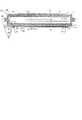
図1は、対象のグルコースレベルを測定するための装置100の断面図を示している。しかしながら、同じタイプの装置が、上記のように電気AC場を印加される組織の応答に影響する生きている組織の他のあらゆるパラメータを測定可能であることに留意されなければならない。グルコースレベルとは別に、このような特性は、例えば組織の電解質レベルであり得る。Basic Setup of Device FIG. 1 shows a cross-sectional view of a
図1の装置は、電極板2によって一方を封止された筐体を具備する。ディスプレイ3は、電極板2と反対側に配置される。電子回路が、電極板2とディスプレイ3との間に配置される。 The apparatus shown in FIG. 1 includes a housing sealed on one side by an electrode plate 2. The display 3 is disposed on the side opposite to the electrode plate 2. An electronic circuit is disposed between the electrode plate 2 and the display 3.
電極板2は、平坦な、電気的に絶縁性の基板4を具備する。ストリップ電極5は、絶縁基板4の外側7上に配置されている。ストリップ電極5は、絶縁層5aおよび、外部の環状電極6によって覆われている。環状電極は、ストリップ電極5の少なくとも一部を、またはこれを完全に囲む。絶縁基板4の内側8は接地電極9により覆われている。複数のスルーコンタクト10は、外側電極6を接地電極9に接続する。さらなるスルーコンタクト11は、ストリップ電極5の一端を内面8上に配置されたコンタクトパッド12に接続する。 The electrode plate 2 includes a flat, electrically insulating substrate 4. The strip electrode 5 is disposed on the outer side 7 of the insulating substrate 4. The strip electrode 5 is covered with an
第1の温度センサ15が、接地電極9上に、直接に熱的接触して配置されている。スルーコンタクト10の多数は、接地電極9が外側電極6の温度、従って検体の温度に追随することを保証する。検体の表面は、点線16により示されている。 A
リードまたはバネ18が設けられて、接地電極9、コンタクトパッド12、第1の温度センサ15を電気部品の組み立て品を形成するプリント回路基板19上に配置された電子回路に接続する。プリント回路基板19が、有利な形態としては、本装置の電極板2の実質的に反対側に配置される。回路に電源を供給するバッテリー21が、プリント回路基板19と電極板2との間に配置される。 Leads or
第2の温度センサ22が、プリント回路基板19上に、直接に熱的接触して配置される。 A
装置100の回路構成は、WO 02/069791に記載されているものとすることができる。使用可能な他の回路が、図2のブロック回路部に示されている。この回路は、選択可能な周波数ωのサイン波信号VVCOまたは他の周期的信号を生成するための信号源としての電圧制御発振器(VCO)を具備する。この信号は、増幅器32に供給される。増幅器32の出力は、抵抗R1を介して信号点34と測定回路37の第1の入力u1に接続される。また、増幅器32の出力は、測定回路37の第2の入力u2に直接供給される。共振回路35は、インダクタンスLおよびキャパシタCを具備し、信号点34と接地との間に接続される。The circuit configuration of the
測定回路37の動作が、以下に説明される。測定回路37の出力は、例えば入力u1、u2でのAC電圧の振幅および(または)相対的な位相であり、マイクロプロセッサ38に供給される。マイクロプロセッサ38は、VCO31の動作も制御する。 The operation of the
マイクロプロセッサ38は、第1、第2の温度センサ15、22からの第1、第2の温度信号T1、T2をサンプル化する。マイクロプロセッサ38は、また、ディスプレイ装置3、使用者が制御可能な入力装置40、外部コンピュータへのインターフェース41を制御する。メモリ42が、較正パラメータ、測定結果、さらなるデータ、マイクロプロセッサ38のためのファームウェアを格納するために設けられる。メモリ42の少なくとも一部は、不揮発性である。 The
図2の装置のインダクタンスLは、コイル、および(または)キャパシタCのリードと電極によって生成されることができる。インダクタンスの値は、適度な正確さで一般的に求められる。 The inductance L of the device of FIG. 2 can be generated by the coil and / or the lead and electrode of the capacitor C. The inductance value is generally determined with reasonable accuracy.
図2の装置のキャパシタCは、ストリップ電極5と外側電極6との間に形成され、検体のプローブのために用いられる。この目的のために、電極が、図1に示すように対象の皮膚16上に配置される。 The capacitor C in the apparatus of FIG. 2 is formed between the strip electrode 5 and the outer electrode 6 and is used for the probe of the specimen. For this purpose, electrodes are placed on the subject's
対象の皮膚に良好で永続的に接触するために、本装置は、有利な形態としては腕または脚に取り付けられ、適当なホルダまたはリストバンド43が設けられる。 In order to have good and permanent contact with the subject's skin, the device is advantageously attached to the arm or leg and provided with a suitable holder or wristband 43.
まとめると、図1および図2に示す装置は、
所定の周波数範囲内でAC電圧を生成するための電圧制御発振器と、
電極5、6を具備する電極配列と、
電極配列の電気信号に対する応答を測定し、これからグルコースレベルまたは他のパラメータを導き出すための要素31乃至33、37、38を含む処理回路と、
を具備する。In summary, the apparatus shown in FIG. 1 and FIG.
A voltage controlled oscillator for generating an AC voltage within a predetermined frequency range;
An electrode arrangement comprising electrodes 5, 6;
A processing
It comprises.
また、この装置は、少なくとも2つの温度センサ15、22を具備してもよい。これらのセンサの信号は、体の皮膚温度、環境温度に、異なる形態で依存する。これらの温度の一方、または有利な形態として両方が、グルコースレベルを求める際に考慮に入れることができる。 The apparatus may also include at least two
操作方法
本装置の動作の基本原理は、WO 02/069791に記載されている。Method of operation The basic principle of operation of the device is described in WO 02/069791.
患者の体液内のグルコース濃度を測定するために、マイクロプロセッサ38は、例えば、VCO1の周波数掃引からなる測定サイクルを開始することができる。この掃引は、共振回路35の予想される共振周波数f0を超えた周波数fmaxから開始し、共振周波数f0未満の周波数fminまで変化する(またはこの逆)。この掃引の間、共振回路の電気的特性は変化する。測定回路Aによって決定された振幅は、WO 02/069791に記載されているように、特性周波数f0にいて最小A0まで減少する。同様に位相シフトphiはゼロを通過する。In order to measure the glucose concentration in the patient's body fluid, the
マイクロプロセッサ38は、測定対象者の血液、体液、組織の生理学的な状態を示す入力値として、A0および(または)f0、または本装置の周波数応答を示す他のパラメータを測定する。A0および(または)f0の入力値に加えて、マイクロプロセッサ38は、さらなる入力値として温度値T1、T2を測定する。適当な較正データを用いて、グルコースレベルが、これらの入力値から求められることができる。 The
このような較正データは、当業者に知られている方法を用いて直接的に、入力値の範囲に亘る較正測定値から決定されることができる。 Such calibration data can be determined directly from calibration measurements over a range of input values using methods known to those skilled in the art.
一般に、マイクロプロセッサ38は、以下のタイプの公式
g=F(s1,s2,・・・sN,a0,a1,・・・aM) (1)
を用いてN個の測定された入力値s1,s2,・・・sN(N>0)からグルコースレベルg(またはこれを示すパラメータ)を求める。関数Fは、M+1個のパラメータa0,a1,・・・aM(M≧0)を有する。これらの幾つかは較正測定値から求められなければならない。In general, the
Is used to determine the glucose level g (or a parameter indicating this) from the N measured input values s1 , s2 ,... SN (N> 0). The function F has M + 1 parameters a0 , a1 ,... AM (M ≧ 0). Some of these must be determined from calibration measurements.
測定された入力値siは、例えば振幅A0、対応する周波数f0、温度T1、T2から直接的にまたは間接的に求められる。入力値は、例えば、最新の測定値または時間平均値または所定数の最新の測定値のメジアンとすることができる。使用可能な入力値については、後述の「未加工の信号のさらなる処理」の項で説明する。The measured input value si is obtained directly or indirectly from, for example, the amplitude A0, the corresponding frequency f0, and the temperatures T1 and T2. The input value can be, for example, the latest measured value or time average value or the median of a predetermined number of latest measured values. Usable input values are described in the section “Further processing of the raw signal” below.
関数Fは、経験的なものであっても良いし、関係するメカニズムの物理的性質を記述するモデルに少なくとも一部が基づいていても良い。 The function F may be empirical or based at least in part on a model that describes the physical properties of the mechanisms involved.
グルコースレベルgと測定値siとの関係が、近似では線形であるとすると、
g=a0+a1・s1+a2・s2+・・・aN・sN (2a)
を得る。ここで、M=Nである。If the relationship between the glucose level g and the measured value si is linear in the approximation,
g = a0 + a1 · s1 + a2 · s2 +... aN · sN (2a)
Get. Here, M = N.
等式(2a)はパラメータajだけでなく入力値siにおいても線形である利点を有する。これにより、評価だけでなく較正もが簡略化される。しかしながら、より精緻なモデルももちろん用いることができる。Equation (2a) has the advantage of being linear not only in the parameter aj but also in the input value si . This simplifies calibration as well as evaluation. However, more elaborate models can of course be used.
パラメータa0,a1,・・・aNを求めるために、少なくともN+1回の一連の較正測定が実行されなければならない。各較正測定は、入力値Sjと、例えば侵入性の(invasive)方法等の従来の手段によって測定された参照グルコースレベルgを求めることを具備する。In order to determine the parameters a0 , a1 ,... AN , at least N + 1 series of calibration measurements must be performed. Each calibration measurement comprises determining an input value Sj and a reference glucose level g measured by conventional means such as, for example, an invasive method.
最も簡便な手法では、パラメータaiが、次いで、較正測定に最も適する等式(2)または(2a)を発見するためにパラメータaiを変化させる従来の最小2乗フィッティングアルゴリズムから求められることができる。適切なアルゴリズムは、当業者に知られており、例えばCambridge University Pressの1992年の第2版、15章のPress, Teukolsky, Vetterling, Flanneryによる“Numerical Recipes in C”に記載されている。In the simplest approach, the parameter ai can then be determined from a conventional least square fitting algorithm that varies the parameter ai to find the equation (2) or (2a) that is most suitable for the calibration measurement. it can. Appropriate algorithms are known to those skilled in the art and are described, for example, in “Numerical Recipes in C” by Press, Teukolsky, Vetterling, Flannery,
パラメータaiが得られたら、グルコースレベルgが、等式(2)または(2a)から、入力値Sjの測定値に基づいて求められることができる。Once the parameter ai is obtained, the glucose level g can be determined from equation (2) or (2a) based on the measured value of the input value Sj .
パラメータの少なくとも一部の再較正を、規則的な間隔で、または検体から装置100を取り外した後で、行うことが望ましいかもしれない。 It may be desirable to recalibrate at least some of the parameters at regular intervals or after removing the
以下では、本装置の様々な有利な面が、詳細に説明される。 In the following, various advantageous aspects of the device will be described in detail.
電圧制御発振器
原則として、様々な形態の電圧制御発振器が、本発明中で用いられることに適している。そのようなものの1つが、WO 02/069791の図9に示されている。しかしながら、以下に、電圧制御発振器の有利な実施形態が記載される。この電圧制御発振器は、小さな供給電圧で動作し、消費電力が少なく、広い範囲の周波数で発振し、少ない歪でサイン波信号を生成する。Voltage-controlled oscillators In principle, various forms of voltage-controlled oscillators are suitable for use in the present invention. One such is shown in FIG. 9 of WO 02/069791. In the following, however, advantageous embodiments of the voltage controlled oscillator are described. This voltage controlled oscillator operates with a small supply voltage, consumes less power, oscillates over a wide range of frequencies, and generates a sine wave signal with less distortion.
図3の電圧制御発振器31は、インダクタンスL1、L2の2つの対称的なタンク回路と、電圧制御キャパシタ(バラクターダイオード)D1、D2を具備する。電圧制御キャパシタD1、D2の容量は、周波数制御電圧または周波数制御信号V1によって制御される。また、VCO31は、2つの増幅器を具備する。2つの増幅器は、それぞれ、デュアルゲートFETT1、T2から構成される。トランジスタT1、T2の増幅率は、増幅率制御電圧または増幅率制御信号V2によって制御される。要素L1、D1、L2、D2、T1、T2は、T1、T2のドレインの電圧が位相180°ずれてタンク回路の共振周波数において共振するように接続されている。トランジスタT1、T2のドレイン、したがって増幅器の出力は、キャパシタC1、C2、変圧器TRの一次巻線を介して相互に接続されている。変圧器TRの二次巻線は、アナログ接地AGND(ほぼ2.5ボルトである)に対する出力電圧VVCOを生成する。3 includes two symmetrical tank circuits having inductances L1 and L2, and voltage control capacitors (varactor diodes) D1 and D2. The capacitances of the voltage control capacitors D1 and D2 are controlled by a frequency control voltage or a frequency control signal V1. The
VCO31の周波数は、周波数制御電圧V1を介して選択されることができる。周波数制御電圧V1は、例えば、マイクロプロセッサ38によって生成されることができる。典型的には、周波数制御電圧V1は、−10乃至+5ボルトの範囲に亘る。しかしながら、+5ボルトに近づくと、D1、D2の両端のDC電圧は減少し、したがってD1、D2の損失が増加する。これらの損失を補償するために、増幅器の増幅率は、周波数制御電圧V1に応じて較正される。これは、電圧制御キャパシタD1、D2の両端のDC電圧がゼロに近いときに増幅制御信号V2、したがって増幅器増幅率を上げることによって行われる。 The frequency of the
増幅率制御電圧V2は、マイクロプロセッサ38によって生成されることができる。例えば、マイクロプロセッサ38は、RAM/ROM42内の較正データにアクセスすることができる。このデータは、周波数制御電圧V1の各値についての、増幅率制御電圧V2またはそれから得られる変数の適切な値を供給する。 The amplification factor control voltage V <b> 2 can be generated by the
有利な形態として、増幅率制御電圧V2は、出力電圧VVCOまたは測定回路37の第2の入力u2での信号を監視し且つ増幅率制御電圧V2の振幅を一定値に保つよう制御するフィードバックループによって生成される。このことは、電圧制御キャパシタD1、D2の両端のDC電圧がゼロに近づいたときに増幅率制御電圧V2を増加させることに繋がる。Advantageously, the gain control voltage V2 is a feedback loop that monitors the output voltage VVCO or the signal at the second input u2 of the measuring
電圧V2をフィードバックループ内で制御することは、出力電圧が、VCO31の動作パラメータが、例えば温度および(または)回路の経年によって変動したとしても、実質的に一定に保たれるという利点を有する。このことは、測定回路37が所定の電圧範囲でのみ最適に動作するように設計されている場合に特に重要であり、このことによって、印加された電場に対する体の応答が非線形であることが測定された信号に影響を与えないことが保証される。 Controlling the voltage V2 in the feedback loop has the advantage that the output voltage remains substantially constant even if the operating parameters of the
V2を制御するためのフィードバックループは、アナログ回路を用いて、またはマイクロプロセッサ38の補助の下に、実行されることができる。マイクロプロセッサ38を用いると回路設計が簡略化されるため有利である。しかしながら、フィードバックループを実施することが本装置の電力消費を不要に増加させないように配慮されなければならない。 The feedback loop for controlling V2 can be implemented using analog circuitry or with the aid of the
したがって、フィードバックループを有利に実施するには、V2の適切な値を発見するためにVCOが不要に長時間に亘って動作することを避けるべきである。上記のように、マイクロプロセッサ38は、VCO31の周波数掃引からなる測定サイクルを開始することができる。この掃引は、例えば、周波数fmaxで開始して周波数fminまで達し、また所定の一連の周波数fiにおいて繰り返し測定することからなる。有利な実施形態では、RAM/ROM42は、各周波数fiについての、導関数d(fi)=dV2/df|f=fiの計算を可能とする較正データを保持する。このデータを用いて、以下のステップが取られて電圧V2の値が制御される。Thus, in order to advantageously implement the feedback loop, the VCO should not be run unnecessarily for a long time in order to find an appropriate value for V2. As described above, the
周波数f1=fmaxでの最初の測定サイクルにおいて、V2の値は、マイクロプロセッサ38によって、電圧u2が所定の値u2opt(例えば500mV)になるまで変化させられる。これに対応するV2の値は、V2(f1)である。In the first measurement cycle at frequency f1 = fmax , the value of V2 is changed by the
2番目の測定サイクルでは、V2(f2)の値が、V2(fi)から、導関数d(f1)(または(f2)またはd(f1)とd(f2)との間の値)、例えばV2(f2)=V2(f1)+(f1−f2)・d(f1)を用いた一次補外によって計算される。In the second measurement cycle, the value of V2 (f2 ) is derived from V2 (fi ) from the derivative d (f1 ) (or (f2 ) or d (f1 ) and d (f2 ). For example, V2 (f2 ) = V2 (f1 ) + (f1 −f2 ) · d (f1 ).
続く測定サイクルでは、V2(fi+1)が、再び一次補外によってV2(fi)から計算される。しかし、一次補外された値は、補正によって補正される。補正の値は、周波数fiにおける電圧u2が所望値u2optを超えていたかあるは未満であったかに依存する。周波数fiにおける電圧u2がu2optを超えていた場合、V2(fi+1)の補正は、周波数fi+1での電圧u2が減少するように設定される。逆の場合も同様である。例えば、V2(fi+1)=V2(fi)+k・(fi−fi+1)・d(fi)という関係が、周波数fiにおけるu2のu2optとの比較に応じてkを9/8または7/8として用いられることができる。または、k’を1より若干大きいか小さいとしたV2(fi+1)=k’・(V2(fi)+(fi−fi+1)・d(fi))が用いられることができる。これによって、電圧u2が所定の範囲内で最適値u2optの周辺に維持されることが保証される。In the subsequent measurement cycle, V2 (fi + 1 ) is again calculated from V2 (fi ) by primary extrapolation. However, the first extrapolated value is corrected by correction. The value of the correction depends on whether the voltage u2 at frequency fi is less than one or exceeds the desired value u2opt. When the voltage u2 at the frequency fi exceeds u2opt , the correction of V2 (fi + 1 ) is set so that the voltage u2 at the frequency fi + 1 decreases. The same applies to the reverse case. For example, the relationship V2 (fi + 1 ) = V2 (fi ) + k · (fi −fi + 1 ) · d (fi ) indicates that k is 9 // in comparison with u2opt of u2 at frequency fi Can be used as 8 or 7/8. Alternatively, V2 (fi + 1 ) = k ′ · (V2 (fi ) + (fi −fi + 1 ) · d (fi )) where k ′ is slightly larger or smaller than 1 can be used. This ensures that the voltage u2 is maintained around the optimum value u2opt within a predetermined range.
よって、一般に、少なくとも幾つかの測定サイクルiにおいて、VCO31の出力電圧(または、同様に、電圧u2のようなそれらから得られる電圧)が最適値(u2opt)と比較される。次の測定サイクルi+1の電圧V2が、次いで、比較の結果に応じて補正される。Thus, in general, in at least some measurement cycles i, the output voltage of the VCO 31 (or, similarly, the voltage obtained from them, such as the voltage u2) is compared to the optimum value (u2opt ). The voltage V2 of the next measurement cycle i + 1 is then corrected according to the result of the comparison.
電圧V2についてのフィードバックループの代わりにまたはこれとの組み合わせで、RAM/ROM42は、異なる周波数および温度における電圧V2の適切な値を計算するための温度依存の較正データを保持し、温度センサ22によって測定された温度が、適切な較正データを選択するために用いられることができる。 Instead of, or in combination with, the feedback loop for voltage V2, RAM / ROM 42 holds temperature dependent calibration data for calculating the appropriate value of voltage V2 at different frequencies and temperatures, and by
2つの増幅器T1、T2と、および180°の位相シフトで動作する2つのタンク回路L1、D1、L2、D2とでVCO31が対称の構造であること、および出力電圧VVCOが増幅器の出力の電圧降下から得られるという事実は、サイン波が非常に小さな歪であることに繋がる。これは、本装置が1:2を超える周波数範囲に亘って動作するものである場合に特に重要である。測定回路37の設計に応じては、より高い高調波が付加的な信号を生じ、これが誤った結果に繋がる。The two amplifiers T1, T2 and the two tank circuits L1, D1, L2, D2 operating with a phase shift of 180 ° have a symmetrical structure of the
図3に示すような周波数制御発振器の典型的な周波数範囲は、+5乃至−10ボルトの周波数制御電圧V1について20乃至60MHzである。増幅率制御電圧V2の値は、+5ボルトに近い電圧V1に対しては約+4ボルトに、+5ボルトよりはるかに小さいV1に対しては約+3ボルトへと、選択される。 A typical frequency range for a frequency controlled oscillator as shown in FIG. 3 is 20 to 60 MHz for a frequency control voltage V1 of +5 to −10 volts. The value of the gain control voltage V2 is selected to be about +4 volts for a voltage V1 close to +5 volts and about +3 volts for V1 much less than +5 volts.
図3から分かるように、両方の制御電圧は、VCO31の動作範囲内でのあらゆる周波数を遮るフィルタとして振舞うキャパシタC3、C4によって平滑化され、これにより発振器信号をより良い正弦形状にする。同じ目的のために、増幅率制御電圧V2と接続されたゲートは、フィルタキャパシタC5を介してFETのソースと接続される。また、同じ目的のために、0VとトランジスタT1、T2のソースとの間に接続され且つほぼ電流源として振舞う抵抗R1は、キャパシタC6と並列に配置される。キャパシタC6は、VCO31の周波数の範囲における抵抗電圧のあらゆる発振を抑制する。 As can be seen from FIG. 3, both control voltages are smoothed by capacitors C3, C4, which act as filters that block all frequencies within the operating range of the
測定回路37
一般に、測定回路37は、入力u1またはu2における信号の絶対的なまたは相対的なAC振幅を測定可能なあらゆる回路とすることができる。
In general, the
測定回路の有利な実施形態が図4に示されている。この回路は、2つの入力u1、u2における信号を処理するための2つの同一のチャネルを具備する。このため、以下、入力u1のための1つ目のチャネルについて説明する。 An advantageous embodiment of the measurement circuit is shown in FIG. This circuit comprises two identical channels for processing the signals at the two inputs u1, u2. Therefore, the first channel for the input u1 will be described below.
第1の入力u1における信号は、増幅器A10に供給される。増幅器A10の出力は2つのダイオードD10、D11に印加される。各ダイオードは、それぞれ点P10、P11において整流された信号を生成する。整流された信号は、キャパシタC10またはC11、および抵抗R10またはR11に、それぞれ接続される。キャパシタC10、C11、抵抗R10、R11は、積分器またはローパスフィルタとして機能し、発振器周波数fよりはるかに小さい周波数のみを通過させる。これによって、整流された信号を平滑化する。上側のダイオードD10は、上側のフィルタC10、R10と直列接続されており、上側のフィルタC10、R10は第1の電圧(例えば+5V)に接続される。それらは、AC信号の最小値に依存する電圧を点P10において発生する。下側のダイオードD11は、下側のフィルタC11、R11と直列に接続され、下側のフィルタC11、R11は、第2の電圧(例えば0V)に接続される。第2の電圧は、第1の電圧より小さい。それらは、AC信号の最大値に依存する電圧を点P11において発生する。 The signal at the first input u1 is supplied to the amplifier A10. The output of the amplifier A10 is applied to two diodes D10 and D11. Each diode generates a rectified signal at points P10 and P11, respectively. The rectified signal is connected to the capacitor C10 or C11 and the resistor R10 or R11, respectively. The capacitors C10 and C11 and the resistors R10 and R11 function as an integrator or a low-pass filter, and pass only a frequency much lower than the oscillator frequency f. Thereby, the rectified signal is smoothed. The upper diode D10 is connected in series with the upper filters C10 and R10, and the upper filters C10 and R10 are connected to a first voltage (for example, + 5V). They generate a voltage at point P10 that depends on the minimum value of the AC signal. The lower diode D11 is connected in series with the lower filters C11 and R11, and the lower filters C11 and R11 are connected to a second voltage (eg, 0 V). The second voltage is smaller than the first voltage. They generate a voltage at point P11 that depends on the maximum value of the AC signal.
入力u1での電圧が
U(t)=U0+x・sin(2πft+φ) (3)
であり、したがって上側ダイオードD10を経た点P10での電圧がk・(U0−x)+udであるとする。ここで、kは増幅器A10の増幅率であり、udは、所定の周波数および温度でのダイオードD10の順方向電圧である。下側ダイオードD11を経た点P11での電圧は、k・(U0+x)−udである。The voltage at the input u1 is U (t) = U0 + x · sin (2πft + φ) (3)
, And the thus voltage at P10 that has passed through the upper diode D10 is assumed to bek · (U 0 -x) + u d. Here, k is the amplification factor of the amplifier A10, ud is the forward voltage of the diode D10 at a given frequency and temperature. Voltage at point P11 through the lower diode D11 isk · (U 0 + x) -u d.
点P10、P11での電圧は、機器増幅器A11に供給される。機器増幅器A11は、その出力において、その入力における電圧の差に等しい電圧または比例する電圧を生み出す。A/Dコンバータは、この電圧をデジタル値o1へと変換する。このデジタル値は、全ての装置の応答が線形であるとすると、ud−k・xに比例する。The voltages at the points P10 and P11 are supplied to the equipment amplifier A11. Instrument amplifier A11 produces a voltage at its output equal to or proportional to the voltage difference at its input. The A / D converter converts this voltage into a digital value o1. This digital value is proportional to ud −k · x, assuming that the response of all devices is linear.
一般に、幾つかの素子の応答が線形でなく、順方向電圧ud等の回路の幾つかのパラメータが温度T、および(または)周波数ω、および(または)振幅xに依存するとすると、
o1=H(x,ω,T) (4)
のデジタル値o1を得る。ここで、応答関数Hは、2つの異なる温度T、T’について定性的に図5に示される。In general, not linear response of several elements, some parameters are the temperature T of the circuit such as the forward voltage ud, and (or) the frequency omega, and (or) When depend on the amplitude x,
o1 = H (x, ω, T) (4)
Is obtained. Here, the response function H is qualitatively shown in FIG. 5 for two different temperatures T, T ′.
さらなる処理ステップにおいて、AC振幅xに比例する値が必要となる。よって、関数Hの逆関数を計算するために、マイクロプロセッサ38が用いられる。この目的のために、応答関数Hが、較正測定中に決定されることができ、その逆関数が、例えば複数の温度T、周波数f、AC振幅xについて、RAM/ROM42内の表に較正データとして格納されることができる。各測定にあたって、マイクロプロセッサ38は、デジタル値o1、(例えば第2の温度検出器T22を用いて)温度T、現在の周波数ω(マイクロプロセッサ38は、周波数制御電圧V1を用いてVCO31の動作を制御しているため、周波数ωを知得している)を得る。値o1、ω、Tが知得されたら、xの値が、RAM/ROM42内に格納されている表から補間により決定される。 In a further processing step, a value proportional to the AC amplitude x is required. Thus, the
独立した温度検出器T22を用いる代わりに、温度が、一方または両方のダイオードD10、D11の温度依存する順方向電圧udから決定されても良い。この目的のために、VCO31はオフされ、この場合、デジタル値o1は、実質的に2・uD(uDは周波数ゼロにおける順方向電圧であり、温度Tに依存する)に等しい。Instead of using an independent temperature detector T22, the temperature may be determined from the temperature dependent forward voltage ud of one or both diodes D10, D11. For this purpose, the
2つのダイオードD10、D11を用いる代わりに、1つのダイオードおよびこれに対応する抵抗C11、R11でも良い。この場合、機器増幅器A11またはA21を取り除くか1つの単純な増幅器によって置換することができる。しかしながら、図1の回路は、2倍の高さの信号を生成する利点を有する。また、対称の構成は、より正確な結果をもたらす。 Instead of using two diodes D10 and D11, one diode and corresponding resistors C11 and R11 may be used. In this case, the instrument amplifier A11 or A21 can be removed or replaced by one simple amplifier. However, the circuit of FIG. 1 has the advantage of producing a signal twice as high. A symmetrical configuration also gives more accurate results.
未加工の信号のさらなる処理
続くステップのために、電極配列5、6が、ゼロでない第1のインピーダンスZ1(図2の実施形態では、Z1=R1であるが、Z1は誘導性、または容量性、または混合のインピーダンスでもあり得る)を介してVCO31の出力と接続されているとする。したがって電極配列5、6での電圧は、測定される検体の誘電特性に依存し、VCO31からの出力電圧VVCOにも依存する。入力u1でのAC電圧は、電極配列5、6での電圧から導かれるか、これに等しい。よって、入力u1でのAC電圧は、測定される検体の特性に依存し、VCO31からの出力電圧VVCOに線形に依存する。Further processing of the raw signal For the subsequent steps, the electrode arrangement 5, 6 has a non-zero first impedance Z1 (in the embodiment of FIG. 2, Z1 = R1, where Z1 is inductive or capacitive , Or may be a mixed impedance) through the
入力u2は、第2のインピーダンスZ2を介して、VCO31の出力に接続される。Z2は、(図2の実施形態でのように)ゼロであり得るし、または非ゼロであり得る。入力u2でのAC電圧は、少なくとも良好な近似では、測定される検体の誘電特性に依存せず、VCO31からの出力電圧VVCOに線形に依存する。The input u2 is connected to the output of the
WO 02/069791に記載されているように、入力u1、u2でのAC電圧間の相対的な振幅が、好ましくはさらなる処理のために用いられる。なぜなら、このような相対的な振幅は、VCO31の出力電圧VVCOの絶対的な振幅に依存しないからである。この相対的な振幅Aは、
A=x1/x2 (5)
である。ここで、x1は入力u1でのAC振幅であり、x2は入力u2でのAC振幅である。同様に、逆数値x2/x1が用いられてもよい。As described in WO 02/069791, the relative amplitude between the AC voltages at the inputs u1, u2 is preferably used for further processing. This is because such a relative amplitude does not depend on the absolute amplitude of the output voltage VVCO of theVCO 31. This relative amplitude A is
A = x1 / x2 (5)
It is. Here, x1 is the AC amplitude at the input u1, and x2 is the AC amplitude at the input u2. Similarly, the reciprocal value x2 / x1 may be used.
上記のように、マイクロプロセッサ38は、VCO1の周波数掃引からなる測定サイクルを開始することができる。この掃引は、共振回路35の予想される共振周波数f0を超える周波数fmaxで開始し、共振周波数f0を下回る周波数fminまで達する。この周波数掃引の間、上記の回路を用いて所定の一連の周波数において値x1、x2が繰り返し測定される。各測定iにおいて、少なくとも1つの測定値miが決定される。典型的には、種百回の測定が、各測定サイクルで実行される。As described above, the
測定値miは、一般的に、振幅x1、x2の一方または両方の関数
mi=g(x1i,x2i) (6)
である。ここで、x1i、x2iは、周波数fiにおける測定iでの測定されたx1、x2の値である。好ましくは、上記した理由により、miは相対的な振幅Aのみ、すなわち振幅x1、x2の比から求められるべきである。すなわち、
mi=G(x1i/x2i) (7)
である。Gは、あらゆる適切な関数であり、恒等関数を含む。例えば、測定値miについての以下の定義が用いられることができる。Measurementm i is typically amplitude x1, one or both of x2 functionm i = g (x1 i, x2 i) (6)
It is. Here, x1i and x2i are values of x1 and x2 measured in the measurement i at the frequency fi . Preferably, for the reasons described above, mi is only relative amplitude A, that should be determined from the ratio of the amplitude x1, x2. That is,
mi = G (x1i / x2i ) (7)
It is. G is any suitable function and includes an identity function. For example, it is possible to have the following definitions for the measurement mi is used.
mi=x1i/x2i−1 (8a)
または
mi=x1i/x2i (8b)
でもよい。図2の共振回路35のインピーダンスが共振周波数において最小になるので、典型的な一連の測定値miは、図6に示すようになる。mi = x1i / x2i −1 (8a)
Or mi = x1i / x2i (8b)
But you can. Since the impedance of the
等式(1)、(2a)の入力値Siの一部は、測定値miから導かれることとなる。簡単な手法では、WO 02/069791に記載されているように、用いることができる入力値は周波数f0である。ここで、x1/x2は、最小であり、対応する最小値A0である。Equation (1), the part of the input valueS i of (2a), and thus derived from the measured valuesm i. In a simple manner, the input value that can be used is the frequency f0 as described in WO 02/069791. Here, x1 / x2 is the minimum and the corresponding minimum value A0.
しかしながら、有利な実施形態では、以下の手順が用いられる。 However, in an advantageous embodiment, the following procedure is used.
最初のステップでは、パラメータb1乃至bkを用いた理論的なまたは経験的な関数M(f,b0,・・・,bk)が点mi(fi)を介してフィッティングされる。適切なアルゴリズムが当業者によって知られており、たとえば、上記したPress et al.の標準的な教科書に記載されている。In the first step, a theoretical or empirical function M (f, b0,..., Bk) using the parameters b1 to bk is fitted via the points mi (fi ). Appropriate algorithms are known by those skilled in the art and are described, for example, in the standard textbooks of Press et al. Mentioned above.
処理費用を減じ、および(または)測定の精度を上げるために、測定値miは、フィッティングに先立って、例えば異常値を除去したり数的に平滑化したりすることによって前処理される。この場合、実際のフィッティング処理は、未加工の値miおよびfiを用いず、これらから導き出された値を用いる。Reduce the processing costs, and (or) to increase the accuracy of the measurement, the measurement value mi, prior to fitting, it is pretreated by or numerically smoothed or removed e.g. outliers. In this case, the actual fitting process does not use the values mi and fi of raw, using the derived values from these.
フィッティング処理においてパラメータbjを決定した後、入力値siのうちの少なくとも幾つかがパラメータbjのうちの少なくとも幾つかから導き出される。例えば、s1は、b0に設定されることができ、s2はb1に設定されることができる。または、b0乃至bkが用いられて共振周波数f0および周波数f0における関数Mの値を計算し、このようにして得られた2つの値がそれぞれ入力値s1、s2として用いられることができる。After determining the parameter bj in the fitting process, at least some of the input values si are derived from at least some of the parameters bj . For example, s1 may be set tob 0,s 2 can be set tob 1. Or, b0 to bk is used to calculate the value of the function M at the resonance frequency f0 and the frequency f0, 2 two values obtained in this way be used as input values s1, s2 respectively it can.
簡便な実施形態では、3次の多項式が関数Mについて用いられる。すなわち、
M(f,b0,・・・,bk)=b0+b1・f+b2・f2+b3・f3 (9)
が用いられる。多項式の程度RがR>3またはR=2も用いることができる。しかしながら、程度のより低い多項式がデータが対称性であり得ることを十分に記載せず、利用可能なデータが4つを超えるパラメータを決定するのに十分な情報を提供しないことが見出されている。In a simple embodiment, a cubic polynomial is used for the function M. That is,
M (f, b0, ···, b k) =
Is used. Polynomial degree R can also be R> 3 or R = 2. However, it has been found that a lower degree polynomial does not adequately state that the data can be symmetric and that the available data does not provide enough information to determine more than four parameters. Yes.
当業者に知られ、上記のPress et al.の本中の「General Linear Least Squares」の章に記載されているように、等式(9)のような、パラメータbiにおいて線形な関数をデータ郡へとフィッティングすることは、行列等式
(AT・A)・b=AT・m (10)
を解くことによって実行することができる。ここで、等式(9)について、Aは行列
Aij=fij (11)
であり、bはパラメータ{b0・・・bk}のベクトルであり、mは、値{m1・・・mL}のベクトルである。一般に、Mが、χkを周波数fの任意の関数として
Can be executed by solving Here, the equation (9), A is a matrixA ij = f i j (11 )
Where b is a vector of parameters {b0 ... Bk } and m is a vector of values {m1 ...M L }. In general, M is χk as an arbitrary function of frequency f.
の形態を取るとき、行列Aijは、
Aij=χj(fi) (13)
によって与えられる(等式(11)、(13)は、全ての測定の測定誤差が等しいことを仮定している。そうでない場合は、これらの等式は、Press et al.の教科書の15.4章内の記載のように補正されなければならない。以下および請求の範囲では、等式(11)、(13)の簡単な形態が用いられるが、誤り補正された式は、これらと同等であるとみなされる)。Where the matrix Aij is
Aij = χj (fi ) (13)
(Equations (11) and (13) assume that the measurement error of all measurements is equal. Otherwise, these equations are expressed in chapter 15.4 of the Press et al. Textbook). In the following and in the claims, the simple forms of equations (11) and (13) are used, but the error-corrected expressions are equivalent to these: It is regarded).
分かるように、行列Aは、測定値miに依存せずに、周波数fiのみに依存する。同じ周波数fiが各掃引で用いられる場合、行列(AT・A)だけでなく行列Aおよびその逆行列を予め計算し、前もって保存することができる。これにより、各周波数掃引について計算する必要性を未然に防ぎ、マイクロプロセッサ38から計算の負担を取り除くことができる。これにより、掃引の回数を増やし、また(または)電力消費を減ずることが可能となる。好ましくは、(AT・A)−1・ATが予め計算され、保存されるが、予め計算された行列Aを記述する他のあらゆる適切なデータを保存することも可能である。As can be seen, the matrix A does not depend on the measurement values mi, it depends only on the frequency fi. If the same frequency fi is used for each sweep, then not only the matrix (AT · A) but also the matrix A and its inverse can be pre-calculated and stored in advance. This obviates the need to calculate for each frequency sweep and removes the computational burden from the
電極配列
電極5、6の構成は、これらによって生成される電気AC場が測定される組織内に達するように選択される。有利な形態として、キャパシタの電極のうちの少なくとも1つが、抵抗および容量性負荷としてモデル化され得る体に取り付けられたキャパシタCが、主に容量性負荷となるように電気的に絶縁される。この容量性負荷の容量および損失は、VCO1の周波数における検体の電気特性(すなわち、応答)に依存する。Electrode arrangement The configuration of the electrodes 5, 6 is selected such that the electrical AC field generated by them reaches the tissue to be measured. Advantageously, at least one of the electrodes of the capacitor is electrically isolated so that the capacitor C attached to the body, which can be modeled as a resistive and capacitive load, is mainly a capacitive load. The capacity and loss of this capacitive load depends on the electrical properties (i.e. response) of the analyte at the frequency of VCO1.
本センサの電極5、6の配置は、WO 02/069791の図2、4を参照して記載されたものに対応することができる。WO 02/069791の記載は、本明細書に参照として組み込まれる。 The arrangement of the electrodes 5 and 6 of the sensor can correspond to that described with reference to FIGS. 2 and 4 of WO 02/069791. The description of WO 02/069791 is hereby incorporated by reference.
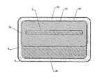
しかしながら、有利な実施形態では、図7に示す電極配列が用いられる。この図では、ハッチングを施された領域は、絶縁層5aによって覆われた領域に対応し、点を付された領域は、電極5、6により覆われた領域に対応する。 However, in an advantageous embodiment, the electrode arrangement shown in FIG. 7 is used. In this figure, the hatched area corresponds to the area covered with the insulating
図から分かるように、外側電極6は、ストリップ電極5に実質的に平行な2つの水平部6a、6bを有する長方形状である。部分6bは、部分6aよりも幅が広い。外側電極6の内部の縁6cは、実質的に長方形の中央領域50を囲む。ストリップ電極5は、中央領域50の実質的に中央に配置される。 As can be seen from the figure, the outer electrode 6 has a rectangular shape having two
絶縁層5aは、中央領域50の実質的に全て、および外側電極6の幅広の水平部6bの一部を覆う。 The insulating
検体と接触する可能性のある、電極のあらゆる表面は、金、または生物学的に最良な互換性であるための他の貴金属であるべきである。図7の実施形態では、少なくとも外側電極6は、有利な形態としては、金の層によって覆われている。 Any surface of the electrode that may come into contact with the analyte should be gold or other noble metal to be the best biologically compatible. In the embodiment of FIG. 7, at least the outer electrode 6 is advantageously covered by a gold layer.
同じ理由により、少なくとも絶縁層5aによって覆われていないスルーコンタクト10は、ガラス、セラミック、プラスチック、貴金属の層または他の生物学上、不活性な金属で覆われているべきである。よって、図1の実施形態では、スルーコンタクト10は、ガラス51の粒によって覆われている。 For the same reason, the through
注記
上記の説明では、共振回路35の両端の電圧は、入力u1において測定された。しかしながら、電極配列のインピーダンスに依存する他の電圧または電流を測定することも可能であることに留意されなければならない。具体的には、共振回路35の両端の電圧の代わりに抵抗R1またはインダクタンスL1の両端の電圧効果を測定することが可能である。Note In the above description, the voltage across the
あらゆる場合において、処理回路37、38は、電極配列の、印加された電気信号への応答を測定する必要がある。すなわち、測定された値は、電極における検体の誘電特性に依存している必要がある。 In all cases, the
また、共振回路35は、インダクタンスに直列に配置されたキャパシタを有する代わりに、インダクタンスと並列なキャパシタによって実現されてもよい。 Further, the
最後に、図1、図7に示す電極配列は、様々な可能な実施形態のうちの1つに過ぎない。例えば、外側電極6は、本装置の電極面に達する装置100の(金属の)筐体1の一部によって置換されてもよい。この場合、金属の筐体1は、電極配列の一部を構成する。 Finally, the electrode arrangement shown in FIGS. 1 and 7 is only one of various possible embodiments. For example, the outer electrode 6 may be replaced by a part of the (metal)
本発明の好ましい実施形態が本明細書において示されまた記載されたが、本発明はこれらに限定されず、請求の範囲の範疇内で他の様々な形態で実現され且つ実施され得ることに留意されなくてはならない。 While preferred embodiments of the invention have been shown and described herein, it should be noted that the invention is not so limited and can be implemented and implemented in various other forms within the scope of the claims. It must be done.
Claims (8)
Translated fromJapanese前記組織に付するための電極配列(5、6)と、
前記電極配列(5、6)に印加される所定の周波数範囲内のAC電圧(VVCO)を生成するための電圧制御発振器(31)と、
前記組織の誘電特性に応じた前記電極配列(5、6)の応答を測定するための処理回路(37、38)と、
を具備し、前記電圧制御発振器(31)は、
増幅率に影響を与える増幅率制御信号(V2)のための入力を有する2つの増幅器(T1、T2)と、
前記電圧制御発振器(31)の動作の周波数を決定する周波数制御信号(V1)のための入力を有する2つの電圧制御キャパシタ(D1、D2)を具備する2つのタンク回路(L1、D1、L2、D2)と、
を具備し、
前記装置は、前記少なくとも1つの電圧制御キャパシタ(D1、D2)の両端のDC電圧がゼロに近いとき前記増幅率を増加させるために前記増幅率制御信号(V2)を制御するよう適合されている、装置。A device for measuring properties of living tissue, in particular glucose levels of said tissue,
An electrode array (5, 6) for attaching to the tissue;
A voltage controlled oscillator (31) for generating an AC voltage (VVCO ) within a predetermined frequency range applied to the electrode arrangement (5, 6);
A processing circuit (37, 38) for measuring the response of the electrode arrangement (5, 6) according to the dielectric properties of the tissue;
The voltage controlled oscillator (31) includes:
Two amplifiersthat have a input for amplification factor control signal to influence the amplification factor (V2) and (T1, T2),
Said voltage controlled oscillator (31)Two of the tank circuit (L1,you comprisestwo voltage controlled capacitors (D1, D2)that have a input for frequency control signal which determines the frequency of operation of the (V1) D1 , L2, D2),
Comprising
The apparatus is adapted to control the gain control signal (V2) to increase the gain when the DC voltage across the at least one voltage control capacitor (D1, D2) is near zero. ,apparatus.
Applications Claiming Priority (2)
| Application Number | Priority Date | Filing Date | Title |
|---|---|---|---|
| CH0300795 | 2003-12-02 | ||
| PCT/CH2004/000077WO2005053523A1 (en) | 2003-12-02 | 2004-02-10 | A device and method for measuring a property of living tissue |
Related Child Applications (1)
| Application Number | Title | Priority Date | Filing Date |
|---|---|---|---|
| JP2010044597ADivisionJP2010188135A (en) | 2003-12-02 | 2010-03-01 | Device and method for measuring characteristics of living tissue |
Publications (2)
| Publication Number | Publication Date |
|---|---|
| JP2007514474A JP2007514474A (en) | 2007-06-07 |
| JP4532502B2true JP4532502B2 (en) | 2010-08-25 |
Family
ID=34638002
Family Applications (2)
| Application Number | Title | Priority Date | Filing Date |
|---|---|---|---|
| JP2006541776AExpired - LifetimeJP4532502B2 (en) | 2003-12-02 | 2004-02-10 | A device for measuring the characteristics of living tissue |
| JP2010044597APendingJP2010188135A (en) | 2003-12-02 | 2010-03-01 | Device and method for measuring characteristics of living tissue |
Family Applications After (1)
| Application Number | Title | Priority Date | Filing Date |
|---|---|---|---|
| JP2010044597APendingJP2010188135A (en) | 2003-12-02 | 2010-03-01 | Device and method for measuring characteristics of living tissue |
Country Status (5)
| Country | Link |
|---|---|
| US (1) | US8197406B2 (en) |
| EP (1) | EP1694197B1 (en) |
| JP (2) | JP4532502B2 (en) |
| AT (1) | ATE531309T1 (en) |
| WO (1) | WO2005053523A1 (en) |
Families Citing this family (25)
| Publication number | Priority date | Publication date | Assignee | Title |
|---|---|---|---|---|
| EP1768545B1 (en) | 2004-06-07 | 2009-06-10 | Solianis Holding AG | A method and device for determining a parameter of living tissue |
| US7951357B2 (en) | 2004-07-14 | 2011-05-31 | Glusense Ltd. | Implantable power sources and sensors |
| EP1954175B1 (en)* | 2005-11-10 | 2016-07-13 | Biovotion AG | Device for determining the glucose level in body tissue |
| TW200734462A (en) | 2006-03-08 | 2007-09-16 | In Motion Invest Ltd | Regulating stem cells |
| US20100240977A1 (en) | 2007-06-20 | 2010-09-23 | Andreas Caduff | Method for measuring the response of a tissue to an electromagnetic field |
| JP2011509127A (en)* | 2008-01-11 | 2011-03-24 | ソリアニス・ホールディング・アーゲー | Method and apparatus for determining characteristics of biological tissue |
| US20090270756A1 (en)* | 2008-04-23 | 2009-10-29 | Gamache Ronald W | Determining physiological characteristics of animal |
| WO2009152624A1 (en)* | 2008-06-18 | 2009-12-23 | Solianis Holding Ag | Device and method for determining at least one characterizing parameter of multilayer body tissue |
| WO2010118537A1 (en)* | 2009-04-17 | 2010-10-21 | Solianis Holding Ag | Sensing device for body tissue properties |
| JP5628289B2 (en)* | 2009-04-17 | 2014-11-19 | バイオボーション・アーゲーBiovotion AG | Broadband field response measurement for glucose determination |
| CN102575997B (en) | 2009-06-09 | 2014-12-17 | 生物传感器股份有限公司 | Non-invasive monitoring of blood metabolite levels |
| KR101207750B1 (en) | 2010-12-06 | 2012-12-04 | 성균관대학교산학협력단 | Corrosion estimation kit of biodegradable magnesium alloys and corrosion estimation method of biodegradable magnesium alloys used thereof |
| US9037205B2 (en) | 2011-06-30 | 2015-05-19 | Glusense, Ltd | Implantable optical glucose sensing |
| US10875274B2 (en) | 2011-11-29 | 2020-12-29 | Columbia Sportswear North America, Inc. | Cooling material |
| CN102788825B (en)* | 2012-07-29 | 2014-07-30 | 江苏大学 | Blood glucose detecting method and blood glucometer |
| US9417105B2 (en)* | 2012-12-21 | 2016-08-16 | Agamatrix, Inc. | Integrators for sensor applications |
| CN106999118B (en) | 2014-10-13 | 2020-07-17 | 葡萄糖传感器公司 | Analyte sensing device |
| JP6416398B2 (en)* | 2015-07-13 | 2018-10-31 | シャープ株式会社 | Sensor circuit |
| JP6556568B2 (en)* | 2015-09-09 | 2019-08-07 | シャープ株式会社 | Sensor device |
| US10871487B2 (en) | 2016-04-20 | 2020-12-22 | Glusense Ltd. | FRET-based glucose-detection molecules |
| KR102844442B1 (en) | 2019-04-12 | 2025-08-07 | 삼성전자주식회사 | Apparatus and method for analyzing composition in body, and impedance measuring apparatus |
| KR20210120174A (en) | 2020-03-25 | 2021-10-07 | 삼성전자주식회사 | Apparatus and method for analyzing composition in body, and impedance measuring apparatus |
| KR20220156197A (en)* | 2021-05-18 | 2022-11-25 | 주식회사 에스비솔루션 | Method and system for detecting analyte concentration from relative permittivity change of bio-tissue in living body |
| US20230134523A1 (en)* | 2021-11-04 | 2023-05-04 | Cirrus Logic International Semiconductor Ltd. | Measurement circuitry |
| KR20250003478A (en) | 2022-01-13 | 2025-01-07 | 카나리 메디컬 스위절란트 아게 | Analytical and environmental sensors |
Family Cites Families (69)
| Publication number | Priority date | Publication date | Assignee | Title |
|---|---|---|---|---|
| US3482167A (en)* | 1967-06-12 | 1969-12-02 | Rca Corp | Automatic gain control system employing multiple insulated gate field effect transistor |
| US3803828A (en)* | 1972-10-12 | 1974-04-16 | Timex Corp | Resistor trim for quartz oscillator |
| ATA395075A (en) | 1975-05-23 | 1978-03-15 | Blum Gmbh Julius | Method and apparatus for the quantitative determination of elements and substances in aqueous solutions |
| FR2387659A1 (en) | 1977-04-21 | 1978-11-17 | Armines | GLYCEMIA CONTROL AND REGULATION DEVICE |
| GB2033575B (en) | 1978-05-24 | 1983-03-02 | Rolfe P | Investigating substances in a patient's bloodstream |
| GB2100864B (en) | 1978-05-24 | 1983-06-02 | Peter Rolfe | Investigating substances in bloodstream and detecting blood flow |
| GB2055206B (en)* | 1979-07-31 | 1983-11-16 | Yeda Res & Dev | Detection of tumors |
| DE3017168A1 (en) | 1980-05-05 | 1981-11-12 | Yeda Research And Development Co. Ltd., Rehovot | Tumour detector esp. for breast cancer - has processor coupled to balancing bridge for indicating dielectric constant of localised region of breast tissue (IL 31.1.80) |
| US4509531A (en)* | 1982-07-28 | 1985-04-09 | Teledyne Industries, Inc. | Personal physiological monitor |
| GB8408529D0 (en) | 1984-04-03 | 1984-05-16 | Health Lab Service Board | Concentration of biological particles |
| DE3623711A1 (en)* | 1985-07-12 | 1987-01-15 | Med & Tech Handels Gmbh | Device for the determination of properties, variations and changes of the human or animal body |
| US4765179A (en)* | 1985-09-09 | 1988-08-23 | Solid State Farms, Inc. | Radio frequency spectroscopy apparatus and method using multiple frequency waveforms |
| US4679426A (en)* | 1985-09-09 | 1987-07-14 | Fuller Milton E | Wave shape chemical analysis apparatus and method |
| JPS6283649A (en) | 1985-10-08 | 1987-04-17 | Matsushita Electric Ind Co Ltd | blood sugar meter |
| WO1987006553A1 (en) | 1986-04-30 | 1987-11-05 | Kabushiki Kaisha Komatsu Seisakusho | Steering system |
| US4875486A (en)* | 1986-09-04 | 1989-10-24 | Advanced Techtronics, Inc. | Instrument and method for non-invasive in vivo testing for body fluid constituents |
| AT395075B (en) | 1986-12-17 | 1992-09-10 | Chira Irvin Sorin Dipl Ing | METHOD AND DEVICE FOR QUANTITATIVE DETERMINATION OF ELEMENTS AND SUBSTANCES IN AQUEOUS SOLUTIONS |
| EP0298441B1 (en) | 1987-07-06 | 1993-10-27 | Handelsgesellschaft Für Medizin Und Technik Mit Beschränkter Haftung | Device for the determination of characteristics, differences and changes in the human or animal body |
| US4751476A (en) | 1987-09-21 | 1988-06-14 | Fisher Scientific Company | Detector device and method for distinguishing between fluids having different dielectric properties |
| US5077476A (en)* | 1990-06-27 | 1991-12-31 | Futrex, Inc. | Instrument for non-invasive measurement of blood glucose |
| US5050612A (en)* | 1989-09-12 | 1991-09-24 | Matsumura Kenneth N | Device for computer-assisted monitoring of the body |
| SU1698724A1 (en) | 1989-10-26 | 1991-12-15 | Институт Радиотехники И Электроники Ан Ссср | Method of analysis of liquid dielectrics |
| GB9204689D0 (en) | 1992-03-04 | 1992-04-15 | Univ Wales | Analytical method & apparatus |
| US5212817A (en)* | 1990-09-14 | 1993-05-18 | Atkinson Noel D | Ultra high speed scan system |
| SE466987B (en)* | 1990-10-18 | 1992-05-11 | Stiftelsen Ct Foer Dentaltekni | DEVICE FOR DEEP-SELECTIVE NON-INVASIVE, LOCAL SEATING OF ELECTRICAL IMPEDANCE IN ORGANIC AND BIOLOGICAL MATERIALS AND PROBE FOR SEATING ELECTRICAL IMPEDANCE |
| EP0630471A1 (en) | 1992-03-10 | 1994-12-28 | BARNS, Christopher | Apparatus for determining the physical and/or chemical properties of a sample, particularly of blood |
| RU2069863C1 (en) | 1992-06-18 | 1996-11-27 | Центральный научно-исследовательский институт машиностроения | Analyzer of gas, liquid and loose media |
| RU2073242C1 (en) | 1993-01-01 | 1997-02-10 | Виктор Иванович Леднев | Method for indication of sugar content in blood and device for its embodiment |
| RU2088927C1 (en) | 1993-04-01 | 1997-08-27 | Ламбров Владимир Васильевич | Method and device for controlling sugar quantity in human blood in cases of diabetes mellitus |
| US5508203A (en) | 1993-08-06 | 1996-04-16 | Fuller; Milton E. | Apparatus and method for radio frequency spectroscopy using spectral analysis |
| US5792668A (en)* | 1993-08-06 | 1998-08-11 | Solid State Farms, Inc. | Radio frequency spectral analysis for in-vitro or in-vivo environments |
| DE4440224A1 (en)* | 1994-11-10 | 1996-05-15 | Pacesetter Ab | Method of manufacturing a sensor electrode |
| DE4446346A1 (en) | 1994-12-23 | 1996-06-27 | Ulrich Dr Warnke | Detecting volume changes of electrolytes esp. blood or lymph fluid in living body parts |
| US5752512A (en)* | 1995-05-10 | 1998-05-19 | Massachusetts Institute Of Technology | Apparatus and method for non-invasive blood analyte measurement |
| JPH09201337A (en) | 1996-01-25 | 1997-08-05 | Casio Comput Co Ltd | Glucose measuring device |
| US6517482B1 (en)* | 1996-04-23 | 2003-02-11 | Dermal Therapy (Barbados) Inc. | Method and apparatus for non-invasive determination of glucose in body fluids |
| US5890489A (en)* | 1996-04-23 | 1999-04-06 | Dermal Therapy (Barbados) Inc. | Method for non-invasive determination of glucose in body fluids |
| WO1998009566A1 (en) | 1996-09-09 | 1998-03-12 | International Diagnostics Technologies Inc. | Photonic molecular probe |
| US5804967A (en)* | 1996-11-15 | 1998-09-08 | The United States Of America As Represented By The Secretary Of The Navy | Apparatus and method for generating short pulses for NMR and NQR processing |
| EP1011426A1 (en)* | 1997-02-26 | 2000-06-28 | Diasense, Inc. | Individual calibration of blood glucose for supporting noninvasive self-monitoring blood glucose |
| US6028433A (en)* | 1997-05-14 | 2000-02-22 | Reid Asset Management Company | Portable fluid screening device and method |
| US6182504B1 (en)* | 1997-11-03 | 2001-02-06 | Roxar, Inc. | Emulsion composition monitor |
| AU762922B2 (en) | 1998-02-04 | 2003-07-10 | Dermal Therapy (Barbados) Inc. | Method and apparatus for non-invasive determination of glucose in body fluids |
| SE512047C2 (en) | 1998-03-02 | 2000-01-17 | John Jacob Engellau | Measuring device, especially for blood sugar determination |
| US6175752B1 (en)* | 1998-04-30 | 2001-01-16 | Therasense, Inc. | Analyte monitoring device and methods of use |
| DE69910003T2 (en)* | 1998-05-13 | 2004-04-22 | Cygnus, Inc., Redwood City | MONITORING PHYSIOLOGICAL ANALYSIS |
| WO1999058050A1 (en)* | 1998-05-13 | 1999-11-18 | Cygnus, Inc. | Signal processing for measurement of physiological analytes |
| AU5474699A (en) | 1998-08-10 | 2000-03-06 | Solid State Farms, Inc. | Improving radio frequency spectral analysis for in-vitro or in-vivo environments |
| JP2000162176A (en) | 1998-09-22 | 2000-06-16 | Omron Corp | Measuring method and measuring device using biosensor |
| GB9901304D0 (en) | 1999-01-22 | 1999-03-10 | Univ Liverpool | Apparatus and method for determining dielectric properties of an electrically conductive fluid |
| EP1092386A1 (en) | 1999-10-13 | 2001-04-18 | Süsstrunk Anita | Method and device for determining the concentration of a substance in blood |
| FI111298B (en) | 1999-11-16 | 2003-06-30 | Delfin Technologies Ltd | Method for measuring skin moisture and device for applying the method |
| DE60040483D1 (en) | 1999-12-28 | 2008-11-20 | Pindi Products Inc | METHOD AND DEVICE FOR NON-INVASIVE ANALYSIS OF BLOOD GLUCOSE |
| DE10035415A1 (en) | 2000-07-20 | 2002-01-31 | Precisa Technologies Ltd Ag Zu | Non-invasive determination of blood sugar comprises applying electric field to blood sample, switching off field, evaluating change in dielectric polarization of molecules with time and calculating the concentration of substance |
| AU2001276985A1 (en)* | 2000-07-20 | 2002-02-05 | Paratek Microwave, Inc. | Voltage controlled oscillators including tunable dielectric devices |
| CA2408338C (en)* | 2000-08-18 | 2009-09-08 | Cygnus, Inc. | Methods and devices for prediction of hypoglycemic events |
| JP3473581B2 (en)* | 2000-12-28 | 2003-12-08 | 株式会社村田製作所 | Resonant power supply circuit |
| KR20030031894A (en)* | 2001-02-05 | 2003-04-23 | 글루코센스 인코퍼레이티드 | Methods of determining concentration of glucose in blood |
| US6985702B2 (en)* | 2001-02-23 | 2006-01-10 | Koninklijke Philips Electronics N.V. | Transceiver with frequency multiplier tracked to frequency generator |
| ATE547045T1 (en)* | 2001-03-06 | 2012-03-15 | Solianis Holding Ag | DEVICE FOR DETERMINING THE CONCENTRATION OF A SUBSTANCE IN BODY FLUID |
| US7315767B2 (en)* | 2001-03-06 | 2008-01-01 | Solianis Holding Ag | Impedance spectroscopy based systems and methods |
| GB0106250D0 (en)* | 2001-03-13 | 2001-05-02 | Hall Effect Technologies Ltd | Apparatus and method for analysing blood |
| DE10119527A1 (en)* | 2001-04-12 | 2002-11-07 | Sitec Sensortechnik Gmbh | Method for the mobile or stationary acquisition of body function and metabolic data of a living body and device for carrying out the method |
| GB0110313D0 (en)* | 2001-04-27 | 2001-06-20 | Hall Effect Technologies Ltd | Apparatus and method for analysing a fluid |
| IL143904A0 (en)* | 2001-06-21 | 2002-04-21 | Glucon Inc | Method and apparatus for measuring temperature |
| JP2005500116A (en) | 2001-08-24 | 2005-01-06 | グルコセンス、インコーポレイテッド | Biosignal sensor and apparatus for recording a biosignal incorporating an application associated with the sensor |
| JP4036636B2 (en)* | 2001-11-26 | 2008-01-23 | アジレント・テクノロジーズ・インク | Phase-locked-loop oscillator with a function to compensate for the loop gain |
| US7020508B2 (en)* | 2002-08-22 | 2006-03-28 | Bodymedia, Inc. | Apparatus for detecting human physiological and contextual information |
| JP4467263B2 (en)* | 2002-09-20 | 2010-05-26 | 日本精密測器株式会社 | Electronic device for health index measurement and control method thereof |
- 2004
- 2004-02-10WOPCT/CH2004/000077patent/WO2005053523A1/enactiveApplication Filing
- 2004-02-10JPJP2006541776Apatent/JP4532502B2/ennot_activeExpired - Lifetime
- 2004-02-10USUS10/580,209patent/US8197406B2/enactiveActive
- 2004-02-10EPEP04709566Apatent/EP1694197B1/ennot_activeExpired - Lifetime
- 2004-02-10ATAT04709566Tpatent/ATE531309T1/enactive
- 2010
- 2010-03-01JPJP2010044597Apatent/JP2010188135A/enactivePending
Also Published As
| Publication number | Publication date |
|---|---|
| JP2010188135A (en) | 2010-09-02 |
| ATE531309T1 (en) | 2011-11-15 |
| EP1694197A1 (en) | 2006-08-30 |
| US8197406B2 (en) | 2012-06-12 |
| JP2007514474A (en) | 2007-06-07 |
| US20100099960A1 (en) | 2010-04-22 |
| WO2005053523A1 (en) | 2005-06-16 |
| EP1694197B1 (en) | 2011-11-02 |
Similar Documents
| Publication | Publication Date | Title |
|---|---|---|
| JP4532502B2 (en) | A device for measuring the characteristics of living tissue | |
| US9844404B2 (en) | Electrosurgical generator | |
| US6472888B2 (en) | Bioelectrical impedance measuring apparatus constructed by one-chip integrated circuit | |
| JP4499787B2 (en) | Method and apparatus for determining parameters of biological tissue | |
| US20120220886A1 (en) | Method and Apparatus for Measuring Blood Volume | |
| JP3907353B2 (en) | Bioimpedance measurement device | |
| US8099250B2 (en) | Impedance parameter values | |
| US6631292B1 (en) | Bio-electrical impedance analyzer | |
| US20040133092A1 (en) | Wireless system for measuring distension in flexible tubes | |
| Masud et al. | Measurement techniques and challenges of wireless LC resonant sensors: A review | |
| RU2088927C1 (en) | Method and device for controlling sugar quantity in human blood in cases of diabetes mellitus | |
| Pichorim et al. | A novel method to read remotely resonant passive sensors in biotelemetric systems | |
| CN112089418A (en) | Thoracic cavity electrical impedance detection method based on human tissue conductivity frequency conversion amplitude modulation method | |
| RU2366360C1 (en) | Device to measure biological fabric impedance | |
| JP5802748B2 (en) | Determination of organizational indicators | |
| US20100001803A1 (en) | Electronic circuit for obtaining a variable capacitative impedence | |
| Heller et al. | Auto-tuned induction coil conductivity sensor for in-vivo human tissue measurements | |
| Yeh et al. | Optical probe for input-impedance measurement of in vivo power-receiving microstructure | |
| Tamez et al. | Polyvinylidene Fluoride (PVDF) piezoelectric for intravascular monitoring of blood pressure and arterial blood flow rate | |
| Segura-Quijano et al. | Fully-Integrated wireless CMOS smart sensor |
Legal Events
| Date | Code | Title | Description |
|---|---|---|---|
| A621 | Written request for application examination | Free format text:JAPANESE INTERMEDIATE CODE: A621 Effective date:20061221 | |
| A131 | Notification of reasons for refusal | Free format text:JAPANESE INTERMEDIATE CODE: A131 Effective date:20091027 | |
| A601 | Written request for extension of time | Free format text:JAPANESE INTERMEDIATE CODE: A601 Effective date:20100125 | |
| A602 | Written permission of extension of time | Free format text:JAPANESE INTERMEDIATE CODE: A602 Effective date:20100201 | |
| A521 | Request for written amendment filed | Free format text:JAPANESE INTERMEDIATE CODE: A523 Effective date:20100301 | |
| TRDD | Decision of grant or rejection written | ||
| A01 | Written decision to grant a patent or to grant a registration (utility model) | Free format text:JAPANESE INTERMEDIATE CODE: A01 Effective date:20100511 | |
| A01 | Written decision to grant a patent or to grant a registration (utility model) | Free format text:JAPANESE INTERMEDIATE CODE: A01 | |
| A61 | First payment of annual fees (during grant procedure) | Free format text:JAPANESE INTERMEDIATE CODE: A61 Effective date:20100610 | |
| R150 | Certificate of patent or registration of utility model | Ref document number:4532502 Country of ref document:JP Free format text:JAPANESE INTERMEDIATE CODE: R150 Free format text:JAPANESE INTERMEDIATE CODE: R150 | |
| FPAY | Renewal fee payment (event date is renewal date of database) | Free format text:PAYMENT UNTIL: 20130618 Year of fee payment:3 | |
| FPAY | Renewal fee payment (event date is renewal date of database) | Free format text:PAYMENT UNTIL: 20130618 Year of fee payment:3 | |
| S111 | Request for change of ownership or part of ownership | Free format text:JAPANESE INTERMEDIATE CODE: R313113 | |
| FPAY | Renewal fee payment (event date is renewal date of database) | Free format text:PAYMENT UNTIL: 20130618 Year of fee payment:3 | |
| R350 | Written notification of registration of transfer | Free format text:JAPANESE INTERMEDIATE CODE: R350 | |
| R250 | Receipt of annual fees | Free format text:JAPANESE INTERMEDIATE CODE: R250 | |
| R250 | Receipt of annual fees | Free format text:JAPANESE INTERMEDIATE CODE: R250 | |
| R250 | Receipt of annual fees | Free format text:JAPANESE INTERMEDIATE CODE: R250 | |
| R250 | Receipt of annual fees | Free format text:JAPANESE INTERMEDIATE CODE: R250 | |
| R250 | Receipt of annual fees | Free format text:JAPANESE INTERMEDIATE CODE: R250 | |
| R250 | Receipt of annual fees | Free format text:JAPANESE INTERMEDIATE CODE: R250 | |
| R250 | Receipt of annual fees | Free format text:JAPANESE INTERMEDIATE CODE: R250 | |
| R250 | Receipt of annual fees | Free format text:JAPANESE INTERMEDIATE CODE: R250 | |
| S111 | Request for change of ownership or part of ownership | Free format text:JAPANESE INTERMEDIATE CODE: R313113 | |
| S531 | Written request for registration of change of domicile | Free format text:JAPANESE INTERMEDIATE CODE: R313531 | |
| R350 | Written notification of registration of transfer | Free format text:JAPANESE INTERMEDIATE CODE: R350 | |
| R250 | Receipt of annual fees | Free format text:JAPANESE INTERMEDIATE CODE: R250 | |
| R250 | Receipt of annual fees | Free format text:JAPANESE INTERMEDIATE CODE: R250 | |
| R250 | Receipt of annual fees | Free format text:JAPANESE INTERMEDIATE CODE: R250 | |
| EXPY | Cancellation because of completion of term |