JP4532129B2 - Orthopedic unicompartmental knee implant - Google Patents
Orthopedic unicompartmental knee implantDownload PDFInfo
- Publication number
- JP4532129B2 JP4532129B2JP2004026944AJP2004026944AJP4532129B2JP 4532129 B2JP4532129 B2JP 4532129B2JP 2004026944 AJP2004026944 AJP 2004026944AJP 2004026944 AJP2004026944 AJP 2004026944AJP 4532129 B2JP4532129 B2JP 4532129B2
- Authority
- JP
- Japan
- Prior art keywords
- tibial tray
- bearing component
- orthopedic
- tab portion
- component
- Prior art date
- Legal status (The legal status is an assumption and is not a legal conclusion. Google has not performed a legal analysis and makes no representation as to the accuracy of the status listed.)
- Expired - Fee Related
Links
- 0*CC1=CC=CC1=CChemical compound*CC1=CC=CC1=C0.000description1
Images


Classifications
- A—HUMAN NECESSITIES
- A61—MEDICAL OR VETERINARY SCIENCE; HYGIENE
- A61F—FILTERS IMPLANTABLE INTO BLOOD VESSELS; PROSTHESES; DEVICES PROVIDING PATENCY TO, OR PREVENTING COLLAPSING OF, TUBULAR STRUCTURES OF THE BODY, e.g. STENTS; ORTHOPAEDIC, NURSING OR CONTRACEPTIVE DEVICES; FOMENTATION; TREATMENT OR PROTECTION OF EYES OR EARS; BANDAGES, DRESSINGS OR ABSORBENT PADS; FIRST-AID KITS
- A61F2/00—Filters implantable into blood vessels; Prostheses, i.e. artificial substitutes or replacements for parts of the body; Appliances for connecting them with the body; Devices providing patency to, or preventing collapsing of, tubular structures of the body, e.g. stents
- A61F2/02—Prostheses implantable into the body
- A61F2/30—Joints
- A61F2/38—Joints for elbows or knees
- A61F2/3868—Joints for elbows or knees with sliding tibial bearing
- A—HUMAN NECESSITIES
- A61—MEDICAL OR VETERINARY SCIENCE; HYGIENE
- A61F—FILTERS IMPLANTABLE INTO BLOOD VESSELS; PROSTHESES; DEVICES PROVIDING PATENCY TO, OR PREVENTING COLLAPSING OF, TUBULAR STRUCTURES OF THE BODY, e.g. STENTS; ORTHOPAEDIC, NURSING OR CONTRACEPTIVE DEVICES; FOMENTATION; TREATMENT OR PROTECTION OF EYES OR EARS; BANDAGES, DRESSINGS OR ABSORBENT PADS; FIRST-AID KITS
- A61F2/00—Filters implantable into blood vessels; Prostheses, i.e. artificial substitutes or replacements for parts of the body; Appliances for connecting them with the body; Devices providing patency to, or preventing collapsing of, tubular structures of the body, e.g. stents
- A61F2/02—Prostheses implantable into the body
- A61F2/30—Joints
- A61F2/38—Joints for elbows or knees
- A61F2002/3895—Joints for elbows or knees unicompartimental
Landscapes
- Health & Medical Sciences (AREA)
- Orthopedic Medicine & Surgery (AREA)
- Heart & Thoracic Surgery (AREA)
- Vascular Medicine (AREA)
- Oral & Maxillofacial Surgery (AREA)
- Transplantation (AREA)
- Engineering & Computer Science (AREA)
- Biomedical Technology (AREA)
- Physical Education & Sports Medicine (AREA)
- Cardiology (AREA)
- Life Sciences & Earth Sciences (AREA)
- Animal Behavior & Ethology (AREA)
- General Health & Medical Sciences (AREA)
- Public Health (AREA)
- Veterinary Medicine (AREA)
- Prostheses (AREA)
- Materials For Medical Uses (AREA)
Description
Translated fromJapanese本発明は、可動ベアリングと一般に呼称されるタイプの人工膝関節インプラントに関する。より詳細には、本発明は、ユニコンパートメント(”ユニ”)人工膝関節において使用するための可動ベアリング型人工膝関節に関する。 The present invention relates to a knee prosthesis implant of the type commonly referred to as a movable bearing. More particularly, the present invention relates to a movable bearing type knee prosthesis for use in a unicompartmental (“uni”) knee prosthesis.
人の膝関節の屈曲及び伸展の際に固定の脛骨トレイに対して可動になっているベアリングコンポーネント(軸受コンポーネント)を有した人工膝関節は、可動ベアリング(モービルベアリング)型人工膝関節として知られており、本願中でも可動ベアリング型人工膝関節と呼称する。可動ベアリング型人工膝関節は、一般に、前処置を施された近位脛骨に取り付けられた脛骨トレイと、典型的には超高分子量ポリエチレン(“UHMWPE”)からなるベアリングコンポーネントとから構成される。ベアリングコンポーネントは、大腿骨コンポーネントがベアリングコンポーネントに対して関節動作できるように構成されている。多くの場合、膝関節の運動の際に脛骨コンポーネントに対するベアリングコンポーネントの運動を限定又は制限するために、単数又は複数の機構が存在している。 A knee prosthesis with a bearing component that is movable relative to a fixed tibial tray during flexion and extension of a human knee joint is known as a mobile bearing type knee prosthesis. It is also called a movable bearing type artificial knee joint in the present application. Movable bearing knee prostheses are generally composed of a tibial tray attached to a pretreated proximal tibia and a bearing component typically made of ultra high molecular weight polyethylene ("UHMWPE"). The bearing component is configured to allow the femoral component to articulate relative to the bearing component. In many cases, one or more mechanisms exist to limit or limit the movement of the bearing component relative to the tibial component during knee joint movement.
近年、膝関節置換術のような整形外科手術をより少ない又は最小の侵襲で行うことが、医師の目標となってきている。このため、整形外科医は、患者の膝関節の一つの区画(コンパートメント)のみに疾患又は損傷がある状況では、ユニ膝関節置換術を行い始めている。膝関節部分置換術によれば、膝関節の非患部区画に外傷を生じさせることが回避される。さらに、ユニ膝関節インプラントは全膝関節インプラントよりも小さい。よって、膝関節部分置換術は、当然に、膝関節全置換術より侵襲が少なくなる。しかしながら、ユニ人工膝関節は膝関節全置換術における対応物と比較して周知度に劣るので、可動ベアリング型ユニ人工膝関節のための設計はあったとしてもほとんど存在しない。 In recent years, it has become a goal of physicians to perform orthopedic surgery such as knee replacement with less or minimal invasiveness. For this reason, orthopedic surgeons are beginning to perform uni-knee replacement in situations where only one compartment (compartment) of the patient's knee joint is diseased or damaged. According to the knee joint partial replacement, it is possible to avoid causing trauma to the non-affected section of the knee joint. Furthermore, uni knee implants are smaller than full knee implants. Therefore, the knee joint partial replacement is naturally less invasive than the total knee replacement. However, since uni-artificial knee joints are less well known than their counterparts in total knee arthroplasty, there are few, if any, designs for movable bearing uni-artificial knee joints.
本発明は、一つの実施形態において、外縁部に複数のタブが設けられた上側表面を含む脛骨トレイと、大腿骨側人工膝関節と関節動作可能に係合するように構成された上側表面と周方向に延びる周方向溝とを有し且つ脛骨トレイの上側表面上に配設されたベアリングコンポーネントとを有し、脛骨トレイのタブが環状溝と係合し、ベアリングコンポーネントが、傾きを生じたり脱臼に至ったりすることなく、脛骨トレイに対して移動できるように協働する、人間の膝関節の単一の区画内に移植するための整形外科用膝関節コンポーネントからなる。 The present invention, in one embodiment, includes a tibial tray including an upper surface provided with a plurality of tabs on an outer edge, and an upper surface configured to operatively engage a femoral prosthetic knee joint; A circumferentially extending circumferential groove and a bearing component disposed on the upper surface of the tibial tray, the tab of the tibial tray engaging the annular groove, It consists of an orthopedic knee joint component for implantation within a single compartment of a human knee joint that cooperates to move relative to the tibial tray without leading to dislocation.
本発明は、他の実施形態において、ベアリングコンポーネントと支持係合した脛骨トレイを備え、ベアリングコンポーネントが、大腿骨側人工膝関節と関節動作可能に係合するように構成された上側表面と、ベアリングコンポーネントの上側表面に沿って設けられた一対のスロットとを含むようになっている、人間の膝関節の単一の区画内に移植するための整形外科用膝関節コンポーネントからなる。大腿骨コンポーネントは関節表面から延びる一対のレールを有し、レールがスロットと摺動可能に係合して、ベアリングコンポーネントが脛骨トレイに対して移動できるようになっている。 The present invention, in another embodiment, includes a tibial tray in support engagement with a bearing component, the bearing component configured to articulatably engage a femoral prosthetic knee joint, It comprises an orthopedic knee joint component for implantation within a single compartment of a human knee joint, which includes a pair of slots provided along the upper surface of the component. The femoral component has a pair of rails extending from the articulating surface such that the rails are slidably engaged with the slots so that the bearing component can move relative to the tibial tray.
本発明の利点は、膝関節部分置換術において有益な可動ベアリング型人工膝関節を提供することである。本発明の他の利点は、以下の説明及び特許請求の範囲を読み、添付図面を見ることによって、当業者にとって明らかとなる。 An advantage of the present invention is to provide a movable bearing type knee prosthesis that is useful in partial knee arthroplasty. Other advantages of the present invention will become apparent to one of ordinary skill in the art upon reading the following description and claims, and upon viewing the accompanying drawings.
添付図面に関してなされる本発明の実施形態の以下の説明を参照することによって、本発明の上述の及び他の特徴及び目的、それらを実現する方法が明らかとなり、発明自体についてもより十分に理解される。 The foregoing and other features and objects of the invention and the manner in which they are realized will become apparent and the invention itself will be more fully understood by reference to the following description of embodiments of the invention taken in conjunction with the accompanying drawings. The
対応する参照符号は複数の図面を通して対応する部分を指している。図面は、本発明の例示の実施形態を表しているが、必ずしも正確な縮尺ではなく、本発明をより十分に図示し説明するために特定の特徴が誇張されていることがある。本願で提示されている具体例は、本発明の例示の実施形態を示しているに過ぎず、かかる具体例が本願の特許請求の範囲を制限するものではない。 Corresponding reference characters indicate corresponding parts throughout the several views. Although the drawings represent exemplary embodiments of the present invention, they are not necessarily to scale and certain features may be exaggerated in order to more fully illustrate and explain the present invention. The specific examples presented herein are merely illustrative examples of the invention, and such specific examples do not limit the scope of the claims herein.
本願で使用されている場合、以下の方向の定義が適用されるものとする。「前」、「後」は、それぞれ、身体の正面に近い側、身体の背面に近い側を意味する。したがって、本願に記載されている膝関節の場合、「前」とは、脚が伸展位になっているときの膝関節における身体の正面に近い部分を指す。「近位」、「遠位」は、それぞれ、構造の根元に近い側、構造の根元から遠い側を意味する。例えば、遠位大腿骨は膝関節の一部になっている一方、近位大腿骨は股関節に近い側である。最後に、形容詞としての「内」、「外」は、それぞれ、正中面に近い側、正中面から遠い側を意味する。正中面は、身体を右左半分に分割する身体の中央を通る仮想上の垂直面である。 As used herein, the following direction definitions shall apply: “Front” and “rear” mean the side close to the front of the body and the side close to the back of the body, respectively. Therefore, in the case of the knee joint described in the present application, “front” refers to a portion of the knee joint close to the front of the body when the leg is in the extended position. “Proximal” and “distal” mean the side close to the base of the structure and the side far from the base of the structure, respectively. For example, the distal femur is part of the knee joint, while the proximal femur is on the side close to the hip joint. Finally, “inner” and “outer” as adjectives mean the side closer to the median plane and the side farther from the median plane, respectively. The median plane is a virtual vertical plane passing through the center of the body that divides the body into right and left halves.
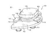
図1には、本発明の第1の実施形態によるユニ人工膝関節インプラント100の斜視図が示されている。ユニ人工膝関節インプラント100は、脛骨トレイ110と、ベアリングコンポーネント(軸受コンポーネント)160とを備えている。ユニ人工膝関節インプラント100は、障害や疾患で失った骨や組織を置換するために人間の膝関節の単一の区画(コンパートメント)内の関節空間に挿入され得る。本発明の実施形態が膝関節内側部置換術、膝関節外側部置換術、又は膝関節全置換術に有効であることは理解されよう。 FIG. 1 shows a perspective view of a uni-prosthetic
図3を参照すると、本発明の脛骨トレイ110は、上側表面120と、少なくとも二つのタブ130と、下側表面140と、脛骨トレイ110を人間の脛骨に取り付けるためのぺグ150とを備える。脛骨トレイ110は、膝関節置換術の際に形成される関節空間内に適合するような適宜の大きさのものである。脛骨トレイ110は、さらに、脛骨トレイ110が脛骨インプラントとして機能するのに必要な必須の機械的特性を有した任意の生体適合性材料から構成されることができ、かかる材料には、金属、プラスチック及びセラミックが含まれる。しかしながら、典型的には、脛骨トレイ110は、チタン合金又はコバルト合金のような生体適合性金属からなる。 Referring to FIG. 3, the
再び図3を参照すると、上側表面120は概ね平坦で滑らかとなっており、ベアリングコンポーネント160(本願において以下で説明される)が上側表面120に摺動可能に係合することを可能とさせるように構成されている。脛骨トレイ110は、上側表面120の外縁部に沿って配置された少なくとも二つのタブ130をさらに備えている。各タブ130は概略“L”字形状であり、各タブは、脛骨トレイ110の上側表面120に接続され且つ該上側表面120から上方に延びている第1のタブ部分131を備えるようになっている。各タブ130は、さらに、第1のタブ部分131の自由端部に接続され且つ該自由端部から上側表面120と概略平行となるように上側表面120の概略内側に向かって延びている第2のタブ部分132を備えている。 Referring again to FIG. 3, the
さらに図3を参照すると、脛骨トレイ110は、さらに、下側表面140を備えている。下側表面140は、外科的処置により前処置を施された近位脛骨に脛骨トレイ110を固定的に取り付けるための取付手段150を備えている。取付手段150は、近位脛骨に脛骨トレイを取り付けるために先行技術において公知となっている任意の手段とすることができる。しかしながら、近位脛骨に脛骨トレイ110を取り付ける正確な取付手段150は本発明にとって重要ではない。例えば、取付手段150は、ぺグ、ネジ、ピン、内部に骨を成長させ得る骨成長表面、脛骨の髄内腔内に挿入するための長尺ステム、またはこれらの組合せとすることができる。取付手段を骨成長表面とする場合、脛骨トレイ110の下側表面は、多孔質チタン、多孔質タンタル、FIBERMETAL(ファイバメタル)(商標)やTRABECULAR(商標)メタルのような繊維金属からなることが好ましい。 Still referring to FIG. 3, the
再び図1を参照すると、ユニ人工膝関節インプラント100は、さらに、ベアリングコンポーネント160を備えている。ベアリングコンポーネント160は、通常、超高分子量ポリエチレン(“UHMWPE”)又は高度に架橋されたUHMWPEのような熱可塑性ポリマ材料又は熱硬化性ポリマ材料から構成される。ベアリングコンポーネント160は、さらに、ユニ人工膝関節のベアリングコンポーネントとして使用されるのに適した形状及び大きさを備えている。 Referring again to FIG. 1, the
ベアリングコンポーネント160は、遠位ユニ人工大腿骨の回転及び並進関節運動に対応できるように構成された上側表面170をさらに備えている。しかしながら、上側表面170の正確な形状又はこのような遠位人工大腿骨の正確な構造は本発明の実施形態にとって重要ではない。 The
また、ベアリングコンポーネント160は、脛骨トレイ110の上側表面120に摺動可能に係合するように構成された下側表面180を備え、ベアリングコンポーネント160が脛骨トレイ110に対して動くことができるようになっている。図1〜図5に示されている実施形態では、脛骨トレイ110の上側表面120は平坦であり、ベアリングコンポーネント160は上側表面120と概略平行な平面内においていずれの方向にも移動可能となっている。 The
ベアリングコンポーネント160は、さらに、概略垂直方向に延びる円周状の壁を備えており、円周状の壁には溝190が設けられている。溝190は任意の第2のタブ部分132がそこに嵌合することを可能とさせるのに適した深さ及び高さを有している。溝190の深さ及び高さは、タブ130の第2のタブ部分132が溝190に嵌合したときに溝190の高さ方向に隙間が残り、ベアリングコンポーネント160が脛骨トレイ110の上側表面120に沿って容易に摺動できるようになっている。タブ130は、ベアリングコンポーネント160が脛骨トレイ110の上側表面120から滑り外れることを防止する。ベアリングコンポーネント160が傾くことを防止するために、タブ130のうちの少なくとも一つが溝190と係合することが望ましい。 The
図6〜図8は、本発明の第2の実施形態による人工膝関節インプラント200を示しており、人工膝関節インプラント200は大腿骨コンポーネント210と、ベアリングコンポーネント260と、脛骨トレイ290とを備えている。 6-8 illustrate a
図6を参照すると、詳細には、大腿骨コンポーネント210は、外科的処置により前処置を施された遠位大腿骨と係合するための骨接触表面220を備えている。骨接触表面220は、通常、互いに交わる複数の面と、前処置を施された遠位大腿骨に大腿骨コンポーネント210を取り付けるための取付手段とを含んでいる。これら取付手段には、圧入、ネジ、内部に骨を成長させ得る骨成長材料、支柱、又はこれらの組合せが含まれ得る。 Referring to FIG. 6, in particular, the
図6及び図7を参照すると、大腿骨コンポーネント210は、さらに、骨接触表面220と反対側に設けられた関節表面230を備えている。関節表面230は、本願において以下に記載されるようなベアリングコンポーネントに対して回転及び並進運動をし得るように、概略アーチ形状になっている。 With reference to FIGS. 6 and 7, the
図8を参照すると、大腿骨コンポーネント210は、内側縁部及び外側縁部と、各縁部に沿って配置され関節表面230から延びているレール250とをさらに備えている。レール250は以下で説明するベアリングコンポーネント260のスロット275に摺動可能に係合するように構成されている。 Referring to FIG. 8, the
続けて図6及び図8を参照すると、ベアリングコンポーネント260が示されている。ベアリングコンポーネント260はユニ人工膝関節においてベアリングコンポーネント260として使用するのに適した形状及び大きさを備えている。 With continued reference to FIGS. 6 and 8, a
ベアリングコンポーネント260は、さらに、大腿骨コンポーネントの回転及び並進関節運動に適応できるように構成された上側表面270を備えている。上側表面270の内側縁部及び外側縁部に沿って設けられたスロット275は、レール250又は大腿骨コンポーネント210を摺動可能に受容し、大腿骨コンポーネント210がベアリングコンポーネント260に対して横方向に移動できないように構成されている。 The
しかしながら、本発明の範囲内で様々なスロット及びレールの形態がとられ得ることは理解されよう。例であって、限定ではないが、本発明は、2つより少ない又は2つより多いレール及びスロットの組合せを備えることもできる。あるいはまた、レールがベアリングコンポーネント260の上側表面270に設けられ、スロットが大腿骨コンポーネント210の関節表面230に設けられることも可能である。 However, it will be understood that various slot and rail configurations may be taken within the scope of the present invention. By way of example and not limitation, the present invention may comprise fewer than two or more than two rail and slot combinations. Alternatively, rails can be provided on the
また、ベアリングコンポーネント260は、脛骨トレイ290の上側表面291と摺動可能に係合する形状の下側表面280を備え、ベアリングコンポーネント260が脛骨トレイ290に対して移動できるようになっている。図6〜図8に示されている実施形態では、脛骨トレイ290の上側表面291は平坦であり、ベアリングコンポーネント260が上側表面291と平行な平面内においてどの方向にも移動可能になっている。 The
当業者は、上記が本発明の好ましい実施形態の説明であり、特許請求の範囲に規定される本発明の範囲から逸脱することなく好ましい実施形態に対して設計及び構成上の変形を加えることができることを理解できるであろう。 Those skilled in the art have described the preferred embodiments of the present invention and are capable of making design and construction variations to the preferred embodiments without departing from the scope of the present invention as defined in the claims. You will understand what you can do.
100…人工膝関節インプラント
110…脛骨トレイ
120…上側表面
130…タブ
140…下側表面
160…ベアリングコンポーネント
170…上側表面
180…下側表面
200…人工膝関節インプラント
210…大腿骨コンポーネント
230…関節表面
250…レール
260…ベアリングコンポーネント
270…上側表面
275…スロット
280…下側表面
290…脛骨トレイ
291…上側表面DESCRIPTION OF
Claims (5)
Translated fromJapanese関節表面を有した大腿骨コンポーネントと、
少なくとも二つのタブが縁部に設けられている上側表面を有した脛骨トレイと、
前記大腿骨コンポーネントが関節動作することを可能とさせるように構成された上側表面と、前記脛骨トレイの前記上側表面と摺動可能に係合するように構成された下側表面と、周方向に延びる溝が設けられている外壁とを有するベアリングコンポーネントと、
を備え、
前記脛骨トレイの前記タブが、前記脛骨トレイの前記上側表面から近位側に向かって延びる第1のタブ部分と、前記第1のタブ部分に取り付けられており前記脛骨トレイの概略中央に向かって延びる第2のタブ部分とを有し、前記第2のタブ部分が前記ベアリングコンポーネントの外壁の溝内に係合可能となっており、
前記ベアリングコンポーネントは前記脛骨トレイの前記上側表面と概略平行な平面内においていずれの方向にも移動可能となっており、
前記溝と、少なくとも二つの前記タブの前記第2のタブ部分と、の協働により、ベアリングコンポーネントが脛骨トレイの上側表面から滑り外れることが防止されることを特徴とする、整形外科用単顆膝関節インプラント。An orthopedic unicondylar knee implant for implantation within a single compartment of a human knee joint,
A femoral component having a joint surface;
A tibial tray having an upper surface with at least two tabs provided at the edges;
An upper surface configured to allow the femoral component to articulate; a lower surface configured to slidably engage the upper surface of the tibial tray; and circumferentially A bearing component having an outer wall provided with an extending groove;
With
The tab of the tibial tray has a first tab portion extending proximally from the upper surface of the tibial tray, and is attached to the first tab portion and toward the approximate center of the tibial tray. and a second tab portion extending,has a engageablewith thesecond tab portion within the groove of the outer wall of the bearingcomponent,
The bearing component is movable in any direction within a plane generally parallel to the upper surface of the tibial tray;
And the groove, and the second tab portion of the at least two of said tabs, the cooperation of the bearing component, characterized in thatit is prevented from being disengaged from sliding upper surface of the tibialtray, orthopedic unicompartmental Knee joint implant.
Applications Claiming Priority (1)
| Application Number | Priority Date | Filing Date | Title |
|---|---|---|---|
| US10/357,264US6946001B2 (en) | 2003-02-03 | 2003-02-03 | Mobile bearing unicompartmental knee |
Publications (2)
| Publication Number | Publication Date |
|---|---|
| JP2004237096A JP2004237096A (en) | 2004-08-26 |
| JP4532129B2true JP4532129B2 (en) | 2010-08-25 |
Family
ID=32655617
Family Applications (1)
| Application Number | Title | Priority Date | Filing Date |
|---|---|---|---|
| JP2004026944AExpired - Fee RelatedJP4532129B2 (en) | 2003-02-03 | 2004-02-03 | Orthopedic unicompartmental knee implant |
Country Status (5)
| Country | Link |
|---|---|
| US (1) | US6946001B2 (en) |
| EP (1) | EP1442728A3 (en) |
| JP (1) | JP4532129B2 (en) |
| AU (1) | AU2004200328B2 (en) |
| CA (1) | CA2455382C (en) |
Families Citing this family (108)
| Publication number | Priority date | Publication date | Assignee | Title |
|---|---|---|---|---|
| US7468075B2 (en) | 2001-05-25 | 2008-12-23 | Conformis, Inc. | Methods and compositions for articular repair |
| US7618451B2 (en) | 2001-05-25 | 2009-11-17 | Conformis, Inc. | Patient selectable joint arthroplasty devices and surgical tools facilitating increased accuracy, speed and simplicity in performing total and partial joint arthroplasty |
| US8083745B2 (en) | 2001-05-25 | 2011-12-27 | Conformis, Inc. | Surgical tools for arthroplasty |
| US8882847B2 (en) | 2001-05-25 | 2014-11-11 | Conformis, Inc. | Patient selectable knee joint arthroplasty devices |
| US8556983B2 (en) | 2001-05-25 | 2013-10-15 | Conformis, Inc. | Patient-adapted and improved orthopedic implants, designs and related tools |
| US8545569B2 (en) | 2001-05-25 | 2013-10-01 | Conformis, Inc. | Patient selectable knee arthroplasty devices |
| US20030055502A1 (en) | 2001-05-25 | 2003-03-20 | Philipp Lang | Methods and compositions for articular resurfacing |
| US8735773B2 (en) | 2007-02-14 | 2014-05-27 | Conformis, Inc. | Implant device and method for manufacture |
| US8617242B2 (en) | 2001-05-25 | 2013-12-31 | Conformis, Inc. | Implant device and method for manufacture |
| US8480754B2 (en) | 2001-05-25 | 2013-07-09 | Conformis, Inc. | Patient-adapted and improved articular implants, designs and related guide tools |
| US7534263B2 (en) | 2001-05-25 | 2009-05-19 | Conformis, Inc. | Surgical tools facilitating increased accuracy, speed and simplicity in performing joint arthroplasty |
| US8771365B2 (en) | 2009-02-25 | 2014-07-08 | Conformis, Inc. | Patient-adapted and improved orthopedic implants, designs, and related tools |
| US9603711B2 (en) | 2001-05-25 | 2017-03-28 | Conformis, Inc. | Patient-adapted and improved articular implants, designs and related guide tools |
| WO2000035346A2 (en) | 1998-09-14 | 2000-06-22 | Stanford University | Assessing the condition of a joint and preventing damage |
| US7239908B1 (en) | 1998-09-14 | 2007-07-03 | The Board Of Trustees Of The Leland Stanford Junior University | Assessing the condition of a joint and devising treatment |
| ATE426357T1 (en) | 2000-09-14 | 2009-04-15 | Univ Leland Stanford Junior | ASSESSING THE CONDITION OF A JOINT AND PLANNING TREATMENT |
| DE60136474D1 (en) | 2000-09-14 | 2008-12-18 | Univ R | ASSESSMENT OF THE CONDITION OF A JOINT AND LOSS OF CARTEL TISSUE |
| US8439926B2 (en) | 2001-05-25 | 2013-05-14 | Conformis, Inc. | Patient selectable joint arthroplasty devices and surgical tools |
| US20030065397A1 (en) | 2001-08-27 | 2003-04-03 | Hanssen Arlen D. | Prosthetic implant support structure |
| US20040162619A1 (en)* | 2001-08-27 | 2004-08-19 | Zimmer Technology, Inc. | Tibial augments for use with knee joint prostheses, method of implanting the tibial augment, and associated tools |
| US7892288B2 (en) | 2001-08-27 | 2011-02-22 | Zimmer Technology, Inc. | Femoral augments for use with knee joint prosthesis |
| USD684693S1 (en) | 2002-08-22 | 2013-06-18 | Zimmer, Inc. | Prosthetic implant support structure |
| JP2006501977A (en) | 2002-10-07 | 2006-01-19 | コンフォーミス・インコーポレイテッド | Minimally invasive joint implant with a three-dimensional profile that conforms to the joint surface |
| JP2006505366A (en) | 2002-11-07 | 2006-02-16 | コンフォーミス・インコーポレイテッド | Method of determining meniscus size and shape and devised treatment |
| ES2465090T3 (en) | 2002-12-20 | 2014-06-05 | Smith & Nephew, Inc. | High performance knee prostheses |
| US7033397B2 (en)* | 2003-02-03 | 2006-04-25 | Zimmer Technology, Inc. | Mobile bearing unicondylar tibial knee prosthesis |
| US7905904B2 (en) | 2006-02-03 | 2011-03-15 | Biomet Sports Medicine, Llc | Soft tissue repair device and associated methods |
| US7909851B2 (en) | 2006-02-03 | 2011-03-22 | Biomet Sports Medicine, Llc | Soft tissue repair device and associated methods |
| US8088130B2 (en) | 2006-02-03 | 2012-01-03 | Biomet Sports Medicine, Llc | Method and apparatus for coupling soft tissue to a bone |
| US8361113B2 (en) | 2006-02-03 | 2013-01-29 | Biomet Sports Medicine, Llc | Method and apparatus for coupling soft tissue to a bone |
| US9017381B2 (en) | 2007-04-10 | 2015-04-28 | Biomet Sports Medicine, Llc | Adjustable knotless loops |
| US8128658B2 (en) | 2004-11-05 | 2012-03-06 | Biomet Sports Medicine, Llc | Method and apparatus for coupling soft tissue to bone |
| US8303604B2 (en) | 2004-11-05 | 2012-11-06 | Biomet Sports Medicine, Llc | Soft tissue repair device and method |
| US7749250B2 (en) | 2006-02-03 | 2010-07-06 | Biomet Sports Medicine, Llc | Soft tissue repair assembly and associated method |
| US8118836B2 (en) | 2004-11-05 | 2012-02-21 | Biomet Sports Medicine, Llc | Method and apparatus for coupling soft tissue to a bone |
| US8137382B2 (en) | 2004-11-05 | 2012-03-20 | Biomet Sports Medicine, Llc | Method and apparatus for coupling anatomical features |
| US8298262B2 (en) | 2006-02-03 | 2012-10-30 | Biomet Sports Medicine, Llc | Method for tissue fixation |
| US7658751B2 (en) | 2006-09-29 | 2010-02-09 | Biomet Sports Medicine, Llc | Method for implanting soft tissue |
| US20060178749A1 (en)* | 2005-02-10 | 2006-08-10 | Zimmer Technology, Inc. | Modular porous implant |
| US7601154B2 (en)* | 2005-04-18 | 2009-10-13 | Uni-Knee, Llc | Unicondylar knee instrument system |
| US7578850B2 (en)* | 2005-04-18 | 2009-08-25 | Uni-Knee, Llc | Unicondylar knee implant |
| US8652171B2 (en) | 2006-02-03 | 2014-02-18 | Biomet Sports Medicine, Llc | Method and apparatus for soft tissue fixation |
| US8801783B2 (en) | 2006-09-29 | 2014-08-12 | Biomet Sports Medicine, Llc | Prosthetic ligament system for knee joint |
| US8597327B2 (en) | 2006-02-03 | 2013-12-03 | Biomet Manufacturing, Llc | Method and apparatus for sternal closure |
| US11259792B2 (en) | 2006-02-03 | 2022-03-01 | Biomet Sports Medicine, Llc | Method and apparatus for coupling anatomical features |
| US10517587B2 (en) | 2006-02-03 | 2019-12-31 | Biomet Sports Medicine, Llc | Method and apparatus for forming a self-locking adjustable loop |
| US11311287B2 (en) | 2006-02-03 | 2022-04-26 | Biomet Sports Medicine, Llc | Method for tissue fixation |
| US8968364B2 (en) | 2006-02-03 | 2015-03-03 | Biomet Sports Medicine, Llc | Method and apparatus for fixation of an ACL graft |
| US9468433B2 (en) | 2006-02-03 | 2016-10-18 | Biomet Sports Medicine, Llc | Method and apparatus for forming a self-locking adjustable loop |
| US8562647B2 (en) | 2006-09-29 | 2013-10-22 | Biomet Sports Medicine, Llc | Method and apparatus for securing soft tissue to bone |
| US9078644B2 (en) | 2006-09-29 | 2015-07-14 | Biomet Sports Medicine, Llc | Fracture fixation device |
| US8562645B2 (en) | 2006-09-29 | 2013-10-22 | Biomet Sports Medicine, Llc | Method and apparatus for forming a self-locking adjustable loop |
| CN105030296A (en) | 2006-02-06 | 2015-11-11 | 康复米斯公司 | Patient selectable joint arthroplasty devices and surgical tools |
| US8623026B2 (en) | 2006-02-06 | 2014-01-07 | Conformis, Inc. | Patient selectable joint arthroplasty devices and surgical tools incorporating anatomical relief |
| CA2656359C (en) | 2006-06-30 | 2016-11-22 | Smith & Nephew, Inc. | Anatomical motion hinged prosthesis |
| US8672969B2 (en) | 2006-09-29 | 2014-03-18 | Biomet Sports Medicine, Llc | Fracture fixation device |
| US11259794B2 (en) | 2006-09-29 | 2022-03-01 | Biomet Sports Medicine, Llc | Method for implanting soft tissue |
| CA2678222A1 (en)* | 2007-02-14 | 2008-08-21 | Smith & Nephew, Inc. | Method and system for computer assisted surgery for bicompartmental knee replacement |
| US8147558B2 (en)* | 2007-03-30 | 2012-04-03 | Depuy Products, Inc. | Mobile bearing assembly having multiple articulation interfaces |
| US8764841B2 (en) | 2007-03-30 | 2014-07-01 | DePuy Synthes Products, LLC | Mobile bearing assembly having a closed track |
| US8142510B2 (en) | 2007-03-30 | 2012-03-27 | Depuy Products, Inc. | Mobile bearing assembly having a non-planar interface |
| US8328874B2 (en) | 2007-03-30 | 2012-12-11 | Depuy Products, Inc. | Mobile bearing assembly |
| US8147557B2 (en) | 2007-03-30 | 2012-04-03 | Depuy Products, Inc. | Mobile bearing insert having offset dwell point |
| WO2008157412A2 (en) | 2007-06-13 | 2008-12-24 | Conformis, Inc. | Surgical cutting guide |
| AU2009221773B2 (en)* | 2008-03-05 | 2015-03-05 | Conformis, Inc. | Edge-matched articular implant |
| WO2009111626A2 (en) | 2008-03-05 | 2009-09-11 | Conformis, Inc. | Implants for altering wear patterns of articular surfaces |
| WO2009140294A1 (en) | 2008-05-12 | 2009-11-19 | Conformis, Inc. | Devices and methods for treatment of facet and other joints |
| ES2455090T3 (en)* | 2008-06-03 | 2014-04-14 | Depuy (Ireland) | Porous tibial titanium sleeves |
| EP2130518B1 (en) | 2008-06-03 | 2013-05-15 | DePuy Products, Inc. | Porous titanium femoral sleeves |
| USD617460S1 (en)* | 2008-07-23 | 2010-06-08 | Nabtesco Corporation | Adjustable adaptor for a prosthetic leg |
| US12419632B2 (en) | 2008-08-22 | 2025-09-23 | Biomet Sports Medicine, Llc | Method and apparatus for coupling anatomical features |
| US12245759B2 (en) | 2008-08-22 | 2025-03-11 | Biomet Sports Medicine, Llc | Method and apparatus for coupling soft tissue to bone |
| US8157868B2 (en) | 2008-10-10 | 2012-04-17 | New York University | Implants for the treatment of osteoarthritis of the knee |
| US8771364B2 (en) | 2008-10-17 | 2014-07-08 | Biomet Manufacturing, Llc | Tibial tray having a reinforcing member |
| US20100100191A1 (en)* | 2008-10-17 | 2010-04-22 | Biomet Manufacturing Corp. | Tibial Tray Having a Reinforcing Member |
| US8808297B2 (en) | 2009-02-24 | 2014-08-19 | Microport Orthopedics Holdings Inc. | Orthopedic surgical guide |
| WO2010099231A2 (en) | 2009-02-24 | 2010-09-02 | Conformis, Inc. | Automated systems for manufacturing patient-specific orthopedic implants and instrumentation |
| US9017334B2 (en) | 2009-02-24 | 2015-04-28 | Microport Orthopedics Holdings Inc. | Patient specific surgical guide locator and mount |
| US12383287B2 (en) | 2009-02-24 | 2025-08-12 | Microport Orthopedics Holdings, Inc. | Systems and methods for installing an orthopedic implant |
| US8808303B2 (en) | 2009-02-24 | 2014-08-19 | Microport Orthopedics Holdings Inc. | Orthopedic surgical guide |
| SG10201401326SA (en) | 2009-04-16 | 2014-10-30 | Conformis Inc | Patient-specific joint arthroplasty devices for ligament repair |
| US8343227B2 (en)* | 2009-05-28 | 2013-01-01 | Biomet Manufacturing Corp. | Knee prosthesis assembly with ligament link |
| US8894715B2 (en) | 2009-05-28 | 2014-11-25 | Biomet Manufacturing, Llc | Knee prosthesis |
| US12096928B2 (en) | 2009-05-29 | 2024-09-24 | Biomet Sports Medicine, Llc | Method and apparatus for coupling soft tissue to a bone |
| EP2272466A1 (en)* | 2009-07-10 | 2011-01-12 | Medizinische Hochschule Hannover | Knee joint prosthesis and method for producing said prosthesis |
| CA2782137A1 (en) | 2009-12-11 | 2011-06-16 | Conformis, Inc. | Patient-specific and patient-engineered orthopedic implants |
| US10441428B2 (en) | 2010-05-03 | 2019-10-15 | New York University | Early intervention knee implant device and methods |
| CA2808090C (en) | 2010-08-12 | 2018-09-11 | Smith & Nephew, Inc. | Structures for use in orthopaedic implant fixation and methods of installation onto a bone |
| US9675464B2 (en) | 2010-10-28 | 2017-06-13 | Gerald J. Jerry | Tibial tray system and method of implantation |
| WO2012112694A2 (en) | 2011-02-15 | 2012-08-23 | Conformis, Inc. | Medeling, analyzing and using anatomical data for patient-adapted implants. designs, tools and surgical procedures |
| US12329373B2 (en) | 2011-05-02 | 2025-06-17 | Biomet Sports Medicine, Llc | Method and apparatus for soft tissue fixation |
| US8900317B2 (en) | 2011-05-20 | 2014-12-02 | Zimmer, Inc. | Stabilizing prosthesis support structure |
| US9357991B2 (en) | 2011-11-03 | 2016-06-07 | Biomet Sports Medicine, Llc | Method and apparatus for stitching tendons |
| US9314241B2 (en) | 2011-11-10 | 2016-04-19 | Biomet Sports Medicine, Llc | Apparatus for coupling soft tissue to a bone |
| US9381013B2 (en) | 2011-11-10 | 2016-07-05 | Biomet Sports Medicine, Llc | Method for coupling soft tissue to a bone |
| US9486226B2 (en) | 2012-04-18 | 2016-11-08 | Conformis, Inc. | Tibial guides, tools, and techniques for resecting the tibial plateau |
| US9675471B2 (en) | 2012-06-11 | 2017-06-13 | Conformis, Inc. | Devices, techniques and methods for assessing joint spacing, balancing soft tissues and obtaining desired kinematics for joint implant components |
| US9918827B2 (en) | 2013-03-14 | 2018-03-20 | Biomet Sports Medicine, Llc | Scaffold for spring ligament repair |
| CN105392450B (en) | 2013-03-15 | 2017-09-29 | 马科外科公司 | Tibial knee list condyle implant |
| CA3066766C (en)* | 2015-01-21 | 2021-09-14 | Active Implants LLC | Partial unicompartmental system for partial knee replacement |
| CA3051099C (en) | 2017-01-20 | 2022-07-12 | Biomet Manufacturing, Llc | Modular augment component |
| US10835381B2 (en)* | 2017-07-28 | 2020-11-17 | Active Implants LLC | Two-piece floating joint replacement device with a rigid backing material |
| CN109199643B (en)* | 2018-04-26 | 2024-05-31 | 四川大学华西医院 | Assembled ankle-protecting knee-protecting tibia dry prosthesis |
| EP3975939B1 (en) | 2019-05-29 | 2024-11-13 | Wright Medical Technology, Inc. | Device for preparing a tibia for receiving tibial implant component of a replacement ankle |
| WO2021146015A1 (en) | 2020-01-17 | 2021-07-22 | Wright Medical Technology, Inc. | Guidance tools, systems, and methods |
| CN112971963B (en)* | 2021-02-05 | 2023-07-21 | 山东大学齐鲁医院(青岛) | Tibia platform taking-out device |
| CN112972077A (en)* | 2021-02-19 | 2021-06-18 | 山东大学齐鲁医院(青岛) | Tibia prosthesis extracting device |
| CN113069251A (en)* | 2021-03-26 | 2021-07-06 | 山东大学齐鲁医院(青岛) | Shin bone false body holder |
Family Cites Families (10)
| Publication number | Priority date | Publication date | Assignee | Title |
|---|---|---|---|---|
| US4340978A (en) | 1979-07-02 | 1982-07-27 | Biomedical Engineering Corp. | New Jersey meniscal bearing knee replacement |
| DE3433264C2 (en)* | 1984-09-11 | 1986-10-02 | S + G Implants GmbH, 2400 Lübeck | Tibial part for a knee joint endoprosthesis |
| FR2631814A1 (en)* | 1988-05-31 | 1989-12-01 | Scernp | SLIDING KNEE PROSTHESIS |
| US5282868A (en)* | 1991-06-17 | 1994-02-01 | Andre Bahler | Prosthetic arrangement for a complex joint, especially knee joint |
| US5871541A (en) | 1993-11-23 | 1999-02-16 | Plus Endoprothetik, Ag | System for producing a knee-joint endoprosthesis |
| DE59408522D1 (en) | 1993-11-23 | 1999-08-26 | Gerber | SYSTEM FOR TRAINING A KNEE-ENDOPROTHESIS |
| FR2735017B1 (en)* | 1995-06-08 | 1997-08-14 | Groupe Lepine | KNEE PROSTHESIS WITH MOBILE TRAY |
| FR2768613B1 (en)* | 1997-09-23 | 1999-12-17 | Tornier Sa | KNEE PROSTHESIS WITH ROTATABLE PLATFORM |
| FR2778332B1 (en) | 1998-05-07 | 2000-09-22 | Jacques Philippe Laboureau | KNEE PROSTHESIS, UNICOMPARTMENTAL AND ADAPTABLE SKATE |
| DE10053623C2 (en)* | 2000-10-29 | 2002-11-21 | Martin Aicher | Unicondylar knee prosthesis |
- 2003
- 2003-02-03USUS10/357,264patent/US6946001B2/ennot_activeExpired - Lifetime
- 2004
- 2004-01-20CACA2455382Apatent/CA2455382C/ennot_activeExpired - Fee Related
- 2004-01-30EPEP04250513Apatent/EP1442728A3/ennot_activeWithdrawn
- 2004-01-30AUAU2004200328Apatent/AU2004200328B2/ennot_activeCeased
- 2004-02-03JPJP2004026944Apatent/JP4532129B2/ennot_activeExpired - Fee Related
Also Published As
| Publication number | Publication date |
|---|---|
| AU2004200328A1 (en) | 2004-08-19 |
| CA2455382A1 (en) | 2004-08-03 |
| US20040153164A1 (en) | 2004-08-05 |
| US6946001B2 (en) | 2005-09-20 |
| EP1442728A2 (en) | 2004-08-04 |
| AU2004200328B2 (en) | 2008-06-05 |
| CA2455382C (en) | 2011-06-07 |
| JP2004237096A (en) | 2004-08-26 |
| EP1442728A3 (en) | 2005-03-23 |
Similar Documents
| Publication | Publication Date | Title |
|---|---|---|
| JP4532129B2 (en) | Orthopedic unicompartmental knee implant | |
| JP5410027B2 (en) | Movable support assembly | |
| JP4559061B2 (en) | Femoral component for knee prosthesis | |
| JP5775092B2 (en) | Implants that repair the normal range of knee flexion and movement | |
| JP5735103B2 (en) | Semi-constrained artificial ankle joint with rotating bearing insert | |
| US7572292B2 (en) | Hinged joint system | |
| CN107661161B (en) | Total knee implant prosthesis assembly and method | |
| US20080243261A1 (en) | Mobile bearing assembly having a closed track | |
| US12083019B2 (en) | Lateral and medial pivoting knee prosthesis | |
| US20200352727A1 (en) | Orthopaedic implant system with hinge | |
| EP3427698B1 (en) | System for an orthopaedic joint replacement procedure |
Legal Events
| Date | Code | Title | Description |
|---|---|---|---|
| A621 | Written request for application examination | Free format text:JAPANESE INTERMEDIATE CODE: A621 Effective date:20070205 | |
| A131 | Notification of reasons for refusal | Free format text:JAPANESE INTERMEDIATE CODE: A131 Effective date:20091027 | |
| A601 | Written request for extension of time | Free format text:JAPANESE INTERMEDIATE CODE: A601 Effective date:20100126 | |
| A602 | Written permission of extension of time | Free format text:JAPANESE INTERMEDIATE CODE: A602 Effective date:20100129 | |
| A521 | Request for written amendment filed | Free format text:JAPANESE INTERMEDIATE CODE: A523 Effective date:20100414 | |
| TRDD | Decision of grant or rejection written | ||
| A01 | Written decision to grant a patent or to grant a registration (utility model) | Free format text:JAPANESE INTERMEDIATE CODE: A01 Effective date:20100511 | |
| A01 | Written decision to grant a patent or to grant a registration (utility model) | Free format text:JAPANESE INTERMEDIATE CODE: A01 | |
| A61 | First payment of annual fees (during grant procedure) | Free format text:JAPANESE INTERMEDIATE CODE: A61 Effective date:20100610 | |
| R150 | Certificate of patent or registration of utility model | Ref document number:4532129 Country of ref document:JP Free format text:JAPANESE INTERMEDIATE CODE: R150 Free format text:JAPANESE INTERMEDIATE CODE: R150 | |
| FPAY | Renewal fee payment (event date is renewal date of database) | Free format text:PAYMENT UNTIL: 20130618 Year of fee payment:3 | |
| R250 | Receipt of annual fees | Free format text:JAPANESE INTERMEDIATE CODE: R250 | |
| R250 | Receipt of annual fees | Free format text:JAPANESE INTERMEDIATE CODE: R250 | |
| R250 | Receipt of annual fees | Free format text:JAPANESE INTERMEDIATE CODE: R250 | |
| R250 | Receipt of annual fees | Free format text:JAPANESE INTERMEDIATE CODE: R250 | |
| R250 | Receipt of annual fees | Free format text:JAPANESE INTERMEDIATE CODE: R250 | |
| R250 | Receipt of annual fees | Free format text:JAPANESE INTERMEDIATE CODE: R250 | |
| R250 | Receipt of annual fees | Free format text:JAPANESE INTERMEDIATE CODE: R250 | |
| R250 | Receipt of annual fees | Free format text:JAPANESE INTERMEDIATE CODE: R250 | |
| LAPS | Cancellation because of no payment of annual fees |