JP4530429B1 - LED inspection method and LED inspection apparatus - Google Patents
LED inspection method and LED inspection apparatusDownload PDFInfo
- Publication number
- JP4530429B1 JP4530429B1JP2009230956AJP2009230956AJP4530429B1JP 4530429 B1JP4530429 B1JP 4530429B1JP 2009230956 AJP2009230956 AJP 2009230956AJP 2009230956 AJP2009230956 AJP 2009230956AJP 4530429 B1JP4530429 B1JP 4530429B1
- Authority
- JP
- Japan
- Prior art keywords
- led
- light
- leds
- luminance
- signal
- Prior art date
- Legal status (The legal status is an assumption and is not a legal conclusion. Google has not performed a legal analysis and makes no representation as to the accuracy of the status listed.)
- Active
Links
Images


Landscapes
- Testing Of Optical Devices Or Fibers (AREA)
Abstract
Translated fromJapaneseDescription
Translated fromJapanese本発明は、LED(Light Emitting Diode;発光ダイオード)検査方法及びLED検査装置に関する。 The present invention relates to an LED (Light Emitting Diode) inspection method and an LED inspection apparatus.
電子機器等では、画像、文字、数字、動作状態、情報等を表示するために複数のLEDを所望の表示色で点灯、消灯させる表示装置が用いられる場合がある。 In electronic devices and the like, a display device that turns on and off a plurality of LEDs in a desired display color may be used to display images, characters, numbers, operating states, information, and the like.
このような表示装置の製造工程においては、表示装置が有する各LEDが、所望の表示色で表示されるか否かの検査が行われる。この検査装置の一例として、特許文献1に示す装置がある。この検査装置は、表示装置の発光するLEDをCCD(Charge Coupled Device)カメラ等の撮像装置により撮像して、その撮像画像に基づいて表示色を検出して、予め設定された表示色と照合して検査を行うものである。 In the manufacturing process of such a display device, it is inspected whether each LED included in the display device is displayed in a desired display color. As an example of this inspection apparatus, there is an apparatus disclosed in Patent Document 1. In this inspection device, an LED that emits light from a display device is imaged by an imaging device such as a CCD (Charge Coupled Device) camera, a display color is detected based on the captured image, and collated with a preset display color. Are to be inspected.
また、表示装置のLEDが配置された電子回路において、短絡が生じた場合には、本来消灯していなければならない箇所のLEDが点灯してしまい、断線が生じた場合には、本来点灯すべき箇所のLEDが点灯せずに、所望の表示を行うことができなくなる。
このため、表示装置の各LEDが、それぞれの点灯パターンにおいて、所望通りに点灯、消灯されるか否かの検査も行われる。この点灯・消灯状態の検査は、上述した表示色の検査とは別の工程で、例えば人の目による点灯目視により行われていた。In addition, in the electronic circuit where the LEDs of the display device are arranged, when a short circuit occurs, the LED at the place where it should originally be turned off is turned on, and when a disconnection occurs, it should be originally turned on. A desired display cannot be performed because the LED of the location does not light up.
Therefore, it is also checked whether each LED of the display device is turned on and off as desired in each lighting pattern. The inspection of the lighting / extinguishing state is performed by a visual check with a human eye, for example, in a process different from the display color inspection described above.
しかしながら、上述した表示装置の各LEDの表示色、及び、点灯・消灯状態の検査は、別々の工程で行われていたので、二度手間となり、効率的でないという問題があった。
また、回路短絡による異常点灯は、回路に流れる電流により非常に暗く僅かに点灯する場合もあるので、各LEDの点灯・消灯状態の検査を目視で行うと、見落としてしまう可能性があった。また、人の目により複雑な点灯パターンを検査する場合には、時間がかかってしまうという問題があった。However, since the display color of each LED of the display device described above and the inspection of the lighting / extinguishing state are performed in separate processes, there is a problem that it is troublesome and not efficient.
In addition, abnormal lighting due to a circuit short circuit may be very dark and slightly lit due to a current flowing in the circuit. Therefore, there is a possibility of being overlooked when the lighting / extinguishing state of each LED is visually checked. Moreover, when inspecting a complicated lighting pattern by human eyes, there is a problem that it takes time.
本発明は、上記実情に鑑みてなされたもので、複数のLEDの表示色及び点灯・消灯状態の検査を高精度で高速で効率的に行うことができるLED検査方法及びLED検査装置を提供することを目的とする。 The present invention has been made in view of the above circumstances, and provides an LED inspection method and an LED inspection apparatus capable of efficiently performing high-accuracy and high-speed inspection of display colors and lighting / light-off states of a plurality of LEDs. For the purpose.
上記目的を達成するため、本発明のLED検査方法は、
複数のLEDの表示色及び点灯・消灯状態を検査するためのLED検査方法であって、
各点灯パターンにおける前記複数のLEDからの光をそれぞれ導光する導光工程と、
前記導光工程でそれぞれ導光した前記複数のLEDからの光を撮像する工程と、
前記撮像工程で撮像した画像信号を輝度信号及び色信号からなるビデオ信号に変換し、該輝度信号及び色信号をデジタル信号に変換することによりそれぞれ階調化した輝度成分及び色成分に係る階調値を、前記LEDの表示色の輝度成分及び色成分それぞれについて予め所定の階調値として定めた基準値、及び、前記LEDの消灯状態における消灯色として設定した黒色の輝度成分及び色成分それぞれについて予め所定の階調値の範囲として定めた基準値と比較する検査工程とを有することを特徴とする。In order to achieve the above object, the LED inspection method of the present invention comprises:
An LED inspection method for inspecting display colors and lighting / extinguishing states of a plurality of LEDs,
A light guide step for guiding light from the plurality of LEDs in each lighting pattern;
Imaging light from the plurality of LEDs respectively guided in the light guiding step;
Thegradations relatingto the luminance component and the color componentobtained by converting the image signal captured in the imaging step into a video signal composed of a luminance signal and a color signal, and converting the luminance signal and the color signalinto a digital signal, respectively. the value, the reference value determined in advanceas a predetermined gradation value foreach of the luminance and chrominance of the display color of the LED, and, foreach of the luminance and chrominance black set as off color in oFF state of the LED And an inspection step for comparing with a reference value determined in advanceas a range of predetermined gradation values .
また、前記導光工程では、前記複数のLEDからの光を、前記複数のLEDそれぞれに対応して配置された光ファイバを介して導光するようにしてもよい。 Further, in the light guiding step, light from the plurality of LEDs may be guided through an optical fiber disposed corresponding to each of the plurality of LEDs.
また、前記撮像工程では、前記複数のLEDのうち所定の輝度よりも輝度の高いLEDからの光を減光フィルタを介して撮像するようにしてもよい。 In the imaging step, light from an LED having a luminance higher than a predetermined luminance among the plurality of LEDs may be imaged via a neutral density filter.
また、前記減光フィルタは、前記複数のLEDからの光の入射方向と直交する方向に移動可能であるようにしてもよい。 Further, the neutral density filter may be movable in a direction orthogonal to the incident direction of light from the plurality of LEDs.
本発明のLED検査装置は、
複数のLEDの表示色及び点灯・消灯状態を検査するためのLED検査装置であって、
各点灯パターンにおける前記複数のLEDからの光をそれぞれ導光する導光手段と、
前記導光手段でそれぞれ導光した前記複数のLEDからの光を撮像する撮像手段と、
前記撮像手段で撮像した画像信号を輝度信号及び色信号からなるビデオ信号に変換し、該輝度信号及び色信号をデジタル信号に変換することによりそれぞれ階調化した輝度成分及び色成分に係る階調値を、前記LEDの表示色の輝度成分及び色成分それぞれについて予め所定の階調値として定めた基準値、及び、前記LEDの消灯状態における消灯色として設定した黒色の輝度成分及び色成分それぞれについて予め所定の階調値の範囲として定めた基準値と比較する検査手段とを備えたことを特徴とする。The LED inspection apparatus of the present invention is
An LED inspection device for inspecting the display color and lighting / extinguishing state of a plurality of LEDs,
A light guiding means for guiding light from the plurality of LEDs in each lighting pattern;
Imaging means for imaging light from the plurality of LEDs respectively guided by the light guiding means;
Thegradations relatingto the luminance component and the color componentobtained by converting the image signal captured by the imaging means into a video signal composed of a luminance signal and a color signal, and converting the luminance signal and the color signalinto a digital signal, respectively. the value, the reference value determined in advanceas a predetermined gradation value foreach of the luminance and chrominance of the display color of the LED, and, foreach of the luminance and chrominance black set as off color in oFF state of the LED And an inspection means for comparing with a reference value previouslydetermined as a range of a predetermined gradation value .
また、前記導光手段は、前記複数のLEDそれぞれに対応して配置された光ファイバであるようにしてもよい。 The light guiding means may be an optical fiber arranged corresponding to each of the plurality of LEDs.
また、前記撮像手段は、前記複数のLEDのうち所定の輝度よりも輝度の高いLEDからの光量を減少させる減光フィルタを備えるようにしてもよい。 The imaging unit may include a neutral density filter that reduces the amount of light from an LED having a luminance higher than a predetermined luminance among the plurality of LEDs.
また、前記減光フィルタは、前記複数のLEDからの光の入射方向と直交する方向に移動可能であるようにしてもよい。 Further, the neutral density filter may be movable in a direction orthogonal to the incident direction of light from the plurality of LEDs.
また、前記撮像手段は、
複数のポートを有し、該複数のポートのうち所定のポートに対応して前記減光フィルタが配置され、前記複数のポートには前記光ファイバを選択的に挿通可能であり、
検査対象に応じて交換が可能であるファイバブロックを備えるようにしてもよい。The imaging means includes
A plurality of ports, wherein the neutral density filter is disposed corresponding to a predetermined port of the plurality of ports, the optical fiber can be selectively inserted into the plurality of ports,
You may make it provide the fiber block which can be replaced | exchanged according to a test object.
本発明によれば、複数のLEDの表示色及び点灯・消灯状態の検査を高精度で高速で効率的に行うLED検査方法及びLED検査装置を提供することができる。 ADVANTAGE OF THE INVENTION According to this invention, the LED test | inspection method and LED test | inspection apparatus which can test | inspect the display color of several LED and a lighting / extinguishing state efficiently with high precision at high speed can be provided.
以下、本発明の実施の形態を説明する。 Embodiments of the present invention will be described below.
<装置構成>
LED検査装置は、複数の発光体であるLEDの各点灯パターンにおける表示色(輝度成分(Y)、色成分(UV))及び点灯・消灯状態が適正であるか否かを検査して、それぞれのLEDの良否の判定を行う装置である。
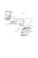
LED検査装置1は、図1に示すように、画像判定コントローラ10と、カメラユニット11と、表示装置12と、光ファイバ13と、検査制御ユニット14とを備えている。<Device configuration>
The LED inspection device inspects whether the display color (luminance component (Y), color component (UV)) and lighting / extinguishing state of each lighting pattern of LEDs that are a plurality of light emitters are appropriate, respectively. It is an apparatus which determines the quality of LED.
As shown in FIG. 1, the LED inspection apparatus 1 includes an
画像判定コントローラ10は、カメラユニット11から出力される画像信号を基に複数のLED15の各点灯パターンにおける表示色及び点灯・消灯状態を判別する。
画像判定コントローラ10では、輝度成分及び色成分に係る所定の検査マスターデータを予め生成することができ、この検査マスターデータを格納することができる。The
The
また、画像判定コントローラ10では、各点灯パターンにおいて、LED15の消灯状態における消灯色を黒色として設定して、検査マスターデータを予め生成することにより、LED15の点灯・消灯状態の判別を可能にする。
LED15の点灯・消灯状態を判別することにより、LED15が配置された電子回路において短絡、断線が生じたこと等を検知することができる。すなわち、複数のLED15が実装されたプリント基板16上等で短絡が生じた場合には、本来消灯状態にあるべきLED15が点灯してしまい、断線が生じた場合には、本来点灯するべきLED15が点灯せずに非導通であることから、短絡、断線を検知することができる。In addition, the
By determining the lighting / extinguishing state of the
画像判定コントローラ10は、格納した検査マスターデータとカメラユニット11から出力される画像信号を比較することでLED15の表示色及び点灯・消灯を判別する。また、画像判定コントローラ10は、LED15の表示色(輝度成分及び色成分)の測定結果を液晶表示装置等でなる表示装置12に対して数値或いは具体的な色表現で出力可能となっている。なお、画像判定コントローラ10によるLED15の輝度成分及び色成分に係る判別の詳細については後述する。 The
カメラユニット11は、導光手段である光ファイバ13を介して導光したLED15の光を撮像するCCD(Charge Coupled Device)111(図2、図3、図4)を有する。なお、本実施の形態では、撮像手段としてCCD111を用いているがCMOS等の撮像素子を用いても構わない。カメラユニット11は、画像判定コントローラ10と通信可能に接続されており、CCD111で撮像した画像信号をビデオ信号として画像判定コントローラ10に出力する。また、カメラユニット11は、画像判定コントローラ10からカメラ制御信号を受信して、シャッタースピード、ゲイン調整等のカメラ設定を変更することができ、CCD111から取り込むLED15の光量の調整等が可能となっている。なお、具体的には本実施の形態では、画像判定コントローラ10とカメラユニット11は、カメラ制御信号及びビデオ信号を通信ケーブルを介してやり取りする。 The
カメラユニット11では、CCD111と複数の光ファイバ13の照射側の端部とを対向するように配置して、CCD111で光ファイバ13から導光したLED15の光を撮像する。光ファイバ13の照射側の端部のCCD111側には拡散フィルタ118(図3)が配置されており、CCD111で撮像するLED15からの光の受光範囲を十分に確保している。
また、カメラユニット11には、検査対象である複数のLED15の光の輝度、点灯・消灯パターン及び配置に応じて、減光フィルタ116AをCCD111と光ファイバ13との間に配設可能であり、配設した場合には検査精度の向上を図ることができる。これについての詳細は後述する。In the
Further, the
カメラユニット11においてCCD111の前面には、ベイヤ配列されたカラーフィルタが配設されており、撮像したLED15からの光をRGBに対応する画像信号として取得する。ここで、本実施の形態においてカメラユニット11は、CCD111で取得したRGBに対応する画像信号をNTSC(National Television System Committee)方式のビデオ信号に変換して画像判定コントローラ10に出力する。NTSC方式のビデオ信号は、輝度信号(Y信号)及び色信号(C信号:輝度信号と青色成分の差分信号(U信号)と、輝度信号と赤色成分の差分信号(V信号)とを加算したもの)からなる信号であり、本実施の形態に係るLED検査装置は輝度成分及び色成分を判別するものであるため、カメラユニット11においてビデオ信号に変換して出力することで処理の効率化を図っている。 In the
光ファイバ13は、LED15の光をカメラユニット11まで導光する。光ファイバ13は検査対象である複数のLED15の数に応じて複数用意される。光ファイバ13は、照射側の一端がカメラユニット11と結合してCCD111に向けて光を照射するように配置され、他端がLED15と対向されてLED15からの光を導光するように配置される。光ファイバ13は、その指向特性により予め定められた角度の範囲において光を受光するものであるため、隣接する他のLED15からの光や外光の影響を受けにくく検査対象の光を安定して受光できる。また、光ファイバ13は、上下方向からの受光のみならず、横方向や斜め方向からの受光も可能であるため、検査対象であるLED15の配置構成によらず柔軟に検査を行うことを可能とする。また、光ファイバ13を用いることにより、検査対象であるLED15が実装されたプリント基板16が大型である場合もカメラユニット11の画角の調整等をする必要もないため、装置構成を小型化できる。 The
検査制御ユニット14は、検査対象である複数の発光体であるLED15を搭載する。LED15は典型的にはプリント基板16に複数実装されたかたちで検査制御ユニット14に搭載される。この場合、検査制御ユニット14はプリント基板16と電気的に接続することができ、プリント基板16に実装された各LED15の発光の制御、具体的には各点灯パターンでの点灯・消灯、点灯方式の変更(スタティック点灯、ダイナミック点灯、発光色の変更等)等の制御を行うことができる。本実施の形態では、画像判定コントローラ10と検査制御ユニット14が通信可能に接続されており、検査制御ユニット14からの制御信号を基に、画像判定コントローラ10の制御を行うように構成されている。 The
LED15は、検査対象として上述のように検査制御ユニット14に搭載される。本実施の形態において、LED15はプリント基板16に複数実装されるかたちで検査制御ユニット14に搭載され、それぞれのLED15に光ファイバ13が配される。また、本実施の形態に係るLED検査装置では、LED15の種別として低輝度から高輝度のもの、単色及びフルカラーのものが複数あることを想定しており、カメラユニット11の一度の撮像で複数のLED15の光をまとめて撮像することで瞬時に検査を行うことを想定している。なお、ここではLED15がプリント基板16に複数実装された実装状態で検査を行う例を挙げているが、本実施の形態に係るLED検査装置では、この他の態様の検査も可能である。例えば、製品の完成状態で複数のLED15をまとめて検査することもできる。具体的な製品としては、例えば7セグメントディスプレイ、パチンコ台、車両のブレーキ、蛍光灯等が挙げられる。 The
次に、カメラユニット11及び画像判定コントローラ10のシステム構成について図2を用いて説明する。
カメラユニット11は、CCD111、AGCアンプ(オートゲインコントロール・アンプ)112、YC変換回路113、タイミングジェネレータ(TG)114、通信インタフェース(通信I/F)115を有する。また、カメラユニット11には、必要に応じて減光フィルタ116Aが設けられる。Next, the system configuration of the
The
CCD111は、LED15の光を導光した光ファイバ13からの光を、必要に応じて、減光フィルタ116Aを介して受光し、ビデオ信号を出力する。AGCアンプ112は、ゲインを変更する増幅器であり、設定されたゲインに応じてCCD111からの画像信号を増幅する。AGCアンプ112は、画像判定コントローラ10からのカメラ制御信号に応じてゲインの調整が可能となっている。 The
YC変換回路113は、CCD111及びAGCアンプ112を介して出力された画像信号をY信号及びC信号に変換しビデオ信号として、通信インタフェース115から通信ケーブルを介して画像判定コントローラ10に出力する。タイミングジェネレータ114は、CCD111のシャッタースピードを調整するための制御信号をCCD111に対して出力する。この場合、タイミングジェネレータ114は、画像判定コントローラ10から出力されたカメラ制御信号を基に制御を行う。通信インタフェース115は、画像判定コントローラ10と通信を行うためのインタフェースであり、通信ケーブルを介して画像判定コントローラ10からのカメラ制御信号を入力し、またYC変換回路113からのビデオ信号を画像判定コントローラ10に出力する。 The
減光フィルタ116Aは、ND(Neutral Density)フィルタとも呼ばれ、中性濃度フィルタの意味で、様々な濃さのグレーで構成されたフィルタであり、色に影響なく光学系レンズ117(図3、図4)に入る光量を減少させて調節する役目を持つ。具体的には、光量を1/2にするND2、1/4にするND4、1/8にするND8等がある。 The neutral density filter 116 </ b> A is also called an ND (Neutral Density) filter, and is a filter composed of gray of various densities in the meaning of a neutral density filter. The optical system lens 117 (FIG. 3, FIG. 3) 4) to reduce and adjust the amount of light entering. Specifically, there are ND2 for setting the light quantity to 1/2, ND4 for setting to 1/4, ND8 for setting to 1/8, and the like.
次に、画像判定コントローラ10は、A/D変換回路101、通信インタフェース(通信I/F)102、入力装置104、CPU(Central Processing Unit)105、ROM(Read Only Memory)106、RAM(Random Access Memory)107を有する。 Next, the
A/D変換回路101は、カメラユニット11のYC変換回路113から出力されたビデオ信号をY/C分離し、分離したY信号及びC信号をデジタル信号に変換する。詳しくは、8ビットAD変換により、Y信号につき256階調のデジタル信号、U信号につき256階調のデジタル信号、V信号につき256階調のデジタル信号(C信号につき65536階調のデジタル信号)に変換する。通信インタフェース102は、外部機器とのデータや信号のやり取りを行うインタフェースであり、CPU105の制御により、カメラユニット11に対するカメラ制御信号、表示装置12に対する画像信号等を出力する。また、通信インタフェース102は、カメラユニット11からのビデオ信号を入力し、CPU105の制御によりA/D変換回路101に出力する。 The A /
入力装置104は、例えばスイッチ等で構成される操作部であって、操作部からの指示をCPU105に出力する。CPU105は、画像判定コントローラ10を統括的に制御する中央処理装置であり、ROM106は、CPU105が各種処理に用いるプログラムを格納する。CPU105がROM106に格納されたプログラムを実行する際は、RAM107を作業領域として用いる。本実施の形態においてCPU105は、主に画像判定に係る処理を実行する。この場合CPU105は、ROM106に格納された専用プログラムを実行し、必要なデータについて、A/D変換回路101で変換された画像信号(デジタル信号)の格納や輝度及び色、点灯・消灯状態の判定等の制御を行う。 The
<カメラユニットの構成>
ここでカメラユニット11のより具体的な構造について図3を用いて説明する。カメラユニット11において、CCD111の被写体側には、接写リングを介して光学系レンズ117が配される。光学系レンズ117の前面(被写体側)には、拡散フィルタ118及びファイバブロック119が設けられ、ファイバブロック119には複数の光ファイバ13の照射側の端部がそれぞれ複数のポートに挿通するかたちで集約されている。
ファイバブロック119の複数のポートは規則的に配列されており、各ポートには例えば1〜100までの領域座標が予め割り付けられている。画像判定コントローラ10により、検査対象となるLED15の輝度成分、色成分、種類、数等に応じて、領域座標が割り付けられたポートのうちどのポートを用いるか等を選択することができる。
このような構成により、CCD111はファイバブロック119を被写体として撮像を行うことで、拡散フィルタ118を介して拡散された検査対象である複数のLED15の光を撮像することが可能となっている。
なお、ファイバブロック119は、検査対象となるLED15の態様に応じて交換が可能である。<Configuration of camera unit>
Here, a more specific structure of the
A plurality of ports of the
With such a configuration, the
The
カメラユニット11は、複数のLED15の光をまとめて撮像して画像信号を取得するものである。このような場合、撮像する複数のLED15の光の輝度、点灯・消灯パターン及び配置によっては、正確な画像信号を取得できない場合がある。そのため、カメラユニット11は、必要に応じて、減光フィルタ116AをCCD111と光ファイバ13との間に設置して複数のLED15の光を撮像する。 The
減光フィルタ116Aは、支持板116A1、116A2を介して、光の入射方向及び入射方向と直交する方向(図3において紙面上下方向及び紙面左右、直交方向)に移動可能に設けられる。
支持板116A1は、減光フィルタ116Aを着脱可能に支持し、案内構造を備えた支持板116A2において光の入射方向と直交する方向に移動可能に支持される。また、支持板116A2は、カメラユニット11の側壁において光の入射方向に移動可能に支持される。これにより、減光フィルタ116Aを、必要に応じてファイバブロック119における任意のポート上に配置できるようになっている。The
The support plate 116A1 removably supports the
次に、減光フィルタ116Aを配置する場合について図4を用いて説明する。図4は、検査対象であるLED15A,15Bが検査制御ユニット14に搭載されている状態を示しており、これらのLED15A,15Bの光の輝度差が大きいものとする(例えばLED15Aの輝度が10000mcd、LED15Bの輝度が300mcd)。 Next, the case where the
LED15は高輝度になるにつれて、白色に近づくためにその正確な色を取り込むためには、光量を絞って輝度を抑えて撮像する必要があるが、高輝度のLED15Aのために光量を絞ってしまうと、低輝度のLED15Bは元々の発光量が低いために、CCD111に十分な光が取り込めなくなってしまう。
本実施の形態のLED検査装置1では、各点灯パターンにおいて、消灯するLED15を黒色(消灯色)として設定して、LED15の表示色のみならず点灯・消灯状態の判別もするので、低輝度のLED15Bからの光を十分にCCD111に取り込めないと、低輝度のLED15Bの点灯と消灯の判別が困難になってしまう。As the
In the LED inspection apparatus 1 according to the present embodiment, in each lighting pattern, the
このようにLED15の表示色及び点灯・消灯状態をともに判別する本実施の形態に特有の問題を解決するために、本実施の形態に係るカメラユニット11では、CCD111と光ファイバ13の照射側の端部との間に減光フィルタ116Aを配置し、所定の輝度よりも輝度の高い高輝度のLED15Aからの光量を減少させて調節して撮像を行うようにする。
より詳しくは、減光フィルタ116Aは、ファイバブロック119の所定の輝度よりも高いLED15Aに対応するポートに配置される。光ファイバ13を用いてLED15の光を導光する態様では、所定のLED15に対応する光ファイバ13を明確に区別できるため、減光フィルタ116Aを必要に応じて正確かつ容易に配置することができる。
なお、本実施の形態では減光フィルタ116Aをファイバブロック119のポートに支持板116A1を移動させて設けるが、これに代えて、減光フィルタ116Aを所定のポートに直接付設するようにしても構わない。
また、減光フィルタ116Aが所定のポートに対応して配置されたファイバブロック119を予め用意しておいて、複数のLED15それぞれに対応する光ファイバ13の照射側の端部をファイバブロック119のポートに選択的に挿通させるようにしてもよい。Thus, in order to solve the problem peculiar to the present embodiment in which both the display color of the
More specifically, the neutral density filter 116 </ b> A is disposed at a port corresponding to the
In this embodiment, the
In addition, a
そして、カメラユニット11で、LED15A,15Bの各点灯パターンにおいて、減光フィルタ116Aを介して基準となるマスター基板の高輝度のLED15Aからの光量を減少させて調節して撮像するとともに、低輝度のLED15Bについては直接撮像し、これを基に検査マスターデータを画像判定コントローラ10で生成し格納しておく。なお、マスター基板はLED15の検査をする上で基準となるLED15を実装したものであり、基準とする輝度成分及び色成分の検査マスターデータを取得するためのものである。 Then, in each lighting pattern of the
検査マスターデータを生成した後は、カメラユニット11で、マスター基板における場合と同様に、検査対象となるプリント基板16上のLED15A,15Bを各点灯パターンにおいて撮像して、画像信号を画像判定コントローラ10に出力し、先に生成した検査マスターデータと比較する。これにより、本実施の形態に係るLED検査装置1では、LED15A,15Bの光の輝度成分及び色成分、点灯・消灯の状態が適正であるかどうかを判断する。なお、検査マスターデータは、所定のLED15の光に対する適正な輝度成分及び色成分の範囲を定めたものであり、光がこの所定の閾値内にある場合に適正であると判断するためのものである。
また、減光フィルタ116Aの種類の選択に関しては、減光フィルタ116Aを設けるLED15の光の予め定められた輝度成分の情報を基に、光量の減少の度合いを考慮して適宜選択するようにする。例えば、LED15間の輝度差が2倍の場合にはND2、輝度差が4倍の場合にはND4、輝度差が8倍の場合にはND8の減光フィルタ116Aを用いるようにするとよい。After generating the inspection master data, the
In addition, regarding the selection of the type of the
<LED検査装置における検査手順>
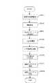
次に、本実施の形態に係るLED検査装置における検査手順を図5及び図6を用いて説明する。先ず図5を用いて検査マスターデータの生成、格納までの手順を説明する。<Inspection procedure in LED inspection device>
Next, an inspection procedure in the LED inspection apparatus according to the present embodiment will be described with reference to FIGS. First, the procedure up to the generation and storage of inspection master data will be described with reference to FIG.
先ずステップS501においては、画像判定領域を設定する。すなわち、検査対象となる複数のLED15に対応する光ファイバ13を全て撮像できるように、画像判定コントローラ10により、ファイバブロック119において領域座標が割り付けられたポートの中から所望のポートを選択して撮像範囲を設定する。 First, in step S501, an image determination area is set. In other words, the
次に、ステップS502において、画像判定コントローラ10は、CPU105の制御により、LED15の光の輝度成分の閾値及び色成分の閾値を設定する。ここで本実施の形態では、輝度成分を256階調で表現し、色成分を65536階調で表現するため、この階調のそれぞれの範囲において光の輝度成分及び色成分の閾値を設定しておく。
また、LED15の各点灯パターンにおける消灯状態を表わす消灯色を黒色として設定し、この消灯色に該当する輝度成分及び色成分の閾値も設定しておく。
具体的には、LED15の消灯状態を表わす消灯色の黒色は、Y信号(輝度成分)が256階調中0〜30階調であり、かつ、UV信号(色成分)がともに256階調中128±15階調である(UV座標の中心を黒とする。)と定義して設定する。
よって、LED15の点灯状態は、Y信号(輝度成分)が256階調中31階調以上に該当する場合として定義される。
これにより、本来消灯すべきLED15の異常な点灯状態や本来点灯すべきLED15の異常な消灯状態を検出することができ、LED15が所望どおりの点灯状態または消灯状態であるかを検査することができる。
なお、消灯色としての黒色の設定は、A/D変換回路101の分解能や検査対象などによって適宜決定される。In step S <b> 502, the
Moreover, the light-off color indicating the light-off state in each lighting pattern of the
Specifically, the black color of the unlit color representing the unlit state of the
Therefore, the lighting state of the
Thereby, it is possible to detect an abnormal lighting state of the
Note that the setting of black as the extinguishing color is appropriately determined depending on the resolution of the A /
次に、ステップS503において、検査制御ユニット14により、検査の基準となるマスター基板における複数のLED15を各点灯パターンで点灯させ、点灯パターンごとに検査制御ユニット14から画像判定コントローラ10に対して制御信号(I/O信号等)を出力する。 Next, in step S503, the
次に、ステップS504において、画像判定コントローラ10は、CPU105の制御により、LED15の点灯パターンごとに、通信インタフェース102からカメラユニット11に対してカメラ制御信号を出力して、各点灯パターンにおけるLED15からの光を、受光、導光した光ファイバ13、ファイバブロック119、及び、必要に応じて減光フィルタ116Aを介してCCD111でそれぞれ撮像し、LED15の全点灯パターンについて撮像する。 Next, in step S504, the
次に、ステップS505では、カメラユニット11において、CCD111及びAGCアンプ112を介して出力された各点灯パターンにおけるLED15の光のビデオ信号がYC変換回路113によりY信号及びC信号からなるビデオ信号に変換される。次に、画像判定コントローラ10は、カメラユニット11から、Y信号及びC信号からなるビデオ信号に変換されたアナログ信号を受信する。 Next, in step S505, in the
次に、ステップS506において、画像判定コントローラ10は、カメラユニット11から出力されたビデオ信号をA/D変換回路101を介してデジタル信号に変換する。より詳しくは、ビデオ信号に含まれるY信号から256階調で表現される輝度成分を示すデジタル信号を生成し、C信号から65536階調で表現される色成分を示すデジタル信号を生成する。ここでは輝度成分をY信号から表現でき、色成分をC信号から生成するため、効率的な変換が可能になっている。 Next, in step S506, the
次に、ステップS507において、画像判定コントローラ10は、ステップS506で変換したデジタル信号を基に、CPU105の制御により基準値となる検査マスターデータを生成する。なお、LED15の全点灯パターンについて検査マスターデータは生成される。
検査マスターデータは、ステップS502で設定した、階調の各範囲におけるLED15の光に対する輝度成分及び色成分の閾値を基に、撮像したLED15の光に対応する輝度成分及び色成分の基準を定めたものである。ここで、減光フィルタ116Aを介して撮像されたLED15の画像信号は、特性を変化されて階調化されることになり、これに応じた閾値が検査マスターデータにおいて設定される。Next, in step S507, the
The inspection master data sets the reference of the luminance component and the color component corresponding to the light of the imaged
次に、ステップS508において、画像判定コントローラ10は、CPU105の制御により、ステップS507で生成した検査マスターデータをROM106に格納しておく。 In step S508, the
以上が、本実施の形態に係るLED検査装置における検査マスターデータの生成手順である。なお、ステップS506ではアナログ信号(Y信号、C信号)をデジタル階調化し、ステップS507ではデジタル階調化されたデータを検査マスターデータとして生成するようにしている。これは表示装置12等で色を表示する際にカラーパレット表現をし易くするためである。 The above is the procedure for generating inspection master data in the LED inspection apparatus according to the present embodiment. In step S506, the analog signals (Y signal and C signal) are converted into digital gradations, and in step S507, the digital gradation data is generated as inspection master data. This is to facilitate color palette expression when displaying colors on the
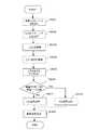
次に、生成した検査マスターデータと検査データとを比較してLED15の表示色及び点灯・消灯を検査する手順を図6を用いて説明する。 Next, a procedure for comparing the generated inspection master data with the inspection data and inspecting the display color and lighting / extinction of the
先ずステップS601において、画像判定コントローラ10は、CPU105の制御により検査マスターデータをROM106から読み出す。 First, in step S <b> 601, the
次に、ステップS602において、検査制御ユニット14により、検査対象となるプリント基板16上の複数のLED15を各点灯パターンにて点灯させ、点灯パターンごとに検査制御ユニット14から画像判定コントローラ10に対して制御信号(I/O信号等)を出力する。 Next, in step S602, the
次にステップS603において、画像判定コントローラ10は、CPU105の制御により、LED15の点灯パターンごとに、通信インタフェース102からカメラユニット11に対してカメラ制御信号を出力して、各点灯パターンにおけるLED15の光を、受光,導光した光ファイバ13、ファイバブロック119、及び、必要に応じて減光フィルタ116Aを介してCCD111でそれぞれ撮像し、LED15の全点灯パターンについて撮像する。 In step S <b> 603, the
次に、ステップS604において、カメラユニット11において、CCD111及びAGCアンプ112を介して出力されたLED15の光のビデオ信号がYC変換回路113によりY信号及びC信号からなるビデオ信号に変換される。次に、画像判定コントローラ10は、カメラユニット11から、Y信号及びC信号からなるビデオ信号に変換されたアナログ信号を受信する。 Next, in step S604, in the
次に、ステップS605において、画像判定コントローラ10は、カメラユニット11から出力されたビデオ信号をA/D変換回路101を介してデジタル信号に変換する。より詳しくは、ビデオ信号に含まれるY信号から256階調で表現される輝度成分を示すデジタル信号を生成し、C信号から65536階調で表現される色成分を示すデジタル信号を生成する。 In step S <b> 605, the
次に、ステップ606において、画像判定コントローラ10は、CPU10の制御により検査マスターデータとステップS605で生成した検査データとを比較し、撮像した各点灯パターンにおけるLED15の光に対応する検査データが所定の閾値の範囲であるか否かを判別し、それぞれのLED15の光について所定の閾値の範囲内である場合はステップS607に進み(OK)、そうでない場合はステップS608に進む(NG)。
すなわち、ステップ606においては、検査マスターデータと検査データを比較することにより、それぞれのLED15が各点灯パターンにおいて、所望の表示色及び所望の点灯・消灯状態で表示されるか否かを判別する。Next, in
That is, in
ステップS607においては、画像判定コントローラ10は、CPU105の制御により通信インタフェース102から表示装置12に対して、各点灯パターンにおけるそれぞれのLED15の表示色及び点灯・消灯状態が適正である旨を示す信号を出力し、表示装置12は、それぞれのLED15について「OK表示」をしたり、表示装置12に備えられたスピーカから適正である旨を示すブザー出力をする。 In step S <b> 607, the
一方、ステップS608においては、画像判定コントローラ10は、CPU105の制御により通信インタフェース102から表示装置12に対して、各点灯パターンにおけるそれぞれのLED15の表示色及び点灯・消灯状態が適正でない旨を示す信号を出力し、表示装置12はそれぞれのLED15について「NG表示」をしたり、スピーカから適正でない旨を示すブザー出力をする。 On the other hand, in step S608, the
そして、ステップS609においては、画像判定コントローラ10は、CPU105により表示装置12に対して各LED15について測定データの表示、閾値、測定値等の検査結果表示を行う。 In step S <b> 609, the
このように本実施の形態では、プリント基板16等に実装された複数のLED15の各点灯パターンにおける消灯状態を表わす消灯色を黒色として設定するようにしたので、各点灯パターンにおける各LED15の表示色の検査のみならず、各LED15の点灯状態・消灯状態の検査も一度の撮像により行えるようにしたので、複数のLED15の表示色及び点灯・消灯状態が適正であるか否かの検査を高精度で高速で効率的に行うことができる。 As described above, in this embodiment, the light-off color representing the light-off state in each light-on pattern of the plurality of
また、本実施の形態では、回路短絡によりLED15が暗く僅かに点灯する場合であっても、検査マスターデータと検査データを比較することにより、高精度で異常点灯を検出することができる。 In the present embodiment, even when the
また、本実施の形態では、プリント基板16上の複数のLED15が輝度差の大きいLED15A,15Bを含む場合には、高輝度のLED15Aに関し減光フィルタ116Aを介して検査マスターデータを生成しておくとともに、検査の際にも高輝度のLED15Aに関し減光フィルタ116Aを介して検査データを取得し、両者を比較することで検査を行い、高輝度のLED15Aを含めたLED15の良否の判定を一度に行う。
このようにすることで、高輝度のLED15Aの撮像のために光量を絞る必要がなくなり、低輝度のLED15Bの点灯と消灯の判別についても高精度で行うことができる。In the present embodiment, when the plurality of
By doing so, it is not necessary to reduce the amount of light for imaging the high-
また、本実施の形態のLED検査装置は、検査対象となるLED15がどのような態様であっても、支持板116A1,116A2を介して減光フィルタ116Aの位置を移動させたり、ファイバブロック119の各ポートに光ファイバ13の照射側の端部を選択的に挿通したり、または、ファイバブロック119自体を交換するだけで、検査が可能であるので、汎用性に優れている。 Further, the LED inspection apparatus according to the present embodiment can move the position of the
以上、実施の形態を挙げて本発明を説明したが、本発明は上記実施の形態に限定されるものではなく、種々変形が可能である。例えば、本実施の形態では、本発明に係るLED検査装置を、画像判定コントローラ10、カメラユニット11に接続し、画像判定コントローラ10でカメラユニット11を制御するようにしたが、画像判定コントローラ10をパーソナルコンピュータに接続して、パーソナルコンピュータから画像判定コントローラ10を介してカメラユニット11を制御するようにしたり、画像判定コントローラ10からの検査結果の出力をパーソナルコンピュータにおける表示装置に表示する態様としても構わない。 While the present invention has been described with reference to the embodiment, the present invention is not limited to the above embodiment, and various modifications can be made. For example, in the present embodiment, the LED inspection apparatus according to the present invention is connected to the
また、本発明では、二種類以上の減光フィルタ116Aを1個のファイバブロック119の所定のポートに対応して配置することも可能であり、これにより様々な輝度のLED15の検査が可能になる。 In the present invention, it is also possible to arrange two or more types of
また、本発明では、LED15の表示色、点灯・消灯状態を検査することにより、LED15の制限抵抗の値の異常を検出することも可能である。 In the present invention, it is also possible to detect an abnormality in the value of the limiting resistance of the
また、本実施の形態では、図4において、理解しやすくするため便宜上、光の輝度差の大きいLED15A,15Bのみがプリント基板16に実装されたものを表わしたが、その他のLEDがプリント基板16に実装された場合に検査することももちろん可能である。 Further, in the present embodiment, in FIG. 4, for convenience of illustration, only the
1 LED検査装置
10 画像判定コントローラ
11 カメラユニット
12 表示装置
13 光ファイバ
14 検査制御ユニット
15 LED
16 プリント基板
101 A/D変換回路
102 通信インタフェース
104 入力装置
105 CPU
106 ROM
107 RAM
111 CCD
112 AGCアンプ
113 YC変換回路
114 タイミングジェネレータ
115 通信インタフェース
116A 減光フィルタ
116A1、116A2 支持板
117 光学系レンズ
118 拡散フィルタ
119 ファイバブロックDESCRIPTION OF SYMBOLS 1
16 Printed circuit board 101 A /
106 ROM
107 RAM
111 CCD
112
Claims (9)
Translated fromJapanese各点灯パターンにおける前記複数のLEDからの光をそれぞれ導光する導光工程と、
前記導光工程でそれぞれ導光した前記複数のLEDからの光を撮像する工程と、
前記撮像工程で撮像した画像信号を輝度信号及び色信号からなるビデオ信号に変換し、該輝度信号及び色信号をデジタル信号に変換することによりそれぞれ階調化した輝度成分及び色成分に係る階調値を、前記LEDの表示色の輝度成分及び色成分それぞれについて予め所定の階調値として定めた基準値、及び、前記LEDの消灯状態における消灯色として設定した黒色の輝度成分及び色成分それぞれについて予め所定の階調値の範囲として定めた基準値と比較する検査工程とを有することを特徴とするLED検査方法。An LED inspection method for inspecting display colors and lighting / extinguishing states of a plurality of LEDs,
A light guide step for guiding light from the plurality of LEDs in each lighting pattern;
Imaging light from the plurality of LEDs respectively guided in the light guiding step;
Thegradations relatingto the luminance component and the color componentobtained by converting the image signal captured in the imaging step into a video signal composed of a luminance signal and a color signal, and converting the luminance signal and the color signalinto a digital signal, respectively. the value, the reference value determined in advanceas a predetermined gradation value foreach of the luminance and chrominance of the display color of the LED, and, foreach of the luminance and chrominance black set as off color in oFF state of the LED An LED inspection method comprising: an inspection step of comparing with a reference value determined in advance as apredetermined gradation value range .
各点灯パターンにおける前記複数のLEDからの光をそれぞれ導光する導光手段と、
前記導光手段でそれぞれ導光した前記複数のLEDからの光を撮像する撮像手段と、
前記撮像手段で撮像した画像信号を輝度信号及び色信号からなるビデオ信号に変換し、該輝度信号及び色信号をデジタル信号に変換することによりそれぞれ階調化した輝度成分及び色成分に係る階調値を、前記LEDの表示色の輝度成分及び色成分それぞれについて予め所定の階調値として定めた基準値、及び、前記LEDの消灯状態における消灯色として設定した黒色の輝度成分及び色成分それぞれについて予め所定の階調値の範囲として定めた基準値と比較する検査手段とを備えたことを特徴とするLED検査装置。An LED inspection device for inspecting the display color and lighting / extinguishing state of a plurality of LEDs,
A light guiding means for guiding light from the plurality of LEDs in each lighting pattern;
Imaging means for imaging light from the plurality of LEDs respectively guided by the light guiding means;
Thegradations relatingto the luminance component and the color componentobtained by converting the image signal captured by the imaging means into a video signal composed of a luminance signal and a color signal, and converting the luminance signal and the color signalinto a digital signal, respectively. the value, the reference value determined in advanceas a predetermined gradation value foreach of the luminance and chrominance of the display color of the LED, and, foreach of the luminance and chrominance black set as off color in oFF state of the LED An LED inspection apparatus comprising: an inspection unit that compares with a reference value determined in advance as apredetermined gradation value range .
複数のポートを有し、該複数のポートのうち所定のポートに対応して前記減光フィルタが配置され、前記複数のポートには前記光ファイバを選択的に挿通可能であり、
検査対象に応じて交換が可能であるファイバブロックを備えたことを特徴とする請求項7に記載のLED検査装置。The imaging means includes
A plurality of ports, wherein the neutral density filter is disposed corresponding to a predetermined port of the plurality of ports, the optical fiber can be selectively inserted into the plurality of ports,
The LED inspection apparatus according to claim 7, further comprising a fiber block that can be replaced in accordance with an inspection target.
Priority Applications (1)
| Application Number | Priority Date | Filing Date | Title |
|---|---|---|---|
| JP2009230956AJP4530429B1 (en) | 2009-04-14 | 2009-10-02 | LED inspection method and LED inspection apparatus |
Applications Claiming Priority (2)
| Application Number | Priority Date | Filing Date | Title |
|---|---|---|---|
| JP2009098502 | 2009-04-14 | ||
| JP2009230956AJP4530429B1 (en) | 2009-04-14 | 2009-10-02 | LED inspection method and LED inspection apparatus |
Publications (2)
| Publication Number | Publication Date |
|---|---|
| JP4530429B1true JP4530429B1 (en) | 2010-08-25 |
| JP2010266424A JP2010266424A (en) | 2010-11-25 |
Family
ID=42767920
Family Applications (1)
| Application Number | Title | Priority Date | Filing Date |
|---|---|---|---|
| JP2009230956AActiveJP4530429B1 (en) | 2009-04-14 | 2009-10-02 | LED inspection method and LED inspection apparatus |
Country Status (1)
| Country | Link |
|---|---|
| JP (1) | JP4530429B1 (en) |
Cited By (2)
| Publication number | Priority date | Publication date | Assignee | Title |
|---|---|---|---|---|
| CN112004284A (en)* | 2020-09-14 | 2020-11-27 | 晓能互联科技(深圳)有限公司 | Address positioning system and method for LED lamp string |
| CN117351857A (en)* | 2023-10-23 | 2024-01-05 | 广州隧华智慧交通科技有限公司 | LED screen general control detecting system |
Families Citing this family (5)
| Publication number | Priority date | Publication date | Assignee | Title |
|---|---|---|---|---|
| KR101182822B1 (en)* | 2011-03-29 | 2012-09-13 | 삼성전자주식회사 | Inspection apparatus and method of light emitting device |
| JP5891995B2 (en)* | 2012-08-06 | 2016-03-23 | 富士通株式会社 | Inspection method and inspection system |
| JP2014212438A (en)* | 2013-04-18 | 2014-11-13 | ヴイ・インターネットオペレーションズ株式会社 | Monitoring system |
| KR102800186B1 (en)* | 2019-12-17 | 2025-04-28 | 에스케이하이닉스 주식회사 | Apparatus for sensing temperature and temperature sensing system having the same |
| JP7127863B2 (en) | 2020-01-27 | 2022-08-30 | 株式会社フュージョンテク | Darkroom box for light source monitoring and light source monitoring system |
Family Cites Families (10)
| Publication number | Priority date | Publication date | Assignee | Title |
|---|---|---|---|---|
| JPH06174587A (en)* | 1992-12-07 | 1994-06-24 | Toray Eng Co Ltd | Inspection method for liquid crystal display panel |
| JPH085548A (en)* | 1994-06-22 | 1996-01-12 | Technol Res Assoc Of Medical & Welfare Apparatus | Light scanning apparatus |
| JP3282644B2 (en)* | 1994-07-11 | 2002-05-20 | 日本電信電話株式会社 | Optical component inspection equipment |
| JPH08166341A (en)* | 1994-12-14 | 1996-06-25 | Technol Res Assoc Of Medical & Welfare Apparatus | Optical ct |
| JPH09113444A (en)* | 1995-10-20 | 1997-05-02 | Technol Res Assoc Of Medical & Welfare Apparatus | Optical fiber photometer |
| JPH1082732A (en)* | 1996-09-09 | 1998-03-31 | Shimadzu Corp | Optical measuring device |
| JPH11201868A (en)* | 1998-01-13 | 1999-07-30 | Fujitsu Denso Ltd | Inspecting apparatus for multicolor light emitting display apparatus |
| JP2003057146A (en)* | 2001-08-09 | 2003-02-26 | Toshiba Corp | Method and apparatus for evaluating color display device |
| JP2004311209A (en)* | 2003-04-07 | 2004-11-04 | Oputeru:Kk | Inspection method and device for light emitting element |
| JP2008216334A (en)* | 2007-02-28 | 2008-09-18 | Nippon Signal Co Ltd:The | Detecting method and detecting device for screen display fault |
- 2009
- 2009-10-02JPJP2009230956Apatent/JP4530429B1/enactiveActive
Cited By (3)
| Publication number | Priority date | Publication date | Assignee | Title |
|---|---|---|---|---|
| CN112004284A (en)* | 2020-09-14 | 2020-11-27 | 晓能互联科技(深圳)有限公司 | Address positioning system and method for LED lamp string |
| CN117351857A (en)* | 2023-10-23 | 2024-01-05 | 广州隧华智慧交通科技有限公司 | LED screen general control detecting system |
| CN117351857B (en)* | 2023-10-23 | 2024-05-28 | 广州隧华智慧交通科技有限公司 | LED screen general control detecting system |
Also Published As
| Publication number | Publication date |
|---|---|
| JP2010266424A (en) | 2010-11-25 |
Similar Documents
| Publication | Publication Date | Title |
|---|---|---|
| JP4530429B1 (en) | LED inspection method and LED inspection apparatus | |
| CN108445007B (en) | Detection method and detection device based on image fusion | |
| CN104819984B (en) | The check device and inspection method of printed circuit board (PCB) outward appearance | |
| CN1212004C (en) | Image processing device and method | |
| KR100910593B1 (en) | Bad pixel detection method and bad pixel detection device of LED display board | |
| WO2013175703A1 (en) | Display device inspection method and display device inspection device | |
| KR20140070120A (en) | display device color- calibration apparatus and method thereof | |
| CN1982857B (en) | Method for automatically measuring luminescent device | |
| JP2020201086A (en) | Inspection device of led-mounted substrate | |
| KR101640555B1 (en) | Camera Test Apparatus | |
| JP2010139324A (en) | Color irregularity measuring method and color irregularity measuring device | |
| KR100807249B1 (en) | Camera test unit and camera inspection method using the same | |
| US11526978B2 (en) | Image processing method for light emitting device | |
| KR20200081541A (en) | Imaging apparatus and driving method of the same | |
| JP2010098364A (en) | Method and device for measuring moving picture response characteristic using line sensor | |
| US9019382B2 (en) | Diagnosis unit for an electronic camera and camera system | |
| TWI744007B (en) | Luminous material image processing method | |
| JP2009053019A (en) | Chart, system and method for testing resolution | |
| CN110599551B (en) | Image processing apparatus, image processing method, and storage medium | |
| JP2010139323A (en) | Color irregularity measuring method and color irregularity measuring device | |
| TWI470207B (en) | A method of building up gray-scale transform function, a panel testing method and an automated panel testing system | |
| CN111263140B (en) | Apparatus, system and method | |
| TWI734928B (en) | Method for detecting luminescence distribution of laser chip and method for displaying luminous intensity of laser chip | |
| US20240331185A1 (en) | Method of obtaining brightness information of display panel and related panel detection system | |
| JP2010145097A (en) | Color unevenness inspection method, and inspection image data generation apparatus |
Legal Events
| Date | Code | Title | Description |
|---|---|---|---|
| TRDD | Decision of grant or rejection written | ||
| A01 | Written decision to grant a patent or to grant a registration (utility model) | Free format text:JAPANESE INTERMEDIATE CODE: A01 Effective date:20100607 | |
| A01 | Written decision to grant a patent or to grant a registration (utility model) | Free format text:JAPANESE INTERMEDIATE CODE: A01 | |
| A61 | First payment of annual fees (during grant procedure) | Free format text:JAPANESE INTERMEDIATE CODE: A61 Effective date:20100607 | |
| R150 | Certificate of patent or registration of utility model | Ref document number:4530429 Country of ref document:JP Free format text:JAPANESE INTERMEDIATE CODE: R150 Free format text:JAPANESE INTERMEDIATE CODE: R150 | |
| FPAY | Renewal fee payment (event date is renewal date of database) | Free format text:PAYMENT UNTIL: 20130618 Year of fee payment:3 | |
| FPAY | Renewal fee payment (event date is renewal date of database) | Free format text:PAYMENT UNTIL: 20130618 Year of fee payment:3 | |
| FPAY | Renewal fee payment (event date is renewal date of database) | Free format text:PAYMENT UNTIL: 20140618 Year of fee payment:4 | |
| R250 | Receipt of annual fees | Free format text:JAPANESE INTERMEDIATE CODE: R250 | |
| R250 | Receipt of annual fees | Free format text:JAPANESE INTERMEDIATE CODE: R250 | |
| R250 | Receipt of annual fees | Free format text:JAPANESE INTERMEDIATE CODE: R250 | |
| R250 | Receipt of annual fees | Free format text:JAPANESE INTERMEDIATE CODE: R250 | |
| R250 | Receipt of annual fees | Free format text:JAPANESE INTERMEDIATE CODE: R250 | |
| R250 | Receipt of annual fees | Free format text:JAPANESE INTERMEDIATE CODE: R250 | |
| R250 | Receipt of annual fees | Free format text:JAPANESE INTERMEDIATE CODE: R250 | |
| R250 | Receipt of annual fees | Free format text:JAPANESE INTERMEDIATE CODE: R250 | |
| R250 | Receipt of annual fees | Free format text:JAPANESE INTERMEDIATE CODE: R250 | |
| R250 | Receipt of annual fees | Free format text:JAPANESE INTERMEDIATE CODE: R250 | |
| R250 | Receipt of annual fees | Free format text:JAPANESE INTERMEDIATE CODE: R250 | |
| R250 | Receipt of annual fees | Free format text:JAPANESE INTERMEDIATE CODE: R250 |