JP4530178B2 - Low dimension spinal fixation system - Google Patents
Low dimension spinal fixation systemDownload PDFInfo
- Publication number
- JP4530178B2 JP4530178B2JP2006503408AJP2006503408AJP4530178B2JP 4530178 B2JP4530178 B2JP 4530178B2JP 2006503408 AJP2006503408 AJP 2006503408AJP 2006503408 AJP2006503408 AJP 2006503408AJP 4530178 B2JP4530178 B2JP 4530178B2
- Authority
- JP
- Japan
- Prior art keywords
- cam
- spinal
- rod
- fixation system
- saddle
- Prior art date
- Legal status (The legal status is an assumption and is not a legal conclusion. Google has not performed a legal analysis and makes no representation as to the accuracy of the status listed.)
- Expired - Fee Related
Links
- 230000008878couplingEffects0.000claimsdescription63
- 238000010168coupling processMethods0.000claimsdescription63
- 238000005859coupling reactionMethods0.000claimsdescription63
- 210000000988bone and boneAnatomy0.000claimsdescription62
- 210000000278spinal cordAnatomy0.000claimsdescription32
- 230000009471actionEffects0.000claimsdescription27
- 238000007373indentationMethods0.000claimsdescription17
- 238000003825pressingMethods0.000claimsdescription3
- 230000006835compressionEffects0.000description9
- 238000007906compressionMethods0.000description9
- 230000002093peripheral effectEffects0.000description6
- 230000013011matingEffects0.000description3
- 238000001356surgical procedureMethods0.000description3
- 239000004696Poly ether ether ketoneSubstances0.000description2
- JUPQTSLXMOCDHR-UHFFFAOYSA-Nbenzene-1,4-diol;bis(4-fluorophenyl)methanoneChemical compoundOC1=CC=C(O)C=C1.C1=CC(F)=CC=C1C(=O)C1=CC=C(F)C=C1JUPQTSLXMOCDHR-UHFFFAOYSA-N0.000description2
- 239000000470constituentSubstances0.000description2
- 238000005520cutting processMethods0.000description2
- 230000002452interceptive effectEffects0.000description2
- 239000000463materialSubstances0.000description2
- 238000000034methodMethods0.000description2
- 238000012986modificationMethods0.000description2
- 230000004048modificationEffects0.000description2
- 230000037361pathwayEffects0.000description2
- 229920002530polyetherether ketonePolymers0.000description2
- 229920000642polymerPolymers0.000description2
- 230000008569processEffects0.000description2
- 230000007480spreadingEffects0.000description2
- 238000003892spreadingMethods0.000description2
- 241001631457CannulaSpecies0.000description1
- 229910000684Cobalt-chromeInorganic materials0.000description1
- 230000004323axial lengthEffects0.000description1
- 230000005540biological transmissionEffects0.000description1
- 239000010952cobalt-chromeSubstances0.000description1
- 230000000295complement effectEffects0.000description1
- 238000005553drillingMethods0.000description1
- 230000005489elastic deformationEffects0.000description1
- 238000002513implantationMethods0.000description1
- 238000003780insertionMethods0.000description1
- 230000037431insertionEffects0.000description1
- 238000012978minimally invasive surgical procedureMethods0.000description1
- 230000035515penetrationEffects0.000description1
- 238000002360preparation methodMethods0.000description1
- 238000010079rubber tappingMethods0.000description1
- 230000007704transitionEffects0.000description1
Images


Classifications
- A—HUMAN NECESSITIES
- A61—MEDICAL OR VETERINARY SCIENCE; HYGIENE
- A61B—DIAGNOSIS; SURGERY; IDENTIFICATION
- A61B17/00—Surgical instruments, devices or methods
- A61B17/56—Surgical instruments or methods for treatment of bones or joints; Devices specially adapted therefor
- A61B17/58—Surgical instruments or methods for treatment of bones or joints; Devices specially adapted therefor for osteosynthesis, e.g. bone plates, screws or setting implements
- A61B17/68—Internal fixation devices, including fasteners and spinal fixators, even if a part thereof projects from the skin
- A61B17/70—Spinal positioners or stabilisers, e.g. stabilisers comprising fluid filler in an implant
- A61B17/7001—Screws or hooks combined with longitudinal elements which do not contact vertebrae
- A61B17/7032—Screws or hooks with U-shaped head or back through which longitudinal rods pass
- A—HUMAN NECESSITIES
- A61—MEDICAL OR VETERINARY SCIENCE; HYGIENE
- A61B—DIAGNOSIS; SURGERY; IDENTIFICATION
- A61B17/00—Surgical instruments, devices or methods
- A61B17/56—Surgical instruments or methods for treatment of bones or joints; Devices specially adapted therefor
- A61B17/58—Surgical instruments or methods for treatment of bones or joints; Devices specially adapted therefor for osteosynthesis, e.g. bone plates, screws or setting implements
- A61B17/68—Internal fixation devices, including fasteners and spinal fixators, even if a part thereof projects from the skin
- A61B17/70—Spinal positioners or stabilisers, e.g. stabilisers comprising fluid filler in an implant
- A61B17/7001—Screws or hooks combined with longitudinal elements which do not contact vertebrae
- A61B17/7035—Screws or hooks, wherein a rod-clamping part and a bone-anchoring part can pivot relative to each other
- A61B17/7037—Screws or hooks, wherein a rod-clamping part and a bone-anchoring part can pivot relative to each other wherein pivoting is blocked when the rod is clamped
Landscapes
- Health & Medical Sciences (AREA)
- Orthopedic Medicine & Surgery (AREA)
- Life Sciences & Earth Sciences (AREA)
- Neurology (AREA)
- Surgery (AREA)
- Heart & Thoracic Surgery (AREA)
- Engineering & Computer Science (AREA)
- Biomedical Technology (AREA)
- Nuclear Medicine, Radiotherapy & Molecular Imaging (AREA)
- Medical Informatics (AREA)
- Molecular Biology (AREA)
- Animal Behavior & Ethology (AREA)
- General Health & Medical Sciences (AREA)
- Public Health (AREA)
- Veterinary Medicine (AREA)
- Surgical Instruments (AREA)
- Prostheses (AREA)
Description
Translated fromJapanese本発明は、脊髄固定システムに関し、特に低寸法を有する脊髄固定システムに関する。 The present invention relates to a spinal fixation system, and more particularly to a spinal fixation system having a low dimension.
脊柱の椎骨を固定化する脊髄ロッドは、通常、椎弓根を通って延びる骨ねじを介するか、または椎骨に係合するフックによって、椎骨に固定される。このロッドは、概ねヨーク状のカプラによってアンカー部材に連結され、そのカプラは、アンカー部材頭部と一体であっても、脊髄ロッド固定用の多軸椎弓根ねじシステムにおいて使用するためにアンカー部材と別の構成部材であってもよい。このような従来技術はある種の圧縮部材を使用し、それは、脊髄ロッドに直接または間接的に係合させられ、脊髄ロッドをアンカー部材に対して固定し、多軸システムでは、アンカー部材をカプラに対して固定する。 Spinal rods that fix the vertebrae of the spinal column are typically secured to the vertebrae via bone screws that extend through the pedicle or by hooks that engage the vertebrae. The rod is connected to the anchor member by a generally yoke-like coupler, which is integral with the anchor member head, but for use in a polyaxial pedicle screw system for spinal rod fixation. Another component member may be used. Such prior art uses some type of compression member, which is directly or indirectly engaged with the spinal rod, fixing the spinal rod to the anchor member, and in a multi-axis system, the anchor member is coupled to the coupler. Fixed against.
このため、圧縮部材およびカプラは、通常、圧縮部材がヨーク状カプラ内またはカプラの周りのロック位置にねじ込まれるように、それらの間にねじを介して係合させられる。あるいは、圧縮部材を前進させて脊髄ロッドをねじアンカー部材に対して固定位置に押し込むために、圧縮部材上の各半径方向フランジ間のくさびカム面、および各カプラ壁の半径方向くぼみも使用されている。Yuan等の米国特許第6,565,565号を参照されたい。ねじ式またはカムくさび式の脊髄ロッドロックシステムに関する問題は、圧縮部材をカプラに対して前進させるために、必然的にカプラと圧縮部材のサイズまたは形状が大きくなることである。言い換えれば、カプラ上にねじ山またはカム面を形成させるには、ねじまたはカム圧縮部材を前進させるのに十分な軸方向範囲を壁に与える必要がある。さらに、多くのシステムは、ロッドに隣接して配置された骨ねじ上の全球状の頭部を利用し、そのため、ロッドおよび骨ねじ頭部を捕捉するのにより大きなカプラが必要になる。 For this reason, the compression member and the coupler are usually engaged via a screw between them such that the compression member is screwed into a locked position in or around the yoke-like coupler. Alternatively, a wedge cam surface between each radial flange on the compression member and a radial recess in each coupler wall are also used to advance the compression member and push the spinal rod into a fixed position relative to the screw anchor member. Yes. See U.S. Pat. No. 6,565,565 to Yuan et al. A problem with screw-type or cam-wedge spinal rod locking systems is that the size and shape of the coupler and compression member necessarily increases in order to advance the compression member relative to the coupler. In other words, in order to form a thread or cam surface on the coupler, the wall must have sufficient axial extent to advance the screw or cam compression member. In addition, many systems utilize a full spherical head on a bone screw that is placed adjacent to the rod, which requires a larger coupler to capture the rod and bone screw head.
多軸脊髄固定システムでは、アンカー部材の頭部と脊髄ロッドとの間にインサートを使用することが提案されている。Errico等の米国特許第5,733,286号を参照されたい。Errico等の大きな半球状インサートは、カプラに受け入れられたねじ頭に形成された凹状くぼみに嵌められ、カプラは、脊髄ロッドをその所望の位置に受け入れるように多軸椎弓根ねじに対して調整することができる。しかし、脊髄ロッドにクランプ留めされるねじ付き止めねじを使用して、半球状インサートがねじ頭の頂部のかなり上部を延びてカプラ溝に入っているため、Errico等のシステム全体は、望ましくないほど大きな外形を有している。 In multiaxial spinal fixation systems, it has been proposed to use an insert between the head of the anchor member and the spinal rod. See U.S. Pat. No. 5,733,286 to Errico et al. A large hemispherical insert such as Errico fits into a concave recess formed in the screw head received by the coupler, and the coupler adjusts against the polyaxial pedicle screw to receive the spinal rod in its desired position can do. However, using a threaded set screw that clamps to the spinal rod, the hemispherical insert extends significantly above the top of the screw head into the coupler groove, so the entire system such as Errico is undesirably Has a large outer shape.
「発明の要約」
本発明によれば、低寸法脊髄固定システムが提供される。一態様では、連結装置のカムロック部材は、ロック部材のカム面によって、概ね脊柱に沿って延びる細長い部材、例えば、脊髄ロッドが下向きに押されるように旋回させられたときに並進しないように固定される。カムロック部材が連結装置に沿って並進しないため、連結装置のサイズを最小限に維持することができる。さらに、本システムの低寸法によって、侵襲性を最低限に抑えた外科手順を、ガイドワイヤと一緒に使用できるようにカニューレを備える構成部材などと一緒に使用することができる。"Summary of invention"
In accordance with the present invention, a low dimension spinal fixation system is provided. In one aspect, the cam lock member of the coupling device is secured by the cam surface of the lock member so that it does not translate when the elongated member extending generally along the spinal column, e.g., the spinal rod is pivoted to be pushed downward. The Since the cam lock member does not translate along the coupling device, the size of the coupling device can be kept to a minimum. Furthermore, the low dimensions of the system allow minimally invasive surgical procedures to be used with components such as cannulas so that they can be used with guidewires.
他の態様では、内部シート面と、アンカー部材がボアを通っていくつかの異なる方向へ延びるのを可能にするようなサイズを持つ中央ボアとを含む多軸脊髄固定システムが提供される。アンカー部材は、低寸法インサートが設けられた上部くぼみを有する頭部を含む。好ましい形態では、インサートは、ほぼ平坦な上面を有する。上面を含むインサートの他の構成では、インサートは圧縮時に変形してもしなくてもよく、あるいは、インサート上面は、インサートが最も近い経路に回転して脊髄ロッドに当たるように半径方向に向けられた凹状経路または谷部を有してよく、あるいは、インサートは、脊髄ロッドによって圧縮されたときに変形して、脊髄ロッドを変形せずに経路を形成するカップまたは周辺リッジを有してよい。上面は、アンカー部材の近位端をわずかに越えて突き出てインサートの形状を最小限に維持するようなサイズを持つインサートによって頭部くぼみに嵌められる。一形態では、インサート上面は、アンカー部材が連結部材に対して最大限にピボット運動させられても、インサート上面が依然としてアンカー部材頭部の上端をわずかに、たとえば0.010インチだけ越えて突き出るような、インサートの底部の所の頭部くぼみとの界面からのサイズを有する。 In another aspect, a polyaxial spinal fixation system is provided that includes an inner seat surface and a central bore that is sized to allow the anchor member to extend through the bore in several different directions. The anchor member includes a head having an upper indentation provided with a low dimension insert. In a preferred form, the insert has a substantially flat top surface. In other configurations of the insert including the top surface, the insert may or may not deform when compressed, or the top surface of the insert is concavely oriented radially so that the insert rotates to the nearest path and strikes the spinal rod. Alternatively, the insert may have a cup or peripheral ridge that deforms when compressed by the spinal rod and forms a pathway without deforming the spinal rod. The top surface is fitted into the head recess by an insert that is sized to protrude slightly beyond the proximal end of the anchor member to keep the shape of the insert to a minimum. In one form, the top surface of the insert is such that, even when the anchor member is pivoted to the maximum with respect to the connecting member, the top surface of the insert still protrudes slightly beyond the top of the anchor member head, for example by 0.010 inches. It has a size from the interface with the head recess at the bottom of the insert.
好ましい形態では、インサートは、アンカー部材頭部の凹状くぼみ面に接触する下部弧状面を持つより大きな下部と、下部から上向きに延び平坦な上面を含む中央突起とを有する。アンカー部材頭部は、平坦な表面がアンカー部材頭部の上方を突き出て脊髄ロッドに嵌るように連結部材の角度が調整されたときにインサートが自己調整するのを可能にするステーク(staked)部の形のようなリテーナを含むことが好ましい。 In a preferred form, the insert has a larger lower portion with a lower arcuate surface that contacts the concave indentation surface of the anchor member head and a central projection that includes a flat upper surface extending upwardly from the lower portion. The anchor member head is a stake that allows the insert to self-adjust when the angle of the connecting member is adjusted so that the flat surface protrudes above the anchor member head and fits into the spinal rod. It is preferable to include a retainer having a shape of
他の好ましい形態では、カム部材は、カム部材と脊髄ロッドとの間に配置されたサドルまたはクランプ部材と協働する。カム部材を旋回させて脊髄ロッドを固定すると、カム部材は連結部材に沿って軸方向に移動せず、その代わりにサドル部材に対してカム作用が働き、サドル部材を、クランプ部材とインサートとの間に固定されるまで軸方向に脊髄ロッドの方へ移動させる。カム部材は、組立て時に二重プロング式ばねクリップの形をしたコネクタによってクランプ部材に固定され、したがって、外科手順中にカム部材がクランプ部材に組み付けられたままであることが好ましい。 In another preferred form, the cam member cooperates with a saddle or clamp member disposed between the cam member and the spinal rod. When the spinal rod is fixed by turning the cam member, the cam member does not move in the axial direction along the connecting member. Instead, the cam action acts on the saddle member, and the saddle member is moved between the clamp member and the insert. Move axially toward the spinal rod until it is fixed in between. The cam member is preferably secured to the clamp member by a connector in the form of a double prong spring clip during assembly, and therefore the cam member remains assembled to the clamp member during the surgical procedure.
「好ましい実施形態の詳細な説明」
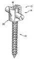
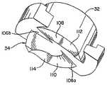
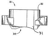
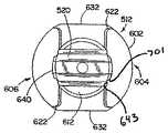
図1および2には、本発明の一形態による低寸法脊髄固定システム10が示されている。図示のように、脊髄固定システム10は、骨ねじ12の形をした骨アンカー部材と、概ね14で示された連結装置と、を含んでいる。連結装置14は、脊髄ロッド16の形をした細長い部材を、骨ねじ12に対して所定の位置に固定するように動作することができる。連結装置14は、圧縮またはカムロック部材18と連結部材20とを含み、これらは、ロッド16が概ね軸方向に脊柱に沿って延びるように椎骨に固定された骨ねじ12に対して、脊髄ロッド16を固定するように協働する。連結装置14、具体的にはカムロック部材18と連結部材20は、小形の構成を備えている。特に、カムロック部材18と連結部材20は、横方向に延在、具体的には図4を見ると最もよく分かるように、連結装置14によって骨ねじ12に対して固定された脊髄ロッド16の軸16aに直交して延在する軸線21によって示される方向に、非常に低い形状を備えている。“Detailed Description of Preferred Embodiments”
1 and 2 illustrate a low dimension
さらに具体的には、連結装置14の低寸法は、カムロック部材18を連結部材20に沿って前進させる必要なしに、脊髄ロッド16を有効にロックさせるカムロック部材18を有することによって得られる。なお、連結部材20は、脊髄ロッド16が通過する側面開口部24および26を有する本体22であって、カムロック部材18と協働して脊髄ロッド16を骨ねじ12に対してロックするねじ面またはカム面のない本体22を備えてよい。その代わり、カムロック部材18は、連結部材20に対して並進しないように固定され、好ましくは、ロッド16自体の外側湾曲面28と協働してロッド16をシステム10内のねじ12に対する所定の位置に固定する。 More specifically, the low dimensions of the coupling device 14 are obtained by having a
このため、カムロック部材18は、概ね環状に構成された本体30を有し、それは、頂面32と底面34との間に延在する環状の側面31を通って旋回軸21に沿う非常に短い軸方向範囲を有している。頂面32は、同様に構成された駆動工具を受けてキャップ部材18をロック解除位置とロック位置との間を旋回させる所定の構成を形成するように、互いに協働する駆動面部36を備えている。底面34は、図8および10を見ると最もよく分かり、以下に詳しく説明するように、カムロック部材18が旋回させられたときにロッド16の湾曲面にカム作用が働くように、段取りまたは輪郭付けされている。 For this purpose, the
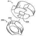
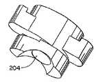
本発明の脊髄固定システム10についての低寸法の維持に関してはそれほど好ましくないが、図16〜18に示されているように、ロック部材18と脊髄ロッド16との間にサドル部材200の形をした中間クランプ部材を設けることができる。サドル部材200は、ロック部材18がそのロック位置に旋回させられたときに、ロック部材カム面34と協働するように構成された上部カム面202を有しており、これにより、ロッド16にクランプ留めするためにサドル部材200が下向きに軸21に沿って移動する。サドル部材は、ロッド面28の湾曲にほぼ一致する湾曲底面204を備えており、これによりサドル部材200は、ロッド16にカム作用を働かせずに、ロッド16と嵌ってそれを押す。カムロック部材18は中央開口部200を含んでよく、それは、サドル部材200から上向きに突き出る中央支柱208を受け入れて、カムロック部材18とサドル部材200を互いに適切な向きに維持する。 Although less preferred for maintaining low dimensions for the
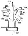
カムロック部材18と同様に、連結部材20も、その頂面38と底面40との間に比較的小さな軸方向範囲を有している。図11を見ると最もよく分かるように、連結部材の本体22は、ロッド開口部24および26によって互いに間隔を置いて配置されて向かい合う直立の壁42および44を含むU字形またはヨーク構成を概ね有しており、それらの開口部は、細長い構成を有して、連結部材本体22の頂部38に開放してよい。カムロック部材18は壁42および44に沿って下向きに方向21へ前進させる必要がないので、この方向におけるサイズを最小限に抑えることができる。一例として、壁42および44が連結部材本体21の頂部38と底部40との間を延びる長さまたは距離は、約13.47mmであってよいが、これに限らない。カムロック部材18は、頂部32と輪郭付けされた底部カム面34の最低点との間の軸21に沿った寸法が約5.08mmである。 Like the
図示のように、カムロック部材18の環状の本体30は、弧状の壁42と44との間の連結部材20の内部空間46に嵌るようなサイズを有している。壁42および44には、カムロック部材18と協働してカムロック部材18をロック位置に移動させるねじ面やカム面はない。特に、それぞれの連結部材壁42および44上に弧状面部42aおよび44aを含む連結部材20の内面48は、それらの間にカムロック部材環状本体30の外面31をぴったりと受け入れるようなサイズを有している。これらの表面部42aおよび44aはそれぞれ、ねじ面もカム面も有さず、したがって、カムロック部材本体30が軸21の周りを旋回するときに、カムロック部材本体30の案内面として働くに過ぎない。壁42と44にねじ山を設ける必要も、くぼんだカム面などを設ける必要もないので、連結装置14のサイズは、脊髄ロッド16の軸に沿って幅方向において最小限に抑えることができる。一例として、脊髄ロッド16に沿った連結装置の径方向幅は約10.03mmであってよいが、これに限らない。図7を見ると分かるように、各ガイド45を設けてよい。各ガイド45は、最初に、カムロック部材18を壁42および44に嵌めるように設けられている。 As shown, the
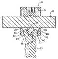
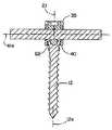
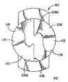
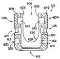
次に図3および4を参照すると、図示の脊髄固定システム10は多軸骨ねじ12を有し、その方向は、その長手方向軸12aが連結装置14の軸21に対して横方向に延びるか、または、それにほぼ揃うように、変えることができる。このため、連結装置18、具体的にはその連結部材20は、連結部材20の底壁52を貫通して延びる底部通し穴50を備えている。底部壁52は、内側に表面部42aおよび44aから中心軸21の方へ先細りするか、または湾曲する内面部54を含んでいる。内面部54の最下端56の所で内面部54を横切る直径は、骨アンカーねじ12のより大きな頭部58よりも小さいサイズを有している。さらに直径56は、ねじ頭部58から懸垂するねじ付きシャンク60が、そこを通って前進できるようにするのに十分な大きさを有している。このようにして、内面部54はねじ頭部58用のシート面として働く。あるいは、直径56は、シャンク60に対して過大なねじ山を備え、それによって、ねじシャンク60が容易に通過するのを可能にする。この例では、直径56は、シャンク60が容易に通過するサイズを有し、これにより、外科医は、手術時にねじ12および連結部材20を単一の構成部材として取り扱うことができる。さらに、過大なねじ山は、ねじをその向きにおいて多軸にするのを可能にする。あるいは、ねじ12を直径56に通過させることができ、cリングまたは半径方向ばねを連結部材20のすぐ隣でねじ12に取り付け、それによって、この2つを保持して、外科医が手術時にそれらを単一の構成部材として利用するのを可能にすることができる。 Referring now to FIGS. 3 and 4, the
通し穴50は、内面部54の中央を通って延び、連結部材20の底壁52の先細りまたは湾曲面部64で形成された、より直径の大きな底部62を含んでいる。先細り面部64は、連結部材20の中心軸21に対して外側に先細りしている56の所の通し穴50の最小直径から、連結部材20の底面40まで延びている。より大きな通し穴部62は、ねじ12が連結装置14に対して様々な異なる向きに旋回またはピボット運動するのを可能にする。例えば、図示の形態では、より大きな通し穴部62は、ねじシャンクが連結装置軸21の各側で200ピボット運動するのを可能にする。ねじ12がピボット運動すると、ねじ頭部58の外側弧状面66は、連結部材20の先細りシート面54に当たるか、またはシート面54上を移動する。脊髄ロッド16が連結部材20を貫通して脊柱に沿って上向きに延びるように、椎骨に固定された骨ねじ12に対する連結装置14の向きが決定された後、カムロック部材18がそのロック位置まで旋回させられる。ロック位置では、カムロック部材18がロッド16を脊柱に固定し、これにより、ロッド16は椎骨内に固定された骨ねじに対して固定され、骨ねじ頭部58が連結部材20内の骨ねじ頭部58用のシート54にクランプ留めされ、それによって連結装置14が骨ねじ12に対して移動しないように固定される。外側ねじ頭部面66は、ねじ頭部58とシート54との間のロック動作を改善する同心摩擦改善リッジまたはらせんねじ山67を含むように、構成することができる。 The through
引き続き図3および4を参照すると、好ましい図示の多軸脊髄固定システム10では、脊髄ロッド16が下向きに押され、小さなアンビルインサート68にクランプ留めされることが分かる。多軸ではなく、および/または後述のインサートを使用しない脊髄固定システムに、前述の低寸法連結装置14を使用できることに留意されたい。同様に、本インサート68は有利なことに、その連結部材にねじ山またはカムを使用するシステムに用いることができる。 With continued reference to FIGS. 3 and 4, it can be seen that in the preferred illustrated polyaxial
インサート68は、従来のシステムに用いられる骨ねじ頭部の湾曲面上での脊髄ロッド面28とのより良好な接触を維持するように、脊髄ロッド面28の下側に接触する上部アンビル面70を有している。インサート68は、ほぼ平坦であるか、あるいは半径方向に向けられた凹状経路または谷部をもつ上面60を有してもよく、これにより、インサート68は、最も近い経路まで回転して脊髄ロッド面28に当たるか、あるいは脊髄ロッド12によって圧縮されたときに変形して、脊髄ロッドを変形させずに経路を形成するカップまたは周辺リッジを有してよい。したがって、インサート68は、少なくとも湾曲ロッド面28との接触線を形成し、一方、脊髄ロッドを湾曲したファスナ頭部に嵌める従来のシステムは、脊髄ロッドにクランプ留めされるときに脊髄ロッドに点接触し、ロッド16をより容易に損傷させる恐れがある。 The insert 68 has an
また本インサート68は、非常に低い形状を備え、連結部材20内でインサートが占有する空間を最小限に抑えている。特に、骨ねじアンカー12は、そのねじ頭部58に形成された上部凹状くぼみ72を有して、ねじ頭部58のカップ状壁73を形成し、そのねじ頭部はインサート68が受け入れられる上向きに開放した空洞74を有する。インサート68は、凹状面72と同様な湾曲を持つ弧状底面76を有し、したがって、多軸ねじ12が連結装置14に対してその様々な向きに移動させられたときに、弧状底面76上を移動するかまたは滑ることができる。インサート68は、底面76の最下点と頂部平坦面70との間の距離が空洞74の深さよりもわずかに大きくなるようなサイズを有している。このように、平坦面70は、図5を見ると最もよく分かるように、ねじ頭部壁73の頂面80の所でねじ12の近位端78よりもわずかに上方に突き出て空洞74の周りに延びている。したがって、インサート68は、公称上のみ、連結部材20の内部空間46内のねじ頭部58の高さを高くし、前述のように連結装置14がその低寸法特性を維持するのを可能にしている。一例として、連結部材20の底部40と、ロッド16がインサート68にクランプ留めされた脊髄ロッド軸16aと、の間の距離は、約6.34mmであってよい。インサート68は、連結部材20または脊髄ロッド16よりも弾性変形度が大きく、したがって、ばね状特性がより顕著であることが好ましい。したがって、インサート68の材料は、連結部材20および脊髄ロッドよりヤング率が低く、それによって寸法公差の臨界条件を低減させることが好ましい。あるいは、コバルトクロムなどの材料をロッドよりも堅いインサート68に用いて、インサート68とロッドとの間のクランプ力を強めることができる。 Further, the insert 68 has a very low shape, and the space occupied by the insert in the connecting
好ましい図示の形態では、小形の低寸法インサート68は大きな下部82を有し、それは、弧状底面76を含み、より大きな下部82の中央から上向きに突き出て頂面70を有する上部84をもつ。したがって、頂面70は、軸21に直交する方向において底面76よりも狭く、これにより、インサート部82とインサート部84との間にショルダ面86が形成されている。低寸法インサート68の上述の構造によって、インサート68は、より大きな頭部82がねじ頭部58の凹状くぼみ面72に当たる逆きのこ状構成を備えている。 In the preferred illustrated form, the small low dimension insert 68 has a large
ねじ頭部58に形成された空洞74内にインサート68を維持するために、ねじ頭部壁73のステーク(staked)部88などの形をしたリテーナが設けられている。これらのステーク(staked)部88は、図3〜6に示されているように、ねじ12の近位端76の所で半径方向内側に延びてインサート68上のショルダ面86に干渉し、インサート68をキャビティ74内でのわずかの回転を可能にしつつ、インサート68を空洞74内にほぼ直立位置に保持されるようにする。回転という語が、ねじ頭部58内でのインサートのあらゆるピボット運動を含むものであることに留意されたい。図を見ると分かるように、インサート68は、連結部材20に対して固定されず、その代わりステーク(staked)部88によってねじ頭部内に保持されている。このため、インサート68はわずかな可動性、すなわち遊びを有することができ、インサート68はねじ12およびロッド面28とは無関係に移動することができる。したがって、インサート68は、ロッド面28とねじヘッド58との間でロッド面28およびシート自体に従い、自己整列能力を有することができる。 In order to maintain the insert 68 in a
前述のように、カムロック部材18は、そのロック位置に旋回させられるときに連結部材20に沿って並進しない。カムロック部材18を軸21に沿った方向に移動しないように固定しておくために、カムロック部材18は、環状本体30上の径方向において互いに向かい合う位置から半径方向外側に延びる半径方向フランジ90および92を備えている。フランジ90および92は、図6を見ると分かるように、連結部材壁42および44に形成されてフランジ90および92に対応して構成されたくぼみ94および96に受け入れられる。くぼみ94および96は、カムロック部材18がそのロック解除位置とロック位置との間を旋回するのを可能にするために、半径方向フランジ90および92と同様に軸21の周りに延びる弧状構成を有している。フランジ90および92は、カムロック部材18がそのロック位置の方へ旋回させられたときにくぼみ94および96に受け入れられる。カム面34がロッド面28にカム作用を働かせている状態で、フランジ90および92にほぼ一致するくぼみ94および96内のフランジ90および92は、カムロック部材18が脊髄ロッド16から上向きに離れる方向へ移動するのを防止し、その代わりに脊髄ロッド16を下向きに押してインサート68に接触させ、それによってねじ頭部58、具体的には外側頭部面66を連結部材20のシート面54にクランプ留めさせ、したがって、連結装置14を骨ねじ12に対して固定し、脊髄ロッド16を脊柱に対して固定する。 As described above, the
カムロック部材18によって、ねじ頭部58と連結部材20の底壁52との間、特にそれぞれの接触面66および54同士の間に掛けられる下向きのクランプ力により、連結部材壁42および44を広げることができる。したがって、フランジ90および92はそれぞれ、軸21に沿って延びる遠位部98および100も備えている。この例では、遠位部98および100は、半径方向フランジ90および92の遠位端から上向きに曲げられるように示されている。ただし、遠位部98および100は、下向きに軸21に沿った方向へ延びるように同様に構成することができる。くぼみ94および96はそれぞれ、連結部材壁42および44の軸21に沿って上向きに延び、それぞれの半径方向フランジ90および92上の上向き遠位部98および100を受ける部分102および104も含んでいる。フランジ部98および100がくぼみ部102および104に受け入れられた状態において、カムロック部材18を旋回させるロック動作中の壁42および44の広がり動作は、抵抗を受ける。 The
前述のように、カムロック部材は、脊髄ロッド16の湾曲カム面28にカム作用を働かせる輪郭付けされた底部カム面34を有している。カム面34は、図8および10に最もよく示されている。図示の好ましい形態では、カム面34は、脊髄ロッド16に対する作用に関連して形成された3つの異なる領域を構成するように輪郭付けされている。第1の凹状領域106は、ロック解除位置で実質的にロッド面28と嵌め合うように構成されている。凹面領域106は、カムロック部材本体30の底部を横切って延び、半径方向フランジ90および92に揃えることができる。したがって、半径方向フランジ90および92は、カムロック部材本体30の底部よりもわずかに上方に配置されて、カムロック部材18がそのロック解除位置にある状態でカムロック部材本体30の下方に延びる脊髄ロッド湾曲面28に対応する。この位置では、フランジ90および92は、そのくぼみ94および96には受け入れられず、または完全には受け入れられない。 As described above, the cam lock member has a contoured
凹面領域106の径方向において互いに向かい合う部分106aおよび106bは、ロック解除位置にあるカムロック部材18が回転しても、そのわずかな初期旋回作用だけではカム作用が働かないように設けられている。脊髄ロッド面106が表面部106aおよび106bに揃えられた状態では、脊髄ロッド16は、依然としてカムロック部材18の下方に緩く受け入れられ、カムロック部材18のカム作用を受けない。有利なことに、脊髄ロッド16はカムロック部材18の下方に捕捉され、外科医は、最終的にカムロック部材18をロックする前に、より自由に操作を行うことができる。カムロック部材18を引き続き旋回させると、カム作用は斜面領域108および110の所から開始、それらは、カム底面34上で径方向において互いに向かい合い、互いに隣接する表面部106a、106bから下向きに、方向21に沿って突き出る。斜面領域108および110は、カムロック部材18が旋回軸21の周りをロック位置の方へ旋回させられたときに、ロッド16が徐々に下向きに方向21へ押されるように構成されている。したがって、ロック解除位置では、底部カム面34上のこれらの斜面領域108および110は、下向きに脊髄ロッド16の各側に沿って延び、有利なことに脊髄ロッド16の各側の空間を占有し、したがって、連結部材20内のカムロック部材18によって占有される空間を最小限に維持して、連結装置14全体に低い形状に維持する働きをする。 The
引き続きカムロック部材18をロック位置の方へ旋回させると、ロッド面28は、それぞれ斜面領域108および110に隣接する径方向において互いに向かい合う概ね平坦な表面領域112および114に接触する。他の形態では、表面領域112および114は、ロッド12が受け入れられるくぼみを構成する谷状であってよい。表面領域112および114は、前述の斜面108および110とは異なり、軸21に対して傾斜しておらず、カム面34をロッド面28に接触させる最下点になっている。ロッド面28が表面領域112および114に接触する程度にカムロック部材18を旋回させると、図1および6に示されているように、カムロック部材18はその完全ロック位置になり、カムロック部材フランジ90および92は、それに対応するヨーク壁くぼみ94および96に完全に受け入れられる。完全ロック位置に達した後、引き続きカムロック部材を同じ方向に回転させようとしても、それぞれ表面領域112および114に隣接する当接面領域116および118によって防止される。これらの当接面116および118は、表面領域112および114からさらに下向きに方向21へ延びている。 As the
したがって、図示の好ましい段取りされたカム面34は、脊髄ロッド16に対してカム作用およびロック作用を働かせるいくつかの段を構成する。図示のように、カムロック部材18は、ロッド面28が斜面108および110に達する前に、ロック解除位置から約20°回転させることができる。この点で、ロッド16は下向きにカム作用を受け、ロッド面28が平坦なロック面112および114に達する前に、カムロック部材をさらに60°旋回させることができる。次いで、ロッド面28が停止面116および118に当たり、カムロック部材18がその完全ロック位置になる前に、カムロック部材18をさらに20度旋回させることができる。したがって、完全ロック解除位置から完全ロック位置に至るまでに、カムロック部材18を約100°回転させる必要があり、カム作用が始まる前に20°の遊びが設けられ、完全ロック位置に至るまでの最後の80°の回転に渡ってロッド16のカム作用が生じる。 Thus, the preferred stepped
具体的には、前述のように、キャップカムロック部材18は、頂面32にくぼまされた駆動面部36を含んでいる。図2を見ると最もよく分かるように、駆動面部36は、中心軸21から半径方向外側に延びて、同様なローブを有する駆動工具を受け入れる複数のローブ(lobes)を備えてよい。ローブ駆動面部36は、駆動工具とカムロック部材18との間の面接触およびトルク伝達の面積を大きくする。 Specifically, as described above, the cap
骨ねじ12については、図15を見ると分かるように、ねじ頭部58が周辺駆動面120およびくぼみ状切欠き122を備えており、それらは、ねじ頭部の近位端78に形成されて、その頂面80にくぼまされるかまたは切り欠かれている。このように、前述のようにアンビルインサート68がねじ頭部空洞74内に位置して、そこからわずかに突き出ている間に、切欠き122に嵌め込まれる周辺プロングを持つ駆動工具を利用することができる。 For the
図1および11〜13を参照すると、ヨークカプラ壁42および44がそれぞれキー長穴124および126を備え、長穴124および126が、壁42および44を貫通して延びるより大きな中央通し穴128および130を有することが分かる。これらの長穴は、脊髄ロッド16を連結部材20に挿入するのに用いられる装置、例えばロッドパースエイダ(rod persuader)上のアームによって、連結装置14を保持するのを可能にする。アームは、長穴124および126内に配置されて通し穴128および130内に延びる係合端部を有してよい。 Referring to FIGS. 1 and 11-13,
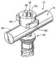
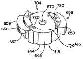
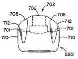
次に図19〜44を参照すると、本発明の他の形態による脊髄ロッド16を固定する低寸法脊髄固定システム500が示されている。図19および20を見ると分かるように、システム500は、ねじ502としての骨アンカー部材と、脊髄ロッド162を骨ねじ502に対して固定する連結装置504と、を含んでいる。連結装置は、単体ヨーク512の形をした連結部材と、アンビル516の形をしたインサートと、キャップ518の形をしたカムロック部材と、ばねクリップ519の形をしたコネクタ部材と、サドル520の形をしたクランプ部材と、を含んでいる。固定システム500は、図20を見ると最もよく分かるように、キャップ518とヨーク512が、連結装置504によって骨ねじ502に対して固定された脊髄ロッド16の軸16aに対して横方向であり、具体的には、軸16aに直交して延びるヨーク軸線21によって示されている方向に非常に低い形状を備えている。 Referring now to FIGS. 19-44, a low dimension
ねじ502は、ヨーク512を貫通するように向けられ、ヨーク512を骨または骨折片に取り付ける。ねじ502は、くぼみ554を持つ頭部536を有し、くぼみ554はアンビル516を受け入れる。脊髄ロッド16は、ヨーク512の内部空間または溝601内に受け入れられて、アンビル516上に位置している。ねじ502は、多軸ねじであることが好ましく、アンビル516は、ねじ502の頭部536内を移動することができる。したがって、システム500が固定される前に、ねじ502はヨーク512に対して移動することができ、これにより、それらのそれぞれの軸21および544が必ずしも互いに整列しないように、ヨーク512とねじ502を互いに対する異なる向きをとるように選択的に位置させることができ、アンビル516は、ねじ502に対して移動しかつピボット運動または回転することができ、したがって、前述のアンビル68と同様に、ロッド16の外面28によってアンビル自体の向きを定めることによってアンビル516を適切に位置させることができる。 A
ロッド16は、キャップ518およびサドル520によってヨーク512内に固定またはロックされている。後述のように、キャップ518の回転は、ヨーク512のくぼみ642内にキャップ518を固定する機能と、サドル520をロッド16に押し付けてサドル520とアンビル516との間にロッド16をロックする機能と、の2つの機能を有している。サドル520とキャップ518は、組立て時に二重プロング式ばねクリップ519の形をした異なるコネクタによって固定されている。 The
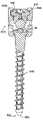
図21、22には、骨ねじ502が示されている。骨ねじ502は、遠位端532の所の先端530と、ねじ頭部536を含む近位端534と、雄ねじ540を含みねじを骨または骨折片に打ち込み固定するシャンク538と、頭部536とシャンク538が当たる首部542と、を含んでいる。ねじ502は、その中央長手方向軸544の周りを回転することによって打ち込まれる。ねじの先端530は、公知のように、セルフタッピン構造やセルフドリリング構造のような様々な構成を備えてよい。後述のように、ねじ502は多軸であることが好ましく、頭部536は、首部542の所では径方向においてシャンク538よりも大きい。ねじ502の多軸特性によって、ねじ502を、骨に適切に固定するのに望ましい向きに骨に固定することができ、一方、ヨーク512を、ねじ502に対して、ロッド16をヨーク512内に位置させるのに望ましい向きに向けることができる。 A
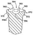
ねじの頭部536は、ねじ頭部536の周辺外面552に当たる弧状またはわずかに斜面の頂面550を有している。ねじ頭部536の周辺外面552は、概ね弧形状または球形状570を有している。形状570には、一連の同心リッジまたは円形溝572が切り込まれている。上述のように、ねじ502は多軸であり、したがって、ヨーク512に対するその向きを厳密に位置させることができる。連結装置504をねじ502に固定すると、溝572がヨーク512の内側に噛み合うかまたは食い込んで、ねじ502がヨーク512に接触して所望の位置に固定される。一例として、溝572の幅は、ヨーク512に十分な把持強度またはパーチェス(purchase)を与えるように約0.012インチであってよい。 The
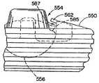
頂面550は、アンビル516を受け入れるために形成された上向き開放のくぼみ554を含んでいる。図24〜27を見ると分かるように、くぼみ554は、小さなアンビル516がくぼみ554内に配置されたときに、アンビル516が移動するのを可能にするようなサイズを有するように構成された、弧状または好ましくは球状の最下面部556を有している。このため、アンビル516は、最下面部556上に支持されかつ最下面部556に接触して滑ることができる底面558を有している。さらに、くぼみ554は、径方向において互いに向かい合う2対の切欠き560を有し、各対は他方の対から垂直方向に向けられて、くぼみ554内のアンビル516に干渉せずに、同様に構成されたドライバのプロングを受け入れる。頂面550は、くぼみ554の開口部の所および各切欠き560間に配置された短いタブ562の形をしたリテーナまたはステーク(staked)部を含んでいる。くぼみ554にアンビル516を配置する前に、タブ562は頂面550から上向きに軸方向へ延び、したがって、タブ562はアンビル516の挿入を妨げない。アンビル516がくぼみ554内に配置された後、タブ562は、撓んで半径方向に延びてアンビル516に干渉し、一方、アンビル516は、依然としてくぼみ554内を移動できるが、タブ562によってくぼみ554内に捕捉することができる。組立て後、熱またはその他の処理を利用して、曲げられたタブ562内の残留応力を緩和することができる。
アンビル516は、シート554の最下部556に接触する概ね弧状または球状の底面558を持つ底部580を有している。したがって、アンビル516は、くぼみシート554内でピボット運動または回転することができる。アンビル516は、中央をアンビル底部580から頂面584まで上向きに延びるシート部582をさらに含み、アンビル部580とアンビル部582との間に横方向ショルダ面585が位置している。図27を見ると最もよく分かるように、アンビル516がくぼみ554内に直立状態で位置するとき、曲がったタブ562とアンビル横方向面585との間に隙間間隔587が存在する。この隙間間隔587と、くぼみ554内を概ね上向きに延びるアンビル上部582のより狭い幅と、によって、アンビル516は、くぼみ554内をトグル運動またはピボット運動することができ、アンビル面585は、1つまたは複数のタブ562に当たるまでくぼみ面556上を滑る。前述のアンビル68と同様に、アンビル底部580は、上部582と比べて大きくなっており、したがってシート部582は、くぼみ554内およびアンビルショルダ部585とタブ562との間の空間587内を移動することができる。
シート部582は、シート部に対する圧縮応力が底部580まで分散され、一方、頂面584の外側縁部584aが損傷を受ける可能性が最小限に抑えられるように、円錐台状であることが好ましい。前述のアンビル68と同様に、アンビル底部580は、上部と比べて大きくなっており、したがってシート部582は、くぼみ554内およびアンビルショルダ面585とタブ562との間の空間587内を移動することができる。 The
ロッド16をヨーク512内に挿入すると、ロッド16の側面28が前進してアンビル516に接触する。骨ねじ502がたわむか、斜めになるか、または固定されて、その中心軸544がヨーク中心軸に一致しないかまたは揃わない場合、アンビル516は最初、同様の方向に撓むかまたは傾く。ロッド16が固定されてアンビル516に押し付けられると、くぼみ554内でピボット運動可能なアンビル516が移動し、ロッド16とくぼみ554の底面部556との間に必要な距離が最小限に抑えられる。アンビル頂面584は平坦であり、一方、底面558は球形であるので、頂面584から底面558までの最も短い距離は、幾何学的中心588を通って底面558の中心590aまでの距離である。 When the
本明細書で論じるように、低い形状を有するには、ねじ頭部536の頂面550の上方に位置している間に、アンビル516の高さを最小限に抑えることが好ましい。アンビル頂面584は、骨ねじ502の角度または撓みのために斜めになるかまたは撓んだときに、頂面584の少なくとも一部が、ヨーク512内のアンビル516の方へ前進させられているロッド16に接触するようなサイズを有している。したがって、アンビル516は、アンビル頂面584に接触したロッド16がアンビル516を移動させて、上述のように接線方向におけるアンビル516の最小限の高さをロッド16の表面28に揃えるときに、自己復元する。 As discussed herein, to have a low shape, it is preferable to minimize the height of the
多軸ねじ502はヨーク512に挿入されて骨に固定され、ロッド16はアンビル516の頂面584に接触する。ヨーク516に対するねじ502の向きがピボット運動できるため、アンビル516はくぼみ554内でピボット運動することができ、したがって頂面584は、ロッド16の概ね円筒形の外面28に対して接線方向に位置したままである。一般に、アンビル516とねじ頭部536は、具体的にはそれらのくぼみ554は、ねじ502がヨーク512に対してその最大限まで、例えば、軸21から20°ピボット運動した状態で、アンビル頂面584が頭部上面550の所でカップ状頭部壁536aの頂部をわずかに越えて延びるように、互いに対するサイズを有している。具体的には、前述のように、アンビル底部580は、図24に示されているように半径589を持つ概ね球状の構成を有するように、その底面558を湾曲させることができる。底面558が弧状くぼみ面556内をピボット運動する際、半径589はアンビル516の概ね回転中心588から延びる。アンビル516は、ショルダ面585およびシート部582を有するように概ね球状の構成部材で作られている。したがって、回転中心588からアンビルシート面584までの高さ距離は、半径589の長さより少なくともわずかに短い。一例として、高さ距離586は約0.043インチであってよく、半径589は約0.0625インチであってよく、したがって距離586は半径よりも約0.0195インチ短い。アンビル頂面584の高さ586を著しく高くした場合、アンビル頂面584の幅を大きくしなければならず、それによって、アンビル516がタブ584に接触する際の傾きまたはたわみの度合いが小さくなるため、ねじ502の多軸運動が制限される。アンビル頂面584の高さ586を著しく低くした場合、ロッド16がアンビル頂面584に接触する際に必ず最初にねじ頭部536に接触することになり、この事象は、たわみ角度が大きくなるにつれてより深刻化する。 The
したがって、アンビル516と、内部を延びるタブ562を含むくぼみ554と、の構成によって、アンビル516はロッド16の位置に従うようにピボット運動することができ、アンビル516の自己復元を推進することができる。さらに、表面584および558間の高さ586を含むアンビル516のサイズは、頂面584が完全に球形のねじ頭部の頂面より低くて、ヨーク512内のねじヘッド536およびアンビル516を含むアンビル組立体の寸法を最小限に維持するように、サイズが選択される。すなわち、ねじ頭部536が球形である場合、ねじ頭部536の頂部の高さはアンビル516の頂面584よりも高くなり、システム500の全高が高くなる。連結装置504がそのロック状態にある場合、アンビル516の頂面584はわずかに変形することができ、それによって、ロッドの外面28にぴったりと接触しかつ整合するくぼみが形成される。変形によって、アンビル516とロッド16は、ほぼ同一平面を形成するように、線接触ではなく面接触する。アンビル516の底面558は、アンビル底面558とシート554との間の摩擦を最低限に抑えるのを助ける小さな平坦部590を含んでいる。 Thus, the configuration of the
上述のように、ねじ502はヨーク512に挿入される。図28〜32を見ると分かるように、ヨーク512は、より大きなベース部600と、より大きなベース600から延びて、間にロッド16を受け入れる溝601を形成する互いに向かい合う一対の側壁部604、606によって形成される概ね円筒形の外面602を含む形状と、を有している。溝601は、例えば、PEEKなどのポリマーで作られ、ロッド16と溝601との間の低摩擦接触を推進するライナを有してよい。溝601を含むくぼみ608が、垂直軸21によって壁604、606の間に形成されており、くぼみ608は、ねじ502が挿入されるヨーク512の底部またはベース600の通し穴612を含んでいる。通し穴612は、上述の連結部材20の通し穴50として構成することができ、内部のねじ502の低摩擦多軸移動を推進するPEEKなどのポリマーライナを含んでよい。 As described above, the
図1および11〜13に示されているのと同様に、ヨーク壁604、606の外面602はそれぞれキー長穴124および126を備え、長穴124および126は、壁604、606を貫通して延びているより大きな中央通し穴128および130を有している。長穴は、脊髄ロッド16をヨーク512に挿入するのに用いられる装置、例えばロッドパースエイダ上のアームによって、連結装置514を保持するのを可能にする。アームは、長穴124および126内に配置されて通し穴128および130内に延びる係合端部を有してよい。 Similar to that shown in FIGS. 1 and 11-13, the
ヨーク512の外面602は、めくら孔または穴650も含んでいる。図32を見ると最もよく分かるように、めくら穴650は、内部くぼみ605内には延びず、その代わりにヨーク512の薄壁部652の所で終わっている。ねじ502およびそれに固定されたアンビル516を通し穴612に挿入した後、各めくら穴650に隣接する薄壁部612がくぼみ608内に変形し、これにより、ねじ502とアンビル516の部分組立体は、ヨーク512から引き出すことができず、したがってヨーク512に組み付けられたままである。ねじ502をヨーク512内に保持すれば、外科医は、ねじ502、ヨーク512、およびアンビル516を単一の部材または組立体として取り扱うだけでよくなる。 The
好ましい図示の形態では、ヨーク512は、後述のように高強度単体構成を有している。一体的な各側壁部604、606は、頂面620、端面622、および内面624を有している。各壁604、606の内面624は、概して、反対側の壁上の表面の鏡像である。壁604、606は互いに協働して、各内面が頂面620から下向きに延びる領域内で垂直方向に向かい合う一対の脚部628を有する2つのU字形内面626を形成している。それぞれの一対の脚部628は、端部628を相互に連結する概ね半円の部分630に当たる。表面626の外側において、ヨーク512の円筒形の外面602は、壁604、606の端面622を形成するように切り取られ、かつベース600上に端面632を形成するように切り取られている。ヨーク512の端部を切り取ると、軸方向21に対して横向きの幅方向におけるヨーク512の全体的なサイズが小さくなる。図28および31を参照すると、ベース600の端面632同士の間の寸法が壁604、606の端面622同士の間の寸法よりも大きいため、端面632と端面622との間にショルダ634が形成されている。ベース部600が壁604および606の下端部の所で大きくなっていると、ロッド16がヨーク512の底端の近くの湾曲面部630にクランプ留めされる応力集中が最も高くなる領域で、ヨーク512の強度を高くすることができる。ベース部600から上向きに延びている側壁部604および606に沿ってヨーク512を切り取ると、前述のように、ヨーク512の幅がその軸方向長さの大部分に渡って最小限に維持される。 In the preferred illustrated embodiment, the
壁604、606の内面624は、それぞれ、U字形内面626同士の間を延びる概ね円筒形の構成を有する表面640を含んでいる。円筒形の表面640と内面626は、一定の断面を有する側面において周方向に延びる内側くぼみ642を形成している。小さな突起またはナブ(nubs)の形をしたガイド643は、図28に示されているように、くぼみ642の上方における内面626上に配置されている。図29に示されているようにサドル520をヨーク512に挿入する際、ガイド643は、後述のようにサドルをヨーク内に適切に位置決めするのを助ける。さらに、ガイド643は、キャップ518を旋回させる際に、キャップ518のそれぞれの異なる回転位置を定める戻り止めとして働く。上述のカムロック部材18と同様に、キャップ518は、外面645を持つ概ね円筒形の本体部644を有しており、その外面は、外面645の周りに周方向に間隔を置いて配置された概ね垂直方向の弧状のへこみの形をしたいくつかのくぼみを含む。へこみ647は、ナブ戻り止め643がへこみ647に嵌りかつ外れるときに、キャップ518がヨーク512内でどれだけ旋回させられたかを外科医に触覚によって示すように、戻り止め643と協働する。例えば、キャップ518がそのロック位置にあるとき、戻り止め643とへこみ647は、キャップ518がその完全ロック位置に旋回、例えばロック解除位置から100°の位置まで旋回させられるときに、カチッという音が所定回数発生するように、間隔を置いて配置することができる。 The
くぼみ642は、概ね水平方向に延びてキャップ518を受け入れ、具体的には、前述のフランジ90および92、ならびに対応するくぼみ94および96と同様に、ヨーク512に対応して構成されたくぼみ642に嵌るキャップ518の一対の半径方向フランジ656を受け入れる。半径方向フランジ656とくぼみ642は、ヨーク512が旋回させられるときに、キャップ518がヨーク512に沿って軸方向に移動するのを防止し、したがって、キャップ518とサドル520との間に発生するカム作用は、サドル520を軸方向に脊髄ロッド16の方へ移動させ脊髄ロッド16に接触させるに過ぎない。各フランジ656は平坦な引込み斜面657を含み、それは、キャップ518がそのロック解除位置にある状態で、フランジ656が側壁部604と606との間に形成された長穴から旋回させられるときに、フランジ656の案内を助け、フランジ656を移動させてそのそれぞれのくぼみ642に挿入する。しかし、くぼみ642の表面とフランジ656との間に、サドル520の下面700をキャップ518に対して移動させるカム作用は起こらない。後述のように、カム作用が発生するのは、キャップ518の底面704とサドル520の頂面702との間だけである。 The
半径方向のフランジ656は、その遠位端659の所に上向き部658も含んでおり、くぼみ642は、それぞれのヨーク壁604、606において上向き軸方向に延び、上向きフランジ部658を受け入れるための対応する部分649も含んでいる。フランジ部658が、対応するくぼみ部649に受け入れられると、キャップ518の旋回によるロック動作中のヨーク壁604、606の広がり作用が抵抗を受ける。 The
図41〜44に示されているように、キャップ518とサドル520は、それぞれ、クリップ519が通って延びる中央開口部670,672を形成している。キャップ開口部670は、下部670aと、下部670aよりも大きな直径まで段階的に開放される上部670bと、にセグメント化されている。環状のショルダシート面674は、キャップ開口部670の下部670aと上部670bとの間の遷移部に位置している。上部670bは、キャップ部材518の駆動ソケット内のくぼんだ底面671にも開放されている。 As shown in FIGS. 41-44,
図36および37を参照すると、クリップ519は、環状のベース部680と、2つの弾性プロングまたはステム680a、680bと、を含む、それらのステムは、クリップ軸683に沿ってベース部680から上向きに突き出て、それらの間の軸方向に延びる隙間682によって間隔を置いて配置される。各ステム680a、680bは、上向きのカム面684を含むフランジ681aおよび681bを有する自由端で終わっており、それらのフランジは、クリップ軸方向683に対して斜面を成すかまたは傾斜、あるいはクリップ軸683に対して湾曲していてもよい。カム面684は、クリップ519を開口部670および672に挿入するのを助け、対応する下部停止面688は、クリップ軸683に垂直に延びるプロングフランジ付き端部681aおよび681bの所に設けられて、クリップ519がうっかり開口部670、672から外れるのを実質的に防止する。 36 and 37,
サドル520の中央開口部678は、上部672aと下部672bも含んでいる。下部672bは、サドル520の凹状底部700に開口し、上部672aよりも大きな直径を有し、したがって、下部672bと上部672aとの間に環状のショルダ面672が延びている。より大きな下部672bは、クリップ519のベース部680が表面672cに干渉しながら下部672bに嵌って保持されるようなサイズを有している。開口下部672bの直径は最小限に維持され、ロッド16上のサドル面700の接触表面積が広くなることが好ましい。開口上部672aは、キャップ開口部670のより小さな下部670aと同様の直径を持つようなサイズを有してよい。 The central opening 678 of the
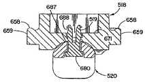
キャップ部材518とサドル部材520を組み立てる場合、まず、プロング自由端681aおよび681bをより大きな下部開口部672bに挿入することによって、ばねクリップ部材519をサドル開口部672に軸方向に挿入する。引き続き軸方向に挿入すると、カム面684がショルダ面672cに接触してカム作用を働かせ、ばねプロング680aおよび680bを互いに向かう方向に弾性的に押して、それらの間の隙間682を無くす。プロング680aと680bが押し付けられると、カム面684の横方向外側縁部684a同士が、開口部670aおよび672aの直径よりもわずかに短い距離だけ離して配置される。これによって、より小さな直径を有する開口上部672aを含む開口部672に、クリップ部材519を引き続き挿入することができる。開口下部672bの直径に対して非変形時のプロング上縁部684a同士を横切る距離に応じて、サドル面700にもカム作用を働かせ、それに伴ってプロングをある程度変形させることができ、クリッププロング680aおよび680bを開口下部672aに嵌め込むことができる。プロング端部681aおよび681b、特にそのプロング面688が開口上部672aを離れた後、クリッププロング680aおよび680bは、その最初の非変形状態に戻ってサドル520の上面702と向かい合い、したがって、プロング680aと680bをまとめる力を掛けないと、クリップ部材519とサドル部材520は組み付けられたままである。 When assembling the
組立てプロセスを完了するには、次に、プロング端部681aおよび681bをキャップ開口部670、特にそれより小さな下部670aに、軸方向に挿入する。したがって、カム面684は、キャップ518の下面687bに対して中央開口部670の周りにカム作用を働かせ、それによって弾性ステム680a、680b同士が押し付けられ、それらの間の隙間682が無くなり、クリッププロング680aおよび680bを開口部670aに挿入するのが可能になる。クリップカム面684がキャップ開口部670の下部670aを通過した後、ステム680a、680bは、弾性的にその非たわみ位置の方に戻る。プロング端部681aおよび681bが開口部670から出た後、プロング680aおよび680bはその非変形状態に戻り、各停止面688は、キャップ面671に面し、かつ図42に示されているように、互いに連結された構成部材、すなわちキャップ518とサドル520とクリップ519との間に遊びが生じるように、キャップ面671から間隔を置いて配置される。キャップ518をそのロック位置の方へ旋回させると、サドル部材520が、クリップ部材519をその軸方向に移動させるロッド16の方へ駆動されるので、プロング端部681aおよび681bが開口上部670bに再び進入し、クリップベース680上の表面672cがシート面674に当接させられた停止面688に接触しているために、ばねクリップ部材519が軸方向にサドル部材520と一緒に移動し、キャップがそのロック位置に旋回する間に、クリップ519がうっかり開口部670、672に引込まれるのを実質的に防止する。 To complete the assembly process, the prong ends 681a and 681b are then inserted axially into the
クリップ519のステム680a、680bは、中央二重カム斜面800を含む中間カム部をさらに含んでいる。まず移植の準備時に、クリップ519は、図41および42に示されているように、サドル520がキャップ518に接触またはすぐ隣に位置するように、クリップベース680がサドル開口ショルダ面672cに接触させられる小形組立て構成に、キャップ518とサドル520を保持する。この小形構成では、二重斜面800はキャップ開口部670内に配置され、キャップ518をサドル520に接触させて保持する。ステム680a、680bの末端681a、681bの所の停止面688は、外科医が患者の脊髄から固定システム500を取り外すときなど、キャップ518およびサドル520がヨーク512から取り外される場合に、キャップ518がサドル520と組み立てられたままになるのを可能にする。 The stems 680 a and 680 b of the
特に、カム斜面800は、横方向に共通する外側縁部806の所で当たる下部カム面部802と上部カム面部804とを含んでいる。図37を参照すると、中間外側カム面縁部806が、684aの所の遠位上部プロング縁部を横切る距離とほぼ同じサイズを有することが分かる。図示のように、カム面802は、上向きに縁部806まで延びるにつれて軸683から離れる方向に傾き、一方、カム面804は、縁部806から上向きに延びるにつれて軸683の方へ傾いている。したがって、組立て時に、上部カム面804は、プロング680aおよび680bが、キャップ・サドル開口部670および672に嵌るように、互いに向かう方へ移動するのを助ける。同様に、キャップ518が旋回してロッド16上のサドル520が緩む際、上部カム面804によって、サドル520はクリップ部材519と一緒に軸方向上向きに引っ張られる。 In particular, the
キャップ518とサドル520が図42に示されているように組み立てられると、縁部806がサドル開口上部670b内に配置され、これにより、下部斜面802が摩擦によって開口下部670aの周りの表面上に位置し、サドル上面702をキャップ底面704に接触させるかまたはキャップ底面704のすぐ隣に保持する。さらに、カム面802の斜面または傾斜の向きによって、サドル520を、下向き、または軸方向に固定された旋回するキャップ部材518から離れる方向に駆動することができる。キャップ部材518をそのロック位置の方へ旋回させると、カム面802は、カム作用によって開口部670aの周りの表面に支持され、弾性プロング680aおよび680bが互いに押し付けられ、それによって、縁部806を含むプロングを開口部670aに嵌め込むことができる。しかし、カム面縁部806と停止面688との間の軸方向距離は、サドルの下部開口部670aの軸方向範囲よりも大きく、したがって、縁部806が開口部670aから離れた後、プロング680aおよび680bはその非変形構成の方へ弾性的に戻ることができ、停止面688は開口部670内のシート面674に干渉する。さらに、サドル部材520が軸方向下向きに移動すると、図44に示されているように、カム面縁部806が開口部670および672から露出される。 When the
図38〜40を見ると分かるように、サドル520は、その側面710に沿って溝710を有している。上述のように、図29を見ると分かるようにサドル520をヨーク512に挿入すると、溝701がヨーク512のナブガイドまたは戻り止め643を受入れ、サドル520がヨーク512内で適切に位置決めされかつ挿入され、ヨーク側面710がヨーク側壁部604および606の内側に沿って案内される。サドル520は、図38を見ると分かるように、サドル520をヨーク512に出し入れするのを助ける先細りした端部703をさらに有している。 As can be seen in FIGS. 38-40, the
さらに、サドル520の底面700は、相補的にロッド16に接触するように凹状になっている。サドル520は異なる形状の上面または頂面702も含んでおり、それは、キャップ518における異なる形状の底面704と協働するように構成され、カム作用によってサドル520の底面700を移動させ、それをロッド16に接触させてロックする。具体的には、サドル520の頂面702は概ね水平方向でほぼ平坦な部分706を有し、それは、ロッド16の軸524の方向に概ね直交する方向へ、各ヨーク側壁部604および606に向かって長さ方向に延びる。なお、サドル520は細長いカム面702を有し、それは、前述のシステム10のように、ロッドの表面によって形成される細長いカム面から90°に向けられている。 Further, the
図44を見ると分かるように、サドル520をキャップ518とのロック位置に設置すると、キャップとサドル520との間の力が、概ねサドル頂面702の横方向位置709の所に位置する底部カム面部820を通して伝達される。サドル520を、底面700に受け入れられたロッドの横に位置させると、サドル520は、その横方向位置を通して分解される力を、ロッド16の局部領域の表面接触領域に分散させることができる。これに対して、サドル520をロッド16の長手方向軸16aに沿って向けるか、または図示の状態から90°移動させた場合、横方向端部709を通して力を供給するサドル520は、サドルに嵌められたロッド16の表面の頂部に沿って配置された一対の局部領域を通して力を伝達する。このような構成は、ロッド16に対して擦過、または損傷および磨耗を生じさせ、ロッドが故障したり、ロッドおよびサドルの各部がせん断されたりする恐れがある。さらに、このような構成は、患者が動くことを許可されて、システムに応力がかかるときに、システムの性能にとって望ましくない剛性をロッド16のある長さに加える。 44, when the
頂面702は、平坦部706の横に位置して平坦部706に続いているほぼ平坦な2つのカム側面708も含んでいる。各カム面708は、平坦部706から下向きにサドル520の下側面710まで傾いている。カム面708同士の間から下側面710までの縁部712はわずかに丸くなっており、それによって、キャップ518は縁部712に容易にカム作用を働かせることができる。したがって、ファセット状カム面(faceted cam surface)702は、ロッド軸16aに概ね垂直な軸の周りを延びている。 The
キャップ518の底部カム面704を受け入れるように、頂面702を上向きに弧状に傾斜させこともできるが、平坦部706は、カム作用中に応力を分散させることが好ましい。具体的には、丸いかまたは弧状のカム面では、弧状カム面の最初の部分におけるカム接触によって顕著な量の仕事を行う必要があり、そして、カム接触が弧状カム面の頂部まで移動するにつれて、その仕事量が減っていく。これに対して、平坦部706のような概ね平坦な表面では、キャップ518の嵌め合いカム面704が平坦部706上に配置されるので、仕事は平坦部706に沿ってより均等に分散される。 Although the
キャップ518をサドル520に対して回転させると、キャップ518の底面704がサドル520の頂面702にカム作用を働かせ、これにより、キャップ518の底面704がサドル520の頂面702に接触し、サドル520を軸方向にキャップ518から離れる方向へ移動させて、脊髄ロッド16にぴったりと接触させる。なお、キャップ自体518が、垂直方向にヨーク512に沿ってヨーク512内に移動することはなく、その代わり、キャップ518は、脊髄ロッド16をロックするために旋回させられるときにキャップ518の中央垂直軸の周りを回転するに過ぎない。前述のように、ベース部680と停止面688との間のクリップ519の長さ690は、特にキャップ518とサドル520との間のこの移動動作を可能にするように構成されている。 When the
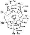
図34に示されているように、キャップ518の底面704は、上記で論じられかつ図8および10に示されているカムロック部材18と同様に段取りされたカム面である。ただし、図34に示されているキャップ518のロック解除位置では、キャップカム面704は、ロッド軸16aに垂直な軸の周りを延びるようにキャップ518上の位置から90°ずれている。これは、サドル520のカム面702が前述のようにロッド面の位置から90°回転させられ、これにより、図34を見ると最もよく分かるように、キャップカム面704の対応するカム面部も前述のカムロック部材18上の位置から90°ずれるからである。このため、キャップ518をそのロック位置に旋回させる前に、カム面702および704を互いにぴったりと接触させることもでき、したがって、キャップ518とサドル520は、図20を見ると最もよく分かるように、キャップ518の側面部がサドル520の周りを下向きに延びる低い形状を、ヨーク512内に有する。したがって、キャップ部材518をそのロック位置の方へ旋回させると、前述のようにロッド16に対するカム部材18のカム作用と同様に、サドル520のファセット式カム面702にカム作用が働く。さらに、底面704は、図41に示されている他の切欠きくぼみ720を含んでいる。くぼみ720は、斜面108、110の内部上に配置され、サドルカム面702に沿って回転させられるときに斜面108、110の磨耗および変形を軽減する働きをする。上述のカムロック部材18とは異なり、キャップカム面704は、サドル520とキャップ518が図42の小形構成のときに、頂面706が接触する平坦な中央部704aを含んでいる。 As shown in FIG. 34, the
次に、図35を参照すると、キャップ518は、ドライバまたはロッドパースエイダの一部を受け入れるソケット740をさらに含んでいる。キャップ518は、頂面742と、中央回転軸744と、横方向に延びる中心軸746と、を有している。中央回転軸744とヨーク512の中央垂直軸21は、概ね整列し一致する(図41および19参照)。ソケット740の中心の所で回転軸744に交差する各フランジ656の中点748に沿って、横軸746が引かれている。本形態のソケット740は、他のローブ752よりも大きなサイズを有する一対のローブ754を含む複数のローブ752を有し、したがって、各ローブ752はソケット740の周りで概ね非対称的である。さらに、より大きなローブ754は、径方向において互いに向かい合い、回転軸744に垂直な軸756に沿って向けられており、中央横軸746から好ましくは約10°斜めにずれている。ローブ752および754の形状によって、リセプタ740によって受け入れられるドライバまたはロッドパースエイダは2つの異なる嵌め合い位置のみを有し、ローブ754のオフセット軸756は、ドライバまたはロッドパースエイダに対するキャップ518の位置を外科医に示す。キャップ518と器具との間の相対的な嵌め合せ方向が好ましくは1つだけであれば、ローブ752、754を複数の向きに配置できることに留意されたい。好ましい実施形態はローブ752および754を含んでいるが、他の形状を使用してよい。しかし、ローブ752および754は、キャップ518とドライバとの間で、他の公知の形状よりも大きいトルクを用いるのを可能にする。 Referring now to FIG. 35, the
上述のシステム10および500の他の形態では、骨アンカー部材をいくつかの変形実施形態として設けてよい。たとえば、固定ねじを、連結部材と一体的な構成部材としてシステムに用いても、前述のように連結部材に受け入れられる構成部材としてシステムに用いてもよい。同様に、連結部材にフックを用いてもよい。 In other forms of the
本発明の特定の実施形態を例示し説明したが、当業者には多数の変更および修正が構想されることが理解されよう。添付の特許請求の範囲は、本発明の真の要旨および範囲内のすべての変更および修正を対象とするものである。 While particular embodiments of the present invention have been illustrated and described, it will be appreciated by those skilled in the art that numerous changes and modifications are envisioned. The appended claims are intended to cover all changes and modifications within the true spirit and scope of the invention.
Claims (31)
Translated fromJapanese概ね前記脊髄に沿って延びる細長い部材と、
前記骨アンカー部材に対して前記細長い部材を固定する連結装置と、
前記連結装置のシートであって、前記シートが周りに延びるボアを有し、前記アンカー部材が、前記頭部が前記シートに接触した状態で前記ボアを通って複数の向きに延びるのを可能にする大きさのシートと、
前記細長い部材と協働して前記細長い部材を下向きに押すカム面を有する前記連結装置のカムロック部材であって、前記カムロック部材を旋回させる間並進しないように固定され、前記アンカー部材の前記頭部を前記シートにクランプ留めして前記アンカー部材をその向きの1つに固定し、前記カムロック部材と前記アンカー部材頭部との間に前記細長い部材を固定するカムロック部材と、
を備えることを特徴とする脊髄固定システム。A bone anchor member fixed to the vertebrae of the spinal cord and having a large head at one end;
An elongate member extending generally along the spinal cord;
A coupling device for securing the elongated member to the bone anchor member;
A seat of the coupling device, wherein the seat has a bore extending therethrough, and the anchor member is capable of extending in a plurality of directions through the bore with the head in contact with the seat. A sheet of a size to
A cam lock member of the coupling device having a cam surface that pushes the elongate member downward in cooperation with the elongate member, and is fixed so as not to translate while the cam lock member is pivoted, and the head portion of the anchor member A cam lock member that clamps the anchor member to one of its orientations and clamps the elongated member between the cam lock member and the anchor member head;
A spinal cord fixation system comprising:
前記カムロック部材は、前記上向きに延びる表面に沿って並進しないように固定され、前記カムロック部材の長さが最小限に抑えられる
ことを特徴とする請求項1に記載の脊髄固定システム。The connecting device includes a connecting member having an inner lower surface on which the sheet is formed and an inner surface extending upward,
The spinal cord fixation system according to claim 1, wherein the cam lock member is fixed so as not to translate along the upwardly extending surface, and the length of the cam lock member is minimized.
前記連結装置は、前記シートから上向きに所定の距離延びる壁を含み、前記カムロック部材と前記細長い部材との間の前記カム作用によって、前記所定の距離が最小限に抑えられ、前記連結装置に低い形状が与えられる
ことを特徴とする請求項1に記載の脊髄固定システム。The cam lock member exerts a cam action on the elongated member,
The connecting device includes a wall extending a predetermined distance upward from the seat, and the predetermined distance is minimized by the cam action between the cam lock member and the elongate member, and is low in the connecting device. A spinal fixation system according to claim 1, characterized in that a shape is provided.
前記連結装置は、前記シートが形成された内側下面と、前記カムロック部材の前記環状の本体の周りに嵌る上向きに延びる環状の側面と、を有する低寸法連結部材を備え、
前記環状の本体および環状の側面にはねじ山がなく、前記連結部材のサイズを最小限に抑えることを特徴とする請求項1に記載の脊髄固定システム。The cam lock member has a generally annular body;
The coupling device includes a low-dimensional coupling member having an inner lower surface on which the seat is formed and an upwardly extending annular side surface that fits around the annular body of the cam lock member,
The spinal fixation system of claim 1, wherein the annular body and the annular side surface are free of threads and minimize the size of the connecting member.
前記カムロック部材の前記カム面は、前記ロッド面に直接接触する底面であり、その底面は、前記ロック解除位置で前記ロッド面と実質的に嵌め合う凹状面部と、前記カムロック部材がロック解除位置からロック位置の方へ旋回させられるときにロッド面にカム作用を働かせる凹状面部の各側の斜面部と、を含む
ことを特徴とする請求項1に記載の脊髄固定システム。The elongate member is a spinal rod having a convexly curved surface;
The cam surface of the cam lock member is a bottom surface that directly contacts the rod surface, and the bottom surface is a concave surface portion that substantially fits the rod surface at the unlock position, and the cam lock member from the unlock position. The spinal cord fixation system according to claim 1, further comprising a slope portion on each side of the concave surface portion that causes a cam action to act on the rod surface when swiveled toward the lock position.
前記カムロック部材の前記カム面は、凹状面部と前記凹状面部の各側の斜面部とを含む底面であり、
前記連結装置のサドル部材は、上部カム面と下部凹状面とを含み、前記上部カム面は、前記カム部材の前記カム面部と協働して前記下部湾曲面を前記ロッド面にぴったりと接触させる
ことを特徴とする請求項1に記載の脊髄固定システム。The elongate member is a spinal rod having a convexly curved surface;
The cam surface of the cam lock member is a bottom surface including a concave surface portion and a slope portion on each side of the concave surface portion,
The saddle member of the coupling device includes an upper cam surface and a lower concave surface, and the upper cam surface cooperates with the cam surface portion of the cam member to bring the lower curved surface into close contact with the rod surface. The spinal cord fixation system according to claim 1.
前記細長い部材は、前記側壁同士の間を前記連結装置を横切って延びており、
前記カムロック部材は、一対のリップ付き半径方向フランジを有し、
前記側壁のそれぞれは、前記フランジの対応する一方を受け入れて、前記カムロック部材が旋回させられ前記細長い部材を下向きに押すときに前記壁同士を広げた状態に維持するように構成されたくぼみを含む
ことを特徴とする請求項1に記載の脊髄固定システム。The coupling device includes opposing side walls extending upward from the seat;
The elongate member extends across the coupling device between the side walls;
The cam lock member has a pair of radial flanges with lips;
Each of the side walls includes a recess configured to receive a corresponding one of the flanges and maintain the walls in an unfolded state when the cam lock member is pivoted and pushes the elongated member downward. The spinal cord fixation system according to claim 1.
前記骨アンカー部材頭部は、
くぼみと、
前記くぼみに受け入れられ、前記細長い部材に接触するほぼ平坦な上面を有し、前記上面が前記アンカー部材ヘッドをほんのわずか越えて配置され、前記上面を前記細長い部材の位置に向け前記上面と前記細長い部材との接触を最大限に維持するように前記くぼみ内で自己調整可能である小さなインサートと、
を含む
ことを特徴とする請求項1に記載の脊髄固定装置。The coupling device includes a coupling member configured to allow the elongate member to be secured to the bone anchor member;
The bone anchor member head is
With indentations,
Receiving in the recess and having a generally flat upper surface that contacts the elongate member, the upper surface being disposed just slightly beyond the anchor member head, with the upper surface facing the elongate member and the elongate surface A small insert that is self-adjustable within the recess to maintain maximum contact with the member;
The spinal cord fixation device according to claim 1, comprising:
前記カムロック部材は前記クランプ部材にカム作用を働かせ、
前記連結装置は、前記シートから上向きに所定の距離延びる壁を含み、
前記カムロック部材と前記クランプ部材との間の前記カム作用によって、前記所定の距離が最小限に抑えられ、前記連結装置に低い形状が与えられる
ことを特徴とする請求項1に記載の脊髄固定システムThe coupling device includes a clamp member;
The cam lock member exerts a cam action on the clamp member,
The coupling device includes a wall extending a predetermined distance upward from the seat;
The spinal cord fixation system according to claim 1, wherein the predetermined distance is minimized by the cam action between the cam lock member and the clamp member, and the connecting device is given a low shape.
前記脊髄の椎骨に固定される骨アンカー部材と、
前記アンカー部材の近位端の所にあって、くぼんだ上面および概ね弧状の下部外面を有する頭部と、
前記脊髄ロッドを受け入れるための連結部材であって、内側シート面と、前記アンカー部材を複数の異なる向きに通過させるようなサイズを有する中央ボアと、を含み、前記頭部の前記弧状外面が前記連結部材の前記内側シート面上に支持されて、前記アンカー部材頭部が前記弧状外面上に移動するのを可能にする連結部材と、
前記脊髄ロッドに接触するほぼ平坦な上面と、前記アンカー部材頭部の前記くぼんだ表面に調整可能に支持される弧状下面と、を有する低寸法インサートであって、前記上面が前記アンカー部材頭部をほんのわずか越えて突き出て前記インサートの前記形状を最小限に維持するようなサイズを有する低寸法インサートと、
前記ロッドを前記平坦なインサート面にクランプ留めし、前記アンカー部材を、その様々な向きの1つに位置するように前記シート面に固定するクランプ部材と、
を含み、
前記クランプ部材はカム面を有するカムロック部材を備え、そのカム面は、前記ロッドに直接カム作用を働かせ、前記カムロック部材を旋回させて前記ロッドを前記インサートにぴったりと押し付けることを特徴とする脊髄固定システム。In a spinal fixation system that secures the spinal rod in a desired position relative to the patient's spinal cord,
A bone anchor member fixed to the spinal vertebrae;
A head at a proximal end of the anchor member having a recessed top surface and a generally arcuate lower outer surface;
A coupling member for receiving the spinal rod, comprising an inner seat surface and a central bore sized to pass the anchor member in a plurality of different orientations, wherein the arcuate outer surface of the head is the A connecting member supported on the inner sheet surface of the connecting member to allow the anchor member head to move on the arcuate outer surface;
A low dimension insert having a generally flat upper surface that contacts the spinal rod and an arcuate lower surface that is adjustably supported on the recessed surface of the anchor member head, the upper surface being the anchor member head A low-dimensional insert having a size that projects only slightly beyond to keep the shape of the insert to a minimum;
A clamp member for clamping the rod to the flat insert surface and fixing the anchor member to the seat surface so as to be located in one of its various orientations;
Including
Wherein the clamp member comprises a cam lock member having a cam surface, the cam surface thereof, exerts a cam acting directly on the rod, spinal fixation the cam lock member byturning, characterized in that the pressing tightly the rod to the insert system.
前記脊髄の椎骨に固定される骨アンカー部材と、
前記アンカー部材の近位端の所にあって、くぼんだ上面および概ね弧状の下部外面を有する頭部と、
前記脊髄ロッドを受け入れるための連結部材であって、内側シート面と、前記アンカー部材を複数の異なる向きに通過させるようなサイズを有する中央ボアと、を含み、前記頭部の前記弧状外面が前記連結部材の前記内側シート面上に支持されて、前記アンカー部材頭部が前記弧状外面上に移動するのを可能にする連結部材と、
前記脊髄ロッドに接触するほぼ平坦な上面と、前記アンカー部材頭部の前記くぼんだ表面に調整可能に支持される弧状下面と、を有する低寸法インサートであって、前記上面が前記アンカー部材頭部をほんのわずか越えて突き出て前記インサートの前記形状を最小限に維持するようなサイズを有する低寸法インサートと、
前記ロッドを前記平坦なインサート面にクランプ留めし、前記アンカー部材を、その様々な向きの1つに位置するように前記シート面に固定するクランプ部材と、
を含み、
前記クランプ部材は、
上部カム面を有するサドル部材と、
前記サドル部材に軸方向に調整可能に連結されて、前記サドル上部カム面と協働する下部カム面を有するカムロック部材であって、前記カムロック部材をそのロック位置の方へ旋回させたときに、前記サドル部材を軸方向に前記ロッドの方へ駆動して、前記カムロック部材を軸方向に固定されたままにするカムロック部材と、
を備えることを特徴とする脊髄固定システム。In a spinal fixation system that secures the spinal rod in a desired position relative to the patient's spinal cord,
A bone anchor member fixed to the spinal vertebrae;
A head at a proximal end of the anchor member having a recessed top surface and a generally arcuate lower outer surface;
A coupling member for receiving the spinal rod, comprising an inner seat surface and a central bore sized to pass the anchor member in a plurality of different orientations, wherein the arcuate outer surface of the head is the A connecting member supported on the inner sheet surface of the connecting member to allow the anchor member head to move on the arcuate outer surface;
A low dimension insert having a generally flat upper surface that contacts the spinal rod and an arcuate lower surface that is adjustably supported on the recessed surface of the anchor member head, the upper surface being the anchor member head A low-dimensional insert having a size that projects only slightly beyond to keep the shape of the insert to a minimum;
A clamp member for clamping the rod to the flat insert surface and fixing the anchor member to the seat surface so as to be located in one of its various orientations;
Including
The clamp member is
A saddle member having an upper cam surface;
A cam lock member coupled to the saddle member in an axially adjustable manner and having a lower cam surface cooperating with the saddle upper cam surface, and when the cam lock member is pivoted toward its locked position, A cam lock member that drives the saddle member axially toward the rod, leaving the cam lock member fixed in the axial direction;
A spinal cord fixation system comprising:
湾曲した外面を有する脊髄ロッドと、
前記脊髄ロッドを前記骨アンカー部材に固定する連結装置と、
カムロック部材と、
前記連結装置の横方向に間隔を置いて対向配置された開口部であって、それを前記脊髄ロッドが通過して、前記骨アンカー部材が前記ロッドに対して横方向に延びる開口部と、
前記カムロック部材の底部カム面であって、前記カムロック部材を旋回させたときに、前記ロッドが下向きに前記骨アンカー部材の方へ押されて、前記骨アンカー部材に対して所定の位置に固定されるように、前記ロッド湾曲面と協働する底部カム面と、
を備えることを特徴とする脊髄固定システム。A bone anchor member;
A spinal rod having a curved outer surface;
A coupling device for securing the spinal rod to the bone anchor member;
A cam lock member;
An opening spaced laterally across the coupling device, through which the spinal rod passes and the bone anchor member extends transversely to the rod;
The bottom cam surface of the cam lock member, and when the cam lock member is pivoted, the rod is pushed downward toward the bone anchor member and is fixed at a predetermined position with respect to the bone anchor member. A bottom cam surface cooperating with the rod curved surface;
A spinal cord fixation system comprising:
前記連結装置は、前記ヘッドが移動できるシート内側下面と、前記シート面の各側から上向きに延びる互いに向かい合う一体的な側壁部と、を有する単体の連結部材を含み、
前記ボアは、前記シート面の中央を貫通して延び、複数の向きにボアを通って延びる前記骨アンカー部材シャンクを受け入れるようなサイズを有し、前記カムロック部材を旋回させると前記ヘッドが前記シートにクランプ留めされ、前記シャンクが前記向きの1つに固定される
ことを特徴とする請求項15に記載の脊髄固定システム。The bone anchor member includes a larger head and a shank suspended therefrom;
The coupling device includes a single coupling member having a sheet inner lower surface to which the head can move, and integral side wall portions extending upward from each side of the sheet surface,
The bore extends through the center of the seat surface and is sized to receive the bone anchor member shank extending through the bore in a plurality of orientations, and when the cam lock member is pivoted, the head is moved to the seat The spinal fixation system of claim15 , wherein the shank is clamped to one of the orientations.
前記骨アンカー部材は、前記低い寸法アンビルを受け入れるくぼみが形成された頭部を含む
ことを特徴とする請求項15に記載の脊髄固定システム。Further including a low dimension anvil,
The spinal fixation system of claim15 , wherein the bone anchor member includes a head formed with a recess for receiving the low dimension anvil.
前記アンビルは、前記くぼみ内で移動可能であり、前記アンビルの前記頂面を前記脊髄ロッドの前記外面に接触するように向ける
ことを特徴とする請求項18に記載の脊髄固定システム。The low dimension anvil has a top surface that contacts the outer surface of the spinal rod;
19. The spinal fixation system of claim18 , wherein the anvil is movable within the recess and directs the top surface of the anvil to contact the outer surface of the spinal rod.
前記脊髄の椎骨に固定される骨アンカー部材と、
軸と、前記連結部材軸に対して横方向に通過する前記脊髄ロッドを受け入れる内部空間と、を有する連結部材と、
前記連結部材軸の周りをロック位置まで旋回させられて、前記細長い部材を前記連結部材にロックするキャップ部材と、
前記キャップ部材と前記細長い部材との間に配置され、前記細長い部材にぴったりと接触して、前記キャップ部材を前記ロック状態にするサドル部材と、
前記キャップ部材および前記サドル部材とは異なり、前記キャップ部材および前記サドル部材を組み立てられたままに維持し、前記キャップ部材が旋回させられたときに前記サドル部材が前記連結部材軸に沿って軸方向に移動するのを可能にするコネクタ部材と、
前記キャップ部材と前記サドル部材との間のカム面であって、前記キャップ部材を前記ロック位置の方へ旋回させることによって、前記キャップ部材を軸方向に移動させる必要なしに前記サドル部材が前記細長い部材の方へ駆動されるように構成されたカム面と、
を備えることを特徴とする脊髄固定システム。In a spinal fixation system that secures an elongated member in a desired position relative to a patient's spinal cord,
A bone anchor member fixed to the spinal vertebrae;
A coupling member having a shaft and an internal space for receiving the spinal rod that passes transversely to the coupling member shaft;
A cap member that is pivoted about a connecting member axis to a locked position to lock the elongated member to the connecting member;
A saddle member disposed between the cap member and the elongate member and in close contact with the elongate member to place the cap member in the locked state;
Unlike the cap member and the saddle member, the cap member and the saddle member are kept assembled and the saddle member is axially aligned with the connecting member axis when the cap member is pivoted. A connector member that allows movement to
A cam surface between the cap member and the saddle member, wherein the saddle member is elongated without the need to move the cap member axially by pivoting the cap member toward the locked position. A cam surface configured to be driven toward the member;
A spinal cord fixation system comprising:
前記コネクタは、間隔を置いて配置された可撓性の突起を含み、その突起は、前記キャップ部材中央開口部に挿入されたときに互いの方へ弾性変形し、前記キャップ部材と前記サドル部材を組み付けるのを可能にする、
ことを特徴とする請求項24に記載の脊髄固定システム。The cap member includes a central opening;
The connector includes flexible protrusions arranged at intervals, and the protrusions elastically deform toward each other when inserted into the central opening of the cap member, and the cap member and the saddle member Make it possible to assemble
The spinal cord fixation system according to claim24 .
前記キャップ部材は、前記くぼみに受け入れられて、前記キャップ部材がそのロック位置まで旋回させられたときに前記キャップ部材を軸方向に固定されたままにする半径方向フランジを含む
ことを特徴とする請求項24に記載の脊髄固定システム。The connecting member comprises a pair of side walls spaced apart having an internal recess;
The cap member includes a radial flange that is received in the recess to keep the cap member axially secured when the cap member is pivoted to its locked position. Item 25. The spinal cord fixation system according to item24 .
Applications Claiming Priority (2)
| Application Number | Priority Date | Filing Date | Title |
|---|---|---|---|
| US10/358,530US7141051B2 (en) | 2003-02-05 | 2003-02-05 | Low profile spinal fixation system |
| PCT/US2004/003605WO2004071339A2 (en) | 2003-02-05 | 2004-02-05 | Low profile spinal fixation system |
Publications (2)
| Publication Number | Publication Date |
|---|---|
| JP2006517835A JP2006517835A (en) | 2006-08-03 |
| JP4530178B2true JP4530178B2 (en) | 2010-08-25 |
Family
ID=32771213
Family Applications (1)
| Application Number | Title | Priority Date | Filing Date |
|---|---|---|---|
| JP2006503408AExpired - Fee RelatedJP4530178B2 (en) | 2003-02-05 | 2004-02-05 | Low dimension spinal fixation system |
Country Status (9)
| Country | Link |
|---|---|
| US (2) | US7141051B2 (en) |
| JP (1) | JP4530178B2 (en) |
| CN (1) | CN100556380C (en) |
| AU (1) | AU2004211957A1 (en) |
| BR (1) | BRPI0407295A (en) |
| CA (1) | CA2515432A1 (en) |
| DE (1) | DE112004000251T5 (en) |
| GB (1) | GB2414680B (en) |
| WO (1) | WO2004071339A2 (en) |
Families Citing this family (221)
| Publication number | Priority date | Publication date | Assignee | Title |
|---|---|---|---|---|
| US7833250B2 (en)* | 2004-11-10 | 2010-11-16 | Jackson Roger P | Polyaxial bone screw with helically wound capture connection |
| US8377100B2 (en) | 2000-12-08 | 2013-02-19 | Roger P. Jackson | Closure for open-headed medical implant |
| US8292926B2 (en) | 2005-09-30 | 2012-10-23 | Jackson Roger P | Dynamic stabilization connecting member with elastic core and outer sleeve |
| US8353932B2 (en) | 2005-09-30 | 2013-01-15 | Jackson Roger P | Polyaxial bone anchor assembly with one-piece closure, pressure insert and plastic elongate member |
| US10729469B2 (en) | 2006-01-09 | 2020-08-04 | Roger P. Jackson | Flexible spinal stabilization assembly with spacer having off-axis core member |
| US20160242816A9 (en)* | 2001-05-09 | 2016-08-25 | Roger P. Jackson | Dynamic spinal stabilization assembly with elastic bumpers and locking limited travel closure mechanisms |
| US10258382B2 (en) | 2007-01-18 | 2019-04-16 | Roger P. Jackson | Rod-cord dynamic connection assemblies with slidable bone anchor attachment members along the cord |
| US7862587B2 (en) | 2004-02-27 | 2011-01-04 | Jackson Roger P | Dynamic stabilization assemblies, tool set and method |
| FR2829014B1 (en)* | 2001-09-03 | 2005-04-08 | Stryker Spine | SPINAL OSTEOSYNTHESIS SYSTEM COMPRISING A SUPPORT SKATE |
| US7066937B2 (en)* | 2002-02-13 | 2006-06-27 | Endius Incorporated | Apparatus for connecting a longitudinal member to a bone portion |
| US7879075B2 (en) | 2002-02-13 | 2011-02-01 | Zimmer Spine, Inc. | Methods for connecting a longitudinal member to a bone portion |
| US6740086B2 (en) | 2002-04-18 | 2004-05-25 | Spinal Innovations, Llc | Screw and rod fixation assembly and device |
| US11224464B2 (en) | 2002-05-09 | 2022-01-18 | Roger P. Jackson | Threaded closure with inwardly-facing tool engaging concave radiused structures and axial through-aperture |
| EP1562499B1 (en)* | 2002-09-04 | 2006-04-26 | Aesculap AG & Co. KG | Orthopedic fixation device |
| WO2006052796A2 (en) | 2004-11-10 | 2006-05-18 | Jackson Roger P | Helical guide and advancement flange with break-off extensions |
| US8876868B2 (en) | 2002-09-06 | 2014-11-04 | Roger P. Jackson | Helical guide and advancement flange with radially loaded lip |
| US20060200128A1 (en)* | 2003-04-04 | 2006-09-07 | Richard Mueller | Bone anchor |
| US8540753B2 (en) | 2003-04-09 | 2013-09-24 | Roger P. Jackson | Polyaxial bone screw with uploaded threaded shank and method of assembly and use |
| US7621918B2 (en) | 2004-11-23 | 2009-11-24 | Jackson Roger P | Spinal fixation tool set and method |
| US6716214B1 (en) | 2003-06-18 | 2004-04-06 | Roger P. Jackson | Polyaxial bone screw with spline capture connection |
| US7377923B2 (en) | 2003-05-22 | 2008-05-27 | Alphatec Spine, Inc. | Variable angle spinal screw assembly |
| US8257398B2 (en) | 2003-06-18 | 2012-09-04 | Jackson Roger P | Polyaxial bone screw with cam capture |
| US7967850B2 (en) | 2003-06-18 | 2011-06-28 | Jackson Roger P | Polyaxial bone anchor with helical capture connection, insert and dual locking assembly |
| US7766915B2 (en)* | 2004-02-27 | 2010-08-03 | Jackson Roger P | Dynamic fixation assemblies with inner core and outer coil-like member |
| US8137386B2 (en) | 2003-08-28 | 2012-03-20 | Jackson Roger P | Polyaxial bone screw apparatus |
| US8926670B2 (en) | 2003-06-18 | 2015-01-06 | Roger P. Jackson | Polyaxial bone screw assembly |
| US8398682B2 (en) | 2003-06-18 | 2013-03-19 | Roger P. Jackson | Polyaxial bone screw assembly |
| US8377102B2 (en) | 2003-06-18 | 2013-02-19 | Roger P. Jackson | Polyaxial bone anchor with spline capture connection and lower pressure insert |
| US7776067B2 (en) | 2005-05-27 | 2010-08-17 | Jackson Roger P | Polyaxial bone screw with shank articulation pressure insert and method |
| US8366753B2 (en)* | 2003-06-18 | 2013-02-05 | Jackson Roger P | Polyaxial bone screw assembly with fixed retaining structure |
| US7087057B2 (en) | 2003-06-27 | 2006-08-08 | Depuy Acromed, Inc. | Polyaxial bone screw |
| FR2859376B1 (en)* | 2003-09-04 | 2006-05-19 | Spine Next Sa | SPINAL IMPLANT |
| US7179261B2 (en) | 2003-12-16 | 2007-02-20 | Depuy Spine, Inc. | Percutaneous access devices and bone anchor assemblies |
| US11419642B2 (en) | 2003-12-16 | 2022-08-23 | Medos International Sarl | Percutaneous access devices and bone anchor assemblies |
| US7527638B2 (en) | 2003-12-16 | 2009-05-05 | Depuy Spine, Inc. | Methods and devices for minimally invasive spinal fixation element placement |
| US7678137B2 (en) | 2004-01-13 | 2010-03-16 | Life Spine, Inc. | Pedicle screw constructs for spine fixation systems |
| JP2007525274A (en) | 2004-02-27 | 2007-09-06 | ロジャー・ピー・ジャクソン | Orthopedic implant rod reduction instrument set and method |
| US7160300B2 (en) | 2004-02-27 | 2007-01-09 | Jackson Roger P | Orthopedic implant rod reduction tool set and method |
| US11241261B2 (en) | 2005-09-30 | 2022-02-08 | Roger P Jackson | Apparatus and method for soft spinal stabilization using a tensionable cord and releasable end structure |
| US8152810B2 (en) | 2004-11-23 | 2012-04-10 | Jackson Roger P | Spinal fixation tool set and method |
| US7503924B2 (en)* | 2004-04-08 | 2009-03-17 | Globus Medical, Inc. | Polyaxial screw |
| US8475495B2 (en)* | 2004-04-08 | 2013-07-02 | Globus Medical | Polyaxial screw |
| US7942912B2 (en)* | 2004-05-25 | 2011-05-17 | University Of Utah Research Foundation | Occipitocervical plate |
| US8241337B2 (en)* | 2004-05-25 | 2012-08-14 | Brockmeyer Douglas L | Occipitocervical plate |
| US20060058788A1 (en)* | 2004-08-27 | 2006-03-16 | Hammer Michael A | Multi-axial connection system |
| US8951290B2 (en) | 2004-08-27 | 2015-02-10 | Blackstone Medical, Inc. | Multi-axial connection system |
| US7651502B2 (en) | 2004-09-24 | 2010-01-26 | Jackson Roger P | Spinal fixation tool set and method for rod reduction and fastener insertion |
| US8226690B2 (en) | 2005-07-22 | 2012-07-24 | The Board Of Trustees Of The Leland Stanford Junior University | Systems and methods for stabilization of bone structures |
| US8267969B2 (en)* | 2004-10-20 | 2012-09-18 | Exactech, Inc. | Screw systems and methods for use in stabilization of bone structures |
| US7604655B2 (en)* | 2004-10-25 | 2009-10-20 | X-Spine Systems, Inc. | Bone fixation system and method for using the same |
| WO2006047711A2 (en) | 2004-10-25 | 2006-05-04 | Alphaspine, Inc. | Pedicle screw systems and methods |
| US8926672B2 (en) | 2004-11-10 | 2015-01-06 | Roger P. Jackson | Splay control closure for open bone anchor |
| US8308782B2 (en) | 2004-11-23 | 2012-11-13 | Jackson Roger P | Bone anchors with longitudinal connecting member engaging inserts and closures for fixation and optional angulation |
| US9980753B2 (en) | 2009-06-15 | 2018-05-29 | Roger P Jackson | pivotal anchor with snap-in-place insert having rotation blocking extensions |
| US9168069B2 (en) | 2009-06-15 | 2015-10-27 | Roger P. Jackson | Polyaxial bone anchor with pop-on shank and winged insert with lower skirt for engaging a friction fit retainer |
| US9216041B2 (en) | 2009-06-15 | 2015-12-22 | Roger P. Jackson | Spinal connecting members with tensioned cords and rigid sleeves for engaging compression inserts |
| US7875065B2 (en) | 2004-11-23 | 2011-01-25 | Jackson Roger P | Polyaxial bone screw with multi-part shank retainer and pressure insert |
| US8444681B2 (en) | 2009-06-15 | 2013-05-21 | Roger P. Jackson | Polyaxial bone anchor with pop-on shank, friction fit retainer and winged insert |
| WO2006057837A1 (en) | 2004-11-23 | 2006-06-01 | Jackson Roger P | Spinal fixation tool attachment structure |
| WO2006058221A2 (en) | 2004-11-24 | 2006-06-01 | Abdou Samy M | Devices and methods for inter-vertebral orthopedic device placement |
| US7744636B2 (en) | 2004-12-16 | 2010-06-29 | Aesculap Ii, Inc. | Locking mechanism |
| US7445627B2 (en)* | 2005-01-31 | 2008-11-04 | Alpinespine, Llc | Polyaxial pedicle screw assembly |
| US7901437B2 (en) | 2007-01-26 | 2011-03-08 | Jackson Roger P | Dynamic stabilization member with molded connection |
| US10076361B2 (en) | 2005-02-22 | 2018-09-18 | Roger P. Jackson | Polyaxial bone screw with spherical capture, compression and alignment and retention structures |
| US12102357B2 (en) | 2005-02-22 | 2024-10-01 | Roger P. Jackson | Pivotal bone anchor assembly with cannulated shank having a planar top surface and method of assembly |
| EP1858422A4 (en)* | 2005-02-23 | 2011-12-28 | Pioneer Surgical Technology Inc | Minimally invasive surgical system |
| WO2008024937A2 (en) | 2006-08-23 | 2008-02-28 | Pioneer Surgical Technology, Inc. | Minimally invasive surgical system |
| US7338491B2 (en)* | 2005-03-22 | 2008-03-04 | Spinefrontier Inc | Spinal fixation locking mechanism |
| US7909826B2 (en)* | 2005-03-24 | 2011-03-22 | Depuy Spine, Inc. | Low profile spinal tethering methods |
| TWI375545B (en)* | 2005-04-25 | 2012-11-01 | Synthes Gmbh | Bone anchor with locking cap and method of spinal fixation |
| US9942511B2 (en) | 2005-10-31 | 2018-04-10 | Invention Science Fund I, Llc | Preservation/degradation of video/audio aspects of a data stream |
| US7951171B2 (en)* | 2005-05-04 | 2011-05-31 | K2M, Inc. | Polyaxial surgical rod fixation assembly |
| WO2006127720A1 (en)* | 2005-05-25 | 2006-11-30 | Warsaw Orthopedic, Inc. | Dual anchor spinal implant apparatus |
| US8523865B2 (en) | 2005-07-22 | 2013-09-03 | Exactech, Inc. | Tissue splitter |
| US7717943B2 (en) | 2005-07-29 | 2010-05-18 | X-Spine Systems, Inc. | Capless multiaxial screw and spinal fixation assembly and method |
| KR100741293B1 (en)* | 2005-08-30 | 2007-07-23 | 주식회사 솔고 바이오메디칼 | Spinal Pedicle Screw |
| DE502006002049D1 (en)* | 2005-09-13 | 2008-12-24 | Bird Biedermann Ag | Dynamic clamping device for spinal implant |
| US7955358B2 (en) | 2005-09-19 | 2011-06-07 | Albert Todd J | Bone screw apparatus, system and method |
| US20080140076A1 (en)* | 2005-09-30 | 2008-06-12 | Jackson Roger P | Dynamic stabilization connecting member with slitted segment and surrounding external elastomer |
| US8105368B2 (en) | 2005-09-30 | 2012-01-31 | Jackson Roger P | Dynamic stabilization connecting member with slitted core and outer sleeve |
| US12357348B2 (en) | 2005-09-30 | 2025-07-15 | Roger P. Jackson | Method of assembling a pivotal bone anchor assembly with press-in-place insert |
| WO2007041702A2 (en)* | 2005-10-04 | 2007-04-12 | Alphaspine, Inc. | Pedicle screw system with provisional locking aspects |
| US8097025B2 (en) | 2005-10-25 | 2012-01-17 | X-Spine Systems, Inc. | Pedicle screw system configured to receive a straight or curved rod |
| US7704271B2 (en) | 2005-12-19 | 2010-04-27 | Abdou M Samy | Devices and methods for inter-vertebral orthopedic device placement |
| US8057519B2 (en) | 2006-01-27 | 2011-11-15 | Warsaw Orthopedic, Inc. | Multi-axial screw assembly |
| US7833252B2 (en) | 2006-01-27 | 2010-11-16 | Warsaw Orthopedic, Inc. | Pivoting joints for spinal implants including designed resistance to motion and methods of use |
| US7722652B2 (en) | 2006-01-27 | 2010-05-25 | Warsaw Orthopedic, Inc. | Pivoting joints for spinal implants including designed resistance to motion and methods of use |
| US20070191844A1 (en)* | 2006-01-31 | 2007-08-16 | Sdgi Holdings, Inc. | In-series, dual locking mechanism device |
| US20070233069A1 (en)* | 2006-02-27 | 2007-10-04 | Stewart Young | Implant/support member interconnection mechanism |
| US7641674B2 (en)* | 2006-03-01 | 2010-01-05 | Warsaw Orthopedic, Inc. | Devices for securing elongated spinal connecting elements in bone anchors |
| US8147530B2 (en)* | 2006-03-07 | 2012-04-03 | Orthohelix Surgical Designs, Inc. | Variable axis locking mechanism for use in orthopedic implants |
| WO2007114834A1 (en)* | 2006-04-05 | 2007-10-11 | Dong Myung Jeon | Multi-axial, double locking bone screw assembly |
| WO2007121271A2 (en) | 2006-04-11 | 2007-10-25 | Synthes (U.S.A) | Minimally invasive fixation system |
| US8216240B2 (en)* | 2006-04-24 | 2012-07-10 | Warsaw Orthopedic | Cam based reduction instrument |
| US8821506B2 (en)* | 2006-05-11 | 2014-09-02 | Michael David Mitchell | Bone screw |
| FR2901687B1 (en)* | 2006-05-30 | 2008-12-19 | Arthroplastie Diffusion Sarl | BONE FASTENING DEVICE |
| JP5178717B2 (en)* | 2006-07-27 | 2013-04-10 | ジンテス ゲゼルシャフト ミット ベシュレンクテル ハフツング | Outrigger |
| US8894661B2 (en) | 2007-08-16 | 2014-11-25 | Smith & Nephew, Inc. | Helicoil interference fixation system for attaching a graft ligament to a bone |
| US7988711B2 (en) | 2006-09-21 | 2011-08-02 | Warsaw Orthopedic, Inc. | Low profile vertebral stabilization systems and methods |
| US8096996B2 (en) | 2007-03-20 | 2012-01-17 | Exactech, Inc. | Rod reducer |
| CA2670988C (en) | 2006-12-08 | 2014-03-25 | Roger P. Jackson | Tool system for dynamic spinal implants |
| US8475498B2 (en) | 2007-01-18 | 2013-07-02 | Roger P. Jackson | Dynamic stabilization connecting member with cord connection |
| US8366745B2 (en) | 2007-05-01 | 2013-02-05 | Jackson Roger P | Dynamic stabilization assembly having pre-compressed spacers with differential displacements |
| US10792074B2 (en) | 2007-01-22 | 2020-10-06 | Roger P. Jackson | Pivotal bone anchor assemly with twist-in-place friction fit insert |
| US20080195155A1 (en)* | 2007-02-12 | 2008-08-14 | Jeffrey Hoffman | Locking instrument for implantable fixation device |
| US20080200956A1 (en)* | 2007-02-19 | 2008-08-21 | Tutela Medicus, Llc | Low Profile Orthopedic Fastener Assembly Having Enhanced Flexibility |
| US8979904B2 (en) | 2007-05-01 | 2015-03-17 | Roger P Jackson | Connecting member with tensioned cord, low profile rigid sleeve and spacer with torsion control |
| US10383660B2 (en) | 2007-05-01 | 2019-08-20 | Roger P. Jackson | Soft stabilization assemblies with pretensioned cords |
| US8197517B1 (en) | 2007-05-08 | 2012-06-12 | Theken Spine, Llc | Frictional polyaxial screw assembly |
| US20080312697A1 (en)* | 2007-06-15 | 2008-12-18 | Robert Reid, Inc. | System and Method for Polyaxially Adjustable Bone Anchorage |
| JP5085730B2 (en)* | 2007-06-28 | 2012-11-28 | スピナル エレメンツ,インク. | Spine stabilization device |
| US8361126B2 (en) | 2007-07-03 | 2013-01-29 | Pioneer Surgical Technology, Inc. | Bone plate system |
| US8623019B2 (en) | 2007-07-03 | 2014-01-07 | Pioneer Surgical Technology, Inc. | Bone plate system |
| CA2694010C (en)* | 2007-07-19 | 2015-04-21 | Synthes Usa, Llc | Clamps used for interconnecting a bone anchor to a rod |
| PL2170192T3 (en)* | 2007-07-20 | 2011-07-29 | Synthes Gmbh | Polyaxial bone fixation element |
| JP2010536533A (en)* | 2007-08-24 | 2010-12-02 | スピナル エレメンツ,インク. | Loop rod spinal fixation device |
| US20090105756A1 (en)* | 2007-10-23 | 2009-04-23 | Marc Richelsoph | Spinal implant |
| US20090112209A1 (en)* | 2007-10-31 | 2009-04-30 | Zimmer, Inc. | Implantation system for intramedullary nail and related methods for implanting intramedullary nails |
| US20090182384A1 (en)* | 2008-01-14 | 2009-07-16 | Warsaw Orthopedic, Inc. | Material combinations for medical device implants |
| WO2009124196A2 (en)* | 2008-04-03 | 2009-10-08 | Life Spine, Inc. | Top loading polyaxial spine screw assembly with one step lockup |
| US20090299375A1 (en)* | 2008-06-03 | 2009-12-03 | Zimmer, Inc. | Catheter nail targeting guide |
| ES2375526T3 (en)* | 2008-06-19 | 2012-03-01 | Biedermann Motech Gmbh | BONE ANCHORAGE ASSEMBLY. |
| US20100004693A1 (en)* | 2008-07-01 | 2010-01-07 | Peter Thomas Miller | Cam locking spine stabilization system and method |
| US8118837B2 (en)* | 2008-07-03 | 2012-02-21 | Zimmer Spine, Inc. | Tapered-lock spinal rod connectors and methods for use |
| US8167914B1 (en) | 2008-07-16 | 2012-05-01 | Zimmer Spine, Inc. | Locking insert for spine stabilization and method of use |
| US8197512B1 (en) | 2008-07-16 | 2012-06-12 | Zimmer Spine, Inc. | System and method for spine stabilization using resilient inserts |
| AU2010260521C1 (en) | 2008-08-01 | 2013-08-01 | Roger P. Jackson | Longitudinal connecting member with sleeved tensioned cords |
| USD601702S1 (en)* | 2008-08-14 | 2009-10-06 | Yechiel Gotfried | Surgical instrument |
| US8870924B2 (en)* | 2008-09-04 | 2014-10-28 | Zimmer Spine, Inc. | Dynamic vertebral fastener |
| US9603629B2 (en) | 2008-09-09 | 2017-03-28 | Intelligent Implant Systems Llc | Polyaxial screw assembly |
| US8292934B2 (en) | 2008-10-17 | 2012-10-23 | Warsaw Orthopedic, Inc. | Dynamic anchor assembly for connecting elements in spinal surgical procedures |
| USD607103S1 (en)* | 2008-10-22 | 2009-12-29 | Ulrich Gmbh & Co. Kg | Medical implant |
| US20100160978A1 (en)* | 2008-12-23 | 2010-06-24 | John Carbone | Bone screw assembly with non-uniform material |
| US8241341B2 (en) | 2009-03-20 | 2012-08-14 | Spinal Usa, Inc. | Pedicle screws and methods of using the same |
| CN102497828B (en) | 2009-05-20 | 2015-09-09 | 斯恩蒂斯有限公司 | What patient installed retracts part |
| CN103826560A (en) | 2009-06-15 | 2014-05-28 | 罗杰.P.杰克逊 | Polyaxial Bone Anchor with Socket Stem and Winged Inserts with Friction Fit Compression Collars |
| US11229457B2 (en) | 2009-06-15 | 2022-01-25 | Roger P. Jackson | Pivotal bone anchor assembly with insert tool deployment |
| US8998959B2 (en) | 2009-06-15 | 2015-04-07 | Roger P Jackson | Polyaxial bone anchors with pop-on shank, fully constrained friction fit retainer and lock and release insert |
| US9668771B2 (en) | 2009-06-15 | 2017-06-06 | Roger P Jackson | Soft stabilization assemblies with off-set connector |
| US8236035B1 (en) | 2009-06-16 | 2012-08-07 | Bedor Bernard M | Spinal fixation system and method |
| US9259255B2 (en) | 2009-07-15 | 2016-02-16 | Orthohelix Surgical Designs, Inc. | Variable axis locking mechanism for use in orthopedic implants |
| US8657856B2 (en) | 2009-08-28 | 2014-02-25 | Pioneer Surgical Technology, Inc. | Size transition spinal rod |
| EP2485654B1 (en) | 2009-10-05 | 2021-05-05 | Jackson P. Roger | Polyaxial bone anchor with non-pivotable retainer and pop-on shank, some with friction fit |
| US9044272B2 (en) | 2009-11-09 | 2015-06-02 | Ebi, Llc | Multiplanar bone anchor system |
| WO2011063410A1 (en)* | 2009-11-23 | 2011-05-26 | Felix Quevedo | Cam lock pedicle screw |
| US8764806B2 (en) | 2009-12-07 | 2014-07-01 | Samy Abdou | Devices and methods for minimally invasive spinal stabilization and instrumentation |
| FR2954905B1 (en)* | 2010-01-06 | 2012-12-28 | Implanet | DEVICE FOR FIXING VERTEBRAL |
| US9381044B2 (en) | 2010-01-26 | 2016-07-05 | Pioneer Surgical Technology, Inc. | Posterior spinal stabilization plate device |
| US8986351B2 (en) | 2010-01-26 | 2015-03-24 | Pioneer Surgical Technology, Inc. | Occipital plate for spinal fusion |
| US8900240B2 (en)* | 2010-02-12 | 2014-12-02 | Pioneer Surgical Technology, Inc. | Spinal rod and screw securing apparatus and method |
| US9113970B2 (en) | 2010-03-10 | 2015-08-25 | Orthohelix Surgical Designs, Inc. | System for achieving selectable fixation in an orthopedic plate |
| US9775702B2 (en) | 2010-03-10 | 2017-10-03 | Smith & Nephew, Inc. | Composite interference screws and drivers |
| US9579188B2 (en) | 2010-03-10 | 2017-02-28 | Smith & Nephew, Inc. | Anchor having a controlled driver orientation |
| US8979865B2 (en) | 2010-03-10 | 2015-03-17 | Smith & Nephew, Inc. | Composite interference screws and drivers |
| US9308080B2 (en) | 2010-03-10 | 2016-04-12 | Smith & Nephew Inc. | Composite interference screws and drivers |
| FR2959113B1 (en)* | 2010-04-23 | 2013-04-12 | Smartspine | POLAR PEDICULAR SCREW AND PEDICULAR FIXING DEVICE FOR APPLYING FOR VERTEBRAL OSTEOSYNTHESIS |
| US8535318B2 (en) | 2010-04-23 | 2013-09-17 | DePuy Synthes Products, LLC | Minimally invasive instrument set, devices and related methods |
| US12383311B2 (en) | 2010-05-14 | 2025-08-12 | Roger P. Jackson | Pivotal bone anchor assembly and method for use thereof |
| US9084634B1 (en) | 2010-07-09 | 2015-07-21 | Theken Spine, Llc | Uniplanar screw |
| US10603083B1 (en) | 2010-07-09 | 2020-03-31 | Theken Spine, Llc | Apparatus and method for limiting a range of angular positions of a screw |
| AU2011299558A1 (en) | 2010-09-08 | 2013-05-02 | Roger P. Jackson | Dynamic stabilization members with elastic and inelastic sections |
| US8523911B2 (en)* | 2010-09-16 | 2013-09-03 | Globus Medical, Inc. | Transverse connector including locking cap with bearing surface |
| EP2637584A4 (en)* | 2010-10-15 | 2015-01-28 | Alphatec Holdings Inc | FIXING SCREW ASSEMBLY |
| AU2011324058A1 (en) | 2010-11-02 | 2013-06-20 | Roger P. Jackson | Polyaxial bone anchor with pop-on shank and pivotable retainer |
| US20120226325A1 (en)* | 2011-03-04 | 2012-09-06 | Warsaw Orthopedic, Inc. | Fastener Element Retention Feature for Bone Anchors |
| US8337530B2 (en)* | 2011-03-09 | 2012-12-25 | Zimmer Spine, Inc. | Polyaxial pedicle screw with increased angulation |
| MX344606B (en) | 2011-03-11 | 2016-12-20 | Smith & Nephew Inc | Trephine. |
| JP5865479B2 (en) | 2011-03-24 | 2016-02-17 | ロジャー・ピー・ジャクソン | Multiaxial bone anchor with compound joint and pop-mounted shank |
| US9131962B2 (en) | 2011-05-24 | 2015-09-15 | Globus Medical, Inc. | Bone screw assembly |
| CN103717159B (en) | 2011-05-27 | 2016-08-17 | 新特斯有限责任公司 | Minimally Invasive Spinal Fixation System Including Vertebral Alignment Features |
| AU2012267924B2 (en) | 2011-06-07 | 2016-08-11 | Smith & Nephew, Inc. | Surgical anchor delivery system |
| US9993269B2 (en) | 2011-07-15 | 2018-06-12 | Globus Medical, Inc. | Orthopedic fixation devices and methods of installation thereof |
| US8888827B2 (en)* | 2011-07-15 | 2014-11-18 | Globus Medical, Inc. | Orthopedic fixation devices and methods of installation thereof |
| US9186187B2 (en) | 2011-07-15 | 2015-11-17 | Globus Medical, Inc. | Orthopedic fixation devices and methods of installation thereof |
| US9358047B2 (en) | 2011-07-15 | 2016-06-07 | Globus Medical, Inc. | Orthopedic fixation devices and methods of installation thereof |
| US9198694B2 (en) | 2011-07-15 | 2015-12-01 | Globus Medical, Inc. | Orthopedic fixation devices and methods of installation thereof |
| US8845728B1 (en) | 2011-09-23 | 2014-09-30 | Samy Abdou | Spinal fixation devices and methods of use |
| US8956361B2 (en)* | 2011-12-19 | 2015-02-17 | Amendia, Inc. | Extended tab bone screw system |
| US9198769B2 (en) | 2011-12-23 | 2015-12-01 | Pioneer Surgical Technology, Inc. | Bone anchor assembly, bone plate system, and method |
| US8911479B2 (en) | 2012-01-10 | 2014-12-16 | Roger P. Jackson | Multi-start closures for open implants |
| US20130226240A1 (en) | 2012-02-22 | 2013-08-29 | Samy Abdou | Spinous process fixation devices and methods of use |
| US9271759B2 (en) | 2012-03-09 | 2016-03-01 | Institute Of Musculoskeletal Science And Education, Ltd. | Pedicle screw assembly with locking cap |
| US9198767B2 (en) | 2012-08-28 | 2015-12-01 | Samy Abdou | Devices and methods for spinal stabilization and instrumentation |
| US9320617B2 (en) | 2012-10-22 | 2016-04-26 | Cogent Spine, LLC | Devices and methods for spinal stabilization and instrumentation |
| US8911478B2 (en) | 2012-11-21 | 2014-12-16 | Roger P. Jackson | Splay control closure for open bone anchor |
| US10058354B2 (en) | 2013-01-28 | 2018-08-28 | Roger P. Jackson | Pivotal bone anchor assembly with frictional shank head seating surfaces |
| US8852239B2 (en) | 2013-02-15 | 2014-10-07 | Roger P Jackson | Sagittal angle screw with integral shank and receiver |
| US10548644B2 (en)* | 2013-03-05 | 2020-02-04 | Globus Medical, Inc. | Elastic member clamps |
| US9155531B2 (en) | 2013-03-15 | 2015-10-13 | Smith & Nephew, Inc. | Miniaturized dual drive open architecture suture anchor |
| WO2014169058A1 (en) | 2013-04-09 | 2014-10-16 | Smith & Nephew, Inc | Open-architecture interference screw |
| US9044273B2 (en) | 2013-10-07 | 2015-06-02 | Intelligent Implant Systems, Llc | Polyaxial plate rod system and surgical procedure |
| US9566092B2 (en) | 2013-10-29 | 2017-02-14 | Roger P. Jackson | Cervical bone anchor with collet retainer and outer locking sleeve |
| US9717533B2 (en) | 2013-12-12 | 2017-08-01 | Roger P. Jackson | Bone anchor closure pivot-splay control flange form guide and advancement structure |
| US9451993B2 (en) | 2014-01-09 | 2016-09-27 | Roger P. Jackson | Bi-radial pop-on cervical bone anchor |
| US10064658B2 (en) | 2014-06-04 | 2018-09-04 | Roger P. Jackson | Polyaxial bone anchor with insert guides |
| US9597119B2 (en) | 2014-06-04 | 2017-03-21 | Roger P. Jackson | Polyaxial bone anchor with polymer sleeve |
| US10786289B2 (en)* | 2014-07-16 | 2020-09-29 | The Regents Of The University Of Colorado A Body Corporate | System and methods for positioning of two or more interacting elements |
| US11219471B2 (en) | 2014-10-21 | 2022-01-11 | Roger P. Jackson | Pivotal bone anchor receiver having an insert with post-placement tool deployment |
| US10543021B2 (en) | 2014-10-21 | 2020-01-28 | Roger P. Jackson | Pivotal bone anchor assembly having an open ring positioner for a retainer |
| WO2016172677A1 (en)* | 2015-04-24 | 2016-10-27 | K2M, Inc. | Tethering screw system |
| JP6643364B2 (en) | 2015-06-25 | 2020-02-12 | インスティテュート フォー マスキュロスケレタル サイエンス アンド エジュケイション,リミテッド | Interbody fusion device and system for implantation |
| US10265104B2 (en) | 2015-09-23 | 2019-04-23 | Deniz Ufuk Erbulut | Pedicle screw |
| US10857003B1 (en) | 2015-10-14 | 2020-12-08 | Samy Abdou | Devices and methods for vertebral stabilization |
| ES2878182T3 (en) | 2015-12-17 | 2021-11-18 | Ali Fahir Ozer | Double-headed pedicle screw |
| US10307265B2 (en) | 2016-10-18 | 2019-06-04 | Institute for Musculoskeletal Science and Education, Ltd. | Implant with deployable blades |
| US10405992B2 (en) | 2016-10-25 | 2019-09-10 | Institute for Musculoskeletal Science and Education, Ltd. | Spinal fusion implant |
| US10973648B1 (en) | 2016-10-25 | 2021-04-13 | Samy Abdou | Devices and methods for vertebral bone realignment |
| US10744000B1 (en) | 2016-10-25 | 2020-08-18 | Samy Abdou | Devices and methods for vertebral bone realignment |
| US10507043B1 (en) | 2017-10-11 | 2019-12-17 | Seaspine Orthopedics Corporation | Collet for a polyaxial screw assembly |
| US11596449B2 (en) | 2018-09-13 | 2023-03-07 | Roger P. Jackson | Pivotal bone anchor assembly with modular receiver and universal shank head |
| US11179248B2 (en) | 2018-10-02 | 2021-11-23 | Samy Abdou | Devices and methods for spinal implantation |
| WO2021127251A1 (en) | 2019-12-17 | 2021-06-24 | Jackson Roger P | Bone anchor assembly with closed ring retainer and internal snap ring |
| US11877779B2 (en) | 2020-03-26 | 2024-01-23 | Xtant Medical Holdings, Inc. | Bone plate system |
| DE102020110516A1 (en) | 2020-04-17 | 2021-10-21 | Aesculap Ag | Surgical fixation system |
| US11364055B2 (en) | 2020-09-02 | 2022-06-21 | Zavation, Llc | Occipital plate and hinged rod assembly |
| US11627995B2 (en) | 2020-12-21 | 2023-04-18 | Warsaw Orthopedic, Inc. | Locking-cap module and connector |
| US11627992B2 (en) | 2020-12-21 | 2023-04-18 | Warsaw Orthopedic, Inc. | Locking-cap module and connector |
| US11751915B2 (en) | 2021-07-09 | 2023-09-12 | Roger P. Jackson | Modular spinal fixation system with bottom-loaded universal shank heads |
| US11957391B2 (en) | 2021-11-01 | 2024-04-16 | Warsaw Orthopedic, Inc. | Bone screw having an overmold of a shank |
| US11690652B1 (en) | 2022-08-17 | 2023-07-04 | Zavation Medical Products Llc | Modular screw assembly |
| CN120078504A (en)* | 2025-01-23 | 2025-06-03 | 苏州慧跃医疗科技有限公司 | Operating device for rod-shaped member |
Family Cites Families (196)
| Publication number | Priority date | Publication date | Assignee | Title |
|---|---|---|---|---|
| GB2173104B (en) | 1984-02-28 | 1987-11-25 | Peter John Webb | Spinal fixation apparatus |
| GB8409564D0 (en) | 1984-04-12 | 1984-05-23 | Evans M | Orthopaedic fracture fixation apparatus |
| US4719904A (en) | 1985-02-13 | 1988-01-19 | Entech, Inc. | Solar thermal receiver |
| US4653481A (en) | 1985-07-24 | 1987-03-31 | Howland Robert S | Advanced spine fixation system and method |
| US4648388B1 (en) | 1985-11-01 | 1995-10-31 | Acromed Corp | Apparatus and method for maintaining vertebrae in a desired relationship |
| US4854311A (en) | 1986-01-09 | 1989-08-08 | Acro Med Corporation | Bone screw |
| US4771767A (en) | 1986-02-03 | 1988-09-20 | Acromed Corporation | Apparatus and method for maintaining vertebrae in a desired relationship |
| DE3614101C1 (en) | 1986-04-25 | 1987-10-22 | Juergen Prof Dr Med Harms | Pedicle screw |
| DE3625542C1 (en) | 1986-07-29 | 1987-11-12 | Heinrich Ulrich | Device for dorsal spinal repositioning during the operation of lumbar spondylolisthesis |
| US4805602A (en) | 1986-11-03 | 1989-02-21 | Danninger Medical Technology | Transpedicular screw and rod system |
| DE8703022U1 (en) | 1987-02-27 | 1987-04-30 | Weber, Gerhard, 7238 Oberndorf | Internal fixator |
| DE8704134U1 (en) | 1987-03-19 | 1987-07-16 | Zielke, Klaus, Dr.med., 3590 Bad Wildungen | Implant designed as a distraction and compression rod |
| DE3711013C1 (en) | 1987-04-01 | 1988-06-09 | Harms Juergen | Pedicle screw |
| DE3800052A1 (en) | 1987-07-08 | 1989-07-13 | Harms Juergen | POSITIONING SCREW |
| US4913134A (en) | 1987-07-24 | 1990-04-03 | Biotechnology, Inc. | Spinal fixation system |
| DE8711317U1 (en) | 1987-08-20 | 1987-10-22 | Howmedica GmbH, 2314 Schönkirchen | Support device for the vertebrae of the human spine |
| FR2623390B1 (en) | 1987-11-23 | 1994-03-25 | Fabrication Materiel Orthopediqu | DEVICE FOR SHRINKAGE OF SPINE VERTEBRA |
| US4887596A (en) | 1988-03-02 | 1989-12-19 | Synthes (U.S.A.) | Open backed pedicle screw |
| DE3817059A1 (en) | 1988-05-19 | 1989-11-30 | Lisega Kraftwerktech Gmbh | PIPE CLAMP AS AN IRON CLAMP |
| US4950269A (en) | 1988-06-13 | 1990-08-21 | Acromed Corporation | Spinal column fixation device |
| FR2633177B1 (en) | 1988-06-24 | 1991-03-08 | Fabrication Materiel Orthopedi | IMPLANT FOR A SPINAL OSTEOSYNTHESIS DEVICE, ESPECIALLY IN TRAUMATOLOGY |
| DE3823737A1 (en) | 1988-07-13 | 1990-01-18 | Lutz Biedermann | CORRECTION AND HOLDING DEVICE, ESPECIALLY FOR THE SPINE |
| FR2642642B1 (en) | 1989-02-03 | 1997-08-22 | Cotrel Yves | IMPLANT OF SPINAL POSTERIOR OSTEOSYNTHESIS |
| US5084049A (en) | 1989-02-08 | 1992-01-28 | Acromed Corporation | Transverse connector for spinal column corrective devices |
| US5024213A (en) | 1989-02-08 | 1991-06-18 | Acromed Corporation | Connector for a corrective device |
| FR2642643B1 (en) | 1989-02-09 | 1991-05-10 | Vignaud Jean Louis | SPINAL INSTRUMENTATION FOR UNIVERSAL PEDICULAR FIXATION WITH MICROMETRIC ADJUSTMENT DIAPASON SCREW |
| FR2645732B1 (en) | 1989-04-13 | 1997-01-03 | Cotrel Yves | VERTEBRAL IMPLANT FOR OSTEOSYNTHESIS DEVICE |
| DE3916198A1 (en) | 1989-05-18 | 1990-11-22 | Hug Gerhard Gmbh | Anchoring element for spinal column support - incorporates U=shaped slot to receive shaft to support |
| DE3923996A1 (en) | 1989-07-20 | 1991-01-31 | Lutz Biedermann | RECORDING PART FOR JOINTLY CONNECTING TO A SCREW FOR MAKING A PEDICLE SCREW |
| US5261913A (en) | 1989-07-26 | 1993-11-16 | J.B.S. Limited Company | Device for straightening, securing, compressing and elongating the spinal column |
| FR2650173B1 (en) | 1989-07-26 | 1991-11-15 | Jbs Sa | METHOD AND DEVICE FOR STRAIGHTENING, FIXING, COMPRESSION, ELONGATION OF THE RACHIS |
| US5344422A (en) | 1989-10-30 | 1994-09-06 | Synthes (U.S.A.) | Pedicular screw clamp |
| US5002542A (en) | 1989-10-30 | 1991-03-26 | Synthes U.S.A. | Pedicle screw clamp |
| DE3936702C2 (en) | 1989-11-03 | 1994-07-28 | Lutz Biedermann | Pedicle screw and correction and holding device with such a pedicle screw |
| CA2035348C (en) | 1990-02-08 | 2000-05-16 | Jean-Louis Vignaud | Adjustable fastening device with spinal osteosynthesis rods |
| FR2658414B1 (en) | 1990-02-19 | 1992-07-31 | Sofamor | IMPLANT FOR OSTEOSYNTHESIS DEVICE IN PARTICULAR OF THE RACHIS. |
| FR2659225B1 (en) | 1990-03-08 | 1995-09-08 | Sofamor | TRANSVERSE FIXING DEVICE FOR PROVIDING A RIGID CROSS-LINK BETWEEN TWO RODS OF A SPINAL OSTEOSYNTHESIS SYSTEM. |
| US5030220A (en) | 1990-03-29 | 1991-07-09 | Advanced Spine Fixation Systems Incorporated | Spine fixation system |
| DE9004240U1 (en) | 1990-04-11 | 1991-08-08 | Waldemar Link Gmbh & Co, 2000 Hamburg | Bone surgical holder |
| WO1991016020A1 (en) | 1990-04-26 | 1991-10-31 | Danninger Medical Technology, Inc. | Transpedicular screw system and method of use |
| GB9014817D0 (en) | 1990-07-04 | 1990-08-22 | Mehdian Seyed M H | Improvements in or relating to apparatus for use in the treatment of spinal disorders |
| US5129900B1 (en) | 1990-07-24 | 1998-12-29 | Acromed Corp | Spinal column retaining method and apparatus |
| SE9002569D0 (en) | 1990-08-03 | 1990-08-03 | Sven Olerud | SPINAL KNUT |
| CH681853A5 (en) | 1990-08-21 | 1993-06-15 | Synthes Ag | |
| CH685850A5 (en) | 1990-11-26 | 1995-10-31 | Synthes Ag | anchoring device |
| US5129899A (en) | 1991-03-27 | 1992-07-14 | Smith & Nephew Richards Inc. | Bone fixation apparatus |
| FR2676354B1 (en) | 1991-05-17 | 1997-11-07 | Vignaud Jean Louis | LOCKABLE CONNECTION DEVICE OF SPINAL OSTEOSYNTHESIS ANCHORING ELEMENTS. |
| FR2680461B1 (en) | 1991-08-19 | 1993-11-26 | Fabrication Mat Orthopedique | IMPLANT FOR OSTEOSYNTHESIS DEVICE, ESPECIALLY OF THE RACHIS, AND CORRESPONDING DEVICE FOR ITS PLACEMENT. |
| US5275601A (en) | 1991-09-03 | 1994-01-04 | Synthes (U.S.A) | Self-locking resorbable screws and plates for internal fixation of bone fractures and tendon-to-bone attachment |
| US5257993A (en) | 1991-10-04 | 1993-11-02 | Acromed Corporation | Top-entry rod retainer |
| FR2682280B3 (en) | 1991-10-11 | 1993-12-24 | Biomecanique Integree | FIXING DEVICE FOR A SPINAL OSTEOSYNTHESIS ROD. |
| GB9122753D0 (en) | 1991-10-26 | 1991-12-11 | Reis Nicolas D | Internal ilio-lumbar fixator |
| FR2683445B1 (en) | 1991-11-13 | 1999-04-02 | Michel Lahille | LOMBO-SACRED PLATE. - WITH ANGULAR CORRECTION SYSTEM - VISCO ELASTIC DEVICE. |
| FR2684866B1 (en) | 1991-12-12 | 1994-05-13 | Jbs | IMPROVEMENTS IN METHODS AND DEVICES FOR STRAIGHTENING, FIXING, COMPRESSION, ELONGATION OF THE RACHIS. |
| US5261910A (en) | 1992-02-19 | 1993-11-16 | Acromed Corporation | Apparatus for maintaining spinal elements in a desired spatial relationship |
| US5209751A (en) | 1992-02-19 | 1993-05-11 | Danek Medical, Inc. | Spinal fixation system |
| DE9202745U1 (en)* | 1992-03-02 | 1992-04-30 | Howmedica Gmbh, 2314 Schoenkirchen | Device for bracing vertebrae of the human spine |
| DE59301618D1 (en) | 1992-06-04 | 1996-03-28 | Synthes Ag | Osteosynthetic fastener |
| US5369594A (en) | 1992-06-18 | 1994-11-29 | International Business Machines Corporation | Conjugate gradient method in computer-aided circuit design |
| US5498264A (en) | 1992-07-21 | 1996-03-12 | Synthes (U.S.A.) | Clamp connection for connecting two construction components for a setting device, particularly an osteosynthetic setting device |
| US5888221A (en) | 1992-08-11 | 1999-03-30 | Gelbard; Steven D. | Spinal stabilization implant system |
| JP2604957B2 (en) | 1992-09-02 | 1997-04-30 | アドバンスト スパイン フィクセイション システムス,インコーポレイティド | Low profile screw fastening assembly for spinal fixation devices |
| US5545165A (en) | 1992-10-09 | 1996-08-13 | Biedermann Motech Gmbh | Anchoring member |
| US5334203A (en) | 1992-09-30 | 1994-08-02 | Amei Technologies Inc. | Spinal fixation system and methods |
| FR2697743B1 (en) | 1992-11-09 | 1995-01-27 | Fabrication Mat Orthopedique S | Spinal osteosynthesis device applicable in particular to degenerative vertebrae. |
| US5615965A (en) | 1992-11-10 | 1997-04-01 | Sofamor S.N.C. | Device for interconnecting an elongate element and a support for said element |
| US5702395A (en) | 1992-11-10 | 1997-12-30 | Sofamor S.N.C. | Spine osteosynthesis instrumentation for an anterior approach |
| FR2697744B1 (en) | 1992-11-10 | 1995-03-03 | Fabrication Mat Orthopedique S | Spinal osteosynthesis instrumentation by the anterior route. |
| FR2697992B1 (en) | 1992-11-18 | 1994-12-30 | Eurosurgical | Device for attaching to a rod of an organ, in particular for spinal orthopedic instrumentation. |
| DE4243951C2 (en) | 1992-12-23 | 1997-07-03 | Plus Endoprothetik Ag | Device for stiffening a spinal column section consisting of at least two vertebrae |
| US5306275A (en) | 1992-12-31 | 1994-04-26 | Bryan Donald W | Lumbar spine fixation apparatus and method |
| CA2155422C (en) | 1993-02-10 | 2005-07-12 | Stephen D. Kuslich | Spinal stabilization surgical method |
| FR2702362B3 (en) | 1993-02-24 | 1995-04-14 | Soprane Sa | Fixator for osteosynthesis of the lumbosacral spine. |
| DE9302700U1 (en) | 1993-02-25 | 1993-04-08 | Howmedica GmbH, 2314 Schönkirchen | Device for setting up a spine |
| US5330473A (en) | 1993-03-04 | 1994-07-19 | Advanced Spine Fixation Systems, Inc. | Branch connector for spinal fixation systems |
| DE4307576C1 (en) | 1993-03-10 | 1994-04-21 | Biedermann Motech Gmbh | Bone screw esp. for spinal column correction - has U=shaped holder section for receiving straight or bent rod |
| FR2704133B1 (en) | 1993-04-19 | 1995-07-13 | Stryker Corp | Implant for osteosynthesis device in particular of the spine. |
| FR2705226B1 (en) | 1993-05-17 | 1995-07-07 | Tornier Sa | Spine fixator to maintain a spine. |
| DE4316542C1 (en) | 1993-05-18 | 1994-07-21 | Schaefer Micomed Gmbh | Osteosynthesis device |
| US6077262A (en) | 1993-06-04 | 2000-06-20 | Synthes (U.S.A.) | Posterior spinal implant |
| US5584831A (en) | 1993-07-09 | 1996-12-17 | September 28, Inc. | Spinal fixation device and method |
| US5437669A (en) | 1993-08-12 | 1995-08-01 | Amei Technologies Inc. | Spinal fixation systems with bifurcated connectors |
| US5437670A (en) | 1993-08-19 | 1995-08-01 | Danek Medical, Inc. | Attachment plate for top-tightening clamp assembly in a spinal fixation system |
| WO1995013755A1 (en) | 1993-11-19 | 1995-05-26 | Cross Medical Products, Inc. | Rod anchor seat having sliding closure member |
| US5466237A (en) | 1993-11-19 | 1995-11-14 | Cross Medical Products, Inc. | Variable locking stabilizer anchor seat and screw |
| US5628740A (en) | 1993-12-23 | 1997-05-13 | Mullane; Thomas S. | Articulating toggle bolt bone screw |
| DE9402839U1 (en) | 1994-02-22 | 1994-04-14 | Howmedica GmbH, 24232 Schönkirchen | Device for setting up a spine with damaged vertebrae |
| DE9403231U1 (en) | 1994-02-26 | 1994-04-21 | Aesculap Ag, 78532 Tuttlingen | Surgical implant |
| US5522816A (en) | 1994-03-09 | 1996-06-04 | Acromed Corporation | Transverse connection for spinal column corrective devices |
| WO1998008454A1 (en) | 1994-05-25 | 1998-03-05 | Jackson Roger P | Apparatus and method for spinal fixation and correction of spinal deformities |
| US5498263A (en) | 1994-06-28 | 1996-03-12 | Acromed Corporation | Transverse connector for spinal column corrective devices |
| US5961517A (en) | 1994-07-18 | 1999-10-05 | Biedermann; Lutz | Anchoring member and adjustment tool therefor |
| US5474551A (en) | 1994-11-18 | 1995-12-12 | Smith & Nephew Richards, Inc. | Universal coupler for spinal fixation |
| US5716358A (en) | 1994-12-02 | 1998-02-10 | Johnson & Johnson Professional, Inc. | Directional bone fixation device |
| DE19509332C1 (en) | 1995-03-15 | 1996-08-14 | Harms Juergen | Anchoring element |
| US5716355A (en) | 1995-04-10 | 1998-02-10 | Sofamor Danek Group, Inc. | Transverse connection for spinal rods |
| US5545167A (en) | 1995-04-11 | 1996-08-13 | Lin; Chih-I | Retaining mechanism of vertebral fixation rod |
| US5669911A (en) | 1995-04-13 | 1997-09-23 | Fastenetix, L.L.C. | Polyaxial pedicle screw |
| US5613967A (en) | 1995-04-28 | 1997-03-25 | Acromed Corporation | Apparatus for maintaining bone portions in a desired spatial relationship |
| US5562663A (en) | 1995-06-07 | 1996-10-08 | Danek Medical, Inc. | Implant interconnection mechanism |
| US5549608A (en) | 1995-07-13 | 1996-08-27 | Fastenetix, L.L.C. | Advanced polyaxial locking screw and coupling element device for use with rod fixation apparatus |
| US5554157A (en) | 1995-07-13 | 1996-09-10 | Fastenetix, L.L.C. | Rod securing polyaxial locking screw and coupling element assembly |
| US5683392A (en) | 1995-10-17 | 1997-11-04 | Wright Medical Technology, Inc. | Multi-planar locking mechanism for bone fixation |
| FR2742040B1 (en) | 1995-12-07 | 1998-01-23 | Groupe Lepine | ASSEMBLY DEVICE FOR EXTENDED PARTS OF OSTEOSYNTHESIS MATERIAL, ESPECIALLY SPINAL |
| EP0873090A1 (en) | 1995-12-22 | 1998-10-28 | Ohio Medical Instrument Company, Inc. | Spinal fixation device with laterally attachable connectors |
| US5690629A (en) | 1996-04-24 | 1997-11-25 | Acromed Corporation | Apparatus for maintaining vertebrae of a spinal column in a desired spatial relationship |
| US5667508A (en) | 1996-05-01 | 1997-09-16 | Fastenetix, Llc | Unitary locking cap for use with a pedicle screw |
| US5741255A (en) | 1996-06-05 | 1998-04-21 | Acromed Corporation | Spinal column retaining apparatus |
| ES2110920B1 (en) | 1996-08-07 | 1998-12-01 | Bioprot S A | IMPROVEMENTS IN THE FIXING AND CORRECTION DEVICES OF DORSAL VERTEBRAS. |
| US5879350A (en) | 1996-09-24 | 1999-03-09 | Sdgi Holdings, Inc. | Multi-axial bone screw assembly |
| US5885286A (en)* | 1996-09-24 | 1999-03-23 | Sdgi Holdings, Inc. | Multi-axial bone screw assembly |
| US5797911A (en) | 1996-09-24 | 1998-08-25 | Sdgi Holdings, Inc. | Multi-axial bone screw assembly |
| EP0934026B1 (en) | 1996-10-24 | 2009-07-15 | Zimmer Spine Austin, Inc | Apparatus for spinal fixation |
| US5728098A (en) | 1996-11-07 | 1998-03-17 | Sdgi Holdings, Inc. | Multi-angle bone screw assembly using shape-memory technology |
| US5782833A (en) | 1996-12-20 | 1998-07-21 | Haider; Thomas T. | Pedicle screw system for osteosynthesis |
| US6004349A (en) | 1997-01-06 | 1999-12-21 | Jackson; Roger P. | Set screw for use with osteosynthesis apparatus |
| US6371957B1 (en) | 1997-01-22 | 2002-04-16 | Synthes (Usa) | Device for connecting a longitudinal bar to a pedicle screw |
| US5733286A (en) | 1997-02-12 | 1998-03-31 | Third Millennium Engineering, Llc | Rod securing polyaxial locking screw and coupling element assembly |
| US5752957A (en) | 1997-02-12 | 1998-05-19 | Third Millennium Engineering, Llc | Polyaxial mechanism for use with orthopaedic implant devices |
| FR2759893B1 (en) | 1997-02-26 | 1999-10-22 | Stryker France Sa | RING FOR A ANGULATED OSTEOSYNTHESIS DEVICE, AND AN OSTEOSYNTHESIS DEVICE INCORPORATING THE SAME |
| FR2762986B1 (en) | 1997-05-07 | 1999-09-24 | Aesculap Jbs | OSTEOSYNTHESIS SYSTEM FOR VERTEBRAL ARTHRODESIS |
| US5810819A (en) | 1997-05-15 | 1998-09-22 | Spinal Concepts, Inc. | Polyaxial pedicle screw having a compression locking rod gripping mechanism |
| IL124529A (en) | 1997-05-20 | 2001-08-08 | Akiva Raphael Katz | Pedicle screw assembly |
| DE29710484U1 (en) | 1997-06-16 | 1998-10-15 | Howmedica GmbH, 24232 Schönkirchen | Receiving part for a holding component of a spinal implant |
| US5899902A (en) | 1997-07-03 | 1999-05-04 | Depuy Motech Acromed Corporation | Fastener |
| US5891145A (en) | 1997-07-14 | 1999-04-06 | Sdgi Holdings, Inc. | Multi-axial screw |
| US5964767A (en) | 1997-09-12 | 1999-10-12 | Tapia; Eduardo Armando | Hollow sealable device for temporary or permanent surgical placement through a bone to provide a passageway into a cavity or internal anatomic site in a mammal |
| EP0923908B1 (en) | 1997-12-17 | 2003-04-23 | Robert Lange | Apparatus for stabilizing certain vertebrae of the spine |
| EP0933065A1 (en) | 1998-02-02 | 1999-08-04 | Sulzer Orthopädie AG | Pivotable attachment system for a bone screw |
| US6179838B1 (en) | 1998-02-24 | 2001-01-30 | Daniel Fiz | Bone fixation arrangements and method |
| US6010503A (en) | 1998-04-03 | 2000-01-04 | Spinal Innovations, Llc | Locking mechanism |
| US6083226A (en) | 1998-04-22 | 2000-07-04 | Fiz; Daniel | Bone fixation device and transverse linking bridge |
| FR2778087B1 (en) | 1998-04-30 | 2000-07-21 | Dimso Sa | SPINAL OSTEOSYNTHESIS SYSTEM WITH FLANGE AND LATCH |
| FR2778089B1 (en) | 1998-04-30 | 2000-07-21 | Dimso Sa | SPINAL OSTEOSYNTHESIS SYSTEM WITH FLANGE AND LATCH |
| US6113601A (en) | 1998-06-12 | 2000-09-05 | Bones Consulting, Llc | Polyaxial pedicle screw having a loosely coupled locking cap |
| US6090111A (en) | 1998-06-17 | 2000-07-18 | Surgical Dynamics, Inc. | Device for securing spinal rods |
| US6565565B1 (en) | 1998-06-17 | 2003-05-20 | Howmedica Osteonics Corp. | Device for securing spinal rods |
| US6264658B1 (en) | 1998-07-06 | 2001-07-24 | Solco Surgical Instruments Co., Ltd. | Spine fixing apparatus |
| US6110172A (en) | 1998-07-31 | 2000-08-29 | Jackson; Roger P. | Closure system for open ended osteosynthesis apparatus |
| WO2000015125A1 (en) | 1998-09-11 | 2000-03-23 | Synthes Ag Chur | Variable angle spinal fixation system |
| CA2346176C (en)* | 1998-10-06 | 2008-03-18 | Surgical Dynamics, Inc. | Device for securing spinal rods |
| US5910142A (en) | 1998-10-19 | 1999-06-08 | Bones Consulting, Llc | Polyaxial pedicle screw having a rod clamping split ferrule coupling element |
| US6050997A (en) | 1999-01-25 | 2000-04-18 | Mullane; Thomas S. | Spinal fixation system |
| US6183478B1 (en) | 1999-02-04 | 2001-02-06 | Depuy Orthopaedics, Inc. | Temporary fixation device |
| US6302888B1 (en) | 1999-03-19 | 2001-10-16 | Interpore Cross International | Locking dovetail and self-limiting set screw assembly for a spinal stabilization member |
| DE60037352T2 (en) | 1999-03-30 | 2008-11-13 | Howmedica Osteonics Corp. | Apparatus for stabilizing the spine |
| ES2238835T3 (en) | 1999-07-07 | 2005-09-01 | Synthes Ag Chur | SCREW FOR ANGULARLY ADJUSTABLE OSTEOSYNTHESIS AND FIXING DEVICE FOR BONES IN OSTEOSYNTHESIS. |
| JP4113575B2 (en) | 1999-07-07 | 2008-07-09 | ジンテーズ ゲゼルシャフト ミト ベシュレンクテル ハフツング | Bone screw with two parts screw head |
| ES2153331B1 (en) | 1999-08-05 | 2001-09-01 | Traiber S A | INTERVERTEBRAL FIXING SYSTEM FOR COLUMN TREATMENTS. |
| US6280442B1 (en) | 1999-09-01 | 2001-08-28 | Sdgi Holdings, Inc. | Multi-axial bone screw assembly |
| AU1493301A (en) | 1999-09-27 | 2001-04-30 | Blackstone Medical, Inc. | A surgical screw system and related methods |
| US6554834B1 (en) | 1999-10-07 | 2003-04-29 | Stryker Spine | Slotted head pedicle screw assembly |
| DE10005385A1 (en) | 2000-02-07 | 2001-08-09 | Ulrich Gmbh & Co Kg | Pedicle screw |
| DE60136980D1 (en) | 2000-03-28 | 2009-01-22 | Showa Ika Kogyo Co Ltd | Spine implant, drive tool and nut guide |
| US6235033B1 (en) | 2000-04-19 | 2001-05-22 | Synthes (Usa) | Bone fixation assembly |
| US6379356B1 (en) | 2000-04-26 | 2002-04-30 | Roger P. Jackson | Closure for open ended medical implant |
| US6258090B1 (en) | 2000-04-28 | 2001-07-10 | Roger P. Jackson | Closure for open ended medical implant and removal tool |
| FR2810533B1 (en) | 2000-06-22 | 2003-01-10 | Emmanuel Bockx | DEVICE FOR ORIENTABLE FIXATION OF A CONNECTION BAR BY MEANS OF AT LEAST ONE PEDICLE SCREW FOR VERTEBRAL STABILITY |
| EP1174092A3 (en) | 2000-07-22 | 2003-03-26 | Corin Spinal Systems Limited | A pedicle attachment assembly |
| GB2365345B (en) | 2000-07-22 | 2002-07-31 | Corin Spinal Systems Ltd | A pedicle attachment assembly |
| US6524315B1 (en) | 2000-08-08 | 2003-02-25 | Depuy Acromed, Inc. | Orthopaedic rod/plate locking mechanism |
| US6485491B1 (en) | 2000-09-15 | 2002-11-26 | Sdgi Holdings, Inc. | Posterior fixation system |
| US6755829B1 (en) | 2000-09-22 | 2004-06-29 | Depuy Acromed, Inc. | Lock cap anchor assembly for orthopaedic fixation |
| US7485132B1 (en) | 2000-10-06 | 2009-02-03 | Abbott Spine Inc. | Transverse connector with cam activated engagers |
| DE10064571C2 (en) | 2000-12-22 | 2003-07-10 | Juergen Harms | fixing |
| US6488681B2 (en) | 2001-01-05 | 2002-12-03 | Stryker Spine S.A. | Pedicle screw assembly |
| JP2004524887A (en) | 2001-01-12 | 2004-08-19 | デピュイ スパイン、インコーポレイテッド | Multi-axis screw with improved fixation |
| US6451021B1 (en) | 2001-02-15 | 2002-09-17 | Third Millennium Engineering, Llc | Polyaxial pedicle screw having a rotating locking element |
| DE10108965B4 (en) | 2001-02-17 | 2006-02-23 | DePuy Spine Sàrl | bone screw |
| FR2822053B1 (en) | 2001-03-15 | 2003-06-20 | Stryker Spine Sa | ANCHORING MEMBER WITH SAFETY RING FOR SPINAL OSTEOSYNTHESIS SYSTEM |
| US6554832B2 (en) | 2001-04-02 | 2003-04-29 | Endius Incorporated | Polyaxial transverse connector |
| US6478797B1 (en) | 2001-05-16 | 2002-11-12 | Kamaljit S. Paul | Spinal fixation device |
| DE10125717A1 (en) | 2001-05-21 | 2002-12-12 | Storz Karl Gmbh & Co Kg | Manipulator for handling a pedicle screw |
| US20030004511A1 (en) | 2001-06-27 | 2003-01-02 | Ferree Bret A. | Polyaxial pedicle screw system |
| FR2829014B1 (en) | 2001-09-03 | 2005-04-08 | Stryker Spine | SPINAL OSTEOSYNTHESIS SYSTEM COMPRISING A SUPPORT SKATE |
| US6652526B1 (en)* | 2001-10-05 | 2003-11-25 | Ruben P. Arafiles | Spinal stabilization rod fastener |
| KR100379194B1 (en)* | 2001-10-31 | 2003-04-08 | U & I Co Ltd | Apparatus for fixing bone |
| DE10157969C1 (en)* | 2001-11-27 | 2003-02-06 | Biedermann Motech Gmbh | Element used in spinal and accident surgery comprises a shaft joined to a holding element having a U-shaped recess with two free arms having an internal thread with flanks lying at right angles to the central axis of the holding element |
| FR2833151B1 (en)* | 2001-12-12 | 2004-09-17 | Ldr Medical | BONE ANCHORING IMPLANT WITH POLYAXIAL HEAD |
| DE10164323C1 (en)* | 2001-12-28 | 2003-06-18 | Biedermann Motech Gmbh | Bone screw has holder element joined to shaft and possessing two free arms , with inner screw, slot, external nut, cavity and shoulder cooperating with attachment |
| CN1432343A (en)* | 2002-01-17 | 2003-07-30 | 英属维京群岛商冠亚生技控股集团股份有限公司 | Rotary controlled vertebra fixture |
| US7066937B2 (en) | 2002-02-13 | 2006-06-27 | Endius Incorporated | Apparatus for connecting a longitudinal member to a bone portion |
| US8162989B2 (en) | 2002-11-04 | 2012-04-24 | Altus Partners, Llc | Orthopedic rod system |
| FR2847152B1 (en)* | 2002-11-19 | 2005-02-18 | Eurosurgical | VERTEBRAL ANCHORING DEVICE AND ITS LOCKING DEVICE ON A POLY AXIAL SCREW |
| US20060200128A1 (en)* | 2003-04-04 | 2006-09-07 | Richard Mueller | Bone anchor |
| US7377923B2 (en)* | 2003-05-22 | 2008-05-27 | Alphatec Spine, Inc. | Variable angle spinal screw assembly |
| US8137386B2 (en)* | 2003-08-28 | 2012-03-20 | Jackson Roger P | Polyaxial bone screw apparatus |
| US7776067B2 (en) | 2005-05-27 | 2010-08-17 | Jackson Roger P | Polyaxial bone screw with shank articulation pressure insert and method |
| US20040260283A1 (en)* | 2003-06-19 | 2004-12-23 | Shing-Cheng Wu | Multi-axis spinal fixation device |
| US7087057B2 (en) | 2003-06-27 | 2006-08-08 | Depuy Acromed, Inc. | Polyaxial bone screw |
| US7588575B2 (en) | 2003-10-21 | 2009-09-15 | Innovative Spinal Technologies | Extension for use with stabilization systems for internal structures |
| US7678137B2 (en) | 2004-01-13 | 2010-03-16 | Life Spine, Inc. | Pedicle screw constructs for spine fixation systems |
| US7678139B2 (en) | 2004-04-20 | 2010-03-16 | Allez Spine, Llc | Pedicle screw assembly |
| WO2006047555A2 (en) | 2004-10-25 | 2006-05-04 | Alphaspine, Inc. | Bone fixation systems and methods |
| US7445627B2 (en) | 2005-01-31 | 2008-11-04 | Alpinespine, Llc | Polyaxial pedicle screw assembly |
| US7811310B2 (en) | 2005-05-04 | 2010-10-12 | Spinefrontier, Inc | Multistage spinal fixation locking mechanism |
- 2003
- 2003-02-05USUS10/358,530patent/US7141051B2/ennot_activeExpired - Fee Related
- 2004
- 2004-02-05CACA002515432Apatent/CA2515432A1/ennot_activeAbandoned
- 2004-02-05CNCNB2004800000152Apatent/CN100556380C/ennot_activeExpired - Fee Related
- 2004-02-05WOPCT/US2004/003605patent/WO2004071339A2/enactiveApplication Filing
- 2004-02-05GBGB0517491Apatent/GB2414680B/ennot_activeExpired - Fee Related
- 2004-02-05USUS10/549,873patent/US8075590B2/ennot_activeExpired - Fee Related
- 2004-02-05AUAU2004211957Apatent/AU2004211957A1/ennot_activeAbandoned
- 2004-02-05DEDE112004000251Tpatent/DE112004000251T5/ennot_activeCeased
- 2004-02-05JPJP2006503408Apatent/JP4530178B2/ennot_activeExpired - Fee Related
- 2004-02-05BRBR0407295-2Apatent/BRPI0407295A/ennot_activeIP Right Cessation
Also Published As
| Publication number | Publication date |
|---|---|
| GB0517491D0 (en) | 2005-10-05 |
| US7141051B2 (en) | 2006-11-28 |
| WO2004071339A2 (en) | 2004-08-26 |
| GB2414680A (en) | 2005-12-07 |
| DE112004000251T5 (en) | 2006-11-02 |
| GB2414680B (en) | 2007-09-05 |
| US8075590B2 (en) | 2011-12-13 |
| US20070055235A1 (en) | 2007-03-08 |
| US20040153068A1 (en) | 2004-08-05 |
| CN100556380C (en) | 2009-11-04 |
| WO2004071339A3 (en) | 2005-06-02 |
| CA2515432A1 (en) | 2004-08-26 |
| AU2004211957A1 (en) | 2004-08-26 |
| BRPI0407295A (en) | 2006-02-07 |
| CN1829479A (en) | 2006-09-06 |
| JP2006517835A (en) | 2006-08-03 |
Similar Documents
| Publication | Publication Date | Title |
|---|---|---|
| JP4530178B2 (en) | Low dimension spinal fixation system | |
| US12185984B2 (en) | Method of assembling a pivotal bone anchor screw with insert tool deployment | |
| US8172876B2 (en) | Spinal fixation systems | |
| US8062340B2 (en) | Spinal rod anchor device and method | |
| GB2436005A (en) | Low profile spinal fixation system |
Legal Events
| Date | Code | Title | Description |
|---|---|---|---|
| A621 | Written request for application examination | Free format text:JAPANESE INTERMEDIATE CODE: A621 Effective date:20070201 | |
| A131 | Notification of reasons for refusal | Free format text:JAPANESE INTERMEDIATE CODE: A131 Effective date:20091009 | |
| A601 | Written request for extension of time | Free format text:JAPANESE INTERMEDIATE CODE: A601 Effective date:20100108 | |
| A602 | Written permission of extension of time | Free format text:JAPANESE INTERMEDIATE CODE: A602 Effective date:20100118 | |
| A601 | Written request for extension of time | Free format text:JAPANESE INTERMEDIATE CODE: A601 Effective date:20100209 | |
| A602 | Written permission of extension of time | Free format text:JAPANESE INTERMEDIATE CODE: A602 Effective date:20100217 | |
| A601 | Written request for extension of time | Free format text:JAPANESE INTERMEDIATE CODE: A601 Effective date:20100309 | |
| A602 | Written permission of extension of time | Free format text:JAPANESE INTERMEDIATE CODE: A602 Effective date:20100316 | |
| A521 | Request for written amendment filed | Free format text:JAPANESE INTERMEDIATE CODE: A523 Effective date:20100406 | |
| TRDD | Decision of grant or rejection written | ||
| A01 | Written decision to grant a patent or to grant a registration (utility model) | Free format text:JAPANESE INTERMEDIATE CODE: A01 Effective date:20100507 | |
| A01 | Written decision to grant a patent or to grant a registration (utility model) | Free format text:JAPANESE INTERMEDIATE CODE: A01 | |
| A61 | First payment of annual fees (during grant procedure) | Free format text:JAPANESE INTERMEDIATE CODE: A61 Effective date:20100601 | |
| R150 | Certificate of patent or registration of utility model | Free format text:JAPANESE INTERMEDIATE CODE: R150 | |
| FPAY | Renewal fee payment (event date is renewal date of database) | Free format text:PAYMENT UNTIL: 20130618 Year of fee payment:3 | |
| R250 | Receipt of annual fees | Free format text:JAPANESE INTERMEDIATE CODE: R250 | |
| R250 | Receipt of annual fees | Free format text:JAPANESE INTERMEDIATE CODE: R250 | |
| LAPS | Cancellation because of no payment of annual fees |