JP4528426B2 - X-ray diagnostic equipment - Google Patents
X-ray diagnostic equipmentDownload PDFInfo
- Publication number
- JP4528426B2 JP4528426B2JP2000330534AJP2000330534AJP4528426B2JP 4528426 B2JP4528426 B2JP 4528426B2JP 2000330534 AJP2000330534 AJP 2000330534AJP 2000330534 AJP2000330534 AJP 2000330534AJP 4528426 B2JP4528426 B2JP 4528426B2
- Authority
- JP
- Japan
- Prior art keywords
- ray
- imaging system
- image
- subject
- ray tube
- Prior art date
- Legal status (The legal status is an assumption and is not a legal conclusion. Google has not performed a legal analysis and makes no representation as to the accuracy of the status listed.)
- Expired - Lifetime
Links
Images


Classifications
- A—HUMAN NECESSITIES
- A61—MEDICAL OR VETERINARY SCIENCE; HYGIENE
- A61B—DIAGNOSIS; SURGERY; IDENTIFICATION
- A61B6/00—Apparatus or devices for radiation diagnosis; Apparatus or devices for radiation diagnosis combined with radiation therapy equipment
- A61B6/46—Arrangements for interfacing with the operator or the patient
- A61B6/467—Arrangements for interfacing with the operator or the patient characterised by special input means
- A61B6/469—Arrangements for interfacing with the operator or the patient characterised by special input means for selecting a region of interest [ROI]
- A—HUMAN NECESSITIES
- A61—MEDICAL OR VETERINARY SCIENCE; HYGIENE
- A61B—DIAGNOSIS; SURGERY; IDENTIFICATION
- A61B6/00—Apparatus or devices for radiation diagnosis; Apparatus or devices for radiation diagnosis combined with radiation therapy equipment
- A61B6/44—Constructional features of apparatus for radiation diagnosis
- A61B6/4429—Constructional features of apparatus for radiation diagnosis related to the mounting of source units and detector units
- A61B6/4464—Constructional features of apparatus for radiation diagnosis related to the mounting of source units and detector units the source unit or the detector unit being mounted to ceiling
Landscapes
- Life Sciences & Earth Sciences (AREA)
- Engineering & Computer Science (AREA)
- Health & Medical Sciences (AREA)
- Medical Informatics (AREA)
- Pathology (AREA)
- Heart & Thoracic Surgery (AREA)
- High Energy & Nuclear Physics (AREA)
- Physics & Mathematics (AREA)
- Nuclear Medicine, Radiotherapy & Molecular Imaging (AREA)
- Optics & Photonics (AREA)
- Human Computer Interaction (AREA)
- Radiology & Medical Imaging (AREA)
- Biomedical Technology (AREA)
- Biophysics (AREA)
- Molecular Biology (AREA)
- Surgery (AREA)
- Animal Behavior & Ethology (AREA)
- General Health & Medical Sciences (AREA)
- Public Health (AREA)
- Veterinary Medicine (AREA)
- Apparatus For Radiation Diagnosis (AREA)
Description
Translated fromJapanese【0001】
【発明の属する技術分野】
本発明は、撮影の方向を自由に変えられるようにX線管と撮像システムとを自由な姿勢で支持することのできる機構を備えたX線診断装置に関する。
【0002】
【従来の技術】
X線診断において、特に被検体の血管造影撮影では、例えばCアーム形の保持機構を用いている。このCアームにはX線管と、イメージインテンシファイア、光学系及びTVカメラからなる撮像システムとが取り付けられている。Cアームは、直交3軸に関して回転自在に、また直交2軸に関してスライド自在に支持機構に支持されている。これにより自由な位置及び自由な方向から被検体を撮影することが可能である。
【0003】
ところで、血管造影画像の透視のもとで、血管の病変までカテーテルを進める場合、カテーテルを進める血管がその周辺の他の血管と分離している方が術者はその血管をよりよく把握することができる。しかし、脳血管のように血管の走行(血管構造)が複雑である場合には、カテーテルを進めるべき血管が他の血管と分離できずに重なってしまい、術者がその血管をよりよく把握できないことが往々にして起きている。
【0004】
従って、血管の重なりが少く、カテーテルを進むべき血管が術者にとってよりよく把握できる撮影方向を探し出すためには、血管造影撮影をその撮影位置や撮影方向を変えて数回行わなければならない。しかし、これには、被検体に対する多量の造影剤の注入に伴う副作用の問題や多量のX線被爆の問題が伴うので、事実上行うことができない。そのため、カテーテルを進めるべき血管が他の血管と分離できない状態で術者は手技を行わなければならなかった。
【0005】
この場合、術者にとってカテーテルを治療目的の病変まで進めることは非常に困難であり、そのために検査時間や治療時間が長くなって患者や術者にかかる負担が大きくなっている。また、場合によっては、治療目的の血管以外の血管に対して治療を行ってしまうという危険性がある。
【0006】
【発明が解決しようとする課題】
本発明の目的は、X線診断装置において、位置決めに要する時間を短縮するとともに、被曝線量を低減することにある。
【0007】
【課題を解決するための手段】
本発明は、X線管と、前記X線管から曝射され被検体を透過したX線の像を撮像する撮像システムと、前記X線管と前記撮像システムとを保持するアームと、前記アームを回転及び移動可能に支持する保持機構と、前記被検体を前記X線管と前記撮像システムとの間に支持する寝台と、前記被検体に関する3次元画像内の指定された注目点に対応する部位が前記撮像システムで得られる画像の略中心に位置するように、前記保持機構と前記寝台との少なくとも一方を制御する制御部とを具備する。
【0008】
【発明の実施の形態】
以下、図面を参照して本発明による装置を好ましい実施形態により説明する。
【0009】
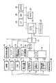
図1には本発明の実施形態のX線診断装置の主要部の機能ブロック図を示し、図2には当該X線診断装置の構造を示している。X線管5と、撮像システム6とがそれぞれCアーム4の両端に取り付けられている。X線管5は、高電圧発生器10から高電圧(管電圧)の印加を受けてX線を発生する。撮像システム6は、被検体Pを透過したX線を光学像に変換するイメージインテンシファイア(I.I.)29と、I.I.29から出力される光学像をTVカメラ8に誘導する光学系(図示しない)と、カメラコントローラ11の制御のもとで光学像を電気信号に変換するTVカメラ8とから構成される。
【0010】
撮影に際しては、X線管5と撮像システム6との間に、寝台7の天板(カテーテルテーブル)9上に載置された状態で被検体Pが配置される。寝台7は、天板9を前後方向(矢印B)及び左右方向(矢印E)に沿ってスライドし、また天板9を上下(矢印C)に沿って昇降するための天板スライド昇降機構部12を備えている。
【0011】
被検体Pに対する撮影方向を自由に変更することができるように、上記Cアーム4はアームホルダ1にスライド回転可能(矢印α)に保持され、またアームホルダ1はホルダベース3に回転可能(矢印β)に保持され、さらに撮像システム6はCアーム4に軸回転可能(矢印γ)に保持されている。矢印γの回転軸は、X線束中心軸(撮影中心線)に一致しており、この矢印γの回転軸に対して、矢印αの回転軸及び矢印βの回転軸が直交し、さらに矢印αの回転軸と矢印βの回転軸とも互いに直交し、かつこれら直交3軸の回転軸が一点(アイソセンタ)で交差するように設けられている。そのように直交3軸の回転軸をアイソセンタで交差するよう設けたことにより、Cアーム4を自由に回転させて、撮影方向を変更したとしても、画像中心点はアイソセンタに一致するものとなる。
【0012】
上記ホルダベース3は天井ベース28から吊り下げられており、この天井ベース28は天井に施設された直交する2系統のレール2,13に矢印A、Dに沿ってスライド可能に支持されている。これら矢印A、Dに関するスライド、および天板9の矢印B、C、Eに関するスライド及び昇降を自由に組み合わせることにより、被検体Pに対するアイソセンタの位置を自由に変更することが可能になっている。なお、Cアーム4を保持する構成1,2,3,13,28をCアーム保持装置14と称する。Cアーム保持装置14のこれら回転及びスライドはCアームスライド回転機構部15により駆動されるようになっている。
【0013】
上述した天板9の位置(B)及び高さ(C)はそれぞれロータリーエンコーダ等からなるセンサー16により検出され、またCアーム4の直交3軸の回転角度(α、β、γ)はそれぞれロータリーエンコーダ等からなるセンサー17により検出され、Cアーム4の位置(A,D)はそれぞれロータリーエンコーダ等からなるセンサー18により検出される。これらのセンサー出力はアナログマルチプレクサ19及びA/D変換機20を介してCPU21に供給され、CPU21ではこれらセンサー出力に基づいて位置及び角度の変更を制御するようになっている。
【0014】
また上述したTVカメラ8から出力される画像信号は画像発生部22に取り込まれ、NTSC等の規格に応じた2次元の投影画像データに変換され、そして図示しないディスプレイに可視画像として表示される。また、画像発生部22は多方向から撮影した投影画像データに基づいてマルチスライスの断層画像データを再構成したり、そのマルチスライスの断層画像データから特定部位を抽出しその部位の3次元(3D)データを生成する等の各種画像処理機能を備えている。
【0015】
CPU21には、3次元ワークステーション22が接続される。この3次元ワークステーション22には、上述した画像発生部22で発生する投影画像データや3Dデータ、X線CT24、MRI25、SPECT26等の3次元データ発生可能な他のモダリティからの3Dデータが直接的に又はPACS23を介して供給される。3次元ワークステーション22では、投影画像データや3Dデータを使って、入力デバイス27を介して入力される操作者の指示のもとでアイソセンタを被検体内部の病変部(注目点)に位置を合わせるために必要な処理機能を備えている。
【0016】
この3次元ワークステーション22の処理結果に従ってCPU21で矢印A,B,C,D,Eのスライドを任意に組み合わせてアイソセンタを被検体内部の病変部(注目点)に位置合わせすることにより、その後は、Cアーム4を矢印α、β、γに関してどのように回転させて撮影方向を変更したとしても、画像中心には常に病変部(注目点)が位置することになり、つまり撮影方向を変更するに際して、操作者は、矢印A,B,C,D,Eのスライドに関する操作を行う必要が無くなり、矢印α、β、γの回転に関する操作だけに専念することができ、これにより作業の迅速化、効率化、さらにはそれによる作業時間の短縮に伴って被曝線量の低減を図ることができるようになる。このアイソセンタを被検体内部の病変部(注目点)に位置合わせする処理について以下に詳細に説明する。
【0017】
事前の撮影により得られる当該被検体の病変部周辺領域に関する画像発生部22で発生される3Dデータ、またはX線CT等により事前に撮影された3Dデータが、3次元ワークステーション22に供給される。画像発生部22で発生される3Dデータを用いる場合には、不要であるが、X線CT等により事前に撮影された3Dデータを用いる場合には座標の整合処理が必要になる。つまり、X線CT等による3Dデータの座標系は、X線診断装置のアイソセンタを原点とする座標系とは、基本的に不一致であり、従って両座標系を整合(キャリブレーション)させる必要がある。
【0018】
このために、まず、図3に示すように、X線診断装置により2方向以上で撮影が実施される。この撮影により得られる撮影方向の異なる2つの投影画像は3次元ワークステーション22のディスプレイに表示される。操作者は入力デバイス27を介して、これら2つの投影画像上それぞれに対して例えば臨床学的上の特徴点を指定する。すると、3次元ワークステーション22では、それぞれの撮影位置及び方向、さらに2つの投影画像上それぞれの特徴点の2次元座標とに基づいて、当該特徴点のX線診断装置のアイソセンタを原点とする座標系上での座標(xx,yx,zx)を算出する。
【0019】
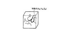
次に、3次元ワークステーション22のディスプレイに、3Dデータが表示され、この3D画像上で臨床学的に同じ特徴点が操作者により又は画像処理により自動的に指定される(図4)。この3Dデータ上の特徴点の座標(xW,yw,zw)は、3Dデータの座標系で表現されている。なお、3D画像上で特徴点を指定することには限定されず、3Dデータを2次元に投影し、その投影画像上で特徴点を指定してもよい。この際、2方向からの投影画像を生成し、それぞれの投影画像上で特徴点を指定するようにしてもよいし、1方向からだけの投影画像を生成し、その投影画像上で特徴点を指定して、この1点から奥行き方向(投影方向)に沿って3Dデータの値を追跡し、当該臨床学的な特徴点に対応する予め設定されたしきい値を超過した点の3D上の特徴点としてその3次元の座標を求めるようにしてもよい。
【0020】
3次元ワークステーション22は、臨床学的に同じ点に関する両座標(xx,yx,zx)、(xW,yw,zw)の間のズレベクトル(xx−xW,yx−yw,zx−zw)を求める。このズレベクトル(xx−xW,yx−yw,zx−zw)に基づいて3Dデータ上のある点(病変部等の注目点)の座標を、X線診断装置の座標に変換することができる。つまり、3Dデータ上のある点の座標から、ズレベクトルを引き算することで、当該点に関するX線診断装置の座標を求めることができる。
【0021】
次に、アイソセンタの位置決め作業である。まず、図5に示すように、3次元ワークステーション22のディスプレイに、3Dデータが表示され、この3D画像上の注目点(治療対象となる病変部)が、操作者により入力デバイス27を介して指定される。この場合も、特徴点の指定と同様に、3D画像上で注目点を指定することには限定されず、3Dデータを2次元に投影し、その投影画像上で注目点を指定してもよい。この際、2方向からの投影画像を生成し、それぞれの投影画像上で特徴点を指定するようにしてもよいし、1方向からだけの投影画像を生成し、その投影画像上で特徴点を指定して、この1点から奥行き方向(投影方向)に沿って3Dデータの値を追跡し、病変部に対応する予め設定されたしきい値を超過した点の3D上の注目点としてその3次元の座標を求めるようにしてもよい。
【0022】
そしてこの注目点の座標が、既に求めたズレベクトル(xx−xW,yx−yw,zx−zw)に基づいて、X線診断装置の座標に変換される。このX線診断装置の座標に変換された注目点に対する現在のアイソセンタの移動ベクトルが計算される(図6)。
【0023】
この移動ベクトルのデータは、3次元ワークステーション22からCPU21に供給され、CPU21はこの移動ベクトルに従って矢印A,B,C,D,Eのスライドを任意に組み合わせて移動することによりアイソセンタを被検体内部の病変部(注目点)に位置合わせすることができる。これにより矢印α、β、γに関して任意に回転させて撮影方向を任意に変更しても、常に病変部(注目点)が画像中心に位置することになり、撮影方向の変更作業が格段に効率化する。
【0024】
なお、施術者のためのカテーテル作業空間を確保する制約上等の理由で、C−アーム4の位置及び向きが既に固定されている場合、アイソセンタを被検体内部の病変部(注目点)に位置合わせするために、天板9の前後(B)、左右(E)、昇降(C)のスライドだけが行われることもある。
【0025】
また、この場合、被検体内部の病変部(注目点)を、アイソセンタを一致させる必要がなく、単に当該注目点を画像中心に位置させればよいこともあり、この場合には、X線管5からI.I.へのX線束中心軸上のいずれかの位置に、注目点が位置すればよい。この場合、移動が1軸減ることとなり、移動距離を短縮することができる。
【0026】
注目点をアイソセンタに一致させるか、また注目点がX線束中心軸上のいずれかの位置に合わせるか、いずれのモードを選択するかは、プリセットされ、又はその都度、操作者が選択する。
【0027】
また、注目点をアイソセンタに一致させ、または注目点をX線束中心軸上に合わせるためのスライドは、上述では、矢印A,B,C,D,Eのスライドを任意に組み合わせるとしたが、矢印B,C,Eの天板9に関するスライドだけで実現するようにしてもよいし、矢印A,DのCアーム4に関するスライドだけで実現するようにしてもよい。このスライドの選択についても、予めプリセットされていもよいし、その都度、操作者が選択するようにしてもよい。
【0028】
また、上述の説明では、注目点をアイソセンタに一致させ、又は注目点をX線束中心軸上に合わせるためにCPU21の制御により矢印A,B,C,D,Eのスライドを自動的に行うよう述べたが、このために必要な移動方向及び移動距離を例えばディスプレイ表示するようにしてもよい。操作者は表示された移動方向及び移動距離に従って、矢印A,B,C,D,Eのスライドを任意に組み合わせてマニュアルで操作することで、注目点をアイソセンタに一致させ、又は注目点をX線束中心軸上に合わせることができる。
【0029】
本発明は、上述した実施形態に限定されるものではなく、実施段階ではその要旨を逸脱しない範囲で種々変形して実施することが可能である。さらに、上記実施形態には種々の段階が含まれており、開示される複数の構成要件における適宜な組み合わせにより種々の発明が抽出され得る。例えば、実施形態に示される全構成要件から幾つかの構成要件が削除されてもよい。
【0030】
【発明の効果】
本発明によれば、位置決めに要する時間を短縮するとともに、被曝線量を低減することが実現され得る。
【図面の簡単な説明】
【図1】本発明の実施形態に係るX線診断装置の主要部構成を示すブロック図。
【図2】本実施形態に係るX線診断装置のガントリ部分の構造を示す図。
【図3】本実施形態において、2方向のX線投影画像上に指定された特徴点を示す図。
【図4】本実施形態において、3D画像上に指定された特徴点を示す図。
【図5】本実施形態において、3D画像上に指定された注目点(治療対象病変部)を示す図。
【図6】本実施形態において、注目点に対するアイソセンタの移動ベクトルを示す図。
【符号の説明】
1…アームホルダ、
2…天井レール、
3…ホルダベース、
4…Cアーム、
5…X線管、
6…撮像システム、
7…寝台、
8…TVカメラ、
9…天板(カテーテルテーブル)、
10…高電圧発生器、
11…カメラコントローラ、
12…天板スライド昇降機構部、
13…天井レール、
14…Cアーム保持装置、
15…Cアームスライド回転機構部、
16…天板位置高さ検出センサー、
17…角度検出センサー、
18…スライド位置検出センサー、
19…アナログマルチプレクサ、
20…A/D変換器、
21…CPU、
22…3次元ワークステーション、
23…PACS、
24…X線CT、
25…MRI、
26…SPECT、
27…入力デバイス、
28…天井ベース、
29…イメージインテンシファイア。[0001]
BACKGROUND OF THE INVENTION
The present invention relates to an X-ray diagnostic apparatus provided with a mechanism that can support an X-ray tube and an imaging system in a free posture so that the direction of imaging can be freely changed.
[0002]
[Prior art]
In X-ray diagnosis, particularly in angiography of a subject, for example, a C-arm type holding mechanism is used. An X-ray tube and an imaging system including an image intensifier, an optical system, and a TV camera are attached to the C arm. The C-arm is supported by the support mechanism so as to be rotatable about three orthogonal axes and slidable about two orthogonal axes. As a result, the subject can be imaged from any position and any direction.
[0003]
By the way, when the catheter is advanced to the lesion of the blood vessel under fluoroscopy of the angiographic image, it is better for the surgeon to understand the blood vessel that advances the catheter from other blood vessels around it. Can do. However, when the travel of the blood vessel (blood vessel structure) is complicated like a cerebral blood vessel, the blood vessel to be advanced by the catheter overlaps without being separated from other blood vessels, and the surgeon cannot better grasp the blood vessel. Things often happen.
[0004]
Therefore, in order to find an imaging direction in which there is little overlap of blood vessels and the blood vessel to be advanced through the catheter can be better grasped by the operator, angiographic imaging must be performed several times while changing the imaging position and imaging direction. However, this involves the problem of side effects associated with the injection of a large amount of contrast medium into the subject and the problem of a large amount of X-ray exposure, and thus cannot be practically performed. Therefore, the operator has to perform the procedure in a state where the blood vessel to be advanced by the catheter cannot be separated from other blood vessels.
[0005]
In this case, it is very difficult for the surgeon to advance the catheter to the lesion for the treatment purpose. Therefore, the examination time and the treatment time become long, and the burden on the patient and the surgeon is increased. In some cases, there is a risk that a blood vessel other than the blood vessel for treatment is treated.
[0006]
[Problems to be solved by the invention]
An object of the present invention is to reduce the time required for positioning and reduce the exposure dose in an X-ray diagnostic apparatus.
[0007]
[Means for Solving the Problems]
The present invention includes an X-ray tube, an imaging system that captures an X-ray image that is exposed from the X-ray tube and passes through a subject, an arm that holds the X-ray tube and the imaging system, and the arm Corresponding to a specified attention point in a three-dimensional image relating to the subject, a holding mechanism that supports the subject in a rotatable and movable manner, a bed that supports the subject between the X-ray tube and the imaging system, and And a controller that controls at least one of the holding mechanism and the bed so that the part is positioned at substantially the center of an image obtained by the imaging system.
[0008]
DETAILED DESCRIPTION OF THE INVENTION
In the following, a preferred embodiment of the device according to the present invention is described with reference to the drawings.
[0009]
FIG. 1 shows a functional block diagram of the main part of an X-ray diagnostic apparatus according to an embodiment of the present invention, and FIG. 2 shows the structure of the X-ray diagnostic apparatus. An X-ray tube 5 and an
[0010]
During imaging, the subject P is placed between the X-ray tube 5 and the
[0011]
The C arm 4 is slidably rotated by the arm holder 1 (arrow α) so that the imaging direction with respect to the subject P can be freely changed, and the
[0012]
The
[0013]
The position (B) and height (C) of the
[0014]
Further, the image signal output from the
[0015]
A three-
[0016]
In accordance with the processing result of the three-
[0017]
3D data generated by the
[0018]
For this purpose, first, as shown in FIG. 3, imaging is performed in two or more directions by the X-ray diagnostic apparatus. Two projection images obtained by this photographing and having different photographing directions are displayed on the display of the three-
[0019]
Next, 3D data is displayed on the display of the three-
[0020]
The three-
[0021]
Next, isocenter positioning work. First, as shown in FIG. 5, 3D data is displayed on the display of the three-
[0022]
And coordinates of the target point, already obtained displacement vector(x x -x W, y x -y w, z x -z w ), The coordinates of the X-ray diagnostic apparatus are converted. The movement vector of the current isocenter with respect to the point of interest converted into the coordinates of the X-ray diagnostic apparatus is calculated (FIG. 6).
[0023]
The data of the movement vector is supplied from the three-
[0024]
If the position and orientation of the C-arm 4 is already fixed for reasons such as restricting the catheter working space for the practitioner, the isocenter is positioned at the lesion (attention point) inside the subject. In order to match, only the front and rear (B), right and left (E), and elevating (C) sliding of the
[0025]
In this case, it is not necessary for the lesioned part (attention point) inside the subject to coincide with the isocenter, and the attention point may be simply positioned at the center of the image. In this case, the X-ray tube 5 to I.I. I. The point of interest may be positioned at any position on the X-ray bundle central axis. In this case, the movement is reduced by one axis, and the movement distance can be shortened.
[0026]
It is preset whether the point of interest coincides with the isocenter, the point of interest is aligned with any position on the X-ray bundle central axis, or which mode is selected, or the operator selects each time.
[0027]
Further, in the above description, the slide for making the attention point coincide with the isocenter or aligning the attention point on the X-ray bundle central axis is arbitrarily combined with the slides of the arrows A, B, C, D, and E. You may make it implement | achieve only by the slide regarding the
[0028]
Further, in the above description, the arrows A, B, C, D, and E are automatically slid under the control of the
[0029]
The present invention is not limited to the above-described embodiments, and various modifications can be made without departing from the scope of the invention at the stage of implementation. Furthermore, the above embodiment includes various stages, and various inventions can be extracted by appropriately combining a plurality of disclosed constituent elements. For example, some constituent requirements may be deleted from all the constituent requirements shown in the embodiment.
[0030]
【The invention's effect】
According to the present invention, it is possible to shorten the time required for positioning and reduce the exposure dose.
[Brief description of the drawings]
FIG. 1 is a block diagram showing a main part configuration of an X-ray diagnostic apparatus according to an embodiment of the present invention.
FIG. 2 is a diagram showing a structure of a gantry portion of the X-ray diagnostic apparatus according to the present embodiment.
FIG. 3 is a view showing feature points designated on an X-ray projection image in two directions in the present embodiment.
FIG. 4 is a view showing feature points designated on a 3D image in the present embodiment.
FIG. 5 is a view showing a point of interest (a lesion to be treated) designated on a 3D image in the present embodiment.
FIG. 6 is a diagram showing a movement vector of an isocenter with respect to a point of interest in the present embodiment.
[Explanation of symbols]
1 ... arm holder,
2 ... ceiling rail,
3 ... Holder base,
4 ... C-arm,
5 ... X-ray tube,
6 ... Imaging system,
7 ... Sleeper,
8 ... TV camera,
9 ... Top plate (catheter table),
10 ... High voltage generator,
11 ... camera controller,
12 ... Top plate slide lifting mechanism,
13 ... ceiling rail,
14 ... C-arm holding device,
15 ... C-arm slide rotation mechanism,
16 ... Top plate height detection sensor,
17 ... An angle detection sensor,
18 ... Slide position detection sensor,
19: Analog multiplexer,
20 ... A / D converter,
21 ... CPU,
22 ... 3D workstation,
23 ... PACS,
24 ... X-ray CT,
25 ... MRI,
26 ... SPECT,
27 ... Input device,
28 ... Ceiling base,
29 ... Image intensifier.
Claims (4)
Translated fromJapanese前記X線管から曝射され被検体を透過したX線の像を撮像する撮像システムと、
前記X線管と前記撮像システムとを支持するアームと、
前記アームを回転及び移動可能に保持する保持機構と、
前記被検体を前記X線管と前記撮像システムとの間に支持する寝台と、
前記被検体に関する3次元画像内の指定された注目点に対応する部位が前記撮像システムで得られる画像の略中心に位置するように、前記保持機構と前記寝台との少なくとも一方を制御する制御部とを具備することを特徴とするX線診断装置。An X-ray tube;
An imaging system that captures an X-ray image exposed from the X-ray tube and transmitted through the subject;
An arm that supports the X-ray tube and the imaging system;
A holding mechanism for holding the arm rotatably and movable;
A bed for supporting the subject between the X-ray tube and the imaging system;
A control unit that controls at least one of the holding mechanism and the bed so that a portion corresponding to a designated attention point in the three-dimensional image related to the subject is positioned at a substantially center of an image obtained by the imaging system. An X-ray diagnostic apparatus comprising:
前記X線管から曝射され被検体を透過したX線の像を撮像する撮像システムと、
前記X線管と前記撮像システムとを支持するアームと、
前記アームを直交3軸に関して回転可能に、且つ移動可能に保持する保持機構と、
前記被検体を前記X線管と前記撮像システムとの間に支持する寝台と、
前記被検体に関する3次元画像内の指定された注目点に対応する部位が前記直交3軸の交点に位置するように、前記保持機構と前記寝台との少なくとも一方を制御する制御部とを具備することを特徴とするX線診断装置。An X-ray tube;
An imaging system that captures an X-ray image exposed from the X-ray tube and transmitted through the subject;
An arm that supports the X-ray tube and the imaging system;
A holding mechanism for holding the arm so as to be rotatable and movable with respect to three orthogonal axes;
A bed for supporting the subject between the X-ray tube and the imaging system;
A control unit that controls at least one of the holding mechanism and the bed so that a portion corresponding to the designated attention point in the three-dimensional image related to the subject is located at the intersection of the three orthogonal axes; X-ray diagnostic apparatus characterized by the above.
Priority Applications (2)
| Application Number | Priority Date | Filing Date | Title |
|---|---|---|---|
| JP2000330534AJP4528426B2 (en) | 2000-10-30 | 2000-10-30 | X-ray diagnostic equipment |
| US09/984,530US6764217B2 (en) | 2000-10-30 | 2001-10-30 | X-ray diagnosis apparatus |
Applications Claiming Priority (1)
| Application Number | Priority Date | Filing Date | Title |
|---|---|---|---|
| JP2000330534AJP4528426B2 (en) | 2000-10-30 | 2000-10-30 | X-ray diagnostic equipment |
Publications (2)
| Publication Number | Publication Date |
|---|---|
| JP2002136507A JP2002136507A (en) | 2002-05-14 |
| JP4528426B2true JP4528426B2 (en) | 2010-08-18 |
Family
ID=18807037
Family Applications (1)
| Application Number | Title | Priority Date | Filing Date |
|---|---|---|---|
| JP2000330534AExpired - LifetimeJP4528426B2 (en) | 2000-10-30 | 2000-10-30 | X-ray diagnostic equipment |
Country Status (1)
| Country | Link |
|---|---|
| JP (1) | JP4528426B2 (en) |
Families Citing this family (23)
| Publication number | Priority date | Publication date | Assignee | Title |
|---|---|---|---|---|
| JP4331923B2 (en)* | 2002-07-29 | 2009-09-16 | 株式会社日立メディコ | 3D X-ray measurement device |
| US7505809B2 (en)* | 2003-01-13 | 2009-03-17 | Mediguide Ltd. | Method and system for registering a first image with a second image relative to the body of a patient |
| JP3971428B2 (en)* | 2005-03-03 | 2007-09-05 | 株式会社東芝 | X-ray diagnostic equipment |
| WO2006103580A1 (en)* | 2005-03-29 | 2006-10-05 | Koninklijke Philips Electronics N.V. | Method and apparatus for the observation of a catheter in a vessel system |
| US7603155B2 (en)* | 2005-05-24 | 2009-10-13 | General Electric Company | Method and system of acquiring images with a medical imaging device |
| JP2007205980A (en)* | 2006-02-03 | 2007-08-16 | Shimadzu Corp | Nuclear medicine diagnostic equipment |
| JP4961796B2 (en)* | 2006-03-30 | 2012-06-27 | 株式会社島津製作所 | Surgical X-ray diagnostic device |
| US8045677B2 (en)* | 2006-09-25 | 2011-10-25 | Koninklijke Philips Electronics N V Eindhoven | Shifting an object for complete trajectories in rotational X-ray imaging |
| US20080167545A1 (en)* | 2007-01-09 | 2008-07-10 | Oliver Meissner | Clinical workflow for combined 2D/3D diagnostic and therapeutic phlebograph examinations using a robotic angiography system |
| JP5085204B2 (en)* | 2007-07-03 | 2012-11-28 | 株式会社東芝 | Radioscopy apparatus and control method of radioscopy apparatus |
| JP5491700B2 (en)* | 2008-02-14 | 2014-05-14 | 株式会社東芝 | Data processing apparatus and X-ray apparatus |
| JP5729907B2 (en) | 2009-02-23 | 2015-06-03 | 株式会社東芝 | X-ray diagnostic equipment |
| JP5523722B2 (en)* | 2009-03-06 | 2014-06-18 | 株式会社東芝 | X-ray diagnostic imaging equipment |
| US20120235065A1 (en) | 2011-03-16 | 2012-09-20 | Intellirad Control, Inc. | Radiation control and minimization system and method |
| JP6199118B2 (en)* | 2012-09-10 | 2017-09-20 | 東芝メディカルシステムズ株式会社 | X-ray CT apparatus and medical image processing method |
| JP6222797B2 (en) | 2012-09-20 | 2017-11-01 | 東芝メディカルシステムズ株式会社 | X-ray diagnostic apparatus and program |
| JP6207819B2 (en) | 2012-09-20 | 2017-10-04 | 東芝メディカルシステムズ株式会社 | Image processing apparatus, X-ray diagnostic apparatus and program |
| JP6139170B2 (en)* | 2013-02-20 | 2017-05-31 | 東芝メディカルシステムズ株式会社 | X-ray imaging system and control device |
| CN104490411A (en)* | 2014-12-21 | 2015-04-08 | 李景英 | Imaging diagnosis device |
| EP3725228B1 (en)* | 2016-06-13 | 2023-07-19 | Shanghai United Imaging Healthcare Co., Ltd. | Systems and methods for x-ray scanner positioning |
| JP6608414B2 (en)* | 2017-11-13 | 2019-11-20 | キヤノンメディカルシステムズ株式会社 | X-ray diagnostic apparatus and angio CT apparatus |
| CN109192303B (en)* | 2018-08-26 | 2024-04-26 | 江苏中勤通信科技有限公司 | Medical image digital informatization comprehensive diagnosis instrument and use method thereof |
| KR102203618B1 (en)* | 2018-09-27 | 2021-01-15 | 오스템임플란트 주식회사 | Method and Apparatus for generating x-ray image, computer-readable recording medium |
Family Cites Families (5)
| Publication number | Priority date | Publication date | Assignee | Title |
|---|---|---|---|---|
| JPH01291831A (en)* | 1988-05-20 | 1989-11-24 | Mitsubishi Electric Corp | Positioning device |
| JP3725277B2 (en)* | 1996-02-15 | 2005-12-07 | 株式会社東芝 | X-ray diagnostic system and X-ray CT scanner |
| JPH119708A (en)* | 1997-06-25 | 1999-01-19 | Hitachi Medical Corp | Radiotherapy device |
| JP4330672B2 (en)* | 1998-06-05 | 2009-09-16 | 株式会社東芝 | X-ray diagnostic equipment |
| FR2781140B1 (en)* | 1998-07-17 | 2000-11-10 | Ge Medical Syst Sa | METHOD FOR POSITIONING A RADIOLOGY APPARATUS |
- 2000
- 2000-10-30JPJP2000330534Apatent/JP4528426B2/ennot_activeExpired - Lifetime
Also Published As
| Publication number | Publication date |
|---|---|
| JP2002136507A (en) | 2002-05-14 |
Similar Documents
| Publication | Publication Date | Title |
|---|---|---|
| JP4528426B2 (en) | X-ray diagnostic equipment | |
| US6496558B2 (en) | X-ray device and medical workplace for diagnostics and surgical interventions in the head and/or jaw of a patient | |
| CN101212931B (en) | X-ray diagnostic device | |
| EP2068713B1 (en) | Shifting an object for complete trajectories in rotational x-ray imaging | |
| JP6419462B2 (en) | X-ray diagnostic equipment | |
| US20020090058A1 (en) | X-ray diagnosis apparatus | |
| JP2008029844A (en) | X-ray hybrid diagnosis system | |
| JP2008029844A6 (en) | X-ray combined diagnosis system | |
| JPH11226002A (en) | Image forming system | |
| US20250114059A1 (en) | System for performing robotic surgery | |
| JP4313977B2 (en) | Laboratory specimen observation equipment | |
| EP3656305A1 (en) | Medical apparatus and method for operating the medical apparatus | |
| JP4744941B2 (en) | X-ray image diagnosis apparatus and diagnosis support method thereof | |
| JP3725277B2 (en) | X-ray diagnostic system and X-ray CT scanner | |
| JP2004073578A (en) | Medical image diagnostic apparatus and imaging support apparatus | |
| JP5656361B2 (en) | X-ray diagnostic equipment | |
| KR19990041733A (en) | X-ray apparatus and method capable of CT imaging | |
| JPH11347024A (en) | X-ray diagnostic equipment | |
| JP4575424B2 (en) | X-ray diagnostic equipment | |
| JP2009119281A (en) | Diagnostic equipment | |
| JP6116893B2 (en) | X-ray diagnostic imaging equipment | |
| JP4901646B2 (en) | X-ray diagnostic equipment | |
| JP4795527B2 (en) | X-ray diagnostic imaging system | |
| JP2002238884A (en) | Automatic condition setting mechanism of x-ray device | |
| JPH0654843A (en) | X-ray inspection device |
Legal Events
| Date | Code | Title | Description |
|---|---|---|---|
| A621 | Written request for application examination | Free format text:JAPANESE INTERMEDIATE CODE: A621 Effective date:20071004 | |
| A131 | Notification of reasons for refusal | Free format text:JAPANESE INTERMEDIATE CODE: A131 Effective date:20100330 | |
| A521 | Request for written amendment filed | Free format text:JAPANESE INTERMEDIATE CODE: A523 Effective date:20100416 | |
| TRDD | Decision of grant or rejection written | ||
| A01 | Written decision to grant a patent or to grant a registration (utility model) | Free format text:JAPANESE INTERMEDIATE CODE: A01 Effective date:20100511 | |
| A01 | Written decision to grant a patent or to grant a registration (utility model) | Free format text:JAPANESE INTERMEDIATE CODE: A01 | |
| A61 | First payment of annual fees (during grant procedure) | Free format text:JAPANESE INTERMEDIATE CODE: A61 Effective date:20100607 | |
| FPAY | Renewal fee payment (event date is renewal date of database) | Free format text:PAYMENT UNTIL: 20130611 Year of fee payment:3 | |
| R151 | Written notification of patent or utility model registration | Ref document number:4528426 Country of ref document:JP Free format text:JAPANESE INTERMEDIATE CODE: R151 | |
| FPAY | Renewal fee payment (event date is renewal date of database) | Free format text:PAYMENT UNTIL: 20130611 Year of fee payment:3 | |
| S111 | Request for change of ownership or part of ownership | Free format text:JAPANESE INTERMEDIATE CODE: R313114 Free format text:JAPANESE INTERMEDIATE CODE: R313117 Free format text:JAPANESE INTERMEDIATE CODE: R313111 | |
| R371 | Transfer withdrawn | Free format text:JAPANESE INTERMEDIATE CODE: R371 | |
| S111 | Request for change of ownership or part of ownership | Free format text:JAPANESE INTERMEDIATE CODE: R313117 Free format text:JAPANESE INTERMEDIATE CODE: R313111 Free format text:JAPANESE INTERMEDIATE CODE: R313114 | |
| R350 | Written notification of registration of transfer | Free format text:JAPANESE INTERMEDIATE CODE: R350 | |
| S533 | Written request for registration of change of name | Free format text:JAPANESE INTERMEDIATE CODE: R313533 | |
| R350 | Written notification of registration of transfer | Free format text:JAPANESE INTERMEDIATE CODE: R350 | |
| EXPY | Cancellation because of completion of term |