JP4528130B2 - Live finger detection by complex impedance four-point measurement - Google Patents
Live finger detection by complex impedance four-point measurementDownload PDFInfo
- Publication number
- JP4528130B2 JP4528130B2JP2004557000AJP2004557000AJP4528130B2JP 4528130 B2JP4528130 B2JP 4528130B2JP 2004557000 AJP2004557000 AJP 2004557000AJP 2004557000 AJP2004557000 AJP 2004557000AJP 4528130 B2JP4528130 B2JP 4528130B2
- Authority
- JP
- Japan
- Prior art keywords
- electrodes
- finger
- electrode
- impedance
- pickup
- Prior art date
- Legal status (The legal status is an assumption and is not a legal conclusion. Google has not performed a legal analysis and makes no representation as to the accuracy of the status listed.)
- Expired - Fee Related
Links
Images


Classifications
- A—HUMAN NECESSITIES
- A61—MEDICAL OR VETERINARY SCIENCE; HYGIENE
- A61B—DIAGNOSIS; SURGERY; IDENTIFICATION
- A61B5/00—Measuring for diagnostic purposes; Identification of persons
- A61B5/117—Identification of persons
- A—HUMAN NECESSITIES
- A61—MEDICAL OR VETERINARY SCIENCE; HYGIENE
- A61B—DIAGNOSIS; SURGERY; IDENTIFICATION
- A61B5/00—Measuring for diagnostic purposes; Identification of persons
- A61B5/05—Detecting, measuring or recording for diagnosis by means of electric currents or magnetic fields; Measuring using microwaves or radio waves
- A61B5/053—Measuring electrical impedance or conductance of a portion of the body
- A61B5/0531—Measuring skin impedance
- A—HUMAN NECESSITIES
- A61—MEDICAL OR VETERINARY SCIENCE; HYGIENE
- A61B—DIAGNOSIS; SURGERY; IDENTIFICATION
- A61B5/00—Measuring for diagnostic purposes; Identification of persons
- A61B5/68—Arrangements of detecting, measuring or recording means, e.g. sensors, in relation to patient
- A61B5/6801—Arrangements of detecting, measuring or recording means, e.g. sensors, in relation to patient specially adapted to be attached to or worn on the body surface
- A61B5/6813—Specially adapted to be attached to a specific body part
- A61B5/6825—Hand
- A61B5/6826—Finger
- A—HUMAN NECESSITIES
- A61—MEDICAL OR VETERINARY SCIENCE; HYGIENE
- A61B—DIAGNOSIS; SURGERY; IDENTIFICATION
- A61B5/00—Measuring for diagnostic purposes; Identification of persons
- A61B5/44—Detecting, measuring or recording for evaluating the integumentary system, e.g. skin, hair or nails
- A61B5/441—Skin evaluation, e.g. for skin disorder diagnosis
- A61B5/442—Evaluating skin mechanical properties, e.g. elasticity, hardness, texture, wrinkle assessment
- A—HUMAN NECESSITIES
- A61—MEDICAL OR VETERINARY SCIENCE; HYGIENE
- A61B—DIAGNOSIS; SURGERY; IDENTIFICATION
- A61B5/00—Measuring for diagnostic purposes; Identification of persons
- A61B5/68—Arrangements of detecting, measuring or recording means, e.g. sensors, in relation to patient
- A61B5/6801—Arrangements of detecting, measuring or recording means, e.g. sensors, in relation to patient specially adapted to be attached to or worn on the body surface
- A61B5/683—Means for maintaining contact with the body
- A61B5/6838—Clamps or clips
- G—PHYSICS
- G06—COMPUTING OR CALCULATING; COUNTING
- G06V—IMAGE OR VIDEO RECOGNITION OR UNDERSTANDING
- G06V40/00—Recognition of biometric, human-related or animal-related patterns in image or video data
- G06V40/10—Human or animal bodies, e.g. vehicle occupants or pedestrians; Body parts, e.g. hands
- G06V40/12—Fingerprints or palmprints
- G06V40/13—Sensors therefor
- G06V40/1306—Sensors therefor non-optical, e.g. ultrasonic or capacitive sensing
- G—PHYSICS
- G06—COMPUTING OR CALCULATING; COUNTING
- G06V—IMAGE OR VIDEO RECOGNITION OR UNDERSTANDING
- G06V40/00—Recognition of biometric, human-related or animal-related patterns in image or video data
- G06V40/40—Spoof detection, e.g. liveness detection
Landscapes
- Health & Medical Sciences (AREA)
- Life Sciences & Earth Sciences (AREA)
- Engineering & Computer Science (AREA)
- Physics & Mathematics (AREA)
- Molecular Biology (AREA)
- Surgery (AREA)
- Biophysics (AREA)
- Biomedical Technology (AREA)
- Heart & Thoracic Surgery (AREA)
- Medical Informatics (AREA)
- Veterinary Medicine (AREA)
- Pathology (AREA)
- Animal Behavior & Ethology (AREA)
- General Health & Medical Sciences (AREA)
- Public Health (AREA)
- Multimedia (AREA)
- Dermatology (AREA)
- Theoretical Computer Science (AREA)
- Human Computer Interaction (AREA)
- General Physics & Mathematics (AREA)
- Nuclear Medicine, Radiotherapy & Molecular Imaging (AREA)
- Radiology & Medical Imaging (AREA)
- Measurement Of The Respiration, Hearing Ability, Form, And Blood Characteristics Of Living Organisms (AREA)
- Measurement Of Length, Angles, Or The Like Using Electric Or Magnetic Means (AREA)
- Image Input (AREA)
- Measurement And Recording Of Electrical Phenomena And Electrical Characteristics Of The Living Body (AREA)
- Measurement Of Resistance Or Impedance (AREA)
- Professional, Industrial, Or Sporting Protective Garments (AREA)
- Gloves (AREA)
- Collating Specific Patterns (AREA)
- Measuring Pulse, Heart Rate, Blood Pressure Or Blood Flow (AREA)
- Investigating Or Analyzing Materials By The Use Of Electric Means (AREA)
Abstract
Description
Translated fromJapanese本発明は、構造の状態を決定するための、特に、構造の表面に近い特徴を測定することにより、測定された指紋が生きている指上にあるものか否かを確認するための、センサ・アセンブリ及び方法に関する。 The present invention relates to a sensor for determining the state of a structure, in particular for determining whether a measured fingerprint is on a living finger by measuring features close to the surface of the structure. -Relates to assemblies and methods.
導入部
容量またはインピーダンスをベースにした指紋センサは、生体計測による識別のための低価格で小型化された装置を提供する最も有望な方法の幾つかである。従って、このようなセンサは、移動電話等に一体化するための可能な候補である。Introduction Capacitance or impedance based fingerprint sensors are some of the most promising ways to provide low cost and miniaturized devices for biometric identification. Such sensors are therefore possible candidates for integration into mobile phones and the like.
指紋センサの信頼性を高めるために、偽造の指を用いることによりシステムをだますための幾つかの試みが検出されかつ排斥され得ることが非常に重要である。偽造の指は、代表的には指のものと類似した電気特性を有し、かつその表面に刻まれたまたはモールドされた指紋を有する厚板材料から成る。一層極端な場合においては、死んでいる切断された指を使用し得るということも想像され得る。 In order to increase the reliability of the fingerprint sensor, it is very important that some attempts to fool the system by using counterfeit fingers can be detected and rejected. A counterfeit finger typically consists of a plank material that has electrical properties similar to those of a finger and has a fingerprint engraved or molded on its surface. In more extreme cases, it can also be imagined that a dead severed finger can be used.
生きている指の検出システムにとっては、偽りの指を受け入れる確率(偽造受入れ比−FAR)及び本当の指を排斥する確率(偽り排斥比−FRR)の双方が極端に低いことが重要である。このことは、生きている指の非常に特徴的かつ独特の特性、すなわち、合成材料または生きている組織以外の生物学的物質のいずれによっても容易に複製されることができない特性、及び集団における大多数の指の典型である特性、を識別するための方法を開発することを重要にする。 For live finger detection systems, it is important that both the probability of accepting a fake finger (counterfeit acceptance ratio-FAR) and the probability of rejecting a real finger (fake rejection ratio-FRR) are extremely low. This is a very characteristic and unique property of living fingers, i.e. properties that cannot be easily replicated by either synthetic materials or biological materials other than living tissue, and in populations It is important to develop a method for identifying the characteristics that are typical of the majority of fingers.
低価格の容量性をベースにした指紋センサにとって、指の特性のインピーダンス測定の幾つかの種類が理想的である。その理由は、それが、最もしばしば、現存の測定構造を用いることにより、または幾つかの余分の電極を加えることにより、装置上に直接一体化され得るからである。 For a fingerprint sensor based on low cost capacitance, several types of finger characteristic impedance measurements are ideal. The reason is that it can most often be integrated directly on the device by using existing measurement structures or by adding some extra electrodes.
従来技術
US5,953,441に記載されているような二次元マトリクス・センサから、US6,289,114における半重複部分画像の列から指紋画像を再構成するセンサ・アレイを経て、EP0988614に記載されているような、指の表面を走査して指画像を再構成するよう測定された指速度を用いる線形センサまでの、幾つかの異なった種類の指紋センサが最近開発されてきている。Prior art described in EP 0898614 from a two-dimensional matrix sensor as described in US Pat. Several different types of fingerprint sensors have recently been developed, such as linear sensors that use finger velocities measured to reconstruct finger images by scanning the finger surface.
生きている指を検出する試みは、血液の酸化作用及び脈拍(血液のパルス)の双方の測定を含む。しかしながら、指内における血液の循環は、非常に冷えた指内では実質的に存在し得ないので、これらの方法は、水からの保護ができない。これらの原理は、また、低価格の装置で履行することが容易でもない。 Attempts to detect a living finger include measurements of both blood oxidation and pulse (blood pulses). However, these methods do not provide protection from water because blood circulation in the finger cannot be substantially present in very cold fingers. These principles are also not easy to implement with low cost devices.
US特許第6,175,641号、第5,953,441号及び米国出願US2001/0005424A1はすべて、指紋センサ上におかれた物体が生きている指に対応するか否かを調査する、異なったインピーダンスをベースにした方法を示している。 US Pat. Nos. 6,175,641, 5,953,441 and US application US2001 / 0005424A1 all investigate whether an object placed on a fingerprint sensor corresponds to a living finger. Shows a method based on impedance.
光マトリクス・センサ上のインピーダンス感知に関するUS特許第6,175,641号は、指の電気特性を測定するための2つの異なった方法を示している。第1に、センサ表面上の2つの接近して離間した電極コム(くし型)構造間にAC信号を印加することにより誘電定数が局部的に測定される。この測定方法は、商業的なプラスチック(低い誘電定数)から生きた組織(高い誘電定数)を分離し得るということが主張されている。 US Pat. No. 6,175,641 relating to impedance sensing on an optical matrix sensor shows two different methods for measuring the electrical properties of a finger. First, the dielectric constant is measured locally by applying an AC signal between two closely spaced electrode comb structures on the sensor surface. It is claimed that this measurement method can separate living tissue (high dielectric constant) from commercial plastic (low dielectric constant).
第2に、該センサは、指のインピーダンスを決定するために、いわゆる二重ドット電極を有しており、それは、おそらく、偽造の指から本当の指を識別するために用いられ得る追加の情報を与えるであろう。該特許は、また、測定の安全性を増すために、幾つかの周波数を使用することをも述べている。 Secondly, the sensor has a so-called double dot electrode to determine the finger impedance, which is probably additional information that can be used to distinguish a real finger from a counterfeit finger. Would give. The patent also mentions the use of several frequencies to increase the safety of the measurement.
しかしながら、この特許に記載された方法は、幾つかの弱点を有している。誘電測定は、おそらく、乾いた指に対しては良く働くけれども、汗または湿った指に対しては、接近して離間されたコム(くし型)構造は、塩類の汗によってほとんど恐らく短絡してしまい、有用な情報が得られないであろう。 However, the method described in this patent has several weaknesses. Dielectric measurements probably work well for dry fingers, but for sweat or wet fingers, the closely spaced comb structure is almost probably shorted by salt sweat. Therefore, useful information will not be obtained.
さらに、二重ドット・システムによって測定される生きた指のインピーダンスは、指の湿度に依存して大きさの少なくとも一次数でもって変わり得る。従って、指を識別するためにこれを規準として用いることは困難であり、双方のインイーダンスの大きさ、周波数とのその位相及びその変動は、剥かれたポテトのような毎日の生活から単に良く知られている材料によっておそらく偽造され得る。 Furthermore, the impedance of a living finger as measured by a double dot system can vary with at least a first order of magnitude depending on the humidity of the finger. Therefore, it is difficult to use this as a criterion to identify a finger, the magnitude of both in-Eance, its phase with frequency and its variation is simply from daily life like stripped potatoes. It can possibly be counterfeited by well-known materials.
特許第5,953,441号は、容量性感知素子のマトリクスを含むAC容量性指紋センサのためのいんちきな検出を記載している。ここでは、生きた指の検出に対する主なアイデアは、センサ領域の縁の周りに電極を通してAC信号を送り、センサ素子上の信号の位相を検出することであり、この位相は、生きた指の特性である。 Japanese Patent No. 5,953,441 describes tedious detection for an AC capacitive fingerprint sensor that includes a matrix of capacitive sensing elements. Here, the main idea for live finger detection is to send an AC signal through the electrodes around the edge of the sensor area and detect the phase of the signal on the sensor element, which phase is It is a characteristic.
しかしながら、この方法は、幾つかの異なった偽造の指の材料を許さないけれども、指とほぼ同じ位相を与える材料を見つけて、それによりシステムをだますことは比較的容易であろう。 However, although this method does not allow several different counterfeit finger materials, it would be relatively easy to find a material that gives nearly the same phase as the finger and thereby fool the system.
特許出願US2001/0005424A1は、6,175,641号に記載された方法と似た方法を示している。指のインイーダンス(2つの電極の間、または1つの電極と“無限遠”との間のいずれかの)は、周波数の関数として測定される。曲線を基準曲線と比較することにより、指の生きた特性が、次に、検出され得る。しかしながら、この方法は、上述した方法とほとんど何も変らない。異なった指間の、及び同じ指の異なった状態(例えば、湿度に対して)間の絶対インピーダンス及び周波数応答は、非常に異なるので、“生きている指の判定規準”は、非常に広いに違いないであろうし、それ故、その原理は、だますのが容易であろう。 Patent application US2001 / 0005424A1 shows a method similar to that described in US Pat. No. 6,175,641. Finger inefficiency (either between two electrodes or between one electrode and “infinity”) is measured as a function of frequency. By comparing the curve to a reference curve, the live characteristics of the finger can then be detected. However, this method is almost the same as the method described above. Since the absolute impedance and frequency response between different fingers and between different states of the same finger (eg against humidity) are very different, the “living finger criterion” is very broad. It must be, and therefore the principle will be easy to trick.
参照によりここに含まれる国際特許出願PCT/NO03/00157(WO03094724)は、複素インピーダンスの4点測定に基づくもう1つの生きている指の検出原理を示している。ここで、AC電流または電圧が2つの電極間に印加され、その間、他の2つの電極間の電圧降下が測定され、すべての電極は、指の表面と接触している。指のインピーダンス測定に与えられる4点原理は、図1に可視化されている。AC電流が外部電極を通して指に送られ、その間、差動増幅器を用いて2つの内部電極間で電圧降下が測定される。 International patent application PCT / NO03 / 00157 (WO03094724), incorporated herein by reference, shows another living finger detection principle based on a four-point measurement of complex impedance. Here, an AC current or voltage is applied between the two electrodes while the voltage drop between the other two electrodes is measured and all electrodes are in contact with the finger surface. The four-point principle given to finger impedance measurement is visualized in FIG. An AC current is sent to the finger through the external electrode, while the voltage drop is measured between the two internal electrodes using a differential amplifier.
本発明の目的は、変化する角質層の厚さのような集団の中での指の特性における差を補償するために用いられ得る、生きている指の検出のための4点測定システムを確実にすることである。 It is an object of the present invention to ensure a four-point measurement system for live finger detection that can be used to compensate for differences in finger characteristics within the population, such as varying stratum corneum thickness. Is to do.
この目的を達成するために、提案された本発明は、少なくとも4つの電極のアレイを有するインピーダンス測定システムから成る。電極は、指と直接接触していても良く、または絶縁層を介して指に容量的に結合されても良い。電極は、電流及び電圧感知電極間の異なった相対配置に対応する、少なくとも2つの異なった4点電極構成で用いられ得るように配列される。本発明の目的は、特許請求の範囲に記載されるように得られる。 To achieve this object, the proposed invention consists of an impedance measurement system having an array of at least four electrodes. The electrode may be in direct contact with the finger or may be capacitively coupled to the finger via an insulating layer. The electrodes are arranged so that they can be used in at least two different four-point electrode configurations, corresponding to different relative arrangements between the current and voltage sensing electrodes. The object of the invention is obtained as described in the claims.
4点技術の使用は、ホーニー層もしくは角質層の直列インピーダンスを相殺し、従って、指の内部のインピーダンスを直接測定することを可能とする。角質層のインピーダンスは、皮膚の湿度に及び温度のような周囲条件に極端に依存する。このことは、偽造の指から本当の指を分離するために用いられ得る“狭い”判定規準を識別することを困難にする。対照的に、指の内部の湿度は、変化する周囲条件の下で殆ど一定のままである。従って、指の内部(生きている皮膚及び組織)のインピーダンスは、さらに一定であり、人から人に一層再現可能である。 The use of the four-point technique cancels the horny or stratum corneum series impedance, thus allowing the impedance inside the finger to be measured directly. The stratum corneum impedance is extremely dependent on skin humidity and ambient conditions such as temperature. This makes it difficult to identify “narrow” criteria that can be used to separate a real finger from a counterfeit finger. In contrast, the humidity inside the finger remains almost constant under changing ambient conditions. Therefore, the impedance inside the finger (live skin and tissue) is more constant and more reproducible from person to person.
従って、4点原理は、指が本当の生きている指であるか否かを識別するために用いられ得る“狭い”判定規準を得ることを一層容易にするであろう。 Thus, the four-point principle will make it easier to obtain a “narrow” criterion that can be used to identify whether a finger is a real living finger or not.
皮膚の層を成された構造のために、4点原理は、また、固有の“深さの選択性”をも与える。周波数を高めることにより、測定値は、生きている皮膚のさらに一層深い部分によって影響を受ける。このことは、単に周波数掃引を行なうことによって電気特性における深さ特有の変動を測定することを可能とする。 Because of the layered structure of the skin, the four-point principle also provides an inherent “depth selectivity”. By increasing the frequency, measurements are affected by even deeper parts of live skin. This makes it possible to measure depth-specific variations in electrical properties by simply performing a frequency sweep.
指の内部の生きている組織は、また、高い安全性の程度を有して本当の指を識別するために用いられ得る大変な特性的分散度(周波数に対する電気特性の変化)をも有している。これらの特性は、死後または指が手から切断されたときに変化し、指が生きているか否かを決定することをも可能とする。 The living tissue inside the finger also has a great characteristic dispersion (change in electrical characteristics with respect to frequency) that can be used to identify a real finger with a high degree of safety. ing. These characteristics change after death or when the finger is disconnected from the hand, making it possible to determine whether the finger is alive.
PCT/NO03/00157(WO03094724)で提案された原理の1つの弱点は、4点インピーダンスが、一定の距離をすべての電極が有する場合の一組の電極だけでインピーダンスが測定されるというようなものであるということである。 One weakness of the principle proposed in PCT / NO03 / 00157 (WO03094724) is that the impedance is measured with only one set of electrodes when all electrodes have a fixed distance, with a four-point impedance. It is that.
しかしながら、4点構造の電極の相対位置に依存して、インピーダンス測定は、多かれ少なかれ、角質層(角層またはホーニー層)によって影響を受けるであろう。 However, depending on the relative position of the four point electrode, the impedance measurement will be more or less influenced by the stratum corneum (horny layer or horny layer).
電流電極間の非常に短い距離の制限において、電流は、指の内部の生きている皮膚内に入り込まず、従って、角質層だけの測定が与えられるであろう。 In limiting the very short distance between the current electrodes, the current will not penetrate into the living skin inside the finger and therefore only a stratum corneum measurement will be given.
他の制限において、大きい電極距離の場合、測定は、指の内部の生きている組織の特性によって大いに決定されるであろう。 In other limitations, for large electrode distances, the measurement will be largely determined by the characteristics of the living tissue inside the finger.
異なった人は、異なった角質層の厚さを有するので、一定の電極距離は、異なった人に対して異なった結果を与え、従って、非常に広い判定規準を用いずに、生きている指を識別することを困難にするであろう。判定規準が充分に狭くなければ、原理は、だますのが一層容易であろう。 Since different people have different stratum corneum thickness, a constant electrode distance gives different results for different people, and thus without using very broad criteria, living fingers Would make it difficult to identify. If the criteria are not narrow enough, the principle will be easier to trick.
電極が異なった相対配置を有する異なった電極構成は、電極に隣接する対象物の異なった部分の測定に対応するということが熟練したエンジニアには知られているであろう。しかしながら、4点原理によって測定される指の部分は、2つの電流感知電極間距離及び2つの電圧感知電極間距離によって決定されるだけでなく、電極の幾何学的配列及び電流電極に対する電圧感知電極の相対的配列に基づいても決定される。 It will be known to the skilled engineer that different electrode configurations with different relative arrangements of electrodes correspond to the measurement of different parts of the object adjacent to the electrodes. However, the finger portion measured by the four-point principle is not only determined by the distance between the two current sensing electrodes and the distance between the two voltage sensing electrodes, but also the electrode geometry and the voltage sensing electrodes relative to the current electrodes. It is also determined based on the relative sequence of
従って、アレイ内の異なった電極を付勢することによって、または既に使用中の電極の役割(電圧感知または電流)を交換することによって、それは、異なった4点電極構成間で切換えられ得る。 Thus, it can be switched between different four-point electrode configurations by energizing a different electrode in the array or by exchanging the role of the electrode already in use (voltage sensing or current).
アレイ内の幾つかの異なった電極構成間で切換えることによって、例えば異なった測定深さに対応する指の部分を測定することがこのように可能となり、従って、例えば角質層の厚さにおける変化を補償することが可能となる。 By switching between several different electrode configurations in the array, it is thus possible, for example, to measure the part of the finger corresponding to different measurement depths, and thus to change the thickness of the stratum corneum, for example. It becomes possible to compensate.
例示するために、1つの電極配列を用いて一人の人に対して観察される特性分散度(周波数に対する複素インピーダンスのシフト)が、もう1つの配列を用いてもう一人の人のために検出され得る。 To illustrate, the characteristic dispersion (shift of complex impedance with respect to frequency) observed for one person using one electrode array is detected for another person using another array. obtain.
同じ分散度を示すために、例えば、非常に厚い角質層を有する人は、薄い角質層を有する人よりも、電流注入または電圧感知電極間の距離が大きいことが必要であり得る。 To show the same degree of dispersion, for example, a person with a very thick stratum corneum may need a greater distance between current injection or voltage sensing electrodes than a person with a thin stratum corneum.
対象物を生きている指として受け入れるための最小の判定規準は、電極配列の少なくとも1つに対して、少なくとも1つの特定のインピーダンス関連の現象が検出されるということであり得る。 The minimum criterion for accepting an object as a living finger may be that at least one particular impedance related phenomenon is detected for at least one of the electrode arrays.
“角質層の厚さにおける差”への関心は、単に例示であるということを強調しておく。本原理は、電極の幾何学的配列におけるシフトが、与えられた周波数範囲内のインピーダンス関連の或る現象を示すのを助け得るすべての指の特性に適用される。 It is emphasized that the interest in “difference in stratum corneum thickness” is merely exemplary. This principle applies to all finger characteristics where a shift in the electrode geometry can help to show certain impedance related phenomena within a given frequency range.
好ましくは、相当数の大人数に渡って生きている指を検出することの保証を高めるために、可能な電極構成の数は、2よりも大きく、例えば3−5であり得る。もちろん、最小の切換えが必要とされるように別のアレイの形態で種々の構成が配置され得る。 Preferably, the number of possible electrode configurations may be greater than 2, for example 3-5, in order to increase the assurance of detecting living fingers over a considerable number of adults. Of course, the various configurations can be arranged in different arrays such that minimal switching is required.
以下、例としてのみ本発明を示す添付図面を参照して本発明を説明する。 The invention will now be described with reference to the accompanying drawings which illustrate the invention by way of example only.
実際の履行
図1において、指の表面11は、幾つかのセンサ10上に位置付けられる。指の構造は、2つの層、すなわち、生きている指の角質層12及び生きている組織13を含む。角質層(ホーニー層もしくは角層)12は、4つの示された電極10の各々において、それぞれ、インピーダンスZ1、Z2、Z3及びZ4を構成し、生きている組織は、インピーダンスZ0を表す。Actual Implementation In FIG. 1, a finger surface 11 is positioned on
実際の装置において、4点測定は、例えば、薄膜、厚膜または印刷回路基板技術において区画されるセンサ表面上の電極のアレイによって履行され得る。電極は、指との直流電気による接触を与え得るか、または電極から指への純粋な容量性結合を与えるように薄い誘電体で不導態化され得るかのいずれかである。 In an actual device, the four-point measurement can be implemented by an array of electrodes on the sensor surface, for example partitioned in thin film, thick film or printed circuit board technology. The electrode can either provide direct galvanic contact with the finger, or can be passivated with a thin dielectric to provide pure capacitive coupling from the electrode to the finger.
個々の電極(電流電極及び電圧電極の双方)の代表的な寸法は、0.5−5mm2であり、そして代表的な最小電極間隔は、0.3−2mmである。The typical dimensions of the individual electrodes (both current and voltage electrodes) are 0.5-5 mm2 and the typical minimum electrode spacing is 0.3-2 mm.
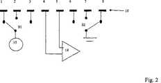
図2は、幾つかの異なった電流電極距離における測定を可能とするために8つの電極のアレイが如何に配列され得るかの例を示す。この構造において電圧測定は、常に、電極4及び5間で行われ、2つのスイッチS1及びS2は、電極1、2、3(AC源)と電極6、7及び8(ACドレインもしくは接地)との異なった組み合わせを為すように用いられ、それにより、電流電極距離を変化させる。代替的には、電流及び電圧感知電極の役割は、交換されることができ、それにより、電流は、常に最奥の電極間に送られ、電圧測定は、残りの電極の種々の組み合わせの間で切換えられる。電圧感知の対の役割が電流電極対と交換されるならば、測定されるインピーダンスは、本質的に同じままであるということが従来技術から知られている。 FIG. 2 shows an example of how an array of 8 electrodes can be arranged to allow measurements at several different current electrode distances. In this structure, voltage measurement is always performed between
集団における角質層の厚さ変化(または湿度における差のような対応の影響を与える他の変化)に対応する電極間距離の範囲を選択することによって、一層直接的に比較され得る情報、従って、本当の指に対する規準を“狭める”ように用いられ得る情報を得ることが可能である。このことは、上述した方法の幾つかよりも高い確かさの程度で生きている指識別を可能とする。 Information that can be compared more directly by selecting a range of interelectrode distances corresponding to stratum corneum thickness changes in the population (or other changes that affect the correspondence, such as differences in humidity), thus It is possible to obtain information that can be used to “narrow” the criteria for a real finger. This allows live finger identification with a higher degree of certainty than some of the methods described above.
読み出しシステムを設計する際、電圧感知分岐における入力インピーダンスを最大にすることが重要であり、その理由は、低すぎるインイーダンスは、測定原理に影響を与える寄生入力電流を生じるからである。入力インピーダンスの影響を最小にするために、US4,956,729に記載されたような増幅結合が用いられ得る。電圧パッドに対する入力電流も、入力パッドそれ自体(“能動遮蔽もしくはシールド”)と同じ電圧を有する電極により入力パッド(及びそれを増幅器に接続するトラック)を遮蔽することにより最小にされ得る。このような電圧は、入力電圧が遮蔽電極にフィードバックされる単純な電圧フォロア段によって得られる。 When designing a readout system, it is important to maximize the input impedance in the voltage sensing branch because too low an impedance causes a parasitic input current that affects the measurement principle. In order to minimize the effect of input impedance, amplification coupling as described in US 4,956,729 can be used. The input current to the voltage pad can also be minimized by shielding the input pad (and the track connecting it to the amplifier) with an electrode having the same voltage as the input pad itself (“active shielding or shielding”). Such a voltage is obtained by a simple voltage follower stage in which the input voltage is fed back to the shield electrode.
増幅器の入力インピーダンスが充分に高いならば(もしくは等価的に、入力電流が充分に低いならば)、検出された電圧は、ホニー層もしくは角質層を通るインイーダンスZ2、Z3、Z1及びZ4によって影響されないが、指の内部の特性であるZ0によってのみ影響される。 If the input impedance of the amplifier is high enough (or equivalently, if the input current is low enough), the detected voltage is caused by the impedances Z2, Z3, Z1 and Z4 through the honey layer or stratum corneum. Not affected, but only affected by Z0, a characteristic inside the finger.
指における開示されたシステムは、電極が配列され得るただ1つの可能な方法であるということが強調されるべきである。原理的には、2つまたは3つ以上の異なった電極構成をもたらすすべての電極配列が用いられ得る。電圧またはインピーダンス感知に対して、指紋センサ素子それ自体が用いられ得る。 It should be emphasized that the disclosed system on the finger is the only possible way the electrodes can be arranged. In principle, all electrode arrangements that result in two or more different electrode configurations can be used. For voltage or impedance sensing, the fingerprint sensor element itself can be used.
生きている指の検出時に、4点複素インピーダンス測定が、単一周波数に対して、もしくは周波数の範囲を横切って電極配列の各々ごとに得られる。例えば、特性は、周波数で連続的に、もしくは幾つかの異なった離散的な周波数において測定されることができる。周波数スパンは、好ましくは、1−3程度の大きさである。 Upon detection of a live finger, a four point complex impedance measurement is obtained for each of the electrode arrays for a single frequency or across a range of frequencies. For example, the characteristics can be measured continuously in frequency or at several different discrete frequencies. The frequency span is preferably about 1-3.
単一のサイクル中の少なくとも2つの異なった時間的瞬間における差電圧及び指を通る電流の振幅を測定することにより、複素インピーダンスZ0=R0+jX0のリアクタンスX0及び抵抗R0が、各周波数ごとに決定され得る。複素インピーダンスの成分を検出するための他の技術も用いられ得る。 By measuring the differential voltage and the amplitude of the current through the finger at at least two different time instants during a single cycle, the reactance X0 and resistance R0 of the complex impedance Z0 = R0 + jX0 can be determined for each frequency. . Other techniques for detecting components of complex impedance can also be used.
生きている指のデータは、指紋画像の取得のすぐ前に、またはすぐ後に、もしくは取得している間に記録されるのが好ましい。このことは、最初に本当の指を適用し、次に、正しい指紋パターンを有する偽造の指を適用することにより、システムをだますのを困難にする。幾つかのシステムにおいては、生きている指の検出及び指紋画像化は、競合する信号に起因して同時には行われないかもしれない。この場合においては、短時間間隔の間、指紋の画像化を中断して、この時間フレーム内で、生きている指の検出を行うことが可能である。次に、生きている指の検出のための時間は、画像品質に相当の影響を与えるのを回避するために充分に短いということが重要である。 Live finger data is preferably recorded immediately before, after, or during the acquisition of the fingerprint image. This makes it difficult to fool the system by first applying a real finger and then applying a counterfeit finger with the correct fingerprint pattern. In some systems, live finger detection and fingerprint imaging may not occur simultaneously due to competing signals. In this case, it is possible to interrupt fingerprint imaging for a short time interval and to detect a live finger within this time frame. Secondly, it is important that the time for detection of a live finger is short enough to avoid significant impact on image quality.
EP0988614に記載された型の掃引センサに対しては、これは、例えば、画像データの1または2ラインをスキップすることにより達成されることができ、そしてこの時間中に生きている指の検出を行う。上述したように、この解決法は、模擬電極とセンサ素子との間のインピーダンスを測定するための幾つかのセンサ素子を含む。本発明によれば、センサ素子の役割は、指の状態を測定するための1つまたは2、3の測定周期の間変更され得る。上述の出願に記載された解決法は、不必要なデータの過剰サンプリング及び排斥を許容するので、生きている指の検出モードは、結果の指紋画像において注目すべきものではない。 For a sweep sensor of the type described in EP 0898614, this can be achieved, for example, by skipping one or two lines of image data, and detection of a live finger during this time. Do. As described above, this solution includes several sensor elements for measuring the impedance between the simulated electrode and the sensor element. According to the invention, the role of the sensor element can be changed during one or a few measurement periods for measuring the state of the finger. The solution described in the above application allows over-sampling and rejection of unnecessary data, so the live finger detection mode is not noticeable in the resulting fingerprint image.
この場合において、生きている指の検出のために用いられる幾何学的領域が、指紋画像化のために用いられる領域と重複するということも重要であり、それにより、検出された生きている指と画像化された物体とが実際同じであるということを確かめることができる。 In this case, it is also important that the geometric region used for detection of the live finger overlaps with the region used for fingerprint imaging, so that the detected live finger And that the imaged object is actually the same.
前述したように、物体を生きている指として受け入れるための判定規準は、電極構成の少なくとも1つからの少なくとも1つのインピーダンス関連パラメータの測定に基づかれ得る。 As described above, the criteria for accepting an object as a living finger may be based on the measurement of at least one impedance related parameter from at least one of the electrode configurations.
このパラメータは、例えば、位相、大きさ、抵抗またはリアクタンスのような測定されたインピーダンスに関連する値またはそれらの値の組み合わせであって良く、もしくは周波数に関する幾つかの値の変化であっても良い。パラメータは、また、幾つかの導出された値であっても良く、例えば、幾つかのパラメータが或る値に達する周波数であって良い。 This parameter can be, for example, a value related to the measured impedance, such as phase, magnitude, resistance or reactance, or a combination of those values, or it can be a change of some value with respect to frequency. . The parameter may also be some derived value, for example the frequency at which some parameter reaches a certain value.
好適な実施形態において、これらのパラメータの少なくとも1つは、約10kHz及び1MHz間の周波数範囲内で生じる測定された4点指インピーダンスの観察された位相変化に関係している。この周波数範囲において、指インピーダンスの位相は、インピーダンスの支配部分が容量性から抵抗性に変化するよう、50−90度のシフトを受けることが分かってきた。 In a preferred embodiment, at least one of these parameters is related to the observed phase change of the measured four-point finger impedance occurring within a frequency range between about 10 kHz and 1 MHz. In this frequency range, it has been found that the phase of the finger impedance undergoes a 50-90 degree shift so that the dominant part of the impedance changes from capacitive to resistive.
支配的な容量性から抵抗性インピーダンスへの変化は、また、周波数が典型的な周波数を通過するときに負からゼロ近辺に変化する、インピーダンスの大きさの周波数微分における変化としても見られる。 The change from dominant capacitive to resistive impedance is also seen as a change in the frequency derivative of the magnitude of the impedance, which changes from negative to near zero as the frequency passes through a typical frequency.
図4−7は、2つの異なった電極構成に対し、異なった人からの幾つかの生きている指のためのインピーダンスの測定された位相及び大きさを示す。図4及び5は、一方の電極構成に言及しており、図6及び7は、もう一方の電極構成に言及している。 FIGS. 4-7 show the measured phase and magnitude of impedance for several living fingers from different persons for two different electrode configurations. 4 and 5 refer to one electrode configuration and FIGS. 6 and 7 refer to the other electrode configuration.
位相における強い正のシフトは、双方の構成に対して観察される。インピーダンス曲線は、位相遷移の周波数より上で実質的に平らであるということも観察される。 A strong positive shift in phase is observed for both configurations. It is also observed that the impedance curve is substantially flat above the frequency of the phase transition.
同様の現象は、我々が検査した任意の他の物質に対しては観察されない。そのように強い位相シフトは、指が単に2点インピーダンス測定を用いて測定される場合には、観察されない。従って、これは、指の正当性を決定するための可能な判定規準である。 Similar phenomena are not observed for any other material we have examined. Such a strong phase shift is not observed if the finger is simply measured using a two-point impedance measurement. This is therefore a possible criterion for determining the legitimacy of a finger.
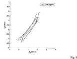
その大きさ及びその遷移周波数のようなこの周波数シフトの特性は、幾つかの異なった方法で特徴付けることができる。例えば、測定された複素インピーダンスは、周波数に対して位相及び大きさをプロットすることにより、または図8に示すようにパラメータとしての周波数で実数部に対して虚数部をプロットすることにより、周波数の関数としてプロットされることができる。この図において、測定されたインピーダンスZI及びZRの虚数部及び実数部を示して、生きている指を識別するための可能な分析が示されている。勾配の上に述べられているように、これらの曲線の長さまたは重心は、生きている指を識別するための幾つかの可能なパラメータである。好適な実施形態においては、勾配は、生きている指の確認のためのベースとして用いられる。The characteristics of this frequency shift, such as its magnitude and its transition frequency, can be characterized in several different ways. For example, the measured complex impedance can be obtained by plotting the phase and magnitude against frequency or by plotting the imaginary part against the real part with frequency as a parameter as shown in FIG. Can be plotted as a function. In this figure, the imaginary and real parts of the measured impedances ZI and ZR are shown, and a possible analysis for identifying a living finger is shown. As stated above the gradient, the length or centroid of these curves are several possible parameters for identifying a living finger. In a preferred embodiment, the gradient is used as a basis for live finger identification.
後者の方法の利点は、たとえ遷移点が全く異なった周波数に対して生じる場合でさえ、異なった指に対して曲線が同様に見えるということである。 The advantage of the latter method is that the curve looks the same for different fingers, even if the transition points occur for completely different frequencies.
曲線の微分、長さ、“質量の中心”、特定の遷移周波数、もしくは曲線が或る値に接近するときの周波数のようなこれらの曲線の或る特性は、次に、自動計算ユニットによって導出され得、そして生きている指の識別パラメータとして用いられ得る。熟練したエンジニアは、その多くが数学的に等価である幾つかの異なった方法で同じ測定された特性が提起され得ることに精通しているであろう。 Certain characteristics of these curves, such as the derivative of the curve, length, "center of mass", specific transition frequency, or frequency when the curve approaches a certain value, are then derived by the automatic calculation unit. And can be used as a live finger identification parameter. Skilled engineers will be familiar with the same measured properties that can be presented in several different ways, many of which are mathematically equivalent.
電極間の距離が増加するときに、代表的なシフト周波数が変化するということも観察されてきた。これは、概して大きい距離が指における一層高い測定深さを与えるからであり、そして指の電気的特性が深さと共に変るということである。これは、短い電極距離に対応する図4及び5における曲線を、図6及び7(より長い電極距離)の曲線と比較することによって視覚化される。図4及び5において、代表的な遷移周波数は、図6及び7におけるよりも大いに低い。 It has also been observed that the typical shift frequency changes as the distance between the electrodes increases. This is because generally large distances give a higher measurement depth at the finger, and the electrical properties of the finger vary with depth. This is visualized by comparing the curves in FIGS. 4 and 5 corresponding to short electrode distances with the curves in FIGS. 6 and 7 (longer electrode distance). In FIGS. 4 and 5, the typical transition frequency is much lower than in FIGS.
生きている指に対して重要な特性である、電極距離に対する遷移周波数における測定されたシフトは、パラメータ的に表されることができ、そして、これまたはこれらのパラメータは、生きている指の識別モデルを改善するために用いられ得る。 The measured shift in transition frequency relative to electrode distance, which is an important characteristic for live fingers, can be expressed parametrically, and this or these parameters can be used to identify live fingers. Can be used to improve the model.
実際の遷移周波数は、人によって変るということが図4−7から分かる。これは、湿度レベルまたは角質層の厚さにおける変動に起因し得、そして周波数の一層大きい間隔を横切って測定することにより、または幾つかの異なった電極距離において測定することにより、修正され得る。曲線によって見られるように、周波数を増加することは、電極距離を増加することとほぼ同じ位相への影響を有する。遷移周波数の回りでは、周波数または電極距離における増加は、概して、生きている指に対する位相を増加する。電極距離と位相との間のこの非常に特定的な関係は、数学的にモデル化されることができ、そして、生きている指を識別するためのさらにもう1つの判定規準として用いられることができる。 It can be seen from FIGS. 4-7 that the actual transition frequency varies from person to person. This can be due to variations in humidity level or stratum corneum thickness and can be corrected by measuring across larger intervals of frequency or by measuring at several different electrode distances. As can be seen by the curve, increasing the frequency has approximately the same phase effect as increasing the electrode distance. Around the transition frequency, an increase in frequency or electrode distance generally increases the phase relative to the living finger. This very specific relationship between electrode distance and phase can be modeled mathematically and can be used as yet another criterion for identifying living fingers. it can.
好ましくは、生きている指を受け入れるための判定規準は、1つより多いパラメータの測定に基づいている。関連のパラメータまたは変数の組は、例えば、得られたインピーダンス・データを、図3に示されるように、多変数モデルに供給することによって発見され得る。好適な実施形態によるパラメータの組は、図8に示されたインピーダンス・データである。 Preferably, the criterion for accepting a living finger is based on the measurement of more than one parameter. A related parameter or set of variables can be found, for example, by supplying the obtained impedance data to a multivariable model, as shown in FIG. The set of parameters according to the preferred embodiment is the impedance data shown in FIG.
生きている指及び偽造の指からの測定されたデータの統計的分析を通して、かかるモデルは、偽造の指から本当の指を識別するために最適化される重み付けされ結合された変数(代表的には2または3)の組を出力する。選択された偏差限界をデータ・セット内にこのように含む該モデルは、本当の、死人の及び偽造の指を区別するために充分である。 Through statistical analysis of measured data from live and counterfeit fingers, such models are weighted and combined variables that are optimized to distinguish real fingers from counterfeit fingers (typically Outputs a set of 2 or 3). The model thus including selected deviation limits in the data set is sufficient to distinguish between real, dead and counterfeit fingers.
好ましくは、変数は、変化するセンサ特性等からの影響を回避するように任意の利用可能な方法を用いて正規化されるべきであり、かつ統計的に独立しているべきである。 Preferably, the variables should be normalized using any available method to avoid effects from changing sensor characteristics etc. and should be statistically independent.
所望の変数を得るために用いられるべき電極構成は、該電極構成の幾つか上での測定に基づいて信号処理システムによって決定されるのが好ましい。これは、例えば、指紋スキャナで上述したような幾つかの異なった電極を用いて得ることが可能であり得るが、また、皮膚上の測定を行うための幾つかの電極を備えた関連の他のシステムを用いても得ることが可能であり得る。 The electrode configuration to be used to obtain the desired variable is preferably determined by the signal processing system based on measurements on some of the electrode configurations. This may be possible, for example, with a fingerprint scanner using several different electrodes as described above, but also other related with several electrodes for taking measurements on the skin. It may also be possible to use this system.
上述したセンサの組み合わせの変形に対する代替的に可能な解決法は、与えられた判定規準に測定が整合するまで、及びこれが終了したまたは第2の構成に切換わった後に、1つの構成が一度に測定されるということである。異なった電極構成から得られた測定は、組み合わせられても良い。 An alternative possible solution to the sensor combination variation described above is that one configuration is at a time until the measurement is consistent with the given criteria and after this has been completed or switched to the second configuration. It is to be measured. Measurements obtained from different electrode configurations may be combined.
指上の2点インピーダンス・データまたは他の測定(例えば温度)が、偽造のまたは死んだ指に対する選択性を高めるために4点データとの組み合わせて用いられても良い。特定化された変数のすべてが或る限界内にある場合の対象物だけが、生きている指と見なされるであろう。他の対象物は排斥される。 Two-point impedance data or other measurements (eg temperature) on the finger may be used in combination with the four-point data to increase selectivity for counterfeit or dead fingers. Only objects where all of the specified variables are within certain limits will be considered live fingers. Other objects are rejected.
このことは、2つの変数を有するモデルに対して図3に概略的に示されており、その場合、示された楕円形の領域(三角形として示された得られたデータ)内にある対象物だけがライブもしくは生きていると見なされる。楕円形の外側の丸は、拒絶されたもしくは排斥された対象物に対するデータに対応する。 This is shown schematically in FIG. 3 for a model with two variables, in which case the object is within the indicated elliptical region (the obtained data shown as a triangle). Only is considered live or alive. The oval outer circle corresponds to data for rejected or rejected objects.
要約すれば、1つの特定の値だけでなく、或る限界内にあるべき変数の組をも必要とする好適な方法は、“偽造の指”の材料を構成することを極端に困難にする。その一方で、死んだ指は、電気パラメータを変化させる、死後の指に生じる生物学的プロセスに起因して拒絶もしくは排斥されるであろう。 In summary, a preferred method that requires not only one specific value, but also a set of variables that should be within certain limits, makes it extremely difficult to construct a “counterfeit finger” material. . On the other hand, a dead finger will be rejected or rejected due to biological processes occurring in the post-mortem finger that change electrical parameters.
10 センサ
11 指の表面
12 指の角質層
13 指の生きている組織
S1 スイッチ
S2 スイッチ
10 Sensor 11
Claims (10)
Translated fromJapanese該センサは、
電流源と、
互いに対して相対的な選択された位置にある少なくとも4つの電極であって、前記位置は、電極間の少なくとも2つの相対距離を提供し、前記少なくとも4つの電極の選択された第1の対は電流供給電極を構成し、前記少なくとも4つの電極の選択された第2の対はピックアップ電極を構成し、前記第2の対のうちの少なくとも1つの電極は電流供給電極を構成しない、前記少なくとも4つの電極と、
前記少なくとも4つの電極に結合され、前記構造を特性付ける値を提供するよう前記選択された対のピックアップ電極間のインピーダンスを測定するための測定機器と、
前記構造に対する選択された状態を特性付ける値の所定の組を記憶するための記憶手段と、
前記構造が或る状態にあるか否かを検出するために、前記少なくとも1つの対のピックアップ電極の各々からの前記特性を、前記組の所定の値と比較するための計算手段と、
を備え、
前記構造内の異なった深さにおける特性値を測定するために、少なくとも1つの電流供給及び測定機器を、電極間の異なった距離を有する異なった電極対に交互に結合するよう適合され、
前記計算手段は、前記構造内の異なった深さにおける特性値について前記比較したときに、前記比較の結果が、いずれの深さの特性値も前記組のいずれかの値と一致している場合、前記測定された指紋が生きた指の上のものであると判断するセンサ・アセンブリ。A sensor assembly for determining the state of a structure, in particular for determining whether a measured fingerprint is on a living finger by measuring a property close to the surface of the structure In
The sensor
A current source;
At least four electrodes in selected positions relative to each other, the positions providing at least two relative distances between the electrodes, and the selected first pair of the at least four electrodes is Constituting a current supply electrode, wherein the selected second pair of the at least four electrodes constitutes a pickup electrode, and at least one electrode of the second pair does not constitute a current supply electrode, the at least four Two electrodes,
A measuring instrument coupled to the at least four electrodes and for measuring an impedance between the selected pair of pickup electrodes to provide a value characterizing the structure;
Storage means for storing a predetermined set of values characterizing selected states for the structure;
Calculating means for comparing the characteristic from each of the at least one pair of pickup electrodes with a predetermined value of the set to detect whether the structure is in a state;
With
Adapted to alternately couple at least one current supply and measuring device to different electrode pairs having different distances between the electrodes in order to measure characteristic values at different depths in the structure;
When the calculation means compares the characteristic values at different depths in the structure, the result of the comparison is that the characteristic value at any depth matches any value in the set A sensor assemblyfor determining that the measured fingerprint is on a living finger .
電極間で少なくとも2つの異なった距離を有する少なくとも4つの電極を構造の表面に結合して用いることにより、構造の表面に近接した構造の状態、例えば、角質層と生皮膚との皮膚の2つの外部の部分の電気特性を特性付けるための方法であって、
第1の対の電流供給電極間で皮膚に電流または電圧を印加する段階と、
少なくとも1つが電流供給電極ではない第2の対のピックアップ電極間のインピーダンスを測定し、これに関連する電気特性を計算する段階と、
第2の対の電流供給電極間に電流を印加して、ピックアップ電極間及び/または電流供給電極間の少なくとも2つの異なった距離でそれぞれ測定を行なうように、電極の役割を順次に変化させる段階と、
測定されたインピーダンスを、構造の少なくとも1つの状態を特性付ける値の所定の組と比較する段階と、
測定された値と値の所定の組との間の比較に基づいて構造の状態を決定する段階と、
を含み、
前記決定する手段は、前記2つの異なった距離でそれぞれ測定を行なったとき、それぞれの測定に対する前記比較の結果が、いずれの深さのインピーダンスも前記所定の組のいずれかの値と一致している場合、前記測定された指紋が生きた指の上のものであると判断する段階を、さらに有する方法。A method for determining whether a measured fingerprint is on a living finger by measuring a property close to the surface of the structure, and
By using at least four electrodes with at least two different distances between the electrodes coupled to the surface of the structure, two structural states proximate to the surface of the structure, for example two skins, stratum corneum and raw skin A method for characterizing the electrical properties of an external part,
Applying a current or voltage to the skin between the first pair of current supply electrodes;
Measuring an impedance between a second pair of pickup electrodes, at least one of which is not a current supply electrode, and calculating an electrical characteristic associated therewith;
Sequentially changing the roles of the electrodes to apply a current between the second pair of current supply electrodes and perform measurements at least two different distances between the pickup electrodes and / or between the current supply electrodes, respectively. When,
Comparing the measured impedance to a predetermined set of values characterizing at least one state of the structure;
Determining the state of the structure based on a comparison between the measured value and a predetermined set of values;
Only including,
The determining means is that when the measurement is performed at the two different distances, the result of the comparison for each measurement indicates that the impedance at any depth matches any value of the predetermined set. If so, the method further comprises determining that the measured fingerprint is on a live finger .
Applications Claiming Priority (2)
| Application Number | Priority Date | Filing Date | Title |
|---|---|---|---|
| NO20025803ANO20025803D0 (en) | 2002-12-03 | 2002-12-03 | Live finger |
| PCT/NO2003/000405WO2004049942A1 (en) | 2002-12-03 | 2003-12-03 | Live finger detection by four-point measurement of complex impedance |
Publications (2)
| Publication Number | Publication Date |
|---|---|
| JP2006508734A JP2006508734A (en) | 2006-03-16 |
| JP4528130B2true JP4528130B2 (en) | 2010-08-18 |
Family
ID=19914250
Family Applications (1)
| Application Number | Title | Priority Date | Filing Date |
|---|---|---|---|
| JP2004557000AExpired - Fee RelatedJP4528130B2 (en) | 2002-12-03 | 2003-12-03 | Live finger detection by complex impedance four-point measurement |
Country Status (12)
| Country | Link |
|---|---|
| US (2) | US7848798B2 (en) |
| EP (1) | EP1567057B1 (en) |
| JP (1) | JP4528130B2 (en) |
| KR (1) | KR20050074650A (en) |
| CN (1) | CN100401980C (en) |
| AT (1) | ATE442083T1 (en) |
| AU (1) | AU2003302594A1 (en) |
| DE (1) | DE60329218D1 (en) |
| DK (1) | DK1567057T3 (en) |
| ES (1) | ES2333119T3 (en) |
| NO (2) | NO20025803D0 (en) |
| WO (1) | WO2004049942A1 (en) |
Families Citing this family (71)
| Publication number | Priority date | Publication date | Assignee | Title |
|---|---|---|---|---|
| NO20025803D0 (en)* | 2002-12-03 | 2002-12-03 | Idex Asa | Live finger |
| US8447077B2 (en) | 2006-09-11 | 2013-05-21 | Validity Sensors, Inc. | Method and apparatus for fingerprint motion tracking using an in-line array |
| US8131026B2 (en) | 2004-04-16 | 2012-03-06 | Validity Sensors, Inc. | Method and apparatus for fingerprint image reconstruction |
| EP1778083B1 (en) | 2004-07-15 | 2010-05-26 | Laerdal Medical AS | Method and system for monitoring ventilations |
| NO321585B1 (en) | 2004-07-15 | 2006-06-06 | Laerdal Medical As | Piping |
| DE602005022900D1 (en) | 2004-10-04 | 2010-09-23 | Validity Sensors Inc | FINGERPRINTER CONSTRUCTIONS WITH ONE SUBSTRATE |
| JP4788147B2 (en)* | 2005-01-26 | 2011-10-05 | パナソニック電工株式会社 | Body fat measuring device |
| US7496216B2 (en)* | 2005-06-21 | 2009-02-24 | Hewlett-Packard Development Company, L.P. | Fingerprint capture |
| AU2007266311B2 (en)* | 2006-05-30 | 2014-01-30 | Impedimed Limited | Impedance measurements |
| US10188348B2 (en) | 2006-06-05 | 2019-01-29 | Masimo Corporation | Parameter upgrade system |
| US7880626B2 (en) | 2006-10-12 | 2011-02-01 | Masimo Corporation | System and method for monitoring the life of a physiological sensor |
| US7859116B1 (en) | 2006-12-26 | 2010-12-28 | Amkor Technology, Inc. | Exposed metal bezel for use in sensor devices and method therefor |
| US8276816B2 (en) | 2007-12-14 | 2012-10-02 | Validity Sensors, Inc. | Smart card system with ergonomic fingerprint sensor and method of using |
| US8116540B2 (en) | 2008-04-04 | 2012-02-14 | Validity Sensors, Inc. | Apparatus and method for reducing noise in fingerprint sensing circuits |
| US8698594B2 (en) | 2008-07-22 | 2014-04-15 | Synaptics Incorporated | System, device and method for securing a user device component by authenticating the user of a biometric sensor by performance of a replication of a portion of an authentication process performed at a remote computing device |
| NO20083766L (en)* | 2008-09-01 | 2010-03-02 | Idex Asa | surface Sensor |
| EP2364484A4 (en)* | 2008-11-03 | 2012-05-09 | Cross Match Technologies Inc | Apparatus and method for the identification of fake fingerprints |
| US8391568B2 (en) | 2008-11-10 | 2013-03-05 | Validity Sensors, Inc. | System and method for improved scanning of fingerprint edges |
| US8600122B2 (en) | 2009-01-15 | 2013-12-03 | Validity Sensors, Inc. | Apparatus and method for culling substantially redundant data in fingerprint sensing circuits |
| US8278946B2 (en) | 2009-01-15 | 2012-10-02 | Validity Sensors, Inc. | Apparatus and method for detecting finger activity on a fingerprint sensor |
| US8374407B2 (en) | 2009-01-28 | 2013-02-12 | Validity Sensors, Inc. | Live finger detection |
| US8571619B2 (en) | 2009-05-20 | 2013-10-29 | Masimo Corporation | Hemoglobin display and patient treatment |
| US9336428B2 (en) | 2009-10-30 | 2016-05-10 | Synaptics Incorporated | Integrated fingerprint sensor and display |
| NO20093601A1 (en) | 2009-12-29 | 2011-06-30 | Idex Asa | surface Sensor |
| US8866347B2 (en) | 2010-01-15 | 2014-10-21 | Idex Asa | Biometric image sensing |
| US8791792B2 (en) | 2010-01-15 | 2014-07-29 | Idex Asa | Electronic imager using an impedance sensor grid array mounted on or about a switch and method of making |
| US8421890B2 (en) | 2010-01-15 | 2013-04-16 | Picofield Technologies, Inc. | Electronic imager using an impedance sensor grid array and method of making |
| US9666635B2 (en) | 2010-02-19 | 2017-05-30 | Synaptics Incorporated | Fingerprint sensing circuit |
| US8716613B2 (en) | 2010-03-02 | 2014-05-06 | Synaptics Incoporated | Apparatus and method for electrostatic discharge protection |
| WO2011134489A1 (en)* | 2010-04-26 | 2011-11-03 | Scibase Ab | Method and device for quality assessment of an electrical impedance measurement on tissue |
| US9042975B2 (en)* | 2010-04-30 | 2015-05-26 | Wisys Technology Foundation | Method and apparatus for eliminating loading and electrode polarization effects in impedance measurements for tissues and electrolytes |
| US9001040B2 (en) | 2010-06-02 | 2015-04-07 | Synaptics Incorporated | Integrated fingerprint sensor and navigation device |
| EP2593905A1 (en) | 2010-07-13 | 2013-05-22 | Scott Mcnulty | System, method and apparatus for sensing biometric information |
| US8717775B1 (en) | 2010-08-02 | 2014-05-06 | Amkor Technology, Inc. | Fingerprint sensor package and method |
| US8331096B2 (en) | 2010-08-20 | 2012-12-11 | Validity Sensors, Inc. | Fingerprint acquisition expansion card apparatus |
| EP2625649B1 (en)* | 2010-10-08 | 2014-07-16 | Apple Inc. | Finger sensing device including differential measurement circuitry and related methods |
| US8538097B2 (en) | 2011-01-26 | 2013-09-17 | Validity Sensors, Inc. | User input utilizing dual line scanner apparatus and method |
| US8594393B2 (en) | 2011-01-26 | 2013-11-26 | Validity Sensors | System for and method of image reconstruction with dual line scanner using line counts |
| US9406580B2 (en) | 2011-03-16 | 2016-08-02 | Synaptics Incorporated | Packaging for fingerprint sensors and methods of manufacture |
| WO2012158950A1 (en) | 2011-05-17 | 2012-11-22 | Cross Match Technologies, Inc. | Fingerprint sensors |
| ES2398438B1 (en)* | 2011-07-29 | 2014-03-05 | Universitat Politècnica De Catalunya | Method and apparatus for obtaining several simultaneous electrocardiogram leads |
| US10024655B2 (en) | 2011-11-11 | 2018-07-17 | Cross Match Technologies, Inc. | Ambient light rejection for non-imaging contact sensors |
| US9893102B2 (en) | 2011-11-12 | 2018-02-13 | Cross Match Technologies, Inc. | Ambient light illumination for non-imaging contact sensors |
| US9195877B2 (en) | 2011-12-23 | 2015-11-24 | Synaptics Incorporated | Methods and devices for capacitive image sensing |
| US9137438B2 (en) | 2012-03-27 | 2015-09-15 | Synaptics Incorporated | Biometric object sensor and method |
| US9251329B2 (en) | 2012-03-27 | 2016-02-02 | Synaptics Incorporated | Button depress wakeup and wakeup strategy |
| US9600709B2 (en) | 2012-03-28 | 2017-03-21 | Synaptics Incorporated | Methods and systems for enrolling biometric data |
| US20130279769A1 (en) | 2012-04-10 | 2013-10-24 | Picofield Technologies Inc. | Biometric Sensing |
| US9471764B2 (en)* | 2012-07-19 | 2016-10-18 | Apple Inc. | Electronic device switchable to a user-interface unlocked mode based upon spoof detection and related methods |
| US10624583B2 (en)* | 2012-11-09 | 2020-04-21 | Nonin Medical, Inc. | Reactance sensing for improved sensor placement |
| US9665762B2 (en) | 2013-01-11 | 2017-05-30 | Synaptics Incorporated | Tiered wakeup strategy |
| EP2950705A1 (en)* | 2013-01-29 | 2015-12-09 | seca ag | Method for testing plausibility |
| US9104901B2 (en)* | 2013-03-15 | 2015-08-11 | Apple Inc. | Electronic device including interleaved biometric spoof detection data acquisition and related methods |
| CN103440474A (en)* | 2013-08-12 | 2013-12-11 | 江苏恒成高科信息科技有限公司 | Semiconductor fingerprint reading sensor device |
| CN114639126A (en)* | 2014-02-25 | 2022-06-17 | Hid环球公司 | biometric sensor |
| US11534076B2 (en) | 2014-02-25 | 2022-12-27 | School Juridical Person Kitasato Institute | Image generation apparatus, conductivity acquisition apparatus, image generation method, and program |
| DE102014111487B4 (en)* | 2014-08-12 | 2021-07-22 | Infineon Technologies Ag | CHIP CARD AND CHIP CARD CASE |
| MX367626B (en)* | 2014-12-11 | 2019-08-29 | Essity Hygiene & Health Ab | Impedance sensors for detecting and monitoring moisture in absorbent articles. |
| JP6799765B2 (en)* | 2015-01-08 | 2020-12-16 | メダセンス バイオメトリクス リミテッド | Electrode arrays for biological monitoring and equipment containing or utilizing the same |
| CN106156698A (en)* | 2015-03-30 | 2016-11-23 | 联想(北京)有限公司 | A kind of information processing method and electronic equipment |
| CN106156697B (en)* | 2015-03-30 | 2020-05-26 | 联想(北京)有限公司 | Information processing method and device |
| CN108040494B (en) | 2015-06-23 | 2022-01-21 | 傲迪司威生物识别公司 | Double-sided fingerprint sensor |
| GB2552131A (en)* | 2016-05-06 | 2018-01-17 | Zwipe As | Electrical validation of a purported finger |
| US9965671B2 (en) | 2016-06-27 | 2018-05-08 | Himax Technologies Limited | Material identifying system and related identifying method |
| TWI612298B (en)* | 2016-07-22 | 2018-01-21 | 奇景光電股份有限公司 | Material identifying system and related identifying method |
| CN107664656B (en)* | 2016-07-28 | 2020-06-30 | 奇景光电股份有限公司 | Material identification system and material identification method |
| CN111344714B (en) | 2017-09-19 | 2022-03-25 | 傲迪司威生物识别公司 | Two-sided sensor module suitable for integration into an electronic device |
| TWI666590B (en)* | 2018-04-10 | 2019-07-21 | 友達光電股份有限公司 | Fingerprint sensing panel and fingerprint sensor thereof |
| KR20200012598A (en)* | 2018-07-27 | 2020-02-05 | 삼성전자주식회사 | Apparatus and method for measuring bio signal |
| US11488361B1 (en)* | 2019-02-15 | 2022-11-01 | Meta Platforms Technologies, Llc | Systems and methods for calibrating wearables based on impedance levels of users' skin surfaces |
| CN110279399B (en)* | 2019-06-25 | 2022-02-18 | 深圳前海蒂脉时代科技控股有限公司 | Miniature portable finger vein real-time image acquisition and identification equipment |
Family Cites Families (19)
| Publication number | Priority date | Publication date | Assignee | Title |
|---|---|---|---|---|
| IL65581A (en)* | 1982-04-22 | 1985-12-31 | Dan Atlas | Electrical measuring system particularly useful for the non-invasive examination of biological tissue |
| JPH01126535A (en)* | 1987-11-12 | 1989-05-18 | Kao Corp | Method and apparatus for measuring content of skin moisture |
| CN2044475U (en)* | 1989-02-02 | 1989-09-20 | 四川省公安厅 | Fingerprint showing device |
| US5579782A (en)* | 1993-08-12 | 1996-12-03 | Omron Corporation | Device to provide data as a guide to health management |
| AU1328595A (en)* | 1994-06-20 | 1996-01-15 | Auckland Uniservices Limited | Brain damage monitor |
| NO180024C (en) | 1994-10-11 | 1997-01-29 | Oerjan G Martinsen | Measurement of moisture in the skin |
| HU214533B (en) | 1995-10-06 | 1998-03-30 | Dermo Corporation Ltd. | Detector for identifying living character of a finger |
| US5953441A (en)* | 1997-05-16 | 1999-09-14 | Harris Corporation | Fingerprint sensor having spoof reduction features and related methods |
| AUPP031097A0 (en)* | 1997-11-10 | 1997-12-04 | Clift, Vaughan | Skin impedance imaging system |
| DE19830830C2 (en)* | 1998-07-09 | 2000-11-23 | Siemens Ag | Process for the live detection of human skin |
| AU6512399A (en)* | 1998-10-08 | 2000-04-26 | Polartechnics Limited | Apparatus for recognizing tissue types |
| JP2000175875A (en)* | 1998-12-17 | 2000-06-27 | Kao Corp | Body fat measuring method and measuring device |
| JP2001104274A (en)* | 1999-10-14 | 2001-04-17 | Shikoku Instrumentation Co Ltd | Electrode for biological impedance measurement equipment |
| US6735468B2 (en)* | 2000-02-02 | 2004-05-11 | Massachusetts Institute Of Technology | Arthroscopic impedance probe to detect cartilage degeneration |
| CN2425618Y (en)* | 2000-03-01 | 2001-04-04 | 深圳智同指纹技术有限公司 | Biopsy fingerprint sampler |
| JP4840952B2 (en)* | 2000-09-19 | 2011-12-21 | 株式会社フィジオン | Bioelectrical impedance measurement method and measurement device, and health guideline management advice device using the measurement device |
| CN2480918Y (en)* | 2001-06-04 | 2002-03-06 | 蔺新开 | Integrated comprehensive personal character sampling instrument |
| NO321659B1 (en)* | 2002-05-14 | 2006-06-19 | Idex Asa | Volume specific characterization of human skin by electrical immitance |
| NO20025803D0 (en) | 2002-12-03 | 2002-12-03 | Idex Asa | Live finger |
- 2002
- 2002-12-03NONO20025803Apatent/NO20025803D0/ennot_activeApplication Discontinuation
- 2003
- 2003-12-03ESES03812396Tpatent/ES2333119T3/ennot_activeExpired - Lifetime
- 2003-12-03EPEP03812396Apatent/EP1567057B1/ennot_activeExpired - Lifetime
- 2003-12-03DKDK03812396Tpatent/DK1567057T3/enactive
- 2003-12-03DEDE60329218Tpatent/DE60329218D1/ennot_activeExpired - Lifetime
- 2003-12-03KRKR1020057010040Apatent/KR20050074650A/ennot_activeCeased
- 2003-12-03CNCNB200380104966XApatent/CN100401980C/ennot_activeExpired - Lifetime
- 2003-12-03WOPCT/NO2003/000405patent/WO2004049942A1/enactiveApplication Filing
- 2003-12-03USUS10/537,508patent/US7848798B2/enactiveActive
- 2003-12-03AUAU2003302594Apatent/AU2003302594A1/ennot_activeAbandoned
- 2003-12-03JPJP2004557000Apatent/JP4528130B2/ennot_activeExpired - Fee Related
- 2003-12-03ATAT03812396Tpatent/ATE442083T1/enactive
- 2005
- 2005-06-30NONO20053222Apatent/NO339828B1/ennot_activeIP Right Cessation
- 2010
- 2010-12-06USUS12/961,007patent/US8195285B2/ennot_activeExpired - Lifetime
Also Published As
| Publication number | Publication date |
|---|---|
| JP2006508734A (en) | 2006-03-16 |
| WO2004049942A1 (en) | 2004-06-17 |
| CN1720001A (en) | 2006-01-11 |
| NO20025803D0 (en) | 2002-12-03 |
| EP1567057A1 (en) | 2005-08-31 |
| US20110074443A1 (en) | 2011-03-31 |
| CN100401980C (en) | 2008-07-16 |
| NO20053222D0 (en) | 2005-06-30 |
| KR20050074650A (en) | 2005-07-18 |
| US8195285B2 (en) | 2012-06-05 |
| HK1087317A1 (en) | 2006-10-13 |
| AU2003302594A1 (en) | 2004-06-23 |
| EP1567057B1 (en) | 2009-09-09 |
| ATE442083T1 (en) | 2009-09-15 |
| US20050281441A1 (en) | 2005-12-22 |
| ES2333119T3 (en) | 2010-02-17 |
| NO20053222L (en) | 2005-06-30 |
| DE60329218D1 (en) | 2009-10-22 |
| NO339828B1 (en) | 2017-02-13 |
| US7848798B2 (en) | 2010-12-07 |
| DK1567057T3 (en) | 2009-11-23 |
Similar Documents
| Publication | Publication Date | Title |
|---|---|---|
| JP4528130B2 (en) | Live finger detection by complex impedance four-point measurement | |
| US6597945B2 (en) | Method for detecting living human skin | |
| US7184581B2 (en) | System for real time finger surface pattern measurement | |
| US6175641B1 (en) | Detector for recognizing the living character of a finger in a fingerprint recognizing apparatus | |
| CN109478235A (en) | Anti-spoofing for fingerprint controller is protected | |
| JP2003535629A (en) | Real-time finger surface pattern measurement system | |
| WO2010051041A1 (en) | Apparatus and method for the identification of fake fingerprints | |
| JP2010515185A (en) | Personal recognition method and apparatus | |
| KR102570385B1 (en) | A method and electronic device for determiing whether to allow user access | |
| EP3657380A1 (en) | Apparatus and method for identifying fake fingerprint by using impedance | |
| JPH073444B2 (en) | Conductivity measuring device | |
| EP3806734B1 (en) | Evaluation of an amount of a substance contained within circulating blood | |
| HK1087317B (en) | Live finger detection by four-point measurement of complex impedance | |
| KR20170121423A (en) | Fingerprint sensing module test apparatus | |
| EP0866416A2 (en) | Apparatus for inputting information on the irregularity of a finger, individual-identifying apparatus and identifying method | |
| JP2000005147A (en) | Personal authentication device | |
| JP2000093410A (en) | Personal authentication device and personal authentication method | |
| MXPA01000173A (en) | Method for detecting living human skin | |
| JPH10261088A (en) | Finger unevenness information input device and personal authentication device |
Legal Events
| Date | Code | Title | Description |
|---|---|---|---|
| A621 | Written request for application examination | Free format text:JAPANESE INTERMEDIATE CODE: A621 Effective date:20061108 | |
| A977 | Report on retrieval | Free format text:JAPANESE INTERMEDIATE CODE: A971007 Effective date:20090629 | |
| A131 | Notification of reasons for refusal | Free format text:JAPANESE INTERMEDIATE CODE: A131 Effective date:20090707 | |
| A521 | Request for written amendment filed | Free format text:JAPANESE INTERMEDIATE CODE: A523 Effective date:20091007 | |
| TRDD | Decision of grant or rejection written | ||
| A01 | Written decision to grant a patent or to grant a registration (utility model) | Free format text:JAPANESE INTERMEDIATE CODE: A01 Effective date:20100506 | |
| A01 | Written decision to grant a patent or to grant a registration (utility model) | Free format text:JAPANESE INTERMEDIATE CODE: A01 | |
| A61 | First payment of annual fees (during grant procedure) | Free format text:JAPANESE INTERMEDIATE CODE: A61 Effective date:20100604 | |
| FPAY | Renewal fee payment (event date is renewal date of database) | Free format text:PAYMENT UNTIL: 20130611 Year of fee payment:3 | |
| R150 | Certificate of patent or registration of utility model | Ref document number:4528130 Country of ref document:JP Free format text:JAPANESE INTERMEDIATE CODE: R150 Free format text:JAPANESE INTERMEDIATE CODE: R150 | |
| R250 | Receipt of annual fees | Free format text:JAPANESE INTERMEDIATE CODE: R250 | |
| R250 | Receipt of annual fees | Free format text:JAPANESE INTERMEDIATE CODE: R250 | |
| R250 | Receipt of annual fees | Free format text:JAPANESE INTERMEDIATE CODE: R250 | |
| R250 | Receipt of annual fees | Free format text:JAPANESE INTERMEDIATE CODE: R250 | |
| R250 | Receipt of annual fees | Free format text:JAPANESE INTERMEDIATE CODE: R250 | |
| R250 | Receipt of annual fees | Free format text:JAPANESE INTERMEDIATE CODE: R250 | |
| R250 | Receipt of annual fees | Free format text:JAPANESE INTERMEDIATE CODE: R250 | |
| LAPS | Cancellation because of no payment of annual fees |