JP4526613B2 - Active noise reduction device - Google Patents
Active noise reduction deviceDownload PDFInfo
- Publication number
- JP4526613B2 JP4526613B2JP06558399AJP6558399AJP4526613B2JP 4526613 B2JP4526613 B2JP 4526613B2JP 06558399 AJP06558399 AJP 06558399AJP 6558399 AJP6558399 AJP 6558399AJP 4526613 B2JP4526613 B2JP 4526613B2
- Authority
- JP
- Japan
- Prior art keywords
- signal
- noise
- noise reduction
- filter
- level
- Prior art date
- Legal status (The legal status is an assumption and is not a legal conclusion. Google has not performed a legal analysis and makes no representation as to the accuracy of the status listed.)
- Expired - Fee Related
Links
Images


Landscapes
- Fittings On The Vehicle Exterior For Carrying Loads, And Devices For Holding Or Mounting Articles (AREA)
- Soundproofing, Sound Blocking, And Sound Damping (AREA)
- Circuit For Audible Band Transducer (AREA)
Description
Translated fromJapanese【0001】
【発明の属する技術分野】
本発明は自動車にて用いられる能動型騒音低減装置に関するものである。
【0002】
【従来の技術】
近年、騒音を低減する技術として、騒音と逆位相の制御音をスピーカより発生させて干渉を起こすことによって騒音を低減する能動騒音制御が実用化されつつあり、空調機のファン騒音低減や自動車室内のエンジンこもり音の低減などを目的とした消音装置が各種提案されていて、例えば、特開平5−61486号広報に記載されているものがある。
【0003】
図11は、従来の技術による能動型騒音低減装置の構成を示す図である。図に示すように、能動型騒音低減装置600において、騒音入力器601は、騒音源から騒音を入力して基準信号とする手段である。スイッチ602と608a、608bとは入力切り替えのための手段である。A/Dコンバータ603と611a、611b、611cとはアナログ信号をデジタル信号に変換する手段である。またデジタルフィルタ604は騒音制御音出力器609aおよびbから残留音入力器610a、610b、610cまでの伝達特性をフィルタ係数として設定している手段、フィルタ係数更新手段605はフィルタ係数を更新するための手段、適応フィルタ606はA/Dコンバータ603とフィルタ係数更新手段605からの入力を受ける手段、D/Aコンバータ607aおよびbはデジタル信号をアナログ変換する手段、騒音制御音出力器609a、609bは騒音制御音を発声する手段、残留音入力器610a、610b、610cは、いずれも音を入力する手段である。
【0004】
以上のような構成を有する従来の技術による能動型騒音低減装置について、以下説明を行う。騒音源はここでは一例としてエンジンとし、騒音入力器601は例えばクランク角センサとして実現されており、この騒音入力器601が、騒音源から騒音の状態を示す基準信号を検出し、スイッチ602を介してA/Dコンバータ603へ出力する。
【0005】
A/Dコンバータ603は基準信号をアナログからデジタルへと変換する。デジタル化された基準信号は、デジタルフィルタ604および適応フィルタ606へと入力される。以下、適応フィルタ606側の動作について説明を行う。
【0006】
適応フィルタ606は基準信号の入力を受けると、これとフィルタ係数とを畳み込み、騒音制御信号としてD/Aコンバータ607a、607bへ出力する。D/Aコンバータ607a、607bは、デジタル信号である騒音制御信号を、アナログ信号に変換する。アナログ信号に変換された騒音制御信号は、スイッチ608a、608bを介して、騒音制御音出力器609a、609bより、音波信号である騒音制御音として、自動車室内に出力される。
【0007】
次に、騒音制御音出力器609a、609bから出力された騒音制御音は、騒音源からの騒音と、残留音入力器の近傍で干渉を起こす。これら二種類の音の干渉の結果生まれる音波信号は、残留音として残留音入力器610a、610b、610cに入力する。
【0008】
残留音入力器610a、610b、610cに入力した残留音は、残留信号としてA/Dコンバータ611にてデジタル信号に変換された後、フィルタ係数更新手段605に入力する。
【0009】
一方、デジタルフィルタ604に入力した基準信号は、デジタルフィルタ604に同定されているフィルタ係数と畳込み処理された後、フィルタ係数更新手段605へ出力される。
【0010】
そして、フィルタ係数更新手段605では、デジタルフィルタ604から出力された、フィルタ係数が畳み込まれた基準信号と、残留信号との入力を受けると、この残留信号のレベルが最小となるようにフィルタ係数の更新を行う。以下、はじめに戻って同様の動作を繰り返し行うことによって、残留音入力器610a、610b、610cの位置における騒音を減少させることができる。
【0011】
上述した騒音減少の技術はFiltered-x LMSアルゴリズム(例えば参考文献;B. Widrow & S. D. Stearns, "Adaptive Signal Processing" (Prentice-Hall,Inc., New Jersey,1985) を参照)、あるいは、Multiple Error Filtered-x LMSアルゴリズム(例えば参考文献;S. J. Elliott, I. M. Stothers and P. A. Nelson,("A multiple error LMS algorithm and its application to the active control of sound and vibration."IEEE Trans. Acoust. Speech Signal Process. ASSP-35,pp1423-1434(1987))を参照)と呼ばれる。
【0012】
ところで、上記のように実際の騒音制御動作に入る前に、デジタルフィルタ604のフィルタ係数をあらかじめ同定しておく必要があり、このためにテスト信号発生手段612を用いる。以下、テスト信号発生手段612を用いた、デジタルフィルタ604のフィルタ係数同定の動作について説明する。
【0013】
はじめに、スイッチ602、608aおよび608bを切替えて、テスト信号発生手段612から出力したテスト信号を、騒音制御音出力器609aおよびbから自動車室内へ出力する。これと平行して、テスト信号を上述の基準信号の代わりにデジタルフィルタ604に入力するようにする。
【0014】
次いで、フィルタ係数更新手段605は、残留音入力器610a、610b、610cの側から入力してきたテスト信号と、デジタルフィルタ604を介しきたテスト信号とのを入力を受けると、これらから騒音制御音出力器609aおよびbから残留音入力器610a、610b、610cまでの伝達特性を割り出し、フィルタ係数として同定する。同定されたフィルタ係数は、デジタルフィルタ604へ出力される。以上で、デジタルフィルタ604のフィルタ係数の設定は完了する。
【0015】
上述のテスト信号によるフィルタ係数同定の動作に際して、フィルタ係数更新手段605は、能動型騒音低減装置600の外部から入力される制御信号の一つである、開閉状態信号の入力を受けて、自動車のドアや窓が閉じられた状態である場合、フィルタ係数の同定を行って最新のフィルタ係数に更新し、開放状態にある場合は同定の動作を停止することができる。
【0016】
次に、従来の技術による能動型騒音低減装置の他の例として、公開特許公報平8−6575号に記載されているものがある。
【0017】
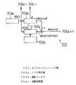
図12は、従来の技術による能動型騒音低減装置の他の例の構成を示す図である。図に示すように、能動型騒音低減装置700において、マイクロホン701は自動車室内の所定の位置に配置された、音の入力を受け付ける手段、定期的指示部704はスイッチ705a、705bを切換える手段、スイッチ705a、705bは騒音制御部702とオフライントレーニング部703との切り替えを行う手段、スピーカ706は自動車室内の所定の位置に配置された、音波を発するための手段、アンプ707a、707bは増幅用の手段、708aおよびbはローパスフィルタ(LPF)、A/Dコンバータ709はアナログ−デジタル変換を行う手段、D/Aコンバータ710はデジタル−アナログ変換を行う手段である。
【0018】
また、図13は能動型騒音低減装置700の騒音制御部702の構成を示す図であり、図に示すように、702aは適応フィルタ、702bは係数更新器、702c、702dは伝達特性模擬部、702eは加算器である。
【0019】
また、図14は能動型騒音低減装置700のオフライントレーニング部703の構成を示す図であり、図において、図13と同一名称は同一部で、ノイズ発生器703aは適応フィルタ703bにノイズを出力する手段、703eはROMである。さらに、図15は能動型騒音低減装置700のオフライントレーニング部703の第2例の構成を示す図であり、図において、図13および14と同一名称は同一部で、703fはEEPROMである。
【0020】
以上のような構成を有する従来の技術による能動型騒音低減装置の動作について、以下、説明を行う。
【0021】
はじめに、スイッチ705a、705bは騒音制御部702を接続しているものとする。自動車室内でエンジン音などの騒音が発生すると、マイクロホン701は該騒音を検出して、これを検出信号としてアンプ707aに出力する。アンプ707aは検出信号を増幅し、次いでLPF708aは検出信号の周波数帯域を制限して、高域成分を除去する。さらにA/Dコンバータ709は検出信号をデジタル信号に変換して、騒音制御部702へ出力する。
【0022】
騒音制御部702は信号に所定の処理を行い、これを騒音制御信号として、D/Aコンバータ710へ出力する。D/Aコンバータは騒音制御信号をアナログ信号に再変換する。LPF708bは、アナログ信号となった騒音制御信号から高域成分を取り除く。アンプ707bは制御信号の増幅を行い、スピーカ706はこれを騒音制御音として自動車室内に出力する。
【0023】
騒音制御音はマイクロホン701の配置された個所の近傍で騒音と干渉を起こし、その結果干渉音を生成する。この干渉音はマイクロホン701によって検出され、上記の騒音と同様の処理を施され、新たな制御音としてスピーカ706から出力される。
【0024】
このように、図12に示す能動型騒音低減装置はフィードバック構成となっており、一連の動作を繰り返すことにより雑音の消去を行う。
【0025】
次に、図13を参照しながら、騒音制御部702における検出信号処理の動作を説明する。スイッチ705aを介して入力した検出信号は、係数更新器702bと減算器702eとにそれぞれ入力される。
【0026】
はじめに減算器702e側の動作を説明する。減算器702eは、上述した検出信号と、伝達特性模擬部702dからの出力とを受けると、検出信号から、伝達特性模擬部702dからの出力を減算して、これを騒音信号として、適応フィルタ702aと伝達特性模擬部702cとに出力する。
【0027】
係数更新器702bでは、伝達特性模擬部702cから出力された信号とスイッチ705aからの検出信号に基づき、スイッチ705aからの検出信号を最小とするように適応フィルタ702aのフィルタ係数を更新する。適応フィルタ702aは、更新されたフィルタ係数と騒音信号との入力を受けると、これら信号を畳込み処理して騒音制御信号を生成し、スイッチ705bを介してD/Aコンバータ710へ出力する。
【0028】
ここで、騒音制御部702で用いられている伝達特性模擬部705c、705dのフィルタ係数の同定について説明を行う。定期的指示部704は、タイマ、イグニッションスイッチ(IGSW)、A/Dコンバータ709の出力に接続され、時間情報、エンジン停止情報、外部騒音レベルにより、定期的かつ自動的に同定する。同定時は、定期的指示部704からの信号により、スイッチ705a、705bはオフライントレーニング部703に接続される。
【0029】
オフライントレーニング部703の動作を図14および図15を用いて詳しく説明する。図14において、定期的指示部704から同定が許可されれば、ノイズ発生器703aはテスト信号W(n)をスイッチ705bを介してスピーカ706から再生すると共に、適応フィルタ703bと係数更新器703cへ入力する。適応フィルタ703bで信号処理されたテスト信号W(n)Hd’が、減算器703dに入力される。
【0030】
一方、スイッチ705aを介してマイクロホン701で検出したテスト信号W(n)Hdが減算器703dに入力すると、減算器703dは、該テスト信号W(n)Hdから適応フィルタ703bからの入力であるテスト信号W(n)Hd’を減算し、減算結果W(n)(−Hd’+Hd)を係数更新器703cに入力する。係数更新器703cは、ノイズ発生器703aからのテスト信号W(n)と減算器703dからの信号W(n)(−Hd’+Hd)の入力をうけると、これら信号に基づき、減算器703dからの信号W(n)(−Hd’+Hd)を最小にするように適応フィルタ703bの係数を更新する。更新された適応フィルタ703bの係数を伝達特性模擬部702c、702dに入力する。
【0031】
このように、騒音制御部702で使用する伝達特性模擬部702c、702dのフィルタ係数が同定されることになるが、同定を始める係数更新器703cの初期値をROM703eに予め記憶された係数とすることにより、同定時間を短くすることができる。さらに、図15に示すように、ROM703eをEEPROM703fに置き換えることにより、適応フィルタ703bで同定した係数をEEPROM703fに記憶させて、次回同定時にその係数を初期値とすることにより、同定時間を短縮することができる。
【0032】
上述した騒音制御部702の動作は、図11または図12に示した能動型騒音低減装置の技術である Filtered-x LMSアルゴリズムを基本として、検出マイクロホンを1つとしたフィードバック構成によるものであって、これにより、エンジン音のような周期的騒音を自動車室内で低減することができる。
【0033】
【発明が解決しようとする課題】
しかしながら図11に示す従来の技術による能動型騒音低減装置においては、伝達特性同定の作業は車室内における乗員の有無あるいは乗員の意志に関わらず行われるため、乗員が乗車しているとき伝達特性同定が行われた場合、乗員は非常に耳障りなテスト信号を聞くことになってしまうという問題があった。
【0034】
また、スピーカやマイクの不良などドアと窓の開閉状態以外の異常により、誤ったフィルタ係数に更新されてしまうと、その後の騒音制御動作を不安定なものとする問題点もあった。
【0035】
さらに、能動騒音制御の対象となる騒音は、主に低周波領域を対象としているため、システムのサンプリング周波数が低めに設定されることが多く、必然的に同定時間はかなり長くなる傾向にある。そこでフィルタ係数を精度よく同定するためには長い同定時間が必要となり、乗員は長時間耳障りなテスト信号を聞くことに耐えねばならないという問題点があった。
【0036】
加えて、テスト信号が大きすぎると乗員および車外の周囲環境に苦痛を与えるし、逆に小さすぎると暗騒音にマスキングされてしまい、精度のよい同定ができないという問題点もあった。
【0037】
また、図12に示す能動型騒音低減装置によれば、書換え可能なメモリにおいて、新たに同定した係数を以前の係数に上書きする構成として次回同定時の初期値とすることにより、同定した係数に誤差が多い場合や、正常に記憶されなかった場合など、係数異常により、精度よく、あるいは安定に騒音制御できないという問題点もあった。
【0038】
本発明は、このような問題に鑑みてなされたものであり、自動車室内に乗員がいないときに伝達特性の同定を行うことを可能とする能動型騒音低減装置を得ることを目的とする。
【0039】
【課題を解決するための手段】
上記の目的を達成するために、第1の本発明は、自動車室内の騒音と関連した参照信号を検出する参照信号検出器と、
前記参照信号を信号処理することにより、騒音を低減するための制御信号を出力する信号処理器と、
前記信号処理器の出力を再生するスピーカと、
誤差検出器と、
前記参照信号と前記誤差検出器からの検出信号とを用いて、前記誤差検出器の検出信号を最小とするように、前記信号処理器の係数を更新する係数更新器と、
前記スピーカから前記誤差検出器までの伝達特性を同定するモデル同定器とを備え、
前記モデル同定器は、自動車室内の乗員がいないこと又は乗員がいない可能性が高いと判定する判定手段を有し、該判定手段が自動車室内の乗員がいないこと又は乗員がいない可能性が高いと判定したときに前記同定を行い、
前記同定で求めた伝達特性を書き換え可能なメモリに記憶する構成とし、該伝達特性と予め不揮発性メモリに記憶しておいた伝達特性とを前記能動型騒音低減装置の制御中に選択可能としたことを特徴とする能動型騒音低減装置である。
また、第2の本発明は、前記参照信号検出器は自動車走行時の騒音を検出するものであって、
前記モデル同定器は、前記スピーカから前記参照信号検出器までの伝達特性も同定することを特徴とする第1の本発明の能動型騒音低減装置である。
また、第3の本発明は、前記誤差検出器または前記参照信号検出器からの信号が所定レベル以下のとき、前記同定を行うことを特徴とする第1の本発明の能動型騒音低減装置である。
また、第4の本発明は、前記判定手段は、乗員がいない可能性が高い時間帯であるか否かにより判定を行うことを特徴とする第1の本発明の能動型騒音低減装置である。
また、第5の本発明は、前記判定手段は、運転席のドアが開いてから閉じられることを検知することにより判定を行うことを特徴とする第1の本発明の能動型騒音低減装置である。
また、第6の本発明は、エンジンの起動回数を計測しておき、該計測回数が所定回数に達したときに前記同定を行うことを特徴とする第1の本発明の能動型騒音低減装置である。
また、第7の本発明は、前記判定手段は、キーシリンダにキーを挿し込んで回動させたことによるか、またはトランスミッタからのキーレスロック信号を受信したことによってドアがロックされたことを検出することにより判定することを特徴とする第1の本発明の能動型騒音低減装置である。
また、第8の本発明は、基準レベル設定器と、レベル比較器と、レベル調整器とをさらに備え、
前記基準レベル設定器は、ある所定の強さの信号である基準レベル信号を出力し、
前記レベル比較器は、前記基準レベル信号と前記誤差検出器の検出信号との入力を受け、前記基準レベル信号と前記誤差検出器の検出信号のレベルとを比較した結果を比較信号として出力し、
前記レベル調整器は、前記比較信号に基づいて、前記不揮発性メモリに記憶しておいた伝達特性のレベルのみを調整し、調整後の前記伝達特性を前記書き換え可能なメモリに書き込むことを特徴とする第1の本発明の能動型騒音低減装置である。
また、第9の本発明は、前記同定時にモデル同定器から出力されるテスト信号は、自然界に存在する環境音を用いたことを特徴とする第1の本発明の能動型騒音低減装置である。
【0042】
【発明の実施の形態】
(実施の形態1)
図1は本発明の実施の形態1による能動型騒音低減装置の構成を示す図である。図に示すように、能動型騒音低減装置100において、マイクロホン1aは自動車室内の騒音を検出して適応フィルタ2およびフィルタ係数更新手段110へ入力する手段である。スイッチ10は、フィルタ係数更新手段110または伝達特性同定手段120からの出力を、同定動作制御手段11の制御によってスピーカ5へ入力する手段である。マイクロホン1bは、自動車室内の音の入力を、フィルタ係数更新手段110または伝達特性同定手段120へ入力するための手段である。
【0043】
次に、フィルタ係数更新手段110において、Fxフィルタ3は騒音制御のためのフィルタ係数を格納しており、マイクロホン1aからの入力をこのフィルタ係数により処理してLMS演算器4に入力する手段である。LMS演算器4は、Fxフィルタ3およびマイクロホン1bからの入力の処理を行い、適応フィルタ2へ入力する手段である。
【0044】
また、伝達特性同定手段120において、テスト信号発生器6はテスト信号を発生して適応フィルタ7およびLMS演算器8へ出力する手段である。適応フィルタ7はテスト信号およびLMS演算器8からの入力を受けてフィルタ係数を生成し、Fxフィルタ3へ出力する手段である。減算器9はマイクロホン1bおよび適応フィルタ7からの信号を減算して、その結果をLMS演算器8へ出力する手段である。
【0045】
なお、上記の構成において、マイクロホン1aは請求項記載の参照信号検出器、適応フィルタ2は請求項記載の信号処理器、マイクロホン1bは請求項記載の誤差検出器、LMS演算器4は請求項記載の係数更新器、伝達特性同定手段120は請求項記載のモデル同定器、同定動作制御手段11は請求項記載の判定手段にそれぞれ相当するものである。
【0046】
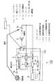
次に、図2は、能動型騒音低減装置100の同定動作制御手段11の内部構成を示す図である。図に示すように、同定動作許可判定器12は図1に示したスイッチ10に接続した手段である。車速センサ13は自動車の速度を測定する手段、エンジン停止センサ14はエンジンが停止しているか動作しているかを検出する手段、エンジン起動カウンタ15はエンジンの起動回数を計数する手段、着座センサ16は自動車室内の座席に設けられた手段、同定スイッチ17は利用者によってオンオフが切り替えられる装置、開閉状態検出センサ18は自動車室内の乗車席やトランクのドアの開閉状態を検出する手段、騒音レベル&誤差信号レベル検出器19はマイクロホン1aおよび1bを用いて、自動車室内の騒音信号および誤差信号のレベルを検出する手段、タイマ20は時間を計測する手段、走行距離カウンタ21は自動車の走行距離を検出する手段で、13〜21の各手段および各装置はいずれも同定動作許可判定器12に対してそれぞれ独立に接続している。
【0047】
以上の構成を有する、本発明の実施の形態1による能動型騒音低減装置の動作について、以下説明を行う。
【0048】
はじめに、騒音制御動作について説明する。このとき同定動作制御手段11は、スイッチ10を端子aの方に接続するよう制御を行う。次にマイクロホン1aは、自動車室内の騒音を検出する。マイクロホン1aによって検出された騒音は、騒音信号として適応フィルタ2およびFxフィルタ3にそれぞれ出力される。
【0049】
適応フィルタ2は、騒音信号の入力を受けると、これにフィルタ係数を畳み込んで制御信号を生成してこれをスピーカ5へ出力する。
【0050】
適応フィルタ2からの制御信号は、スイッチ10を介し、スピーカ5へ入力する。スピーカ5は、制御信号を実際の音である制御音として自動車室内に出力する。
【0051】
自動車室内では、制御音と、騒音源から発生した騒音とが干渉を起こして、新たな音波信号が生成される。マイクロホン1bは、この音波信号を検出すると、これを誤差信号としてLMS演算器4へ出力する。
【0052】
一方、Fxフィルタ3は、騒音信号の入力を受けると、これとフィルタ係数との畳み込み演算を行い、得られた信号をLMS演算器4に出力する。
【0053】
LMS演算器4は、Fxフィルタ3から入力した信号と、マイクロホン1bから入力した誤差信号とを受けると、これら信号に基づき、誤差信号のレベルを最小とするように適応フィルタ2のフィルタ係数を更新するための係数更新信号を生成し、適応フィルタ2へ出力する。適応フィルタ2は、係数更新信号の入力を受けると、格納しているフィルタ係数を更新する。以上の動作を繰り返して行うことにより、自動車室内の騒音を消去することができる。
【0054】
以上の騒音制御動作において、Fxフィルタ3には、スピーカ5からマイクロホン1bまでの伝達特性があらかじめ同定され、フィルタ係数として設定されている。この同定の動作は伝達特性同定手段120を構成する、テスト信号発生器6、適応フィルタ7、LMS演算器8および減算器9によって行われるものであり、従来の技術による能動型制御装置と同様にFiltered-x LMSアルゴリズムに基づいている。以下、伝達特性同定手段120による、伝達特性の同定について説明を行う。
【0055】
はじめに、同定動作制御手段11はスイッチ10を端子bに接続するよう制御を行う。次いで、テスト信号発生器6はテスト信号であるホワイトノイズを発生し、スピーカ5、適応フィルタ7およびLMS演算器8へそれぞれ出力する。
【0056】
スピーカ5は、ホワイトノイズの入力を受けると、これを自動車室内に出力する。マイクロホン1bはホワイトノイズを検出すると、これを検出信号として、減算器9に出力する。
【0057】
一方、適応フィルタ7は、ホワイトノイズの入力を受けると、これを処理して減算器9に出力する。減算器9は、検出信号および適応フィルタ7から出力した信号を受けると、検出信号から適応フィルタ7の出力を減算し、その結果をLMS演算器8に出力する。
【0058】
LMS演算器8は、ホワイトノイズと、先の減算結果との入力を受けると、これら信号に基づき、減算結果を最小にするように適応フィルタ7のフィルタ係数を更新するための信号を生成し、適応フィルタ7へ出力する。
【0059】
適応フィルタ7はLMS演算器8からの信号入力を受けると、スピーカ5からマイクロホン1bまでの伝達特性を同定してフィルタ係数として設定し、これをFxフィルタ3に出力する。ただし、このとき、適応フィルタ7の初期値は0となっている。
【0060】
最後に、Fxフィルタ3はフィルタ係数を格納して、フィルタ係数の設定は完了する。
【0061】
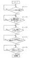
次に、同定動作制御手段11による、伝達特性同定動作の制御動作について説明を行う。図3および図4は、同定動作制御手段11の動作手順を示すフローチャートで、以下、図2、3および4を参照しながら、同定動作制御手段11の動作を説明する。
【0062】
はじめに、図3に示すステップ1において、同定動作許可判定器12は、エンジン停止センサ14の信号からエンジンが停止したかどうかを判定する。エンジンが停止したと判断すると、ステップ2へ進む。
【0063】
ステップ2において、同定動作許可判定器12は、騒音信号レベル&誤差信号レベル検出器19の信号から、マイクロホン1aが検出した騒音信号およびマイクロホン1bが検出した誤差信号がそれぞれ所定レベル以下であるかどうかを判定する。所定レベル以下であると判断すると、ステップ3へと進む。
【0064】
ステップ3において、同定動作許可判定器12は、開閉状態検出センサ18の信号から、自動車の、少なくとも1つのドアが一旦開いた後に閉じられたかどうかを判定する。上記の状態であると判断すると、ステップ4へと進む。
【0065】
ステップ4において、同定動作許可判定器12は、開閉状態検出センサ18の信号から、車外からドアをキーロックされたかどうかを判定する。開閉状態検出センサ18が検出する信号としては、キーシリンダにキーが挿し込まれ回動したことを検知する信号、またはトランスミッタからのキーレスロック信号が用いられる。キーロックが車外からされたと判断すると、ステップ5へと進む。
【0066】
ステップ5において、同定動作許可判定器12は、さらに同定スイッチ17がオンになっているかオフになっているかを検知する。同定スイッチ17がオンになっていることを検知すると、以下の動作条件がそろったことになる。すなわち、「エンジンが停止して、車室内暗騒音レベルは所定値以下となっており、ドアが1度開いてから閉じ、そしてドアが外部からロックされたので、おそらく運転手は降車し、さらに運転手の意志の下で伝達特性の同定は許可されている」という条件が満たされたこととなり、この条件に基づいて同定動作許可判定器12は、自動車室内に乗員はいないとの判断を下し、スイッチ10を端子bに接続するようにする。
【0067】
スイッチ10が端子bと接続されると、先に説明した伝達特性の同定が行われ、Fxフィルタ3のフィルタ係数が設定される。
【0068】
次に、同定動作制御手段11の動作条件の第2例を、図4を参照しながら説明する。
【0069】
はじめに、図4に示すステップ6において、同定動作許可判定器12は、エンジン起動カウンタ15の信号からエンジンの起動あるいは停止回数が所定回数に達しているかどうかを判定する。所定回数に達していると判断すると、ステップ7へ進む。
【0070】
ステップ7において、同定動作許可判定器12は、車速センサ13の信号から、自動車が停止状態にあるかどうかを判定する。自動車が停止状態であると判断すると、ステップ8へと進む。
【0071】
ステップ8において、同定動作許可判定器12は、タイマ20より自動車室内の時刻を検出し、現在時刻が夜間であるかどうかを判定する。夜間であると判断すると、ステップ9へと進む。
【0072】
最後にステップ9において、同定動作許可判定器12は、着座センサ16の信号から、自動車室内に乗員がいないかどうかの判定を行う。乗員がいないと判定すると、以下の判定条件がそろったことになる。すなわち、「所定回数自動車を使用したところで、自動車は停止しており、時間が十分経過して夜間であってさらに自動車室内には乗員はいない」との条件が満たされたこととなり、同定動作許可判定器12は、この条件に基づいて、スイッチ10を端子bに接続して、Fxフィルタ3のフィルタ係数設定のための伝達特性の同定を開始する。
【0073】
このように、本発明の実施の形態1の能動型騒音低減装置によれば、同定動作制御手段11が、各種センサを用いて自動車室内の乗員の有無を判定した後に、伝達同定の動作を行わせるようにしたことにより、自動車の利用者が自動車室内にいないときにテストを行い、該利用者がテスト信号であるホワイトノイズを耳にする可能性を極力低減することができる。
【0074】
また、本実施の形態1の能動型騒音低減装置によれば、Fxフィルタ3の係数を再同定可能としたことにより、スピーカ5やマイクロホン1bの経年変化などに対応して係数を改めることができるため、常にFxフィルタ3に格納した係数を精度よく求めることができるので、消音効果を常に良好な水準で保つことができる。
【0075】
また、同定動作制御手段11の同定開始条件は、本実施の形態においては、図3および図4のフローチャートとして示したが、同定開始条件は、もちろんこれらに限定されるものではなく、車速センサ13、エンジン停止センサ14、エンジン起動カウンタ15、着座センサ16、同定スイッチ17、開閉状態検出センサ18、騒音信号レベル&誤差信号レベル検出器19、タイマ20、走行距離カウンタ21からの情報を、利用状況に応じて適宜組み合わせることにより、車室内の乗員の有無を判定できるようにすればよい。
【0076】
また、着座センサ16の具体的な一例としては、図5(a)(b)および図6に示すように、自動車の各座席の座部内に設置されている圧力センサ16a〜16dと、各座席の背部内に設置されている圧力センサ16e〜16hと、各座席頭上の天井部内に設置されている赤外線センサ16i〜16lと、各座席横のドア部内に設置されている赤外線センサ16m〜16pとから構成されたものがある。
【0077】
このような構成を有する着座センサ16においては、圧力センサ16a〜16dおよび16e〜16hが座席に加えられる圧力を検知せず、また、赤外線センサ16e〜16hおよび16m〜16pが車内に異物を検知しない旨の情報が得られた場合、同定動作許可判定器12は自動車室内に乗員がいないという判断を行う。ここで、着座センサ16として上述の圧力センサおよび赤外線センサ16a〜16pのすべてが必要であるというわけではなく、利用状況に応じて圧力センサ16a〜16hのみ、座部内圧力センサ16a〜16dのみ、あるいは赤外線センサ16i〜16pのみなどというふうに、各センサの種類、個数、および設置個所を適宜に選択、組み合わせて用いればよい。
【0078】
また、本実施の形態1では、エンジン起動カウンタ15は、エンジンの起動回数を計測するものとしたが、能動型騒音低減装置100自体の起動回数を計測してもよい。
【0079】
また、本実施の形態1では、テスト信号発生器6より出力するテスト信号は、ホワイトノイズとしたが、これに限定するものではなく、波の音や風の音などの環境音や一般の音楽でもよい。
【0080】
また、本実施の形態1においては、テスト信号のレベルについて特に具体的な規定を行わなかったが、テスト信号は、騒音信号レベル&誤差信号レベル検出器19で検出した騒音信号レベルおよび誤差信号レベルと比較して、フィルタ係数同定に必要な最小限のレベルとなるように調整することができる。これにより、自動車外部に漏れるテスト信号音を最小限に抑えると共に、常に必要とされるS/N比(暗騒音レベルとテスト信号レベルの比)を確保できるので精度のよい伝達特性を得られ、良好なフィルタ係数を同定できる。
【0081】
また、本実施の形態では騒音制御動作で使用する適応フィルタ2およびLMS演算器4と、同定動作で使用する適応フィルタ7およびLMS演算器8をそれぞれ別個に構成されているように説明したが、これは1つの適応フィルタと1つのLMS演算器を共用した構成として、騒音制御動作と同定動作とに応じて使い分けて用いるようにしてもよく、これにより、演算量やメモリ容量を削減することができる。
【0082】
なお、本実施の形態1において言及した誤差信号は、請求項記載の検出信号に相当するものである。
(実施の形態2)
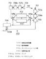
図7は本発明の実施の形態2による能動型騒音低減装置の構成を示す図である。図に示すように、図1と同一名称は同一部で、伝達特性同定手段130は、実施の形態1の伝達特性同定手段120にフィルタ係数記憶手段130aを付加した手段である。またフィルタ係数記憶手段130aにおいて、スイッチ10bは同定動作制御手段11によって制御される手段、書換え可能なメモリ(EEPROM)22と不揮発性メモリ(ROM)23とは、Fxフィルタ3と適応フィルタ7との間に、スイッチ10bを介して選択的に接続できるよう配置されている手段である。
【0083】
以上のような構成を有する本実施の形態2による能動型騒音低減装置について、以下その動作について説明する。
【0084】
本実施の形態2の能動型騒音低減装置200の動作は、基本的には本実施の形態1と同様であり、以下、通常の騒音制御の動作および、Fxフィルタ3のフィルタ係数を設定するための伝達特性同定の動作のそれぞれについて、本実施の形態1との相違点を中心に説明を行う。
【0085】
はじめに、同定動作制御手段11は、スイッチ10aを端子bに、また、スイッチ10bを端子cにそれぞれ接続して、伝達特性同定の動作を実行させる。これ以後、適応フィルタ7におけるフィルタ係数の設定までは、本実施の形態1と同様に行われる。
【0086】
次に、適応フィルタ7で設定されたフィルタ係数は、EEPROM22に出力、記憶される。一方、ROM23には、予めスピーカ5からマイクロホン1bまでの伝達特性を同定した所定の値のフィルタ係数が記憶されている。
【0087】
次に、騒音制御動作について説明する。同定動作制御手段11はスイッチ10bをc側に接続すると、Fxフィルタ3にはEEPROM22に記憶されたフィルタ係数が格納される。この場合は、本実施の形態1と同様の騒音制御が実行され、Fxフィルタ3に常に最新のフィルタ係数を格納するようにして、騒音制御を精度よく安定に実行することができる。
【0088】
次に、同定動作制御手段11がスイッチ10bを端子dに接続すると、ROM23に予め記憶されたフィルタ係数がFxフィルタ3に格納される。騒音制御動作において、EEPROM22に記憶したフィルタ係数が、実際の伝達特性と異なる特性のフィルタ係数であったり、フィルタ係数に含まれるデータにエラーがあるなどの異常があった場合、騒音制御動作に悪影響を与えるおそれがあるが、ROM23に記憶されたフィルタ係数は定数であるので、騒音制御動作に極端に悪影響を及ぼすことはない、
したがって、たとえEEPROM22が記憶しているフィルタ係数に不具合があったとしても、同定動作制御手段11が、スイッチ10bの切り替えを行うことにより、ROM23からあらかじめ定めたフィルタ係数を格納させてやることで、異常動作を回避して、良好な騒音制御動作を実行することができる。
【0089】
また、スピーカ5からマイクロホン1bまでの伝達特性を再同定する場合、通常、適応フィルタ7はいったん初期化されるが、ROM23に記憶されたフィルタ係数を初期値として設定することにより、ROM23のフィルタ係数からの変化分のみを計測することで伝達特性の同定を行うことができ、同定時間を短縮することができる。
【0090】
なお、本実施例ではEEPROM22とROM23の二つのメモリを使用する構成としたが、EEPROM22だけを用いて、ROM23に予め記憶されているフィルタ係数をEEPROM22のある領域に記憶しておき、再同定時には、その領域以外に新たなフィルタ係数を記憶するようにしてもよい。つまり、EEPROM22内に、読み出し専用の領域と読み書き可能な領域を分離して使用する構成としてもよい。
(実施の形態3)
図8は本発明の実施の形態3による能動型騒音低減装置の構成を示す図である。図において、図1および図7と同一名称は同一部で、伝達特性同定手段140において、基準レベル設定器24はある信号の所定のレベルを記録している手段である。また、レベル比較器25は基準レベル設定器24およびマイクロホン5bからの入力を受ける手段である。さらにレベル調整器26はROM23に記録されたフィルタ係数を取得するための手段である。
【0091】
以上のような構成を有する本実施の形態3による能動型騒音低減装置について、以下その動作について説明する。
【0092】
はじめに、予めFxフィルタ3にスピーカ5からマイクロホン1bまでの伝達特性が同定されており、フィルタ係数として設定されているものとして、騒音制御動作を行う場合は、本実施の形態1および2の騒音制御動作と同様の動作を行う。
【0093】
次に、Fxフィルタ3で用いられるフィルタ係数を設定するための、伝達特性の同定動作について説明を行う。はじめに、同定動作制御手段11はスイッチ10をb側に接続するよう制御を行う。次いで、テスト信号発生器6はテスト信号であるホワイトノイズを発生し、スピーカ5へそれぞれ出力する。スピーカ5は、ホワイトノイズの入力を受けると、これを自動車室内に出力する。マイクロホン1bはホワイトノイズを検出すると、これを検出信号としてレベル比較器25へ入力する。
【0094】
一方、基準レベル設定器からはある所定の強さの信号である基準レベル信号がレベル比較器25へ入力する。
【0095】
レベル比較器25は、基準レベル信号と、検出信号との入力を受けると、両者のレベルを比較して、その結果を比較信号としてレベル調整器26へ入力する。
【0096】
レベル調整器26には、ROM23から予め記憶されているフィルタ係数が格納されているが、レベル調整器26は、比較信号の入力を受けると、これに基づいて格納されたフィルタ係数のレベルのみを調整し、このレベルを調整されたフィルタ係数をEEPROM22に書き込む。これ以後の動作は、本実施の形態2の能動型騒音低減装置と同様に行われ、Fxフィルタ3にフィルタ係数が格納される。
【0097】
このように、本発明の実施の形態3の能動型騒音低減装置によれば、フィルタ係数同定のための手段を、基準レベル設定器24、レベル比較器25、レベル調整器26から構成し、ROM23に記憶されたフィルタ係数を基にしてそのレベルのみを調整することにより、伝達特性の同定を極めて短時間で行うことができる。
【0098】
また、スピーカ5およびマイクロホン1bは経年変化によって特性が変動するものであるが、騒音制御動作に影響を与えるのは主にレベルのみの変動であるため(騒音制御が不可能となるほど位相が変化することは希である)、本実施の形態3の能動型騒音低減装置によれば、スピーカやマイクロホンの特性が変化した場合でも精度のよい騒音制御を実行することができる。
【0099】
なお、本実施の形態3では、ROM23とEEPROM22とは別個の構成としたが、これは本実施の形態2と同様に、EEPROM22内に、読み出し専用の領域と読み書き可能な領域を分離して使用する構成としてもよく、この場合、レベル調整器26はEEPROM22に対してフィルタ係数の読み出しおよび書き込みを行う。
(実施の形態4)
図9は本発明の実施の形態4による能動型騒音低減装置の構成を示す図である。図に示すように、図1および図7と同一名称は同一部で、フィードバックキャンセル手段150は、伝達特性同定手段140aと同様の構成に加えて、さらにフィードバックキャンセラ27をスイッチ10aと減算器28との間に接続するように設けるとともに、減算器28をマイクロホン1aと、適応フィルタ2およびFxフィルタ3との間に配置した手段である。
【0100】
以上のような構成を有する本実施の形態4の能動型騒音低減装置の動作について、以下に説明を行う。
【0101】
はじめに騒音制御動作について説明する。本実施の形態1と同様にして、マイクロホン1aは騒音を検出すると、これを騒音信号として、減算器28を介して適応フィルタ2およびFxフィルタ3へ入力する。適応フィルタ2は騒音信号から制御信号を生成すると、スイッチ10を介してスピーカ5に出力し、スピーカ5は制御信号を制御音として自動車室内へ出力する。
【0102】
このとき、スピーカ5から出力した制御音が、マイクロホン1aへ音響フィードバックを起こしている場合、スピーカ5からの制御音は伝達特性Hを持つものとしてマイクロホン1aで検出される。すなわち、マイクロホン1aにおいては、騒音源からの騒音と、スピーカ5からの制御音とが混ざって検出されることになる。
【0103】
一方、適応フィルタ2から出力された制御信号は、スイッチ10aを介してフィードバックキャンセラ27にも入力する。このフィードバックキャンセラ27には、予めスピーカ5からマイクロホン1aまでの伝達特性が同定されてフィルタ係数として設定されており、フィードバックキャンセラ27は、このフィルタ係数を用いて制御信号の畳込み処理を行い、減算器28へ出力する。
【0104】
減算器28は、フィードバックキャンセラ27の入力を受けると、マイクロホン1aで検出した騒音から上記の入力を減算して、騒音信号から音響フィードバック分を取り除く。これにより減算器28から出力する信号は、騒音源からの騒音信号だけになる。
【0105】
なお、スピーカ5からの制御音の出力、マイクロホン5bによる誤差信号の検出以降の動作は、本実施の形態2と同様にして行われる。
【0106】
次に伝達特性同定の動作を説明する。
【0107】
本実施の形態4による能動型騒音低減装置400の伝達特性同定の動作は、伝達特性同定手段140aによるスピーカ5−マイクロホン1b間の伝達特性の同定と、フィードバックキャンセル手段140bによるスピーカ5−マイクロホン1a間の伝達特性の同定とに分けられるが、伝達特性同定手段140aの動作は、本実施の形態2による能動型騒音低減装置の伝達特性同定手段130と同様に行われるので、この説明は省略し、以下、フィードバックキャンセル手段140bによるスピーカ5−マイクロホン1a間の伝達特性の同定動作を説明する。
【0108】
はじめに、これまでの実施の形態と同様、同定動作制御手段11はスイッチ10aを端子bに接続するよう制御を行う。次にテスト信号発生器6はテスト信号であるホワイトノイズを、スピーカ5を介して出力する。スピーカ5から出力されたホワイトノイズは、マイクロホン1aで検出され、減算器9bに入力する。
【0109】
一方、テスト信号発生器6から出力されたホワイトノイズは、適応フィルタ7bおよびLMS演算器8bに入力される。適応フィルタ7bは、ホワイトノイズを処理してこれを制御信号として減算器9bへ出力する。減算器9bは、マイクロホン1bの検出信号から適応フィルタ7bの出力を減算し、その結果をLMS演算器8bに入力する。
【0110】
LMS演算器8bは、ホワイトノイズと、上記の減算結果との入力を受けると、これら信号に基づき、減算結果を最小にするように適応フィルタ7bのフィルタ係数を更新するための信号を生成し、適応フィルタ7bへ出力する。適応フィルタ7bは、LMS演算器8bからの入力を受けると、これに基づきフィルタ係数を更新する。
【0111】
このようにして、スピーカ5−マイクロホン1a間の伝達特性が同定されると、これを元に設定されたフィルタ係数は適応フィルタ7bに格納される。このフィルタ係数をさらにEEPROM22bに記憶して、フィードバックキャンセラ27のフィルタ係数として設定する。
【0112】
以上のように、本実施の形態4の能動型騒音低減装置によれば、スピーカ5からマイクロホン1aへの音響フィードバックが存在するときにも、フィードバックキャンセラ27と減算器28により、マイクロホン1aで検出した信号からスピーカ5からの制御信号を除去し、騒音源からの騒音信号だけを検出することができ、良好な騒音制御を行うことができる。
【0113】
なお、上記の動作によれば、フィルタ係数はフィードバックキャンセル手段150を動作させることによって取得したが、これはもちろん、実施の形態2の伝達特性同定手段130と同様に、ROM23bに記録されている、定数のフィルタ係数をフィードバックキャンセラ27に出力するようにしてもよい。
【0114】
また、フィードバックキャンセル手段150は、ここでは実施の形態2の伝達特性同定手段130と同等の構成としたが、これは実施の形態3の伝達特性同定手段140と同様に、基準レベル設定器、レベル比較器およびレベル調整器を備えた構成として、伝達特性のレベル変化のみを同定してフィルタ係数をする設定するものとしてもよい。また、実施の形態1の伝達特性同定手段120と同様に、適応フィルタ7bから出力したフィルタ係数を、直接フィードバックキャンセラ27に格納するようにしてもよい。
(実施の形態5)
図10は本発明の実施の形態5の能動型騒音低減装置の構成を示す図である。図に示すように、能動型騒音低減装置500において、図1および図9と同一名称は同一部であり、スイッチ10cは同定動作制御手段11によって制御される、テスト信号発生器6の出力先を切換えるための手段である。本実施の形態5の能動型騒音低減装置は、騒音検出器として一対のマイクロホン1a、1c、出力器としてスピーカ5a、5bおよび誤差信号検出器としてマイクロホン1b、1dを備えていて、2つの騒音源から発生する騒音を、2つの制御音により消音するようにしたものである。
【0115】
以上のように構成された本実施の形態5の能動型騒音低減装置500の動作を以下に説明する。
【0116】
まず騒音制御動作について説明する。基本的な動作は本実施の形態1と同様にして行われるが、騒音検出はマイクロホン1a、1cにおいて平行して行われる。
【0117】
はじめに、同定動作制御手段11は、スイッチ10aおよび10bを、いずれも端子aに接続するようにする。次いでマイクロホン1aは騒音を検出すると、これを騒音信号として、減算器28aを介して適応フィルタ2a、2bおよびFxフィルタ3a、3b、3c、3dへ入力する。適応フィルタ2a、2bは騒音信号から制御信号を生成すると、加算器30a、加算器30bへそれぞれ入力する。
【0118】
一方、マイクロホン1cは騒音を検出すると、これを騒音信号として、減算器28bを介して適応フィルタ2c、2dおよびFxフィルタ3e、3f、3g、3hへ入力する。適応フィルタ2c、2dは騒音信号から制御信号を生成すると、加算器30a、加算器30bへそれぞれ入力する。
【0119】
加算器30aは、適応フィルタ2a、2cから入力した制御信号を加算して、スイッチ10aを介してスピーカ5aへ出力する。スピーカ5aは制御信号を制御音として自動車室内へ出力する。
【0120】
また、加算器30bは、適応フィルタ2b、2dから入力した制御信号を加算して、スイッチ10bを介してスピーカ5bへ出力し、スピーカ5bは制御信号を制御音として自動車室内へ出力する。
【0121】
ところで上述の動作においては、マイクロホン1aおよび1cのいずれも、スピーカ5aおよび5bからの制御音を検出して音響フィードバックを生ずるおそれがある。以下、その場合の音響フィードバックの処理について、騒音検出側のマイクロホン毎に説明する。
【0122】
はじめに、マイクロホン1aがスピーカ5aからの制御音によって音響フィードバックを起こしている場合は、加算器30aを介して出力された制御信号は、スピーカ5aに入力する一方、フィードバックキャンセラ27aにも入力している。このフィードバックキャンセラ27aには、予めスピーカ5aからマイクロホン1aまでの伝達特性が同定されてフィルタ係数として設定されており、フィードバックキャンセラ27は、このフィルタ係数を用いて制御信号の畳込み処理を行い、減算器28aへ出力する。
【0123】
減算器28aは、フィードバックキャンセラ27の入力を受けると、マイクロホン1aで検出した騒音から上記の入力を減算して、騒音信号からスピーカ5aに起因する音響フィードバック分を取り除く。これにより減算器28から出力する信号は、騒音源からの騒音信号だけになる。
【0124】
次に、マイクロホン1aがスピーカ5bからの制御音によって音響フィードバックを起こしている場合は、加算器30bを介して出力された制御信号は、スピーカ5bに入力する一方、フィードバックキャンセラ27bにも入力している。このフィードバックキャンセラ27bには、予めスピーカ5bからマイクロホン1aまでの伝達特性が同定されてフィルタ係数として設定されており、フィードバックキャンセラ27bは、このフィルタ係数を用いて制御信号の畳込み処理を行い、減算器28aへ出力する。減算器28aは、フィードバックキャンセラ27aの場合と同様に、フィードバックキャンセラ27bの入力を受けると、マイクロホン1aで検出した騒音から上記の入力を減算して、騒音信号からスピーカ5bに起因する音響フィードバック分を取り除く。
【0125】
一方、マイクロホン1cがスピーカ5aからの制御音によって音響フィードバックを起こしている場合は、フィードバックキャンセラ27c、減算器28bが上記フィードバックキャンセラ27a、減算器28aと同様の動作を行って、騒音信号から音響フィードバック分を取り除く。また、マイクロホン1cがスピーカ5bからの制御音によって音響フィードバックを起こしている場合は、フィードバックキャンセラ27d、減算器28bが上記フィードバックキャンセラ27b、減算器28aと同様の動作を行う。
【0126】
このように、フィードバックキャンセラ27aおよび27bが動作することによって、減算器28aの出力は、騒音源からの騒音信号だけとなり、スピーカ5a、5bからは純粋な制御信号が制御音として自動車室内へ出力される。
【0127】
さて、自動車室内では、スピーカ5a、5bから出力した制御音と、2つの騒音源から発生した騒音とが干渉を起こして、新たな音波信号が生成される。この音波信号の検出は、マイクロホン1b、1dにおいて平行して行われる。
【0128】
はじめに、マイクロホン1bは、上記の音波信号を検出すると、これを誤差信号としてLMS演算器4a、4c、4e、4gへ入力する。
【0129】
この一方で、Fxフィルタ3a、3c、3e、3gは、マイクロホン1a、1bから騒音信号の入力を受けると、これとフィルタ係数との畳み込み演算を行い、得られた信号をLMS演算器4a、4c、4e、4gにそれぞれ入力する。
【0130】
LMS演算器4a、4c、4e、4gは、それぞれFxフィルタ3a、3c、3e、3gから入力した信号と、上記の誤差信号とを受けると、これら信号に基づき、該誤差信号のレベルを最小とするように適応フィルタ2a、2bのフィルタ係数を更新するための係数更新信号を生成し、加算器29a、29b、29c、29dへそれぞれ入力する。
【0131】
次に、マイクロホン1b側の動作を説明する。マイクロホン1bは、上記の音波信号を検出すると、これを誤差信号としてLMS演算器4b、4d、4f、4hへ入力する。
【0132】
この一方で、Fxフィルタ3b、3d、3f、3hは、マイクロホン1a、1bから騒音信号の入力を受けると、これとフィルタ係数との畳み込み演算を行い、得られた信号をLMS演算器4b、4d、4f、4hにそれぞれ入力する。
【0133】
LMS演算器4b、4d、4f、4hは、それぞれFxフィルタ3b、3d、3f、3hから入力した信号と、上記の誤差信号とを受けると、これら信号に基づき、該誤差信号のレベルを最小とするように適応フィルタ2a、2bのフィルタ係数を更新するための係数更新信号を生成し、加算器29a、29b、29c、29dへそれぞれ入力する。
【0134】
次に、加算器29aは、LMS演算器4a、4bから係数更新信号の入力を受けると、これらを加算して適応フィルタ2aへ入力する。以下同様に、加算器29bは、LMS演算器4c、4dからの係数更新信号の入力を、加算器29cは、LMS演算器4e、4fからの係数更新信号の入力を、加算器29dは、LMS演算器4g、4hからの係数更新信号の入力をそれぞれ加算して、適応フィルタ2b、2c、2dへそれぞれ入力する。
【0135】
最後に適応フィルタ2a、2b、2c、2dは、それぞれ加算器29a、29b、29c、29dより係数更新信号の入力を受けると、これに基づき格納しているフィルタ係数を更新する。
【0136】
以上の動作を繰り返して行うことにより自動車室内の騒音は消去される。
【0137】
次に、各適応フィルタおよびFxフィルタにて用いられるフィルタ係数を設定するための、各スピーカ−マイクロホン間の伝達特性同定の動作について説明を行う。
【0138】
はじめに、スピーカ5aと、マイクロホン1b、マイクロホン1d、マイクロホン1aおよびマイクロホン1cとの間の伝達特性同定の動作を説明する。同定制御手段11は、スイッチ10cを端子cに接続するよう制御を行ってスイッチ10cを選択するとともに、スイッチ10aをb側に接続させる。
【0139】
次に、テスト信号発生器6はテスト信号であるホワイトノイズを、スピーカ5aを介して出力する。スピーカ5aから出力されたホワイトノイズは、マイクロホン1b、1dで検出信号として、マイクロホン1bからは減算器9a、9c、9e、9g、9i、9kに、マイクロホン1dからは減算器9b、9d、9f、9hにそれぞれ入力し、さらにマイクロホン1a、1cで雑音信号として、マイクロホン1aからは減算器9i、9jに、マイクロホン1cからは減算器9k、9lにそれぞれ入力する。
【0140】
一方、テスト信号発生器6から出力されたホワイトノイズは、適応フィルタ7aおよびLMS演算器8a、適応フィルタ7bおよびLMS演算器8b、適応フィルタ7eおよびLMS演算器8e、適応フィルタ7fおよびLMS演算器8f、適応フィルタ7iおよびLMS演算器8i、適応フィルタ7kおよびLMS演算器8kにもそれぞれ入力する。
【0141】
次に、上記の各部において、適応フィルタ7a、7b、7e、7f、7i、7kは、ホワイトノイズの入力を処理してこれを制御信号として、減算器9a、9b、9e、9f、9i、9kへそれぞれ出力する。さらに減算器9a、9b、9e、9f、9i、9kは、マイクロホン1a、1b、1cの検出信号から適応フィルタ7a、7b、7e、7f、7i、7kの出力をそれぞれ減算し、その結果をLMS演算器8a、8b、8e、8f、8i、8kにそれぞれ出力する。
【0142】
LMS演算器8a、8b、8e、8f、8i、8kは、それぞれテスト信号発生器6からのホワイトノイズと、上記の減算器9a、9b、9e、9f、9i、9kからの減算結果との入力を受けると、これら信号に基づき、減算結果を最小にするように適応フィルタ7a、7b、7e、7f、7i、7kのフィルタ係数を更新するための信号を生成し、適応フィルタ7a、7b、7e、7f、7i、7kへ出力する。最後に適応フィルタ7a、7b、7e、7f、7i、7kは、それぞれLMS演算器8a、8b、8e、8f、8i、8kからの入力を受けると、これに基づきフィルタ係数を更新する。
【0143】
以上の動作により、スピーカ5a−マイクロホン1b間、スピーカ5a−マイクロホン1d間、スピーカ5a−マイクロホン1a間、スピーカ5a−マイクロホン1c間の伝達特性が同定できると、これらを元にして設定されたフィルタ係数は、Fxフィルタ3a、3b、3e、3fおよびフィードバックキャンセラ27a、27cに格納される。
【0144】
次に、スピーカ5bと、マイクロホン1b、マイクロホン1d、マイクロホン1aおよびマイクロホン1cとの間の伝達特性同定の動作を行う場合は、同定制御手段11は、スイッチ10cを端子dに接続するよう制御を行ってスイッチ10dを選択するとともに、スイッチ10bを端子bに接続させる。この場合は、減算器9c、9d、9g、9h、9j、9l、適応フィルタ7c、7d、7g、7h、7j、7lおよびLMS演算器8c、8d、8g、8h、8j、8lが上記減算器9a、9b、9e、9f、9i、9k、適応フィルタ7a、7b、7e、7f、7i、7kおよびLMS演算器8a、8b、8e、8f、8i、8kと同様の動作を行うことにより、Fxフィルタ3c、3d、3g、3hおよびフィードバックキャンセラ27b、27dにフィルタ係数が格納される。
【0145】
このように、本実施の形態5の能動型騒音低減装置によれば、複数の騒音源を検出して、複数の制御信号によって騒音制御動作を行うことにより、自動車室内にて生ずる複合した騒音の低減を効果的に行うことができる。
【0146】
なお、本実施の形態において、騒音検出器または誤差検出器であるマイクロホンは2つとしたが、これは3つ以上としても良く、また騒音検出器と誤差検出器との数が同一である必要も無い。この場合は適応フィルタ、加算器等の各部の構成をさらに付加することによって、上記と同様の騒音制御の動作を実現できる。
【0147】
また、本実施の形態において、伝達特性同定手段の構成は、本実施の形態1と同様のものとして説明を行ったが、これはもちろん、本実施の形態2のように、EEPROMおよびROMか、EEPROMかを加えた構成として、定数のフィルタ係数を用いるようにしてもよく、また、本実施の形態3のように、基準レベル設定器、レベル比較器およびレベル調整器を有する構成として、伝達特性のレベルのみを調整してフィルタ係数の更新を行ってもよい。これはフィードバックキャンセル手段においても同様である。
【0148】
【発明の効果】
以上説明したところから明らかなように、本発明によれば、自動車室内に利用者がいない、またはいないと考えられる状態において、伝達特性同定の動作を自動的に行わせることができ、自動車の利用者が不快なテスト信号を耳にする機会を極力低減できる効果がある。
【0149】
また本発明によれば、マイクやスピーカといった機器の経時変化に基づく伝達特性同定時の異常動作を回避するとともに、伝達特性同定にかかる時間を短縮できる効果がある。
【図面の簡単な説明】
【図1】本発明の実施の形態1の能動型騒音低減装置の構成を示す図である。
【図2】本発明の能動型騒音低減装置における同定動作制御手段11の構成を示すブロック図である。
【図3】同定動作制御手段11の動作条件を示すフローチャートである。
【図4】同定動作制御手段11の動作条件の第2例を示すフローチャートである。
【図5】(a)自動車室内の着座センサの設置位置の一例を示す概念図である。
(b)自動車室内の着座センサの設置位置の一例を示す概念図である。
【図6】自動車室内の着座センサの一である赤外線センサの設置位置を示す概念図である。
【図7】本発明の実施の形態2の能動型騒音低減装置の構成を示す図である。
【図8】本発明の実施の形態3の能動型騒音低減装置の構成を示す図である。
【図9】本発明の実施の形態4の能動型騒音低減装置の構成を示す図である。
【図10】本発明の実施の形態5の能動型騒音低減装置の構成を示す図である。
【図11】従来の技術による能動型騒音低減装置の構成を示す図である。
【図12】従来の技術による能動型騒音低減装置の構成を示す図である。
【図13】従来の技術による能動型騒音低減装置の騒音制御部の構成を示す図である。
【図14】従来の技術による能動型騒音低減装置のオフライントレーニング部の構成を示す図である。
【図15】従来の技術による能動型騒音低減装置のオフライントレーニング部の第2例の構成を示す図である。
【符号の説明】
1a、1b、1c、1d、701 マイクロホン
2、2a、2b、2c、2d 7、7a、7b、7c、7d、7e、7f、7g、7h、7i、7j、7k、7l、606、702a 適応フィルタ
3、3a、3b、3c、3d、3e、3f、3g、3h Fxフィルタ
4、4a、4b、4c、4d、4e、4f、4g、4h、8、8a、8b、8c、8d、8e、8f、8g、8h、8i、8j、8k、8l LMS演算器
5、5a、5b、706 スピーカ
6 テスト信号発生器
9、9a、9b、9c、9d、9e、9f、9g、9h、9i、9j、9k、9l、 702e 減算器
10、10a、10b、10c、602、608a、608b、705a、705b スイッチ
11 同定動作制御手段
12 同定動作許可判定器
13 車速センサ
14 エンジン停止センサ
15 エンジン起動カウンタ
16、16a、16b、16c、16d、16e、16f、16g、16h、16i、16j、16k、16l、16m、16n、16o、16p 着座センサ
17 同定スイッチ
18 開閉状態検出センサ
19 騒音信号レベル&誤差信号レベル検出器
20 タイマ
21 走行距離カウンタ
22、22a、22b EEPROM
23、23a、23b、703e ROM
24 基準レベル設定器
25 レベル比較器
26 レベル調整器
27、27a、27b、27c、27d フィードバックキャンセラ
28、28a、28b 減算器
29a、29b、29c、29d 30a、30b 加算器
100、200、300、400、500、600、700 能動型騒音低減装置
110、605 フィルタ係数更新手段
120、130、140、140a 伝達特性同定手段
150 フィードバックキャンセル手段
601 騒音入力器
603、611a、611b、709 A/Dコンバータ
604デジタルフィルタ
607a、607b、710 D/Aコンバータ
609a、609b 騒音制御音出力器
610a、610b、610c 残留音入力器
612 テスト信号発生手段
40 車速センサ
702 騒音制御部
702b 係数更新器
702c、702d 伝達特性模擬部
702e 減算器
703 オフライントレーニング部
703a ノイズ発生器
703b 適応フィルタ
703c 係数更新器
703f EEPROM
704 定期的指示部
707a、707b アンプ
708a、708b ローパスフィルタ[0001]
BACKGROUND OF THE INVENTION
The present invention relates to an active noise reduction device used in an automobile.
[0002]
[Prior art]
In recent years, as a technology for reducing noise, active noise control for reducing noise by generating control sound having a phase opposite to noise from a speaker to cause noise has been put into practical use. Various silencers have been proposed for the purpose of reducing engine noise, such as those described in Japanese Patent Application Laid-Open No. 5-61486.
[0003]
FIG. 11 is a diagram showing a configuration of an active noise reduction device according to the prior art. As shown in the figure, in the active
[0004]
The conventional active noise reduction apparatus having the above configuration will be described below. Here, the noise source is an engine as an example, and the noise input device 601 is realized as, for example, a crank angle sensor. The noise input device 601 detects a reference signal indicating the state of noise from the noise source, and passes through a
[0005]
The A /
[0006]
When receiving the input of the reference signal, the
[0007]
Next, the noise control sound output from the noise control sound output devices 609a and 609b causes interference between the noise from the noise source and the residual sound input device. A sound wave signal generated as a result of interference between these two types of sound is input as residual sound to the residual
[0008]
The residual sound input to the residual
[0009]
On the other hand, the reference signal input to the
[0010]
Then, the filter coefficient update means 605 receives the input of the reference signal output from the
[0011]
The noise reduction techniques described above can be found in the Filtered-x LMS algorithm (see, eg, B. Widrow & SD Stearns, "Adaptive Signal Processing" (Prentice-Hall, Inc., New Jersey, 1985)) or Multiple Error Filtered-x LMS algorithm (eg reference; SJ Elliott, IM Stothers and PA Nelson, ("A multiple error LMS algorithm and its application to the active control of sound and vibration." IEEE Trans. Acoust. Speech Signal Process. ASSP- 35, pp 1423-1434 (1987)).
[0012]
By the way, before entering the actual noise control operation as described above, it is necessary to identify the filter coefficient of the
[0013]
First,
[0014]
Next, when the filter
[0015]
During the filter coefficient identification operation using the test signal described above, the filter
[0016]
Next, another example of the active noise reduction device according to the prior art is disclosed in Japanese Patent Application Laid-Open No. 8-6575.
[0017]
FIG. 12 is a diagram showing the configuration of another example of an active noise reduction device according to the prior art. As shown in the figure, in the active
[0018]
FIG. 13 is a diagram showing the configuration of the
[0019]
FIG. 14 is a diagram showing the configuration of the off-
[0020]
The operation of the conventional active noise reduction apparatus having the above configuration will be described below.
[0021]
First, it is assumed that the
[0022]
The
[0023]
The noise control sound causes interference with noise in the vicinity of the place where the
[0024]
As described above, the active noise reduction apparatus shown in FIG. 12 has a feedback configuration and eliminates noise by repeating a series of operations.
[0025]
Next, the operation of the detection signal processing in the
[0026]
First, the operation on the
[0027]
The coefficient updater 702b updates the filter coefficient of the
[0028]
Here, identification of filter coefficients of the transfer characteristic simulation units 705c and 705d used in the
[0029]
The operation of the
[0030]
On the other hand, when the test signal W (n) Hd detected by the
[0031]
As described above, the filter coefficients of the transfer
[0032]
The operation of the
[0033]
[Problems to be solved by the invention]
However, in the active noise reduction apparatus according to the prior art shown in FIG. 11, the transfer characteristic identification work is performed regardless of the presence or absence of the occupant in the passenger compartment or the will of the occupant. If this was done, the passenger would hear a very annoying test signal.
[0034]
In addition, if the filter coefficient is updated to an incorrect filter coefficient due to an abnormality other than the open / closed state of the door and window, such as a defective speaker or microphone, there is a problem that the subsequent noise control operation becomes unstable.
[0035]
Furthermore, since noise targeted for active noise control is mainly in the low frequency region, the sampling frequency of the system is often set low, and the identification time tends to be considerably long. Therefore, in order to identify the filter coefficients with high accuracy, a long identification time is required, and there is a problem that the occupant has to endure listening to an annoying test signal for a long time.
[0036]
In addition, if the test signal is too large, the passenger and the surrounding environment outside the vehicle are painful. On the other hand, if the test signal is too small, the background noise is masked and accurate identification cannot be performed.
[0037]
Further, according to the active noise reduction apparatus shown in FIG. 12, in the rewritable memory, the newly identified coefficient is overwritten with the previous coefficient, and the initial value at the next identification is used, so that the identified coefficient is changed. There is also a problem that noise control cannot be performed accurately or stably due to a coefficient abnormality, such as when there are many errors or when the error is not normally stored.
[0038]
The present invention has been made in view of such problems, and an object of the present invention is to obtain an active noise reduction device that can identify transfer characteristics when there is no occupant in an automobile cabin.
[0039]
[Means for Solving the Problems]
To achieve the above objective,AkiraCarIndoorA reference signal detector for detecting a reference signal associated with the noise of
A signal processor that outputs a control signal for reducing noise by performing signal processing on the reference signal;
A speaker for reproducing the output of the signal processor;
An error detector;
A coefficient updater for updating the coefficient of the signal processor so as to minimize the detection signal of the error detector using the reference signal and the detection signal from the error detector;
Transmission from the speaker to the error detectorReachA model identifier for identifying characteristics,
The model identifier includes a determination unit that determines that there is no occupant or a high possibility that there is no occupant in the automobile interior.PossessThe identification is performed when the determination means determines that there is no occupant in the vehicle interior or that there is a high possibility that no occupant is present.Yes,
The transfer characteristic obtained by the identification is stored in a rewritable memory, and the transfer characteristic and the transfer characteristic previously stored in the nonvolatile memory can be selected during the control of the active noise reduction device.This is an active noise reduction device.
Further, according to a second aspect of the present invention, the reference signal detector detects noise during driving of an automobile,
In the active noise reduction apparatus according to the first aspect of the present invention, the model identifier also identifies a transfer characteristic from the speaker to the reference signal detector.
The third aspect of the present invention is the active noise reduction apparatus according to the first aspect of the present invention, characterized in that the identification is performed when a signal from the error detector or the reference signal detector is below a predetermined level. is there.
The fourth aspect of the present invention is the active noise reduction device according to the first aspect of the present invention, wherein the determination means makes a determination based on whether or not it is a time zone where there is a high possibility that no passenger is present. .
According to a fifth aspect of the present invention, in the active noise reduction apparatus according to the first aspect of the present invention, the determination means makes a determination by detecting that the door of the driver's seat is opened and then closed. is there.
According to a sixth aspect of the present invention, the active noise reduction device according to the first aspect of the present invention is characterized in that the number of engine starts is measured and the identification is performed when the number of times reaches a predetermined number. It is.
According to a seventh aspect of the present invention, the determination means detects that the door has been locked by inserting a key into a key cylinder and rotating it, or by receiving a keyless lock signal from a transmitter. The active noise reduction apparatus according to the first aspect of the present invention is characterized in that the determination is made by
The eighth aspect of the present invention further includes a reference level setter, a level comparator, and a level adjuster,
The reference level setter outputs a reference level signal that is a signal having a predetermined strength,
The level comparator receives an input of the reference level signal and the detection signal of the error detector, and outputs a result of comparing the level of the reference level signal and the detection signal of the error detector as a comparison signal;
The level adjuster adjusts only the level of the transfer characteristic stored in the nonvolatile memory based on the comparison signal, and writes the adjusted transfer characteristic in the rewritable memory. 1 is an active noise reduction apparatus according to the first aspect of the present invention.
The ninth aspect of the present invention is the active noise reduction apparatus according to the first aspect of the present invention, wherein the test signal output from the model identifier at the time of identification uses an environmental sound existing in nature. .
[0042]
DETAILED DESCRIPTION OF THE INVENTION
(Embodiment 1)
FIG. 1 is a diagram showing a configuration of an active noise reduction apparatus according to
[0043]
Next, in the filter coefficient updating means 110, the
[0044]
In the transfer characteristic identifying means 120, the
[0045]
In the above configuration, the microphone 1a is the reference signal detector described in the claims, the
[0046]
Next, FIG. 2 is a diagram illustrating an internal configuration of the identification
[0047]
The operation of the active noise reduction apparatus according to
[0048]
First, the noise control operation will be described. At this time, the identification operation control means 11 performs control so that the switch 10 is connected to the terminal a. Next, the microphone 1a detects noise in the automobile interior. The noise detected by the microphone 1a is output to the
[0049]
When the
[0050]
A control signal from the
[0051]
In the automobile interior, the control sound and the noise generated from the noise source cause interference to generate a new sound wave signal. When the
[0052]
On the other hand, when the
[0053]
When receiving the signal input from the
[0054]
In the noise control operation described above, the transfer characteristic from the
[0055]
First, the identification operation control means 11 performs control to connect the switch 10 to the terminal b. Next, the
[0056]
When the
[0057]
On the other hand, when receiving the input of white noise, the adaptive filter 7 processes this and outputs it to the
[0058]
When receiving the white noise and the previous subtraction result, the
[0059]
When the adaptive filter 7 receives a signal input from the
[0060]
Finally, the
[0061]
Next, the control operation of the transfer characteristic identification operation by the identification operation control means 11 will be described. FIGS. 3 and 4 are flowcharts showing the operation procedure of the identification
[0062]
First, in
[0063]
In
[0064]
In
[0065]
In
[0066]
In
[0067]
When the switch 10 is connected to the terminal b, the transfer characteristic described above is identified, and the filter coefficient of the
[0068]
Next, a second example of operation conditions of the identification
[0069]
First, in
[0070]
In step 7, the identification operation
[0071]
In
[0072]
Finally, in
[0073]
As described above, according to the active noise reduction apparatus of
[0074]
Further, according to the active noise reduction apparatus of the first embodiment, the coefficient of the
[0075]
Further, in the present embodiment, the identification start condition of the identification operation control means 11 is shown in the flowcharts of FIGS. 3 and 4. However, the identification start condition is not limited to these, and the vehicle speed sensor 13 is of course not limited thereto. , The
[0076]
Further, as a specific example of the
[0077]
In the
[0078]
In the first embodiment, the engine activation counter 15 measures the number of engine activations. However, the engine activation counter 15 may measure the number of activations of the active
[0079]
In the first embodiment, the test signal output from the
[0080]
In the first embodiment, the test signal level is not specifically defined. However, the test signal includes the noise signal level and the error signal level detected by the noise signal level & error
[0081]
In the present embodiment, the
[0082]
Note that the error signal mentioned in the first embodiment corresponds to the detection signal described in the claims.
(Embodiment 2)
FIG. 7 is a diagram showing a configuration of an active noise reduction apparatus according to
[0083]
The operation of the active noise reduction apparatus according to the second embodiment having the above configuration will be described below.
[0084]
The operation of the active noise reduction apparatus 200 of the second embodiment is basically the same as that of the first embodiment. Hereinafter, the normal noise control operation and the filter coefficient of the
[0085]
First, the identification operation control means 11 connects the
[0086]
Next, the filter coefficient set by the adaptive filter 7 is output and stored in the
[0087]
Next, the noise control operation will be described. When the identification operation control means 11 connects the
[0088]
Next, when the identification
Therefore, even if the filter coefficient stored in the
[0089]
When re-identifying the transfer characteristic from the
[0090]
In this embodiment, the two memories of the
(Embodiment 3)
FIG. 8 is a diagram showing a configuration of an active noise reduction apparatus according to
[0091]
The operation of the active noise reduction apparatus according to the third embodiment having the above configuration will be described below.
[0092]
First, assuming that the transfer characteristic from the
[0093]
Next, the transfer characteristic identifying operation for setting the filter coefficient used in the
[0094]
On the other hand, a reference level signal, which is a signal having a predetermined strength, is input to the
[0095]
When the
[0096]
The
[0097]
Thus, according to the active noise reduction apparatus of the third embodiment of the present invention, the means for identifying the filter coefficient is the reference level setter.24, Level comparator25By configuring the
[0098]
Further, although the characteristics of the
[0099]
In the third embodiment, the
(Embodiment 4)
FIG. 9 is a diagram showing a configuration of an active noise reduction apparatus according to
[0100]
The operation of the active noise reduction apparatus of the fourth embodiment having the above configuration will be described below.
[0101]
First, the noise control operation will be described. Similarly to the first embodiment, when the microphone 1a detects noise, the microphone 1a inputs the noise as a noise signal to the
[0102]
At this time, when the control sound output from the
[0103]
On the other hand, the control signal output from the
[0104]
When receiving the input from the
[0105]
The operation after the output of the control sound from the
[0106]
Next, the operation for identifying transfer characteristics will be described.
[0107]
The operation of identifying the transfer characteristic of the active
[0108]
First, as in the previous embodiments, the identification
[0109]
On the other hand, the white noise output from the
[0110]
When receiving the white noise and the above subtraction result, the
[0111]
Thus, when the transfer characteristic between the
[0112]
As described above, according to the active noise reduction apparatus of the fourth embodiment, even when there is acoustic feedback from the
[0113]
According to the above operation, the filter coefficient is obtained by operating the
[0114]
In addition, the
(Embodiment 5)
FIG. 10 is a diagram showing the configuration of the active noise reduction apparatus according to the fifth embodiment of the present invention. As shown in the figure, in the active
[0115]
The operation of active
[0116]
First, the noise control operation will be described. Although the basic operation is performed in the same manner as in the first embodiment, noise detection is performed in parallel in the
[0117]
First, identificationActionThe control means 11 connects both the
[0118]
On the other hand, when detecting the noise, the
[0119]
The
[0120]
The
[0121]
By the way, in the above-described operation, both the
[0122]
First, when the microphone 1a generates acoustic feedback by the control sound from the
[0123]
When receiving the input of the
[0124]
Next, when the microphone 1a causes acoustic feedback by the control sound from the speaker 5b, the control signal output via the
[0125]
On the other hand, when the
[0126]
Thus, by operating the
[0127]
Now, in the automobile room, the control sound output from the
[0128]
First, when detecting the above sound wave signal, the
[0129]
On the other hand, when the Fx filters 3a, 3c, 3e, and 3g receive noise signal inputs from the
[0130]
When the
[0131]
Next, the operation on the
[0132]
On the other hand, when the Fx filters 3b, 3d, 3f, and 3h receive the input of the noise signal from the
[0133]
When the
[0134]
Next, when the
[0135]
Finally, the
[0136]
By repeating the above operation, the noise in the automobile room is eliminated.
[0137]
Next, the operation of identifying the transfer characteristics between each speaker and microphone for setting the filter coefficient used in each adaptive filter and Fx filter will be described.
[0138]
First, an operation for identifying transfer characteristics between the
[0139]
Next, the
[0140]
On the other hand, the white noise output from the
[0141]
Next, in each of the above sections, the
[0142]
The
[0143]
With the above operation, when the transfer characteristics between the
[0144]
Next, when performing an operation for identifying a transfer characteristic between the speaker 5b and the
[0145]
As described above, according to the active noise reduction apparatus of the fifth embodiment, a plurality of noise sources are detected, and noise control operation is performed using a plurality of control signals, so that complex noise generated in the automobile interior can be reduced. Reduction can be performed effectively.
[0146]
In this embodiment, the number of microphones that are noise detectors or error detectors is two. However, this may be three or more, and the number of noise detectors and error detectors may be the same. No. In this case, the noise control operation similar to the above can be realized by further adding the configuration of each part such as an adaptive filter and an adder.
[0147]
In the present embodiment, the configuration of the transfer characteristic identification unit has been described as being the same as in the first embodiment. However, as a matter of course, as in the second embodiment, an EEPROM and a ROM may be used. A constant filter coefficient may be used as a configuration to which the EEPROM is added, and a transfer characteristic is provided as a configuration having a reference level setter, a level comparator, and a level adjuster as in the third embodiment. The filter coefficient may be updated by adjusting only the level. The same applies to the feedback cancellation means.
[0148]
【The invention's effect】
As is apparent from the above description, according to the present invention, the transfer characteristic identification operation can be automatically performed in a state where there is no or no user in the vehicle interior. This has the effect of reducing the opportunity for a person to hear an unpleasant test signal.
[0149]
In addition, according to the present invention, it is possible to avoid an abnormal operation at the time of transfer characteristic identification based on a change over time of a device such as a microphone or a speaker, and to shorten the time required for transfer characteristic identification.
[Brief description of the drawings]
FIG. 1 is a diagram showing a configuration of an active noise reduction apparatus according to a first embodiment of the present invention.
FIG. 2 is a block diagram showing a configuration of identification operation control means 11 in the active noise reduction apparatus of the present invention.
FIG. 3 is a flowchart showing operating conditions of the identification operation control means 11;
FIG. 4 is a flowchart showing a second example of operation conditions of the identification operation control means 11;
FIG. 5A is a conceptual diagram showing an example of an installation position of a seating sensor in an automobile interior.
(B) It is a conceptual diagram which shows an example of the installation position of the seating sensor in a motor vehicle interior.
FIG. 6 is a conceptual diagram showing an installation position of an infrared sensor, which is one of seating sensors in an automobile interior.
FIG. 7 is a diagram showing a configuration of an active noise reduction apparatus according to a second embodiment of the present invention.
FIG. 8 is a diagram showing a configuration of an active noise reduction apparatus according to a third embodiment of the present invention.
FIG. 9 is a diagram showing a configuration of an active noise reduction apparatus according to a fourth embodiment of the present invention.
FIG. 10 is a diagram showing a configuration of an active noise reduction apparatus according to a fifth embodiment of the present invention.
FIG. 11 is a diagram showing a configuration of an active noise reduction apparatus according to a conventional technique.
FIG. 12 is a diagram illustrating a configuration of an active noise reduction apparatus according to a conventional technique.
FIG. 13 is a diagram illustrating a configuration of a noise control unit of an active noise reduction apparatus according to a conventional technique.
FIG. 14 is a diagram illustrating a configuration of an off-line training unit of an active noise reduction apparatus according to a conventional technique.
FIG. 15 is a diagram illustrating a configuration of a second example of an off-line training unit of an active noise reduction apparatus according to a conventional technique.
[Explanation of symbols]
1a, 1b, 1c, 1d, 701 Microphone
2, 2a, 2b, 2c,
3, 3a, 3b, 3c, 3d, 3e, 3f, 3g, 3h Fx filter
4, 4a, 4b, 4c, 4d, 4e, 4f, 4g, 4h, 8, 8a, 8b, 8c, 8d, 8e, 8f, 8g, 8h, 8i, 8j, 8k, 8l LMS calculator
5, 5a, 5b, 706 Speaker
6 Test signal generator
9, 9a, 9b, 9c, 9d, 9e, 9f, 9g, 9h, 9i, 9j, 9k, 9l, 702e Subtractor
10, 10a, 10b, 10c, 602, 608a, 608b, 705a, 705b switch
11 Identification operation control means
12 Identification operation permission judgment device
13 Vehicle speed sensor
14 Engine stop sensor
15 Engine start counter
16, 16a, 16b, 16c, 16d, 16e, 16f, 16g, 16h, 16i, 16j, 16k, 16l, 16m, 16n, 16o, 16p Seating sensor
17 Identification switch
18 Open / closed state detection sensor
19 Noise signal level & error signal level detector
20 timer
21 mileage counter
22, 22a, 22b EEPROM
23, 23a, 23b, 703e ROM
24 Reference level setter
25 level comparator
26 Level adjuster
27, 27a, 27b, 27c, 27d Feedback canceller
28, 28a, 28b Subtractor
29a, 29b, 29c,
100, 200, 300, 400, 500, 600, 700 Active noise reduction device
110, 605 Filter coefficient updating means
120, 130, 140, 140a Transfer characteristic identification means
150 Feedback cancellation means
601 Noise input device
603, 611a, 611b, 709 A / D converter
604Digitalfilter
607a, 607b, 710 D / A converter
609a, 609b Noise control sound output device
610a, 610b, 610c Residual sound input device
612 Test signal generating means
40 Vehicle speed sensor
702 Noise control unit
702b coefficient updater
702c, 702d Transfer characteristic simulator
702e Subtractor
703 Offline Training Department
703a Noise generator
703b Adaptive filter
703c coefficient updater
703f EEPROM
704 Periodic instructions
707a, 707b amplifier
708a, 708b Low-pass filter
Claims (9)
Translated fromJapanese前記参照信号を信号処理することにより、騒音を低減するための制御信号を出力する信号処理器と、
前記信号処理器の出力を再生するスピーカと、
誤差検出器と、
前記参照信号と前記誤差検出器からの検出信号とを用いて、前記誤差検出器の検出信号を最小とするように、前記信号処理器の係数を更新する係数更新器と、
前記スピーカから前記誤差検出器までの伝達特性を同定するモデル同定器とを備え、
前記モデル同定器は、自動車室内の乗員がいないこと又は乗員がいない可能性が高いと判定する判定手段を有し、該判定手段が自動車室内の乗員がいないこと又は乗員がいない可能性が高いと判定したときに前記同定を行い、
前記同定で求めた伝達特性を書き換え可能なメモリに記憶し、該伝達特性と予め不揮発性メモリに記憶しておいた伝達特性とを前記能動型騒音低減装置の制御中に選択可能としたことを特徴とする能動型騒音低減装置。A reference signal detector for detecting a reference signal associated with noise in the vehicleinterior ;
A signal processor that outputs a control signal for reducing noise by performing signal processing on the reference signal;
A speaker for reproducing the output of the signal processor;
An error detector;
A coefficient updater for updating the coefficient of the signal processor so as to minimize the detection signal of the error detector using the reference signal and the detection signal from the error detector;
And a model identifier to identify the transferour characteristic from the speaker to the error detector,
The model identifierhas a determination unit that determines that there is no occupant in the vehicle interior or that there is a high possibility that there is no occupant, and that the determination unit has a high possibility that there is no occupant or no occupant in the vehicle interior.There line the identification when it isdetermined,
The transfer characteristic obtained by the identification is stored in a rewritable memory, and the transfer characteristic and the transfer characteristic previously stored in the nonvolatile memory can be selected during the control of the active noise reduction device. An active noise reduction device.
前記モデル同定器は、前記スピーカから前記参照信号検出器までの伝達特性も同定することを特徴とする請求項1に記載の能動型騒音低減装置。The reference signal detector detects noise during driving of the automobile,
The model identifier is active noise reduction device according to claim 1, characterized in that also identified transferour characteristic from the speaker to the reference signal detector.
前記基準レベル設定器は、ある所定の強さの信号である基準レベル信号を出力し、
前記レベル比較器は、前記基準レベル信号と前記誤差検出器の検出信号との入力を受け、前記基準レベル信号と前記誤差検出器の検出信号のレベルとを比較した結果を比較信号として出力し、
前記レベル調整器は、前記比較信号に基づいて、前記不揮発性メモリに記憶しておいた伝達特性のレベルのみを調整し、調整後の前記伝達特性を前記書き換え可能なメモリに書き込むことを特徴とする請求項1に記載の能動型騒音低減装置。A reference level setter, a level comparator, and a level adjuster;
The reference level setter outputs a reference level signal that is a signal having a predetermined strength,
The level comparator receives an input of the reference level signal and the detection signal of the error detector, and outputs a result of comparing the level of the reference level signal and the detection signal of the error detector as a comparison signal;
The level adjuster adjusts only the level of the transfer characteristic stored in the nonvolatile memory based on the comparison signal, andwritesthe adjusted transfer characteristic in the rewritable memory. The active noise reduction device according to claim 1.
Priority Applications (1)
| Application Number | Priority Date | Filing Date | Title |
|---|---|---|---|
| JP06558399AJP4526613B2 (en) | 1999-03-11 | 1999-03-11 | Active noise reduction device |
Applications Claiming Priority (1)
| Application Number | Priority Date | Filing Date | Title |
|---|---|---|---|
| JP06558399AJP4526613B2 (en) | 1999-03-11 | 1999-03-11 | Active noise reduction device |
Publications (2)
| Publication Number | Publication Date |
|---|---|
| JP2000261880A JP2000261880A (en) | 2000-09-22 |
| JP4526613B2true JP4526613B2 (en) | 2010-08-18 |
Family
ID=13291186
Family Applications (1)
| Application Number | Title | Priority Date | Filing Date |
|---|---|---|---|
| JP06558399AExpired - Fee RelatedJP4526613B2 (en) | 1999-03-11 | 1999-03-11 | Active noise reduction device |
Country Status (1)
| Country | Link |
|---|---|
| JP (1) | JP4526613B2 (en) |
Families Citing this family (14)
| Publication number | Priority date | Publication date | Assignee | Title |
|---|---|---|---|---|
| JP4742226B2 (en)* | 2005-09-28 | 2011-08-10 | 国立大学法人九州大学 | Active silencing control apparatus and method |
| JP2008149783A (en)* | 2006-12-14 | 2008-07-03 | Fujitsu Ten Ltd | Vehicle noise controller and method of determining noise transmitting characteristic |
| JP4700075B2 (en)* | 2008-03-03 | 2011-06-15 | 株式会社日本製鋼所 | Narrowband active noise control method and narrowband active noise control apparatus |
| JP4906787B2 (en)* | 2008-06-03 | 2012-03-28 | 本田技研工業株式会社 | Active vibration noise control device |
| FR2946203B1 (en)* | 2009-05-28 | 2016-07-29 | Ixmotion | METHOD AND APPARATUS FOR MITIGATING NARROW BANDOISE NOISE IN A VEHICLE HABITACLE |
| US9292471B2 (en) | 2011-02-18 | 2016-03-22 | Honda Motor Co., Ltd. | Coordinated vehicle response system and method for driver behavior |
| US8698639B2 (en) | 2011-02-18 | 2014-04-15 | Honda Motor Co., Ltd. | System and method for responding to driver behavior |
| US8941499B2 (en)* | 2011-08-01 | 2015-01-27 | Honda Motor Co., Ltd. | Monitoring system for use with a vehicle and method of assembling same |
| WO2013098983A1 (en)* | 2011-12-28 | 2013-07-04 | パイオニア株式会社 | Sound control device, sound control method, sound control program, and recording medium on which sound control program is recorded |
| US9751534B2 (en) | 2013-03-15 | 2017-09-05 | Honda Motor Co., Ltd. | System and method for responding to driver state |
| US10499856B2 (en) | 2013-04-06 | 2019-12-10 | Honda Motor Co., Ltd. | System and method for biological signal processing with highly auto-correlated carrier sequences |
| JP2019148613A (en)* | 2016-07-07 | 2019-09-05 | パナソニックIpマネジメント株式会社 | Noise reduction device and noise reduction system |
| CN109637517B (en)* | 2017-10-06 | 2023-05-26 | 松下电器(美国)知识产权公司 | Control device, control system and control method |
| DE102023110737A1 (en) | 2023-04-26 | 2024-10-31 | Bayerische Motoren Werke Aktiengesellschaft | SOUND SUPPRESSION UNIT AND METHOD FOR SETTING PARAMETERS FOR OPERATING THE SOUND SUPPRESSION UNIT |
- 1999
- 1999-03-11JPJP06558399Apatent/JP4526613B2/ennot_activeExpired - Fee Related
Also Published As
| Publication number | Publication date |
|---|---|
| JP2000261880A (en) | 2000-09-22 |
Similar Documents
| Publication | Publication Date | Title |
|---|---|---|
| JP4526613B2 (en) | Active noise reduction device | |
| JP6685087B2 (en) | Adaptive noise control system with improved robustness | |
| JP6413083B2 (en) | Active noise reduction apparatus, equipment using the same, and active noise reduction method | |
| JP2008247221A (en) | Active noise control device | |
| JP4996915B2 (en) | Active vibration noise control device | |
| WO2001015137A1 (en) | Noise reduction apparatus | |
| US5701349A (en) | Active vibration controller | |
| JP2021504768A (en) | Active noise control methods and systems | |
| KR102663259B1 (en) | Active noise control using feedback compensation | |
| US20180211647A1 (en) | Active noise reduction device, vehicle, and abnormality determination method | |
| US11790883B2 (en) | Active noise reduction device, vehicle, and active noise reduction method | |
| JP2894035B2 (en) | Active noise control device | |
| JP2003216163A (en) | Noise controller | |
| JP3028977B2 (en) | Active noise control device | |
| EP4358079A1 (en) | Apparatus, system and/or method for acoustic road noise peak frequency cancellation | |
| JP3540334B2 (en) | Silencers in passenger compartments and cabin | |
| WO2007063467A2 (en) | Noise reduction system and method | |
| JPH07219560A (en) | Active noise control device | |
| JP2743639B2 (en) | Active noise control device | |
| JP3796869B2 (en) | Active noise reduction apparatus and noise reduction method | |
| JP2022108195A (en) | ACTIVE NOISE REDUCTION DEVICE, MOBILE DEVICE, AND ACTIVE NOISE REDUCTION METHOD | |
| JP2011161965A (en) | On-vehicle audio apparatus | |
| JP3303925B2 (en) | Active vibration control device | |
| JPH06250674A (en) | Active noise controller | |
| JPH0580785A (en) | Noise controller for vehicle |
Legal Events
| Date | Code | Title | Description |
|---|---|---|---|
| A621 | Written request for application examination | Free format text:JAPANESE INTERMEDIATE CODE: A621 Effective date:20051011 | |
| A131 | Notification of reasons for refusal | Free format text:JAPANESE INTERMEDIATE CODE: A131 Effective date:20071225 | |
| A521 | Written amendment | Free format text:JAPANESE INTERMEDIATE CODE: A523 Effective date:20080222 | |
| A02 | Decision of refusal | Free format text:JAPANESE INTERMEDIATE CODE: A02 Effective date:20080513 | |
| A521 | Written amendment | Free format text:JAPANESE INTERMEDIATE CODE: A523 Effective date:20080709 | |
| A521 | Written amendment | Free format text:JAPANESE INTERMEDIATE CODE: A821 Effective date:20080710 | |
| A01 | Written decision to grant a patent or to grant a registration (utility model) | Free format text:JAPANESE INTERMEDIATE CODE: A01 | |
| A61 | First payment of annual fees (during grant procedure) | Free format text:JAPANESE INTERMEDIATE CODE: A61 Effective date:20100602 | |
| FPAY | Renewal fee payment (event date is renewal date of database) | Free format text:PAYMENT UNTIL: 20130611 Year of fee payment:3 | |
| R150 | Certificate of patent or registration of utility model | Free format text:JAPANESE INTERMEDIATE CODE: R150 | |
| FPAY | Renewal fee payment (event date is renewal date of database) | Free format text:PAYMENT UNTIL: 20130611 Year of fee payment:3 | |
| R250 | Receipt of annual fees | Free format text:JAPANESE INTERMEDIATE CODE: R250 | |
| R250 | Receipt of annual fees | Free format text:JAPANESE INTERMEDIATE CODE: R250 | |
| R250 | Receipt of annual fees | Free format text:JAPANESE INTERMEDIATE CODE: R250 | |
| R250 | Receipt of annual fees | Free format text:JAPANESE INTERMEDIATE CODE: R250 | |
| LAPS | Cancellation because of no payment of annual fees |