JP4525613B2 - Control device for vehicle power transmission device - Google Patents
Control device for vehicle power transmission deviceDownload PDFInfo
- Publication number
- JP4525613B2 JP4525613B2JP2006053622AJP2006053622AJP4525613B2JP 4525613 B2JP4525613 B2JP 4525613B2JP 2006053622 AJP2006053622 AJP 2006053622AJP 2006053622 AJP2006053622 AJP 2006053622AJP 4525613 B2JP4525613 B2JP 4525613B2
- Authority
- JP
- Japan
- Prior art keywords
- resonance
- torque
- transmission unit
- control
- rotational speed
- Prior art date
- Legal status (The legal status is an assumption and is not a legal conclusion. Google has not performed a legal analysis and makes no representation as to the accuracy of the status listed.)
- Expired - Fee Related
Links
Images


Classifications
- B—PERFORMING OPERATIONS; TRANSPORTING
- B60—VEHICLES IN GENERAL
- B60W—CONJOINT CONTROL OF VEHICLE SUB-UNITS OF DIFFERENT TYPE OR DIFFERENT FUNCTION; CONTROL SYSTEMS SPECIALLY ADAPTED FOR HYBRID VEHICLES; ROAD VEHICLE DRIVE CONTROL SYSTEMS FOR PURPOSES NOT RELATED TO THE CONTROL OF A PARTICULAR SUB-UNIT
- B60W20/00—Control systems specially adapted for hybrid vehicles
- B60W20/30—Control strategies involving selection of transmission gear ratio
- B—PERFORMING OPERATIONS; TRANSPORTING
- B60—VEHICLES IN GENERAL
- B60K—ARRANGEMENT OR MOUNTING OF PROPULSION UNITS OR OF TRANSMISSIONS IN VEHICLES; ARRANGEMENT OR MOUNTING OF PLURAL DIVERSE PRIME-MOVERS IN VEHICLES; AUXILIARY DRIVES FOR VEHICLES; INSTRUMENTATION OR DASHBOARDS FOR VEHICLES; ARRANGEMENTS IN CONNECTION WITH COOLING, AIR INTAKE, GAS EXHAUST OR FUEL SUPPLY OF PROPULSION UNITS IN VEHICLES
- B60K6/00—Arrangement or mounting of plural diverse prime-movers for mutual or common propulsion, e.g. hybrid propulsion systems comprising electric motors and internal combustion engines
- B60K6/20—Arrangement or mounting of plural diverse prime-movers for mutual or common propulsion, e.g. hybrid propulsion systems comprising electric motors and internal combustion engines the prime-movers consisting of electric motors and internal combustion engines, e.g. HEVs
- B60K6/22—Arrangement or mounting of plural diverse prime-movers for mutual or common propulsion, e.g. hybrid propulsion systems comprising electric motors and internal combustion engines the prime-movers consisting of electric motors and internal combustion engines, e.g. HEVs characterised by apparatus, components or means specially adapted for HEVs
- B60K6/36—Arrangement or mounting of plural diverse prime-movers for mutual or common propulsion, e.g. hybrid propulsion systems comprising electric motors and internal combustion engines the prime-movers consisting of electric motors and internal combustion engines, e.g. HEVs characterised by apparatus, components or means specially adapted for HEVs characterised by the transmission gearings
- B60K6/365—Arrangement or mounting of plural diverse prime-movers for mutual or common propulsion, e.g. hybrid propulsion systems comprising electric motors and internal combustion engines the prime-movers consisting of electric motors and internal combustion engines, e.g. HEVs characterised by apparatus, components or means specially adapted for HEVs characterised by the transmission gearings with the gears having orbital motion
- B—PERFORMING OPERATIONS; TRANSPORTING
- B60—VEHICLES IN GENERAL
- B60K—ARRANGEMENT OR MOUNTING OF PROPULSION UNITS OR OF TRANSMISSIONS IN VEHICLES; ARRANGEMENT OR MOUNTING OF PLURAL DIVERSE PRIME-MOVERS IN VEHICLES; AUXILIARY DRIVES FOR VEHICLES; INSTRUMENTATION OR DASHBOARDS FOR VEHICLES; ARRANGEMENTS IN CONNECTION WITH COOLING, AIR INTAKE, GAS EXHAUST OR FUEL SUPPLY OF PROPULSION UNITS IN VEHICLES
- B60K6/00—Arrangement or mounting of plural diverse prime-movers for mutual or common propulsion, e.g. hybrid propulsion systems comprising electric motors and internal combustion engines
- B60K6/20—Arrangement or mounting of plural diverse prime-movers for mutual or common propulsion, e.g. hybrid propulsion systems comprising electric motors and internal combustion engines the prime-movers consisting of electric motors and internal combustion engines, e.g. HEVs
- B60K6/22—Arrangement or mounting of plural diverse prime-movers for mutual or common propulsion, e.g. hybrid propulsion systems comprising electric motors and internal combustion engines the prime-movers consisting of electric motors and internal combustion engines, e.g. HEVs characterised by apparatus, components or means specially adapted for HEVs
- B60K6/40—Arrangement or mounting of plural diverse prime-movers for mutual or common propulsion, e.g. hybrid propulsion systems comprising electric motors and internal combustion engines the prime-movers consisting of electric motors and internal combustion engines, e.g. HEVs characterised by apparatus, components or means specially adapted for HEVs characterised by the assembly or relative disposition of components
- B—PERFORMING OPERATIONS; TRANSPORTING
- B60—VEHICLES IN GENERAL
- B60K—ARRANGEMENT OR MOUNTING OF PROPULSION UNITS OR OF TRANSMISSIONS IN VEHICLES; ARRANGEMENT OR MOUNTING OF PLURAL DIVERSE PRIME-MOVERS IN VEHICLES; AUXILIARY DRIVES FOR VEHICLES; INSTRUMENTATION OR DASHBOARDS FOR VEHICLES; ARRANGEMENTS IN CONNECTION WITH COOLING, AIR INTAKE, GAS EXHAUST OR FUEL SUPPLY OF PROPULSION UNITS IN VEHICLES
- B60K6/00—Arrangement or mounting of plural diverse prime-movers for mutual or common propulsion, e.g. hybrid propulsion systems comprising electric motors and internal combustion engines
- B60K6/20—Arrangement or mounting of plural diverse prime-movers for mutual or common propulsion, e.g. hybrid propulsion systems comprising electric motors and internal combustion engines the prime-movers consisting of electric motors and internal combustion engines, e.g. HEVs
- B60K6/42—Arrangement or mounting of plural diverse prime-movers for mutual or common propulsion, e.g. hybrid propulsion systems comprising electric motors and internal combustion engines the prime-movers consisting of electric motors and internal combustion engines, e.g. HEVs characterised by the architecture of the hybrid electric vehicle
- B60K6/44—Series-parallel type
- B60K6/445—Differential gearing distribution type
- B—PERFORMING OPERATIONS; TRANSPORTING
- B60—VEHICLES IN GENERAL
- B60K—ARRANGEMENT OR MOUNTING OF PROPULSION UNITS OR OF TRANSMISSIONS IN VEHICLES; ARRANGEMENT OR MOUNTING OF PLURAL DIVERSE PRIME-MOVERS IN VEHICLES; AUXILIARY DRIVES FOR VEHICLES; INSTRUMENTATION OR DASHBOARDS FOR VEHICLES; ARRANGEMENTS IN CONNECTION WITH COOLING, AIR INTAKE, GAS EXHAUST OR FUEL SUPPLY OF PROPULSION UNITS IN VEHICLES
- B60K6/00—Arrangement or mounting of plural diverse prime-movers for mutual or common propulsion, e.g. hybrid propulsion systems comprising electric motors and internal combustion engines
- B60K6/20—Arrangement or mounting of plural diverse prime-movers for mutual or common propulsion, e.g. hybrid propulsion systems comprising electric motors and internal combustion engines the prime-movers consisting of electric motors and internal combustion engines, e.g. HEVs
- B60K6/50—Architecture of the driveline characterised by arrangement or kind of transmission units
- B60K6/54—Transmission for changing ratio
- B60K6/547—Transmission for changing ratio the transmission being a stepped gearing
- B—PERFORMING OPERATIONS; TRANSPORTING
- B60—VEHICLES IN GENERAL
- B60L—PROPULSION OF ELECTRICALLY-PROPELLED VEHICLES; SUPPLYING ELECTRIC POWER FOR AUXILIARY EQUIPMENT OF ELECTRICALLY-PROPELLED VEHICLES; ELECTRODYNAMIC BRAKE SYSTEMS FOR VEHICLES IN GENERAL; MAGNETIC SUSPENSION OR LEVITATION FOR VEHICLES; MONITORING OPERATING VARIABLES OF ELECTRICALLY-PROPELLED VEHICLES; ELECTRIC SAFETY DEVICES FOR ELECTRICALLY-PROPELLED VEHICLES
- B60L50/00—Electric propulsion with power supplied within the vehicle
- B60L50/10—Electric propulsion with power supplied within the vehicle using propulsion power supplied by engine-driven generators, e.g. generators driven by combustion engines
- B60L50/16—Electric propulsion with power supplied within the vehicle using propulsion power supplied by engine-driven generators, e.g. generators driven by combustion engines with provision for separate direct mechanical propulsion
- B—PERFORMING OPERATIONS; TRANSPORTING
- B60—VEHICLES IN GENERAL
- B60L—PROPULSION OF ELECTRICALLY-PROPELLED VEHICLES; SUPPLYING ELECTRIC POWER FOR AUXILIARY EQUIPMENT OF ELECTRICALLY-PROPELLED VEHICLES; ELECTRODYNAMIC BRAKE SYSTEMS FOR VEHICLES IN GENERAL; MAGNETIC SUSPENSION OR LEVITATION FOR VEHICLES; MONITORING OPERATING VARIABLES OF ELECTRICALLY-PROPELLED VEHICLES; ELECTRIC SAFETY DEVICES FOR ELECTRICALLY-PROPELLED VEHICLES
- B60L50/00—Electric propulsion with power supplied within the vehicle
- B60L50/50—Electric propulsion with power supplied within the vehicle using propulsion power supplied by batteries or fuel cells
- B60L50/60—Electric propulsion with power supplied within the vehicle using propulsion power supplied by batteries or fuel cells using power supplied by batteries
- B60L50/61—Electric propulsion with power supplied within the vehicle using propulsion power supplied by batteries or fuel cells using power supplied by batteries by batteries charged by engine-driven generators, e.g. series hybrid electric vehicles
- B—PERFORMING OPERATIONS; TRANSPORTING
- B60—VEHICLES IN GENERAL
- B60W—CONJOINT CONTROL OF VEHICLE SUB-UNITS OF DIFFERENT TYPE OR DIFFERENT FUNCTION; CONTROL SYSTEMS SPECIALLY ADAPTED FOR HYBRID VEHICLES; ROAD VEHICLE DRIVE CONTROL SYSTEMS FOR PURPOSES NOT RELATED TO THE CONTROL OF A PARTICULAR SUB-UNIT
- B60W10/00—Conjoint control of vehicle sub-units of different type or different function
- B60W10/02—Conjoint control of vehicle sub-units of different type or different function including control of driveline clutches
- B—PERFORMING OPERATIONS; TRANSPORTING
- B60—VEHICLES IN GENERAL
- B60W—CONJOINT CONTROL OF VEHICLE SUB-UNITS OF DIFFERENT TYPE OR DIFFERENT FUNCTION; CONTROL SYSTEMS SPECIALLY ADAPTED FOR HYBRID VEHICLES; ROAD VEHICLE DRIVE CONTROL SYSTEMS FOR PURPOSES NOT RELATED TO THE CONTROL OF A PARTICULAR SUB-UNIT
- B60W10/00—Conjoint control of vehicle sub-units of different type or different function
- B60W10/04—Conjoint control of vehicle sub-units of different type or different function including control of propulsion units
- B60W10/06—Conjoint control of vehicle sub-units of different type or different function including control of propulsion units including control of combustion engines
- B—PERFORMING OPERATIONS; TRANSPORTING
- B60—VEHICLES IN GENERAL
- B60W—CONJOINT CONTROL OF VEHICLE SUB-UNITS OF DIFFERENT TYPE OR DIFFERENT FUNCTION; CONTROL SYSTEMS SPECIALLY ADAPTED FOR HYBRID VEHICLES; ROAD VEHICLE DRIVE CONTROL SYSTEMS FOR PURPOSES NOT RELATED TO THE CONTROL OF A PARTICULAR SUB-UNIT
- B60W10/00—Conjoint control of vehicle sub-units of different type or different function
- B60W10/04—Conjoint control of vehicle sub-units of different type or different function including control of propulsion units
- B60W10/08—Conjoint control of vehicle sub-units of different type or different function including control of propulsion units including control of electric propulsion units, e.g. motors or generators
- B—PERFORMING OPERATIONS; TRANSPORTING
- B60—VEHICLES IN GENERAL
- B60W—CONJOINT CONTROL OF VEHICLE SUB-UNITS OF DIFFERENT TYPE OR DIFFERENT FUNCTION; CONTROL SYSTEMS SPECIALLY ADAPTED FOR HYBRID VEHICLES; ROAD VEHICLE DRIVE CONTROL SYSTEMS FOR PURPOSES NOT RELATED TO THE CONTROL OF A PARTICULAR SUB-UNIT
- B60W10/00—Conjoint control of vehicle sub-units of different type or different function
- B60W10/10—Conjoint control of vehicle sub-units of different type or different function including control of change-speed gearings
- B60W10/11—Stepped gearings
- B60W10/115—Stepped gearings with planetary gears
- B—PERFORMING OPERATIONS; TRANSPORTING
- B60—VEHICLES IN GENERAL
- B60W—CONJOINT CONTROL OF VEHICLE SUB-UNITS OF DIFFERENT TYPE OR DIFFERENT FUNCTION; CONTROL SYSTEMS SPECIALLY ADAPTED FOR HYBRID VEHICLES; ROAD VEHICLE DRIVE CONTROL SYSTEMS FOR PURPOSES NOT RELATED TO THE CONTROL OF A PARTICULAR SUB-UNIT
- B60W10/00—Conjoint control of vehicle sub-units of different type or different function
- B60W10/12—Conjoint control of vehicle sub-units of different type or different function including control of differentials
- B—PERFORMING OPERATIONS; TRANSPORTING
- B60—VEHICLES IN GENERAL
- B60W—CONJOINT CONTROL OF VEHICLE SUB-UNITS OF DIFFERENT TYPE OR DIFFERENT FUNCTION; CONTROL SYSTEMS SPECIALLY ADAPTED FOR HYBRID VEHICLES; ROAD VEHICLE DRIVE CONTROL SYSTEMS FOR PURPOSES NOT RELATED TO THE CONTROL OF A PARTICULAR SUB-UNIT
- B60W30/00—Purposes of road vehicle drive control systems not related to the control of a particular sub-unit, e.g. of systems using conjoint control of vehicle sub-units
- B60W30/18—Propelling the vehicle
- B60W30/20—Reducing vibrations in the driveline
- B—PERFORMING OPERATIONS; TRANSPORTING
- B60—VEHICLES IN GENERAL
- B60K—ARRANGEMENT OR MOUNTING OF PROPULSION UNITS OR OF TRANSMISSIONS IN VEHICLES; ARRANGEMENT OR MOUNTING OF PLURAL DIVERSE PRIME-MOVERS IN VEHICLES; AUXILIARY DRIVES FOR VEHICLES; INSTRUMENTATION OR DASHBOARDS FOR VEHICLES; ARRANGEMENTS IN CONNECTION WITH COOLING, AIR INTAKE, GAS EXHAUST OR FUEL SUPPLY OF PROPULSION UNITS IN VEHICLES
- B60K1/00—Arrangement or mounting of electrical propulsion units
- B60K1/02—Arrangement or mounting of electrical propulsion units comprising more than one electric motor
- B—PERFORMING OPERATIONS; TRANSPORTING
- B60—VEHICLES IN GENERAL
- B60L—PROPULSION OF ELECTRICALLY-PROPELLED VEHICLES; SUPPLYING ELECTRIC POWER FOR AUXILIARY EQUIPMENT OF ELECTRICALLY-PROPELLED VEHICLES; ELECTRODYNAMIC BRAKE SYSTEMS FOR VEHICLES IN GENERAL; MAGNETIC SUSPENSION OR LEVITATION FOR VEHICLES; MONITORING OPERATING VARIABLES OF ELECTRICALLY-PROPELLED VEHICLES; ELECTRIC SAFETY DEVICES FOR ELECTRICALLY-PROPELLED VEHICLES
- B60L2270/00—Problem solutions or means not otherwise provided for
- B60L2270/10—Emission reduction
- B60L2270/14—Emission reduction of noise
- B60L2270/145—Structure borne vibrations
- B—PERFORMING OPERATIONS; TRANSPORTING
- B60—VEHICLES IN GENERAL
- B60W—CONJOINT CONTROL OF VEHICLE SUB-UNITS OF DIFFERENT TYPE OR DIFFERENT FUNCTION; CONTROL SYSTEMS SPECIALLY ADAPTED FOR HYBRID VEHICLES; ROAD VEHICLE DRIVE CONTROL SYSTEMS FOR PURPOSES NOT RELATED TO THE CONTROL OF A PARTICULAR SUB-UNIT
- B60W20/00—Control systems specially adapted for hybrid vehicles
- F—MECHANICAL ENGINEERING; LIGHTING; HEATING; WEAPONS; BLASTING
- F16—ENGINEERING ELEMENTS AND UNITS; GENERAL MEASURES FOR PRODUCING AND MAINTAINING EFFECTIVE FUNCTIONING OF MACHINES OR INSTALLATIONS; THERMAL INSULATION IN GENERAL
- F16H—GEARING
- F16H37/00—Combinations of mechanical gearings, not provided for in groups F16H1/00 - F16H35/00
- F16H37/02—Combinations of mechanical gearings, not provided for in groups F16H1/00 - F16H35/00 comprising essentially only toothed or friction gearings
- F16H37/06—Combinations of mechanical gearings, not provided for in groups F16H1/00 - F16H35/00 comprising essentially only toothed or friction gearings with a plurality of driving or driven shafts; with arrangements for dividing torque between two or more intermediate shafts
- F16H37/08—Combinations of mechanical gearings, not provided for in groups F16H1/00 - F16H35/00 comprising essentially only toothed or friction gearings with a plurality of driving or driven shafts; with arrangements for dividing torque between two or more intermediate shafts with differential gearing
- F16H37/0833—Combinations of mechanical gearings, not provided for in groups F16H1/00 - F16H35/00 comprising essentially only toothed or friction gearings with a plurality of driving or driven shafts; with arrangements for dividing torque between two or more intermediate shafts with differential gearing with arrangements for dividing torque between two or more intermediate shafts, i.e. with two or more internal power paths
- F16H37/084—Combinations of mechanical gearings, not provided for in groups F16H1/00 - F16H35/00 comprising essentially only toothed or friction gearings with a plurality of driving or driven shafts; with arrangements for dividing torque between two or more intermediate shafts with differential gearing with arrangements for dividing torque between two or more intermediate shafts, i.e. with two or more internal power paths at least one power path being a continuously variable transmission, i.e. CVT
- F16H2037/0866—Power-split transmissions with distributing differentials, with the output of the CVT connected or connectable to the output shaft
- F16H2037/0873—Power-split transmissions with distributing differentials, with the output of the CVT connected or connectable to the output shaft with switching means, e.g. to change ranges
- F—MECHANICAL ENGINEERING; LIGHTING; HEATING; WEAPONS; BLASTING
- F16—ENGINEERING ELEMENTS AND UNITS; GENERAL MEASURES FOR PRODUCING AND MAINTAINING EFFECTIVE FUNCTIONING OF MACHINES OR INSTALLATIONS; THERMAL INSULATION IN GENERAL
- F16H—GEARING
- F16H2200/00—Transmissions for multiple ratios
- F16H2200/20—Transmissions using gears with orbital motion
- F16H2200/2002—Transmissions using gears with orbital motion characterised by the number of sets of orbital gears
- F16H2200/201—Transmissions using gears with orbital motion characterised by the number of sets of orbital gears with three sets of orbital gears
- F—MECHANICAL ENGINEERING; LIGHTING; HEATING; WEAPONS; BLASTING
- F16—ENGINEERING ELEMENTS AND UNITS; GENERAL MEASURES FOR PRODUCING AND MAINTAINING EFFECTIVE FUNCTIONING OF MACHINES OR INSTALLATIONS; THERMAL INSULATION IN GENERAL
- F16H—GEARING
- F16H2200/00—Transmissions for multiple ratios
- F16H2200/20—Transmissions using gears with orbital motion
- F16H2200/2002—Transmissions using gears with orbital motion characterised by the number of sets of orbital gears
- F16H2200/2012—Transmissions using gears with orbital motion characterised by the number of sets of orbital gears with four sets of orbital gears
- F—MECHANICAL ENGINEERING; LIGHTING; HEATING; WEAPONS; BLASTING
- F16—ENGINEERING ELEMENTS AND UNITS; GENERAL MEASURES FOR PRODUCING AND MAINTAINING EFFECTIVE FUNCTIONING OF MACHINES OR INSTALLATIONS; THERMAL INSULATION IN GENERAL
- F16H—GEARING
- F16H2200/00—Transmissions for multiple ratios
- F16H2200/20—Transmissions using gears with orbital motion
- F16H2200/203—Transmissions using gears with orbital motion characterised by the engaging friction means not of the freewheel type, e.g. friction clutches or brakes
- F16H2200/2038—Transmissions using gears with orbital motion characterised by the engaging friction means not of the freewheel type, e.g. friction clutches or brakes with three engaging means
- F—MECHANICAL ENGINEERING; LIGHTING; HEATING; WEAPONS; BLASTING
- F16—ENGINEERING ELEMENTS AND UNITS; GENERAL MEASURES FOR PRODUCING AND MAINTAINING EFFECTIVE FUNCTIONING OF MACHINES OR INSTALLATIONS; THERMAL INSULATION IN GENERAL
- F16H—GEARING
- F16H2200/00—Transmissions for multiple ratios
- F16H2200/20—Transmissions using gears with orbital motion
- F16H2200/203—Transmissions using gears with orbital motion characterised by the engaging friction means not of the freewheel type, e.g. friction clutches or brakes
- F16H2200/2041—Transmissions using gears with orbital motion characterised by the engaging friction means not of the freewheel type, e.g. friction clutches or brakes with four engaging means
- F—MECHANICAL ENGINEERING; LIGHTING; HEATING; WEAPONS; BLASTING
- F16—ENGINEERING ELEMENTS AND UNITS; GENERAL MEASURES FOR PRODUCING AND MAINTAINING EFFECTIVE FUNCTIONING OF MACHINES OR INSTALLATIONS; THERMAL INSULATION IN GENERAL
- F16H—GEARING
- F16H2200/00—Transmissions for multiple ratios
- F16H2200/20—Transmissions using gears with orbital motion
- F16H2200/203—Transmissions using gears with orbital motion characterised by the engaging friction means not of the freewheel type, e.g. friction clutches or brakes
- F16H2200/2046—Transmissions using gears with orbital motion characterised by the engaging friction means not of the freewheel type, e.g. friction clutches or brakes with six engaging means
- F—MECHANICAL ENGINEERING; LIGHTING; HEATING; WEAPONS; BLASTING
- F16—ENGINEERING ELEMENTS AND UNITS; GENERAL MEASURES FOR PRODUCING AND MAINTAINING EFFECTIVE FUNCTIONING OF MACHINES OR INSTALLATIONS; THERMAL INSULATION IN GENERAL
- F16H—GEARING
- F16H2200/00—Transmissions for multiple ratios
- F16H2200/20—Transmissions using gears with orbital motion
- F16H2200/203—Transmissions using gears with orbital motion characterised by the engaging friction means not of the freewheel type, e.g. friction clutches or brakes
- F16H2200/2048—Transmissions using gears with orbital motion characterised by the engaging friction means not of the freewheel type, e.g. friction clutches or brakes with seven engaging means
- F—MECHANICAL ENGINEERING; LIGHTING; HEATING; WEAPONS; BLASTING
- F16—ENGINEERING ELEMENTS AND UNITS; GENERAL MEASURES FOR PRODUCING AND MAINTAINING EFFECTIVE FUNCTIONING OF MACHINES OR INSTALLATIONS; THERMAL INSULATION IN GENERAL
- F16H—GEARING
- F16H3/00—Toothed gearings for conveying rotary motion with variable gear ratio or for reversing rotary motion
- F16H3/44—Toothed gearings for conveying rotary motion with variable gear ratio or for reversing rotary motion using gears having orbital motion
- F16H3/72—Toothed gearings for conveying rotary motion with variable gear ratio or for reversing rotary motion using gears having orbital motion with a secondary drive, e.g. regulating motor, in order to vary speed continuously
- F16H3/727—Toothed gearings for conveying rotary motion with variable gear ratio or for reversing rotary motion using gears having orbital motion with a secondary drive, e.g. regulating motor, in order to vary speed continuously with at least two dynamo electric machines for creating an electric power path inside the gearing, e.g. using generator and motor for a variable power torque path
- F16H3/728—Toothed gearings for conveying rotary motion with variable gear ratio or for reversing rotary motion using gears having orbital motion with a secondary drive, e.g. regulating motor, in order to vary speed continuously with at least two dynamo electric machines for creating an electric power path inside the gearing, e.g. using generator and motor for a variable power torque path with means to change ratio in the mechanical gearing
- Y—GENERAL TAGGING OF NEW TECHNOLOGICAL DEVELOPMENTS; GENERAL TAGGING OF CROSS-SECTIONAL TECHNOLOGIES SPANNING OVER SEVERAL SECTIONS OF THE IPC; TECHNICAL SUBJECTS COVERED BY FORMER USPC CROSS-REFERENCE ART COLLECTIONS [XRACs] AND DIGESTS
- Y02—TECHNOLOGIES OR APPLICATIONS FOR MITIGATION OR ADAPTATION AGAINST CLIMATE CHANGE
- Y02T—CLIMATE CHANGE MITIGATION TECHNOLOGIES RELATED TO TRANSPORTATION
- Y02T10/00—Road transport of goods or passengers
- Y02T10/60—Other road transportation technologies with climate change mitigation effect
- Y02T10/62—Hybrid vehicles
- Y—GENERAL TAGGING OF NEW TECHNOLOGICAL DEVELOPMENTS; GENERAL TAGGING OF CROSS-SECTIONAL TECHNOLOGIES SPANNING OVER SEVERAL SECTIONS OF THE IPC; TECHNICAL SUBJECTS COVERED BY FORMER USPC CROSS-REFERENCE ART COLLECTIONS [XRACs] AND DIGESTS
- Y02—TECHNOLOGIES OR APPLICATIONS FOR MITIGATION OR ADAPTATION AGAINST CLIMATE CHANGE
- Y02T—CLIMATE CHANGE MITIGATION TECHNOLOGIES RELATED TO TRANSPORTATION
- Y02T10/00—Road transport of goods or passengers
- Y02T10/60—Other road transportation technologies with climate change mitigation effect
- Y02T10/70—Energy storage systems for electromobility, e.g. batteries
- Y—GENERAL TAGGING OF NEW TECHNOLOGICAL DEVELOPMENTS; GENERAL TAGGING OF CROSS-SECTIONAL TECHNOLOGIES SPANNING OVER SEVERAL SECTIONS OF THE IPC; TECHNICAL SUBJECTS COVERED BY FORMER USPC CROSS-REFERENCE ART COLLECTIONS [XRACs] AND DIGESTS
- Y02—TECHNOLOGIES OR APPLICATIONS FOR MITIGATION OR ADAPTATION AGAINST CLIMATE CHANGE
- Y02T—CLIMATE CHANGE MITIGATION TECHNOLOGIES RELATED TO TRANSPORTATION
- Y02T10/00—Road transport of goods or passengers
- Y02T10/60—Other road transportation technologies with climate change mitigation effect
- Y02T10/7072—Electromobility specific charging systems or methods for batteries, ultracapacitors, supercapacitors or double-layer capacitors
Landscapes
- Engineering & Computer Science (AREA)
- Transportation (AREA)
- Mechanical Engineering (AREA)
- Chemical & Material Sciences (AREA)
- Combustion & Propulsion (AREA)
- Power Engineering (AREA)
- Automation & Control Theory (AREA)
- Sustainable Development (AREA)
- Sustainable Energy (AREA)
- Life Sciences & Earth Sciences (AREA)
- Hybrid Electric Vehicles (AREA)
- Hydraulic Clutches, Magnetic Clutches, Fluid Clutches, And Fluid Joints (AREA)
- Control Of Transmission Device (AREA)
- Arrangement Or Mounting Of Propulsion Units For Vehicles (AREA)
- Control Of Driving Devices And Active Controlling Of Vehicle (AREA)
- Control Of Vehicle Engines Or Engines For Specific Uses (AREA)
- Electric Propulsion And Braking For Vehicles (AREA)
Description
Translated fromJapaneseこの発明は、車両に搭載される動力伝達装置における動力の伝達状態を制御する装置に関し、特に動力の伝達に伴う共振を抑制するように制御する制御装置に関するものである。 The present invention relates to a device for controlling a power transmission state in a power transmission device mounted on a vehicle, and more particularly to a control device for controlling so as to suppress resonance associated with power transmission.
車両の動力源として従来、ガソリンエンジンなどの内燃機関が多用されており、それに伴って駆動輪に動力を伝達する伝達装置は、変速機を主体として構成されている。その変速機は、変速比をステップ的に変化させる有段変速機や変速比を連続的に変化させる無段変速機が広く知られており、最近では、これに加えて内燃機関の出力した動力を差動機構によって、モータ・ジェネレータと出力側とに分配し、その分配率を替えることにより、変速比を実質的に変化させるように構成した装置も実用化されている。その一例が特許文献1に記載されている。この特許文献1に記載された装置は、ハイブリッド車用の駆動装置であって、遊星歯車機構のキャリヤに内燃機関が連結されるとともに、その遊星歯車機構のサンギヤに第一の電動発電機が連結されている。さらにリングギヤが有段式の自動変速機の入力側の部材に連結されている。その自動変速機の出力側の部材がプロペラ軸に連結され、そのプロペラ軸に第二の電動発電機が連結されている。したがってこのハイブリッド車用駆動装置では、遊星歯車機構が、エンジンの動力を第一の電動発電機と変速機とに分配する分配機構を構成している。 Conventionally, an internal combustion engine such as a gasoline engine has been widely used as a power source of a vehicle, and a transmission device that transmits power to a drive wheel in accordance with the internal combustion engine is configured mainly with a transmission. As the transmission, a stepped transmission that changes the gear ratio stepwise and a continuously variable transmission that continuously changes the gear ratio are widely known. Recently, in addition to this, the power output from the internal combustion engine Has also been put to practical use in which the gear ratio is substantially changed by distributing the motor to the motor / generator and the output side by a differential mechanism and changing the distribution ratio. One example thereof is described in
上記の内燃機関の動力で走行する場合、第一の電動発電機を発電機として機能させてその回転数を制御することにより、内燃機関の回転数を燃費の良好な回転数に設定することができ、その第一の電動発電機で発電した電力は、第二の電動発電機に供給してこれを電動機として機能させることにより、駆動力を出力側の部材に付与し、あるいは余剰の電力は蓄電装置に蓄えることになる。また、減速時には、第二の電動発電機を発電機として機能させてエネルギの回生が行われ、さらに電力のみによって走行する場合には、蓄電装置から第二の電動発電機に電力を供給して第二の電動発電機の動力によって走行することになる。そして、特許文献1に記載された装置では、第一の電動発電機の回転数を変化させることにより分配機構での変速比が連続的に変化し、また有段式の変速機で変速を行う場合にも各電動発電機の回転数を変化させることになるので、電動発電機と蓄電装置との間で電力の授受を伴う変速を行うことになる。 When traveling with the power of the internal combustion engine described above, the rotational speed of the internal combustion engine can be set to a rotational speed with good fuel efficiency by controlling the rotational speed of the first motor generator as a generator. The electric power generated by the first motor generator can be supplied to the second motor generator and function as an electric motor, so that driving force is applied to the output member, or surplus power is It is stored in the power storage device. In addition, when decelerating, the second motor generator is caused to function as a generator to regenerate energy, and when traveling with only electric power, power is supplied from the power storage device to the second motor generator. The vehicle is driven by the power of the second motor generator. In the device described in
また従来、電気的な無段変速部として機能する動力分配機構と、有段の機械的変速部として機能する歯車変速機構とを備えた動力伝達装置が特許文献2に記載されている。この特許文献2に記載された装置では、動力分配機構の差動作用を阻止するロック機構を設け、歯車変速機構がニュートラル状態の時に、動力分配機構に連結されているモータ・ジェネレータと歯車変速機構に連結されている他のモータ・ジェネレータとを同一方向に回転させて、エンジンを始動するように構成されている。
上述した各特許文献に記載された装置は、内燃機関を動力源としているので、内燃機関から入力されるトルクが周期的に変化する。また動力を伝達する系統のいずれかの部分に少なからずクリアランスがあるので、これがガタの要因になる。さらに、走行路面には不可避的に凹凸があるから、駆動輪側から入力されるトルクも周期的に変動する。その結果、車両が走行している際に、共振現象が生じて振動や騒音が大きくなる可能性がある。 Since the devices described in the above-mentioned patent documents use an internal combustion engine as a power source, the torque input from the internal combustion engine changes periodically. In addition, there is not a little clearance in any part of the power transmission system, which causes play. Furthermore, since the traveling road surface is inevitably uneven, the torque input from the drive wheel side also varies periodically. As a result, when the vehicle is traveling, a resonance phenomenon may occur and vibration and noise may increase.
この発明は上記の技術的課題に着目してなされたものであり、動力伝達装置の動作状態を制御して共振を抑制する制御装置を提供することを目的とするものである。 The present invention has been made paying attention to the above technical problem, and an object of the present invention is to provide a control device that suppresses resonance by controlling the operating state of the power transmission device.
上記の目的を達成するために、請求項1の発明は、トルク容量を変更可能なトルク断続機構を備え、かつ動力源から出力された動力を伝達する車両用動力伝達装置の制御装置において、前記動力の伝達に伴って前記動力伝達装置に共振が発生したことを検出しもしくは共振の発生を予測する共振検出/予測手段と、前記共振検出/予測手段によって前記共振の発生が検出もしくは予測された場合に車両の運転状態を検出する運転状態検出手段と、前記運転状態検出手段で検出された前記車両の運転状態に基づいて、前記検出もしくは予測された共振を抑制するための制御の内容を変更する共振抑制制御選択手段とを備え、前記共振抑制制御選択手段は、前記運転状態が前記動力源とは反対側からトルクが入力される被駆動状態の時には前記トルク断続機構のトルク容量を低下させる制御を含む第1共振抑制制御を選択し、かつ前記運転状態が前記動力源により出力された動力が入力される駆動状態の時には駆動輪での駆動トルクが変化しないようにする共振抑制制御である第2共振抑制制御を選択する手段を含むことを特徴とする制御装置である。To achieve the above object, the invention of
請求項2の発明は、請求項1の発明において、前記動力伝達装置は、発生もしくは吸収するトルクを電気的に制御することにより入力側の回転数と出力側の回転数との比が連続的に変化する電気的変速部と、トルクの伝達経路を変更することにより入力側の回転数と出力側の回転数との比が変化する機械的変速部とを備えていることを特徴とする制御装置である。According to a second aspect of the present invention, in the first aspect of the invention,the power transmission device has a continuous ratio of the rotational speed on the input side and the rotational speed on the output side by electrically controlling the torque generated or absorbed. whereinthe electrical transmission unit that changes, thatyou have a mechanical transmission part the ratio of the number of revolutions and the output side of the input side is changed by changing the transmission path of torque It is a control device.
請求項3の発明は、請求項2の発明において、前記第1共振抑制制御でトルク容量が低下させられる前記トルク断続機構は、前記機械的変速部に設けられているトルク断続機構を含むことを特徴とする制御装置である。The invention of
請求項4の発明は、請求項2または3の発明において、前記動力源は、出力トルクと回転数もしくはこれらに対応する動作量で決まる運転点を変更可能な内燃機関を含み、前記動力伝達装置は、トルク断続機構と、変速比を変更可能な変速機と、少なくとも三つの要素の間で差動作用を選択的に行う差動機構とのいずれかを含み、前記第2共振抑制制御は、前記内燃機関の運転点を変更する制御または前記変速比を変更する制御のいずれかの制御であることを特徴とする制御装置である。According to a fourth aspect of the present invention, in thesecond or third aspect of the invention,the power source includes an internal combustion engine capable of changing an operating point determined by an output torque and a rotational speed or an operation amount corresponding to the output torque and the rotational speed, and the power transmission device. Includes any of a torque intermittent mechanism, a transmission capable of changing a gear ratio, and a differential mechanism that selectively performs a differential action between at least three elements, and the second resonance suppression control includes: wherein a control device, characterized in thatit is a one of a control of the control for changing the control or the gear ratio to change the operating point of the internal combustion engine.
請求項5の発明は、請求項2の構成に加えて、前記電気的変速部は入力要素と出力要素と反力要素との間で差動作用を選択的におこなう差動機構により構成されており、前記電気的変速部の出力側と前記機械的変速部の入力側とが連結されており、前記電気的変速部の反力要素に連結されたジェネレータと、前記電気的変速部の出力要素および前記機械的変速部の入力要素に連結されたモータとが設けられており、前記動力源は、出力トルクと回転数もしくはこれらに対応する動作量で決まる運転点を変更可能な内燃機関を含み、この内燃機関と前記電気的変速部の入力要素とが連結されていることを特徴とするものである。 According to a fifth aspect of the present invention, in addition to the configuration of the second aspect, the electric transmission unit is configured by a differential mechanism that selectively performs a differential action among the input element, the output element, and the reaction force element. A generator connected to an output side of the electrical transmission unit and an input side of the mechanical transmission unit, coupled to a reaction force element of the electrical transmission unit, and an output element of the electrical transmission unit And a motor connected to an input element of the mechanical transmission unit, and the power source includes an internal combustion engine capable of changing an operating point determined by an output torque and a rotational speed or an operation amount corresponding to the output torque and the rotational speed. The internal combustion engine and the input element of the electric transmission unit are connected to each other.
請求項6の発明は、請求項2または3または5の構成に加えて、前記動力源は、出力トルクと回転数もしくはこれらに対応する動作量で決まる運転点を変更可能な内燃機関を含み、前記第2共振抑制制御は、前記機械的変速部の変速比を制御することにより前記共振を抑制することが可能か否かを判断する手段と、前記機械的変速部の変速比を制御することにより前記共振を抑制することが可能と判断された場合は、前記駆動輪での駆動トルクが変化しないように前記機械的変速部の変速比を制御することにより前記共振を抑制する手段と、前記機械的変速部の変速比を制御することにより前記共振を抑制することが不可能と判断された場合は、前記駆動輪での駆動トルクが変化しないように前記内燃機関の運転点を変更することにより前記共振を抑制する手段とを含むことを特徴とするものである。According to a sixth aspect of the invention, in addition tothe configuration of thesecond, third, or fifth aspect , thepower source includes an internal combustion engine capable of changing an operating point determined by an output torque and a rotational speed or an operation amount corresponding to the output torque and the rotational speed. In the second resonance suppression control, a means for determining whether or not the resonance can be suppressed by controlling a gear ratio of the mechanical transmission unit, and a gear ratio of the mechanical transmission unit are controlled. When it is determined that the resonance can be suppressed by the control unit, the means for suppressing the resonance by controlling the gear ratio of the mechanical transmission unit so that the driving torque on the driving wheel does not change, and When it is determined that the resonance cannot be suppressed by controlling the gear ratio of the mechanical transmission unit, the operating point of the internal combustion engine is changed so that the driving torque on the driving wheel does not change. By the above It is characterized in that comprises a means for suppressing vibration.
請求項1ないし6の各発明によれば、動力の伝達に伴う共振が検出もしくは予測されると、そのときの運転状態に応じて共振抑制制御の内容が選択される。そのため、動力伝達装置の過剰な振動やそれに伴う応力の増大を抑制して車両全体としての振動や騒音を低減でき、また動力伝達装置の耐久性を向上させることができる。特にこの発明では、動力伝達装置が被駆動状態であれば、トルク断続機構のトルク容量を低下させる制御を含む第1共振抑制制御が実行され、また駆動状態であれば車輪での駆動力の変化がないようにする第2共振抑制制御が実行される。したがって、車両の走行時における共振を抑制して乗り心地を向上させることができる。また、請求項5の発明では、いわゆるハイブリッド車における走行時の共振を抑制して乗り心地を向上させ、また耐久性を向上させることができる。According to each of the firstto sixth aspects of the present invention, when resonance associated with power transmission is detected or predicted, the content of the resonance suppression control is selected according to the operation state at that time. Therefore, excessive vibration of the power transmission device and the accompanying increase in stress can be suppressed to reduce the vibration and noise of the entire vehicle, and the durability of the power transmission device can be improved. In particular, in the present invention, if the power transmission device is in a driven state, the first resonance suppression control including control for reducing the torque capacity of the torque interrupting mechanism is executed. The second resonance suppression control is performed so that there is no occurrence. Accordingly, it is possible to improve the ride comfort by suppressing the resonance during the traveling of the vehicle. Further, in the invention of
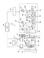
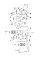
つぎにこの発明を図に示す具体例に基づいて説明する。先ず、この発明で対象とする動力伝達装置について説明すると、図3は、この発明の一実施例である制御装置が適用されるハイブリッド車用の動力伝達装置10を説明するスケルトン図である。図3において、この動力伝達装置10は、車体に取り付けられる非回転部材としてのトランスミッションケース12(以下、ケース12という)内において共通の軸心上に配設された入力回転部材としての入力軸14と、この入力軸14に直接にあるいは図示しない脈動吸収ダンパー(振動減衰装置)などを介して間接に連結された電気的な無段変速部11と、その無段変速部11と駆動輪(図示せず)との間の動力伝達経路で伝達部材(伝動軸)18を介して直列に連結されている有段式の変速機として機能する機械的変速部20と、この機械的変速部20に連結されている出力回転部材としての出力軸22とを直列に備えている。この動力伝達装置10は、例えば車両において縦置きされるFR(フロントエンジン・リヤドライブ)型車両に好適に用いられるものであり、入力軸14に直接にあるいは図示しない脈動吸収ダンパーを介して直接的に連結された走行用の駆動力源として例えばガソリンエンジンやディーゼルエンジン等の内燃機関であるエンジン8と一対の駆動輪(図示せず)との間に設けられている。なお、動力伝達装置10はその軸心に対して対称的に構成されているため、図3のスケルトン図においてはその下側が省略されている。以下の各実施例についても同様である。 Next, the present invention will be described based on a specific example shown in the drawings. First, a power transmission device targeted by the present invention will be described. FIG. 3 is a skeleton diagram illustrating a
無段変速部11は、第1電動機M1と、入力軸14に入力されたエンジン8の出力を機械的に分配する機械的機構であってエンジン8の出力を第1電動機M1および伝達部材18に分配する差動機構としての動力分配機構16と、伝達部材18と一体的に回転するように設けられている第2電動機M2とを備えている。なお、この第2電動機M2は伝達部材18から駆動輪までの間の動力伝達経路を構成するいずれの部分に設けられてもよい。本実施例の第1電動機M1および第2電動機M2は発電機能をも有するいわゆるモータジェネレータであるが、第1電動機M1は反力を発生させるためのジェネレータ(発電)機能を少なくとも備え、第2電動機M2は走行用の駆動力源として駆動力を出力するためのモータ(電動機)機能を少なくとも備える。 The continuously
動力分配機構16は、例えば「0.418」程度の所定のギヤ比ρ1を有するシングルピニオン型の第1遊星歯車装置24を主体として構成されている。この第1遊星歯車装置24は、第1サンギヤS1、第1遊星歯車P1、その第1遊星歯車P1を自転および公転可能に支持する第1キャリヤCA1、第1遊星歯車P1を介して第1サンギヤS1と噛み合う第1リングギヤR1を回転要素(要素)として備えている。第1サンギヤS1の歯数をZS1、第1リングギヤR1の歯数をZR1とすると、上記ギヤ比ρ1はZS1/ZR1である。 The
この動力分配機構16においては、第1キャリヤCA1は入力軸14すなわちエンジン8に連結され、第1サンギヤS1は第1電動機M1に連結され、第1リングギヤR1は伝達部材18に連結されている。また、動力分配機構16は第1遊星歯車装置24の3要素である第1サンギヤS1、第1キャリヤCA1、第1リングギヤR1がそれぞれ相互に相対回転可能とされて差動作用が作動可能なすなわち差動作用が働く差動状態とされることから、エンジン8の出力が第1電動機M1と伝達部材18とに分配されるとともに、分配されたエンジン8の出力の一部で第1電動機M1から発生させられた電気エネルギで蓄電されたり第2電動機M2が回転駆動されるので、無段変速部11(動力分配機構16)は電気的な差動装置として機能させられて例えば無段変速部11はいわゆる無段変速状態(電気的CVT状態)とされて、エンジン8の所定回転に拘わらず伝達部材18の回転が連続的に変化させられる。すなわち、動力分配機構16が差動状態とされると無段変速部11も差動状態とされ、無段変速部11はその変速比Y0(入力軸14の回転速度/伝達部材18の回転速度)が最小値Y0minから最大値Y0maxまで連続的に変化させられる電気的な無段変速機として機能する無段変速状態とされる。 In the
さらに、無段変速部11は、ハイ・ローの二段に切り替わる有段的な変速機構として機能するように構成されている。すなわち、第1サンギヤS1と第1キャリヤCA1との間に直結クラッチC0が設けられ、また第1サンギヤS1を選択的に固定する増速ブレーキB0が設けられている。したがって、直結クラッチC0が係合することにより、無段変速部11を構成している第1遊星歯車装置24の全体が一体となって回転するので、エンジン8から入力された動力をそのまま伝達部材18に出力するようになっている。すなわち、ロー状態である。また、直結クラッチC0に替えて増速ブレーキB0を係合させることにより、第1サンギヤS1が固定要素となり、かつ第1キャリヤCA1が入力要素となるので、第1リングギヤR1およびこれと一体の伝達部材18が、入力回転数であるエンジン回転数(第1キャリヤCA1の回転数)に対して増速されて回転する。すなわち、ハイ状態である。 Furthermore, the continuously
機械的変速部20は、シングルピニオン型の第2遊星歯車装置26、シングルピニオン型の第3遊星歯車装置28、およびシングルピニオン型の第4遊星歯車装置30を備えている。第2遊星歯車装置26は、第2サンギヤS2、第2遊星歯車P2、その第2遊星歯車P2を自転および公転可能に支持する第2キャリヤCA2、第2遊星歯車P2を介して第2サンギヤS2と噛み合う第2リングギヤR2を備えており、例えば「0.562」程度の所定のギヤ比ρ2を有している。第3遊星歯車装置28は、第3サンギヤS3、第3遊星歯車P3、その第3遊星歯車P3を自転および公転可能に支持する第3キャリヤCA3、第3遊星歯車P3を介して第3サンギヤS3と噛み合う第3リングギヤR3を備えており、例えば「0.425」程度の所定のギヤ比ρ3を有している。第4遊星歯車装置30は、第4サンギヤS4、第4遊星歯車P4、その第4遊星歯車P4を自転および公転可能に支持する第4キャリヤCA4、第4遊星歯車P4を介して第4サンギヤS4と噛み合う第4リングギヤR4を備えており、例えば「0.421」程度の所定のギヤ比ρ4を有している。第2サンギヤS2の歯数をZS2、第2リングギヤR2の歯数をZR2、第3サンギヤS3の歯数をZS3、第3リングギヤR3の歯数をZR3、第4サンギヤS4の歯数をZS4、第4リングギヤR4の歯数をZR4とすると、上記ギヤ比ρ2はZS2/ZR2、上記ギヤ比ρ3はZS3/ZR3、上記ギヤ比ρ4はZS4/ZR4である。 The
機械的変速部20では、第2サンギヤS2と第3サンギヤS3とが一体的に連結されて第2クラッチC2を介して伝達部材18に選択的に連結されるとともに第1ブレーキB1を介してケース12に選択的に連結され、第2キャリヤCA2は第2ブレーキB2を介してケース12に選択的に連結され、第4リングギヤR4は第3ブレーキB3を介してケース12に選択的に連結され、第2リングギヤR2と第3キャリヤCA3と第4キャリヤCA4とが一体的に連結されて出力軸22に連結され、第3リングギヤR3と第4サンギヤS4とが一体的に連結されて第1クラッチC1を介して伝達部材18に選択的に連結されている。 In the
前記直結クラッチC0、第1クラッチC1、第2クラッチC2、増速ブレーキB0、第1ブレーキB1、第2ブレーキB2、および第3ブレーキB3は従来の車両用自動変速機においてよく用いられている油圧式摩擦係合装置であって、互いに重ねられた複数枚の摩擦板が油圧アクチュエータにより押圧される湿式多板型や、回転するドラムの外周面に巻き付けられた1本または2本のバンドの一端が油圧アクチュエータによって引き締められるバンドブレーキなどにより構成され、それが介挿されている両側の部材を選択的に連結するためのものである。なお、これらの直結クラッチC0、第1クラッチC1、第2クラッチC2、増速ブレーキB0、第1ブレーキB1、第2ブレーキB2、および第3ブレーキB3が、この発明のトルク断続機構に相当する。 The direct coupling clutch C0, the first clutch C1, the second clutch C2, the speed increasing brake B0, the first brake B1, the second brake B2, and the third brake B3 are hydraulic pressures often used in conventional automatic transmissions for vehicles. One type of friction engagement device, a wet multi-plate type in which a plurality of friction plates stacked on each other are pressed by a hydraulic actuator, or one end of one or two bands wound around the outer peripheral surface of a rotating drum Is composed of a band brake or the like that is tightened by a hydraulic actuator, for selectively connecting the members on both sides of the band brake. The direct coupling clutch C0, the first clutch C1, the second clutch C2, the speed increasing brake B0, the first brake B1, the second brake B2, and the third brake B3 correspond to the torque interrupting mechanism of the present invention.
以上のように構成された動力伝達装置10では、例えば、図4の係合作動表に示されるように、前記直結クラッチC0、第1クラッチC1、第2クラッチC2、増速ブレーキB0、第1ブレーキB1、第2ブレーキB2、および第3ブレーキB3が選択的に係合作動させられることにより、第1速ギヤ段(第1変速段:1st)ないし第5速ギヤ段(第5変速段:5th)のいずれかあるいは後進ギヤ段(後進変速段:R)あるいはニュートラル(N)が選択的に成立させられ、ほぼ等比的に変化する変速比Y(=入力軸回転速度NIN/出力軸回転速度N0UT)が各ギヤ段毎に得られるようになっている。特に、前記直結クラッチC0および増速ブレーキB0を解放して無段変速部11を無段変速機構として機能させることにより、無段変速部11と機械的変速部20とで無段変速状態となる。 In the
例えば、直結クラッチC0もしくは増速ブレーキB0を係合させて無段変速部11の変速比を一定値に固定して動力伝達装置10が有段変速機として機能する場合について説明すると、図4に示すように、直結クラッチC0ならびに第1クラッチC1および第3ブレーキB3の係合により第1速ギヤ段が成立させられ、直結クラッチC0ならびに第1クラッチC1および第2ブレーキB2の係合により第2速ギヤ段が成立させられ、直結クラッチC0ならびに第1クラッチC1および第1ブレーキB1の係合により第3速ギヤ段が成立させられ、直結クラッチC0ならびに第1クラッチC1および第2クラッチC2の係合により第4速ギヤ段が成立させられ、第1クラッチC1および第2クラッチC2ならびに増速ブレーキB0の係合により第5速ギヤ段が成立させられる。また、第2クラッチC2および第3ブレーキB3の係合により後進ギヤ段が成立させられる。なお、ニュートラル「N」状態とする場合には、全ての係合機構が解放させられる。 For example, a case where the
一方、動力伝達装置10が無段変速機として機能する場合には、直結クラッチC0および増速ブレーキB0を解放して無段変速部11が無段変速機として機能し、それに直列の機械的変速部20が有段変速機として機能することにより、機械的変速部20の第1速、第2速、第3速、第4速の各ギヤ段に対しその機械的変速部20に入力される回転速度すなわち伝達部材18の回転速度が無段的に変化させられて各ギヤ段は無段的な変速比幅が得られる。したがって、その各ギヤ段の間が無段的に連続変化可能な変速比となって、無段変速部11と機械的変速部20とで形成される変速比YT、すなわち無段変速部11の変速比Y0と機械的変速部20の変速比Yとに基づいて形成される動力伝達装置10全体としての変速比YTである総合変速比(以下、トータル変速比という)YTが無段階に得られるようになる。 On the other hand, when the
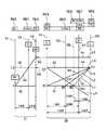
図5は、差動部あるいは第1変速部として機能する無段変速部11と変速部(自動変速部)あるいは第2変速部として機能する機械的変速部20とから構成される動力伝達装置10において、ギヤ段毎に連結状態が異なる各回転要素の回転速度の相対関係を直線上で表すことができる共線図を示している。この図5の共線図は、各遊星歯車装置24,26,28,30のギヤ比ρの関係を示す横軸と、相対的回転速度を示す縦軸とから成る二次元座標であり、3本の横線のうちの下側の横線X1が回転速度零を示し、上側の横線X2が回転速度「1.0」すなわち入力軸14に連結されたエンジン8の回転速度Neを示し、横線XGが伝達部材18の回転速度を示している。 FIG. 5 shows a
また、無段変速部11を構成する動力分配機構16の3つの要素に対応する3本の縦線Y1,Y2,Y3は、左側から順に第2回転要素(第2要素)RE2に対応する第1サンギヤS1、第1回転要素(第1要素)RE1に対応する第1キャリヤCA1、第3回転要素(第3要素)RE3に対応する第1リングギヤR1の相対回転速度を示すものであり、それらの間隔は第1遊星歯車装置24のギヤ比ρ1に応じて定められている。さらに、機械的変速部20の5本の縦線Y4,Y5,Y6,Y7,Y8は、左から順に、第4回転要素(第4要素)RE4に対応しかつ相互に連結された第2サンギヤS2および第3サンギヤS3を、第5回転要素(第5要素)RE5に対応する第2キャリヤCA2を、第6回転要素(第6要素)RE6に対応する第4リングギヤR4を、第7回転要素(第7要素)RE7に対応しかつ相互に連結された第2リングギヤR2、第3キャリヤCA3、第4キャリヤCA4を、第8回転要素(第8要素)RE8に対応しかつ相互に連結された第3リングギヤR3、第4サンギヤS4をそれぞれ表し、それらの間隔は第2、第3、第4遊星歯車装置26,28,30のギヤ比ρ2,ρ3,ρ4に応じてそれぞれ定められている。共線図の縦軸間の関係においてサンギヤとキャリヤとの間が「1」に対応する間隔とされるとキャリヤとリングギヤとの間が遊星歯車装置のギヤ比ρに対応する間隔とされる。すなわち、無段変速部11では縦線Y1とY2との縦線間が「1」に対応する間隔に設定され、縦線Y2とY3との間隔はギヤ比ρ1に対応する間隔に設定される。また、機械的変速部20では各第2、第3、第4遊星歯車装置26,28,30毎にそのサンギヤとキャリヤとの間が「1」に対応する間隔に設定され、キャリヤとリングギヤとの間がρに対応する間隔に設定される。 Further, three vertical lines Y1, Y2, Y3 corresponding to the three elements of the
上記図5の共線図を用いて表現すれば、本実施例の動力伝達装置10は、動力分配機構16(無段変速部11)において、第1遊星歯車装置24の第1回転要素RE1(第1キャリヤCA1)が入力軸14すなわちエンジン8に連結され、第2回転要素RE2が第1電動機M1に連結され、第3回転要素(第1リングギヤR1)RE3が伝達部材18および第2電動機M2に連結されて、入力軸14の回転を伝達部材18を介して機械的変速部20へ伝達する(入力させる)ように構成されている。このとき、Y2とX2の交点を通る斜めの直線L0により第1サンギヤS1の回転速度と第1リングギヤR1の回転速度との関係が示される。 If expressed using the collinear diagram of FIG. 5 described above, the
また、第1電動機M1の発電による反力を制御することによって直線L0と縦線Y1との交点で示される第1サンギヤS1の回転が上昇あるいは下降させられると、直線L0と縦線Y3との交点で示される第1リングギヤR1の回転速度が下降あるいは上昇させられる。 When the rotation of the first sun gear S1 indicated by the intersection of the straight line L0 and the vertical line Y1 is raised or lowered by controlling the reaction force generated by the power generation of the first electric motor M1, the straight line L0 and the vertical line Y3 The rotational speed of the first ring gear R1 indicated by the intersection is lowered or raised.
また、機械的変速部20において第4回転要素RE4は第2クラッチC2を介して伝達部材18に選択的に連結されるとともに第1ブレーキB1を介してケース12に選択的に連結され、第5回転要素RE5は第2ブレーキB2を介してケース12に選択的に連結され、第6回転要素RE6は第3ブレーキB3を介してケース12に選択的に連結され、第7回転要素RE7は出力軸22に連結され、第8回転要素RE8は第1クラッチC1を介して伝達部材18に選択的に連結されている。 Further, in the
機械的変速部20では、図5に示すように、第1クラッチC1と第3ブレーキB3とが係合させられることにより、第8回転要素RE8の回転速度を示す縦線Y8と横線X2との交点と第6回転要素RE6の回転速度を示す縦線Y6と横線X1との交点とを通る斜めの直線L1と、出力軸22と連結された第7回転要素RE7の回転速度を示す縦線Y7との交点で第1速の出力軸22の回転速度が示される。同様に、第1クラッチC1と第2ブレーキB2とが係合させられることにより決まる斜めの直線L2と出力軸22と連結された第7回転要素RE7の回転速度を示す縦線Y7との交点で第2速の出力軸22の回転速度が示され、第1クラッチC1と第1ブレーキB1とが係合させられることにより決まる斜めの直線L3と出力軸22と連結された第7回転要素RE7の回転速度を示す縦線Y7との交点で第3速の出力軸22の回転速度が示され、第1クラッチC1と第2クラッチC2とが係合させられることにより決まる水平な直線L4と出力軸22と連結された第7回転要素RE7の回転速度を示す縦線Y7との交点で第4速の出力軸22の回転速度が示される。上記第1速ないし第4速では、第1電動機M1の回転数を制御することにより、エンジン回転速度NEと同じ回転速度で第8回転要素RE8に無段変速部11すなわち動力分配機構16からの動力が入力される。これに対して、第1電動機M1の回転を止めて第1サンギヤS1を固定した場合には、無段変速部11からの動力がエンジン回転速度NEよりも高い回転速度で入力されることから、第1クラッチC1および第2クラッチC2が係合させられることにより決まる水平な直線L5と出力軸22と連結された第7回転要素RE7の回転速度を示す縦線Y7との交点で第5速の出力軸22の回転速度が示される。 In the
上記の第1電動機M1を制御するための第1コントローラ31と、第2電動機M2を制御するための第2コントローラ32とが設けられている。これらのコントローラ31,32は、例えばインバータを主体として構成され、それぞれに対応する電動機M1,M2とを電動機として機能させ、あるいは発電機として機能させるように制御し、併せてそれぞれの場合における回転数やトルクを制御するように構成されている。また、各電動機M1,M2は、各コントローラ31,32を介して蓄電装置33に接続されている。この蓄電装置33は、各電動機M1,M2に電力を供給し、また各電動機M1,M2が発電機として機能した場合に、その電力を充電して蓄える装置であって、二次電池(バッテリ)およびキャパシタから構成されている。 A
一方、前記各クラッチやブレーキの係合圧や解放圧を制御するための油圧制御装置34が設けられている。この油圧制御装置34は、オイルポンプ(図示せず)で発生した油圧をライン圧に調圧するとともに、そのライン圧を元圧として各摩擦係合装置の係合圧を制御し、あるいは摩擦係合装置を解放させる際の解放圧を制御するように構成されており、具体的には従来の自動変速機で使用されている油圧制御装置を採用することができる。 On the other hand, a
そして、前記各コントローラ31,32や油圧制御装置34を電気信号によって制御することにより動力伝達装置10の全体を制御するための電子制御装置(ECU)40が設けられている。図6は、その電子制御装置40に入力される信号およびその電子制御装置40から出力される信号を例示している。この電子制御装置40は、CPU,R0M,RAM、および入出カインターフェースなどから成るいわゆるマイクロコンピュータを含んで構成されており、RAMの一時記憶機能を利用しつつR0Mに予め記憶されたプログラムに従って信号処理を行うことによりエンジン8、第1、第2電動機M1,M2に関するハイブリッド駆動制御、機械的変速部20の変速制御等の駆動制御を実行するものである。 An electronic control unit (ECU) 40 is provided for controlling the whole of the
電子制御装置40には、図6に示すような各センサやスイッチなどから、エンジン水温を示す信号、シフトポジションを表す信号、エンジン8の回転速度であるエンジン回転速度Neを表す信号、ギヤ比列設定値を示す信号、M(モータ走行)モードを指含する信号、エアコンの作動を示すエアコン信号、出力軸22の回転速度N0UTに対応する車速を表す信号、機械的変速部20の作動油温(AT油温)を示す油温信号、サイドブレーキ操作を示す信号、フットブレーキ操作を示す信号、触媒温度を示す触媒温度信号、運転者の出力要求量に対応するアクセルペダルの操作量を示すアクセル開度信号、カム角信号、スノーモード設定を示すスノーモード設定信号、車両の前後加速度を示す加速度信号、オートクルーズ走行を示すオートクルーズ信号、車両の重量を示す車重信号、各車輸の車輪速を示す車輸速信号、第1電動機M1の回転速度を表す信号、第2電動機M2の回転速度を表す信号などが、それぞれ入力される。 The
また、上記電子制御装置40からは、電子スロットル弁の開度を操作するスロットルアクチュエータヘの駆動信号、燃料噴射装置によるエンジン8への燃料供給量を制御する燃料供給量信号、過給圧を調整するための過給圧調整信号、電動エアコンを作動させるための電動エアコン駆動信号、点火装置によるエンジン8の点火時期を指令する点火信号、電動機M1,M2の作動を指令する各コントローラへの指令信号、シフトインジケータを作動させるためのシフトポジション(操作位置)表示信号、ギヤ比を表示させるためのギヤ比表示信号、スノーモードであることを表示させるためのスノーモード表示信号、制動時の車輸のスリップを防止するABSアクチュエータを作動させるためのABS作動信号、Mモードが選択されていることを表示させるMモード表示信号、機械的変速部20の油圧式摩擦係合装置の油圧アクチュエータを制御するために油圧制御装置34に含まれる電磁弁を作動させるバルブ指令信号、この油圧制御装置34の油圧源である電動油圧ポンプを作動させるための駆動指令信号、電動ヒータを駆動するための信号、クルーズコントロール制御用コンピュータヘの信号等が、それぞれ出力される。 Further, the
図7は、機械的変速部20の変速制御で使用される変速線図を示しており、車速を横軸にとり、要求出力を縦軸にとって、これら車速および要求出力をパラメータとして変速段領域が定められている。図7における実線は、アップシフト線を示し、アップシフトする際の各変速段領域の境界となっている。また、図7における破線は、ダウンシフト線を示し、ダウンシフトする際の各変速段領域の境界となっている。 FIG. 7 shows a shift diagram used in the shift control of the
これらの変速段の全ては、ドライブレンジ(ドライブポジション)が選択されている場合に設定可能であるが、手動変速モード(マニュアルモード)では高速側の変速段が制限されるようになっている。図8は上記の電子制御装置40に対してシフトポジション信号を出力するシフト装置42におけるシフトポジションの配列を示しており、車両を停止状態に維持するパーキング(P)、後進段(R:リバース)、ニュートラル(N)、ドライブ(D)の各ポジションがほぼ直線的に配列されている。この配列方向は、例えば車両の前後方向に沿う方向である。そのドライブポジションに対して車両の幅方向で隣接する位置にマニュアルポジション(M)が設けられ、そのマニュアルポジションを挟んで車両の前後方向での両側にアップシフトポジション(+)とダウンシフトポジション(−)とが設けられている。これらの各シフトポジションは、シフトレバー43を案内するガイド溝44によって連結されており、したがってシフトレバー43をガイド溝44に沿って移動させることにより適宜のシフトポジションが選択され、その選択されたシフトポジション信号が電子制御装置40に入力されるようになっている。 All of these shift speeds can be set when the drive range (drive position) is selected, but in the manual shift mode (manual mode), the shift speed on the high speed side is limited. FIG. 8 shows an arrangement of shift positions in the
そして、ドライブポジションが選択された場合には、機械的変速部20での第1速から第5速の全ての前進段が走行状態に応じて設定されるようになっている。これに対して、ドライブポジションからマニュアルポジションにシフトレバー43を移動させた状態ではドライブポジションが維持され、第5速までの変速が可能であるが、この状態から1回ダウンシフトポジションにシフトレバー43を移動する都度、ダウンシフト信号(ダウンレンジ信号)が出力され、第5速が禁止された4レンジ、第4速以上が禁止された3レンジ、第3速以上が禁止された3レンジ、第1速に固定されるLレンジに切り替えられるようになっている。なお、アップシフトポジションを選択する都度、アップシフト信号(アップレンジ信号)が出力されて、順次、高速側のレンジに切り替えられるようになっている。 When the drive position is selected, all the forward speeds from the first speed to the fifth speed in the
上記の動力伝達装置10を搭載した車両が走行する場合、例えば路面の凹凸などにより駆動輪から周期的に変動するトルクが入力される。その周波数が動力伝達装置10もしくは車両に固有の共振周波数に一致すると共振が生じて振動や騒音が大きくなる。このような共振を防止もしくは抑制するために、この発明の制御装置は、図1に示す制御を実行するように構成されている。 When the vehicle on which the
先ず、共振が発生しているか否か、もしくは共振の発生が予測されているか否かが判断される(ステップS1)。ここで想定している共振は、駆動輪側から入力されるトルクに起因する共振であり、したがって車両をベンチテストするなどのことによって共振の生じる車速などの運転状態を計測しておくことができ、その計測データに基づいて共振を検出し、もしくは予測することができる。なお、共振状態は、トルクや回転数の変動から直接検出してもよい。このステップS1で否定的に判断された場合は、共振の可能性がないので、特に制御を行うことなくリターンする。 First, it is determined whether or not resonance has occurred, or whether or not resonance has been predicted (step S1). The resonance assumed here is a resonance caused by the torque input from the drive wheel side. Therefore, it is possible to measure a driving state such as a vehicle speed at which the resonance occurs by performing a bench test of the vehicle. The resonance can be detected or predicted based on the measurement data. Note that the resonance state may be directly detected from fluctuations in torque and rotational speed. If a negative determination is made in step S1, there is no possibility of resonance, and the process returns without performing any particular control.
これに対してステップS1で肯定的に判断された場合には、動力分配機構16(無段変速部11)における直結クラッチC0あるいは増速ブレーキB0を解放側に制御する(ステップS2)。すなわち、完全に係合している場合には、半係合状態もしくは解放状態に制御し、そのトルク容量を低下させる。この制御の第1の目的は、エンジン8と機械的変速部20とがロー状態もしくはハイ状態で直結されていたのを、第1電動機M1でトルクを付加し、もしくはトルクを吸収できる状態とすることにより、エンジン8と駆動輪との間のトルクの伝達状態もしくはその振動系の実質的な質量を変化させて共振を抑制もしくは解消することにあり、また第2の目的は、第1電動機M1を制御してエンジン8の運転点を変更できるようにすることにある。 On the other hand, if a positive determination is made in step S1, the direct coupling clutch C0 or the acceleration brake B0 in the power distribution mechanism 16 (the continuously variable transmission unit 11) is controlled to the disengagement side (step S2). That is, when it is completely engaged, the torque capacity is reduced by controlling the half-engaged state or the released state. The first purpose of this control is that the
つぎに、車両が駆動状態にあるか否かが判断される(ステップS3)。共振周波数には、振動系の質量や弾性係数などが関係するので、質量を変化させれば、共振周波数が変化して共振を抑制もしくは回避できる。したがって上述した動力伝達装置10では、エンジン8から駆動輪に到る動力伝達系統に介在するクラッチやブレーキなどのトルク断続機構のトルク容量を低下することにより、振動系の実質的な質量を低下させれば、共振を抑制もしくは回避できる。しかしながら、トルク断続機構のトルク容量を低下させると、エンジン8側から駆動輪に与えるトルクが低下するので、走行状態に影響が生じる可能性がある。その影響は、被駆動状態よりも駆動状態において大きいので、共振抑制制御の内容を選択するに先立ってステップS3で車両が駆動状態にあるか被駆動状態にあるかを判断することとしたのである。 Next, it is determined whether or not the vehicle is in a driving state (step S3). Since the resonance frequency is related to the mass of the vibration system, the elastic coefficient, and the like, if the mass is changed, the resonance frequency can be changed to suppress or avoid the resonance. Therefore, in the
車両が駆動状態となっていてステップS3で肯定的に判断された場合、駆動輪での駆動トルクを可及的に変化させない共振抑制制御が選択される。そのために、先ず、変速比を変更することにより対応可能か否かが判断される(ステップS4)。ここで変更の可否を判断される変速比は、上述した無段変速部11の変速比(入出力回転数比)と機械的変速部20の変速比(入出力回転数比)とである。ステップS4では、車両の全体として変速比が可及的に変化しないように、各変速比を変更した場合の共振の抑制の可能性が判断される。 If the vehicle is in a driving state and an affirmative determination is made in step S3, resonance suppression control that does not change the driving torque on the driving wheels as much as possible is selected. For this purpose, first, it is determined whether or not the change can be made by changing the gear ratio (step S4). Here, the gear ratios that are determined to be changeable are the gear ratio of the continuously variable transmission unit 11 (input / output rotational speed ratio) and the gear ratio of the mechanical transmission unit 20 (input / output rotational speed ratio). In step S4, the possibility of suppression of resonance when each gear ratio is changed is determined so that the gear ratio of the vehicle as a whole does not change as much as possible.
無段変速部11の変速比を変化させると、各電動機M1,M2の回転数が変化し、また機械的変速部20の変速比を変化させれば、機械的変速部20を構成している歯車などの回転部材の回転数が変化する。そのため、例えば無段変速部11の変速比を大きくするとともに、機械的変速部20の変速比を小さくした場合、振動系の実質的な質量や振動モードなどが変化するので、共振点が変化し、その結果、共振を抑制もしくは回避できる可能性がある。そこで、各変速比の組み合わせ毎の共振点や振動モードなどを、実験あるいはシミュレーションによって求めておき、検出もしくは予測された共振の周波数に一致しない変速比の組み合わせを選択する。ステップS4では、そのような事前の実験もしくはシミュレーションなどによるデータの有無を含めて、各変速比の組み合わせの選択が可能か否かが判断される。 When the transmission ratio of the continuously
ステップS4で肯定的に判断された場合には、無段変速部11の変速比および機械的変速部20の変速比を、上記のステップS4で判断された、共振を抑制できる変速比にそれぞれ変更する(ステップS5)。したがって、このように制御した場合には、エンジン8の運転点が変更されないので、エンジン8を燃費のよい運転状態に維持し、運転者の違和感や燃費の悪化などを防止もしくは抑制することができる。また、共振による大きいトルクや荷重が動力伝達装置10に掛かることが抑制されるので、その耐久性を向上させることができ、さらには乗り心地の悪化を防止できる。 If the determination in step S4 is affirmative, the transmission gear ratio of the continuously
これに対してステップS4で否定的に判断された場合には、エンジン8の動作点が変更される(ステップS6)。これは、具体的には、前記第1電動機M1の回転数を変化させることにより、エンジン8の回転数を変化させることにより実行される。その場合、無段変速部11における出力部材に相当する伝達部材18のトルクを可及的に維持するために、第2電動機M2によってトルクを付加し、もしくはトルクを吸収する。 On the other hand, when a negative determination is made in step S4, the operating point of the
エンジン8の出力を維持したままその運転点を変化させると、その回転数および出力トルクが変化する。そのため、動力伝達装置10に対してエンジン8側から作用するトルクの周波数と駆動輪側から入力されるトルクの周波数とにズレが生じるので、共振が抑制もしくは回避され、それに伴い動力伝達装置10の耐久性の低下を防止もしくは抑制できる。 If the operating point is changed while the output of the
一方、車両が被駆動状態であることによりステップS3で否定的に判断された場合には、車両が前進走行状態になっているか否かが判断される(ステップS7)。これは、その時点でトルクの伝達に関与しているクラッチを判断するためである。したがって、前進走行していることによりステップS7で肯定的に判断された場合には、図3に示す第1クラッチC1が機械的変速部20における入力クラッチになっているので、この第1クラッチC1のトルク容量を低下させる(ステップS8)。具体的には、第1クラッチC1の係合圧を減圧する。これに対して後進走行していることによりステップS7で否定的に判断された場合には、図3に示す第2クラッチC2が機械的変速部20における入力クラッチになっているので、その係合圧を減圧してそのトルク容量を低下させる(ステップS9)。 On the other hand, when a negative determination is made in step S3 because the vehicle is in a driven state, it is determined whether or not the vehicle is in a forward traveling state (step S7). This is to determine the clutch that is currently involved in torque transmission. Therefore, if the determination in step S7 is affirmative because the vehicle is traveling forward, the first clutch C1 shown in FIG. 3 is an input clutch in the
これらのクラッチC1,C2の係合圧について説明すると、これらのクラッチC1,C2は、前進走行時あるいは後進走行時に、無段変速部11(動力分配機構16)から入力されるトルクを機械的変速部20に伝達するものであるから、その伝達するべきトルクと同等以上のトルク容量が必要である。そのトルク容量は、係合圧に応じて増減し、係合圧が大きいほどトルク容量(伝達トルク)が大きくなる。また、車両が走行している場合には、急加速や急減速による入力トルクの一時的な増大や駆動輪側から入力されるトルクの一時的な増大などが生じるので、そのような場合の滑りを回避するために、安全率を見込んだ係合圧が設定される。図2には、伝達するべきトルク(必要トルク)に対する油圧をPr1線で示し、安全率を見込んで設定される油圧をPr2線で示してある。したがって、これらの線Pr1,Pr2で示す圧力の間で係合圧を変化させても車両の走行を維持できるので、ステップS8もしくはステップS9では、例えば安全率を低下させて上記の各線Pr1,Pr2で示す油圧の間の油圧Pr3に係合圧を減圧する。 The engagement pressures of the clutches C1 and C2 will be described. These clutches C1 and C2 mechanically shift the torque input from the continuously variable transmission unit 11 (power distribution mechanism 16) during forward travel or reverse travel. Since the torque is to be transmitted to the
共振が生じた場合、その時点でトルクを伝達しているクラッチC1,C2に掛かるトルクが周期的に増大するので、上記のように係合圧を減圧してトルク容量を低下させると、クラッチC1,C2に滑りが生じて増大したトルクを伝達せずに遮断することがある。このようなトルクの伝達状態の変化によって共振が抑制もしくは回避され、その結果、乗り心地の悪化や動力伝達装置10の耐久性の悪化を防止もしくは抑制することができる。 When resonance occurs, the torque applied to the clutches C1 and C2 transmitting torque at that time increases periodically. Therefore, when the torque capacity is reduced by reducing the engagement pressure as described above, the clutch C1 , C2 may be slipped and cut off without transmitting the increased torque. Such a change in torque transmission state suppresses or avoids resonance, and as a result, it is possible to prevent or suppress deterioration in riding comfort and deterioration in durability of the
ここで上述した具体例とこの発明との関係を簡単に説明すると、図1に示すステップS1の制御を実行する機能的手段が、この発明の共振検出/予測手段に相当し、ステップS3の制御を実行する機能的手段が、この発明の運転状態検出手段に相当し、ステップS4ないしステップS9の制御を実行する機能的手段が、この発明の共振抑制制御選択手段に相当する。また一方、ステップS8およびステップS9の制御が、この発明の第1共振抑制制御に相当し、ステップS4ないしステップS6の制御が、この発明の第2共振抑制制御に相当する。また、ステップS3で否定的に判断される運転状態が、この発明における第1運転状態に相当し、ステップS3で肯定的に判断される運転状態が、この発明における第2運転状態に相当する。そして、各クラッチC0,C1,C2および各ブレーキB0,B1,B2,B3が、この発明のトルク断続機構に相当する。The relationship between the above-described specific example and the present invention will be briefly described below. The functional means for executing the control in step S1 shown in FIG. 1 corresponds to the resonance detecting / predicting means in the present invention, and the control in step S3. The functional means for executing is equivalent to the operating state detecting means of the present invention, and the functional means for executing the control in steps S4 to S9 is equivalent to the resonance suppression control selecting means of the present invention. On the other hand, the control in step S8 and step S9 corresponds to a first resonance suppression control of the present invention, control of stepsS4 to step S6 is equivalent to the second resonance suppression control of the present invention. Further, the operating state determined negatively in step S3 corresponds to the first operating state in the present invention, and the operating state determined positive in step S3 corresponds to the second operating state in the present invention. And each clutch C0, C1, C2 and each brake B0, B1, B2, B3 are equivalent to the torque interruption mechanism of this invention.
なお、この発明は上述した具体例に限定されないのであって、前述した各共振抑制制御を個別に実行せずに、いずれかを組み合わせて実行することとしてもよい。図9には、共振の予測が成立したことに伴い、エンジン回転数、クラッチ油圧、機械的変速部の変速比、ならびに無段変速部の変速比を変更する制御例についてのタイムチャートを示してある。図9において、t1時点に共振の予測が成立すると、運転点を変更してエンジン回転数を次第に低下させ、同時にその走行状態での入力クラッチに相当するクラッチの油圧を次第に低下させ、さらに無段変速部の変速比を次第に小さくする。また、機械的変速部の変速比を低下させる制御を開始し、具体的には所定のクラッチやブレーキなどの摩擦係合装置の係合圧もしくは解放圧を次第に変化させる。エンジン回転数が低下する過程で、クラッチ油圧が目標とする圧力にまで低下し(t2時点)、これと同時に、もしくは相前後して機械的変速部の変速比および無段変速部の変速比が目標とする値に低下する。 In addition, this invention is not limited to the specific example mentioned above, Comprising: It is good also as performing not combining each resonance suppression control mentioned above individually, but performing either. FIG. 9 shows a time chart for a control example in which the engine speed, the clutch hydraulic pressure, the gear ratio of the mechanical transmission unit, and the gear ratio of the continuously variable transmission unit are changed as the resonance is predicted. is there. In FIG. 9, when the prediction of resonance is established at time t1, the operating point is changed to gradually decrease the engine speed, and at the same time, the hydraulic pressure of the clutch corresponding to the input clutch in the traveling state is gradually decreased, and further continuously. The transmission gear ratio of the transmission unit is gradually reduced. In addition, control for reducing the gear ratio of the mechanical transmission unit is started, and specifically, the engagement pressure or release pressure of a friction engagement device such as a predetermined clutch or brake is gradually changed. In the process of lowering the engine speed, the clutch hydraulic pressure is reduced to the target pressure (at time t2), and at the same time or before and after, the transmission gear ratio of the mechanical transmission unit and the transmission gear ratio of the continuously variable transmission unit are changed. Decrease to the target value.
その後のt3時点に、予測された共振域に入るが、その時点では、クラッチ油圧が低下し、また各変速比が小さくなっており、しかもエンジン回転数が目標とする回転数に低下するので、共振が生じず、もしくは共振が抑制される。そして、走行状態の変化などによって共振域を脱し、あるいは共振の予測が成立しなくなると(t4時点)、運転点を元に戻すことによりエンジン回転数を次第に増大させ、その過程のt5時点にクラッチ油圧を増大させ始め、また機械的変速部および無段変速部の各変速比を元に戻す。その後のt6時点に制御が終了する。この図9に示すように制御を行っても、伝達されるトルクや回転数が変化するので、共振を防止でき、あるいは共振を抑制することができる。 After that, at the time t3, it enters the predicted resonance range, but at that time, the clutch hydraulic pressure decreases, and each gear ratio decreases, and the engine speed decreases to the target speed. Resonance does not occur or resonance is suppressed. Then, when the resonance state is removed due to a change in the running state or the prediction of resonance is not established (at time t4), the engine speed is gradually increased by returning the operating point to the clutch at time t5 in the process. The hydraulic pressure is increased, and the gear ratios of the mechanical transmission unit and the continuously variable transmission unit are restored. Thereafter, the control ends at time t6. Even if the control is performed as shown in FIG. 9, the transmitted torque and the number of revolutions change, so that resonance can be prevented or resonance can be suppressed.
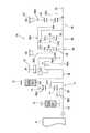
また、この発明を適用できる動力伝達機構は図3に示す構成以外の構成のものであってもよい。その例を示すと、図10は図3に示す構成における直結クラッチC0および増速ブレーキB0を省いたものである。したがって図10には、図3に示す構成と同一の部分に同一の符号を付してある。なお、図10には、図3に示す制御系統の構成は省略してある。 The power transmission mechanism to which the present invention can be applied may have a configuration other than the configuration shown in FIG. As an example, FIG. 10 is obtained by omitting the direct coupling clutch C0 and the speed increasing brake B0 in the configuration shown in FIG. Therefore, in FIG. 10, the same reference numerals are given to the same parts as those shown in FIG. In FIG. 10, the configuration of the control system shown in FIG. 3 is omitted.
図11に示す例は、図10に示す構成のうち第4遊星歯車装置30を省き、かつ第2遊星歯車装置26と第3遊星歯車装置28との配置位置を入れ替えたものである。したがって、図11には、図3および図10と同一の部分に同一の符号を付してある。さらに、図12に示す例は、図11に示す構成に、図3に示す直結クラッチC0および増速ブレーキB0を追加したものである。したがって図12には、図3および図10ならびに図11と同一の部分に同一の符号を付してある。 In the example shown in FIG. 11, the fourth
8…エンジン、 10…動力伝達装置、 11…無段変速部、 16…動力分配機構(差動機構)、 20…機械的変速部、 C0…直結クラッチ、 C1…第1クラッチ、 C2…第2クラッチ、 B0…増速ブレーキ、 M1…第1電動機、 M2…第2電動機。 DESCRIPTION OF
Claims (6)
Translated fromJapanese前記動力の伝達に伴って前記動力伝達装置に共振が発生したことを検出しもしくは共振の発生を予測する共振検出/予測手段と、
前記共振検出/予測手段によって前記共振の発生が検出もしくは予測された場合に車両の運転状態を検出する運転状態検出手段と、
前記運転状態検出手段で検出された前記車両の運転状態に基づいて、前記検出もしくは予測された共振を抑制するための制御の内容を変更する共振抑制制御選択手段と
を備え、
前記共振抑制制御選択手段は、
前記運転状態が前記動力源とは反対側からトルクが入力される被駆動状態の時には前記トルク断続機構のトルク容量を低下させる制御を含む第1共振抑制制御を選択し、かつ前記運転状態が前記動力源により出力された動力が入力される駆動状態の時には駆動輪での駆動トルクが変化しないようにする共振抑制制御である第2共振抑制制御を選択する手段を含む
ことを特徴とする車両用動力伝達装置の制御装置。In a control device for a vehicle power transmission device that includes a torque interrupting mechanism capable of changing a torque capacity, and that transmits power output from a power source,
Resonance detection / prediction means for detecting the occurrence of resonance in the power transmission device accompanying the transmission of power or predicting the occurrence of resonance;
Driving state detecting means for detecting the driving state of the vehicle when the occurrence of resonance is detected or predicted by the resonance detecting / predicting means;
Resonance suppression control selection means for changing the content of control for suppressing the detected or predicted resonance based on the driving state of the vehicle detected by the driving state detection means,
The resonance suppression control selection means includes
When the operating state is a driven state in which torque is input from the side opposite to the power source, the first resonance suppression control including control for reducing the torque capacity of the torque interrupting mechanism is selected, and the operating state is the The vehicle further includes means for selecting a second resonance suppression control that is a resonance suppression control that prevents the drive torque at the driving wheels from changing when the power output from the power source is input. Control device for power transmission device.
前記動力伝達装置は、トルク断続機構と、変速比を変更可能な変速機と、少なくとも三つの要素の間で差動作用を選択的に行う差動機構とのいずれかを含み、
前記第2共振抑制制御は、前記内燃機関の運転点を変更する制御または前記変速比を変更する制御のいずれかの制御である
ことを特徴とする請求項2または3に記載の車両用動力伝達装置の制御装置。The power source includes an internal combustion engine capable of changing an operating point determined by an output torque and a rotational speed or an operation amount corresponding to these,
The power transmission device includes any of a torque interrupting mechanism, a transmission capable of changing a gear ratio, and a differential mechanism that selectively performs a differential action between at least three elements,
4. The vehicle power transmission according to claim 2, wherein the second resonance suppression control is a control for changing an operating point of the internal combustion engine or a control for changing the speed ratio. 5. Control device for the device.
前記電気的変速部の反力要素に連結されたジェネレータと、前記電気的変速部の出力要素および前記機械的変速部の入力要素に連結されたモータとが設けられており、 A generator coupled to the reaction force element of the electrical transmission unit, a motor coupled to the output element of the electrical transmission unit and the input element of the mechanical transmission unit, and
前記動力源は、出力トルクと回転数もしくはこれらに対応する動作量で決まる運転点を変更可能な内燃機関を含み、この内燃機関と前記電気的変速部の入力要素とが連結されていることを特徴とする請求項2に記載の車両用動力伝達装置の制御装置。 The power source includes an internal combustion engine capable of changing an operating point determined by an output torque and a rotational speed or an operation amount corresponding to the output torque, and the internal combustion engine and an input element of the electric transmission unit are connected. The control device for a vehicle power transmission device according to claim 2, wherein the vehicle power transmission device is a control device.
前記第2共振抑制制御は、
前記機械的変速部の変速比を制御することにより前記共振を抑制することが可能か否かを判断する手段と、
前記機械的変速部の変速比を制御することにより前記共振を抑制することが可能と判断された場合は、前記駆動輪での駆動トルクが変化しないように前記機械的変速部の変速比を制御することにより前記共振を抑制する手段と、
前記機械的変速部の変速比を制御することにより前記共振を抑制することが不可能と判断された場合は、前記駆動輪での駆動トルクが変化しないように前記内燃機関の運転点を変更することにより前記共振を抑制する手段と
を含むことを特徴とする請求項2または3または5に記載の車両用動力伝達装置の制御装置。BeforeSL power source includes an output torque rotational speed or change an internal combustion engine capable operating point determined by the operation amount corresponding thereto,
The second resonance suppression control is
Means for determining whether or not the resonance can be suppressed by controlling a gear ratio of the mechanical transmission unit;
If it is determined that the resonance can be suppressed by controlling the transmission ratio of the mechanical transmission unit, the transmission ratio of the mechanical transmission unit is controlled so that the drive torque at the drive wheel does not change. Means for suppressing the resonance by:
If it is determined that the resonance cannot be suppressed by controlling the gear ratio of the mechanical transmission unit, the operating point of the internal combustion engine is changed so that the driving torque at the driving wheel does not change. The control device for a vehicle power transmission device according to claim2 , further comprising means for suppressing the resonance.
Priority Applications (2)
| Application Number | Priority Date | Filing Date | Title |
|---|---|---|---|
| JP2006053622AJP4525613B2 (en) | 2006-02-28 | 2006-02-28 | Control device for vehicle power transmission device |
| US11/679,552US7727112B2 (en) | 2006-02-28 | 2007-02-27 | Control system for power transmission unit of vehicle |
Applications Claiming Priority (1)
| Application Number | Priority Date | Filing Date | Title |
|---|---|---|---|
| JP2006053622AJP4525613B2 (en) | 2006-02-28 | 2006-02-28 | Control device for vehicle power transmission device |
Publications (2)
| Publication Number | Publication Date |
|---|---|
| JP2007232069A JP2007232069A (en) | 2007-09-13 |
| JP4525613B2true JP4525613B2 (en) | 2010-08-18 |
Family
ID=38444714
Family Applications (1)
| Application Number | Title | Priority Date | Filing Date |
|---|---|---|---|
| JP2006053622AExpired - Fee RelatedJP4525613B2 (en) | 2006-02-28 | 2006-02-28 | Control device for vehicle power transmission device |
Country Status (2)
| Country | Link |
|---|---|
| US (1) | US7727112B2 (en) |
| JP (1) | JP4525613B2 (en) |
Families Citing this family (49)
| Publication number | Priority date | Publication date | Assignee | Title |
|---|---|---|---|---|
| JP4293274B2 (en)* | 2005-10-26 | 2009-07-08 | トヨタ自動車株式会社 | Control device for vehicle drive device |
| GB0709636D0 (en)* | 2007-05-19 | 2007-06-27 | Valtra Inc | Rotation sensing |
| US8165737B2 (en)* | 2007-10-24 | 2012-04-24 | GM Global Technology Operations LLC | Method and system for controlling a power inverter in electric drives of vehicles with two-mode transmissions |
| US8260511B2 (en) | 2007-11-03 | 2012-09-04 | GM Global Technology Operations LLC | Method for stabilization of mode and fixed gear for a hybrid powertrain system |
| US8868252B2 (en) | 2007-11-03 | 2014-10-21 | GM Global Technology Operations LLC | Control architecture and method for two-dimensional optimization of input speed and input power including search windowing |
| US8374758B2 (en) | 2007-11-04 | 2013-02-12 | GM Global Technology Operations LLC | Method for developing a trip cost structure to understand input speed trip for a hybrid powertrain system |
| US7988594B2 (en)* | 2007-11-04 | 2011-08-02 | GM Global Technology Operations LLC | Method for load-based stabilization of mode and fixed gear operation of a hybrid powertrain system |
| US8346449B2 (en) | 2007-11-04 | 2013-01-01 | GM Global Technology Operations LLC | Method and apparatus to provide necessary output torque reserve by selection of hybrid range state and input speed for a hybrid powertrain system |
| US8396634B2 (en) | 2007-11-04 | 2013-03-12 | GM Global Technology Operations LLC | Method and apparatus for maximum and minimum output torque performance by selection of hybrid range state and input speed for a hybrid powertrain system |
| US8095282B2 (en)* | 2007-11-04 | 2012-01-10 | GM Global Technology Operations LLC | Method and apparatus for soft costing input speed and output speed in mode and fixed gear as function of system temperatures for cold and hot operation for a hybrid powertrain system |
| US8433486B2 (en)* | 2007-11-07 | 2013-04-30 | GM Global Technology Operations LLC | Method and apparatus to determine a preferred operating point for an engine of a powertrain system using an iterative search |
| US8075435B2 (en)* | 2008-08-22 | 2011-12-13 | Caterpillar Inc. | Dual mode input split compound split configuration EPPV transmission |
| JP4466772B2 (en)* | 2008-09-03 | 2010-05-26 | トヨタ自動車株式会社 | Vehicle control device |
| JP2011037331A (en)* | 2009-08-07 | 2011-02-24 | Toyota Motor Corp | Power train for vehicle |
| WO2011092856A1 (en)* | 2010-01-29 | 2011-08-04 | トヨタ自動車株式会社 | Power transmission device |
| JP5447088B2 (en)* | 2010-03-29 | 2014-03-19 | トヨタ自動車株式会社 | Power transmission control device |
| WO2012039019A1 (en)* | 2010-09-21 | 2012-03-29 | トヨタ自動車株式会社 | Vehicle control system |
| US8840516B2 (en)* | 2010-11-04 | 2014-09-23 | Toyota Jidosha Kabushiki Kaisha | Dynamic damper device |
| JP5569411B2 (en)* | 2011-01-26 | 2014-08-13 | トヨタ自動車株式会社 | Control device for vehicle drive device |
| KR101416355B1 (en)* | 2011-12-09 | 2014-07-09 | 현대자동차 주식회사 | Method for controlling torque of engine |
| JPWO2013088501A1 (en)* | 2011-12-12 | 2015-04-27 | トヨタ自動車株式会社 | Drive control apparatus for hybrid vehicle |
| US9421858B2 (en) | 2011-12-12 | 2016-08-23 | Toyota Jidosha Kabushiki Kaisha | Drive control device for hybrid vehicle |
| US9168911B2 (en)* | 2011-12-19 | 2015-10-27 | Toyota Jidosha Kabushiki Kaisha | Drive control device for hybrid vehicle |
| US9309965B2 (en) | 2012-02-22 | 2016-04-12 | Toyota Jidosha Kabushiki Kaisha | Device for controlling power transmission apparatus |
| DE102012204477B4 (en)* | 2012-03-21 | 2023-05-11 | Zf Friedrichshafen Ag | Transmission device with at least one electric variator for steplessly varying a transmission ratio and with power splitting |
| WO2013145090A1 (en)* | 2012-03-26 | 2013-10-03 | トヨタ自動車株式会社 | Drive control device for hybrid vehicle |
| JPWO2013145090A1 (en)* | 2012-03-26 | 2015-08-03 | トヨタ自動車株式会社 | Drive control apparatus for hybrid vehicle |
| JP6037638B2 (en)* | 2012-03-30 | 2016-12-07 | 株式会社デンソー | Driving force control device |
| JP6037639B2 (en)* | 2012-03-30 | 2016-12-07 | 株式会社デンソー | Driving force control device |
| CN104853971A (en)* | 2012-12-12 | 2015-08-19 | 丰田自动车株式会社 | Control device for hybrid vehicle |
| JP6205617B2 (en)* | 2012-12-27 | 2017-10-04 | ダイハツ工業株式会社 | Control device for automatic transmission |
| JP6114563B2 (en)* | 2013-02-04 | 2017-04-12 | 本田技研工業株式会社 | Control device for continuously variable transmission |
| JP2014184804A (en)* | 2013-03-22 | 2014-10-02 | Toyota Motor Corp | Control unit of vehicular transmission system |
| KR101510341B1 (en)* | 2013-10-28 | 2015-04-08 | 현대자동차 주식회사 | Transmission system of hybrid electric vehicle |
| KR101601102B1 (en)* | 2014-07-30 | 2016-03-08 | 현대자동차주식회사 | Power transmission system of hybrid electric vehicle |
| KR101713729B1 (en)* | 2015-06-02 | 2017-03-08 | 현대자동차 주식회사 | Planetary gear train of automatic transmission for vehicles |
| KR101713726B1 (en) | 2015-06-02 | 2017-03-08 | 현대자동차 주식회사 | Planetary gear train of automatic transmission for vehicles |
| KR101713719B1 (en) | 2015-06-02 | 2017-03-08 | 현대자동차 주식회사 | Planetary gear train of automatic transmission for vehicles |
| DE102016003575A1 (en)* | 2016-03-23 | 2017-09-28 | Daimler Ag | Drive device, in particular for an electric vehicle |
| KR102383223B1 (en)* | 2016-12-12 | 2022-04-05 | 현대자동차 주식회사 | Power transmission system of hybrid electric vehicle |
| JP6790900B2 (en)* | 2017-02-17 | 2020-11-25 | スズキ株式会社 | Vehicle control device |
| KR102335351B1 (en)* | 2017-07-10 | 2021-12-03 | 현대자동차 주식회사 | Power system having two motor |
| DE102017213334A1 (en)* | 2017-08-02 | 2019-02-07 | Robert Bosch Gmbh | Transmission for a hybrid drive assembly |
| US10787071B2 (en)* | 2017-09-22 | 2020-09-29 | Ford Global Technologies, Llc | Lockup clutch for powersplit hybrid transmission |
| JP6626906B2 (en)* | 2018-01-09 | 2019-12-25 | 本田技研工業株式会社 | Vehicle drive system |
| KR102600057B1 (en)* | 2018-08-22 | 2023-11-07 | 현대자동차 주식회사 | Power transmission system of hybrid electric vehicle |
| JP7458220B2 (en)* | 2020-03-24 | 2024-03-29 | 株式会社デンソー | Vehicle control device |
| KR20230160997A (en) | 2022-05-17 | 2023-11-27 | 현대자동차주식회사 | Hybrid electric vehicle and method of shift control for the same |
| CN118991401A (en)* | 2024-03-25 | 2024-11-22 | 中国第一汽车股份有限公司 | Parallel hybrid transmission mechanism and power transmission method |
Family Cites Families (13)
| Publication number | Priority date | Publication date | Assignee | Title |
|---|---|---|---|---|
| JPS62124355A (en)* | 1985-11-25 | 1987-06-05 | Honda Motor Co Ltd | Method for controlling clutch for fluid torque converter in vehicle transmission |
| JP2861225B2 (en)* | 1990-03-26 | 1999-02-24 | 株式会社デンソー | Control device for vehicle internal combustion engine system |
| JP3277863B2 (en) | 1997-10-15 | 2002-04-22 | ダイキン工業株式会社 | Air cleaner |
| JP3719031B2 (en)* | 1999-02-26 | 2005-11-24 | 日産自動車株式会社 | Driving force control device for vehicle equipped with continuously variable transmission |
| JP4380040B2 (en)* | 2000-08-28 | 2009-12-09 | トヨタ自動車株式会社 | Four-wheel drive electric vehicle and control method thereof |
| JP4075395B2 (en)* | 2001-05-25 | 2008-04-16 | マツダ株式会社 | Control device for vehicle engine |
| US7223200B2 (en)* | 2001-10-22 | 2007-05-29 | Toyota Jidosha Kabushiki Kaisha | Hybrid-vehicle drive system and operation method with a transmission |
| JP3893938B2 (en) | 2001-10-22 | 2007-03-14 | トヨタ自動車株式会社 | Hybrid vehicle drive structure with transmission |
| ATE491900T1 (en)* | 2002-09-12 | 2011-01-15 | Schaeffler Technologies Gmbh | METHOD FOR REDUCING SHOCKING VIBRATIONS |
| US7822524B2 (en)* | 2003-12-26 | 2010-10-26 | Toyota Jidosha Kabushiki Kaisha | Vehicular drive system |
| JP4228942B2 (en) | 2004-03-10 | 2009-02-25 | トヨタ自動車株式会社 | Control device for vehicle drive device |
| JP3858904B2 (en)* | 2004-03-11 | 2006-12-20 | 日産自動車株式会社 | Engagement method of engine clutch for hybrid transmission |
| JP4192814B2 (en) | 2004-03-16 | 2008-12-10 | トヨタ自動車株式会社 | Control device for vehicle drive device |
- 2006
- 2006-02-28JPJP2006053622Apatent/JP4525613B2/ennot_activeExpired - Fee Related
- 2007
- 2007-02-27USUS11/679,552patent/US7727112B2/enactiveActive
Also Published As
| Publication number | Publication date |
|---|---|
| JP2007232069A (en) | 2007-09-13 |
| US7727112B2 (en) | 2010-06-01 |
| US20070202987A1 (en) | 2007-08-30 |
Similar Documents
| Publication | Publication Date | Title |
|---|---|---|
| JP4525613B2 (en) | Control device for vehicle power transmission device | |
| JP4998164B2 (en) | Control device for vehicle power transmission device | |
| JP4957475B2 (en) | Control device for vehicle power transmission device | |
| JP4371099B2 (en) | Power transmission control device | |
| JP4052329B2 (en) | Shift control device for automatic transmission | |
| JP4155244B2 (en) | Control device for vehicle drive device | |
| JP4063295B2 (en) | Control device for drive device for hybrid vehicle | |
| JP5445306B2 (en) | Gear position setting method for vehicle automatic transmission | |
| JP4114643B2 (en) | Control device for vehicle drive device | |
| JP2009083594A (en) | Control device for vehicle power transmission device | |
| JP2005256883A (en) | Control device for vehicle drive device | |
| JP5330669B2 (en) | Control device for vehicle power transmission device | |
| JP2010116121A (en) | Controller of vehicular power transmission | |
| WO2007049682A1 (en) | Controller of vehicle automatic transmission | |
| JP4449884B2 (en) | Power transmission control device | |
| JP2010023775A (en) | Control device for power transmission device for vehicle | |
| JP4483892B2 (en) | Control device for drive device for hybrid vehicle | |
| JP2010036705A (en) | Controller for vehicular power transmission | |
| JP5375720B2 (en) | Power transmission control device | |
| JP2011220354A (en) | Control device for power transmission device | |
| JP2009096363A (en) | Control device for vehicle power transmission device | |
| JP5397266B2 (en) | Power transmission device | |
| JP4434129B2 (en) | Transmission control device | |
| JP2009173174A (en) | Control device for vehicle power transmission device | |
| JP2009166606A (en) | Control device for vehicle drive device |
Legal Events
| Date | Code | Title | Description |
|---|---|---|---|
| A131 | Notification of reasons for refusal | Free format text:JAPANESE INTERMEDIATE CODE: A131 Effective date:20090324 | |
| A521 | Request for written amendment filed | Free format text:JAPANESE INTERMEDIATE CODE: A523 Effective date:20090522 | |
| A131 | Notification of reasons for refusal | Free format text:JAPANESE INTERMEDIATE CODE: A131 Effective date:20090609 | |
| A521 | Request for written amendment filed | Free format text:JAPANESE INTERMEDIATE CODE: A523 Effective date:20090731 | |
| A131 | Notification of reasons for refusal | Free format text:JAPANESE INTERMEDIATE CODE: A131 Effective date:20100330 | |
| A521 | Request for written amendment filed | Free format text:JAPANESE INTERMEDIATE CODE: A523 Effective date:20100416 | |
| TRDD | Decision of grant or rejection written | ||
| A01 | Written decision to grant a patent or to grant a registration (utility model) | Free format text:JAPANESE INTERMEDIATE CODE: A01 Effective date:20100511 | |
| A01 | Written decision to grant a patent or to grant a registration (utility model) | Free format text:JAPANESE INTERMEDIATE CODE: A01 | |
| A61 | First payment of annual fees (during grant procedure) | Free format text:JAPANESE INTERMEDIATE CODE: A61 Effective date:20100524 | |
| FPAY | Renewal fee payment (event date is renewal date of database) | Free format text:PAYMENT UNTIL: 20130611 Year of fee payment:3 | |
| R151 | Written notification of patent or utility model registration | Ref document number:4525613 Country of ref document:JP Free format text:JAPANESE INTERMEDIATE CODE: R151 | |
| FPAY | Renewal fee payment (event date is renewal date of database) | Free format text:PAYMENT UNTIL: 20130611 Year of fee payment:3 | |
| LAPS | Cancellation because of no payment of annual fees |