JP4525074B2 - Product identification information management system - Google Patents
Product identification information management systemDownload PDFInfo
- Publication number
- JP4525074B2 JP4525074B2JP2003428416AJP2003428416AJP4525074B2JP 4525074 B2JP4525074 B2JP 4525074B2JP 2003428416 AJP2003428416 AJP 2003428416AJP 2003428416 AJP2003428416 AJP 2003428416AJP 4525074 B2JP4525074 B2JP 4525074B2
- Authority
- JP
- Japan
- Prior art keywords
- identification information
- product
- data
- information
- processing unit
- Prior art date
- Legal status (The legal status is an assumption and is not a legal conclusion. Google has not performed a legal analysis and makes no representation as to the accuracy of the status listed.)
- Expired - Fee Related
Links
Images


Classifications
- G—PHYSICS
- G06—COMPUTING OR CALCULATING; COUNTING
- G06Q—INFORMATION AND COMMUNICATION TECHNOLOGY [ICT] SPECIALLY ADAPTED FOR ADMINISTRATIVE, COMMERCIAL, FINANCIAL, MANAGERIAL OR SUPERVISORY PURPOSES; SYSTEMS OR METHODS SPECIALLY ADAPTED FOR ADMINISTRATIVE, COMMERCIAL, FINANCIAL, MANAGERIAL OR SUPERVISORY PURPOSES, NOT OTHERWISE PROVIDED FOR
- G06Q90/00—Systems or methods specially adapted for administrative, commercial, financial, managerial or supervisory purposes, not involving significant data processing
- G—PHYSICS
- G06—COMPUTING OR CALCULATING; COUNTING
- G06Q—INFORMATION AND COMMUNICATION TECHNOLOGY [ICT] SPECIALLY ADAPTED FOR ADMINISTRATIVE, COMMERCIAL, FINANCIAL, MANAGERIAL OR SUPERVISORY PURPOSES; SYSTEMS OR METHODS SPECIALLY ADAPTED FOR ADMINISTRATIVE, COMMERCIAL, FINANCIAL, MANAGERIAL OR SUPERVISORY PURPOSES, NOT OTHERWISE PROVIDED FOR
- G06Q10/00—Administration; Management
- G06Q10/08—Logistics, e.g. warehousing, loading or distribution; Inventory or stock management
- G06Q10/087—Inventory or stock management, e.g. order filling, procurement or balancing against orders
Landscapes
- Business, Economics & Management (AREA)
- Economics (AREA)
- Engineering & Computer Science (AREA)
- Physics & Mathematics (AREA)
- General Business, Economics & Management (AREA)
- General Physics & Mathematics (AREA)
- Theoretical Computer Science (AREA)
- Entrepreneurship & Innovation (AREA)
- Finance (AREA)
- Development Economics (AREA)
- Accounting & Taxation (AREA)
- Human Resources & Organizations (AREA)
- Marketing (AREA)
- Operations Research (AREA)
- Quality & Reliability (AREA)
- Strategic Management (AREA)
- Tourism & Hospitality (AREA)
- Management, Administration, Business Operations System, And Electronic Commerce (AREA)
- Information Retrieval, Db Structures And Fs Structures Therefor (AREA)
- Cash Registers Or Receiving Machines (AREA)
Description
Translated fromJapanese本発明は、商品に添付する識別情報を管理するための商品識別情報管理システムに関する。The present invention relates to aproduct identification information management system for managing identification information attached to aproduct .
商店等で取り扱う商品の多くにはバーコードが添付されている。バーコードとは、太い棒と細い棒、太い隙間と細い隙間を組み合わせて数字や記号などを表現したもので、これを専用の入力機器としてのバーコードリーダで読み取ることで、商品の情報を取得することができる。したがって、キーボード等の手入力による入力機器を使用することなく、商品に関する情報を正確かつ迅速に入力することができる。このため、多くの商品にバーコードが添付され、活用されている。 Bar codes are attached to many products handled in stores. A bar code is a combination of a thick bar and a thin bar, and a combination of a thick gap and a narrow gap to express numbers and symbols. By reading this with a barcode reader as a dedicated input device, product information is obtained. can do. Therefore, it is possible to input information regarding the product accurately and quickly without using a manual input device such as a keyboard. For this reason, barcodes are attached to many products and used.
商品に添付されているバーコードで表わされる情報としては、たとえばJAN(Japanese Article Number)コードが代表的である。このJANコードは、日本商品番号とも呼ばれており、13桁または8桁で構成されている。ここには、国を表わした国コードと、メーカを表わしたメーカコードと、商品を特定する製品コードおよびチェック用のチェックデジットが記されている。したがって、たとえば商品にバーコードを添付することで、商品の在庫数や売上金額を直ちに把握することができるという利点がある。 A typical example of information represented by a bar code attached to a product is a JAN (Japanese Article Number) code. This JAN code is also called a Japanese product number and consists of 13 digits or 8 digits. Here, a country code representing a country, a manufacturer code representing a manufacturer, a product code for specifying a product, and a check digit for checking are written. Therefore, for example, by attaching a barcode to a product, there is an advantage that the number of products in stock and the sales amount can be immediately grasped.
しかしながら、バーコードはたとえばコード全体が13桁で構成されている場合でも、製品コードとして割り当てられる情報が5桁であるにすぎない。そこで、JANコードを読み取っただけでは、商品名やその価格といったより詳細な情報を取得することができない。このため、バーコードを商品管理に利用する場合には、これらバーコードをデータベース検索のID(Identification)すなわち識別情報として利用する方法が採用されている。これにより、バーコード自体には商品を特定するIDのみを記しておけばよいので、その桁数を減少させることができる。バーコードに記載するIDとしては、たとえば商品コード、注文番号、納品番号、図面番号、生産管理番号、作業指示番号、シリアル番号が使用される。 However, even if the barcode is composed of 13 digits as a whole, for example, the information assigned as the product code is only 5 digits. Therefore, more detailed information such as the product name and its price cannot be acquired simply by reading the JAN code. For this reason, when barcodes are used for product management, a method of using these barcodes as ID (Identification) for database search, that is, identification information, is employed. As a result, only the ID for identifying the product needs to be written in the barcode itself, and the number of digits can be reduced. For example, a product code, an order number, a delivery number, a drawing number, a production management number, a work instruction number, and a serial number are used as the ID written on the barcode.
ところで、バーコードは人がバーコードリーダを用いて商品をスキャンすることでその内容を読み取るようになっている。したがって、たとえば陳列棚に配置した後の商品の在庫チェックには不向きである。そこで、従来からRF(Radio Frequency)タグを商品に付加することが提案されてきた。 By the way, the content of the barcode is read by a person scanning a product using a barcode reader. Therefore, for example, it is not suitable for inventory checking of products after being placed on a display shelf. Therefore, it has been proposed to add an RF (Radio Frequency) tag to a product.
RFタグは電子荷札とも呼ばれており、電波でタグから発せられた情報を読み取るので、バーコードのように商品そのものにリーダを近づけてスキャンする必要がない。したがって、衣料品、食品、日用品、書籍等の各種の商品に添付することにより、商品の在庫や販売管理、トレーサビリティ、盗難防止、情報提供などの多様な機能をもたせることができる。また、既存のバーコードシステムを遥かに超える情報処理能力を備えており、データの書き換えや、追記も可能になる。 The RF tag is also called an electronic tag, and reads information emitted from the tag by radio waves. Therefore, it is not necessary to scan the product close to the product itself like a barcode. Therefore, by attaching to various products such as clothing, food, daily necessities and books, various functions such as product inventory and sales management, traceability, theft prevention, and information provision can be provided. In addition, it has an information processing capability far exceeding that of the existing barcode system, and data can be rewritten and added.
近年、このようなRFタグがIC(Integrated Circuit)チップとアンテナを組み合わせた部品として小型化され、その価格も急激に低下して大々的な普及の兆しが見えてきている。これと共に、EPC(Electronic Product Code)と呼ばれる個体レベルで識別するRFタグを商品に添付することで、商品の流通過程の管理を行おうとする提案が行われている(たとえば特許文献1参照)。 In recent years, such an RF tag has been downsized as a component combining an IC (Integrated Circuit) chip and an antenna, and the price thereof has drastically decreased, and signs of widespread use have been seen. Along with this, a proposal has been made to manage the distribution process of merchandise by attaching an RF tag called EPC (Electronic Product Code) identified at an individual level to the merchandise (see, for example, Patent Document 1).
ところで、バーコードシステムは、前記したように既に広く普及しており、その適用分野も、単に小売店等でPOS(Point Of Sale)端末を用いて販売時にレジ(レジスタ)で商品のコードを記録して販売した商品の集計を行うだけにとどまっているものではない。たとえば、それぞれのバーコードに対応した情報をデータベースに登録することで、販売された商品の会計処理に利用するといったように、バーコードを使用した商品管理についてのあらゆる工程の流れが確立している。 By the way, as described above, the bar code system is already widely used, and the application field is also simply recorded at the cash register (register) at the time of sale using a POS (Point Of Sale) terminal in a retail store or the like. It doesn't stop at just counting the products sold. For example, by registering the information corresponding to each barcode in the database, it is used for accounting processing of the sold products, and the flow of all processes for product management using barcodes has been established. .
そこで、RFタグが普及していく過程では、商品に一時的にせよバーコードとRFタグの双方が一緒に添付される形が採られることで、バーコードについて確立した既存のシステムと共存を図って、先行したシステムを利用する者の便宜を図ると共に、新たなシステムに円滑に移行できるようにすることが必要である。 Therefore, in the process of spreading RF tags, the barcode and RF tag are both attached to the product, even temporarily, to coexist with existing systems established for barcodes. Thus, it is necessary for the convenience of those who use the preceding system to be able to make a smooth transition to the new system.
ところでRFタグはバーコードよりも取り扱う情報量が大きいので、RFタグで表わされる情報としてのRFタグ情報は、バーコードで表わされる情報としてのバーコード情報を包含することができる。このように2種類の情報量に大小関係が成立している場合には、情報量の大きな識別情報体系のIDに情報量の少ない方のIDを包含させることで2種類のIDを関連付けることができる。 By the way, since the RF tag handles a larger amount of information than the barcode, the RF tag information as information represented by the RF tag can include barcode information as information represented by the barcode. When a magnitude relationship is established between the two types of information in this way, the two types of IDs can be associated by including the ID having the smaller information amount in the ID of the identification information system having the larger information amount. it can.
ところが、このような関連付けを行うと、情報量の大きな方の体系が小さな方の体系のIDを書き込んだ形になるので、その大きな方の体系のIDのタグを添付する商品は小さな方の体系のIDを書き込んだタグをすでに扱っている商品に限定されてしまう。また、それだけでなく、情報量の小さな方の体系のIDが新たに登場するような場合には、それらに対応させた形で情報量の大きな方の体系のIDのタグを作成する必要がある。すなわち、タグの製造時点で常に、情報量の小さな方の体系のIDを意識する必要があり、その製造およびIDの管理が困難になるという問題がある。 However, when such an association is made, the system with the larger amount of information becomes the form in which the ID of the smaller system is written. Therefore, the product with the ID tag of the larger system is attached to the system with the smaller one Will be limited to products that already handle the tag with the ID. In addition, when an ID of a system with a smaller amount of information newly appears, it is necessary to create an ID tag of a system with a larger amount of information corresponding to them. . That is, there is a problem that it is necessary to be aware of the ID of the system with the smaller amount of information at the time of manufacturing the tag, and the manufacture and management of the ID become difficult.
このような問題を解決するために一方の体系のIDを他方の体系のIDが包含するのではなく、一方の体系における個体の特徴を示すキーワードを代替できるキーワードとして他方の体系のIDに混入させる提案が行われている(たとえば特許文献2)。
しかしながらこの後者の提案では、他方の体系側に一方の体系側の個体の特徴を示すキーワードを代替できるキーワードとして混入するので、混入するキーワードに多少の自由度があるものの、これらのうちのいずれかがキーワードの一致検索で検出されることが必要である。したがって、この提案でも結局は一方の体系を意識したIDを作成することが必要になり、依存性を排除することができない。 However, in this latter proposal, the keyword indicating the characteristics of an individual on one system side is mixed as a keyword that can be substituted on the other system side, so the keyword to be mixed has some degree of freedom, but either Must be detected by keyword matching search. Therefore, even with this proposal, it is necessary to create an ID that is conscious of one of the systems, and the dependency cannot be excluded.
そこで本発明の目的は、一方の体系の識別情報に依存しない独立した体系の識別情報を商品に添付することができ、しかも2つの体系の間で識別情報の関連付けが可能な商品識別情報管理システムを提供することにある。Accordingly, an object of the present invention is to provide aproduct identification information management system that can attach identification information of an independent system that does not depend on identification information of one system to a product, and that can associate identification information between the twosystems. Is to provide.
本発明では、(イ)同一の商品を識別するためにそれぞれの商品に正しく添付されている2つの体系の識別情報を読み取る識別情報関連付け時読取手段と、(ロ)この識別情報関連付け時読取手段によって読み取られた前記した2つの体系の識別情報における商品の種類を識別する情報部分としてのクラスフィールドを商品の種類ごとに相互に関連付ける関連付け手段と、(ハ)この関連付け手段によってクラスフィールドを関連付けられた前記した2つの体系の識別情報のそれぞれを蓄積するデータベースと、(ニ)同一の商品に添付されている関連付けの不明な2つの体系の識別情報を検査用に読み取る検査時読取手段と、(ホ)この検査時読取手段の読み取った体系の識別情報と関連付けられる体系の識別情報を前記したデータベースから検索する検査時検索手段と、(へ)この検査時検索手段によって検索された識別情報と前記した検査時読取手段によって読み取った前記したクラスフィールドが関連付けられる体系の識別情報とが同一であるか否かを比較する識別情報比較手段と、(ト)この識別情報比較手段によって識別情報が同一であるとされたとき前記した検査時読取手段の読み取った商品に添付された関連付けの不明な2つの体系の識別情報が同一の商品の識別情報として関連付けられていると判別し、それ以外の場合には同一の商品の識別情報としては関連付けられていないと判別する関連付け有無判別手段とを商品識別情報管理システムが具備する。In the present invention , (b) an identification information association reading unit that reads identification information of two systems correctly attached to each product in order to identify the same product, and (b) an identification information association reading unit. And (c) an association means for associating the class field as an information part for identifying the type of product in the identification information of the two systems described above by each type of product, and (c) the class field can be associated by the association means. A database for storing each of the identification information of the two systems described above, and (d) an inspection reading means for reading the identification information of the two systems of unknown association attached to the same product for inspection, e)database with the identification information of the system associated with the identification information of the system read of this inspection and the reading means Et inspection when searching means for searching, whether it is identical to the identification information of the system that the classfield with the read by the inspection during reading meansdescribed above and retrieved identification information is associated with it by the (to) this test when searching means an identification information comparison means for comparing the whether, (g) the identification information comparing unit by the identification information is a byaforementioned the examined during reading means read item has been associated with unknown two attachment when the same It is determined that the identification information of the system is associated as the identification information of the same product, and in other cases, the association identification means for determining that it is not associated as the identification information of the same product A management systemis provided.
以上説明したように本発明によれば、2つの体系の識別情報を外的に連結し、その結果をデータベース化するので、一方の識別情報に他方の体系の識別情報の全部または一部を包含させる必要がない。このため、識別情報間に依存関係が必要ないので、これらを独立して管理することができ、また、識別情報自体も無駄な情報を含める必要がないので効率的な情報配置とすることができる。 As described above, according to the present invention, the identification information of two systems is externally linked and the result is made into a database, so that one identification information includes all or part of the identification information of the other system. There is no need to let them. For this reason, since there is no need for dependency between the identification information, these can be managed independently, and the identification information itself does not need to include useless information, so that the information can be arranged efficiently. .
以下実施例につき本発明を詳細に説明する。 Hereinafter, the present invention will be described in detail with reference to examples.
図1は、第1の実施例の商品識別情報管理システムの概要を表わしたものである。この商品識別情報管理システム100は、インターネットあるいはイントラネット等の通信ネットワーク101を利用して、特定の販売会社の各店舗で取り扱う商品の管理を行うようになっている。工場102は製造した商品103に、前記したメーカコードや製品コード等を表わしたバーコード104と、商品を一意に認識することのできる情報を書き込んだRFタグ105とを添付して出荷するようになっている。この商品103は適宜、倉庫106に保管された後、前記した販売会社の商品購入部門107に納入される。商品購入部門107は、この販売会社の情報管理部門108および店舗109と共に通信ネットワーク101に接続されている。ここで、工場102、倉庫106、商品購入部門107および店舗109は、1つずつしか示していないが、これに限るものではない。たとえば商品購入部門107は、商品が全国規模で購入されるような場合には、分散して配置され、それぞれの土地で製造された商品を別々に購入するものであってもよい。また、店舗109は各地に展開されていてもよい。情報管理部門108も、それぞれの商品購入部門107に直結した形で配置されていてもよいし、バックアップ等のために複数が通信ネットワーク101に接続されていてもよい。 FIG. 1 shows an outline of the product identification information management system of the first embodiment. The product identification
ところで、商品購入部門107は通信ネットワーク101に接続され各種の情報処理を行う入力側情報端末111と、この入力側情報端末111に対して商品ごとにバーコード104およびRFタグ105の読取結果を入力する入力装置112を備えている。入力側情報端末111は、パーソナルコンピュータあるいはワークステーション等からなる情報処理装置であり、図示しないCPU(中央処理装置)と、所定の制御プログラムを格納した記憶媒体を備えている。そして、入力装置112から取り込んだバーコード104の入力情報およびRFタグ105の入力情報を、後に説明するように制御プログラムによって関連付けて処理するようにしている。 By the way, the
情報管理部門108も、同様にパーソナルコンピュータ等によって構成された情報管理装置114と、この装置に接続された第1および第2のデータベース115、116とを備えている。情報管理装置114は、通信機能を持っており、通信ネットワーク101と接続されている。第1のデータベース115は、バーコード104に関連するデータベースである。第2のデータベース116は、RFタグ105に関連するデータベースである。 The
店舗109は、パーソナルコンピュータ等によって構成され、同一店舗内の情報処理を統括する店舗側処理装置117を備えている。店舗側処理装置117は、たとえばレジスタごとに配置された複数の商品情報端末118とLAN(ローカルエリアネットワーク)ケーブル等の通信手段によって接続されている。商品情報端末118もパーソナルコンピュータや簡易型の情報処理装置等によって構成されているが、その処理能力は店舗側処理装置117よりも低くてよい。商品情報端末118は、バーコードリーダ119とRFタグリーダ120の双方あるいは一方を接続している。 The
図2は、商品購入部門に備えられた入力装置で商品に関する識別情報の読み取りを行っている状態を示したものである。入力装置112は商品103のバーコード104をスキャンして光学的に読み取る図示しないバーコードリーダと、RFタグ105の発する電波を受信してその情報を読み取る図示しないRFタグリーダを内蔵している。したがって、入力装置112は、これを商品103に近づけてバーコード104を読み取ると、同時にRFタグ105に記されたRFタグ情報の読み取りも行えるようになっている。 FIG. 2 shows a state in which identification information relating to a product is being read by an input device provided in the product purchase department. The
図3は、以上の構成の商品識別情報管理システムの原理的な構成を表わしたものである。図3で図1と同一部分には同一の符号を付している。入力装置112は、図2で示したようにバーコードとRFタグを同時に読み取り、バーコード情報121とRFタグ情報122を関連付け処理部123に入力するようになっている。関連付け処理部123は、図1に示した入力側情報端末111に格納された制御プログラムの一部としての関連付けプログラムを実行することによって、2つの識別情報体系の関連付けを行う処理部である。関連付けプログラムは、図1に示す入力側情報端末111内にその制御プログラムの一部として格納されている。本明細書では、バーコード情報121を使用した識別情報体系を第1の識別情報体系とし、RFタグ情報122を使用した識別情報体系を第2の識別情報体系として説明する。 FIG. 3 shows a principle configuration of the product identification information management system having the above configuration. In FIG. 3, the same parts as those in FIG. As shown in FIG. 2, the
入力側情報端末111内の関連付け処理部123は、図1に示した通信ネットワーク101を介して、情報管理装置114内のデータ更新処理部124と接続されている。データ更新処理部124は、バーコード情報121に関する第1のデータベース115の更新を行う処理部であり、データ更新プログラムによってその処理を実行するようになっている。データ更新処理部124は、入力側情報端末111からRFタグ情報122と関連付けられたバーコード情報121が送られてくると、第1のデータベース115の更新を行うようになっている。第1のデータベース115の内容は、情報管理装置114内の第1のデータ提供プログラムによって実行される第1のデータ提供処理部126によって、情報管理部門108の外部に対して提供されることになる。第2のデータベース116の内容は、情報管理装置114内の第2のデータ提供プログラムによって実行される第2のデータ提供処理部127によって、情報管理部門108の外部に提供されることになる。 The
図4は、第1のデータベースの内容の一例を示したものである。第1のデータベース115は、“A1-1”、“A1-2”、“A1-3”、……等の商品ごとにユニークなコード情報がEPCとして割り当てられており、それぞれにバーコード“B1”、と、図1に示した工場102、倉庫106および販売会社の入力装置112での該当商品の入力日時あるいは商品の通過時刻が記されている。EPC“Ai-j”で“i”はクラスフィールドの値であり、“j”はインスタンスフィールドの値である。EPC“Bi”はバーコードを示しており、ここで“i”はその値である。FIG. 4 shows an example of the contents of the first database. In the
図1で破線で示すように工場102および倉庫106も必要に応じて通信ネットワーク101に接続することができる。これら工場102および倉庫106が図3に示した入力装置112と同様の入力装置等を備えている場合、情報管理部門108の第1および第2のデータベース115、116を販売会社と共用することができる。そして、これにより商品が工場102から販売会社の入力装置112に到達するまでの経過を正確に把握することができる。 As indicated by broken lines in FIG. 1, a
図5は、第2のデータベースの内容の一例を示したものである。第2のデータベース116には、バーコード“B1”、“B2”、“B3”、……のそれぞれに対応付けて、商品の品名とサイズが記されている。FIG. 5 shows an example of the contents of the second database. In the
図3に戻って説明を続ける。図1に示した店舗109内の店舗側処理装置117は、識別情報に関するデータを取得するためのデータ取得処理部128を備えている。データ取得処理部128は、商品情報端末118のバーコードリーダ119あるいはRFタグリーダ120が読み込んだ商品に関する情報、あるいは他の手段によって得られた同様の情報を基にして、更に情報の取得の必要がある場合、データ取得処理部128を介して、第1のデータ提供処理部126あるいは第2のデータ提供処理部127から必要な情報を取得することになる。たとえば、バーコードから商品の具体的な名前やサイズを知ることができず、これらの入手が必要な場合には、第2のデータ提供処理部127を用いて第2のデータベース116から、バーコードをキーとしてこれらの情報を取得することができる。このようなデータ取得処理部128は、店舗側処理装置117の図示しないCPUがデータ取得プログラムを実行することにより実現するようになっている。ユーザ端末としての商品情報端末118は、取得した情報を視覚的に表示する図示しないディスプレイや、取得した情報をプリントアウトするための同じく図示しないプリンタを備えていてもよい。 Returning to FIG. 3, the description will be continued. The store-
以上のような本実施例の商品識別情報管理システムの運用例を更に具体的に説明する。関連付け処理部123を中心としたバーコード情報121とRFタグ情報122の関連付け処理すなわちID関連付け処理と、データ取得処理部128を中心とした利用者によるデータ取得とに分けて説明する。 An operation example of the product identification information management system of this embodiment as described above will be described more specifically. The description will be divided into the association processing of the barcode information 121 and the RF tag information 122 centered on the
<ID関連付け処理> <ID association processing>
図3に示した入力装置112から、関連付けするEPC(RFタグ)としての“A2-1”と、バーコード“B2”とを、関連付け処理部123に入力する場合を説明する。図2に示したような入力装置112を使用すると、すでに説明したようにバーコードとRFタグの双方を並行して読み取り、第1の識別情報体系と第2の識別情報体系を関連付けることができる。このように時間的に連続して2種類の情報を読み取った場合、データ更新処理部124によるEPCとバーコードの関連付けは比較的容易である。もちろん、バーコードとRFタグをそれぞれ別々の時間に読み取る場合も、同一の商品に関するものであることを商品情報端末118の利用者の操作によって明らかにすれば、第1の識別情報体系と第2の識別情報体系を関連付けることが可能である。A case where “A2-1 ” as an EPC (RF tag) to be associated and the barcode “B2 ” are input to the
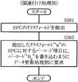
図6は、ID関連付け処理のうち関連付け処理部が行う処理の概要を表わしたものである。関連付け処理部123(図3)は、まず入力装置112を用いて読み取ったRFタグ情報から、EPCのクラスフィールドを抽出する(ステップS201)。読み取った“A2-1”におけるクラスフィールドは“2”なので、このEPCに対するバーコード項目に、バーコード“B2”を書き込むように情報管理装置114側のデータ更新処理部124に要求する(ステップS202)。FIG. 6 shows an outline of processing performed by the association processing unit in the ID association processing. The association processing unit 123 (FIG. 3) first extracts an EPC class field from the RF tag information read using the input device 112 (step S201). Since the class field in the read “A2-1 ” is “2”, the data
図7は、このステップS202の要求に対するデータ更新処理部の処理の流れを表わしたものである。データ更新処理部124は、第1のデータベース115における“EPC”項目の“A2-1”と“A2-2”に対応する“バーコード”項目に、“B2”を書き込む(ステップS221)。FIG. 7 shows the flow of processing of the data update processing unit in response to the request in step S202. The data
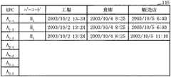
図8は、このステップS221の処理が行われた後の第1のデータベースの内容を示したものである。その直前の図4と比較すると、第1のデータベース115の“EPC”項目の“A2-1”と“A2-2”に対応する“バーコード”項目に、“B2”が新たに書き込まれている。これにより、第1のデータベース115におけるクラスの関連付けが終了する。FIG. 8 shows the contents of the first database after the processing of step S221 is performed. Compared with FIG. 4 immediately before that, “B2 ” is newlyadded to the “barcode” item corresponding to “A2-1 ” and “A2-2 ” of the “EPC” item of the
<端末利用者によるデータ取得処理> <Data acquisition process by terminal user>
図9は、端末利用者が商品に関するデータ取得を要求した際の商品情報端末の処理の流れを表わしており、図10はこれに対応する店舗側処理装置の処理の流れを表わしたものである。すなわち、個々の商品情報端末118から商品に関するデータ取得が要求されると、店舗側処理装置117はこれを仲介して図1に示す情報管理装置114をアクセスして、第1のデータ提供処理部126(図3)あるいは第2のデータ提供処理部127(図3)から必要な情報を取得することになる。 FIG. 9 shows the flow of processing of the product information terminal when the terminal user requests data acquisition related to the product, and FIG. 10 shows the flow of processing of the store side processing device corresponding to this. . That is, when data acquisition related to a product is requested from each
一例として、商品情報端末118がたとえばバーコードリーダ119(図1)のみを備えているものとする。ある商品のバーコードを読み取った結果得られるバーコード情報を基にして、端末利用者が所定のデータの参照を要求するものとする。このような場合、店舗109(図1)では、端末利用者が商品情報端末118を使用して、バーコード情報から得られるID情報と、参照したいデータ項目を指定する(ステップS241)。このような場合、CPU(中央処理装置)はたとえば参照したいデータ項目を図示しないディスプレイに選択のために表示させ、この中から所望の項目が端末利用者によって選択されるのを待機するといった処理を行う。所望の項目として、たとえば該当する商品の品名が選択されたとする。この場合、データ取得処理部128は、EPCとしての“A2-1”と、“品名”を引数として、また、戻り値をIDに対するデータ項目のデータあるいはエラー発生時のその旨の通知として、図3に示した第1のデータ提供処理部126に対してデータの取得を要求する(ステップS242)。そして、第1のデータ提供処理部126から第1のデータベース115から取得したデータが送られてくるのを待機する(ステップS243)。データが取得されれば(Y)、その結果(エラー通知も含む)を商品情報端末118のディスプレイに表示することになる(ステップS244)。As an example, it is assumed that the
図10に示す店舗側処理装置117の方では、図9のステップS242の処理による商品情報端末118から、第1のデータ提供処理部126に対するデータの取得の要求を受けると(ステップS261)、第1のデータ提供プログラムを起動して第1のデータ提供処理部126を機能させる(ステップS262)。そして、引数を第1の識別情報体系のIDと参照したいデータ項目とし、戻り値をIDに対応するデータ項目のデータあるいは第2の識別情報体系のIDあるいはエラー発生時のその旨の通知とする。 When the store
図11は、このステップS262の処理としての第1のデータ提供処理部の処理を具体的に表わしたものである。第1のデータ提供プログラムによって実現する第1のデータ提供処理部126は、まず第1の識別情報体系のIDと参照したいデータ項目を、データ取得処理部128(図3)から取得する(ステップS281)。そして、第1の識別情報体系についての第1のデータベース115を参照して、IDとデータ項目に対応するデータを検索する(ステップS282)。具体的には、図8に示す第1のデータベース115を基にして、EPCとしての“A2-1”に対する“品名”項目を検索することになる。FIG. 11 specifically shows the process of the first data provision processing unit as the process of step S262. The first data
ところが、第1のデータベース115には該当する“品名”項目そのものがない(ステップS283:N)。そこで、この場合には第1の識別情報体系の第1のデータベース115を参照して、その第1の識別情報体系のIDに対応する第2の識別情報体系のIDを検索する(ステップS284)。この例の場合には、EPCとしての“A2-1”に対する“バーコード”項目のデータとしての“B2”があったので(ステップS285:Y)、これを取得し、第1のデータ提供処理部126はこのデータ“B2”を“バーコード”項目のデータとしてデータ取得処理部128(図3)に返す(ステップS286)ことで、処理を終了させる(エンド)。However, there is no corresponding “product name” item in the first database 115 (step S283: N). Therefore, in this case, the ID of the second identification information system corresponding to the ID of the first identification information system is searched with reference to the
なお、ステップS285で、対応する第2の識別情報体系のIDが存在しなかったときには(N)、呼び出し元としてのデータ取得処理部128にエラーメッセージを返して(ステップS287)、処理を終了させる(エンド)。なお、ステップS283で“品名”項目が図8に示す第1のデータベース115に存在した場合には(Y)、呼び出し元としてのデータ取得処理部128に、これによって取得したデータを返して(ステップS288)、処理を終了させることになる(エンド)。 In step S285, when the ID of the corresponding second identification information system does not exist (N), an error message is returned to the data
図10に戻って説明を続ける。図11で説明したステップS262の処理の結果として、第1のデータ提供処理部126から、要求したデータが送られてきたら、その取得したデータが要求したデータ項目のデータであるかどうかのチェックが行われる(ステップS263)。この例では該当する商品の品名が要求されている。品名が第1のデータ提供処理部126から送られてきた場合には(Y)、これを商品情報端末118のディスプレイに表示して(ステップS264)、処理を終了する(エンド)。すなわち、図11のステップS288で取得データとしての商品の品名が得られた場合には、これをディスプレイに表示することになる。商品情報端末118に図示しないプリンタが接続されている場合には、その結果をプリントアウトしてもよい。 Returning to FIG. When the requested data is sent from the first data
これに対して、要求したデータ項目以外のデータが送られてきた場合には(ステップS263:N)、その取得したデータは第2の識別情報体系のIDであるかどうかの判別が行われる(ステップS265)。説明している例では、第1のデータベース115に該当する“品名”項目そのものがなく(図11ステップS283:N)、第1のデータ提供処理部126はデータ“B2”を“バーコード”項目のデータとしてデータ取得処理部128(図3)に返している(図11ステップS286)。したがって、取得したデータは、異なった識別情報体系としての第2の識別情報体系のIDということになる(図10ステップS265:Y)。この場合には、次のステップS266に進み、第2のデータ提供プログラムを起動して第2のデータ提供処理部127(図3)を機能させる。そして、引数を第2の識別情報体系のIDと参照したいデータ項目とし、バーコード“B2”と“品名”を引数として呼び出す。また、戻り値を、IDに対応するデータ項目のデータあるいはエラー発生時のその旨の通知とする。これについては次に説明する。これ以外の場合には(ステップS265:N)、商品の品名が分からなかったことになるので、エラーメッセージをディスプレイに表示することになる(ステップS267)。商品情報端末118に前記したようにプリンタが接続されている場合には、その結果をプリントアウトしてもよい。On the other hand, when data other than the requested data item is sent (step S263: N), it is determined whether or not the acquired data is the ID of the second identification information system ( Step S265). In the illustrated example, there is no “product name” item corresponding to the first database 115 (step S283: N in FIG. 11), and the first data
図12は、ステップS266の処理としての第2のデータ提供処理部の処理を具体的に表わしたものである。第2のデータ提供プログラムによって実現する第2のデータ提供処理部127は、まず第2の識別情報体系のIDと参照したいデータ項目を、データ取得処理部128(図3)から取得する(ステップS301)。そして、第2の識別情報体系についての第2のデータベース116を参照して、IDとデータ項目に対応するデータを検索する(ステップS302)。具体的には、図5に示す第2のデータベース116を基にして、“バーコード”としての“B2”に対する“品名”項目を検索することになる。FIG. 12 specifically shows the process of the second data provision processing unit as the process of step S266. The second data
第2のデータベース116には、該当する“品名”項目に“チョコレート”が記載されている。したがって、次のステップS303では該当するデータがあったことになり(Y)、第2のデータ提供処理部127はこのデータ“チョコレート”を、呼び出し元としてのデータ取得処理部128(図3)に返す(ステップS304)ことで、処理を終了させる(エンド)。ステップS303で該当するデータが得られなかった場合には(N)、データ取得処理部128に対してエラーメッセージを返して(ステップS305)、処理を終了させることになる(エンド)。 In the
図10に戻って説明を続ける。図12で説明したステップS266の処理の結果として、第2のデータ提供処理部127から、要求したデータが送られてきたら、その取得したデータが要求したデータ項目のデータであるかどうかのチェックが行われる(ステップS268)。この例では該当する商品の品名“チョコレート”が得られている。そこで(Y)、取得したそのデータを商品情報端末118のディスプレイに表示して(ステップS264)、処理を終了する(エンド)。すなわち商品の品名“チョコレート”をディスプレイに表示することになる。商品情報端末118に前記したプリンタが接続されている場合には、その結果をプリントアウトしてもよい。このようにしてユーザ端末としての商品情報端末118の利用者は、バーコード104から直接得られる情報以上の情報として、第2の識別情報体系で用意された第2のデータベース116の情報を取得できることになる。 Returning to FIG. When the requested data is sent from the second data
これに対して、ステップS268で、求めるデータ項目のデータが取得されなかったと判別された場合には(N)、ステップS267に進んで商品情報端末118のディスプレイにエラーメッセージを表示する。商品情報端末118に前記したプリンタが接続されている場合には、その結果をプリントアウトしてもよい。 On the other hand, if it is determined in step S268 that the data of the requested data item has not been acquired (N), the process proceeds to step S267, and an error message is displayed on the display of the
以上説明したように第1の実施例の商品識別情報管理システムでは、RFタグのIDとバーコードを関連付けるまで、それぞれのID間に依存性がない。このため、商品に添付されているバーコードとRFタグを独立して管理することができる。すなわち、EPCを書き込んでRFタグを製造するときに、バーコードを何ら意識する必要がない。 As described above, in the product identification information management system according to the first embodiment, there is no dependency between the IDs until the ID of the RF tag is associated with the barcode. For this reason, the barcode attached to the product and the RF tag can be managed independently. That is, it is not necessary to be aware of the barcode when writing the EPC to manufacture the RF tag.
図13は、第2の実施例の商品識別情報管理システムの要部について原理的な構成を表わしたものである。図13で図3と同一部分には同一の符号を付しており、これらの説明を適宜省略する。また、第2の実施例の商品識別情報管理システム400の全体的な構成は、第1の実施例の図1を適宜援用して説明する。 FIG. 13 shows the principle configuration of the main part of the product identification information management system of the second embodiment. In FIG. 13, the same parts as those in FIG. 3 are denoted by the same reference numerals, and description thereof will be omitted as appropriate. Further, the overall configuration of the product identification
入出力装置401は、バーコードとRFタグを同時に読み取る機能と、読み取った結果からEPCとバーコードのクラスの整合性をチェックして、これらが間違った対として商品に添付されている場合にその異常を知らせる報知機能とを備えている。 The input /
図14は、この入出力装置で商品の識別情報の読み取りを行っている状態を表わしたものである。入出力装置401は、その頭部に切替スイッチ402と第1および第2のインジケータ403、404および内蔵スピーカ405を配置している。切替スイッチ402は、押しボタンスイッチで、これを押し下げた状態で整合性チェックモードとなり、第1のインジケータ403が点灯するようになっている。この状態で入出力装置401はバーコードとRFタグの整合性をチェックする。切替スイッチ402が飛び出た状態では、第2のインジケータ404が点灯する。この状態では第1の実施例と同様に、バーコードとRFタグの整合性がとられているという前提の基で、両者の関連付けを行う。この後者のモードを関連付け登録モードと呼ぶことにする。内蔵スピーカ405は整合性チェックモードでEPCとバーコードのクラスの整合性がないと判定された場合に警告音を出力するためのものである。 FIG. 14 shows a state in which product identification information is being read by this input / output device. The input /
図13に戻って説明を続ける。バーコードとRFタグの読み取りによって得られたバーコード情報121とRFタグ情報122は、関連付け処理部123Aに入力されるようになっている。関連付け処理部123Aは、図1に示した入力側情報端末111に格納された制御プログラムの一部としての関連付けプログラムを実行することによって、2つの識別情報体系の関連付けを行う処理部である。関連付けプログラムは、図1に示す入力側情報端末111内にその制御プログラムの一部として格納されている。 Returning to FIG. The barcode information 121 and the RF tag information 122 obtained by reading the barcode and the RF tag are input to the
関連付け処理部123Aは、入出力装置401が整合性チェックモードになっているとき、整合性チェック処理部411と接続される。整合性チェック処理部411は、情報管理装置114内に第1のデータ提供処理部126Aと共に配置され、整合性チェックプログラムを情報管理装置114内のCPUが実行することによって実現するようになっている。第1のデータ提供処理部126Aは、第1のデータ提供プログラムを同様に情報管理装置114内のCPUが実行することによって実現する。 The
第1のデータ更新処理部124Aは、第1の実施例の場合と同様に第1のデータ更新プログラムを実行することによって実現され、第1のデータベース115の更新処理を行うようになっている。ただし、第1のデータ更新処理部124Aは、入出力装置401が関連付け登録モードになっているときにのみ動作する構成となっている。本実施例では、第1のデータベース115が図8に示す内容であるものとする。 The first data
図15は、本実施例における整合性チェックモードの処理を主として示したものである。図1に示した情報管理装置114では、入出力装置401から送られてくる切替スイッチに関する情報をチェックして、図14に示した入出力装置401が整合性チェックモードであるかどうかを判別する(ステップS451)。この結果、関連付け登録モードであると判別された場合には(N)、第1の実施例で説明したと同様の関連付け登録処理を行う(ステップS452)。 FIG. 15 mainly shows the processing of the consistency check mode in the present embodiment. The information management apparatus 114 shown in FIG. 1 checks information regarding the changeover switch sent from the input /
一方、整合性チェックモードであると判別された場合には(ステップS451:Y)、入出力装置401から送られてきたバーコード情報121とRFタグ情報(EPC)122とを対にして図示しない所定の作業用メモリ領域に格納する(ステップS453)。そして、そのEPCに対応するバーコード情報を第1のデータ提供処理部126Aを介して第1のデータベース115から取得する(ステップS454)。次に、入出力装置401から送られてきたバーコード情報121が、この取得したバーコード情報と同一の情報となっているかどうかをチェックする(ステップS455)。同一の情報となっていれば(Y)、商品103に添付されているバーコード104とRFタグ105は整合性がとれていることになる。そこでこの場合には正常であることを示す返答を入出力装置401に返すことになる(ステップS456)。入出力装置401ではそのスピーカ405から正常を示す音が出力される。 On the other hand, if it is determined that the mode is the consistency check mode (step S451: Y), the barcode information 121 and the RF tag information (EPC) 122 sent from the input /
これに対して入出力装置401で読み取ったバーコード情報121と第1のデータベース115から取得したバーコード情報とが同一のRFタグ情報に対して異なっていた場合(ステップS455:N)、情報管理装置114は異常を示す返答を該当する入出力装置401に送出する(ステップS457)。これを受け取った入出力装置401は、そのスピーカから異常を示すビープ音等の警報音を出力することになる。したがって、入出力装置401の利用者は、商品103に対にして添付しているEPCとRFタグの整合性の有無を簡単にチェックすることができる。 On the other hand, when the barcode information 121 read by the input /
図16は、第3の実施例の商品識別情報管理システムの要部について原理的な構成を表わしたものである。図16で図3と同一部分には同一の符号を付しており、これらの説明を適宜省略する。また、第3の実施例の商品識別情報管理システム500の全体的な構成は、第1の実施例の図1および図2を適宜援用して説明する。 FIG. 16 shows the principle configuration of the main part of the product identification information management system of the third embodiment. In FIG. 16, the same parts as those in FIG. 3 are denoted by the same reference numerals, and description thereof will be omitted as appropriate. Further, the overall configuration of the product identification
この商品識別情報管理システム500で入力装置112は、図2で示したようにバーコードとRFタグを同時に読み取り、バーコード情報121とRFタグ情報122を関連付け処理部123Bに入力するようになっている。本実施例の場合、入力装置112は実際には図1に示す工場102、倉庫106、商品購入部門107等に別々に設けられており、関連付け処理部123Bはそれぞれの場所を通過する時点でバーコードをキーとして第2のデータベース116を参照しながら第1のデータ更新処理部124Bによって第1のデータベース115の更新を行わせるようにしている。したがって、図1に示した商品情報端末118等のユーザ端末118Bは、時間の経過によって更新されていく第1のデータベース115から必要な情報を取得することが可能になる。ユーザ端末118Bは、その利用者が要求したデータに対する結果を表示するための図示しないディスプレイを備えている。 In the product identification
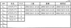
図17は、ある時点における第1のデータベースの内容を示したものである。第1のデータベース115には、“EPC”項目の“A1-1”〜“A1-3”に対応して、商品のデータ項目として“品名”と“サイズ”が記述されている。また、“工場”、“倉庫”、“販売店”の各項目には、それぞれの箇所を商品が通過した日時が記録されている。この図17に示した第1のデータベース115に対応する時点の第2のデータベース116の内容は、図5に示す通りであるものとする。FIG. 17 shows the contents of the first database at a certain point in time. In the
次に、このような構成の第3の実施例の商品識別情報管理システム500で、EPCのデータベースをバーコードのデータベースを参照して作成し、それを利用者がユーザ端末118Bを用いて参照する例を説明する。ユーザ端末118Bの利用者は、関連付けるEPCとバーコードが決定した時点で、そのバーコードに関する情報をバーコードについてのデータベースから取得し、これをEPCのデータベースの保存形式で書き込む。このような処理を、ID関連付け処理と、端末利用者によるデータ取得とに分けて説明する。 Next, in the product identification
<ID関連付け処理> <ID association processing>
図16に示した入力装置112から、関連付けするEPC(RFタグ)としての“A2-2”と、バーコード“B2”とを、関連付け処理部123Bに入力する場合を説明する。図2に示したような入力装置112を使用すると、すでに説明したようにバーコードとRFタグの双方を並行して読み取り、これらを簡単に組の情報とすることができる。その後、バーコード“B2”に対応するデータを取得するため、関連付け処理部123Bはその関連付けプログラムによって、第2のデータ提供プログラムを呼び出して、第2のデータ提供処理部127Bを機能させる。A case will be described in which “A2-2 ” and barcode “B2 ” as EPC (RF tag) to be associated are input to the association processing unit 123B from the
第2のデータ提供処理部127Bは、バーコード“B2”に対応するデータを、第2の識別情報体系の第2のデータベース116から取得するようになっている。第2のデータベース116には、図5に示す内容のデータが格納されている。したがって、第2のデータ提供処理部127Bは、具体的にはバーコード“B2”に対応する品名としての“チョコレート”と、サイズについての“S”を取得することになる。第2のデータ提供処理部127Bは、取得データを関連付け処理部123Bに戻す。The second data
関連付け処理部123Bは、EPC項目の“A2-2”のクラスフィールドが“2”なので、クラスフィールドが“2”のEPCに対する品目項目とサイズ項目とにそれぞれ“チョコレート”、“S”の書き込みを行うように第1のデータ更新処理部124Bに指示する。第1のデータ更新処理部124Bは、この指示を受けると、図17に示す内容の第1のデータベース115に対して、EPCが“A2-1”および“A2-2”に対応する“品目”項目および“サイズ”項目に、それぞれ“チョコレート”と、“S”を書き込む。Since the class field of “A2-2 ” in the EPC item is “2 ”, the association processing unit 123B writes “chocolate” and “S” in the item item and the size item for the EPC whose class field is “2”, respectively. Is instructed to the first data
図18は、第1のデータ更新処理部の更新結果としての第1のデータベースの内容を示したものである。EPC項目の“A2-1”および“A2-2”に対応する“品目”項目および“サイズ”項目に、新たに“チョコレート”および“S”と記述されている。FIG. 18 shows the contents of the first database as the update result of the first data update processing unit. “Chocolate” and “S” are newly described in the “item” item and the “size” item corresponding to the “A2-1 ” and “A2-2 ” of the EPC item.
<端末利用者によるデータ取得処理> <Data acquisition process by terminal user>
次にユーザ端末118Bから利用者がEPC項目の“A2-2”における“品名”項目を検索する要求を行う場合を説明する。第1の識別情報体系の第1のデータベース115に現在格納されている内容は、図18に示した通りである。したがって、第1のデータ提供処理部126Bがこの第1のデータベース115のEPC項目の“A2-2”を検索することによって、品名の“チョコレート”が取得される。第1のデータ提供処理部126はこの検索結果をユーザ端末118Bに返す。ユーザ端末118Bはこれをディスプレイに表示することになる。Next, a case where the user makes a request for searching for the “product name” item in “A2-2 ” of the EPC item from the
図19は、第4の実施例の商品識別情報管理システムの要部について原理的な構成を表わしたものである。図19で図3と同一部分には同一の符号を付しており、これらの説明を適宜省略する。また、第4の実施例の商品識別情報管理システム600の全体的な構成は、第1の実施例の図1を適宜援用して説明する。 FIG. 19 shows the basic configuration of the main part of the product identification information management system of the fourth embodiment. In FIG. 19, the same parts as those in FIG. 3 are denoted by the same reference numerals, and description thereof will be omitted as appropriate. The overall configuration of the product identification
入力装置112は、図2で示したようにバーコードとRFタグを同時に読み取り、バーコード情報121とRFタグ情報122を関連付け処理部123に入力するようになっている。関連付け処理部123Cは、図1に示した入力側情報端末111に格納された制御プログラムの一部としての関連付けプログラムを実行することによって、2つの識別情報体系の関連付けを行う処理部である。関連付けプログラムは、図1に示す入力側情報端末111内にその制御プログラムの一部として格納されている。 As shown in FIG. 2, the
入力側情報端末111内の関連付け処理部123Cは、図1に示した通信ネットワーク101を介して、情報管理装置114内の第1のデータ更新処理部124Cおよび第2のデータ更新処理部601と接続されている。第1のデータ更新処理部124Cは、バーコード情報121に関する第1のデータベース115の更新を行う処理部であり、第1のデータ更新プログラムによってその処理を実行するようになっている。第1のデータ更新処理部124Cは、入力側情報端末111からRFタグ情報122と関連付けられたバーコード情報121Aが送られてくると、第1のデータベース115の更新を行うようになっている。第1のデータベース115の内容は、情報管理装置114内の第1のデータ提供プログラムによって実行される第1のデータ提供処理部126Cによって、情報管理部門108の外部に対して提供されることになる。 The
第2のデータ更新処理部601は、RFタグ情報122に関する第2のデータベース116の更新を行う処理部であり、第2のデータ更新プログラムによってその処理を実行するようになっている。第2のデータ更新処理部601は、入力側情報端末111からRFタグ情報122と関連付けられたRFタグ情報122Aが送られてくると、第2のデータベース116の更新を行うようになっている。第2のデータベース116の内容は、情報管理装置114内の第2のデータ提供プログラムによって実行される第2のデータ提供処理部127Cによって、情報管理部門108の外部に対して提供されることになる。 The second data
図1に示した店舗109内の店舗側処理装置117は、識別情報に関するデータを取得するためのデータ取得処理部128Cを備えている。データ取得処理部128Cは、商品情報端末118Cのバーコードリーダ119あるいはRFタグリーダ120が読み込んだ商品に関する情報、あるいは他の手段によって得られた同様の情報を基にして、更に情報の取得の必要がある場合、データ取得処理部128Cを介して、第1のデータ提供処理部126Cあるいは第2のデータ提供処理部127Cから必要な情報を取得することになる。たとえば、バーコードから商品の具体的な名前やサイズを知ることができず、これらの入手が必要な場合には、第2のデータ提供処理部127Cを用いて第2のデータベース116から、バーコードをキーとしてこれらの情報を取得することができる。このようなデータ取得処理部128Cは、商品情報端末118Cの図示しないCPUがデータ取得プログラムを実行することにより実現するようになっている。ユーザ端末としての商品情報端末118Cは、取得した情報を視覚的に表示する図示しないディスプレイや、取得した情報をプリントアウトするための同じく図示しないプリンタを備えていてもよい。 The store-
この第4の実施例では、第1の識別情報体系についての第1のデータベース115が図4に示すような内容となっており、第2の識別情報体系についての第2のデータベース116は図5および図20に示す内容のデータが格納されているものとする。ここで図20に示す第2のデータベース116には、一種類のバーコード項目のデータとしての“B1”に対してそれぞれ異なったEPCの項目“A1-1”、“A1-2”、“A1-3”が記録されている。このようにこの例では、1つのバーコードに対して複数のEPCが対応している。このため、バーコードとEPCの対応表を図5および図20に示す2種類のものとして別々に管理し、これによってデータの取り扱いを容易にしている。In the fourth embodiment, the
本実施例では、バーコードとEPC(RFタグ)について相互に関連付けを行い、利用者がバーコードに対応するデータとしてのEPCのデータベースを参照する場合を説明する。利用者がバーコードのデータを参照するときには、初めにバーコードのデータベースとしての第1のデータベース115を参照するが、この第1のデータベース115に求めるデータが存在しない場合がある。このような場合、本実施例では関連付けられたRFタグのデータベースとしての第2のデータベース116の参照を行うようになっている。本実施例のこのような処理を、ID関連付け処理と、端末利用者によるデータ取得とに分けて説明する。 In this embodiment, a case where a barcode and an EPC (RF tag) are associated with each other and a user refers to an EPC database as data corresponding to the barcode will be described. When the user refers to the barcode data, the user first refers to the
<ID関連付け処理> <ID association processing>
図19に示した入力装置112から、関連付けするEPC(RFタグ)としての“A2-1”と、バーコード項目のデータとしての“B2”とを、関連付け処理部123Cに入力する場合を説明する。図2に示したような入力装置112を使用すると、すでに説明したようにバーコードとRFタグの双方を並行して読み取り、これらを簡単に組の情報とすることができる。関連付けのパターンとしては、EPC項目の“A2-1”に対して、バーコード項目のデータとしての“B2”を関連付ける第1のパターンと、バーコード項目のデータとしての“B2”に対してEPC項目の“A2-1”を関連付ける第2のパターンと、EPC項目の“A2-1”とバーコード“B2”を相互に関連付ける第3のパターンとがある。A case where “A2-1 ” as an EPC (RF tag) to be associated and “B2 ” as barcode item data are input to the
関連付けの方法としては、入力装置112から入力されたIDの順序によって、関連付けのパターンを決定する第1の手法と、入力の順序に関係なく相互に関連付ける第2の手法とがある。EPC項目の“A2-1”に対してバーコード項目のデータとしての“B2”を関連付ける場合、関連付け処理部123Cは第1のデータ更新処理プログラムを呼び出して、第1のデータ更新処理部124Cを起動させる。これとは反対に、バーコード項目のデータとしての“B2”に対してEPC項目の“A2-1”を関連付ける場合、関連付け処理部123Cは第2のデータ更新処理プログラムを呼び出して、第2のデータ更新処理部601を起動させる。バーコード項目のデータとしての“B2”とEPC項目の“A2-1”を相互に関連付ける場合、関連付け処理部123Cは第1および第2のデータ更新処理プログラムを呼び出して、第1のデータ更新処理部124Cと第2のデータ更新処理部601の双方を起動させることになる。As an association method, there are a first method for determining an association pattern according to the order of IDs input from the
ここでは、最後の場合としてバーコード項目のデータとしての“B2”とEPC項目の“A2-1”を相互に関連付けるものとする。この場合、関連付け処理部123Cは、まず第1のデータ更新処理プログラムを呼び出して、第1のデータ更新処理部124Cを起動させる。そして、第1の実施例における“<ID関連付け処理>”として説明したと同様に、第1の識別情報体系の第1のデータベース115におけるEPC項目の“A2-1”と“A2-2”に対応する“バーコード”項目に“B2”の書き込みが行われる。この結果として、第1のデータベース115の内容は、図4に示したものから図8に示したものに更新される。Here, as the last case, “B2 ” as the data of the barcode item and “A2-1 ” of the EPC item are associated with each other. In this case, the
その後、第1のデータ更新処理部124Cは第1の識別情報体系の第1のデータベース115からバーコード項目に“B1”に対応するすべてのEPCを取得し、これを関連付け処理部123Cに渡す。ここで、関連付け処理部123Cに渡されるEPC項目は“A2-1”と“A2-2”である。Thereafter, the first data
関連付け処理部123Cは、第2のデータ更新処理部601に対して、バーコード項目に“B2”に対してEPC項目の“A2-1”と“A2-2”を登録するように指示する。第2のデータ更新処理部601はこの指示を受けて、第2の識別情報体系の第2のデータベース116の更新を行う。The
図21は、これによる第2のデータベースの更新結果を示したものである。図20に示した内容と比較すると、バーコード項目に“B2”に対するEPC項目の“A2-1”と“A2-2”が追加されていることが分かる。以上のようにして、EPC項目とバーコードの項目を相互に関連付ける処理が完了する。FIG. 21 shows the update result of the second database. Compared with the contents shown in FIG. 20, it can be seen that “A2-1 ” and “A2-2 ” of EPC items for “B2 ” are added to the bar code item. As described above, the process of associating the EPC item with the barcode item is completed.
<端末利用者によるデータ取得処理> <Data acquisition process by terminal user>
ここでは、利用者が商品情報端末118Cを用いて、バーコード項目が“B1”の製品が工場102を通過した時間を要求した場合を例にとって説明する。データ取得処理部128Cは、商品情報端末118Cからの要求を受けると、バーコード項目の“B1”と、データ項目としての“工場”を引数として、第2のデータ提供プログラムを呼び出し、第2のデータ提供処理部127Cを機能させる。第2のデータ提供処理部127Cは、第2の識別情報体系の第2のデータベース116で、バーコード項目の“B1”と、データ項目としての“工場”を検索する。Here, a case will be described as an example where the user uses the
図5は第2のデータベース116を表わしたものであるが、ここにはバーコード項目の“B1”が存在しても、データ項目としての“工場”が存在しない。したがって、バーコード項目の“B1”に対応するEPC項目のデータである“A1-1”、“A1-2”、“A1-3”が取得され、これらがデータ取得処理部128Cに返される。FIG. 5 shows the
データ取得処理部128Cでは、取得したデータが、要求した“工場”に関する項目のデータではなく、別のID体系としての“EPC”項目のデータであることを判別する。このため、“EPC”に関連付けられているデータが格納されている第1の識別情報体系の第1のデータベース115を参照するために、第1のデータ提供処理プログラムを、バーコード項目の“A1-1”、“A1-2”、“A1-3”と、“工場”を引数として呼び出して、第1のデータ提供処理部126Cを起動させる。第1のデータ提供処理部126Cは、EPC項目の“A1-1”、“A1-2”、“A1-3”における“工場”項目のデータを取得するために、第1の識別情報体系の図8に示す第1のデータベース115の内容を参照する。EPC項目の“A1-1”、“A1-2”、“A1-3”にそれぞれ対応する“工場”に関する項目のデータは、すべて通過時刻が“2003/10/2 13:24”となっている。そこで、“工場”項目としての“2003/10/2 13:24”を、それぞれのEPC項目の“A1-1”、“A1-2”、“A1-3”に対応するデータとしてデータ取得処理部128Cに戻すことになる。The data
データ取得処理部128Cは、商品情報端末118Cに対して、バーコード項目の“B1”に対応した3つの商品が、工場102を“2003/10/2 13:24”に通過したこと、すなわち工場102をその時刻に出荷したことを通知する。商品情報端末118Cはこの通知を受信すると、そのディスプレイにその旨の表示を行うことになる。The data
なお、以上説明した第1、第2および第4の実施例では、利用者端末として商品情報端末を例にとって説明したが、これに限るものではない。たとえば第3の実施例で示したように一般のユーザ端末であってもよい。また、図1では情報管理装置114が通信ネットワーク101を介して入力側情報端末111と接続されているが、情報管理装置114自体が入力側情報端末111と同一のものであってもよい。店舗側処理装置117についても同様であり、これが情報管理装置114あるいは入力側情報端末111と同一のものであってもよい。要は、各実施例で説明したような各種プログラムがシステムで動作することで、以上説明したような2つの識別情報体系の管理が行われるようになっていればよい。 In the first, second, and fourth embodiments described above, the product information terminal is described as an example of the user terminal, but the present invention is not limited to this. For example, a general user terminal may be used as shown in the third embodiment. In FIG. 1, the information management apparatus 114 is connected to the input
また、実施例では図2に示すバーコードとRFタグの双方を入力可能な入力装置を使用したが、これに限るものではない。両者を別々に入力するように2種類の入力装置が使用されてもよい。更に、2つの識別情報体系を関連付けるために商品に対応させてそれぞれの識別情報を入力する際には、必ずしも商品にこれら2つの識別情報体系の識別情報を添付する必要はなく、何らかの手段によって2つの識別情報体系の識別情報を関連付けられる態様で入力するようにしてもよい。 In the embodiment, the input device capable of inputting both the barcode and the RF tag shown in FIG. 2 is used. However, the present invention is not limited to this. Two types of input devices may be used to input both separately. Furthermore, when inputting each identification information corresponding to a product in order to associate two identification information systems, it is not always necessary to attach the identification information of these two identification information systems to the product. The identification information of one identification information system may be input in an associated manner.
更に実施例ではバーコードとRFタグを2つの識別情報体系の識別情報として説明したが、一般に異なった2つの識別情報体系の識別情報について本発明を適用することができるのは当然である。 Furthermore, although the barcode and the RF tag have been described as the identification information of two identification information systems in the embodiments, it is natural that the present invention can be applied to identification information of two different identification information systems in general.
100、400、500 商品識別情報管理システム
101 通信ネットワーク
102 工場
103 商品
104 バーコード
105 RFタグ
106 倉庫
107 商品購入部門
108 情報管理部門
109 店舗
111 入力側情報端末
112 入力装置
114 情報管理装置
115 第1のデータベース
116 第2のデータベース
117 店舗側処理装置
118 商品情報端末
119 バーコードリーダ
120 RFタグリーダ100, 400, 500 Product identification
Claims (3)
Translated fromJapaneseこの識別情報関連付け時読取手段によって読み取られた前記2つの体系の識別情報における商品の種類を識別する情報部分としてのクラスフィールドを商品の種類ごとに相互に関連付ける関連付け手段と、
この関連付け手段によってクラスフィールドを関連付けられた前記2つの体系の識別情報のそれぞれを蓄積するデータベースと、
同一の商品に添付されている関連付けの不明な2つの体系の識別情報を検査用に読み取る検査時読取手段と、
この検査時読取手段の読み取った体系の識別情報と関連付けられる体系の識別情報を前記データベースから検索する検査時検索手段と、
この検査時検索手段によって検索された識別情報と前記検査時読取手段によって読み取った前記クラスフィールドが関連付けられる体系の識別情報とが同一であるか否かを比較する識別情報比較手段と、
この識別情報比較手段によって識別情報が同一であるとされたとき前記検査時読取手段の読み取った商品に添付された関連付けの不明な2つの体系の識別情報が同一の商品の識別情報として関連付けられていると判別し、それ以外の場合には同一の商品の識別情報としては関連付けられていないと判別する関連付け有無判別手段
とを具備することを特徴とする商品識別情報管理システム。An identification information association reading means for reading identification information of two systems correctly attached to each product in order to identify the same product;
Association means for associating each class type with a class field as an information part for identifying the type of product in the identification information of the two systems read by the identification information association reading unit;
A database for storing each of the identification information of the two systems associated with the class field by the association means;
Inspection reading means for reading identification information of two systems of unknown association attached to the same product for inspection;
An inspection time search means for searching system identification information associated with the system identification information read by the inspection time reading means;
Identification information comparison means for comparing whether the identification information retrieved by the inspection time retrieval means and the identification information of the system associated with the class field read by the inspection time reading means are the same;
When the identification information is determined to be the same by the identification information comparison means, the identification information of the two systems with unknown association attached to the product read by the inspection reading means is associated as the identification information of the same product. A product identification information management system, comprising: an association presence / absence determining unit that determines that the identification information of the same product is not associated in the other cases.
Priority Applications (4)
| Application Number | Priority Date | Filing Date | Title |
|---|---|---|---|
| JP2003428416AJP4525074B2 (en) | 2003-12-24 | 2003-12-24 | Product identification information management system |
| US11/022,263US7416122B2 (en) | 2003-12-24 | 2004-12-23 | Product identification data management system and product identification data management method |
| EP04030728AEP1548630A3 (en) | 2003-12-24 | 2004-12-23 | Product identification data management system and product identification data management method |
| CNA2004100817381ACN1637757A (en) | 2003-12-24 | 2004-12-24 | Product identification data management system and product identification data management method |
Applications Claiming Priority (1)
| Application Number | Priority Date | Filing Date | Title |
|---|---|---|---|
| JP2003428416AJP4525074B2 (en) | 2003-12-24 | 2003-12-24 | Product identification information management system |
Publications (2)
| Publication Number | Publication Date |
|---|---|
| JP2005190025A JP2005190025A (en) | 2005-07-14 |
| JP4525074B2true JP4525074B2 (en) | 2010-08-18 |
Family
ID=34544985
Family Applications (1)
| Application Number | Title | Priority Date | Filing Date |
|---|---|---|---|
| JP2003428416AExpired - Fee RelatedJP4525074B2 (en) | 2003-12-24 | 2003-12-24 | Product identification information management system |
Country Status (4)
| Country | Link |
|---|---|
| US (1) | US7416122B2 (en) |
| EP (1) | EP1548630A3 (en) |
| JP (1) | JP4525074B2 (en) |
| CN (1) | CN1637757A (en) |
Families Citing this family (47)
| Publication number | Priority date | Publication date | Assignee | Title |
|---|---|---|---|---|
| US7938722B2 (en)* | 2005-09-12 | 2011-05-10 | Igt | Enhanced gaming chips and table game security |
| US7114655B2 (en)* | 2004-04-15 | 2006-10-03 | Printronix | EPC data manager |
| US7114654B2 (en) | 2004-04-15 | 2006-10-03 | Printronix | RFID encoder and verifier |
| US7667572B2 (en) | 2004-07-30 | 2010-02-23 | Reva Systems Corporation | RFID tag data acquisition system |
| US8442433B2 (en)* | 2005-03-30 | 2013-05-14 | At&T Intellectual Property I, Lp | Method and apparatus for provisioning a device |
| WO2007047677A2 (en)* | 2005-10-17 | 2007-04-26 | Reva Systems Corporation | Configuration management system and method for use in an rfid system including a multiplicity of rfid readers |
| JP4851796B2 (en)* | 2006-01-18 | 2012-01-11 | 株式会社日立製作所 | Traceability information collection method, traceability information collection system, and purchased parts information input terminal |
| US7528697B2 (en)* | 2006-06-09 | 2009-05-05 | Bea Systems, Inc. | Edge server failover |
| US8120489B2 (en)* | 2006-06-09 | 2012-02-21 | Oracle International Corporation | Workflow improvements |
| US20070288482A1 (en)* | 2006-06-09 | 2007-12-13 | Bea Systems, Inc. | RFID Workflow Client |
| US20080001751A1 (en)* | 2006-06-09 | 2008-01-03 | Bea Systems, Inc. | Rfid enterprise server improvements |
| JP2008059150A (en)* | 2006-08-30 | 2008-03-13 | Fuji Xerox Co Ltd | Information processing program, image reading program, information processor, image reader and information processing system |
| FR2906913B1 (en)* | 2006-10-05 | 2009-02-20 | Eastman Kodak Co | METHOD AND SYSTEM FOR AUTOMATICALLY UPDATING DATA RECORDED IN A RADIO FREQUENCY IDENTIFIER |
| TW201001958A (en) | 2008-04-29 | 2010-01-01 | Odin Technologies Inc | Method and apparatus for a deployable radio-frequency identification portal system |
| KR101192233B1 (en)* | 2010-03-23 | 2012-10-17 | 한미아이티 주식회사 | Integrated system of rfid-barcode and method therefor |
| WO2014134157A1 (en) | 2013-02-26 | 2014-09-04 | Quake Global, Inc. | Methods and apparatus for automatic identification wristband |
| KR101196137B1 (en) | 2011-03-18 | 2012-10-30 | 주식회사 미라지웍스 | Code poviding system for provding user using page and providing method thereof |
| US8500029B2 (en)* | 2011-08-27 | 2013-08-06 | Abraham Wien | Time management system and value bar code |
| CN103246898A (en)* | 2012-02-06 | 2013-08-14 | 善工医疗财团法人屏东基督教医院 | Biological characteristic identification information system |
| JP5551196B2 (en)* | 2012-03-06 | 2014-07-16 | 東芝テック株式会社 | Information processing apparatus and program |
| CN103577440B (en)* | 2012-07-27 | 2017-08-11 | 阿里巴巴集团控股有限公司 | A kind of data processing method and device in non-relational database |
| US8688592B1 (en)* | 2013-01-08 | 2014-04-01 | Michael T. Abramson | System and method for processing transactions |
| CN103093261A (en)* | 2013-01-09 | 2013-05-08 | 宋梁 | Social internet-of-things system based on label |
| US9841492B2 (en) | 2013-02-25 | 2017-12-12 | Quake Global, Inc. | Ceiling-mounted RFID-enabled tracking |
| AU2014279698B2 (en)* | 2013-06-14 | 2018-04-05 | Dairymaster | A method for communicating with an electronic device and an electronic device locatable on or in an animal |
| JP5689922B2 (en)* | 2013-06-20 | 2015-03-25 | 株式会社東芝 | Medical image management system and image display device |
| JP5519071B1 (en)* | 2013-12-26 | 2014-06-11 | 山九株式会社 | Shipment management system |
| CN104217338B (en)* | 2014-08-29 | 2018-07-10 | 深圳市远望谷信息技术股份有限公司 | Item Information querying method based on intelligent mobile terminal |
| CN104503926A (en)* | 2015-01-08 | 2015-04-08 | 安徽航天信息有限公司 | Control method of portable self-service billing system |
| KR20240113621A (en) | 2015-08-03 | 2024-07-22 | 엔제루 구루푸 가부시키가이샤 | Substitute currency for gaming, inspection device, and manufacturing method of substitute currency for gaming, and management system for table games |
| US11074780B2 (en) | 2015-08-03 | 2021-07-27 | Angel Playing Cards Co., Ltd. | Management system of substitute currency for gaming |
| CN105389606A (en)* | 2015-11-18 | 2016-03-09 | 彭智勇 | Data generation and analysis methods, device and system based on open standards |
| JP6677391B2 (en)* | 2015-12-28 | 2020-04-08 | 日本電気株式会社 | Article identification apparatus, article identification method, program, server, and article identification system |
| CN105760906A (en)* | 2016-01-28 | 2016-07-13 | 易美芯光(北京)科技有限公司 | LED glue preparation control system and method |
| CN106228295A (en)* | 2016-07-19 | 2016-12-14 | 湖北广盛建设集团有限责任公司 | A kind of information system of structures life cycle management |
| WO2018025622A1 (en) | 2016-08-02 | 2018-02-08 | エンゼルプレイングカード株式会社 | Inspection system and management system |
| CN107657457B (en)* | 2016-08-10 | 2018-11-23 | 沈洪德 | The method, apparatus and system of multi-level two-dimension code anti-counterfeit Internet-based |
| KR20240018685A (en)* | 2016-11-18 | 2024-02-13 | 엔제루 구루푸 가부시키가이샤 | Inspection system, and inspection device |
| US10013897B1 (en) | 2017-01-08 | 2018-07-03 | Abraham Wien | Time tracking labeling system and method to make it |
| CN106919971B (en)* | 2017-03-03 | 2020-07-17 | 广州市幼儿师范学校 | Two-dimensional code intelligent file cabinet and file management system |
| CN107273954A (en)* | 2017-06-21 | 2017-10-20 | 邵妮 | Container Intermodal Transportation data acquisition monitoring system and its control method |
| CN108335117A (en)* | 2017-12-06 | 2018-07-27 | 洛阳兰迪玻璃机器股份有限公司 | Glass plate machining information inquiry system and querying method |
| WO2020168221A1 (en)* | 2019-02-14 | 2020-08-20 | Avery Dennison Retail Information Services, Llc | Food chain product label and method of use, and food trust identifier system |
| CN111612963B (en)* | 2020-05-21 | 2021-02-09 | 广东乐佳印刷有限公司 | Bill voucher anti-counterfeiting detection method and device based on intelligent equipment |
| US11289195B2 (en)* | 2020-08-09 | 2022-03-29 | Kevin Patel | System for remote medical care |
| JP7608843B2 (en)* | 2021-01-22 | 2025-01-07 | 大日本印刷株式会社 | Traceability system and access management method for distribution history |
| CN113505619B (en)* | 2021-07-28 | 2024-06-18 | 中移(杭州)信息技术有限公司 | Article management method, apparatus, and computer-readable storage medium |
Family Cites Families (18)
| Publication number | Priority date | Publication date | Assignee | Title |
|---|---|---|---|---|
| US5382784A (en)* | 1993-02-08 | 1995-01-17 | Indala Corporation | Hand-held dual technology identification tag reading head |
| US6371375B1 (en)* | 1995-09-25 | 2002-04-16 | Intermec Ip Corp. | Method and apparatus for associating data with a wireless memory device |
| US5963136A (en)* | 1998-07-15 | 1999-10-05 | O'brien; Charles Terrence | Interactive prescription compliance and life safety system |
| EP1770592B1 (en) | 1998-08-14 | 2009-10-07 | 3M Innovative Properties Company | Method of interrogating a package bearing an RFID tag |
| JP2000276477A (en)* | 1999-03-24 | 2000-10-06 | Hitachi Information Systems Ltd | Information extraction method |
| US6415978B1 (en)* | 1999-05-03 | 2002-07-09 | Psc Scanning, Inc. | Multiple technology data reader for bar code labels and RFID tags |
| JP3760722B2 (en) | 2000-04-05 | 2006-03-29 | 日本電気株式会社 | Product shipping information management system and management method thereof |
| US6429776B1 (en)* | 2001-02-07 | 2002-08-06 | Sensormatic Electronics Corporation | RFID reader with integrated display for use in a product tag system |
| JP2002337827A (en)* | 2001-04-11 | 2002-11-27 | Hitachi Ltd | Slip pasting system, article delivery system, slip with wireless data carrier, and slip pasting method |
| JP4579533B2 (en)* | 2001-06-05 | 2010-11-10 | スリーエム イノベイティブ プロパティズ カンパニー | Radio frequency identification in document management |
| US7588185B2 (en)* | 2001-06-07 | 2009-09-15 | 3M Innovative Properties Company | RFID data collection and use |
| MXPA03011350A (en)* | 2001-06-15 | 2004-04-02 | 3M Innovative Properties Co | Methods of managing the transfer, use, and importation of data. |
| US20030015585A1 (en)* | 2001-07-19 | 2003-01-23 | Ncr Corporation | Self checkout system utilizing networked shopping carts |
| JP2003157477A (en)* | 2001-11-19 | 2003-05-30 | Hitachi Ltd | Tag management server and information acquisition / utilization system using it |
| US7322514B2 (en)* | 2001-11-30 | 2008-01-29 | International Barcode Corporation | Method for identifying and authenticating goods using codes, barcodes and radio frequency identification |
| KR20040096522A (en)* | 2002-01-09 | 2004-11-16 | 미드웨스트바코 코포레이션 | Intelligent station using multiple rf antennae and inventory control system and method incorporating same |
| US7044374B2 (en)* | 2003-08-19 | 2006-05-16 | Southwest Airlines Co. | Mobile data reading system |
| US7084789B2 (en)* | 2003-11-17 | 2006-08-01 | Seagate Technology Llc | DC-free code having limited error propagation and limited complexity |
- 2003
- 2003-12-24JPJP2003428416Apatent/JP4525074B2/ennot_activeExpired - Fee Related
- 2004
- 2004-12-23EPEP04030728Apatent/EP1548630A3/ennot_activeCeased
- 2004-12-23USUS11/022,263patent/US7416122B2/ennot_activeExpired - Lifetime
- 2004-12-24CNCNA2004100817381Apatent/CN1637757A/enactivePending
Also Published As
| Publication number | Publication date |
|---|---|
| CN1637757A (en) | 2005-07-13 |
| EP1548630A3 (en) | 2005-10-26 |
| EP1548630A2 (en) | 2005-06-29 |
| JP2005190025A (en) | 2005-07-14 |
| US20050139665A1 (en) | 2005-06-30 |
| US7416122B2 (en) | 2008-08-26 |
Similar Documents
| Publication | Publication Date | Title |
|---|---|---|
| JP4525074B2 (en) | Product identification information management system | |
| US7493336B2 (en) | System and method of updating planogram information using RFID tags and personal shopping device | |
| JP2009104574A (en) | Electronic shelf label system and display method | |
| JP2007226305A (en) | Settlement processing system | |
| JP2004265196A (en) | Method for coordinating electronic bin tag to article, electronic bin tag system and information acquiring system | |
| JP2002298221A (en) | Product information registration system, product information inquiry destination notification device, computer program, and recording medium | |
| JP2007222645A (en) | Electronic shelf label system | |
| JP4435030B2 (en) | Article management system, server device, article management method, and program | |
| US20080245859A1 (en) | Information provision intermediation apparatus | |
| US20070265943A1 (en) | Product management system, product management apparatus, and product management method | |
| JP2002352322A (en) | Sales results display system | |
| JP2002373267A (en) | Merchandise supply and demand mediation system, server, method, program, recording medium recording the program, retail store information terminal, retail store application, recording medium recording the application, wholesaler information terminal, wholesaler application and the like Recording medium that records the application | |
| JP5063006B2 (en) | Product information management system | |
| JPH08138144A (en) | Sales registering system corresponding to the same bar code | |
| JP5084541B2 (en) | Data processing system, data processing apparatus, data processing method, data processing program, and recording medium | |
| JP4942395B2 (en) | Product information management system and product information management method | |
| JP4836669B2 (en) | Factory identification information management system and factory identification information management method | |
| EP4102432B1 (en) | Sales data processing device, security device, and program | |
| JP2007207045A (en) | Commodity information management system and commodity information management method | |
| JP2006318111A (en) | Medium recording device | |
| JP4175248B2 (en) | Trace information conversion system | |
| KR20040020424A (en) | Goods searching method using mobile communication terminal | |
| JP2024155066A (en) | Terminal and information processing device | |
| JPH08161638A (en) | Sales price check system | |
| KR0185309B1 (en) | How to Inquire Product Prices in Sales Management System |
Legal Events
| Date | Code | Title | Description |
|---|---|---|---|
| A621 | Written request for application examination | Free format text:JAPANESE INTERMEDIATE CODE: A621 Effective date:20060911 | |
| A131 | Notification of reasons for refusal | Free format text:JAPANESE INTERMEDIATE CODE: A131 Effective date:20091110 | |
| A521 | Request for written amendment filed | Free format text:JAPANESE INTERMEDIATE CODE: A523 Effective date:20100112 | |
| A131 | Notification of reasons for refusal | Free format text:JAPANESE INTERMEDIATE CODE: A131 Effective date:20100209 | |
| A521 | Request for written amendment filed | Free format text:JAPANESE INTERMEDIATE CODE: A523 Effective date:20100412 | |
| TRDD | Decision of grant or rejection written | ||
| A01 | Written decision to grant a patent or to grant a registration (utility model) | Free format text:JAPANESE INTERMEDIATE CODE: A01 Effective date:20100511 | |
| A01 | Written decision to grant a patent or to grant a registration (utility model) | Free format text:JAPANESE INTERMEDIATE CODE: A01 | |
| A61 | First payment of annual fees (during grant procedure) | Free format text:JAPANESE INTERMEDIATE CODE: A61 Effective date:20100524 | |
| FPAY | Renewal fee payment (event date is renewal date of database) | Free format text:PAYMENT UNTIL: 20130611 Year of fee payment:3 | |
| R150 | Certificate of patent or registration of utility model | Free format text:JAPANESE INTERMEDIATE CODE: R150 Ref document number:4525074 Country of ref document:JP Free format text:JAPANESE INTERMEDIATE CODE: R150 | |
| LAPS | Cancellation because of no payment of annual fees |