JP4524454B2 - Electronic device and manufacturing method thereof - Google Patents
Electronic device and manufacturing method thereofDownload PDFInfo
- Publication number
- JP4524454B2 JP4524454B2JP2004336113AJP2004336113AJP4524454B2JP 4524454 B2JP4524454 B2JP 4524454B2JP 2004336113 AJP2004336113 AJP 2004336113AJP 2004336113 AJP2004336113 AJP 2004336113AJP 4524454 B2JP4524454 B2JP 4524454B2
- Authority
- JP
- Japan
- Prior art keywords
- solder
- electronic device
- wiring board
- substrate
- wiring
- Prior art date
- Legal status (The legal status is an assumption and is not a legal conclusion. Google has not performed a legal analysis and makes no representation as to the accuracy of the status listed.)
- Expired - Fee Related
Links
Images


Classifications
- H—ELECTRICITY
- H01—ELECTRIC ELEMENTS
- H01L—SEMICONDUCTOR DEVICES NOT COVERED BY CLASS H10
- H01L25/00—Assemblies consisting of a plurality of semiconductor or other solid state devices
- H01L25/16—Assemblies consisting of a plurality of semiconductor or other solid state devices the devices being of types provided for in two or more different subclasses of H10B, H10D, H10F, H10H, H10K or H10N, e.g. forming hybrid circuits
- H01L25/162—Assemblies consisting of a plurality of semiconductor or other solid state devices the devices being of types provided for in two or more different subclasses of H10B, H10D, H10F, H10H, H10K or H10N, e.g. forming hybrid circuits the devices being mounted on two or more different substrates
- H—ELECTRICITY
- H01—ELECTRIC ELEMENTS
- H01L—SEMICONDUCTOR DEVICES NOT COVERED BY CLASS H10
- H01L23/00—Details of semiconductor or other solid state devices
- H01L23/28—Encapsulations, e.g. encapsulating layers, coatings, e.g. for protection
- H01L23/31—Encapsulations, e.g. encapsulating layers, coatings, e.g. for protection characterised by the arrangement or shape
- H01L23/3107—Encapsulations, e.g. encapsulating layers, coatings, e.g. for protection characterised by the arrangement or shape the device being completely enclosed
- H01L23/3121—Encapsulations, e.g. encapsulating layers, coatings, e.g. for protection characterised by the arrangement or shape the device being completely enclosed a substrate forming part of the encapsulation
- H—ELECTRICITY
- H01—ELECTRIC ELEMENTS
- H01L—SEMICONDUCTOR DEVICES NOT COVERED BY CLASS H10
- H01L24/00—Arrangements for connecting or disconnecting semiconductor or solid-state bodies; Methods or apparatus related thereto
- H01L24/01—Means for bonding being attached to, or being formed on, the surface to be connected, e.g. chip-to-package, die-attach, "first-level" interconnects; Manufacturing methods related thereto
- H01L24/26—Layer connectors, e.g. plate connectors, solder or adhesive layers; Manufacturing methods related thereto
- H01L24/27—Manufacturing methods
- H—ELECTRICITY
- H01—ELECTRIC ELEMENTS
- H01L—SEMICONDUCTOR DEVICES NOT COVERED BY CLASS H10
- H01L24/00—Arrangements for connecting or disconnecting semiconductor or solid-state bodies; Methods or apparatus related thereto
- H01L24/01—Means for bonding being attached to, or being formed on, the surface to be connected, e.g. chip-to-package, die-attach, "first-level" interconnects; Manufacturing methods related thereto
- H01L24/42—Wire connectors; Manufacturing methods related thereto
- H01L24/47—Structure, shape, material or disposition of the wire connectors after the connecting process
- H01L24/48—Structure, shape, material or disposition of the wire connectors after the connecting process of an individual wire connector
- H—ELECTRICITY
- H01—ELECTRIC ELEMENTS
- H01L—SEMICONDUCTOR DEVICES NOT COVERED BY CLASS H10
- H01L24/00—Arrangements for connecting or disconnecting semiconductor or solid-state bodies; Methods or apparatus related thereto
- H01L24/74—Apparatus for manufacturing arrangements for connecting or disconnecting semiconductor or solid-state bodies
- H01L24/741—Apparatus for manufacturing means for bonding, e.g. connectors
- H01L24/743—Apparatus for manufacturing layer connectors
- H—ELECTRICITY
- H01—ELECTRIC ELEMENTS
- H01L—SEMICONDUCTOR DEVICES NOT COVERED BY CLASS H10
- H01L24/00—Arrangements for connecting or disconnecting semiconductor or solid-state bodies; Methods or apparatus related thereto
- H01L24/74—Apparatus for manufacturing arrangements for connecting or disconnecting semiconductor or solid-state bodies
- H01L24/75—Apparatus for connecting with bump connectors or layer connectors
- H—ELECTRICITY
- H01—ELECTRIC ELEMENTS
- H01L—SEMICONDUCTOR DEVICES NOT COVERED BY CLASS H10
- H01L24/00—Arrangements for connecting or disconnecting semiconductor or solid-state bodies; Methods or apparatus related thereto
- H01L24/80—Methods for connecting semiconductor or other solid state bodies using means for bonding being attached to, or being formed on, the surface to be connected
- H01L24/83—Methods for connecting semiconductor or other solid state bodies using means for bonding being attached to, or being formed on, the surface to be connected using a layer connector
- H—ELECTRICITY
- H01—ELECTRIC ELEMENTS
- H01L—SEMICONDUCTOR DEVICES NOT COVERED BY CLASS H10
- H01L25/00—Assemblies consisting of a plurality of semiconductor or other solid state devices
- H01L25/50—Multistep manufacturing processes of assemblies consisting of devices, the devices being individual devices of subclass H10D or integrated devices of class H10
- H—ELECTRICITY
- H05—ELECTRIC TECHNIQUES NOT OTHERWISE PROVIDED FOR
- H05K—PRINTED CIRCUITS; CASINGS OR CONSTRUCTIONAL DETAILS OF ELECTRIC APPARATUS; MANUFACTURE OF ASSEMBLAGES OF ELECTRICAL COMPONENTS
- H05K3/00—Apparatus or processes for manufacturing printed circuits
- H05K3/30—Assembling printed circuits with electric components, e.g. with resistor
- H05K3/32—Assembling printed circuits with electric components, e.g. with resistor electrically connecting electric components or wires to printed circuits
- H05K3/34—Assembling printed circuits with electric components, e.g. with resistor electrically connecting electric components or wires to printed circuits by soldering
- H05K3/3457—Solder materials or compositions; Methods of application thereof
- H05K3/3463—Solder compositions in relation to features of the printed circuit board or the mounting process
- H—ELECTRICITY
- H05—ELECTRIC TECHNIQUES NOT OTHERWISE PROVIDED FOR
- H05K—PRINTED CIRCUITS; CASINGS OR CONSTRUCTIONAL DETAILS OF ELECTRIC APPARATUS; MANUFACTURE OF ASSEMBLAGES OF ELECTRICAL COMPONENTS
- H05K3/00—Apparatus or processes for manufacturing printed circuits
- H05K3/30—Assembling printed circuits with electric components, e.g. with resistor
- H05K3/32—Assembling printed circuits with electric components, e.g. with resistor electrically connecting electric components or wires to printed circuits
- H05K3/34—Assembling printed circuits with electric components, e.g. with resistor electrically connecting electric components or wires to printed circuits by soldering
- H05K3/3494—Heating methods for reflowing of solder
- H—ELECTRICITY
- H10—SEMICONDUCTOR DEVICES; ELECTRIC SOLID-STATE DEVICES NOT OTHERWISE PROVIDED FOR
- H10D—INORGANIC ELECTRIC SEMICONDUCTOR DEVICES
- H10D84/00—Integrated devices formed in or on semiconductor substrates that comprise only semiconducting layers, e.g. on Si wafers or on GaAs-on-Si wafers
- H10D84/40—Integrated devices formed in or on semiconductor substrates that comprise only semiconducting layers, e.g. on Si wafers or on GaAs-on-Si wafers characterised by the integration of at least one component covered by groups H10D12/00 or H10D30/00 with at least one component covered by groups H10D10/00 or H10D18/00, e.g. integration of IGFETs with BJTs
- H—ELECTRICITY
- H10—SEMICONDUCTOR DEVICES; ELECTRIC SOLID-STATE DEVICES NOT OTHERWISE PROVIDED FOR
- H10D—INORGANIC ELECTRIC SEMICONDUCTOR DEVICES
- H10D84/00—Integrated devices formed in or on semiconductor substrates that comprise only semiconducting layers, e.g. on Si wafers or on GaAs-on-Si wafers
- H10D84/80—Integrated devices formed in or on semiconductor substrates that comprise only semiconducting layers, e.g. on Si wafers or on GaAs-on-Si wafers characterised by the integration of at least one component covered by groups H10D12/00 or H10D30/00, e.g. integration of IGFETs
- H10D84/811—Combinations of field-effect devices and one or more diodes, capacitors or resistors
- H—ELECTRICITY
- H01—ELECTRIC ELEMENTS
- H01L—SEMICONDUCTOR DEVICES NOT COVERED BY CLASS H10
- H01L2224/00—Indexing scheme for arrangements for connecting or disconnecting semiconductor or solid-state bodies and methods related thereto as covered by H01L24/00
- H01L2224/01—Means for bonding being attached to, or being formed on, the surface to be connected, e.g. chip-to-package, die-attach, "first-level" interconnects; Manufacturing methods related thereto
- H01L2224/02—Bonding areas; Manufacturing methods related thereto
- H01L2224/04—Structure, shape, material or disposition of the bonding areas prior to the connecting process
- H01L2224/0401—Bonding areas specifically adapted for bump connectors, e.g. under bump metallisation [UBM]
- H—ELECTRICITY
- H01—ELECTRIC ELEMENTS
- H01L—SEMICONDUCTOR DEVICES NOT COVERED BY CLASS H10
- H01L2224/00—Indexing scheme for arrangements for connecting or disconnecting semiconductor or solid-state bodies and methods related thereto as covered by H01L24/00
- H01L2224/01—Means for bonding being attached to, or being formed on, the surface to be connected, e.g. chip-to-package, die-attach, "first-level" interconnects; Manufacturing methods related thereto
- H01L2224/02—Bonding areas; Manufacturing methods related thereto
- H01L2224/04—Structure, shape, material or disposition of the bonding areas prior to the connecting process
- H01L2224/05—Structure, shape, material or disposition of the bonding areas prior to the connecting process of an individual bonding area
- H01L2224/05001—Internal layers
- H01L2224/05099—Material
- H01L2224/051—Material with a principal constituent of the material being a metal or a metalloid, e.g. boron [B], silicon [Si], germanium [Ge], arsenic [As], antimony [Sb], tellurium [Te] and polonium [Po], and alloys thereof
- H01L2224/05138—Material with a principal constituent of the material being a metal or a metalloid, e.g. boron [B], silicon [Si], germanium [Ge], arsenic [As], antimony [Sb], tellurium [Te] and polonium [Po], and alloys thereof the principal constituent melting at a temperature of greater than or equal to 950°C and less than 1550°C
- H01L2224/05155—Nickel [Ni] as principal constituent
- H—ELECTRICITY
- H01—ELECTRIC ELEMENTS
- H01L—SEMICONDUCTOR DEVICES NOT COVERED BY CLASS H10
- H01L2224/00—Indexing scheme for arrangements for connecting or disconnecting semiconductor or solid-state bodies and methods related thereto as covered by H01L24/00
- H01L2224/01—Means for bonding being attached to, or being formed on, the surface to be connected, e.g. chip-to-package, die-attach, "first-level" interconnects; Manufacturing methods related thereto
- H01L2224/02—Bonding areas; Manufacturing methods related thereto
- H01L2224/04—Structure, shape, material or disposition of the bonding areas prior to the connecting process
- H01L2224/05—Structure, shape, material or disposition of the bonding areas prior to the connecting process of an individual bonding area
- H01L2224/0554—External layer
- H01L2224/05599—Material
- H01L2224/056—Material with a principal constituent of the material being a metal or a metalloid, e.g. boron [B], silicon [Si], germanium [Ge], arsenic [As], antimony [Sb], tellurium [Te] and polonium [Po], and alloys thereof
- H01L2224/05617—Material with a principal constituent of the material being a metal or a metalloid, e.g. boron [B], silicon [Si], germanium [Ge], arsenic [As], antimony [Sb], tellurium [Te] and polonium [Po], and alloys thereof the principal constituent melting at a temperature of greater than or equal to 400°C and less than 950°C
- H01L2224/05624—Aluminium [Al] as principal constituent
- H—ELECTRICITY
- H01—ELECTRIC ELEMENTS
- H01L—SEMICONDUCTOR DEVICES NOT COVERED BY CLASS H10
- H01L2224/00—Indexing scheme for arrangements for connecting or disconnecting semiconductor or solid-state bodies and methods related thereto as covered by H01L24/00
- H01L2224/01—Means for bonding being attached to, or being formed on, the surface to be connected, e.g. chip-to-package, die-attach, "first-level" interconnects; Manufacturing methods related thereto
- H01L2224/02—Bonding areas; Manufacturing methods related thereto
- H01L2224/04—Structure, shape, material or disposition of the bonding areas prior to the connecting process
- H01L2224/05—Structure, shape, material or disposition of the bonding areas prior to the connecting process of an individual bonding area
- H01L2224/0554—External layer
- H01L2224/05599—Material
- H01L2224/056—Material with a principal constituent of the material being a metal or a metalloid, e.g. boron [B], silicon [Si], germanium [Ge], arsenic [As], antimony [Sb], tellurium [Te] and polonium [Po], and alloys thereof
- H01L2224/05638—Material with a principal constituent of the material being a metal or a metalloid, e.g. boron [B], silicon [Si], germanium [Ge], arsenic [As], antimony [Sb], tellurium [Te] and polonium [Po], and alloys thereof the principal constituent melting at a temperature of greater than or equal to 950°C and less than 1550°C
- H01L2224/05644—Gold [Au] as principal constituent
- H—ELECTRICITY
- H01—ELECTRIC ELEMENTS
- H01L—SEMICONDUCTOR DEVICES NOT COVERED BY CLASS H10
- H01L2224/00—Indexing scheme for arrangements for connecting or disconnecting semiconductor or solid-state bodies and methods related thereto as covered by H01L24/00
- H01L2224/01—Means for bonding being attached to, or being formed on, the surface to be connected, e.g. chip-to-package, die-attach, "first-level" interconnects; Manufacturing methods related thereto
- H01L2224/10—Bump connectors; Manufacturing methods related thereto
- H01L2224/12—Structure, shape, material or disposition of the bump connectors prior to the connecting process
- H01L2224/13—Structure, shape, material or disposition of the bump connectors prior to the connecting process of an individual bump connector
- H01L2224/13001—Core members of the bump connector
- H01L2224/13099—Material
- H01L2224/131—Material with a principal constituent of the material being a metal or a metalloid, e.g. boron [B], silicon [Si], germanium [Ge], arsenic [As], antimony [Sb], tellurium [Te] and polonium [Po], and alloys thereof
- H01L2224/13138—Material with a principal constituent of the material being a metal or a metalloid, e.g. boron [B], silicon [Si], germanium [Ge], arsenic [As], antimony [Sb], tellurium [Te] and polonium [Po], and alloys thereof the principal constituent melting at a temperature of greater than or equal to 950°C and less than 1550°C
- H01L2224/13144—Gold [Au] as principal constituent
- H—ELECTRICITY
- H01—ELECTRIC ELEMENTS
- H01L—SEMICONDUCTOR DEVICES NOT COVERED BY CLASS H10
- H01L2224/00—Indexing scheme for arrangements for connecting or disconnecting semiconductor or solid-state bodies and methods related thereto as covered by H01L24/00
- H01L2224/01—Means for bonding being attached to, or being formed on, the surface to be connected, e.g. chip-to-package, die-attach, "first-level" interconnects; Manufacturing methods related thereto
- H01L2224/10—Bump connectors; Manufacturing methods related thereto
- H01L2224/15—Structure, shape, material or disposition of the bump connectors after the connecting process
- H01L2224/16—Structure, shape, material or disposition of the bump connectors after the connecting process of an individual bump connector
- H01L2224/161—Disposition
- H01L2224/16151—Disposition the bump connector connecting between a semiconductor or solid-state body and an item not being a semiconductor or solid-state body, e.g. chip-to-substrate, chip-to-passive
- H01L2224/16221—Disposition the bump connector connecting between a semiconductor or solid-state body and an item not being a semiconductor or solid-state body, e.g. chip-to-substrate, chip-to-passive the body and the item being stacked
- H01L2224/16225—Disposition the bump connector connecting between a semiconductor or solid-state body and an item not being a semiconductor or solid-state body, e.g. chip-to-substrate, chip-to-passive the body and the item being stacked the item being non-metallic, e.g. insulating substrate with or without metallisation
- H—ELECTRICITY
- H01—ELECTRIC ELEMENTS
- H01L—SEMICONDUCTOR DEVICES NOT COVERED BY CLASS H10
- H01L2224/00—Indexing scheme for arrangements for connecting or disconnecting semiconductor or solid-state bodies and methods related thereto as covered by H01L24/00
- H01L2224/01—Means for bonding being attached to, or being formed on, the surface to be connected, e.g. chip-to-package, die-attach, "first-level" interconnects; Manufacturing methods related thereto
- H01L2224/26—Layer connectors, e.g. plate connectors, solder or adhesive layers; Manufacturing methods related thereto
- H01L2224/31—Structure, shape, material or disposition of the layer connectors after the connecting process
- H01L2224/32—Structure, shape, material or disposition of the layer connectors after the connecting process of an individual layer connector
- H01L2224/321—Disposition
- H01L2224/32151—Disposition the layer connector connecting between a semiconductor or solid-state body and an item not being a semiconductor or solid-state body, e.g. chip-to-substrate, chip-to-passive
- H01L2224/32221—Disposition the layer connector connecting between a semiconductor or solid-state body and an item not being a semiconductor or solid-state body, e.g. chip-to-substrate, chip-to-passive the body and the item being stacked
- H01L2224/32225—Disposition the layer connector connecting between a semiconductor or solid-state body and an item not being a semiconductor or solid-state body, e.g. chip-to-substrate, chip-to-passive the body and the item being stacked the item being non-metallic, e.g. insulating substrate with or without metallisation
- H—ELECTRICITY
- H01—ELECTRIC ELEMENTS
- H01L—SEMICONDUCTOR DEVICES NOT COVERED BY CLASS H10
- H01L2224/00—Indexing scheme for arrangements for connecting or disconnecting semiconductor or solid-state bodies and methods related thereto as covered by H01L24/00
- H01L2224/01—Means for bonding being attached to, or being formed on, the surface to be connected, e.g. chip-to-package, die-attach, "first-level" interconnects; Manufacturing methods related thereto
- H01L2224/42—Wire connectors; Manufacturing methods related thereto
- H01L2224/44—Structure, shape, material or disposition of the wire connectors prior to the connecting process
- H01L2224/45—Structure, shape, material or disposition of the wire connectors prior to the connecting process of an individual wire connector
- H01L2224/45001—Core members of the connector
- H01L2224/4501—Shape
- H01L2224/45012—Cross-sectional shape
- H01L2224/45015—Cross-sectional shape being circular
- H—ELECTRICITY
- H01—ELECTRIC ELEMENTS
- H01L—SEMICONDUCTOR DEVICES NOT COVERED BY CLASS H10
- H01L2224/00—Indexing scheme for arrangements for connecting or disconnecting semiconductor or solid-state bodies and methods related thereto as covered by H01L24/00
- H01L2224/01—Means for bonding being attached to, or being formed on, the surface to be connected, e.g. chip-to-package, die-attach, "first-level" interconnects; Manufacturing methods related thereto
- H01L2224/42—Wire connectors; Manufacturing methods related thereto
- H01L2224/44—Structure, shape, material or disposition of the wire connectors prior to the connecting process
- H01L2224/45—Structure, shape, material or disposition of the wire connectors prior to the connecting process of an individual wire connector
- H01L2224/45001—Core members of the connector
- H01L2224/45099—Material
- H01L2224/451—Material with a principal constituent of the material being a metal or a metalloid, e.g. boron (B), silicon (Si), germanium (Ge), arsenic (As), antimony (Sb), tellurium (Te) and polonium (Po), and alloys thereof
- H01L2224/45138—Material with a principal constituent of the material being a metal or a metalloid, e.g. boron (B), silicon (Si), germanium (Ge), arsenic (As), antimony (Sb), tellurium (Te) and polonium (Po), and alloys thereof the principal constituent melting at a temperature of greater than or equal to 950°C and less than 1550°C
- H01L2224/45144—Gold (Au) as principal constituent
- H—ELECTRICITY
- H01—ELECTRIC ELEMENTS
- H01L—SEMICONDUCTOR DEVICES NOT COVERED BY CLASS H10
- H01L2224/00—Indexing scheme for arrangements for connecting or disconnecting semiconductor or solid-state bodies and methods related thereto as covered by H01L24/00
- H01L2224/01—Means for bonding being attached to, or being formed on, the surface to be connected, e.g. chip-to-package, die-attach, "first-level" interconnects; Manufacturing methods related thereto
- H01L2224/42—Wire connectors; Manufacturing methods related thereto
- H01L2224/47—Structure, shape, material or disposition of the wire connectors after the connecting process
- H01L2224/48—Structure, shape, material or disposition of the wire connectors after the connecting process of an individual wire connector
- H01L2224/4805—Shape
- H01L2224/4809—Loop shape
- H01L2224/48091—Arched
- H—ELECTRICITY
- H01—ELECTRIC ELEMENTS
- H01L—SEMICONDUCTOR DEVICES NOT COVERED BY CLASS H10
- H01L2224/00—Indexing scheme for arrangements for connecting or disconnecting semiconductor or solid-state bodies and methods related thereto as covered by H01L24/00
- H01L2224/01—Means for bonding being attached to, or being formed on, the surface to be connected, e.g. chip-to-package, die-attach, "first-level" interconnects; Manufacturing methods related thereto
- H01L2224/42—Wire connectors; Manufacturing methods related thereto
- H01L2224/47—Structure, shape, material or disposition of the wire connectors after the connecting process
- H01L2224/48—Structure, shape, material or disposition of the wire connectors after the connecting process of an individual wire connector
- H01L2224/481—Disposition
- H01L2224/48151—Connecting between a semiconductor or solid-state body and an item not being a semiconductor or solid-state body, e.g. chip-to-substrate, chip-to-passive
- H01L2224/48221—Connecting between a semiconductor or solid-state body and an item not being a semiconductor or solid-state body, e.g. chip-to-substrate, chip-to-passive the body and the item being stacked
- H01L2224/48225—Connecting between a semiconductor or solid-state body and an item not being a semiconductor or solid-state body, e.g. chip-to-substrate, chip-to-passive the body and the item being stacked the item being non-metallic, e.g. insulating substrate with or without metallisation
- H01L2224/48227—Connecting between a semiconductor or solid-state body and an item not being a semiconductor or solid-state body, e.g. chip-to-substrate, chip-to-passive the body and the item being stacked the item being non-metallic, e.g. insulating substrate with or without metallisation connecting the wire to a bond pad of the item
- H—ELECTRICITY
- H01—ELECTRIC ELEMENTS
- H01L—SEMICONDUCTOR DEVICES NOT COVERED BY CLASS H10
- H01L2224/00—Indexing scheme for arrangements for connecting or disconnecting semiconductor or solid-state bodies and methods related thereto as covered by H01L24/00
- H01L2224/01—Means for bonding being attached to, or being formed on, the surface to be connected, e.g. chip-to-package, die-attach, "first-level" interconnects; Manufacturing methods related thereto
- H01L2224/42—Wire connectors; Manufacturing methods related thereto
- H01L2224/47—Structure, shape, material or disposition of the wire connectors after the connecting process
- H01L2224/48—Structure, shape, material or disposition of the wire connectors after the connecting process of an individual wire connector
- H01L2224/485—Material
- H01L2224/48505—Material at the bonding interface
- H01L2224/48599—Principal constituent of the connecting portion of the wire connector being Gold (Au)
- H01L2224/486—Principal constituent of the connecting portion of the wire connector being Gold (Au) with a principal constituent of the bonding area being a metal or a metalloid, e.g. boron (B), silicon (Si), germanium (Ge), arsenic (As), antimony (Sb), tellurium (Te) and polonium (Po), and alloys thereof
- H01L2224/48617—Principal constituent of the connecting portion of the wire connector being Gold (Au) with a principal constituent of the bonding area being a metal or a metalloid, e.g. boron (B), silicon (Si), germanium (Ge), arsenic (As), antimony (Sb), tellurium (Te) and polonium (Po), and alloys thereof the principal constituent melting at a temperature of greater than or equal to 400°C and less than 950 °C
- H01L2224/48624—Aluminium (Al) as principal constituent
- H—ELECTRICITY
- H01—ELECTRIC ELEMENTS
- H01L—SEMICONDUCTOR DEVICES NOT COVERED BY CLASS H10
- H01L2224/00—Indexing scheme for arrangements for connecting or disconnecting semiconductor or solid-state bodies and methods related thereto as covered by H01L24/00
- H01L2224/01—Means for bonding being attached to, or being formed on, the surface to be connected, e.g. chip-to-package, die-attach, "first-level" interconnects; Manufacturing methods related thereto
- H01L2224/42—Wire connectors; Manufacturing methods related thereto
- H01L2224/47—Structure, shape, material or disposition of the wire connectors after the connecting process
- H01L2224/48—Structure, shape, material or disposition of the wire connectors after the connecting process of an individual wire connector
- H01L2224/485—Material
- H01L2224/48505—Material at the bonding interface
- H01L2224/48599—Principal constituent of the connecting portion of the wire connector being Gold (Au)
- H01L2224/486—Principal constituent of the connecting portion of the wire connector being Gold (Au) with a principal constituent of the bonding area being a metal or a metalloid, e.g. boron (B), silicon (Si), germanium (Ge), arsenic (As), antimony (Sb), tellurium (Te) and polonium (Po), and alloys thereof
- H01L2224/48638—Principal constituent of the connecting portion of the wire connector being Gold (Au) with a principal constituent of the bonding area being a metal or a metalloid, e.g. boron (B), silicon (Si), germanium (Ge), arsenic (As), antimony (Sb), tellurium (Te) and polonium (Po), and alloys thereof the principal constituent melting at a temperature of greater than or equal to 950°C and less than 1550°C
- H01L2224/48644—Gold (Au) as principal constituent
- H—ELECTRICITY
- H01—ELECTRIC ELEMENTS
- H01L—SEMICONDUCTOR DEVICES NOT COVERED BY CLASS H10
- H01L2224/00—Indexing scheme for arrangements for connecting or disconnecting semiconductor or solid-state bodies and methods related thereto as covered by H01L24/00
- H01L2224/73—Means for bonding being of different types provided for in two or more of groups H01L2224/10, H01L2224/18, H01L2224/26, H01L2224/34, H01L2224/42, H01L2224/50, H01L2224/63, H01L2224/71
- H01L2224/732—Location after the connecting process
- H01L2224/73251—Location after the connecting process on different surfaces
- H01L2224/73265—Layer and wire connectors
- H—ELECTRICITY
- H01—ELECTRIC ELEMENTS
- H01L—SEMICONDUCTOR DEVICES NOT COVERED BY CLASS H10
- H01L2224/00—Indexing scheme for arrangements for connecting or disconnecting semiconductor or solid-state bodies and methods related thereto as covered by H01L24/00
- H01L2224/80—Methods for connecting semiconductor or other solid state bodies using means for bonding being attached to, or being formed on, the surface to be connected
- H01L2224/83—Methods for connecting semiconductor or other solid state bodies using means for bonding being attached to, or being formed on, the surface to be connected using a layer connector
- H01L2224/8319—Arrangement of the layer connectors prior to mounting
- H01L2224/83192—Arrangement of the layer connectors prior to mounting wherein the layer connectors are disposed only on another item or body to be connected to the semiconductor or solid-state body
- H—ELECTRICITY
- H01—ELECTRIC ELEMENTS
- H01L—SEMICONDUCTOR DEVICES NOT COVERED BY CLASS H10
- H01L2224/00—Indexing scheme for arrangements for connecting or disconnecting semiconductor or solid-state bodies and methods related thereto as covered by H01L24/00
- H01L2224/91—Methods for connecting semiconductor or solid state bodies including different methods provided for in two or more of groups H01L2224/80 - H01L2224/90
- H01L2224/92—Specific sequence of method steps
- H01L2224/922—Connecting different surfaces of the semiconductor or solid-state body with connectors of different types
- H01L2224/9222—Sequential connecting processes
- H01L2224/92242—Sequential connecting processes the first connecting process involving a layer connector
- H01L2224/92247—Sequential connecting processes the first connecting process involving a layer connector the second connecting process involving a wire connector
- H—ELECTRICITY
- H01—ELECTRIC ELEMENTS
- H01L—SEMICONDUCTOR DEVICES NOT COVERED BY CLASS H10
- H01L23/00—Details of semiconductor or other solid state devices
- H01L23/48—Arrangements for conducting electric current to or from the solid state body in operation, e.g. leads, terminal arrangements ; Selection of materials therefor
- H01L23/482—Arrangements for conducting electric current to or from the solid state body in operation, e.g. leads, terminal arrangements ; Selection of materials therefor consisting of lead-in layers inseparably applied to the semiconductor body (electrodes)
- H01L23/4824—Pads with extended contours, e.g. grid structure, branch structure, finger structure
- H—ELECTRICITY
- H01—ELECTRIC ELEMENTS
- H01L—SEMICONDUCTOR DEVICES NOT COVERED BY CLASS H10
- H01L23/00—Details of semiconductor or other solid state devices
- H01L23/52—Arrangements for conducting electric current within the device in operation from one component to another, i.e. interconnections, e.g. wires, lead frames
- H01L23/522—Arrangements for conducting electric current within the device in operation from one component to another, i.e. interconnections, e.g. wires, lead frames including external interconnections consisting of a multilayer structure of conductive and insulating layers inseparably formed on the semiconductor body
- H01L23/5227—Inductive arrangements or effects of, or between, wiring layers
- H—ELECTRICITY
- H01—ELECTRIC ELEMENTS
- H01L—SEMICONDUCTOR DEVICES NOT COVERED BY CLASS H10
- H01L24/00—Arrangements for connecting or disconnecting semiconductor or solid-state bodies; Methods or apparatus related thereto
- H01L24/01—Means for bonding being attached to, or being formed on, the surface to be connected, e.g. chip-to-package, die-attach, "first-level" interconnects; Manufacturing methods related thereto
- H01L24/42—Wire connectors; Manufacturing methods related thereto
- H01L24/44—Structure, shape, material or disposition of the wire connectors prior to the connecting process
- H01L24/45—Structure, shape, material or disposition of the wire connectors prior to the connecting process of an individual wire connector
- H—ELECTRICITY
- H01—ELECTRIC ELEMENTS
- H01L—SEMICONDUCTOR DEVICES NOT COVERED BY CLASS H10
- H01L24/00—Arrangements for connecting or disconnecting semiconductor or solid-state bodies; Methods or apparatus related thereto
- H01L24/73—Means for bonding being of different types provided for in two or more of groups H01L24/10, H01L24/18, H01L24/26, H01L24/34, H01L24/42, H01L24/50, H01L24/63, H01L24/71
- H—ELECTRICITY
- H01—ELECTRIC ELEMENTS
- H01L—SEMICONDUCTOR DEVICES NOT COVERED BY CLASS H10
- H01L2924/00—Indexing scheme for arrangements or methods for connecting or disconnecting semiconductor or solid-state bodies as covered by H01L24/00
- H01L2924/0001—Technical content checked by a classifier
- H01L2924/00011—Not relevant to the scope of the group, the symbol of which is combined with the symbol of this group
- H—ELECTRICITY
- H01—ELECTRIC ELEMENTS
- H01L—SEMICONDUCTOR DEVICES NOT COVERED BY CLASS H10
- H01L2924/00—Indexing scheme for arrangements or methods for connecting or disconnecting semiconductor or solid-state bodies as covered by H01L24/00
- H01L2924/0001—Technical content checked by a classifier
- H01L2924/00014—Technical content checked by a classifier the subject-matter covered by the group, the symbol of which is combined with the symbol of this group, being disclosed without further technical details
- H—ELECTRICITY
- H01—ELECTRIC ELEMENTS
- H01L—SEMICONDUCTOR DEVICES NOT COVERED BY CLASS H10
- H01L2924/00—Indexing scheme for arrangements or methods for connecting or disconnecting semiconductor or solid-state bodies as covered by H01L24/00
- H01L2924/01—Chemical elements
- H01L2924/01005—Boron [B]
- H—ELECTRICITY
- H01—ELECTRIC ELEMENTS
- H01L—SEMICONDUCTOR DEVICES NOT COVERED BY CLASS H10
- H01L2924/00—Indexing scheme for arrangements or methods for connecting or disconnecting semiconductor or solid-state bodies as covered by H01L24/00
- H01L2924/01—Chemical elements
- H01L2924/01013—Aluminum [Al]
- H—ELECTRICITY
- H01—ELECTRIC ELEMENTS
- H01L—SEMICONDUCTOR DEVICES NOT COVERED BY CLASS H10
- H01L2924/00—Indexing scheme for arrangements or methods for connecting or disconnecting semiconductor or solid-state bodies as covered by H01L24/00
- H01L2924/01—Chemical elements
- H01L2924/01014—Silicon [Si]
- H—ELECTRICITY
- H01—ELECTRIC ELEMENTS
- H01L—SEMICONDUCTOR DEVICES NOT COVERED BY CLASS H10
- H01L2924/00—Indexing scheme for arrangements or methods for connecting or disconnecting semiconductor or solid-state bodies as covered by H01L24/00
- H01L2924/01—Chemical elements
- H01L2924/01015—Phosphorus [P]
- H—ELECTRICITY
- H01—ELECTRIC ELEMENTS
- H01L—SEMICONDUCTOR DEVICES NOT COVERED BY CLASS H10
- H01L2924/00—Indexing scheme for arrangements or methods for connecting or disconnecting semiconductor or solid-state bodies as covered by H01L24/00
- H01L2924/01—Chemical elements
- H01L2924/0102—Calcium [Ca]
- H—ELECTRICITY
- H01—ELECTRIC ELEMENTS
- H01L—SEMICONDUCTOR DEVICES NOT COVERED BY CLASS H10
- H01L2924/00—Indexing scheme for arrangements or methods for connecting or disconnecting semiconductor or solid-state bodies as covered by H01L24/00
- H01L2924/01—Chemical elements
- H01L2924/01023—Vanadium [V]
- H—ELECTRICITY
- H01—ELECTRIC ELEMENTS
- H01L—SEMICONDUCTOR DEVICES NOT COVERED BY CLASS H10
- H01L2924/00—Indexing scheme for arrangements or methods for connecting or disconnecting semiconductor or solid-state bodies as covered by H01L24/00
- H01L2924/01—Chemical elements
- H01L2924/01028—Nickel [Ni]
- H—ELECTRICITY
- H01—ELECTRIC ELEMENTS
- H01L—SEMICONDUCTOR DEVICES NOT COVERED BY CLASS H10
- H01L2924/00—Indexing scheme for arrangements or methods for connecting or disconnecting semiconductor or solid-state bodies as covered by H01L24/00
- H01L2924/01—Chemical elements
- H01L2924/01029—Copper [Cu]
- H—ELECTRICITY
- H01—ELECTRIC ELEMENTS
- H01L—SEMICONDUCTOR DEVICES NOT COVERED BY CLASS H10
- H01L2924/00—Indexing scheme for arrangements or methods for connecting or disconnecting semiconductor or solid-state bodies as covered by H01L24/00
- H01L2924/01—Chemical elements
- H01L2924/01033—Arsenic [As]
- H—ELECTRICITY
- H01—ELECTRIC ELEMENTS
- H01L—SEMICONDUCTOR DEVICES NOT COVERED BY CLASS H10
- H01L2924/00—Indexing scheme for arrangements or methods for connecting or disconnecting semiconductor or solid-state bodies as covered by H01L24/00
- H01L2924/01—Chemical elements
- H01L2924/01041—Niobium [Nb]
- H—ELECTRICITY
- H01—ELECTRIC ELEMENTS
- H01L—SEMICONDUCTOR DEVICES NOT COVERED BY CLASS H10
- H01L2924/00—Indexing scheme for arrangements or methods for connecting or disconnecting semiconductor or solid-state bodies as covered by H01L24/00
- H01L2924/01—Chemical elements
- H01L2924/01047—Silver [Ag]
- H—ELECTRICITY
- H01—ELECTRIC ELEMENTS
- H01L—SEMICONDUCTOR DEVICES NOT COVERED BY CLASS H10
- H01L2924/00—Indexing scheme for arrangements or methods for connecting or disconnecting semiconductor or solid-state bodies as covered by H01L24/00
- H01L2924/01—Chemical elements
- H01L2924/0105—Tin [Sn]
- H—ELECTRICITY
- H01—ELECTRIC ELEMENTS
- H01L—SEMICONDUCTOR DEVICES NOT COVERED BY CLASS H10
- H01L2924/00—Indexing scheme for arrangements or methods for connecting or disconnecting semiconductor or solid-state bodies as covered by H01L24/00
- H01L2924/01—Chemical elements
- H01L2924/01061—Promethium [Pm]
- H—ELECTRICITY
- H01—ELECTRIC ELEMENTS
- H01L—SEMICONDUCTOR DEVICES NOT COVERED BY CLASS H10
- H01L2924/00—Indexing scheme for arrangements or methods for connecting or disconnecting semiconductor or solid-state bodies as covered by H01L24/00
- H01L2924/01—Chemical elements
- H01L2924/01074—Tungsten [W]
- H—ELECTRICITY
- H01—ELECTRIC ELEMENTS
- H01L—SEMICONDUCTOR DEVICES NOT COVERED BY CLASS H10
- H01L2924/00—Indexing scheme for arrangements or methods for connecting or disconnecting semiconductor or solid-state bodies as covered by H01L24/00
- H01L2924/01—Chemical elements
- H01L2924/01078—Platinum [Pt]
- H—ELECTRICITY
- H01—ELECTRIC ELEMENTS
- H01L—SEMICONDUCTOR DEVICES NOT COVERED BY CLASS H10
- H01L2924/00—Indexing scheme for arrangements or methods for connecting or disconnecting semiconductor or solid-state bodies as covered by H01L24/00
- H01L2924/01—Chemical elements
- H01L2924/01079—Gold [Au]
- H—ELECTRICITY
- H01—ELECTRIC ELEMENTS
- H01L—SEMICONDUCTOR DEVICES NOT COVERED BY CLASS H10
- H01L2924/00—Indexing scheme for arrangements or methods for connecting or disconnecting semiconductor or solid-state bodies as covered by H01L24/00
- H01L2924/01—Chemical elements
- H01L2924/01082—Lead [Pb]
- H—ELECTRICITY
- H01—ELECTRIC ELEMENTS
- H01L—SEMICONDUCTOR DEVICES NOT COVERED BY CLASS H10
- H01L2924/00—Indexing scheme for arrangements or methods for connecting or disconnecting semiconductor or solid-state bodies as covered by H01L24/00
- H01L2924/013—Alloys
- H01L2924/014—Solder alloys
- H—ELECTRICITY
- H01—ELECTRIC ELEMENTS
- H01L—SEMICONDUCTOR DEVICES NOT COVERED BY CLASS H10
- H01L2924/00—Indexing scheme for arrangements or methods for connecting or disconnecting semiconductor or solid-state bodies as covered by H01L24/00
- H01L2924/10—Details of semiconductor or other solid state devices to be connected
- H01L2924/102—Material of the semiconductor or solid state bodies
- H01L2924/1025—Semiconducting materials
- H01L2924/10251—Elemental semiconductors, i.e. Group IV
- H01L2924/10253—Silicon [Si]
- H—ELECTRICITY
- H01—ELECTRIC ELEMENTS
- H01L—SEMICONDUCTOR DEVICES NOT COVERED BY CLASS H10
- H01L2924/00—Indexing scheme for arrangements or methods for connecting or disconnecting semiconductor or solid-state bodies as covered by H01L24/00
- H01L2924/10—Details of semiconductor or other solid state devices to be connected
- H01L2924/102—Material of the semiconductor or solid state bodies
- H01L2924/1025—Semiconducting materials
- H01L2924/1026—Compound semiconductors
- H01L2924/1032—III-V
- H01L2924/10329—Gallium arsenide [GaAs]
- H—ELECTRICITY
- H01—ELECTRIC ELEMENTS
- H01L—SEMICONDUCTOR DEVICES NOT COVERED BY CLASS H10
- H01L2924/00—Indexing scheme for arrangements or methods for connecting or disconnecting semiconductor or solid-state bodies as covered by H01L24/00
- H01L2924/10—Details of semiconductor or other solid state devices to be connected
- H01L2924/11—Device type
- H01L2924/13—Discrete devices, e.g. 3 terminal devices
- H01L2924/1304—Transistor
- H01L2924/1305—Bipolar Junction Transistor [BJT]
- H—ELECTRICITY
- H01—ELECTRIC ELEMENTS
- H01L—SEMICONDUCTOR DEVICES NOT COVERED BY CLASS H10
- H01L2924/00—Indexing scheme for arrangements or methods for connecting or disconnecting semiconductor or solid-state bodies as covered by H01L24/00
- H01L2924/10—Details of semiconductor or other solid state devices to be connected
- H01L2924/11—Device type
- H01L2924/13—Discrete devices, e.g. 3 terminal devices
- H01L2924/1304—Transistor
- H01L2924/1306—Field-effect transistor [FET]
- H01L2924/13091—Metal-Oxide-Semiconductor Field-Effect Transistor [MOSFET]
- H—ELECTRICITY
- H01—ELECTRIC ELEMENTS
- H01L—SEMICONDUCTOR DEVICES NOT COVERED BY CLASS H10
- H01L2924/00—Indexing scheme for arrangements or methods for connecting or disconnecting semiconductor or solid-state bodies as covered by H01L24/00
- H01L2924/10—Details of semiconductor or other solid state devices to be connected
- H01L2924/11—Device type
- H01L2924/14—Integrated circuits
- H—ELECTRICITY
- H01—ELECTRIC ELEMENTS
- H01L—SEMICONDUCTOR DEVICES NOT COVERED BY CLASS H10
- H01L2924/00—Indexing scheme for arrangements or methods for connecting or disconnecting semiconductor or solid-state bodies as covered by H01L24/00
- H01L2924/15—Details of package parts other than the semiconductor or other solid state devices to be connected
- H01L2924/151—Die mounting substrate
- H01L2924/156—Material
- H01L2924/15786—Material with a principal constituent of the material being a non metallic, non metalloid inorganic material
- H01L2924/15787—Ceramics, e.g. crystalline carbides, nitrides or oxides
- H—ELECTRICITY
- H01—ELECTRIC ELEMENTS
- H01L—SEMICONDUCTOR DEVICES NOT COVERED BY CLASS H10
- H01L2924/00—Indexing scheme for arrangements or methods for connecting or disconnecting semiconductor or solid-state bodies as covered by H01L24/00
- H01L2924/15—Details of package parts other than the semiconductor or other solid state devices to be connected
- H01L2924/181—Encapsulation
- H—ELECTRICITY
- H01—ELECTRIC ELEMENTS
- H01L—SEMICONDUCTOR DEVICES NOT COVERED BY CLASS H10
- H01L2924/00—Indexing scheme for arrangements or methods for connecting or disconnecting semiconductor or solid-state bodies as covered by H01L24/00
- H01L2924/19—Details of hybrid assemblies other than the semiconductor or other solid state devices to be connected
- H01L2924/1901—Structure
- H01L2924/1904—Component type
- H01L2924/19041—Component type being a capacitor
- H—ELECTRICITY
- H01—ELECTRIC ELEMENTS
- H01L—SEMICONDUCTOR DEVICES NOT COVERED BY CLASS H10
- H01L2924/00—Indexing scheme for arrangements or methods for connecting or disconnecting semiconductor or solid-state bodies as covered by H01L24/00
- H01L2924/19—Details of hybrid assemblies other than the semiconductor or other solid state devices to be connected
- H01L2924/191—Disposition
- H01L2924/19101—Disposition of discrete passive components
- H01L2924/19105—Disposition of discrete passive components in a side-by-side arrangement on a common die mounting substrate
- H—ELECTRICITY
- H01—ELECTRIC ELEMENTS
- H01L—SEMICONDUCTOR DEVICES NOT COVERED BY CLASS H10
- H01L2924/00—Indexing scheme for arrangements or methods for connecting or disconnecting semiconductor or solid-state bodies as covered by H01L24/00
- H01L2924/30—Technical effects
- H01L2924/301—Electrical effects
- H01L2924/3011—Impedance
- H—ELECTRICITY
- H01—ELECTRIC ELEMENTS
- H01L—SEMICONDUCTOR DEVICES NOT COVERED BY CLASS H10
- H01L2924/00—Indexing scheme for arrangements or methods for connecting or disconnecting semiconductor or solid-state bodies as covered by H01L24/00
- H01L2924/30—Technical effects
- H01L2924/301—Electrical effects
- H01L2924/3025—Electromagnetic shielding
- H—ELECTRICITY
- H05—ELECTRIC TECHNIQUES NOT OTHERWISE PROVIDED FOR
- H05K—PRINTED CIRCUITS; CASINGS OR CONSTRUCTIONAL DETAILS OF ELECTRIC APPARATUS; MANUFACTURE OF ASSEMBLAGES OF ELECTRICAL COMPONENTS
- H05K1/00—Printed circuits
- H05K1/02—Details
- H05K1/14—Structural association of two or more printed circuits
- H05K1/141—One or more single auxiliary printed circuits mounted on a main printed circuit, e.g. modules, adapters
- H—ELECTRICITY
- H05—ELECTRIC TECHNIQUES NOT OTHERWISE PROVIDED FOR
- H05K—PRINTED CIRCUITS; CASINGS OR CONSTRUCTIONAL DETAILS OF ELECTRIC APPARATUS; MANUFACTURE OF ASSEMBLAGES OF ELECTRICAL COMPONENTS
- H05K2201/00—Indexing scheme relating to printed circuits covered by H05K1/00
- H05K2201/04—Assemblies of printed circuits
- H05K2201/045—Hierarchy auxiliary PCB, i.e. more than two levels of hierarchy for daughter PCBs are important
- H—ELECTRICITY
- H05—ELECTRIC TECHNIQUES NOT OTHERWISE PROVIDED FOR
- H05K—PRINTED CIRCUITS; CASINGS OR CONSTRUCTIONAL DETAILS OF ELECTRIC APPARATUS; MANUFACTURE OF ASSEMBLAGES OF ELECTRICAL COMPONENTS
- H05K2203/00—Indexing scheme relating to apparatus or processes for manufacturing printed circuits covered by H05K3/00
- H05K2203/08—Treatments involving gases
- H05K2203/081—Blowing of gas, e.g. for cooling or for providing heat during solder reflowing
- H—ELECTRICITY
- H05—ELECTRIC TECHNIQUES NOT OTHERWISE PROVIDED FOR
- H05K—PRINTED CIRCUITS; CASINGS OR CONSTRUCTIONAL DETAILS OF ELECTRIC APPARATUS; MANUFACTURE OF ASSEMBLAGES OF ELECTRICAL COMPONENTS
- H05K2203/00—Indexing scheme relating to apparatus or processes for manufacturing printed circuits covered by H05K3/00
- H05K2203/14—Related to the order of processing steps
- H05K2203/1476—Same or similar kind of process performed in phases, e.g. coarse patterning followed by fine patterning
- H—ELECTRICITY
- H05—ELECTRIC TECHNIQUES NOT OTHERWISE PROVIDED FOR
- H05K—PRINTED CIRCUITS; CASINGS OR CONSTRUCTIONAL DETAILS OF ELECTRIC APPARATUS; MANUFACTURE OF ASSEMBLAGES OF ELECTRICAL COMPONENTS
- H05K3/00—Apparatus or processes for manufacturing printed circuits
- H05K3/22—Secondary treatment of printed circuits
- H05K3/28—Applying non-metallic protective coatings
- H05K3/284—Applying non-metallic protective coatings for encapsulating mounted components
- Y—GENERAL TAGGING OF NEW TECHNOLOGICAL DEVELOPMENTS; GENERAL TAGGING OF CROSS-SECTIONAL TECHNOLOGIES SPANNING OVER SEVERAL SECTIONS OF THE IPC; TECHNICAL SUBJECTS COVERED BY FORMER USPC CROSS-REFERENCE ART COLLECTIONS [XRACs] AND DIGESTS
- Y10—TECHNICAL SUBJECTS COVERED BY FORMER USPC
- Y10T—TECHNICAL SUBJECTS COVERED BY FORMER US CLASSIFICATION
- Y10T29/00—Metal working
- Y10T29/49—Method of mechanical manufacture
- Y10T29/49002—Electrical device making
- Y10T29/49117—Conductor or circuit manufacturing
- Y10T29/49124—On flat or curved insulated base, e.g., printed circuit, etc.
- Y10T29/4913—Assembling to base an electrical component, e.g., capacitor, etc.
- Y10T29/49144—Assembling to base an electrical component, e.g., capacitor, etc. by metal fusion
- Y—GENERAL TAGGING OF NEW TECHNOLOGICAL DEVELOPMENTS; GENERAL TAGGING OF CROSS-SECTIONAL TECHNOLOGIES SPANNING OVER SEVERAL SECTIONS OF THE IPC; TECHNICAL SUBJECTS COVERED BY FORMER USPC CROSS-REFERENCE ART COLLECTIONS [XRACs] AND DIGESTS
- Y10—TECHNICAL SUBJECTS COVERED BY FORMER USPC
- Y10T—TECHNICAL SUBJECTS COVERED BY FORMER US CLASSIFICATION
- Y10T29/00—Metal working
- Y10T29/49—Method of mechanical manufacture
- Y10T29/49002—Electrical device making
- Y10T29/49117—Conductor or circuit manufacturing
- Y10T29/49124—On flat or curved insulated base, e.g., printed circuit, etc.
- Y10T29/4913—Assembling to base an electrical component, e.g., capacitor, etc.
- Y10T29/49146—Assembling to base an electrical component, e.g., capacitor, etc. with encapsulating, e.g., potting, etc.
Landscapes
- Engineering & Computer Science (AREA)
- Microelectronics & Electronic Packaging (AREA)
- Computer Hardware Design (AREA)
- Power Engineering (AREA)
- Manufacturing & Machinery (AREA)
- Physics & Mathematics (AREA)
- Condensed Matter Physics & Semiconductors (AREA)
- General Physics & Mathematics (AREA)
- Semiconductor Integrated Circuits (AREA)
- Wire Bonding (AREA)
- Die Bonding (AREA)
Description
Translated fromJapanese本発明は、電子装置およびその製造技術に関し、特に、モジュールの製造方法に適用して有効な技術に関するものである。 The present invention relates to an electronic device and a manufacturing technique thereof, and more particularly to a technique effective when applied to a module manufacturing method.
携帯電話等のような移動通信機器では、例えば電力増幅器(Power Amplifier)またはアンテナスイッチ等が形成された表面実装型の半導体チップと、コンデンサまたはレジスタ等が形成された表面実装型のチップ部品とが、同一基板上に搭載された構造のモジュールを採用している。半導体チップとチップ部品とは半田接続によってモジュール基板上に搭載され、さらに両者は絶縁性の樹脂によって覆われて保護される。 In a mobile communication device such as a cellular phone, for example, a surface-mounted semiconductor chip on which a power amplifier or an antenna switch is formed, and a surface-mounted chip component on which a capacitor, a resistor, or the like is formed. Adopting a module with a structure mounted on the same substrate. The semiconductor chip and the chip component are mounted on the module substrate by solder connection, and both are covered and protected by an insulating resin.
例えば、特開2002−208668号公報(特許文献1)には、主面に複数のパッドが形成された半導体チップと、両端に接続端子が形成されたチップ部品と、半導体チップとチップ部品とが搭載されるモジュール基板と、チップ部品とモジュール基板の基板側端子とを半田によって接続する半田接続部と、半導体チップ、チップ部品および半田接続部とを覆うとともに絶縁性のシリコーン樹脂などの低弾性樹脂によって形成された封止部とからなる半導体装置が開示されている。 For example, Japanese Patent Laid-Open No. 2002-208668 (Patent Document 1) discloses a semiconductor chip in which a plurality of pads are formed on the main surface, a chip component in which connection terminals are formed on both ends, and a semiconductor chip and a chip component. Low elasticity resin such as insulating silicone resin that covers the module substrate to be mounted, the solder connection portion for connecting the chip component and the board side terminal of the module substrate by solder, and the semiconductor chip, the chip component and the solder connection portion The semiconductor device which consists of the sealing part formed by this is disclosed.
また、特開2002−368186号公報(特許文献2)には、配線基板上に搭載され、アウターリードに電気的に接続された複数の回路素子の少なくとも1つが熱硬化性樹脂組成物を用いて封止されており、配線基板の全体と素子との全部およびアウターリードの基板との接続側がトランスファーモールドにて樹脂封止された樹脂封止型モジュール装置が記載されている。
しかしながら、モジュールの製造方法については、以下に説明する種々の技術的課題が存在する。 However, there are various technical problems described below for the module manufacturing method.
本発明者らが検討した携帯電話用途のモジュールでは、半導体チップおよびチップ部品を搭載するモジュール基板に、熱に強く、電気絶縁性の良いセラミック基板を用いている。しかし、セラミック基板はコストが比較的高く、また、落下や衝撃によって割れやすいという課題が残る。さらに、携帯電話用途のモジュールには、常に小型、薄型が要求されるが、セラミックは薄く加工すると割れやすくなることから、セラミック基板上に半導体チップおよびチップ部品を搭載し、樹脂封止したパッケージ全体の厚さを1mm以下とすることは困難である。 In a module for a mobile phone examined by the present inventors, a ceramic substrate that is resistant to heat and has good electrical insulation is used as a module substrate on which a semiconductor chip and chip components are mounted. However, the ceramic substrate is relatively expensive, and the problem remains that it is easily broken by dropping or impact. In addition, modules for cellular phones are always required to be small and thin. However, since ceramics are easily broken when processed thinly, a semiconductor chip and chip components are mounted on a ceramic substrate and the entire package is sealed with resin. It is difficult to make the thickness of 1 mm or less.
そこで、セラミック基板よりも安価で、衝撃にも強い樹脂基板であるPCB(Printed Circuit Board)をモジュール基板に採用することを検討した。しかし、PCBをモジュール基板とするモジュールに関しても、本発明者らは以下の問題点を見いだした。 Therefore, we examined the use of PCB (Printed Circuit Board), which is a resin substrate that is less expensive than a ceramic substrate and resistant to impact, as a module substrate. However, the present inventors have also found the following problems with respect to modules using PCB as a module substrate.
すわなち、発熱量が多い電力増幅器を有する半導体チップをPCBへ接着する際、一般に銀(以下、Agと記す)フィラーの含有量が、例えば70wt%程度のAgペーストが用いられる。これは、放熱性を良くするためであるが、一方で接着強度が弱いという問題が生じている。この問題は、例えばAgペーストに替えて、高融点(例えば280℃以上)の半田ペースト(例えば鉛(以下、Pbと記す)−10錫(以下、Snと記す))を用いることで改善することは可能である。しかし、280℃以上の高温処理によって、PCBの表面に形成された配線を覆うソルダーレジストの焦げやPCBを構成する絶縁樹脂シートであるプリプレグ(Prepreg)のコア材からの剥離など、新たな問題が生じてしまう。また、欧州におけるPb規制の動向を受けてチップ部品とPCBとの接続にはPbを含まないPbフリー半田が用いられているが、このPbフリー半田は220℃程度の温度で溶融するため、280℃以上の高温処理をPCBに適用することはできない。 That is, when a semiconductor chip having a power amplifier with a large calorific value is bonded to a PCB, an Ag paste with a silver (hereinafter referred to as Ag) filler content of, for example, about 70 wt% is generally used. This is to improve heat dissipation, but on the other hand, there is a problem that the adhesive strength is weak. This problem can be improved by using a solder paste (for example, lead (hereinafter referred to as Pb) -10 tin (hereinafter referred to as Sn)) having a high melting point (for example, 280 ° C. or higher) instead of Ag paste, for example. Is possible. However, new problems such as burning of the solder resist covering the wiring formed on the surface of the PCB and peeling of the prepreg, which is an insulating resin sheet constituting the PCB, from the core material due to the high-temperature treatment at 280 ° C. or higher. It will occur. In addition, in response to the trend of Pb regulations in Europe, Pb-free solder that does not contain Pb is used for the connection between the chip component and the PCB. Since this Pb-free solder melts at a temperature of about 220 ° C., 280 High-temperature treatment at or above ° C cannot be applied to PCB.
また、半導体チップおよびチップ部品をPCB上に搭載し、さらに絶縁性の樹脂で覆い保護した後、モジュールは半田接続によりマザーボード上に搭載されて製品に組み込まれる。しかし、その半田接続の後のリフロー処理(例えば250℃程度)時に、モジュール内においてチップ部品をPCBに接続するPbフリー半田の半溶融が起こり、短絡などの不具合が発生することがある。具体的には、例えば半溶解したPbフリー半田がフラッシュ状に流れ、チップ部品の接続端子が繋がって短絡に至るものであり、樹脂封止の際に、チップ部品とPCBとの狭い隙間に未充填ボイドが形成されると、上記短絡は顕著に現れる。 Further, after the semiconductor chip and the chip component are mounted on the PCB and further covered and protected with an insulating resin, the module is mounted on the motherboard by solder connection and incorporated into the product. However, during reflow processing (for example, about 250 ° C.) after the solder connection, the Pb-free solder that connects the chip component to the PCB in the module may be partially melted, resulting in problems such as a short circuit. Specifically, for example, the semi-dissolved Pb-free solder flows in a flash state, and the connection terminals of the chip components are connected to cause a short circuit. When the resin is sealed, the Pb-free solder is not yet inserted into the narrow gap between the chip components and the PCB. When the filling void is formed, the short circuit appears remarkably.
本発明の目的は、PCBをモジュール基板とするモジュールの信頼性を向上させることのできる技術を提供することにある。 The objective of this invention is providing the technique which can improve the reliability of the module which uses PCB as a module board | substrate.
本発明の前記ならびにその他の目的と新規な特徴は、本明細書の記述および添付図面から明らかになるであろう。 The above and other objects and novel features of the present invention will be apparent from the description of this specification and the accompanying drawings.
本願において開示される発明のうち、代表的なものの概要を簡単に説明すれば、次のとおりである。 Of the inventions disclosed in the present application, the outline of typical ones will be briefly described as follows.
本発明は、電力増幅回路を有する半導体チップおよびチップ部品が半田接続によってPCB上に搭載されたモジュールにおいて、半導体チップの裏面とPCBの基板側端子とが高融点半田によって接続され、チップ部品の接続端子とPCBの基板側端子とがPbフリー半田によって接続されている。 According to the present invention, in a module in which a semiconductor chip and a chip component having a power amplifier circuit are mounted on a PCB by solder connection, the back surface of the semiconductor chip and the substrate side terminal of the PCB are connected by high melting point solder, The terminal and the board side terminal of the PCB are connected by Pb-free solder.
本発明は、電力増幅器を有する半導体チップおよびチップ部品を半田接続によってPCB上に搭載するモジュールの製造方法において、280℃未満の温度でPCBを加熱することにより、チップ部品の接続端子とPCBの基板側端子とをPbフリー半田で接続すると同時に、280℃以上の温度で局所加熱することにより、半導体チップの裏面とPCBの基板側端子とを高融点半田で接続し、さらに半導体チップおよびチップ部品を減圧雰囲気中で樹脂封止してチップ部品とPCBとの隙間を樹脂で充填する。 The present invention relates to a method of manufacturing a module in which a semiconductor chip having a power amplifier and a chip component are mounted on a PCB by soldering, and by heating the PCB at a temperature of less than 280 ° C., the connection terminal of the chip component and the PCB substrate The side terminals are connected with Pb-free solder, and at the same time, by locally heating at a temperature of 280 ° C. or higher, the back surface of the semiconductor chip and the substrate side terminal of the PCB are connected with high melting point solder, and the semiconductor chip and the chip component are further connected. Resin sealing is performed in a reduced-pressure atmosphere, and the gap between the chip component and the PCB is filled with resin.
本願において開示される発明のうち、代表的なものによって得られる効果を簡単に説明すれば以下のとおりである。 Among the inventions disclosed in the present application, effects obtained by typical ones will be briefly described as follows.
PCBを損傷させることなく、接着強度が強い半導体チップをPCB上に搭載することができ、さらにチップ部品の接続端子間の半田による短絡を防ぐことができる。これにより、PCB上に半導体チップおよびチップ部品を搭載したモジュールの信頼性を向上させることができる。 Without damaging the PCB, a semiconductor chip having high adhesive strength can be mounted on the PCB, and further, a short circuit caused by soldering between the connection terminals of the chip components can be prevented. Thereby, the reliability of the module in which the semiconductor chip and the chip component are mounted on the PCB can be improved.
本実施の形態においては便宜上その必要があるときは、複数のセクションまたは実施の形態に分割して説明するが、特に明示した場合を除き、それらはお互いに無関係なものではなく、一方は他方の一部または全部の変形例、詳細、補足説明等の関係にある。また、本実施の形態において、要素の数等(個数、数値、量、範囲等を含む)に言及する場合、特に明示した場合および原理的に明らかに特定の数に限定される場合等を除き、その特定の数に限定されるものではなく、特定の数以上でも以下でも良い。さらに、本実施の形態において、その構成要素(要素ステップ等も含む)は、特に明示した場合および原理的に明らかに必須であると考えられる場合等を除き、必ずしも必須のものではないことは言うまでもない。同様に、本実施の形態において、構成要素等の形状、位置関係等に言及するときは、特に明示した場合および原理的に明らかにそうでないと考えられる場合等を除き、実質的にその形状等に近似または類似するもの等を含むものとする。このことは、上記数値および範囲についても同様である。 In this embodiment, when it is necessary for the sake of convenience, the description will be divided into a plurality of sections or embodiments. However, unless otherwise specified, they are not irrelevant to each other. Some or all of the modifications, details, supplementary explanations, and the like are related. Further, in this embodiment, when referring to the number of elements (including the number, numerical value, quantity, range, etc.), unless otherwise specified, or in principle limited to a specific number in principle. The number is not limited to the specific number, and may be a specific number or more. Further, in the present embodiment, the constituent elements (including element steps and the like) are not necessarily essential unless particularly specified and apparently essential in principle. Yes. Similarly, in this embodiment, when referring to the shape, positional relationship, etc. of the component, etc., the shape, etc., substantially, unless otherwise specified or otherwise considered in principle. It shall include those that are approximate or similar to. The same applies to the above numerical values and ranges.
以下、本発明の実施の形態を図面に基づいて詳細に説明する。なお、本実施の形態を説明するための全図において同一機能を有するものは同一の符号を付し、その繰り返しの説明は省略する。 Hereinafter, embodiments of the present invention will be described in detail with reference to the drawings. Note that components having the same function are denoted by the same reference symbols throughout the drawings for describing the embodiments, and the repetitive description thereof is omitted.
本実施の形態を詳細に説明する前に、本実施の形態における用語の意味を説明すると次の通りである。 Before describing this embodiment in detail, the meaning of terms in this embodiment will be described as follows.
GSM(Global System for Mobile Communication)は、デジタル携帯電話に使用されている無線通信方式の1つまたは規格をいう。GSMには、使用する電波の周波数帯が3つあり、900MHz帯をGSM900または単にGSM、1800MHz帯をGSM1800、DCS(Digital Cellular System)1800またはPCN(Personal Communication Network)、1900MHz帯をGSM1900、DCS1900またはPCS(Personal Communication Services)という。なお、GSM1900は主に北米で使用されている。北米ではその他に850MHz帯のGSM850を使用する場合もある。 GSM (Global System for Mobile Communication) is one of the wireless communication systems or standards used for digital mobile phones. GSM has three frequency bands of radio waves to be used. 900 MHz band is GSM900 or simply GSM, 1800 MHz band is GSM1800, DCS (Digital Cellular System) 1800 or PCN (Personal Communication Network), 1900 MHz band is GSM1900, DCS1900 or PCS (Personal Communication Services). GSM1900 is mainly used in North America. In North America, GSM850 in the 850 MHz band may also be used.
GMSK(Gaussian filtered Minimum Shift Keying)変調方式は、音声信号の通信に用いる方式で搬送波の位相を送信データに応じて位相シフトする方式である。また、EDGE(Enhanced Data GSM Environment)変調方式は、データ通信に用いる方式でGMSK変調の位相シフトにさらに振幅シフトを加えた方式である。 The GMSK (Gaussian filtered Minimum Shift Keying) modulation method is a method used for communication of audio signals, and is a method for shifting the phase of a carrier wave according to transmission data. Further, the EDGE (Enhanced Data GSM Environment) modulation method is a method used for data communication and is a method in which an amplitude shift is further added to the phase shift of GMSK modulation.
また、本実施の形態においては、電界効果トランジスタを代表するMOS・FET(Metal Oxide Semiconductor Field Effect Transistor)をMOSと略し、nチャネル型のMOS・FETをnMOSと略す。 Further, in this embodiment, a MOS • FET (Metal Oxide Semiconductor Field Effect Transistor) representing a field effect transistor is abbreviated as MOS, and an n-channel MOS • FET is abbreviated as nMOS.
また、本実施の形態においては、1つのモジュール基板上に搭載される複数の表面実装部品のうち、1つの基板上に1つまたは複数個の能動素子が形成されるチップを半導体チップと呼び、1つの基板上に受動素子、例えばコンデンサ、インダクタまたはレジスタ等が形成されるチップをチップ部品と呼ぶ。さらに、1つの基板上に1個の受動素子が形成されるチップを単体チップ部品と呼び、1つの基板に複数個の受動素子が形成されるチップを集積チップ部品と呼び、両者を区別する必要のある場合は、集積チップ部品または単体チップ部品と記載する。 In the present embodiment, a chip in which one or a plurality of active elements are formed on one substrate among a plurality of surface-mounted components mounted on one module substrate is called a semiconductor chip. A chip on which a passive element such as a capacitor, an inductor, or a resistor is formed on one substrate is called a chip component. Furthermore, a chip in which one passive element is formed on one substrate is referred to as a single chip component, and a chip in which a plurality of passive elements are formed on one substrate is referred to as an integrated chip component. If there is, it is described as an integrated chip component or a single chip component.
(実施の形態1)
本実施の形態1では、例えばGSM方式のネットワークを利用して情報を伝送するデジタル携帯電話に本発明を適用した場合について説明する。(Embodiment 1)
In the first embodiment, for example, a case where the present invention is applied to a digital cellular phone that transmits information using a GSM network will be described.
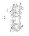
図1に、本実施の形態1であるデジタル携帯電話のシステムの一例を示す。図中、PMは電力増幅器、ANTは信号電波の送受信用のアンテナ、1はフロントエンド装置、2は音声信号をベースバンド信号に変換したり、受信信号を音声信号に変換したり、変調方式切換信号やバンド切換信号を生成したりするベースバンド回路、3は受信信号をダウンコンバートして復調し、ベースバンド信号を生成したり、送信信号を変調したりする変復調用回路、FLT1,FLT2は受信信号からノイズや妨害波を除去するフィルタである。フィルタFLT1はGSM用、フィルタFLT2はDCS用である。 FIG. 1 shows an example of a digital mobile phone system according to the first embodiment. In the figure, PM is a power amplifier, ANT is an antenna for transmitting and receiving signal radio waves, 1 is a front-end device, 2 is a voice signal converted into a baseband signal, a received signal is converted into a voice signal, and a modulation method is switched.
フロントエンド装置1は、インピーダンス整合回路MN1,MN2、ロウパスフィルタLPF1,LPF2、スイッチ回路4a,4b、コンデンサC1,C2および分波器5を有している。インピーダンス整合回路MN1,MN2は電力増幅器PMの送信出力端子に接続されてインピーダンスの整合を行う回路、ロウパスフィルタLPF1,LPF2は高調波を減衰させる回路、スイッチ回路4a,4bは送受信切り換え用の回路、コンデンサC1,C2は受信信号から直流成分をカットする素子、分波器5はGSM900の信号とDCS1800の信号とを分波する回路である。本実施の形態1であるデジタル携帯電話では、電力増幅器PMおよびフロントエンド装置1を1つのモジュールMAに組み立てている。 The
なお、スイッチ回路4a,4bの切換信号CNT1,CNT2は上記ベースバンド回路2から供給される。ベースバンド回路2は、DSP(Digital Signal Processor)やマイクロプロセッサ、半導体メモリ等の複数の半導体集積回路で構成されている。 The switching signals CNT1 and CNT2 of the
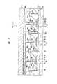
図2に、電力増幅器PMの回路の一例を示す。 FIG. 2 shows an example of a circuit of the power amplifier PM.
電力増幅器PMは、例えばGSM900とDCS1800との2つの周波数帯が使用可能(デュアルバンド方式)であり、それぞれの周波数帯でGMSK変調方式とEDGE変調方式との2つの通信方式を使用可能とする。 The power amplifier PM can use, for example, two frequency bands of GSM900 and DCS1800 (dual band system), and can use two communication systems of the GMSK modulation system and the EDGE modulation system in each frequency band.
この電力増幅器PMは、GSM900用の電力増幅回路Aと、DCS1800用の電力増幅回路Bと、それら電力増幅回路A,Bの増幅動作の制御や補正等を行う周辺回路6とを有している。電力増幅回路A,Bは、それぞれ3つの増幅段A1〜A3,B1〜B3と、3つの整合回路AM1〜AM3,BM1〜BM3とを有している。すなわち、電力増幅器PMの入力端子7a,7bは、入力用の整合回路AM1,BM1を介して1段目の増幅段A1,B1の入力に電気的に接続され、1段目の増幅段A1,B1の出力は段間用の整合回路AM2,BM2を介して2段目の増幅段A2,B2の入力に電気的に接続され、2段目の増幅段A2,B2の出力は段間用の整合回路AM3,BM3を介して最終段の増幅段A3,B3の入力に電気的に接続され、最終段の増幅段A3,B3の出力は出力端子8a,8bと電気的に接続されている。本実施の形態1では、このような電力増幅回路A,Bを構成する素子が1つの半導体チップIC1内に設けられている。 The power amplifier PM includes a power amplifier circuit A for GSM900, a power amplifier circuit B for DCS1800, and a
周辺回路6は、制御回路6Aと、増幅段A1〜A3,B1〜B3にバイアス電圧を印加するバイアス回路6B等を有している。制御回路6Aは、電力増幅回路A,Bに印加する所望の電圧を発生する回路であり、電源制御回路6A1およびバイアス電圧生成回路6A2を有している。電源制御回路6A1は、増幅段A1〜A3,B1〜B3の各々の出力に印加される第1電源電圧を生成する回路である。また、バイアス電圧生成回路6A2は、バイアス回路6Bを制御するための第1制御電圧を生成する回路である。 The
本実施の形態1では、電源制御回路6A1が、電力増幅器PM外部のベースバンド回路2から供給される出力レベル指定信号に基づいて第1電源電圧を生成すると、バイアス電圧生成回路6A2が電源制御回路6A1で生成された第1電源電圧に基づいて第1制御電圧を生成するようになっている。ベースバンド回路2は、出力レベル指定信号を生成する回路である。この出力レベル指定信号は、電力増幅回路A,Bの出力レベルを指定する信号で、携帯電話と、基地局との間の距離、すなわち、電波の強弱に応じた出力レベルに基づいて生成されるようになっている。本実施の形態1では、このような周辺回路6を構成する素子も1つの半導体チップIC1内に設けられている。 In the first embodiment, when the power supply control circuit 6A1 generates the first power supply voltage based on the output level designation signal supplied from the
また、電力増幅器PMを構成する半導体チップIC1の主面(回路素子が形成されている面)に形成された外部用端子と、半導体チップIC1を搭載するモジュール基板の部品搭載面に形成された基板側端子とは、接合材(例えばボンディングワイヤBW)を介して接続されており、この接続材を通じて各増幅段の入出力がモジュール基板の部品搭載面の伝送線路9a1〜9a5,9b1〜9b5,9cと電気的に接続されている。 Also, external terminals formed on the main surface (surface on which circuit elements are formed) of the semiconductor chip IC1 constituting the power amplifier PM, and a substrate formed on the component mounting surface of the module substrate on which the semiconductor chip IC1 is mounted. The side terminals are connected via a bonding material (for example, a bonding wire BW), and through this connection material, the input and output of each amplification stage are transmission lines 9a1 to 9a5, 9b1 to 9b5, 9c on the component mounting surface of the module substrate. And are electrically connected.
1段目の増幅段A1,B1の入力にボンディングワイヤBWを通じて接続された伝送線路9a1,9b1は、それぞれコンデンサCm1,Cm2を介して入力端子10a,10bと電気的に接続されている。1段目の増幅段A1,B1の出力にボンディングワイヤBWを通じて電気的に接続された伝送線路9a2,9b2は、それぞれ高電位側の電源端子11a1,11b1と電気的に接続されているとともに、それぞれ電源端子11a1,11b1の近傍に配置されたコンデンサCm3,Cm4を介して接地電位GNDと電気的に接続されている。2段目の増幅段A2,B2の出力にボンディングワイヤBWを通じて電気的に接続された伝送線路9a3,9b3は、それぞれ高電位側の電源端子11a2,11b2と電気的に接続されているとともに、それぞれ電源端子11a2,11b2の近傍に配置されたコンデンサCm5,Cm6を介して接地電位GNDと電気的に接続されている。最終段目の増幅段A3,B3の出力にボンディングワイヤBWを通じて電気的に接続された伝送線路9a4,9b4は、それぞれ高電位側の電源端子11a3,11b3と電気的に接続されているとともに、それぞれ電源端子11a3,11b3の近傍に配置されたコンデンサCm7,Cm8を介して接地電位GNDと電気的に接続されている。さらに、最終段目の増幅段A3,B3の出力にボンディングワイヤBWを通じて電気的に接続された伝送線路9a5,9b5は、それぞれコンデンサCm9,Cm10を介して出力端子12a,12bと電気的に接続されているとともに、それぞれの線路途中に配置されたコンデンサCm11,Cm12を介して接地電位GNDと電気的に接続されている。周辺回路6の制御用の外部用端子にボンディングワイヤBWを通じて電気的に接続された伝送線路9cは、制御端子13と電気的に接続されている。ボンディングワイヤBWはインダクタとしての機能を有している。また、伝送線路9a1〜9a5,9b1〜9b5はインピーダンス整合用のインダクタとしての機能を有している。また、コンデンサCm1〜Cm12はインピーダンス整合用のコンデンサとしての機能を有しており、チップ部品で構成されている。 The transmission lines 9a1 and 9b1 connected to the inputs of the first amplification stages A1 and B1 through the bonding wires BW are electrically connected to the
次に、モジュールMAに搭載されるフロントエンド装置1および電力増幅器PMの中の代表的な素子の構造を説明する。図3にフロントエンド装置1を構成するロウパスフィルタLPF1,LPF2の構造の説明図を示し、図4〜図7に電力増幅器PMを構成する増幅段A1〜A3,B1〜B3の構造の説明図を示す。 Next, the structure of typical elements in the
まず、フロントエンド装置1を構成するロウパスフィルタLPF1,LPF2の構造の一例を図3(a)に示す要部断面図を用いて説明する。ロウパスフィルタLPF1,LPF2は、1つの基板に複数個の受動素子が形成された集積チップ部品、いわゆるIPD(Integrated Passive Device)であり、その回路構成の一例を図3(b)に示す。なお、図3(a)では、図3(b)に示した回路構成(コンデンサCp1〜Cp3およびLp1〜Lp3)のうち、コンデンサCp2およびインダクタLp2の構造について説明する。 First, an example of the structure of the low-pass filters LPF1 and LPF2 constituting the
集積チップ部品IDを構成する半導体基板(以下、単に基板という)S1は、例えばp+型のシリコン(Si)単結晶からなり、基板S1上には、その記述は省略するが、他の素子、例えばレジスタ等が形成されて絶縁膜14で覆われている。その絶縁膜14上には下層電極15b、容量絶縁膜CSLおよび上層電極15tから構成されるコンデンサCp2が形成されている。下層電極15bおよび上層電極15tは、例えばアルミニウム(Al)合金膜からなり、容量絶縁膜CSLは、例えば窒化シリコン(SiN等)からなる。容量絶縁膜CSLが形成されない領域の下層電極15bと上層電極15tとの間は酸化シリコン(SiO2等)膜16aによって絶縁されている。また、上層電極15tは、窒化シリコン(SiN2等)膜16b、酸化シリコン膜16cおよびポリイミド樹脂膜16dが下層から順に堆積された絶縁膜によって覆われており、ポリイミド樹脂膜16dの表面は平坦化されている。A semiconductor substrate (hereinafter simply referred to as a substrate) S1 that constitutes the integrated chip component ID is made of, for example, p+ type silicon (Si) single crystal. Although not described on the substrate S1, other elements, For example, a register or the like is formed and covered with an insulating
ポリイミド樹脂膜16d上には、例えば銅(以下、Cuと記す)膜からなるインダクタLp2が形成されている。このインダクタLp2は、ポリイミド樹脂膜16d上に堆積された絶縁膜17の所定の領域に溝を形成し、この溝の内部にCu膜を埋め込むことによって形成される。またインダクタLp2は、窒化シリコン膜16b、酸化シリコン膜16cおよびポリイミド樹脂膜16dに形成された接続孔18a〜18cを介してコンデンサCp2の一方の電極である上層電極15tに接続されている。インダクタLp2上はポリイミド樹脂膜20によって覆われており、その一部を開口して、半田からなる瘤状の突起電極であるバンプ電極21がインダクタLp2と接続されている。インダクタLp2とバンプ電極21との間には、ニッケル(以下、Niと記す)膜および金(以下、Auと記す)膜が下層から順に堆積され、パターン形成されたメッキ層22が形成されている。 On the
このように、ロウパスフィルタLPF1,LPF2は、コンデンサCp1〜Cp3とインダクタLp1〜Lp3が一つの基板S1上に形成されている。また、ロウパスフィルタLPF1,LPF2が形成された集積チップ部品IDは、主面を下側に向けた状態(フェイスダウン)でモジュール基板上に搭載され、この集積チップ部品IDの主面に形成された接続端子(例えばバンプ電極21)とモジュール基板の部品搭載面に形成された基板側端子とは電気的に接続されている。 Thus, in the low-pass filters LPF1 and LPF2, the capacitors Cp1 to Cp3 and the inductors Lp1 to Lp3 are formed on one substrate S1. The integrated chip component ID on which the low pass filters LPF1 and LPF2 are formed is mounted on the module substrate with the main surface facing downward (face down), and is formed on the main surface of the integrated chip component ID. The connection terminals (for example, the bump electrodes 21) and the board side terminals formed on the component mounting surface of the module board are electrically connected.
次に、増幅段をnMOSで構成した電力増幅器PM1の内部構成の一例を、図4に示す要部平面図および図5に示す要部断面図を用いて説明する。この電力増幅器PM1は、1つの半導体チップIC1に形成される。 Next, an example of the internal configuration of the power amplifier PM1 in which the amplification stage is composed of nMOS will be described with reference to a plan view of relevant parts shown in FIG. The power amplifier PM1 is formed on one semiconductor chip IC1.
電力増幅器PM1が形成された基板S2は、例えばp+型のシリコン単結晶からなり、その抵抗率が、例えば1〜10mΩ・cm程度の低抵抗基板とされている。基板S2上には、例えばp−型のシリコン単結晶からなるエピタキシャル層EPが形成されている。エピタキシャル層EPの抵抗率は、上記基板S2の抵抗率よりも高い。このエピタキシャル層EPの主面には、増幅段A1〜A3,B1〜B3用のnMOSQnと、整合回路AM1〜AM3,BM1〜BM3用のインダクタL、高Q(Quality factor)値のコンデンサCおよび伝送線路が形成されている。ここでは、2段の増幅段のnMOSQn1,Qn2が示されているが、実際には前述のように2系統の1〜3段の全ての増幅段A1〜A3,B1〜B3が同一の基板S2に形成されている。また、ここで示したnMOSQnは単位MOSを示しており、実際には、この単位MOSが複数個並列に接続されることで1つの増幅段A1〜A3,B1〜B3が構成されている。The substrate S2 on which the power amplifier PM1 is formed is made of, for example, p+ type silicon single crystal, and its resistivity is, for example, a low resistance substrate of about 1 to 10 mΩ · cm. On the substrate S2, an epitaxial layer EP made of, for example, p− type silicon single crystal is formed. The resistivity of the epitaxial layer EP is higher than the resistivity of the substrate S2. The main surface of the epitaxial layer EP includes an nMOS Qn for the amplification stages A1 to A3, B1 to B3, an inductor L for the matching circuits AM1 to AM3 and BM1 to BM3, a capacitor C having a high Q (Quality factor) value and a transmission. A track is formed. Here, nMOS Qn1 and Qn2 of two amplification stages are shown. Actually, however, all the amplification stages A1 to A3 and B1 to B3 of two to three stages are actually the same substrate S2 as described above. Is formed. The nMOS Qn shown here represents a unit MOS, and actually, a plurality of unit MOSs are connected in parallel to form one amplification stage A1 to A3, B1 to B3.
nMOSQnは、例えばLDMOS(Laterally Diffused MOS)等のような横型のMOSで形成されている。nMOSQnの形成領域のエピタキシャル層EPには、p型のウエルPWLが形成されている。このウエルPWLは、例えばホウ素(B)などの不純物をエピタキシャル層EPにイオン注入することで形成されている。さらに、ウエルPWL上には、nMOSQnのゲート絶縁膜23が形成されている。このゲート絶縁膜23は、例えば酸化シリコンからなり、例えば熱酸化法などによって形成されている。このゲート絶縁膜23上には、nMOSQnのゲート電極24が形成されている。このゲート電極24は、例えば多結晶シリコンとその上に形成された金属シリサイド層(例えばチタンシリサイド(TiSi2)層またはコバルトシリサイド(CoSi)層)との積層導体膜で構成されている。nMOSQnのチャネルは、ゲート電極24下のウエルPWLの上部に形成される。The nMOS Qn is formed of a lateral MOS such as an LDMOS (Laterally Diffused MOS). A p-type well PWL is formed in the epitaxial layer EP in the formation region of the nMOS Qn. The well PWL is formed by ion-implanting impurities such as boron (B) into the epitaxial layer EP. Further, an nMOSQn
このゲート電極24の一方の端部近傍のウエルPWLの領域内には、n+型半導体領域25が形成されている。このn+型半導体領域25は、nMOSQnのソースとして機能する領域であり、例えばリン(P)などの不純物をウエルPWLにイオン注入することで形成されている。また、ゲート電極24の他方の端部近傍のエピタキシャル層EPには、n−型半導体領域26aが形成されている。そして、ゲート電極24の他方の端部からn−型半導体領域26aの分だけ離れた箇所には、n+型半導体領域26bがn−型半導体領域26aと電気的に接続された状態で形成されている(LDD(Lightly Doped Drain)構造)。このn−型半導体領域26aおよびn+型半導体領域26bは、nMOSQnのドレインとして機能する領域であり、例えばリンなどの不純物をウエルPWLにイオン注入することで形成されている。An n+
また、各nMOSQnの形成領域のエピタキシャル層EPには、p++型半導体領域27aが上記n+型半導体領域25,26bと接するように形成されている。このp++型半導体領域27aは、例えばホウ素が導入されてなり、平面で見ると、nMOSQnを取り囲むように形成され、断面で見ると、エピタキシャル層EPの主面から基板S2に達するように形成されている。さらに、各nMOSQnのソース用のn+型半導体領域25は、プラグPL1を通じてp++型半導体領域27aと電気的に接続され、そのp++型半導体領域27aを通じて低抵抗な基板S2と電気的に接続されている。Further, in the epitaxial layer EP in the formation region of each nMOS Qn, the p++
後述するように、半導体チップIC1は、その裏面をモジュール基板の部品搭載面に向けた状態でモジュール基板上に搭載される。基板S2は、裏面全面にメタルで形成された電極BLを介して、半導体チップIC1が搭載されるモジュール基板の基板側端子と電気的に接続され、その配線を通じて基準電位(例えば接地電位GNDで0V程度:固定電位)に電気的に接続される。すなわち、基板S2は、半導体チップIC1に形成された複数のnMOSQnの共通の接地部分とされている。 As will be described later, the semiconductor chip IC1 is mounted on the module substrate with its back surface facing the component mounting surface of the module substrate. The substrate S2 is electrically connected to the substrate-side terminal of the module substrate on which the semiconductor chip IC1 is mounted via the electrode BL formed of metal on the entire back surface, and a reference potential (for example, 0 V at the ground potential GND) through the wiring. Degree: fixed potential). That is, the substrate S2 serves as a common ground portion for the plurality of nMOS Qn formed in the semiconductor chip IC1.
前段のnMOSQn1のソース用のn+型半導体領域25と接続されたプラグPL1は、第1層配線M1と電気的に接続されている。このnMOSQn1のゲート電極24は、プラグPL2および第1層配線M1を通じて第2層配線M2と電気的に接続されている。第2層配線M2はnMOSQn1の入力用の配線である。また、このnMOSQn1のドレイン用のn+型半導体領域26bは、プラグPL3を通じて第1層配線M1と電気的に接続されている。この第1層配線M1は、インダクタLの一端と電気的に接続されている。The plug PL1 connected to the n+ -
このインダクタLは、例えばスパイラル状の第2層配線M2で形成されている。このインダクタLの外周は、シールド用の第1層配線M1、第2層配線M2、プラグPL4およびp++型の半導体領域27bにより取り囲まれている。シールド用の第1層配線M1、第2層配線M2、プラグPL4およびp++型半導体領域27bは、互いに電気的に接続されており(インダクタLとは絶縁されている)、p++型半導体領域27bを通じて低抵抗な基板S2と電気的に接続されて接地電位GNDに設定されている。このインダクタLの他端は、第2層配線M2を通じてコンデンサCの上部電極Caと電気的に接続されている。The inductor L is formed of, for example, a spiral second layer wiring M2. The outer periphery of the inductor L is surrounded by a first layer wiring M1, a second layer wiring M2, a plug PL4, and a p++
コンデンサCの上部電極Caの下層の配線層には、絶縁膜を挟んで上部電極Caと対向するように下部電極Cbが設けられている。この下部電極Cbは、プラグPL5を通じてp++型半導体領域27cと電気的に接続され、さらにp++型半導体領域27cを通じて低抵抗な基板S2と電気的に接続されている。このコンデンサCの外周も、シールド用の第1層配線M1、第2層配線M2、プラグPL6およびp++型半導体領域27dにより取り囲まれている。シールド用の第1層配線M1、第2層配線M2、プラグPL6およびp++型半導体領域27dは、互いに電気的に接続されており(コンデンサC1とは絶縁されている)、p++型半導体領域27dを通じて低抵抗な基板S2と電気的に接続されて接地電位GNDに設定されている。このコンデンサCの上部電極Caは、第2層配線M2を通じてnMOSQn2のゲート電極24と電気的に接続されている。なお、プラグPL1〜PL6は、例えばタングステン(W)等のようなメタルで形成されている。また、第1層配線M1および第2層配線M2は、例えばアルミニウムまたはCuを主配線材料とするメタルで形成されている。In the wiring layer below the upper electrode Ca of the capacitor C, a lower electrode Cb is provided so as to face the upper electrode Ca with an insulating film interposed therebetween. The lower electrode Cb is,p ++
電力増幅器PM1が形成された半導体チップIC1は、主面を上側に向けた状態(フェイスアップ)でモジュール基板上に搭載され、この半導体チップIC1の外部用端子とモジュール基板の部品搭載面に形成された基板側端子とは接合材、例えばAuの細線からなるボンディングワイヤBWによって電気的に接続されている。 The semiconductor chip IC1 on which the power amplifier PM1 is formed is mounted on the module substrate with the main surface facing upward (face up), and is formed on the external terminals of the semiconductor chip IC1 and the component mounting surface of the module substrate. The substrate-side terminal is electrically connected by a bonding material, for example, a bonding wire BW made of a fine Au wire.
次に、増幅段をヘテロ接合型バイポーラトランジスタ(HBT:Hetero-junction Bipolar Transistor)で構成した電力増幅器PM2の内部構成の一例を、図6に示す要部平面図および図7に示す要部断面図(図6のA−A線における切断面)を用いて説明する。この電力増幅器PM1は、増幅段をnMOSで構成した場合と同様に、1つの半導体チップIC1に形成される。 Next, an example of the internal configuration of the power amplifier PM2 in which the amplification stage is configured by a hetero-junction bipolar transistor (HBT) is illustrated in a plan view of the main part shown in FIG. 6 and a cross-sectional view of the main part shown in FIG. This will be described with reference to (a cut surface along line AA in FIG. 6). The power amplifier PM1 is formed on one semiconductor chip IC1 as in the case where the amplification stage is configured by an nMOS.
前記図2に示した増幅段A1〜A3,B1〜B3のうち初段に使用される増幅段A1,B1はノイズの低減が要求されることから、例えばnMOSによって構成されるのが好ましいが、終段に使用される増幅段A3,B3は、高増幅率が要求されることから、例えばHBTによって構成されることが好ましい。なお、中段に使用される増幅段A2,B2はnMOSまたはHBTのどちらを使用してもよい。従って、例えば増幅段A1,A2,B1,B2をnMOSで構成し、増幅段A3,B3をHBTで構成した場合は、電力増幅器は1つの半導体チップに形成されているのではなく、2つの半導体チップに分けて形成される。また、実際には、1つの増幅段は単位HBTが複数個並列に接続されることで形成されるが、ここでは、例えば終段に使用される増幅段A3を構成する3つのHBT1〜HBT3を説明する。 Of the amplification stages A1 to A3 and B1 to B3 shown in FIG. 2, the amplification stages A1 and B1 used in the first stage are required to be reduced in noise. The amplification stages A3 and B3 used for the stages are preferably composed of, for example, an HBT because a high amplification factor is required. The amplification stages A2 and B2 used in the middle stage may use either nMOS or HBT. Therefore, for example, when the amplification stages A1, A2, B1, and B2 are configured by nMOS and the amplification stages A3 and B3 are configured by HBT, the power amplifier is not formed on one semiconductor chip but on two semiconductors. It is divided into chips. Also, in practice, one amplification stage is formed by connecting a plurality of unit HBTs in parallel. Here, for example, three HBT1 to HBT3 constituting the amplification stage A3 used at the final stage are arranged. explain.
HBT1〜HBT3が形成された基板S3は、例えば半絶縁性のGaAs基板S3からなる。HBT1〜HBT3は、例えば、メサアイソレーション28aで他の素子から分離されたn+型GaAs層よりなるサブコレクタ層28上に、所定間隔を置いて形成されている。ここで、HBT1〜HBT3は同様の構成をしているため、HBT1〜HBT3のうち、例えば、左端に形成されているHBT1の構成について説明する。HBT1は、サブコレクタ層28上に形成されたコレクタ電極29と、このコレクタ電極29とは所定間隔だけ離間して形成されたコレクタメサ30とを有している。コレクタ電極29は、例えば、Au等から構成される。The substrate S3 on which the HBT1 to HBT3 are formed is made of, for example, a semi-insulating GaAs substrate S3. HBT1 to HBT3 are formed, for example, on the
コレクタメサ30は、例えばn型GaAs層より形成され、このコレクタメサ30とコレクタ電極29とはサブコレクタ層28を介して電気的に接続されている。そして、コレクタメサ30上には、例えば、p型GaAs層よりなるベースメサ31が形成されている。 The
ベースメサ31上の周辺領域にはAu等よりなるベース電極32が形成されている。すなわち、ベースメサ31上にコの字形状を反時計周りに90度回転させた形状をしたベース電極32が形成されている。そして、ベースメサ31の略中央部上にエミッタ層33が形成され、このエミッタ層33上にエミッタ電極34が形成されている。エミッタ層33は、例えばn型InGaP層、GaAs層およびInGaAs層を下層から順に堆積した積層膜により形成され、エミッタ電極34は、例えばタングステンシリサイド(WSi)により形成されている。 A
このように、ベースメサ(p型GaAs層)31とエミッタ層(n型InGaP層)33との間には異種半導体接合(ヘテロ接合)が形成されている。また、本実施の形態1におけるHBT1は、コレクタ電極29が一番下層に形成され、一番上層にエミッタ電極34が形成された構造をしており、中間層にベース電極32が形成された構造となっている。 Thus, a heterogeneous semiconductor junction (heterojunction) is formed between the base mesa (p-type GaAs layer) 31 and the emitter layer (n-type InGaP layer) 33. The
HBT1は上記のように構成されており、このHBT1と同様の構成を有するHBT2、HBT3が横方向に並んで形成されている。 The
HBT1〜HBT3の各コレクタ電極29は、導電材料を埋め込んだ接続孔35aによって第1コレクタ配線M1cに共通接続している。すなわち、第1コレクタ配線M1cは、HBT1〜HBT3の各コレクタ電極29を電気的に接続するものであり、第1配線層に形成されている。また、HBT1〜HBT3の各ベース電極32は、導電材料を埋め込んだ接続孔35bによって第1ベース配線M1bに共通接続している。この第1ベース配線M1bも第1コレクタ配線M1cと同層である第1配線層に形成されている。 The
HBT1〜HBT3の各エミッタ電極34は、導電性材料を埋め込んだ接続孔36aによってエミッタ配線M2eに共通接続している。すなわち、エミッタ配線M2eは、HBT1〜HBT3が並んでいる方向に延びており、導電性材料を埋め込んだ接続孔36aを介して各エミッタ電極34と接続している。このエミッタ配線M2eは、第1配線層の上部にある第2配線層に形成されている。エミッタ配線M2eが第2配線層に形成されているのは、エミッタ電極34がベース電極32やコレクタ電極29よりも高い位置に形成されているためである。また、第1コレクタ配線M1cは、導電性材料を埋め込んだ接続孔36bによって第2コレクタ配線M2cに接続し、第1ベース配線M1bは、導電性材料を埋め込んだ接続孔36bによって、第2ベース配線M2bに接続している。これら第2コレクタ配線M2cや第2ベース配線M2bは第2配線層に形成されている。 Each
第2配線層に形成されたエミッタ配線M2e上には直接エミッタバンプ電極37aが形成されている。すなわち、エミッタバンプ電極37aは、第3配線層に形成されるが、この第3配線層は、第2配線層との間に接続孔を介さずに直接第2配線層上に形成されている。 An
エミッタバンプ電極37aは、HBT1〜HBT3が並んでいる方向に延びており、第2配線層に形成されたエミッタ配線M2eを介して、各エミッタ電極34に電気接続している。また、第2コレクタ配線M2c上には直接コレクタバンプ電極37cが形成され、第2ベース配線M2b上には直接ベースバンプ電極37bが形成されている。これらコレクタバンプ電極37c、エミッタバンプ電極37eおよびベースバンプ電極37bは、同じ第3配線層に形成されているため、半導体チップICの素子形成面は平坦化されている。 The
電力増幅器PM2が形成された半導体チップIC1は、主面を下側に向けた状態(フェイスダウン)でモジュール基板上に搭載され、コレクタバンプ電極37c,エミッタバンプ電極37eおよびベースバンプ電極37bがモジュール基板の部品搭載面に形成された基板側端子に接続される。 The semiconductor chip IC1 on which the power amplifier PM2 is formed is mounted on the module substrate with the main surface facing downward (face-down), and the collector bump electrode 37c, the emitter bump electrode 37e, and the
次に、表面実装部品をモジュール基板上に搭載する1次実装後のモジュールMAの構成を説明する。図8は、本実施の形態1であるデジタル携帯電話機におけるモジュールMAの1次実装の一例を示している。ここでは、前述したフロントエンド装置1および電力増幅器PMを1つのモジュールMAに組み立てた構成となっているが、これに限定されないことは言うまでもない。例えばフロントエンド装置1と電力増幅器PMとを別々のモジュールとして構成してもよい。また、ここでは、増幅段をnMOSで構成した電力増幅器PM1を有する半導体チップIC1を例に挙げて説明するが、増幅段をHBTで構成した電力増幅器PM2を有する半導体チップを用いてもよい。この場合は、主面をモジュール基板の主面へ向けたフェイスダウン接続となる。さらに、増幅段の前段をnMOSで構成し、後段をHBTで構成した場合は、電力増幅器PMに2つの半導体チップが用いられる。 Next, the configuration of the module MA after the primary mounting in which the surface mounting component is mounted on the module substrate will be described. FIG. 8 shows an example of the primary mounting of the module MA in the digital mobile phone according to the first embodiment. Here, the
モジュールMAは、複数枚の絶縁体板を積層して一体化した多層配線構造を有するPCB(第1配線基板)38を基板としている。PCB38の部品搭載面(第1面)には、例えばCu膜からなる基板側端子40a1,40a2,40b,40cおよび配線等がパターン形成されており、裏面(第2面)には、例えばCu膜からなる電極42G,42Sがパターン形成されている。さらに、図8には、PCB38の部品搭載面に搭載される表面実装部品として、能動素子が形成された半導体チップIC1,IC2と、1つのチップ基板に1個の受動素子が形成された単体チップ部品43と、1つのチップ基板に複数個の受動素子が形成された集積チップ部品44とを例示している。さらに、これら表面実装部品は高弾性の封止用の樹脂45によって覆われている。樹脂45は、例えば高弾性エポキシの樹脂であり、その弾性率の許容範囲は、180℃以上の温度において、2GPa以上であることが好ましい。 The module MA uses a PCB (first wiring board) 38 having a multilayer wiring structure in which a plurality of insulating plates are stacked and integrated as a substrate. On the component mounting surface (first surface) of the
図8に例示した2つの半導体チップIC1,IC2のうち、一方の半導体チップIC1は受動素子に比べて発熱量が多い能動素子、例えば電力増幅器PM1であり、他方の半導体チップIC2は能動素子に比べて発熱量が少ない能動素子、例えばアンテナスイッチである。半導体チップIC1,IC2の主面に形成された複数の外部用端子(表面電極)は、これに対応するPCB38の基板側端子40cと接合材により接続されている。ここでは、接合材に、Auの細線からなるボンディングワイヤBWを用いる。 Of the two semiconductor chips IC1 and IC2 illustrated in FIG. 8, one semiconductor chip IC1 is an active element that generates more heat than the passive element, for example, the power amplifier PM1, and the other semiconductor chip IC2 is compared to the active element. Active elements that generate less heat, such as antenna switches. A plurality of external terminals (surface electrodes) formed on the main surfaces of the semiconductor chips IC1 and IC2 are connected to the corresponding
半導体チップIC1は、その裏面をPCB38の部品搭載面に形成されたチップ搭載用の基板側端子(第1基板側端子)40a1と接合し、ダイボンド材として半田(第1半田)46を用いてPCB38上に固定されている。この半田46は、例えば280℃以上の温度で液状となる高融点半田、例えばPbを含むPb−Sn半田を用いる。Pb−Sn半田のSnの含有量は、例えば2から30wt%が適切な範囲と考えられる(他の条件によってはこの範囲に限定されないことはもとよりである)。また、量産に適した範囲としては2から10wt%が考えられるが、さらに10wt%を中心値とする周辺範囲が最も好適と考えられる。高融点半田を用いることにより、多量の発熱が生じても半導体チップIC1とPCB38との接着強度が確保できて、半導体チップIC1のPCB38からの剥離を防ぐことができる。 The back surface of the semiconductor chip IC1 is bonded to a chip mounting substrate side terminal (first substrate side terminal) 40a1 formed on the component mounting surface of the
半導体チップIC1の裏面電極(例えば図5の裏面電極BL)は、PCB38の部品搭載面から裏面へ貫通して形成された複数の放熱ビア47内の導電性材料を通じてPCB38の裏面に形成された電極42Gと電気的かつ熱的に接合されている。この電極42Gには基準電位(例えば接地電位GNDで0V程度)が供給される。すなわち、PCB38の裏面の電極42Gに供給された基準電位は、放熱ビア47および基板側端子40a1を通じて半導体チップIC1の裏面に供給されるようになっている。また、逆に半導体チップIC1の動作時に発生した熱は、半導体チップIC1の裏面からチップ搭載用の基板側端子40a1および放熱ビア47を通じてPCB38の裏面に形成された電極42Gに伝わり放散されるようになっている。PCB38の裏面に形成された外周近傍の電極42Sは、信号用の電極を示している。 The back surface electrode of the semiconductor chip IC1 (for example, the back surface electrode BL in FIG. 5) is an electrode formed on the back surface of the
半導体チップIC2は、その裏面をPCB38の部品搭載面に形成されたチップ搭載用の基板側端子40a2と接合し、ダイボンド材として半田48aを用いてPCB38上に固定されている。この半田48aは、例えば200℃以上の温度で液状となるPbを含まないPbフリー半田、例えばAg3wt%およびCu0.5w%を含むSn(以下、Sn−3Ag−0.5Cu半田と記す)を用いる。 The back surface of the semiconductor chip IC2 is bonded to a chip mounting board side terminal 40a2 formed on the component mounting surface of the
単体チップ部品43は、例えばコンデンサ、インダクタ、レジスタまたはフェライトビーズ等の受動素子が1つの基板上に搭載された表面実装部品である。フェライドビーズとは、フェライト素子の中に通電用の内部電極を埋め込んだ構造をしており、フェライトが磁性体として働くことで電磁妨害(EMI:Electromagnetic Interference)ノイズの元となる高周波電流成分を吸収する素子である。単体チップ部品43は、その裏面をPCB38の部品搭載面に対向させてPCB38上に搭載されており、単体チップ部品43の両端に形成された接続端子が、半田(第2半田)48bを介してPCB38の部品搭載面に形成された基板側端子(第2基板側端子)40bと半田接続されている。この半田接続には、Pbを含まないPbフリー半田、例えばSn−3Ag−0.5Cu半田を用いる。単体チップ部品43の裏面とPCB38の部品搭載面との距離は、例えば10μm程度であるが、この隙間には封止用の樹脂45がボイドを形成することなく充填されている。 The
集積チップ部品44は、例えば図3に示したロウパスフィルタLPF1,LPF2等の受動素子が複数個形成された表面実装部品である。集積チップ部品44は、PCB38にフリップチップ接続されており、集積チップ部品44の主面をPCB38の部品搭載面に対向させて、集積チップ部品44の主面に形成された接続端子(例えば図3のバンプ電極21)が、半田(第2半田)48cを介してPCB38の部品搭載面に形成された基板側端子(第2基板側端子)40bと半田接続されている。この半田接続には、Pbを含まないPbフリー半田、例えばSn−3Ag−0.5Cu半田を用いる。集積チップ部品44の主面とPCB38の部品搭載面との距離は、例えば10〜20μm程度であるが、この隙間にも封止用の樹脂45がボイドを形成することなく充填されている。 The
なお、半導体チップIC2、単体チップ部品43および集積チップ部品44の半田接続で用いる半田材料としてPbフリー半田を用いるとしたが、半田材料は、これに限定されるものではなく種々変更可能であり、例えばPbを含むSn(以下、Pb−Sn半田と記す)を用いてもよい。しかし、欧州におけるPb規制を考慮するとPbフリー半田が好ましい。 Although the Pb-free solder is used as the solder material used for the solder connection of the semiconductor chip IC2, the
また、半導体チップIC1,IC2にボンディングワイヤBWを用いているため、全ての基板側端子40a1,40a2,40b,40cの表面にはメッキ層が形成されている。メッキ層は、例えば下層から順にNi層およびAu層がメッキされた積層膜からなる。従って、単体チップ部品43は、その接続端子においてメッキ層と半田接続され、集積チップ部品44は、その接続端子においてメッキ層と接続されるとともに、半導体チップIC1,IC2の主面に形成された外部用端子に接続するボンディングワイヤBWは、基板側端子40cの表面のメッキ層と接続されている。 Further, since the bonding wires BW are used for the semiconductor chips IC1 and IC2, plating layers are formed on the surfaces of all the substrate side terminals 40a1, 40a2, 40b, and 40c. For example, the plating layer is a laminated film in which a Ni layer and an Au layer are plated in order from the lower layer. Accordingly, the
次に、製品に組み込むために、さらに上記モジュールMAを実装配線基板(マザーボード)上に搭載する2次実装後のモジュールMAの構成を説明する。図9は、本実施の形態1であるデジタル携帯電話機におけるモジュールMAの2次実装の一例を示している。 Next, the configuration of the module MA after the secondary mounting in which the module MA is further mounted on a mounting wiring board (motherboard) for incorporation into a product will be described. FIG. 9 shows an example of secondary mounting of the module MA in the digital mobile phone according to the first embodiment.
マザーボード(第2配線基板)50は、例えば多層配線構造を有するプリント配線基板からなり、その主面(第1面)には、モジュールMAと、その他に複数の単体チップ部品51等が搭載されている。モジュールMAは、前述したように、その基板にPCB38を採用し、PCB38の部品搭載面は樹脂45により覆われており、これによりPCB38の部品搭載面に搭載された半導体チップIC1,IC2、単体チップ部品43および集積チップ部品44等が封止されている。また、モジュールMAは、PCB38の裏面に形成された電極42G,42S等をマザーボード50の主面に向けた状態でマザーボード50上に搭載されている。上記電極42G,42Sは、接合材、例えば半田(第3半田)53を介してそれぞれマザーボード50の主面に形成されたプリント配線と接続されている。 The mother board (second wiring board) 50 is composed of, for example, a printed wiring board having a multilayer wiring structure, and the main surface (first surface) is mounted with a module MA and a plurality of other
次に、本実施の形態1によるモジュールMAの1次実装工程および2次実装工程の一例を図10〜図19を用いて工程順に説明する。図10はモジュールMAの組み立て手順を説明する工程図、図11は4層の銅配線が形成されたPCB38の一部断面を拡大した図、図12〜図19は1つのモジュール領域を示す半導体装置の要部断面図である。 Next, an example of the primary mounting process and the secondary mounting process of the module MA according to the first embodiment will be described in the order of processes with reference to FIGS. FIG. 10 is a process diagram for explaining the assembly procedure of the module MA, FIG. 11 is a partially enlarged view of the
モジュールMAの1次実装工程について説明する。 The primary mounting process of the module MA will be described.
まず、例えば図11に示すPCB38を準備する。PCB38は、複数(例えば120個程度)の装置領域であるモジュール領域が区画ラインによって区画形成された多数個取り基板であり、例えばモジュール領域が120個形成されている場合、一例として、その大きさは80mm×80mm程度、厚さは0.3mm程度である。PCB38は、コア材56の上下に内層用Cu膜57(2層目および3層目配線)がパターン形成され、これら内層用Cu膜57はプリプレグ58と呼ばれる絶縁材料によって挟まれている。内層用Cu膜57の厚さは、例えば0.2mm程度、プリプレグ58の厚さは、例えば0.06mm程度である。さらにプリプレグ58の外面は、例えば各モジュール領域の半導体チップまたはチップ部品などの表面実装部品が搭載される面(部品搭載面)であって、プリプレグ58に密着して外層用Cu膜59(1層目および4層目配線)がパターン形成されている。この外層用Cu膜59は、図8で示した基板側端子40a1,40a2,40b,40cであり、その厚さは、例えば0.02mm程度である。外層用Cu膜59の表面には、例えばNi層およびAu層が下層から順に形成されたメッキ層が形成されている。さらに、半導体チップまたはチップ部品などの表面実装部品が実装される領域を除いて、外層用Cu膜59上はソルダーレジスト60により覆われている。ソルダーレジスト60の厚さは、例えば0.025〜0.05mm程度である。 First, for example, a
上下に位置する2層の内層用Cu膜57との間、または内層用Cu膜57と外層用Cu膜59との間は、コア材56またはプリプレグ58を貫通するCu膜が埋め込まれたビア61を介して電気的に接続されている。また、各モジュール領域の半導体チップIC1が搭載される領域には、コア材56およびプリプレグ58を貫通するCu膜が埋め込まれた放熱ビア47が形成されている。コア材56、プリプレグ58およびソルダーレジスト60は、例えばエポキシなどの樹脂からなる。 A via 61 in which a Cu film penetrating the
次に、半田印刷を行う(図10の工程P1)。まず、図12に示すように、PCB38の部品搭載面に印刷用マスク63を載せる。印刷用マスク63は、例えば厚さ0.2mm程度のステンレスからなり、エッチングによって所望する箇所に穴が開けられている。続いて、印刷用マスク63とPCB38との位置を決めた後、半田48を印刷用マスク63の一端に載せ、スキージ65を用いて半田48を動かす。半田48はPbフリー半田であり、例えばSn−3Ag−0.5Cu半田を用いる。これにより、図13に示すように、半田48a,48b,48cをPCB38の部品搭載面に形成された所定の基板側端子40a2,40b上に印刷する。この時、スキージ65は、例えば45℃程度傾けて半田48がローリングするように印刷する。続いて、図14に示すように、印刷用マスク63を取り除くことにより、後の工程において単体チップ部品43、集積チップ部品44および半導体チップIC2が接続される基板側端子40a2,40b上に半田48a,48b,48cを残す。 Next, solder printing is performed (step P1 in FIG. 10). First, as shown in FIG. 12, a
次に、半導体チップIC1用の半田塗布する(図10の工程P2)。図15に示すように、ポッティングノズル66から半導体チップIC1が搭載される箇所に半田46を供給し、半導体チップIC1が接続される基板側端子40a1上に半田46を塗り付ける。半田46は、例えば280℃以上の温度で液状となるPbを含む高融点半田を用いる。 Next, solder for the semiconductor chip IC1 is applied (step P2 in FIG. 10). As shown in FIG. 15, the
次に、図16に示すように、単体チップ部品43、集積チップ部品44をおよび半導体チップIC1,IC2を所定の基板側端子40a1,40a2,40b上に配置する(図10の工程P3)。続いて、図17に示すように、PCB38をヒートブロック67上に載せてリフローを行い、半田46,48a,48b,48cを溶かすことによって上記表面実装部品を一括して半田接続する(図10の工程P4)。この時、PCB38を構成するソルダーレジスト60が焦げたり、プリプレグ58がコア材56から剥離したりするのを防ぐために、ヒートブロック67は、280℃未満の温度、例えば250℃に設定される。このヒートブロック67による加熱により半田48a,48b,48cが溶融して、単体チップ部品43の両端の接続端子と基板側端子40bとを半田48bで半田接続し、集積チップ部品44の接続端子と基板側端子40bとを半田48cで半田接続し、半導体チップIC2と基板側端子40a2とを半田48cで半田接続する。 Next, as shown in FIG. 16, the
さらに、ヒートブロック67による加熱に加えて、半導体チップIC1を280℃以上の温度、例えば330〜350℃の温度で局所加熱する。半導体チップIC1の局所加熱には、例えばホットジェット68を用いる。ホットジェット68のノズルから300℃以上のドライエアーを吹き出すことにより、半田46が溶融して半導体チップIC1と基板側端子40a1とが半田接続する。ホットジェットは、内径1〜2mm程度のパイプの周囲をニクロム線で巻いた構造をしており、そのパイプの中に導入された空気をニクロム線により所望の温度に加熱して、ホットジェット68のノズルから300℃以上のドライエアーを吹き出す。ホットジェット68による1回の加熱時間は、例えば5秒程度、ドライエアーの流量は、例えば8リットル/min程度である。なお、半導体チップIC1の裏面が半田46を介してヒートブロック67に接触していると、熱が拡散して逃げてしまい、半導体チップIC1の温度が上昇しないことがある。これを避けるため、ヒートブロック67の半導体チップIC1が搭載される領域に凹部67aを形成し、半導体チップIC1の裏面とヒートブロック67とが接触しないようにする。 Further, in addition to the heating by the
このように、半田48a,48b,48cを用いた単体チップ部品43、集積チップ部品44および半導体チップIC2の半田接続は、ヒートブロック67上に各表面実装部品が搭載されたPCB38を載せて280℃未満の温度の加熱処理により行われ、同時に半田46を用いた半導体チップIC1の半田接続は、ホットジェットを用いた280℃以上の温度の加熱処理により行われる。これにより、熱によるPCB38の損傷、例えばソルダーレジスト60の焦げやプリプレグ58のコア材56からの剥離、およびPbフリー半田(半田48a,48b,48c)の溶融を生ずることなく、高融点半田(半田46)を用いて半導体チップIC1をPCB38に半田接続することができる。その結果、PCB38上に強い接着強度を有する半導体チップIC1を搭載することができる。 As described above, the solder connection of the
次に、各表面実装部品が半田接続されたPCB38を洗浄し(図10の工程P5)、続いて、ワイヤボンディング(図10の工程P6)を行う。ここでは、図18に示すように、半導体チップIC1,IC2の上面に露出したパッドと、その表面にメッキ層が形成された基板側端子40cとをボンディングワイヤBW、例えばAu線を用いて接続する。 Next, the
次に、各表面実装部品を樹脂45によって封止するトランスファーモールドを行う(図10の工程P7)。モールド装置の上金型を上げて、各表面実装部品が半田接続されたPCB38を下金型に設置する。その後、上金型を下げてPCB38を固定する。上金型には、上金型と下金型との間の成型金型内の空気および樹脂を外部へ送り出すためのエアベントが設けられている。続いて、成型金型内を強制的に、例えば1Torr以下に減圧した後、樹脂タブレットをプレヒータで加熱し、樹脂粘度を下げてから液状化した樹脂45を成型金型内へ圧送する。樹脂45は、例えば熱硬化性のエポキシ樹脂が用いられる。続いて、成型金型内に充填された封止用樹脂を重合反応により硬化させた後、上金型と下金型とを開けて、樹脂45で覆われたPCB38を取り出す。その後、不要な封止用の樹脂45を除去し、さらに、ベーク処理を行って(図10の工程P8)重合反応を完成させることにより、図19に示す各表面実装部品が樹脂45により封止されたモジュールMAが完成する。 Next, transfer molding is performed to seal each surface mount component with the resin 45 (step P7 in FIG. 10). The upper die of the molding apparatus is raised, and the
このように、成型金型内を減圧した後に樹脂45を投入することにより、樹脂45の流動性を図ることができるので、狭い隙間、例えば単体チップ部品43の裏面とPCB38の部品搭載面との隙間(10μm程度)および集積チップ部品44の主面とPCB38の部品搭載面との隙間(30μm程度)に、ボイドの形成を防いで樹脂45を充填することができる。その結果、次に説明するモジュールMAの組み立て時に、例えば250℃程度の温度の熱が加えられてPbフリー半田の半溶融が生じても、Pbフリー半田のフラッシュ状の流れを防ぐことができるので、例えば単体チップ部品43の両端の接続端子間または集積チップ部品44の主面の接続端子間が繋がることはなく、短絡を回避することができる。 Thus, by introducing the
次に、封止用樹脂45およびPCB38をダイシングラインに沿って切断して、個々のモジュールMAに分離する(図10の工程P9)。その後、モジュールMAを覆う樹脂45の表面に、例えば商標、品名、ロット番号などを捺印した後、製品規格に照らした項目でモジュールMAの電気的特性を測定し、モジュールMAを選別する(図10の工程P10)。 Next, the sealing
次に、モジュールMAの2次実装行程について説明する。 Next, the secondary mounting process of the module MA will be described.
PCB38の裏面には、マザーボード50に実装可能なように、半田接続用の電極42G,42Sが形成されている。まず、マザーボード50に半田ペーストを印刷する。続いて、モジュールMAをマザーボード50上に配置した後、例えば250℃程度の温度でリフロー処理を行い、モジュールMAをマザーボード50上に実装する。その後、電気的特性のテストを行い、実装完成となる。2次実装における上記リフロー処理では、Pbフリー半田を用いて単体チップ部品43、集積チップ部品44および半導体チップIC2をPCB38に半田接続する温度(例えば220℃程度)よりも高い温度(例えば250℃程度)を用いるため、Pbフリー半田が溶融する場合がある。しかし、モジュールMAとマザーボード50との半田接続に用いる半田量に比べて、単体チップ部品43、集積チップ部品44または半導体チップIC2とPCB38との半田接続に用いるPbフリー半田の半田量を少くできることから、溶融する半田量はわずかであり、フラッシュ状となり単体チップ部品43または集積チップ部品44の接続端子間を短絡するまでには至らない。 On the back surface of the
なお、本実施の形態1では、PCB38に搭載された各表面実装部品を高弾性の樹脂45によって覆った場合について説明したが、これに限定されるものではなく、例えば低弾性の樹脂、例えばシリコーン樹脂を用いることも可能である。 In the first embodiment, the case where each surface mount component mounted on the
また、GSM900とGSM1800の2つの周波数帯の電波を取り扱うことが可能なデュアルバンド方式に適用した場合について説明したが、これに限定されるものではなく、例えばGSM900、GSM1800およびGSM1900との3つの周波数帯の電波を取り扱うことが可能なトリプルバンド方式に適用しても良い。また、800MHz帯、850MHz帯でも対応できる。 Further, the case where the present invention is applied to a dual band system capable of handling radio waves in two frequency bands of GSM900 and GSM1800 has been described, but the present invention is not limited to this. For example, three frequencies of GSM900, GSM1800, and GSM1900 are used. You may apply to the triple band system which can handle the electromagnetic wave of a belt. Moreover, it can respond also to 800 MHz band and 850 MHz band.
このように、本実施の形態1によれば、単体チップ部品43および集積チップ部品44の半田接続が、ヒートブロック67を用いた280℃未満の温度の加熱処理により行われるので、Pbフリー半田を用いることができ、また、熱によるPCB38の損傷、例えばソルダーレジスト60の焦げやプリプレグ58のコア材56からの剥離を回避することができる。さらに、上記半田接続と同時に半導体チップIC1の半田接続が、ホットジェットを用いた280℃以上の温度の加熱処理により行われるので、半導体チップIC1の半田接続に高融点半田を用いることができるので、強い接着強度を有する半導体チップIC1をPCB38上に搭載することができる。 As described above, according to the first embodiment, the solder connection between the
また、成型金型内を減圧して樹脂45を投入することにより、樹脂45の流動性を図ることができるので、例えば単体チップ部品43の裏面とPCB38の部品搭載面との狭い隙間、また集積チップ部品44の主面とPCB38の部品搭載面との狭い隙間にボイドを形成することなく樹脂45を充填することができる。これにより、マザーボード50にモジュールMAを半田接続した後に、例えば250℃程度の温度の熱が加えられてモジュールMA内のPbフリー半田の半溶融が生じても、Pbフリー半田のフラッシュ状の流れを防ぐことができるので、例えば単体チップ部品43の両端の接続端子間または集積チップ部品44の主面の接続端子間が繋がることはなく、短絡を回避することができる。 Further, by reducing the pressure in the molding die and introducing the
(実施の形態2)
本実施の形態2である各表面実装部品を一括してモジュール基板に半田接続する実装行程の他の例を説明する。図20は、前記実施の形態1の図16に続く実装方法を説明する半導体装置の要部断面図である。(Embodiment 2)
Another example of the mounting process in which the surface-mounted components according to the second embodiment are collectively solder-connected to the module substrate will be described. FIG. 20 is a fragmentary cross-sectional view of the semiconductor device for explaining the mounting method subsequent to FIG. 16 of the first embodiment.
前記実施の形態1と同様に、ホットジェット68を用いて半導体チップIC1を280℃以上の温度、例えば330〜350℃の温度で局所加熱して、半導体チップIC1と基板側端子40a1とを高融点半田で接続するが、この時、ヒートブロック67を加熱せず、PCB38上に搭載された全ての表面実装部品をカバー68aで覆う。Pbフリー半田は、半導体チップIC1上にホットジェット68のノズルから吹き出したドライエアーがカバー68a内で拡散して生じる余熱により溶融して、単体チップ部品43と基板側端子40b、集積チップ部品44と基板側端子40b、および半導体チップIC2と基板側端子40a2とが接続される半導体チップIC1以外の領域は、ホットジェット68のノズルから吹き出したドライエアーが逃げる熱のみで加熱するので、280℃未満の温度、例えば150℃程度に抑えることができる。これにより、ソルダーレジスト60が焦げたり、プリプレグ58がコア材56から剥離したりするのを防ぐことができる。この半田接続以後の工程は前記実施の形態1と同じなので説明を省略する。 As in the first embodiment, the semiconductor chip IC1 is locally heated using the
このように、本実施の形態2によれば、Pbフリー半田を用いた単体チップ部品43、集積チップ部品44または半導体チップIC2の半田接続は、ホットジェット68から吹き出すドライエアーの拡散を用いて280℃未満の温度の加熱処理により行われる。これにより、Pbフリー半田の溶融や熱によるPCB38の損傷を防ぐことができる。 As described above, according to the second embodiment, the solder connection of the
(実施の形態3)
本実施の形態3である表面実装部品を一括してモジュール基板に半田接続する実装行程の他の例を説明する。図21は、前記実施の形態1の図16に続く実装方法を説明する半導体装置の要部断面図である。(Embodiment 3)
Another example of the mounting process in which the surface mounting components according to the third embodiment are collectively soldered to the module substrate will be described. FIG. 21 is a fragmentary cross-sectional view of the semiconductor device for explaining the mounting method following FIG. 16 of the first embodiment.
前記実施の形態2と同様に、ヒートブロック67を加熱せず、PCB38上に搭載された全ての表面実装部品をカバー68aで覆い、ホットジェット68を用いて半導体チップIC1を280℃以上の温度、例えば330〜350℃の温度で局所加熱して、半導体チップIC1と基板側端子40a1とを高融点半田で接続する。また、ホットジェット68のノズルから吹き出したドライエアーがカバー68a内で拡散して生じる余熱によりObフリー半田を溶融して、単体チップ部品43と基板側端子40b、集積チップ部品44と基板側端子40b、および半導体チップIC2と基板側端子40a2とを接続する。 As in the second embodiment, the
さらに、本実施の形態3では、半導体チップIC1とPCB38との間に生成されるボイドを逃がすために、ホットジェット68の吹き出し口に加重ピン69を設けて、半導体チップIC1をこの加重ピン69で押さえる。ホットジェット68の吹き出し口と加重ピン69との接続部分はヒータ70で加熱されており、加重ピン69によるドライエアーの温度低下を防いでいる。なお、極端なドライエアーの温度低下が無い場合などは、ヒータ70は設けなくてもよい。この半田接続以後の工程は前記実施の形態1と同じなので説明を省略する。 Further, in the present third embodiment, in order to escape the void generated between the semiconductor chip IC1 and the
このように、本実施の形態3によれば、半導体チップIC1を加重ピン69で押さえることにより、半導体チップIC1とPCB38との間に生成されるボイドを逃がすことができるので、前記実施の形態1よりも、半導体チップIC1とPCB38との接着強度を向上させることができる。 As described above, according to the third embodiment, since the void generated between the semiconductor chip IC1 and the
(実施の形態4)
本実施の形態4である各表面実装部品を一括してモジュール基板に半田接続する実装行程の他の例を説明する。図22は、前記実施の形態1の図16に続く実装方法を説明する半導体装置の要部断面図である。(Embodiment 4)
Another example of the mounting process in which the surface-mounted components according to the fourth embodiment are collectively solder-connected to the module substrate will be described. FIG. 22 is a fragmentary cross-sectional view of the semiconductor device for explaining the mounting method following FIG. 16 of the first embodiment.
前記実施の形態2と同様に、ヒートブロック67を加熱せず、PCB38上に搭載された全ての表面実装部品をカバー68aで覆い、ホットジェット68を用いて半導体チップIC1を280℃以上の温度、例えば330〜350℃の温度で局所加熱して、半導体チップIC1と基板側端子40a1とを高融点半田で接続する。また、ホットジェット68のノズルから吹き出したドライエアーがカバー68a内で拡散して生じる余熱によりPbフリー半田を溶融して、単体チップ部品43と基板側端子40b、集積チップ部品44と基板側端子40b、および半導体チップIC2と基板側端子40a2とを接続する。 As in the second embodiment, the
さらに、本実施の形態4では、半導体チップIC1とPCB38との間に生成されるボイドを逃がすために、ホットジェット68の吹き出し口にブロック71を設けて、半導体チップIC1の全体にこのブロック71を接触させて、ホットジェット68による加熱と同時に、ホットジェット68による加圧を行う。ブロック71にはヒータが入っており、ブロック71を半導体チップIC1に接触させることによるドライエアーの温度低下を防いでいる。また、ブロック71の少なくとも半導体チップIC1と接触する部分はセラミックが用いられる。この半田接続以後の工程は前記実施の形態1と同じなので説明を省略する。 Further, in the fourth embodiment, in order to escape the void generated between the semiconductor chip IC1 and the
このように、本実施の形態4によれば、半導体チップIC1をブロック71で加圧することにより、半導体チップIC1とPCB38との間に生成されるボイドを逃がすことができるので、前記実施の形態1よりも、半導体チップIC1とPCB38との接着強度を向上させることができる。 As described above, according to the fourth embodiment, the void generated between the semiconductor chip IC1 and the
以上、本発明者によってなされた発明を実施の形態に基づき具体的に説明したが、本発明は前記実施の形態に限定されるものではなく、その要旨を逸脱しない範囲で種々変更可能であることはいうまでもない。 As mentioned above, the invention made by the present inventor has been specifically described based on the embodiment. However, the present invention is not limited to the embodiment, and various modifications can be made without departing from the scope of the invention. Needless to say.
以上の説明では主として本発明者によってなされた発明をその背景となった利用分野であるデジタル携帯電話機に適用した場合について説明したが、それに限定されるものではなく、例えば通信機能を有するPDA(Personal Digital Assistants)等のような移動体情報処理装置や通信機能を有するパーソナルコンピュータ等のような情報処理装置にも適用することができる。 In the above description, the case where the invention mainly made by the present inventor is applied to the digital mobile phone which is the field of use behind the invention has been described. However, the present invention is not limited to this. For example, a PDA having a communication function (Personal The present invention can also be applied to an information processing apparatus such as a mobile information processing apparatus such as Digital Assistants) or a personal computer having a communication function.
本発明は、半導体装置を製造する製造業に幅広く使用することができる。 The present invention can be widely used in the manufacturing industry for manufacturing semiconductor devices.
1 フロントエンド装置
2 ベースバンド回路
3 変復調用回路
4a,4b スイッチ回路
5 分波器
6 周辺回路
6A 制御回路
6B バイアス回路
6A1 電源制御回路
6A2 バイアス電圧生成回路
7a,7b 入力端子
8a,8b 出力端子
9a1〜9a5,9b1〜9b5,9c 伝送線路
10a,10b 入力端子
11a1〜11a3,11b1〜11b3 電源端子
12a,12b 出力端子
13 制御端子
14 絶縁膜
15b 下層電極
15t 上層電極
16a 酸化シリコン膜
16b 窒化シリコン膜
16c 酸化シリコン膜
16d ポリイミド樹脂膜
17 絶縁膜
18a〜18c 接続孔
20 ポリイミド樹脂膜
21 バンプ電極
22 メッキ層
23 ゲート絶縁膜
24 ゲート電極
25 n+型半導体領域
26a n−型半導体領域
26b n+型半導体領域
27a〜27d p++型半導体領域
28 サブコレクタ層
28a メサアイソレーション
29 コレクタ電極
30 コレクタメサ
31 ベースメサ
32 ベース電極
33 エミッタ層
34 エミッタ電極
35a,35b 接続孔
36a,36b,36c 接続孔
37b ベースバンプ電極
37c コレクタバンプ電極
37e エミッタバンプ電極
38 PCB
40a1,40a2,40b,40c 基板側端子
42G,42S 電極
43 単体チップ部品
44 集積チップ部品
45 樹脂
46 半田
47 放熱ビア
48,48a,48b,48c 半田
50 マザーボード
51 単体チップ部品
53 半田
56 コア材
57 内層用銅膜
58 プリプレグ
59 外層用銅膜
60 ソルダーレジスト
61 ビア
63 印刷用マスク
65 スキージ
66 ポッティングノズル
67 ヒートブロック
67a 凹部
68 ホットジェット
68a カバー
69 加重ピン
70 ヒータ
71 ブロック
A 電力増幅回路
A1〜A3 増幅段
AM1〜AM3 整合回路
ANT アンテナ
B 電力増幅回路
B1〜B3 増幅段
BL 裏面電極
BM1〜BM3 整合回路
BW ボンディングワイヤ
C,C1,C2,Cp1〜Cp3,Cm1〜Cm12 コンデンサ
Ca 上部電極
Cb 下部電極
CNT1,CNT2 切換信号
CSL 容量絶縁膜
EP エピタキシャル層
GND 接地電位
FLT1,FLT2 フィルタ
HBT1〜HBT3 ヘテロ接合型倍ポーラトランジスタ
IC1,IC2 半導体チップ
ID 集積チップ部品
L,Lp1〜Lp3 インダクタ
LPF1,LPF2 ロウパスフィルタ
M1 第1層配線
M2 第2層配線
M1b 第1ベース配線
M1c 第1コレクタ配線
M2b 第2ベース配線
M2c 第2コレクタ配線
M2e エミッタ配線
MA モジュール
MN1,MN2 インピーダンス整合回路
PL1〜PL6 プラグ
PM,PM1,PM2 電力増幅器
PWL ウエル
Qn,Qn1,Qn2 nMOS
S1〜S3 半導体基板DESCRIPTION OF
40a1, 40a2, 40b, 40c
S1-S3 Semiconductor substrate
Claims (24)
Translated fromJapanese主面に第1基板側端子と第2基板側端子とが形成され、裏面に外部接続電極が形成された樹脂からなる第1配線基板と、
前記第1配線基板の主面上に搭載された、前記電力増幅回路を構成する能動部品と、
前記第1配線基板の主面上に搭載された受動部品と、を備え、
前記能動部品の裏面には電極が形成され、
前記受動部品は接続端子が形成され、
前記能動部品の裏面の電極と前記第1配線基板の第1基板側端子とは、鉛を含む第1半田によって接続され、
前記受動部品の接続端子と前記第1配線基板の第2基板側端子とは、鉛を含まない第2半田によって接続されており、
前記電子装置は、主面に電極を有する第2配線基板に搭載されたときに、前記第2配線基板の電極と前記第1配線基板の外部接続電極とは第3半田を介して接続され、前記第2半田の溶融温度は前記第3半田の溶融温度よりも低い状態となっていることを特徴とする電子装置。Is mounted on the wiring board via a solder, an electronic apparatus having a poweramplification circuitry,
A first wiring substrate made of a resin having a first substrate side terminal and a second substrate side terminal formed on the main surface and an external connection electrode formed on the back surface;
Active components mounted on the main surface of the first wiring board and constituting the power amplifier circuit;
Passive components mounted on the main surface of the first wiring board,
An electrode is formed on the back surface of the active component,
The passive component is formed with a connection terminal,
The electrode on the back surface of the active component and the first substrate side terminal of the first wiring substrate are connected by a first solder containing lead,
The connection terminal of the passive component and the second board side terminal of the first wiring board are connected by a second solder not containing lead,
When the electronic device is mounted on a second wiring board having an electrode on a main surface, the electrode of the second wiring board and the external connection electrode of the first wiring board are connected via a third solder, The electronic device according to claim 1, wherein a melting temperature of the second solder is lower than a melting temperature of the third solder.
前記第1半田は、280℃以上の温度で溶融することを特徴とする電子装置。The electronic device according to claim 1.
The electronic device is characterized in that the first solder is melted at a temperature of 280 ° C. or higher.
前記第1半田は、Pb−Sn半田であることを特徴とする電子装置。The electronic device according to claim 2.
The electronic device is characterized in that the first solder is Pb-Sn solder.
前記Pb−Sn半田のSnの含有量は、2〜30wt%の範囲にあることを特徴とする電子装置。The electronic device according to claim 3.
The electronic device according to claim 1, wherein the Sn content of the Pb-Sn solder is in the range of 2 to 30 wt%.
前記第2半田は、Pbフリー半田であることを特徴とする電子装置。The electronic device according to claim 1.
The electronic device is characterized in that the second solder is Pb-free solder.
前記第2半田は、Sn−3Ag−0.5Cu半田であることを特徴とする電子装置。The electronic device according to claim 5.
2. The electronic device according to claim 1, wherein the second solder is Sn-3Ag-0.5Cu solder.
前記受動部品の接続端子は、バンプ電極であるものを含むことを特徴とする電子装置。The electronic device according to claim 1.
The electronic device according to claim 1, wherein the connection terminal of the passive component includes a bump electrode.
前記能動部品および前記受動部品を覆う封止部をさらに有することを特徴とする電子装置。The electronic device according to claim 1.
An electronic device further comprising a sealing portion that covers the active component and the passive component.
前記封止部で用いられている樹脂の弾性率は、180℃以上の温度において2GPa以上であることを特徴とする電子装置。The electronic device according to claim 8.
An electronic device having an elastic modulus of 2 GPaor more at a temperature of 180 ° C. or more at a temperature of 180 ° C. or more.
前記樹脂はエポキシ樹脂もしくはシリコーン樹脂であることを特徴とする電子装置。The electronic device according to claim 8.
The electronic device is characterized in that the resin is an epoxy resin or a silicone resin.
前記第1半田の溶融温度は前記第3半田の溶融温度よりも高いことを特徴とする電子装置。The electronic device according to claim 1.
The electronic device according to claim 1, wherein a melting temperature of the first solder is higher than a melting temperature of the third solder.
前記第3半田の使用量は前記第2半田の使用量よりも多いことを特徴とする電子装置。The electronic device according to claim 1.
The electronic device is characterized in that a usage amount of the third solder is larger than a usage amount of the second solder.
前記電力増幅回路は移動通信機器に搭載されることを特徴とする電子装置。The electronic device according to claim 1.
An electronic apparatus, wherein the power amplifier circuit is mounted on a mobile communication device.
前記電力増幅回路は、800MHz帯、900MHz帯、1800MHz帯または1900MHz帯で動作することを特徴とする電子装置。The electronic device according to claim 13.
The power amplifier circuit operates in an 800 MHz band, 900 MHz band, 1800 MHz band, or 1900 MHz band.
(a)樹脂からなる第1配線基板を準備する工程と、
(b)前記第1配線基板の第1面に形成された第1基板側端子上に、鉛を含む第1半田を介して能動部品を配置する工程と、
(c)前記第1配線基板の前記第1面に形成された第2基板側端子上に、鉛を含まない第2半田を介して受動部品を配置する工程と、
(d)第1温度で前記第1半田を溶融させて、前記能動部品を前記第1配線基板に接続し、第2温度で前記第2半田を溶融させて、前記受動部品を前記第1配線基板に接続する工程と、
(e)前記能動部品および前記受動部品を樹脂封止する工程と、を有し、
前記(d)工程は、前記能動部品のみが局所加熱され、前記受動部品は、前記能動部品の局所加熱の余熱で第2半田が溶融することにより前記第1配線基板に接続されることを特徴とする電子装置の製造方法。A method of manufacturing an electronic device having a power amplifier circuit,
(A) preparing a first wiring board made of resin;
(B) disposing an active component on a first substrate-side terminal formed on the first surface of the first wiring substrate via a first solder containing lead;
(C) disposing a passive component on the second substrate side terminal formed on the first surface of the first wiring substrate via a second solder not containing lead;
(D) melting the first solder at a first temperature, connecting the active component to the first wiring substrate, melting the second solder at a second temperature, and allowing the passive component to move to the first wiring; Connecting to the substrate;
(E) resin sealing the active component and the passive component,
In the step (d), only the active component is locally heated, and the passive component is connected to the first wiring board by melting the second solder by the residual heat of the active component. A method for manufacturing an electronic device.
前記(e)工程は減圧状態で樹脂封止を行うことを特徴とする電子装置の製造方法。In the manufacturing method of the electronic device of Claim 15,
In the step (e), the resin sealing is performed in a reduced pressure state.
前記(d)工程では、前記第1配線基板をステージ上に載せた状態で前記第1および第2半田が溶融され、前記能動部品が配置された前記第1配線基板下の前記ステージには、凹部が形成されていることを特徴とする電子装置の製造方法。In the manufacturing method of the electronic device of Claim 15,
In the step (d), the first and second solders are melted in a state where the first wiring board is placed on the stage, and the stage under the first wiring board on which the active component is disposed A method of manufacturing an electronic device, wherein a recess is formed.
主面に第1基板側端子と第2基板側端子とが形成され、裏面に外部接続電極が形成された樹脂からなる第1配線基板と、
前記第1配線基板の主面上に搭載された、前記電力増幅回路を構成する能動部品と、
前記第1配線基板の主面上に搭載された受動部品と、を備え、
前記能動部品の裏面には電極が形成され、
前記受動部品は接続端子が形成され、
前記能動部品の裏面の電極と前記第1配線基板の第1基板側端子とは、第1半田によって接続され、
前記受動部品の接続端子と前記第1配線基板の第2基板側端子とは、前記第1半田よりも融点が低い第2半田によって接続されており、
前記電子装置は、主面に電極を有する第2配線基板に搭載されたときに、前記第2配線基板の電極と前記第1配線基板の外部接続電極とは第3半田を介して接続され、前記第2半田の溶融温度は前記第3半田の溶融温度よりも低い状態となっていることを特徴とする電子装置。Is mounted on the wiring board via a solder, an electronic apparatus having a poweramplification circuitry,
A first wiring substrate made of a resin having a first substrate side terminal and a second substrate side terminal formed on the main surface and an external connection electrode formed on the back surface;
Active components mounted on the main surface of the first wiring board and constituting the power amplifier circuit;
Passive components mounted on the main surface of the first wiring board,
An electrode is formed on the back surface of the active component,
The passive component is formed with a connection terminal,
The electrode on the back surface of the active component and the first substrate side terminal of the first wiring substrate are connected by a first solder,
The connection terminal of the passive component and the second board side terminal of the first wiring board are connected by a second solder having a melting point lower than that of the first solder,
When the electronic device is mounted on a second wiring board having an electrode on a main surface, the electrode of the second wiring board and the external connection electrode of the first wiring board are connected via a third solder, The electronic device according to claim 1, wherein a melting temperature of the second solder is lower than a melting temperature of the third solder.
前記第1半田の溶融温度は前記第3半田の溶融温度よりも高いことを特徴とする電子装置。The electronic device according to claim 21, wherein
The electronic device according to claim 1, wherein a melting temperature of the first solder is higher than a melting temperature of the third solder.
(a)樹脂からなる第1配線基板を準備する工程と、
(b)前記第1配線基板の第1面に形成された第1基板側端子上に、第1半田を介して能動部品を配置する工程と、
(c)前記第1配線基板の前記第1面に形成された第2基板側端子上に、融点が前記第1半田よりも低い第2半田を介して受動部品を配置する工程と、
(d)第1温度で前記第1半田を溶融させて、前記能動部品を前記第1配線基板に接続し、前記第1温度よりも低い第2温度で前記第2半田を溶融させて、前記受動部品を前記第1配線基板に接続する工程と、
(e)前記能動部品および前記受動部品を樹脂封止する工程と、を有し、
前記(d)工程は、前記能動部品のみが局所加熱され、前記受動部品は、前記能動部品の局所加熱の余熱で第2半田が溶融することにより前記第1配線基板に接続されることを特徴とする電子装置の製造方法。A method of manufacturing an electronic device having a power amplifier circuit,
(A) preparing a first wiring board made of resin;
(B) disposing an active component on the first substrate side terminal formed on the first surface of the first wiring substrate via a first solder;
(C) disposing a passive component on a second substrate side terminal formed on the first surface of the first wiring substrate via a second solder having a melting point lower than that of the first solder;
(D) melting the first solder at a first temperature, connecting the active component to the first wiring board, melting the second solder at a second temperature lower than the first temperature, and Connecting a passive component to the first wiring board;
(E) resin sealing the active component and the passive component,
In the step (d), only the active component is locally heated, and the passive component is connected to the first wiring board by melting the second solder due to the residual heat of the active component. A method for manufacturing an electronic device.
前記(e)工程は減圧状態で樹脂封止を行うことを特徴とする電子装置の製造方法。The method of manufacturing an electronic device according to claim 23,
In the step (e), the resin sealing is performed in a reduced pressure state.
Priority Applications (4)
| Application Number | Priority Date | Filing Date | Title |
|---|---|---|---|
| JP2004336113AJP4524454B2 (en) | 2004-11-19 | 2004-11-19 | Electronic device and manufacturing method thereof |
| US11/281,476US7396701B2 (en) | 2004-11-19 | 2005-11-18 | Electronic device and manufacturing method of the same |
| US12/137,869US20080253100A1 (en) | 2004-11-19 | 2008-06-12 | Electronic device and manufacturing method of the same |
| US13/079,939US8557633B2 (en) | 2004-11-19 | 2011-04-05 | Electronic device and manufacturing method of the same |
Applications Claiming Priority (1)
| Application Number | Priority Date | Filing Date | Title |
|---|---|---|---|
| JP2004336113AJP4524454B2 (en) | 2004-11-19 | 2004-11-19 | Electronic device and manufacturing method thereof |
Related Child Applications (1)
| Application Number | Title | Priority Date | Filing Date |
|---|---|---|---|
| JP2009291019ADivisionJP5280995B2 (en) | 2009-12-22 | 2009-12-22 | Manufacturing method of electronic device |
Publications (2)
| Publication Number | Publication Date |
|---|---|
| JP2006147863A JP2006147863A (en) | 2006-06-08 |
| JP4524454B2true JP4524454B2 (en) | 2010-08-18 |
Family
ID=36461425
Family Applications (1)
| Application Number | Title | Priority Date | Filing Date |
|---|---|---|---|
| JP2004336113AExpired - Fee RelatedJP4524454B2 (en) | 2004-11-19 | 2004-11-19 | Electronic device and manufacturing method thereof |
Country Status (2)
| Country | Link |
|---|---|
| US (3) | US7396701B2 (en) |
| JP (1) | JP4524454B2 (en) |
Families Citing this family (31)
| Publication number | Priority date | Publication date | Assignee | Title |
|---|---|---|---|---|
| TW200518345A (en)* | 2003-08-08 | 2005-06-01 | Renesas Tech Corp | Semiconductor device |
| KR100644028B1 (en)* | 2005-05-11 | 2006-11-10 | 매그나칩 반도체 유한회사 | Semiconductor Chips & Semiconductor Chip Packages |
| JP2007188916A (en)* | 2006-01-11 | 2007-07-26 | Renesas Technology Corp | Semiconductor device |
| JP5105042B2 (en)* | 2006-03-23 | 2012-12-19 | イビデン株式会社 | Multilayer printed wiring board |
| US7709934B2 (en)* | 2006-12-28 | 2010-05-04 | Intel Corporation | Package level noise isolation |
| DE102007054710B3 (en)* | 2007-11-16 | 2009-07-09 | Semikron Elektronik Gmbh & Co. Kg | Method for producing a semiconductor module |
| US8999807B2 (en)* | 2010-05-27 | 2015-04-07 | Semiconductor Components Industries, Llc | Method for manufacturing a semiconductor component that includes a common mode choke and structure |
| JP4968371B2 (en)* | 2010-06-30 | 2012-07-04 | 大日本印刷株式会社 | Manufacturing method of sensor device and sensor device |
| US8766401B2 (en) | 2010-10-01 | 2014-07-01 | Semiconductor Components Industries, Llc | Method of manufacturing a semiconductor component and structure |
| KR20120013838A (en)* | 2010-08-06 | 2012-02-15 | 삼성전기주식회사 | Electronic device with antenna pattern embedded in case and manufacturing method |
| US8393526B2 (en)* | 2010-10-21 | 2013-03-12 | Raytheon Company | System and method for packaging electronic devices |
| CN103190082B (en)* | 2010-11-24 | 2015-09-16 | 日立金属株式会社 | electronic components |
| CN102563557B (en)* | 2010-12-30 | 2016-08-17 | 欧司朗股份有限公司 | Method for packing for lamp bar |
| JP2013093456A (en)* | 2011-10-26 | 2013-05-16 | Nippon Dempa Kogyo Co Ltd | Electronic module and manufacturing method therefor |
| JP5970316B2 (en) | 2012-09-26 | 2016-08-17 | ルネサスエレクトロニクス株式会社 | Manufacturing method of semiconductor device |
| TWI524487B (en)* | 2013-03-06 | 2016-03-01 | 穩懋半導體股份有限公司 | A fabrication method of a semiconductor chip with substrate via holes and metal bumps |
| US9704829B2 (en) | 2013-03-06 | 2017-07-11 | Win Semiconductor Corp. | Stacked structure of semiconductor chips having via holes and metal bumps |
| FR3007893A1 (en)* | 2013-06-26 | 2015-01-02 | Ece | ELECTRONIC DEVICE WITH INTERMEDIATE SUBSTRATE PLATE. |
| US9209132B2 (en) | 2013-07-26 | 2015-12-08 | Semiconductor Components Industries, Llc | Semiconductor component and method of manufacture |
| US9431385B2 (en) | 2013-08-09 | 2016-08-30 | Semiconductor Components Industries, Llc | Semiconductor component that includes a common mode filter and method of manufacturing the semiconductor component |
| US9111758B2 (en) | 2013-08-09 | 2015-08-18 | Semiconductor Components Industries, Llc | Semiconductor component and method of manufacture |
| CN203912330U (en)* | 2014-06-26 | 2014-10-29 | 京东方科技集团股份有限公司 | Printed circuit board and electronic apparatus |
| US10468399B2 (en) | 2015-03-31 | 2019-11-05 | Cree, Inc. | Multi-cavity package having single metal flange |
| US9997476B2 (en) | 2015-10-30 | 2018-06-12 | Infineon Technologies Ag | Multi-die package having different types of semiconductor dies attached to the same thermally conductive flange |
| US9698214B1 (en)* | 2016-03-31 | 2017-07-04 | Taiwan Semiconductor Manufacturing Co., Ltd. | Capacitor structure of integrated circuit chip and method of fabricating the same |
| JP6451689B2 (en)* | 2016-05-06 | 2019-01-16 | 株式会社村田製作所 | High frequency noise countermeasure circuit |
| KR102561987B1 (en)* | 2017-01-11 | 2023-07-31 | 삼성전기주식회사 | Semiconductor package and manufacturing method for the same |
| JP2020027974A (en)* | 2018-08-09 | 2020-02-20 | 株式会社村田製作所 | High frequency module and communication device |
| JP2020027975A (en)* | 2018-08-09 | 2020-02-20 | 株式会社村田製作所 | High frequency module and communication device |
| JP2020027973A (en)* | 2018-08-09 | 2020-02-20 | 株式会社村田製作所 | High frequency module and communication device |
| JPWO2021225116A1 (en)* | 2020-05-07 | 2021-11-11 |
Family Cites Families (27)
| Publication number | Priority date | Publication date | Assignee | Title |
|---|---|---|---|---|
| JPS61244055A (en)* | 1985-04-22 | 1986-10-30 | Japan Radio Co Ltd | Thick film hybrid integrated circuit board |
| JP3348528B2 (en)* | 1994-07-20 | 2002-11-20 | 富士通株式会社 | Method for manufacturing semiconductor device, method for manufacturing semiconductor device and electronic circuit device, and electronic circuit device |
| JP3330468B2 (en)* | 1995-06-30 | 2002-09-30 | 富士通株式会社 | Wiring board and semiconductor device |
| US5982038A (en)* | 1997-05-01 | 1999-11-09 | International Business Machines Corporation | Cast metal seal for semiconductor substrates |
| US6937113B2 (en)* | 1998-06-09 | 2005-08-30 | Oki Electric Industry Co., Ltd. | Branching filter package |
| JP2000228466A (en)* | 1999-02-08 | 2000-08-15 | Hitachi Ltd | Semiconductor device, method of manufacturing the same, and electronic device |
| JP4031895B2 (en)* | 2000-02-09 | 2008-01-09 | 日本特殊陶業株式会社 | Metal-ceramic joint using ceramic member with glaze layer and vacuum switch unit using the same |
| KR100398716B1 (en)* | 2000-06-12 | 2003-09-19 | 가부시키가이샤 히타치세이사쿠쇼 | Semiconductor module and circuit substrate |
| TWI248842B (en)* | 2000-06-12 | 2006-02-11 | Hitachi Ltd | Semiconductor device and semiconductor module |
| JP3739650B2 (en) | 2000-12-21 | 2006-01-25 | 太陽誘電株式会社 | Hybrid IC package and hybrid IC |
| CN100578778C (en)* | 2000-12-21 | 2010-01-06 | 株式会社日立制作所 | Electronic device |
| JP2002208668A (en)* | 2001-01-10 | 2002-07-26 | Hitachi Ltd | Semiconductor device and method of manufacturing the same |
| JP3612031B2 (en)* | 2001-03-29 | 2005-01-19 | Tdk株式会社 | High frequency module |
| JP3800977B2 (en)* | 2001-04-11 | 2006-07-26 | 株式会社日立製作所 | Products using Zn-Al solder |
| JP2002368186A (en) | 2001-06-05 | 2002-12-20 | Toshiba Corp | Semiconductor device |
| JP3937840B2 (en)* | 2002-01-10 | 2007-06-27 | 株式会社日立製作所 | High frequency module |
| JP2003258192A (en)* | 2002-03-01 | 2003-09-12 | Hitachi Ltd | Semiconductor device and method of manufacturing the same |
| JP3757881B2 (en)* | 2002-03-08 | 2006-03-22 | 株式会社日立製作所 | Solder |
| SG107581A1 (en)* | 2002-03-26 | 2004-12-29 | Inst Of High Performance Compu | Lead free tin based solder composition |
| JP2004214258A (en)* | 2002-12-27 | 2004-07-29 | Renesas Technology Corp | Semiconductor module |
| US7057277B2 (en)* | 2003-04-22 | 2006-06-06 | Industrial Technology Research Institute | Chip package structure |
| JP2004327556A (en) | 2003-04-22 | 2004-11-18 | Matsushita Electric Works Ltd | Semiconductor device and manufacturing method thereof |
| JP2005033350A (en)* | 2003-07-09 | 2005-02-03 | Renesas Technology Corp | High frequency power amplification module and semiconductor integrated circuit device |
| TW200518345A (en)* | 2003-08-08 | 2005-06-01 | Renesas Tech Corp | Semiconductor device |
| US7049170B2 (en)* | 2003-12-17 | 2006-05-23 | Tru-Si Technologies, Inc. | Integrated circuits and packaging substrates with cavities, and attachment methods including insertion of protruding contact pads into cavities |
| JP4383257B2 (en)* | 2004-05-31 | 2009-12-16 | 三洋電機株式会社 | Circuit device and manufacturing method thereof |
| JP4892253B2 (en)* | 2006-02-28 | 2012-03-07 | ルネサスエレクトロニクス株式会社 | Electronic equipment |
- 2004
- 2004-11-19JPJP2004336113Apatent/JP4524454B2/ennot_activeExpired - Fee Related
- 2005
- 2005-11-18USUS11/281,476patent/US7396701B2/ennot_activeExpired - Fee Related
- 2008
- 2008-06-12USUS12/137,869patent/US20080253100A1/ennot_activeAbandoned
- 2011
- 2011-04-05USUS13/079,939patent/US8557633B2/enactiveActive
Also Published As
| Publication number | Publication date |
|---|---|
| US7396701B2 (en) | 2008-07-08 |
| US20080253100A1 (en) | 2008-10-16 |
| US8557633B2 (en) | 2013-10-15 |
| US20110183474A1 (en) | 2011-07-28 |
| JP2006147863A (en) | 2006-06-08 |
| US20060110859A1 (en) | 2006-05-25 |
Similar Documents
| Publication | Publication Date | Title |
|---|---|---|
| JP4524454B2 (en) | Electronic device and manufacturing method thereof | |
| KR100993276B1 (en) | Semiconductor device and electronic device | |
| JP4991637B2 (en) | Semiconductor device and manufacturing method thereof | |
| JP2010219210A (en) | Semiconductor device, and method of manufacturing the same | |
| US20070053167A1 (en) | Electronic circuit module and manufacturing method thereof | |
| US20060171130A1 (en) | Semiconductor module | |
| JP2011198866A (en) | Semiconductor device, and method of manufacturing the same | |
| US20090230541A1 (en) | Semiconductor device and manufacturing method of the same | |
| TW200428639A (en) | Semiconductor module | |
| JP2001519989A (en) | Amplifier module with two power amplifiers for dual band cellular telephone | |
| JP2011124366A (en) | Semiconductor device and method for manufacturing the same | |
| US20120018892A1 (en) | Semiconductor device with inductor and flip-chip | |
| KR100993579B1 (en) | Semiconductor device and electronic device | |
| JP2861956B2 (en) | High frequency device package and manufacturing method thereof | |
| JP5280995B2 (en) | Manufacturing method of electronic device | |
| US20050180122A1 (en) | Electronic circuit module | |
| JP2013131623A (en) | Semiconductor device and manufacturing method of the same | |
| JP2006049602A (en) | Semiconductor device and its manufacturing method | |
| JP7275177B2 (en) | Radio frequency package mounting window frame with edge plating and process for mounting same | |
| JPH09148373A (en) | Radio communication module | |
| JP2007115904A (en) | Method of manufacturing semiconductor device | |
| JP2007149930A (en) | Electronic apparatus and manufacturing method thereof | |
| JP2005197422A (en) | Semiconductor device and electronic apparatus | |
| JP4055687B2 (en) | Semiconductor device and electronic device | |
| WO1996012296A1 (en) | Semiconductor device and its manufacture |
Legal Events
| Date | Code | Title | Description |
|---|---|---|---|
| A621 | Written request for application examination | Free format text:JAPANESE INTERMEDIATE CODE: A621 Effective date:20071116 | |
| A977 | Report on retrieval | Free format text:JAPANESE INTERMEDIATE CODE: A971007 Effective date:20091023 | |
| A131 | Notification of reasons for refusal | Free format text:JAPANESE INTERMEDIATE CODE: A131 Effective date:20091104 | |
| A521 | Request for written amendment filed | Free format text:JAPANESE INTERMEDIATE CODE: A523 Effective date:20091222 | |
| A131 | Notification of reasons for refusal | Free format text:JAPANESE INTERMEDIATE CODE: A131 Effective date:20100209 | |
| A521 | Request for written amendment filed | Free format text:JAPANESE INTERMEDIATE CODE: A523 Effective date:20100331 | |
| TRDD | Decision of grant or rejection written | ||
| A01 | Written decision to grant a patent or to grant a registration (utility model) | Free format text:JAPANESE INTERMEDIATE CODE: A01 Effective date:20100420 | |
| A01 | Written decision to grant a patent or to grant a registration (utility model) | Free format text:JAPANESE INTERMEDIATE CODE: A01 | |
| A711 | Notification of change in applicant | Free format text:JAPANESE INTERMEDIATE CODE: A712 Effective date:20100511 | |
| A61 | First payment of annual fees (during grant procedure) | Free format text:JAPANESE INTERMEDIATE CODE: A61 Effective date:20100513 | |
| FPAY | Renewal fee payment (event date is renewal date of database) | Free format text:PAYMENT UNTIL: 20130611 Year of fee payment:3 | |
| R150 | Certificate of patent or registration of utility model | Ref document number:4524454 Country of ref document:JP Free format text:JAPANESE INTERMEDIATE CODE: R150 Free format text:JAPANESE INTERMEDIATE CODE: R150 | |
| FPAY | Renewal fee payment (event date is renewal date of database) | Free format text:PAYMENT UNTIL: 20130611 Year of fee payment:3 | |
| FPAY | Renewal fee payment (event date is renewal date of database) | Free format text:PAYMENT UNTIL: 20140611 Year of fee payment:4 | |
| S531 | Written request for registration of change of domicile | Free format text:JAPANESE INTERMEDIATE CODE: R313531 | |
| R350 | Written notification of registration of transfer | Free format text:JAPANESE INTERMEDIATE CODE: R350 | |
| LAPS | Cancellation because of no payment of annual fees |