JP4523055B2 - Light source module and vehicle lamp - Google Patents
Light source module and vehicle lampDownload PDFInfo
- Publication number
- JP4523055B2 JP4523055B2JP2008205428AJP2008205428AJP4523055B2JP 4523055 B2JP4523055 B2JP 4523055B2JP 2008205428 AJP2008205428 AJP 2008205428AJP 2008205428 AJP2008205428 AJP 2008205428AJP 4523055 B2JP4523055 B2JP 4523055B2
- Authority
- JP
- Japan
- Prior art keywords
- light source
- light emitting
- lighting circuit
- semiconductor light
- emitting element
- Prior art date
- Legal status (The legal status is an assumption and is not a legal conclusion. Google has not performed a legal analysis and makes no representation as to the accuracy of the status listed.)
- Expired - Fee Related
Links
Images


Landscapes
- Arrangement Of Elements, Cooling, Sealing, Or The Like Of Lighting Devices (AREA)
- Non-Portable Lighting Devices Or Systems Thereof (AREA)
Description
Translated fromJapanese本発明は、光源モジュールおよび車両用灯具に関する。 The present invention relates to a light source module and a vehicle lamp.
従来、半導体発光素子を利用した車両用灯具が知られている(例えば、特許文献1参照)。車両用灯具では、複数の半導体発光素子が用いられ、それぞれを個別に点消灯させることにより、異なる配光パターンを形成する場合がある。
このような車両用灯具においては、例えばそれぞれの半導体発光素子を独立に制御するため、回路規模が増大する場合があった。また、これにより、車両用灯具のコストが増大する場合があった。 In such a vehicular lamp, for example, since each semiconductor light emitting element is controlled independently, the circuit scale may increase. In addition, this may increase the cost of the vehicular lamp.
そこで本発明は、上記の課題を解決することのできる光源モジュールおよび車両用灯具を提供することを目的とする。この目的は特許請求の範囲における独立項に記載の特徴の組み合わせにより達成される。また従属項は本発明の更なる有利な具体例を規定する。 Then, an object of this invention is to provide the light source module and vehicle lamp which can solve said subject. This object is achieved by a combination of features described in the independent claims. The dependent claims define further advantageous specific examples of the present invention.
上記課題を解決するために、本発明の第1の形態は、車両に用いられる車両用灯具であって、光を発生する複数の光源モジュールを備え、複数の光源モジュールのそれぞれは、半導体発光素子と、半導体発光素子に流れる電流を制御することにより、半導体発光素子を点消灯させる点灯回路と、車両用灯具の外部にある電源からの電力を点灯回路に供給する電源ケーブルと、半導体発光素子の点消灯を制御する制御信号を、点灯回路へ伝送する制御ケーブルと、半導体発光素子および点灯回路を搭載する搭載基板とを有し、1つの光源モジュールは、電源ケーブルによって電源に接続され、当該1つの光源モジュール以外の光源モジュールは、車両用灯具内で当該1つの光源モジュールと電源ケーブルを介して並列に接続される。 In order to solve the above problems, a first aspect of the present invention is a vehicular lamp used in a vehicle, and includes a plurality of light source modules that generate light, and each of the plurality of light source modules includes a semiconductor light emitting element. A lighting circuit for turning on and off the semiconductor light emitting element by controlling a current flowing through the semiconductor light emitting element, a power cable for supplying power from a power source outside the vehicle lamp to the lighting circuit, and a semiconductor light emitting element The light source module has a control cable for transmitting a control signal for controlling turning on / off to the lighting circuit, and a mounting board on which the semiconductor light emitting element and the lighting circuit are mounted. Light source modules other than the two light source modules are connected in parallel via the one light source module and the power cable in the vehicle lamp.
点灯回路は、第1の部品と、第2の部品とを含み、搭載基板は、第1の部品および第2の部品を搭載し、第2の部品は、第1の部品よりも搭載基板からの高さが低く、第1の部品よりも半導体発光素子の近くに搭載されることが好ましい。 The lighting circuit includes a first component and a second component, the mounting board mounts the first component and the second component, and the second component starts from the mounting board rather than the first component. It is preferable that the height is lower and the semiconductor light emitting device is mounted closer to the semiconductor device than the first component.
搭載基板は、金属で形成されており、点灯回路および半導体発光素子を同一の面に搭載してもよい。この場合、複数の光源モジュールのそれぞれは、搭載基板よりも熱伝導率が小さい素材で形成され、点灯回路を搭載し、搭載基板における半導体発光素子が搭載されている側の面に搭載されるサブ基板をさらに有してもよい。 The mounting substrate is made of metal, and the lighting circuit and the semiconductor light emitting element may be mounted on the same surface. In this case, each of the plurality of light source modules is formed of a material having a lower thermal conductivity than that of the mounting substrate, is mounted with a lighting circuit, and is mounted on the surface of the mounting substrate on which the semiconductor light emitting element is mounted. You may further have a board | substrate.
車両用灯具は、搭載基板の半導体発光素子が設けられている面側に設けられ、半導体発光素子が発生する光を反射する反射鏡をさらに備え、点灯回路は、搭載基板に搭載され、搭載基板から半導体発光素子までの高さよりも、搭載基板からの高さが高く、半導体発光素子が反射鏡へ照射する光の光路の外側に設けられる第3の部品を含んでもよい。この場合、反射鏡は、半導体発光素子の発光面上に光学的中心を有し、半導体発光素子が発生する光を搭載基板の側方へ向けて反射することが好ましい。 The vehicular lamp is provided on a surface side of the mounting substrate on which the semiconductor light emitting element is provided, further includes a reflecting mirror that reflects light generated by the semiconductor light emitting element, and the lighting circuit is mounted on the mounting substrate. The height from the mounting substrate is higher than the height from the semiconductor light emitting element to the semiconductor light emitting element, and the semiconductor light emitting element may include a third component provided outside the optical path of the light irradiated to the reflecting mirror. In this case, the reflecting mirror preferably has an optical center on the light emitting surface of the semiconductor light emitting element, and reflects the light generated by the semiconductor light emitting element toward the side of the mounting substrate.
本発明の第2の形態によると、光源モジュールは、半導体発光素子と、半導体発光素子に流れる電流を制御することにより、半導体発光素子を点消灯させる点灯回路と、略長方形の金属で形成されており、半導体発光素子を一端近傍に搭載し、かつ点灯回路を他端近傍に搭載する搭載基板とを備える。 According to the second aspect of the present invention, the light source module is formed of a semiconductor light emitting element, a lighting circuit for turning on and off the semiconductor light emitting element by controlling a current flowing through the semiconductor light emitting element, and a substantially rectangular metal. And a mounting substrate on which the semiconductor light emitting element is mounted in the vicinity of one end and the lighting circuit is mounted in the vicinity of the other end.
なお、上記の発明の概要は、本発明の必要な特徴の全てを列挙したものではなく、これらの特徴群のサブコンビネーションもまた、発明となりうる。 The above summary of the invention does not enumerate all the necessary features of the present invention, and sub-combinations of these feature groups can also be the invention.
以下、発明の実施の形態を通じて本発明を説明するが、以下の実施形態は特許請求の範囲にかかる発明を限定するものではなく、また実施形態の中で説明されている特徴の組み合わせの全てが発明の解決手段に必須であるとは限らない。 Hereinafter, the present invention will be described through embodiments of the invention. However, the following embodiments do not limit the invention according to the scope of claims, and all combinations of features described in the embodiments are included. It is not necessarily essential for the solution of the invention.
図1から図3は、本発明の一実施形態に係る車両用灯具500の構成の一例を示す。図1は、車両用灯具500の正面図である。図2は、図1に示す透明カバー400を取り外した状態の車両用灯具500を斜め前方から見た斜視図である。図3は、図2に示した車両用灯具500を斜め後方から見た斜視図である。本実施形態は、小型化することができると共に、車両用灯具500が有する光源を効率良く放熱することができる車両用灯具500を提供することを目的とする。なお、本実施形態において前後左右及び上下の方向はそれぞれ車両の前後左右及び上下の方向と一致する。 1 to 3 show an example of the configuration of a
車両用灯具500は、車両に用いられる例えばロービーム照射用のヘッドランプであり、素通し状の透明カバー400とブラケット54とで構成される灯室内に複数の光源ユニットを収容する。光源ユニットは、丸型で比較的大きな直径を有する第1光源ユニット100と、丸型で比較的小さな直径を有する第2光源ユニット200と、左右方向に長い角型の第3光源ユニット300とに分類される。光源ユニットのそれぞれは、後述する発光ダイオード素子を光源として有しており、発光ダイオード素子が発生する光をそれぞれ車両の前方に照射する。発光ダイオード素子は、本発明の半導体発光素子の一例である。半導体発光素子は、発光ダイオード素子の他にも、例えばレーザダイオード等であってもよい。 The
光源ユニットは、それぞれ車両の前方に対して0.5〜0.6°程度下方を向くようにブラケット54に取り付けられている。ブラケット54は、光源ユニットの光軸の向きを調整するエイミング機構によって傾動可能に、車両用灯具500に取り付けられている。それぞれの光源ユニットは、種類毎に配光パターンの一部の領域を照射しており、全体として車両用灯具500に要求される配光パターンを形成する。 Each light source unit is attached to the
ブラケット54の裏面には、複数のヒートシンク56が設けられている。ヒートシンク56は金属やセラミック等、樹脂よりも高い熱伝導率を有する材料で形成され、複数の光源ユニットが発生する熱を吸収して放散する。 A plurality of
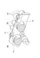
図4は、第1光源ユニット100の分解斜視図である。第1光源ユニット100は、車両用灯具500の配光パターンのうちで比較的狭い中央の領域を集中的に照射するように構成される。第1光源ユニット100は、光源モジュール40、台座50、反射鏡80、およびレンズ90を備える。光源モジュール40は、光源部10、点灯回路30、および金属基板42を有する。光源部10は、内部に発光ダイオード素子14を有しており、受け取る電力に応じて発光する。点灯回路30は、車両用灯具500の外部から受け取る制御信号に応じて、車両用灯具500の外部から受け取る電力に基づいて、光源部10に流れる電流を制御することにより、光源部10を点消灯させる。本発明における搭載基板の一例である金属基板42は、略長方形の金属を絶縁層で覆うことにより形成されており、熱伝導率が高い。また、金属基板42は、点灯回路30および光源部10を同一の面に搭載する。 FIG. 4 is an exploded perspective view of the first
台座50は、光源モジュール40を載置すると共に、反射鏡80およびレンズ90を光源モジュール40に対して固定する。台座50は、金属やセラミック等、樹脂よりも高い熱伝導率を有する材料で形成されるのが好ましい。反射鏡80は、光源部10の発光ダイオード素子14の上方に固定される略ドーム状の部材であり、内側に第1光源ユニット100の光軸を中心軸とした略楕円球面状の反射面を有する。より詳細には、第1光源ユニット100の光軸を含む断面が、光源部10の後方に離間した一点を共通の頂点とした略1/4楕円形状となるように反射面が形成されている。このような形状により、反射鏡80は光源部10が発する光を前方へ向けてレンズ90の光軸寄りに集光反射する。レンズ90は、光源モジュール40側にシェード92を含む。シェード92は、反射鏡80が反射した光の一部を遮蔽あるいは反射することにより、第1光源ユニット100の配光パターンを形成する光線をレンズ90に入射させる。レンズ90は、反射鏡80で反射された光を車両用灯具500の前方に投影する。 The
ここで、金属基板42は、熱伝導率の高い素材で形成されており、点灯回路30および当該点灯回路30が点消灯させる光源部10を同一の面に搭載するので、光源部10が発生する熱を、光源部10および点灯回路30が搭載されている金属基板42の裏面から台座50へ伝導させ、第1光源ユニット100の背面に設けられたヒートシンク56に伝導させることができる。従って、金属基板42は、光源部10が発生した熱を効率良く放散することができる。 Here, the
図5は、光源モジュール40の詳細な構成の一例を示す。図5(a)は、光源モジュール40の上面図である。図5(b)は、光源モジュール40の側面図である。金属基板42は、略長方形の板状体であり、光源部10を一端近傍に搭載し、かつ点灯回路30を他端近傍に搭載する。光源部10は、発光ダイオード素子14の他に、モールド12および放熱基板16を有する。放熱基板16は、モールド12および発光ダイオード素子14を上面に載置し、発光ダイオード素子14が発生した熱を金属基板42へ伝導させる。モールド12は、光を透過する素材により半球状に形成され、発光ダイオード素子14を封止する。 FIG. 5 shows an example of a detailed configuration of the
点灯回路30は、点灯回路部品32、点灯回路部品34、点灯回路部品36、およびコネクタ38を備える。コネクタ38は、光源モジュール40の外部から点灯回路30に供給される電力を受け取る。点灯回路部品32は、発光ダイオード素子14からL1だけ離れた金属基板42上の位置に搭載されており、高さがh1である。点灯回路部品34は、発光ダイオード素子14からL1よりも遠いL2だけ離れた金属基板42上の位置に搭載されており、高さがh1よりも高いh2である。点灯回路部品36は、発光ダイオード素子14からL3だけ離れた金属基板42上の位置に搭載されており、その高さh3は、金属基板42から発光ダイオード素子14までの高さであるh0よりも高い。なお、発光ダイオード素子14と点灯回路部品36との距離L3は、例えば5mm以上であることが好ましい。 The
このように、高さのより低い部品が発光ダイオード素子14のより近くに搭載されるので、発光ダイオード素子14が発生する光の中で点灯回路30によって遮られる割合を少なくすることができる。従って、発光ダイオード素子14が発生する光をより効率良く光源モジュール40の外部へ照射することができる。 In this way, since the component having a lower height is mounted closer to the light emitting
なお、本例において、光源モジュール40は、1個の光源部10を有するが、他の例として、複数の光源部10を有してもよい。また、本例において、光源部10は、1個の発光ダイオード素子14を有するが、他の例として、複数の発光ダイオード素子14を有してもよい。なお、点灯回路部品32は、本発明における第2の部品の一例であり、点灯回路部品34は、本発明における第1の部品の一例であり、点灯回路部品36は、本発明における第3の部品の一例である。 In this example, the
図6は、光源モジュール40の温度分布の一例を示す。光源部10が点灯する場合、光源部10が発生した熱が金属基板42に伝導することにより、光源部10は、金属基板42に、光源部10から離れるほど温度が低くなる、Aに示すような温度分布を形成する。また、点灯回路30が光源部10を点灯させる場合、点灯回路30が有するトランジスタ等が発熱する。そのため、点灯回路30は、金属基板42に、点灯回路30から離れるほど温度が低くなる、Bに示すような温度分布を形成する。これにより、光源部10および点灯回路30は、金属基板42に、Cに示すような温度分布を形成する。 FIG. 6 shows an example of the temperature distribution of the
ここで、光源部10と点灯回路30とが金属基板42上で近接して配置されるとすれば、光源部10が点灯する場合、光源部10の発光ダイオード素子14が発生する熱に加えて、点灯回路30が発生する熱により、光源部10がさらに加熱される場合がある。この場合、外気と光源部10の温度差は、発光ダイオード素子14のみによる温度上昇よりも高くなる。 Here, if the
しかし、本例においは、光源部10および点灯回路30は、光源モジュール40の一端および他端にそれぞれ搭載されるので、点灯回路30が発生する熱が光源部10に伝わる割合が小さい。そのため、光源部10と点灯回路30とが近接して配置される場合に比べて、光源部10の温度上昇が小さくなり、光源部10の外気との温度差は小さくなる。これにより、光源部10と点灯回路30とが近接して配置される場合に比べて、発光ダイオード素子14の放熱効率は高くなる。従って、光源部10のモールド12が黄変等を生じることによる、光源部10の光量の低下を防止することができる。さらに、発光ダイオード素子14が発生した熱が、点灯回路30へ伝わる割合も小さくなるので、温度変化に対する定数の変化の大きい、安価な部品を点灯回路30に用いることができる。 However, in this example, since the
図7は、第1光源ユニット100の光路の一例を示す断面図である。反射鏡80は、金属基板42の光源部10が搭載されている面側に設けられる。反射鏡80の内面に形成された反射面は、レンズ90の光軸を含む断面形状が略楕円形状に形成されており、その離心率が鉛直断面から水平断面へ向けて徐々に大きくなるように設定されている。反射鏡80は、発光ダイオード素子14の発光面上に光学的中心を有する。これにより、反射鏡80は、発光ダイオード素子14が発生する光を金属基板42の側方へ向けて照射する。レンズ90の光軸を含む垂直方向の断面において、レンズ90は、後方側焦点位置F2を反射鏡80の反射面の焦点位置に一致させるようにして配置されている。 FIG. 7 is a cross-sectional view illustrating an example of an optical path of the first
反射鏡80は、F2を通過してレンズ90の下端に入射する光線94の反射点Aよりも後方の反射面で光源部10の光をF2に集光する。この光線94は、第1光源ユニット100の配光パターンのうちの下側境界に投影される。 The reflecting
一方、レンズ90の光軸に沿った光線96は、第1光源ユニット100の配光パターンのうちの上側境界に投影される。レンズ90と一体に設けられたシェード92は、F2から下方に落ち込むエッジが形成されている。これにより、F2を含む焦点面上においてシェード92のエッジと反射鏡80により形成される光学像がレンズ90により反転され前方へ投影される。 On the other hand, the
一方、水平方向において反射鏡80の焦点はF2よりもレンズ90側に設けられている。そしてF2を含むシェード92のエッジは、反射鏡80の像面湾曲、つまり左右方向に於ける焦点面の湾曲に対応して、上面から見た両側が前方へ湾曲して形成されている。従って、反射鏡80の反射によりF2よりも前方のエッジで結像した光学像は、レンズ90によって左右方向に拡大されて反転投影される。 On the other hand, the focal point of the reflecting
ここで、点灯回路部品36は、発光ダイオード素子14が反射鏡80へ照射する光の光路の外側に設けられ、金属基板42から発光ダイオード素子14までの高さよりも、金属基板42からの高さが高い。これにより、点灯回路部品36は、発光ダイオード素子14が反射鏡80へ照射する光を遮らない。そのため、発光ダイオード素子14が発生する光を反射鏡80およびレンズ90を介して、効率良く第1光源ユニット100の外部へ照射することができる。 Here, the
図8は、車両用灯具500の配光パターンの一例を示す。当該配光パターンは、車両用灯具500の前方25mの位置に配置された仮想鉛直スクリーン上に形成される左ロービーム配光パターンである。当該配光パターンは、第1光源ユニット100によって形成される第1配光パターン800と、第2光源ユニット200によって形成される第2配光パターン802および第3配光パターン804と、第3光源ユニット300によって形成される第4配光パターン806との合成配光パターンとして形成される。配光パターンは、その上端に上下方向の明暗境界を定める水平カットラインCL1及び斜めカットラインCL2を有している。 FIG. 8 shows an example of a light distribution pattern of the
水平カットラインCL1は、車両用灯具500の正面(水平軸H−垂直軸Vの交点)に対してやや下方(0.5〜0.6°程度下向き)に設定されている。斜めカットラインCL2は、垂直軸VとCL1の交点から左上方に約15°程度傾斜している。第1配光パターン800のうちの水平カットラインCL1は、シェード92の水平エッジによって形成され、斜めカットラインCL2は、シェード92の傾斜エッジによって形成される。車両用灯具500はこの様な配光パターンにより、車両前方路面における視認性を確保することができる。 The horizontal cut line CL1 is set slightly downward (downward by about 0.5 to 0.6 °) with respect to the front of the vehicle lamp 500 (intersection of the horizontal axis H and the vertical axis V). The oblique cut line CL2 is inclined about 15 ° to the upper left from the intersection of the vertical axes V and CL1. In the first
図9は、車両用灯具500、電源600、および制御信号生成部700の接続の一例を示す。電源600および制御信号生成部700は、車両用灯具500の外部に設けられる。電源600は、例えば車両のバッテリであり、電源ケーブル602および604を介して、車両用灯具500に電力を供給する。制御信号生成部700は、フラットケーブル702を介して、車両用灯具500が有する複数の光源モジュール40a、b、およびcのそれぞれを点消灯させるための制御信号を、車両用灯具500に与える。 FIG. 9 shows an example of the connection of the
車両用灯具500は、保護回路502およびフィルタ回路504をさらに有する。保護回路502は、例えばダイオード素子であり、車両用灯具500に逆電圧が印可された場合に車両用灯具500に電流を流さないことにより、車両用灯具500を保護する。フィルタ回路504は、例えばコイルおよびコンデンサによるπ型回路であり、電源600へ漏れてしまう電力、或いは電源600から供給される電力の高周波成分を除去する。電源600からの電力は、保護回路502およびフィルタ回路504を経由した後、電源ケーブル606および608を介して、光源モジュール40a、b、およびcのそれぞれの点灯回路30へ供給される。1つの光源モジュール40aは、電源ケーブル606および608によって電源600に接続される。光源モジュール40bおよびcは、車両用灯具500内で光源モジュール40aと電源ケーブル606および608を介して並列に接続される。なお、保護回路502およびフィルタ回路504は、車両に設けられる車両用灯具500のソケット内に設けられてもよく、車両用灯具500内に設けられた専用の基板上に搭載されてもよい。 The
フラットケーブル702は、複数の制御ケーブル704a、b、およびcを有する。制御ケーブル704a、b、およびcのそれぞれは、それぞれの光源モジュール40に対応して設けられており、発光ダイオード素子14の点消灯を制御する制御信号を、対応する点灯回路30へ伝送する。また、制御ケーブル704a、b、およびcのそれぞれは、複数の電源ケーブル602、604、606、および608のそれぞれよりも流れる電流が小さい。そのため、制御ケーブル704a、b、およびcのそれぞれは、複数の電源ケーブル602、604、606、および608のそれぞれよりも細い。なお、例えば光源モジュールaおよびbに同一の点消灯をさせる場合には、制御ケーブル704aおよびbを統合させてもよい。即ち、車両用灯具500に接続される制御ケーブルの本数を、光源モジュールの個数よりも少なくしてもよい。 The
ここで、点灯回路30が車両用灯具500の外部にあるとすれば、車両用灯具500には、光源部10に電流を供給するためのケーブルを設ける必要がある。また、複数の光源部10を個別に点消灯させる場合、車両用灯具500は、個別に点消灯させる光源部10の個数分のケーブルが必要になる。さらに、それぞれ光源部10に接続するケーブルは、制御ケーブル704よりも大きな電流が流れるので、制御ケーブル704よりも太いケーブルである必要がある。そのため、車両用灯具500を小型化することが困難な場合がある。しかし、本例において、車両用灯具500には、電源ケーブル602および604の2本のケーブルと、フラットケーブル702とを接続すればよい。従って、車両用灯具500に接続されるケーブルを少なくすることができるので、車両用灯具500を小型化することができる。 Here, if the
図10は、光源モジュール40の構成の他の例を示す。なお、以下に説明する点を除き、図10において、図5と同じ符号を付した構成は、図5における構成と同一又は同様の機能を有するため説明を省略する。光源モジュール40は、サブ基板44をさらに備える。サブ基板44は、金属基板42よりも熱伝導率が小さい素材で形成される。サブ基板44は、点灯回路30を搭載しており、金属基板42における光源部10が搭載される側の面に搭載される。これにより、点灯回路30は、光源部10の発光ダイオード素子14が発生する熱によって加熱されにくい。そのため、温度変化に応じて特性が変化する部品を点灯回路30に用いた場合であっても、点灯回路30は発光ダイオード素子14を適切に点灯させることができる。 FIG. 10 shows another example of the configuration of the
上記説明から明らかなように、本実施形態によれば、小型化することができると共に、発光ダイオード素子14が発生する熱を効率良く放散することができる車両用灯具500を提供することができる。 As is clear from the above description, according to the present embodiment, it is possible to provide a
以上、本発明を実施の形態を用いて説明したが、本発明の技術的範囲は上記実施の形態に記載の範囲には限定されない。上記実施の形態に、多様な変更または改良を加えることが可能であることが当業者に明らかである。その様な変更または改良を加えた形態も本発明の技術的範囲に含まれ得ることが、特許請求の範囲の記載から明らかである。 As mentioned above, although this invention was demonstrated using embodiment, the technical scope of this invention is not limited to the range as described in the said embodiment. It will be apparent to those skilled in the art that various modifications or improvements can be added to the above-described embodiment. It is apparent from the scope of the claims that the embodiments added with such changes or improvements can be included in the technical scope of the present invention.
10 光源部、12 モールド、14 発光ダイオード素子、16 放熱基板、30 点灯回路、32 点灯回路部品、34 点灯回路部品、36 点灯回路部品、38 コネクタ、40 光源モジュール、42 金属基板、44 サブ基板、50 台座、54 ブラケット、56 ヒートシンク、80 反射鏡、90 レンズ、92 シェード、94 光線、96 光線、100 第1光源ユニット、200 第2光源ユニット、300 第3光源ユニット、400 透明カバー、500 車両用灯具、502 保護回路、504 フィルタ回路、600 電源、602 電源ケーブル、604 電源ケーブル、606 電源ケーブル、608 電源ケーブル、700 制御信号生成部、702 フラットケーブル、704 制御ケーブル、800 第1配光パターン、802 第2配光パターン、804 第3配光パターン、806 第4配光パターン DESCRIPTION OF
Claims (3)
Translated fromJapanese光を発生する複数の光源モジュールを備え、
前記複数の光源モジュールのそれぞれは、
半導体発光素子と、
車両用灯具の外部から受け取る制御信号に応じて、前記半導体発光素子に流れる電流を制御することにより、前記半導体発光素子を点消灯させる点灯回路と、
前記車両用灯具の外部にある電源からの電力を前記点灯回路に供給する電源ケーブルと、
前記半導体発光素子の点消灯を制御する制御信号を、前記点灯回路へ伝送する制御ケーブルと、
前記半導体発光素子および前記点灯回路を搭載する搭載基板と
を有し、
前記点灯回路は、
第1の部品と、
第2の部品と
を含み、
前記搭載基板は、前記第1の部品および前記第2の部品を搭載し、
前記第2の部品は、前記第1の部品よりも前記搭載基板からの高さが低く、前記第1の部品よりも前記半導体発光素子の近くに搭載される車両用灯具。A vehicular lamp used in a vehicle,
A plurality of light source modules for generating light;
Each of the plurality of light source modules is
A semiconductor light emitting device;
A lighting circuit for turning on and off the semiconductor light emitting element by controlling a current flowing through the semiconductor light emitting elementin response to a control signal received from the outside of the vehicle lamp ;
A power cable for supplying power from a power source external to the vehicle lamp to the lighting circuit;
A control cable for transmitting a control signal for controlling turning on / off of the semiconductor light emitting element to the lighting circuit;
A mounting substrate on which the semiconductor light emitting element and the lighting circuit are mounted;
The lighting circuit is
A first part;
With the second part
Including
The mounting board mounts the first component and the second component;
The second component is a vehicular lampthat is lower in height from the mounting substrate than the first component and is mounted closer to the semiconductor light emitting element than the first component .
前記搭載基板よりも熱伝導率が小さい素材で形成され、前記点灯回路を搭載し、前記搭載基板における前記半導体発光素子が搭載されている側の面に搭載されるサブ基板をさらに有する請求項1に記載の車両用灯具。Each of the plurality of light source modules is
The formed by mounting having a lower thermal conductivity than the substrate material, mounting the lighting circuit,according to claim 1, further comprising a sub-substrate to be mounted on the surface on the side where the semiconductor light emitting device in the mounting substrate is mounted The vehicle lampas described in 2.
前記点灯回路は、前記搭載基板に搭載され、前記搭載基板から前記半導体発光素子までの高さよりも、前記搭載基板からの高さが高く、前記半導体発光素子が前記反射鏡へ照射する光の光路の外側に設けられる第3の部品を含む請求項1に記載の車両用灯具。A reflective mirror that is provided on a surface side of the mounting substrate on which the semiconductor light emitting element is provided and reflects light generated by the semiconductor light emitting element;
The lighting circuit is mounted on the mounting substrate, and has a height higher from the mounting substrate than a height from the mounting substrate to the semiconductor light emitting element, and an optical path of light that the semiconductor light emitting element irradiates the reflecting mirror The vehicular lamp accordingto claim 1, further comprising a third part provided outside of the vehicle.
Priority Applications (1)
| Application Number | Priority Date | Filing Date | Title |
|---|---|---|---|
| JP2008205428AJP4523055B2 (en) | 2008-08-08 | 2008-08-08 | Light source module and vehicle lamp |
Applications Claiming Priority (1)
| Application Number | Priority Date | Filing Date | Title |
|---|---|---|---|
| JP2008205428AJP4523055B2 (en) | 2008-08-08 | 2008-08-08 | Light source module and vehicle lamp |
Related Parent Applications (1)
| Application Number | Title | Priority Date | Filing Date |
|---|---|---|---|
| JP2004071587ADivisionJP4373822B2 (en) | 2004-03-12 | 2004-03-12 | Light source module and vehicle lamp |
Publications (2)
| Publication Number | Publication Date |
|---|---|
| JP2008262937A JP2008262937A (en) | 2008-10-30 |
| JP4523055B2true JP4523055B2 (en) | 2010-08-11 |
Family
ID=39985219
Family Applications (1)
| Application Number | Title | Priority Date | Filing Date |
|---|---|---|---|
| JP2008205428AExpired - Fee RelatedJP4523055B2 (en) | 2008-08-08 | 2008-08-08 | Light source module and vehicle lamp |
Country Status (1)
| Country | Link |
|---|---|
| JP (1) | JP4523055B2 (en) |
Cited By (1)
| Publication number | Priority date | Publication date | Assignee | Title |
|---|---|---|---|---|
| US8939627B2 (en) | 2011-07-29 | 2015-01-27 | Stanley Electric Co., Ltd. | Vehicle lighting unit |
Families Citing this family (14)
| Publication number | Priority date | Publication date | Assignee | Title |
|---|---|---|---|---|
| EP2474778A1 (en) | 2009-09-03 | 2012-07-11 | Koito Manufacturing Co., Ltd. | Vehicle headlight |
| US8998463B2 (en) | 2009-09-03 | 2015-04-07 | Koito Manufacturing Co., Ltd. | Light-emitting apparatus and automotive headlamps |
| JP5390372B2 (en)* | 2009-12-25 | 2014-01-15 | 株式会社小糸製作所 | Light source unit and vehicle lamp |
| JP5697924B2 (en)* | 2010-08-26 | 2015-04-08 | 株式会社小糸製作所 | Light emitting device |
| JP5706702B2 (en)* | 2011-02-03 | 2015-04-22 | 株式会社小糸製作所 | Vehicle headlamp |
| JP2013062068A (en)* | 2011-09-12 | 2013-04-04 | Denso Corp | Lamp fitting for vehicle |
| JP5690764B2 (en)* | 2012-03-06 | 2015-03-25 | 株式会社ホンダアクセス | Lighting device |
| US20150219300A1 (en)* | 2012-08-28 | 2015-08-06 | Mitsubishi Electric Corporation | Light source for head light and head light |
| JP6116935B2 (en)* | 2013-02-28 | 2017-04-19 | 本田技研工業株式会社 | Motorcycle headlamp device |
| EP3048360B1 (en) | 2013-08-23 | 2018-05-23 | Koito Manufacturing Co., Ltd. | Lamp device for vehicle and lighting device for vehicle |
| JP2015159020A (en)* | 2014-02-24 | 2015-09-03 | アイリスオーヤマ株式会社 | LED lighting device |
| JP6508924B2 (en)* | 2014-12-01 | 2019-05-08 | 株式会社小糸製作所 | Vehicle lamp |
| JP6622557B2 (en)* | 2015-10-23 | 2019-12-18 | 本田技研工業株式会社 | Vehicle headlamp |
| JP7414832B2 (en)* | 2019-08-27 | 2024-01-16 | 株式会社小糸製作所 | Vehicle lights |
Family Cites Families (6)
| Publication number | Priority date | Publication date | Assignee | Title |
|---|---|---|---|---|
| JPH0545811U (en)* | 1991-11-15 | 1993-06-18 | 株式会社小糸製作所 | Vehicle marker light |
| JP3249028B2 (en)* | 1995-03-30 | 2002-01-21 | 株式会社小糸製作所 | Fender marker |
| JPH10208515A (en)* | 1997-01-23 | 1998-08-07 | Koito Mfg Co Ltd | Lighting fixture for vehicle |
| JP2002314136A (en)* | 2001-04-09 | 2002-10-25 | Toyoda Gosei Co Ltd | Semiconductor light emitting device |
| JP3990132B2 (en)* | 2001-10-04 | 2007-10-10 | 株式会社小糸製作所 | Vehicle lamp |
| JP4005377B2 (en)* | 2002-01-31 | 2007-11-07 | 本田技研工業株式会社 | Vehicle taillight |
- 2008
- 2008-08-08JPJP2008205428Apatent/JP4523055B2/ennot_activeExpired - Fee Related
Cited By (1)
| Publication number | Priority date | Publication date | Assignee | Title |
|---|---|---|---|---|
| US8939627B2 (en) | 2011-07-29 | 2015-01-27 | Stanley Electric Co., Ltd. | Vehicle lighting unit |
Also Published As
| Publication number | Publication date |
|---|---|
| JP2008262937A (en) | 2008-10-30 |
Similar Documents
| Publication | Publication Date | Title |
|---|---|---|
| JP4523055B2 (en) | Light source module and vehicle lamp | |
| JP4373822B2 (en) | Light source module and vehicle lamp | |
| JP5652996B2 (en) | Vehicle lighting | |
| US7165871B2 (en) | Lamp | |
| CN109937321B (en) | Front light device | |
| JP4343720B2 (en) | Lamp | |
| US7281832B2 (en) | Vehicular lamp | |
| JP6648430B2 (en) | Vehicle lighting | |
| CN103727475B (en) | Vehicular headlamp | |
| JP4593661B2 (en) | Vehicle lighting | |
| US7318662B2 (en) | Vehicular headlamp | |
| WO2017104679A1 (en) | Vehicle lamp | |
| JP2005209538A (en) | Lamp | |
| JP5711558B2 (en) | Optical unit and vehicle lamp | |
| JP2009163921A (en) | Vehicle headlamp | |
| JP4295126B2 (en) | Lamp | |
| JP2020013697A (en) | Vehicular lighting fixture | |
| US10883696B2 (en) | Lighting tool for vehicle | |
| JP7108359B2 (en) | vehicle lamp | |
| JP5591097B2 (en) | Optical unit | |
| JP7101547B2 (en) | Vehicle headlights | |
| JP2005209537A (en) | Lamp | |
| WO2025002560A1 (en) | Light module and lighting device for a motor vehicle | |
| JP2016066507A (en) | Vehicle lamp fitting |
Legal Events
| Date | Code | Title | Description |
|---|---|---|---|
| A521 | Request for written amendment filed | Free format text:JAPANESE INTERMEDIATE CODE: A523 Effective date:20080808 | |
| A621 | Written request for application examination | Free format text:JAPANESE INTERMEDIATE CODE: A621 Effective date:20080808 | |
| A977 | Report on retrieval | Free format text:JAPANESE INTERMEDIATE CODE: A971007 Effective date:20100108 | |
| TRDD | Decision of grant or rejection written | ||
| A01 | Written decision to grant a patent or to grant a registration (utility model) | Free format text:JAPANESE INTERMEDIATE CODE: A01 Effective date:20100525 | |
| A01 | Written decision to grant a patent or to grant a registration (utility model) | Free format text:JAPANESE INTERMEDIATE CODE: A01 | |
| A61 | First payment of annual fees (during grant procedure) | Free format text:JAPANESE INTERMEDIATE CODE: A61 Effective date:20100526 | |
| R150 | Certificate of patent or registration of utility model | Ref document number:4523055 Country of ref document:JP Free format text:JAPANESE INTERMEDIATE CODE: R150 Free format text:JAPANESE INTERMEDIATE CODE: R150 | |
| FPAY | Renewal fee payment (event date is renewal date of database) | Free format text:PAYMENT UNTIL: 20130604 Year of fee payment:3 | |
| LAPS | Cancellation because of no payment of annual fees |