JP4521858B2 - Image processing device - Google Patents
Image processing deviceDownload PDFInfo
- Publication number
- JP4521858B2 JP4521858B2JP2004034514AJP2004034514AJP4521858B2JP 4521858 B2JP4521858 B2JP 4521858B2JP 2004034514 AJP2004034514 AJP 2004034514AJP 2004034514 AJP2004034514 AJP 2004034514AJP 4521858 B2JP4521858 B2JP 4521858B2
- Authority
- JP
- Japan
- Prior art keywords
- imaging
- image processing
- processing apparatus
- imaging range
- solid
- Prior art date
- Legal status (The legal status is an assumption and is not a legal conclusion. Google has not performed a legal analysis and makes no representation as to the accuracy of the status listed.)
- Expired - Fee Related
Links
Images


Classifications
- G—PHYSICS
- G01—MEASURING; TESTING
- G01N—INVESTIGATING OR ANALYSING MATERIALS BY DETERMINING THEIR CHEMICAL OR PHYSICAL PROPERTIES
- G01N21/00—Investigating or analysing materials by the use of optical means, i.e. using sub-millimetre waves, infrared, visible or ultraviolet light
- G01N21/84—Systems specially adapted for particular applications
- G01N21/88—Investigating the presence of flaws or contamination
- G01N21/95—Investigating the presence of flaws or contamination characterised by the material or shape of the object to be examined
- G01N21/9501—Semiconductor wafers
- G—PHYSICS
- G01—MEASURING; TESTING
- G01N—INVESTIGATING OR ANALYSING MATERIALS BY DETERMINING THEIR CHEMICAL OR PHYSICAL PROPERTIES
- G01N21/00—Investigating or analysing materials by the use of optical means, i.e. using sub-millimetre waves, infrared, visible or ultraviolet light
- G01N21/84—Systems specially adapted for particular applications
- G01N21/88—Investigating the presence of flaws or contamination
- G01N21/95—Investigating the presence of flaws or contamination characterised by the material or shape of the object to be examined
- G01N21/956—Inspecting patterns on the surface of objects
Landscapes
- General Health & Medical Sciences (AREA)
- General Physics & Mathematics (AREA)
- Life Sciences & Earth Sciences (AREA)
- Chemical & Material Sciences (AREA)
- Analytical Chemistry (AREA)
- Biochemistry (AREA)
- Health & Medical Sciences (AREA)
- Immunology (AREA)
- Physics & Mathematics (AREA)
- Pathology (AREA)
- Studio Devices (AREA)
- Investigating Materials By The Use Of Optical Means Adapted For Particular Applications (AREA)
- Image Analysis (AREA)
- Image Processing (AREA)
- Closed-Circuit Television Systems (AREA)
Description
Translated fromJapanese本発明は画像処理装置に関する。 The present invention relates to an image processing apparatus.
IC(集積回路)、電子部品などの様々な製品の製造過程や製造後の検査、例えば、製品のサイズの計測、傷や汚れの有無などの検査に画像処理装置が用いられている(例えば、特許文献1)。 An image processing apparatus is used in the manufacturing process of various products such as IC (integrated circuit) and electronic parts and inspection after manufacturing, for example, measurement of product size, inspection of presence or absence of scratches and dirt (for example, Patent Document 1).
図1に示すように、この種の画像処理装置1は、CCDなどの固体撮像素子を含むカメラ2と、画像処理装置本体3と、画像処理装置本体3による検査又は計測結果を表示するためのモニタ4と、カメラ2と画像処理装置本体3、画像処理装置本体3とモニタ4とを、夫々、離脱可能に接続するケーブル5、6と、モニタ4とを含むのが通例であり、従来の画像処理装置1にあっては、固体撮像素子の全視野領域(CCD有効画素領域)7やその周縁部分を除く中央領域を撮像範囲8(図2)として固定し、この撮像範囲8の画像(撮像画像)をカメラ2から画像処理装置本体3に転送して画像処理を行うようになっていた。
上述したことから分かるように、従来の画像処理装置1にあっては、カメラ2の固体撮像素子の全視野領域(CCD有効画素領域)7の全て又は中央領域7に撮像範囲8を固定して撮像画像を画像処理装置本体3に転送するようになっているが、従来の典型例である中央領域7に撮像範囲8を固定したものにあっては、これが主に画像処理装置本体3のメモリ容量やモニタ4の表示制限などの理由によるものであるにしても、カメラ2の固体撮像素子の全視野領域(CCD有効画素領域)6を有効活用する観点からすると、全視野領域7に製品つまり検査対象物が入っているにもかかわらず、撮像範囲8から外れている場合には、検査対象物又はカメラ2を相対移動させた後に再度の検査又は計測を行う必要があった。 As can be seen from the above, in the conventional
また、検査又は計測の精度を上げるために拡大して(倍率を変えて)撮像した場合、製品が撮像範囲8内に入らない場合もあり、このような場合にあっても、検査対象物又はカメラ2を相対移動させた後に再度の検査又は計測を行う必要があった。 In addition, when the image is enlarged (changed in magnification) to increase the accuracy of the inspection or measurement, the product may not enter the
近時のカメラ2は、その固体撮像画素の数が、例えば、200万画素、400万画素、700万画素というように年々が高画素化の傾向にあるが、画像処理装置本体3と組み合わせて使用するカメラを最新式の高画素数のカメラに置換したときには、カメラの置換により全視野領域7が拡大しているにも関わらず、実際に画像処理する撮像範囲8は固定であることから、結局のところ、最新式のカメラを導入した価値が無くなってしまうという問題がある。 The
また、仮に最新式の高画素数カメラの全視野領域7を活用する能力を備えた画像処理装置本体3を作ったとしても、画像処理装置本体3が膨大なメモリ容量を具備する必要があるだけでなく、カメラ2から画像処理装置本体3へ撮像画像を転送するのに時間を要し、その結果、高速に画像処理することができないという別の観点からの問題が発生する。 Further, even if the image processing apparatus
そこで、本発明の目的は、カメラから画像処理装置本体への撮像画像の転送速度を低下させることなく、カメラの固体撮像素子の全視野領域を有効活用することのできる画像処理装置を提供することにある。 Accordingly, an object of the present invention is to provide an image processing apparatus that can effectively utilize the entire visual field region of the solid-state image sensor of the camera without reducing the transfer speed of the captured image from the camera to the image processing apparatus main body. It is in.
本発明の他の目的は、カメラと検査対象物との相対移動を不要にしつつ、カメラの固体撮像素子の全視野領域を有効活用して検査又は計測の精度を高めることのできる画像処理装置を提供することにある。 Another object of the present invention is to provide an image processing apparatus that can increase the accuracy of inspection or measurement by effectively utilizing the entire field of view of the solid-state imaging device of the camera while eliminating the relative movement between the camera and the inspection object. It is to provide.
本発明の更なる目的は、年々高画素化しているカメラを組み込んで画像処理装置を構築したとしても、実用上満足のいく処理速度で且つカメラの固体撮像素子の全視野領域を有効活用して検査又は計測の精度を高めることのできる画像処理装置を提供することにある。 A further object of the present invention is to make effective use of the entire field of view of the solid-state image sensor of the camera at a processing speed that is practically satisfactory even when an image processing apparatus is built by incorporating a camera with an increasing number of pixels year by year. An object of the present invention is to provide an image processing apparatus capable of increasing the accuracy of inspection or measurement.
本発明の更なる目的は、検査又は計測の精度を上げるために拡大して撮像した場合であっても、カメラの固体撮像素子の全視野領域を有効活用して検査又は計測することのできる画像処理装置を提供することにある。 A further object of the present invention is an image that can be inspected or measured by effectively utilizing the entire field of view of the solid-state image sensor of the camera, even when the image is magnified to improve the accuracy of inspection or measurement. It is to provide a processing apparatus.
上述した技術的課題を達成すべく、本発明によれば、
検査対象物を撮像する固体撮像素子カメラと、該カメラから撮像画像を受け取って画像処理する画像処理装置本体と、該画像処理装置本体による検査又は測定結果を表示するためのモニタとを有する画像処理装置において、
前記画像処理装置本体が、
前記固体撮像素子カメラの全視野領域の一部を撮像範囲として設定する撮像範囲設定手段と、
撮像範囲設定手段により設定された撮像範囲に対応する撮像条件を設定する撮像条件設定手段と、
前記撮像範囲設定手段によって設定された前記撮像範囲と、前記撮像条件設定手段によって設定された前記撮像条件とを記憶する記憶手段と、
前記記憶手段に記憶された前記撮像範囲と当該撮像範囲に対応して設定された前記撮像条件とを読み込んで、前記撮像範囲及び前記撮像条件に関する信号を前記固体撮像素子カメラに送信する送信手段と、
前記撮像範囲に対応して設定された前記撮像条件に基づいて前記固体撮像素子カメラが撮像した前記撮像範囲の撮像画像信号を受信する受信手段とを有し、
該受信手段により受け取った前記撮像画像信号に基づいて画像処理を行うと共に、
前記撮像範囲設定手段は、前記固体撮像素子カメラの全視野領域に対して、夫々異なる複数の撮像範囲が設定可能であり、
前記撮像条件設定手段は、前記撮像範囲設定手段によって設定された各々の撮像範囲に対応した異なる撮像条件が設定可能であることを特徴とする画像処理装置を提供することにより達成される。To achieve the technical object mentioned above, accordingto this onsetAkira,
Image processing having a solid-state imaging device camera for imaging an inspection object, an image processing apparatus main body for receiving a captured image from the camera and processing the image, and a monitor for displaying an inspection or measurement result by the image processing apparatus main body In the device
The image processing apparatus main body is
Imaging range setting means for setting a part of the entire visual field area of the solid-state imaging device camera as an imaging range;
Imaging condition setting means for setting imaging conditions corresponding to the imaging range set by the imaging range setting means;
Storage meansfor storing the imaging range set by the imaging range setting means and the imaging conditions set by the imaging condition setting means ;
Loadingand said imaging condition set corresponding to the imaging rangeand the imaging range stored in the storage means, transmitting means for transmitting a signal related tothe imaging rangeand the imaging condition to the solid-state imaging device camera ,
And a receiving means for receiving an image signalof the imaging range in which the solid-state imaging device camera is captured on the basis of the imaging condition set corresponding tothe imaging range,
While performing image processing based on the captured image signal received by the receiving means,
The imaging range setting means can set a plurality of different imaging ranges for the entire visual field region of the solid-state imaging device camera,
The imaging condition setting means is achieved by providing an image processing apparatus characterizedin that different imaging conditions corresponding to each imaging range set by the imaging range setting means can be set .
すなわち、本発明による画像処理装置によれば、従来では固定的であった撮像範囲をユーザが任意に設定することが可能であり、この結果、高画素数カメラを組み込んで画像処理装置を構築したとしてもカメラから画像処理装置本体への撮像画像の転送速度を低下させることはなく、また、カメラの固体撮像素子の全視野領域を有効活用した撮像範囲を設定することも可能である。したがって、カメラと検査対象物との相対移動は不要であり、検査又は計測の精度を高めることができる。したがって、高画素数カメラを使用して撮像しても、実用上満足のいく処理速度で且つカメラの固体撮像素子の全視野領域を有効活用して検査又は計測の精度を高めることができる。Namely, according to the image processing apparatus in accordancewith the present onsetbright, the conventional is capable user an imaging range was fixed arbitrarily set, as a result, the image processing apparatus incorporates a high pixel number Camera Even if it is constructed, the transfer speed of the picked-up image from the camera to the image processing apparatus main body is not lowered, and it is also possible to set an image pickup range that effectively uses the entire visual field area of the solid-state image pickup device of the camera. Therefore, relative movement between the camera and the inspection object is unnecessary, and the accuracy of inspection or measurement can be improved. Therefore, even if the imaging using high pixel count camerascan increase the accuracy of the effective use to test or measure the entire viewing area of and the camera of the solid-state imaging device at a processing rate go practically satisfactory.
本発明に従う画像処理装置にあっては、カメラと画像処理装置本体とがケーブルで接続された画像処理装置であってもよく、また、カメラと画像処理装置本体とが一体化された画像処理装置であってもよい。また、撮像範囲の設定は、画像処理装置本体に接続した外部機器を使って行うようにしてもよく、或いは、画像処理装置本体で撮像範囲の設定ができるようにしてもよい。外部機器を使って画像範囲の設定を行うときには、画像処理装置本体で画像処理中に画像範囲の設定を行うことができるという利点がある。 The image processing apparatus according to the present invention may be an image processing apparatus in which the camera and the image processing apparatus main body are connected by a cable, or the image processing apparatus in which the camera and the image processing apparatus main body are integrated. It may be. The imaging range may be set using an external device connected to the image processing apparatus main body, or the imaging range may be set on the image processing apparatus main body. When setting an image range using an external device, there is an advantage that the image range can be set during image processing in the image processing apparatus main body.
以下に、図3〜図10を参照して、本発明の好ましい実施例を説明する。 Hereinafter, a preferred embodiment of the present invention will be described with reference to FIGS.
実施例の画像処理装置10は、図3に示すように、従来一般的な構成、つまりCCDカメラ11、画像処理装置本体12、モニタ13、これらを接続するケーブル14、15を有し、CCDカメラ11、画像処理装置本体12、モニタ13はケーブル14、15を外すことにより分離可能である。CCDカメラ11は、製品ライン16の所定の検査ステーション17に固定的に設置され、製品ライン16を所定のタクトで流れる検査対象物(製品)Wは、検査ステーション17の規定された場所で一時的に移動を停止した状態でカメラ11による検査対象物Wの撮像が行われる。 As shown in FIG. 3, the
画像処理装置本体12内のメモリ18には、図4に例示するように、ユーザが任意に設定した撮像モード、具体的には、撮像範囲、撮像条件が記憶されており、CCDカメラ11による同一の検査対象物の複数回の撮像の各撮像の際に、メモリ18に記憶されている撮像モードに従ってCCDカメラ11の撮像モードの設定を変更することができる。 As illustrated in FIG. 4, the
図4に例示の撮像モードの設定画面について説明すると、ユーザは、第1〜第4グループGr1〜Gr4に分けて撮像モードの登録を行うようになっており、各グループ毎に、撮像範囲と、カメラの撮像条件を任意に設定することができ、この設定作業は、モニタ13を見ながら画像処理装置本体12で行うようにしてもよく、或いは、前記画像処理装置本体12に接続した外部機器、例えばパーソナルコンピュータにより行うようにしてもよい。外部機器により撮像範囲、撮像条件を設定する場合には、画像処理装置本体12の画像処理中に設定処理を行うことができ、設定された撮像範囲、撮像条件はメモリ18に記憶される。 The imaging mode setting screen illustrated in FIG. 4 will be described. The user registers the imaging mode separately for the first to fourth groups Gr1 to Gr4. For each group, the imaging range and Imaging conditions of the camera can be arbitrarily set, and this setting operation may be performed by the image processing apparatus
画像処理装置本体12が、撮像範囲、撮像条件を設定する手段を備えているときには、撮像範囲、撮像条件を設定するための設定モードと、カメラの撮像及び画像処理を行う運用モードとに切換可能であるのが好ましい。設定モードを使ってユーザが登録した撮像モードつまり撮像範囲、撮像条件はメモリ18に記憶され、運用モードでは、メモリ18に記憶されている撮像モードを読み込んで、この読み込んだ撮像範囲及び撮像条件に関する信号が画像処理装置本体12からCCDカメラ11に供給されてCCDカメラ11の設定が行われる。 When the image processing apparatus
この撮像モードの設定を、図4及び図5を参照して具体的に説明すると、図4の第1グループGr1に見られる撮像範囲「左上」は、CCDカメラ11のCCD有効画素領域20に対してその左上部分を第1撮像範囲21aとして登録することを意味している。同様に、第2グループGr2に見られる撮像範囲「右上」は、CCD有効画素領域20に対してその右上部分を第2撮像範囲21bとして登録することを意味している。設定モードで、このようにCCD有効画素領域20内の任意の部分を「左上」や「右上」などで指定したときに、その範囲をモニタ4に表示するのが好ましく、モニタ4で確認した後に決定することで、メモリ18に記憶させるのがよい。このような撮像範囲の登録の方法は、その前段階で、撮像範囲の大きさを予めユーザによって設定できるのが好ましい。 The setting of the imaging mode will be described in detail with reference to FIGS. 4 and 5. The imaging range “upper left” seen in the
換言すれば、図4に例示の登録例では、ユーザが予め設定登録した撮像範囲21の大きさを前提に、この撮像範囲21をどこに設定するかを「左上」などで選択することで撮像範囲を指示し、これを決定することのよりメモリ18に記憶される。また、図4の撮像条件の例えばシャッタ1/500はシャッタスピードであり、また、例えばゲイン5やゲイン6はCCD出力信号の増幅幅の程度を意味している。撮像範囲21の配置位置の設定では、CCD有効画素領域20の左上角隅を原点とした座標X(+)、Y(+)で指示して、これを登録するようにしてもよい。また、例えば撮像条件のシャッタスピードは、明るさ(露光時間)を変化させるものであるが、撮像条件として登録可能なパラメータつまり設定登録可能な撮像条件としては、ズーム(倍率)、走査方式、絞り、照明などを含む。 In other words, in the registration example illustrated in FIG. 4, on the assumption of the size of the imaging range 21 set and registered in advance by the user, the imaging range is selected by selecting “upper left” or the like where to set the imaging range 21. Is stored in the
グループGr1〜Gr4の数は制限されるものではなく単なる例示にすぎないが、第1〜第4グループGr1〜Gr4は、一つの検査対象物に対するシャッタ回数(トリガ番号)に対応している。第1グループGr1は、同一の検査対象物に対して、第1番目のトリガつまり第1回目のシャッタを実質的に意味し、第2グループGr2は第2番目のトリガを実質的に意味し、第3グループGr3は第3番目のトリガを実質的に意味し、第4グループGr4は第4番目のトリガを実質的に意味する。 The number of groups Gr1 to Gr4 is not limited and is merely an example, but the first to fourth groups Gr1 to Gr4 correspond to the number of shutters (trigger number) for one inspection object. The first group Gr1 substantially means the first trigger, that is, the first shutter, and the second group Gr2 substantially means the second trigger for the same inspection object. The third group Gr3 substantially means the third trigger, and the fourth group Gr4 substantially means the fourth trigger.
検査対象物のカメラ11による撮像から画像処理装置本体12に撮像画像を取り込んで画像処理する手順の一例を図6のフローチャートを参照して説明する。 An example of a procedure for capturing a captured image from the imaging of the inspection object by the camera 11 to the image processing apparatus
検査対象物Wが検査ステーション17の所定位置に停止すると、これに同期して、外部から供給される処理開始信号を画像処理装置本体12を受けることにより処理が開始される。ステップS1では、第1グループGr1として登録された撮像範囲及び撮像条件がメモリ18から読み込まれて、この第1グループGr1の撮像範囲及び撮像条件に関する信号が画像処理装置12からCCDカメラ11に供給され、これによりCCDカメラ11の設定が行われ、第1グループGr1の撮像条件に従ってCCDカメラ11の撮像が実行される(ステップS2)。 When the inspection object W stops at a predetermined position of the
次のステップS3では、CCDカメラ11が撮像した生画像(全視野領域20の画像)のうち第1グループGr1の撮像範囲の画像(撮像画像)がCCDカメラ11から画像処理装置本体12に送られて、これを画像処理装置本体12が受け取って、ステップS4で、画像処理装置本体12は従来と同様の画像処理を行う。 In the next step S3, the image (captured image) of the imaging range of the first group Gr1 among the raw images (image of the entire visual field 20) captured by the CCD camera 11 is sent from the CCD camera 11 to the image processing apparatus
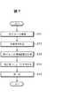
ここに、ステップS4の画像処理は、画像のx軸、y軸及び回転θに関する位置補正(x,y,θ)を含む、所望の検査又は計測(例えば、サイズ、傷の有無、個数、エッジ検出)に必要な処理を意味するものであるが、この位置補正を含む画像処理は従来から既知であるので詳しい説明は省略するが、位置補正に関し、例えば図7を参照して手順を説明すると、ステップS11で第1グループGr1の撮像を行った後、生画像はカメラ11から画像処理装置本体12に転送され(ステップS12)、画像処理装置本体12で、第1グループで設定されている撮像範囲の計測が行われ(ステップS13)、この計測に基づいて補正量(x,y,θ)が演算され、補正量(x,y,θ)は画像処理装置本体12内のメモリに保存され、この補正量(x,y,θ)は、第2グループ以降の画像処理に含まれる前処理(位置補正)に使用される。 Here, the image processing in step S4 includes desired inspection or measurement (for example, size, presence / absence of scratches, number, edge) including position correction (x, y, θ) with respect to the x-axis, y-axis, and rotation θ of the image. The image processing including the position correction is known in the art and will not be described in detail. However, regarding the position correction, for example, the procedure will be described with reference to FIG. After capturing the first group Gr1 in step S11, the raw image is transferred from the camera 11 to the image processing apparatus main body 12 (step S12), and the image processing apparatus
第1グループの撮像及び画像処理が完了すると、ステップS1に戻って第2グループGr2として登録された撮像範囲及び撮像条件がメモリ18から読み込まれ、この第2グループGr2の撮像範囲及び撮像条件に関する信号が画像処理装置本体12からCCDカメラ11に供給され、これによりCCDカメラ11が設定され、第2グループGr2の撮像条件に従ってCCDカメラ11の撮像が実行される(ステップS2)。ついで、次のステップS3では、CCDカメラ11が撮像した生画像(全視野領域20の画像)のうち第2グループGr2の撮像範囲の画像(撮像画像)がCCDカメラ11から画像処理装置本体12に送られて、これを画像処理装置本体12が受け取って、ステップS4で、画像処理装置本体12は従来と同様の画像処理を行う。 When the imaging and image processing of the first group are completed, the process returns to step S1 and the imaging range and imaging conditions registered as the second group Gr2 are read from the
第2グループGr2の撮像及び画像処理が完了すると、ステップS1に再び戻って、第3グループGr3として登録された撮像範囲及び撮像条件がメモリ18から読み込まれ、この第3グループGr3の撮像範囲及び撮像条件に関する信号が画像処理装置本体12からCCDカメラ11に供給され、これによりCCDカメラ11が設定され、この第3グループGr3撮像条件に従ってCCDカメラ11の撮像が実行される(ステップS2)。ついで、次のステップS3では、CCDカメラ11が撮像した生画像(全視野領域20の画像)のうち第3グループGr3の撮像範囲の画像(撮像画像)がCCDカメラ11から画像処理装置本体12に送られて、これを画像処理装置本体12が受け取って、ステップS4で、画像処理装置本体12は従来と同様の画像処理を行う。 When the imaging and image processing of the second group Gr2 are completed, the process returns to step S1, and the imaging range and imaging conditions registered as the third group Gr3 are read from the
第3グループGr3の撮像及び画像処理が完了すると、ステップS1に再び戻って、第4グループGr4として登録された撮像範囲及び撮像条件がメモリ18から読み込まれ、この第4グループGr4の撮像範囲及び撮像条件に関する信号が画像処理装置本体12からCCDカメラ11に供給され、これによりCCDカメラ11が設定され、この第4グループGr4の撮像条件に従ってCCDカメラ11の撮像が実行される(ステップS2)。ついで、次のステップS3では、CCDカメラ11が撮像した生画像(全視野領域20の画像)のうち第4グループGr4の撮像範囲の画像(撮像画像)がCCDカメラ11から画像処理装置本体12に送られて、これを画像処理装置本体12が受け取って、ステップS4で、画像処理装置本体12は従来と同様の画像処理を行う。 When imaging and image processing of the third group Gr3 are completed, the process returns to step S1, and the imaging range and imaging conditions registered as the fourth group Gr4 are read from the
第4グループGr4の撮像及び画像処理が完了すると、ステップS5で全グループの処理が完了したとして(ステップS5)、同一検査対象物の検査又は計測が完了し、次の対象物が検査ステーションに到来するまで待機状態となる。 When the imaging and image processing of the fourth group Gr4 are completed, the processing of all groups is completed in step S5 (step S5), and the inspection or measurement of the same inspection object is completed, and the next object arrives at the inspection station. It will be in a standby state until
例えば、図5に見られるように、撮像範囲21aと21bとが互い重なり合った部分21cの画像処理に関し、複数回取り込んだ画像を1枚の画像として処理する場合に互いに重なり合った部分21cの処理が必要となるが、この重なり合った部分21cを平均化することにより画像処理してもよく、或いは、画像の取込みに優先順位を付けて順位の高い画像により画像処理してもよく、或いは、取り込んだ画像に重み付けして画像処理を行うようにしてもよい。 For example, as shown in FIG. 5, regarding the image processing of the
また、複数の画像処理(例えば第1グループGr1の画像処理から、順次、後続の画像処理)を行う場合、各段階での画像処理結果に応じて、その次の撮像範囲及び撮像条件を選択的に変更するようにしてもよい。例えば、第1グループGr1の画像処理で公差の検査を行った結果、公差の範囲内(OK)の場合には、別の場所の面積検査を行うように撮像範囲及び撮像条件の設定信号をカメラ11に送信して、この撮像範囲及び撮像条件の設定信号に従って撮像を行う。逆に、公差の範囲外(NO)の場合には、第1グループGr1の撮像範囲でゲインを変更する設定信号をカメラ11に送信して、この撮像範囲及び撮像条件の設定信号に従って撮像を行って第1グループGr1の撮像範囲の再検査を行うようにしてもよい。 Further, when performing a plurality of image processing (for example, image processing of the first group Gr1 and subsequent image processing sequentially), the next imaging range and imaging conditions are selectively selected according to the image processing result at each stage. You may make it change to. For example, when the tolerance inspection is performed in the image processing of the first group Gr1, if the tolerance is within the range (OK), the setting signal of the imaging range and the imaging condition is transmitted to the camera so that the area inspection of another place is performed. 11 to perform imaging according to the setting signal of the imaging range and imaging conditions. Conversely, if the tolerance is out of range (NO), a setting signal for changing the gain in the imaging range of the first group Gr1 is transmitted to the camera 11, and imaging is performed according to the imaging range and imaging condition setting signal. Thus, the reexamination of the imaging range of the first group Gr1 may be performed.
他の例としては、例えば第1の撮像範囲及び撮像条件の下での撮像画像の画像処理で形状マッチングの検査を行った結果、第1テンプレートと一致した場合には、これに続いて同じ撮像範囲での公差の検査を行い、また、第2テンプレートと一致した場合には、これに続いて同じ撮像範囲で線傷検査を行い、第1、第2のテンプレートのいずれとも一致しなかった場合には、後続の検査を実行しないというように、画像処理結果に応じて後続の検査を変更するようにしてもよい。 As another example, for example, when the shape matching inspection is performed in the image processing of the captured image under the first imaging range and the imaging condition, and the result matches the first template, the same imaging is subsequently performed. When tolerance inspection is performed in the range, and when it matches the second template, a line wound inspection is performed in the same imaging range, and it does not match either of the first or second template Alternatively, the subsequent inspection may be changed according to the image processing result so that the subsequent inspection is not executed.
カメラ11による検査対象物の撮像から画像処理装置本体12に画像を取り込んで画像処理する手順の他の例を図7のフローチャートを参照して説明する。 Another example of a procedure for capturing an image from the imaging of the inspection object by the camera 11 to the image processing apparatus
図8に例示の手順は、各グループ毎にCCDカメラ11から画像処理装置本体12に転送される撮像範囲21の画像つまり撮像画像は、画像処理装置本体12内に保存され、全てのグループの撮像が完了した後に、画像処理装置本体12で全てのグループの撮像画像を画像処理するようになっている。 In the procedure illustrated in FIG. 8, the image of the imaging range 21, that is, the captured image transferred from the CCD camera 11 to the image processing apparatus
すなわち、検査対象物が所定位置に停止すると、これに同期して、外部から供給される処理開始信号を画像処理装置本体12を受けることにより処理が開始される。先ず、ステップS21では、第1グループGr1として登録された撮像範囲及び撮像条件がメモリ18から読み込まれて、この第1グループGr1の撮像範囲及び撮像条件に関する信号が画像処理装置本体12からCCDカメラ11に供給されてCCDカメラ11の設定が行われ、第1グループGr1の撮像条件に従ってCCDカメラ11の撮像が実行される(ステップS22)。 That is, when the inspection object stops at a predetermined position, the processing is started by receiving the processing start signal supplied from the outside in synchronization with the inspection target. First, in step S21, the imaging range and imaging conditions registered as the first group Gr1 are read from the
次のステップS23では、CCDカメラ11が撮像した生画像(全視野領域20の画像)のうち、第1グループGr1の撮像範囲21aの画像(撮像画像)が画像処理装置本体12に供給され、画像処理装置本体12による撮像画像の取込みが行われる。 In the next step S23, the image (captured image) of the
第1グループGr1の撮像が完了すると、ステップS21に戻って第2グループGr2として登録された撮像範囲及び撮像条件がCCDカメラ11に設定され、この第2グループGr2の撮像範囲及び撮像条件に従ってCCDカメラ11の撮像が実行され(ステップS22)、ついで、CCDカメラ11から第2グループGr2の撮像範囲21bの画像(撮像画像)が画像処理装置本体12に供給される(ステップS23)。 When the imaging of the first group Gr1 is completed, the process returns to step S21 and the imaging range and imaging conditions registered as the second group Gr2 are set in the CCD camera 11, and the CCD camera is set according to the imaging range and imaging conditions of the second group Gr2. 11 is executed (step S22), and then the image (captured image) of the
第2グループGr2の撮像画像の取込みが完了すると、ステップS21に再び戻って、第3グループGr3として登録された撮像範囲及び撮像条件がCCDカメラ11に設定され、この第3グループGr3の撮像条件に従ってCCDカメラ11の撮像が実行され(ステップS22)、ついで、CCDカメラ11から第3グループGr3の撮像範囲21cの画像(撮像画像)が画像処理装置本体12に供給される(ステップS23)。 When the capturing of the captured image of the second group Gr2 is completed, the process returns to step S21 again, and the imaging range and imaging conditions registered as the third group Gr3 are set in the CCD camera 11, and according to the imaging conditions of the third group Gr3 Imaging of the CCD camera 11 is executed (step S22), and then an image (captured image) of the
第3グループGr3の撮像画像の取込みが完了すると、ステップS21に再び戻って、第4グループGr4として登録された撮像範囲及び撮像条件がCCDカメラ11に設定され、この第4グループGr4の撮像条件に従ってCCDカメラ11の撮像が実行され(ステップS22)、ついで、CCDカメラ11から第4グループGr4の撮像範囲21dの画像(撮像画像)が画像処理装置本体12に供給される(ステップS23)。 When the capturing of the captured image of the third group Gr3 is completed, the process returns to step S21 again, and the imaging range and imaging conditions registered as the fourth group Gr4 are set in the CCD camera 11, and according to the imaging conditions of the fourth group Gr4 Imaging of the CCD camera 11 is executed (step S22), and then an image (captured image) of the imaging range 21d of the fourth group Gr4 is supplied from the CCD camera 11 to the image processing apparatus main body 12 (step S23).
第4グループGr4の撮像画像の取込みが完了すると、ステップS24からステップS25に移行して、全グループの撮像画像の取込みが完了したとして、画像処理装置本体12は、各グループの画像処理が実行される。この画像処理は、画像のx軸、y軸及び回転θに関する位置補正(x,y,θ)を含む、所望の検査又は計測(例えば、サイズ、傷の有無、個数、エッジ検出)に必要な処理を意味するものであるが、この位置補正を含む画像処理は従来から既知であるので詳しい説明は省略する。 When capturing of the captured images of the fourth group Gr4 is completed, the process proceeds from step S24 to step S25, and the capturing of captured images of all groups is completed, and the image processing apparatus
この図8に開示の手順によれば、各グループ毎の撮像画像を画像処理装置本体12に取り込んだまま保存しておいて、画像処理装置本体12が全てのグループの撮像画像を取り込んだ後に画像処理を行うようになっているため、短いタクトで検査ステーションに送られてくる製品(検査対象物)に対して、検査対象物の移動によるブレの影響を少なくしながら、例えば画像を合成したりできる利点があるが、画像処理装置本体12のメモリ所要量が多くなってしまうという欠点がある。 According to the procedure disclosed in FIG. 8, the captured images for each group are stored in the image
実施例の画像処理装置10によれば、例えば、図9に例示するように、濃度の異なる部位30、31を備えた製品32(検査対象物)に対して、これを2つのグループに分けて各部位30、31毎に撮像範囲21a、21bを設定登録すると共に部位30、31に適した撮像条件を設定登録することで、各部位30、31に対して適切な画像を画像処理装置本体12に取り込むことが可能になる。 According to the
例えば、第1部位30が黒い樹脂で作られており、第2部位31が金属で作られているような場合にあっては、第1部位30を包囲する部分第1グループGr1の撮像範囲として登録し、第2部位31を包囲する部分を第2グループGr2の撮像範囲として登録すると共に、第1グループGr1として登録された撮像範囲(第1部位30)では、画像が暗くならないように比較的遅いシャッタスピードを登録し、第2グループGr2として登録された撮像範囲(第2部位31)では、画像が白飛びしないように比較的速いシャッタスピードを登録すればよい。これに対して、第1部位20に関する適切な画像を生成するための撮像の際には照明の明るくし、第2部位21に関する適切な画像を生成するための撮像の際には照明を暗くして反射を防ぐようにしてもよいが、照明の明るさを制御は応答速度を確保するのが難しい。 For example, when the
また、図10に例示するように、例えば位置決めマーク35を備えた製品36にあっては、これを縮小しなければ画像処理装置本体13に取り込むことができない大きさを有するものであるが、このような製品36では、検査精度が要求される位置決めマーク35を含む部分に第1撮像範囲21aを設定すると共に、マーク35を含む部位の撮像に関して適当な倍率を設定して、この第1撮像範囲21aの撮像画像を画像処理装置本体13に取込みと共に、縮小しても検査精度を確保できる検査対象37を含む部分を第2撮像範囲21bとして設定すると共に、この縮小しても検査精度を確保できる部分では適度に縮小した倍率を設定して、この第2撮像範囲21bの撮像画像を画像処理装置本体13に取り込めばよい。 Further, as illustrated in FIG. 10, for example, the
以上、本発明の好ましい実施例を、CCDカメラ11と画像処理装置本体12とをケーブル14で接続した形式の画像処理装置を例に説明したが、CCDカメラ11と画像処理装置本体12とを一体化した画像処理装置であって本発明を好適に適用することができる。同様に、画像処理装置本体12とモニタ13を一体化した画像処理装置であっても本発明を好適に適用することができる。また、CCDカメラ11と画像処理装置本体12とモニタ13とを一体化した画像処理装置にあっても本発明を好適に適用することができる。 The preferred embodiment of the present invention has been described above by taking the image processing apparatus of the type in which the CCD camera 11 and the image processing apparatus
また、CCDカメラ11の撮像範囲及び/又は撮像条件の設定を外部機器からの信号によって行うようにしてもよく、この外部機器からの信号による設定を、画像処理装置本体12が画像処理中に行うようにしてもよい。 The imaging range and / or imaging conditions of the CCD camera 11 may be set by a signal from an external device, and the setting by the signal from the external device is performed by the image
また、本発明に適用可能なカメラの固体撮像素子として、CCDに代えてCMOSイメージセンサを採用してもよく、CMOSイメージセンサにあっても本発明の作用効果を奏することができる。 In addition, a CMOS image sensor may be employed as a solid-state image sensor of a camera applicable to the present invention instead of the CCD, and the effects of the present invention can be achieved even in a CMOS image sensor.
10 画像処理装置
11 CCDカメラ
12 画像処理装置本体
13 モニタ
14 ケーブル
16 検査ライン
17 検査ステーション
18 メモリ
20 CCD有効画素領域(全視野領域)
21 撮像範囲
W 検査対象物DESCRIPTION OF
21 Imaging range
W Inspection object
Claims (7)
Translated fromJapanese前記画像処理装置本体が、
前記固体撮像素子カメラの全視野領域の一部を撮像範囲として設定する撮像範囲設定手段と、
撮像範囲設定手段により設定された撮像範囲に対応する撮像条件を設定する撮像条件設定手段と、
前記撮像範囲設定手段によって設定された前記撮像範囲と、前記撮像条件設定手段によって設定された前記撮像条件とを記憶する記憶手段と、
前記記憶手段に記憶された前記撮像範囲と当該撮像範囲に対応して設定された前記撮像条件とを読み込んで、前記撮像範囲及び前記撮像条件に関する信号を前記固体撮像素子カメラに送信する送信手段と、
前記撮像範囲に対応して設定された前記撮像条件に基づいて前記固体撮像素子カメラが撮像した前記撮像範囲の撮像画像信号を受信する受信手段とを有し、
該受信手段により受け取った前記撮像画像信号に基づいて画像処理を行うと共に、
前記撮像範囲設定手段は、前記固体撮像素子カメラの全視野領域に対して、夫々異なる複数の撮像範囲が設定可能であり、
前記撮像条件設定手段は、前記撮像範囲設定手段によって設定された各々の撮像範囲に対応した異なる撮像条件が設定可能であることを特徴とする画像処理装置。Image processing having a solid-state imaging device camera for imaging an inspection object, an image processing apparatus main body for receiving a captured image from the camera and processing the image, and a monitor for displaying an inspection or measurement result by the image processing apparatus main body In the device
The image processing apparatus main body is
Imaging range setting means for setting a part of the entire visual field area of the solid-state imaging device camera as an imaging range;
Imaging condition setting means for setting imaging conditions corresponding to the imaging range set by the imaging range setting means;
Storage meansfor storing the imaging range set by the imaging range setting means and the imaging conditions set by the imaging condition setting means ;
Loadingand said imaging condition set corresponding to the imaging rangeand the imaging range stored in the storage means, transmitting means for transmitting a signal related tothe imaging rangeand the imaging condition to the solid-state imaging device camera ,
And a receiving means for receiving an image signalof the imaging range in which the solid-state imaging device camera is captured on the basis of the imaging condition set corresponding tothe imaging range,
While performing image processing based on the captured image signal received by the receiving means,
The imaging range setting means can set a plurality of different imaging ranges for the entire visual field region of the solid-state imaging device camera,
The image processing apparatus,wherein the imaging condition setting unit can set different imaging conditions corresponding to each imaging range set by the imaging range setting unit .
前記設定モードでは、ユーザが指定した撮像範囲を前記固体撮像素子カメラに送信して、該固体撮像素子カメラから送られてきた撮像画像がモニタに表示され、ユーザが撮像範囲を決定することで該撮像範囲が前記記憶手段に記憶され、
前記運用モードでは、前記記憶手段に記憶された撮像範囲に関する信号を前記画像処理装置本体から前記固体撮像素子カメラに送信して該固体撮像素子カメラの撮像範囲を設定し、該固体撮像素子カメラが撮像した画像のうち前記撮像範囲の撮像画像を前記画像処理装置本体が受け取って画像処理する、請求項1〜5のいずれか一項に記載の画像処理装置。Pre Symbol image processing apparatus main body, a setting mode for setting the imaging range is switchable to the operation mode for performing image processing,
In the setting mode, the imaging range designated by the user is transmitted to the solid-state imaging device camera, the captured image sent from the solid-state imaging device camera is displayed on the monitor, and the user determines the imaging range by determining the imaging range. An imaging range is stored in the storage means,
In the operation mode, a signal related to the imaging range stored in the storage unit is transmitted from the image processing apparatus main body to the solid-state imaging device camera to set the imaging range of the solid-state imaging device camera, and the solid-state imaging device camera The image processing apparatus accordingto any one of claims 1 to 5, wherein the image processing apparatus main body receives and processes the captured image in the imaging range amongthe captured images.
前記運用モードでは、前記記憶手段に記憶された撮像範囲及び該撮像範囲に対応した撮像条件に関する信号を前記画像処理装置本体から前記固体撮像素子カメラに送信して該固体撮像素子カメラの撮像範囲及び撮像条件を設定し、該撮像条件に従って前記固体撮像素子カメラが撮像した画像のうち前記撮像範囲の撮像画像を前記画像処理装置本体が受け取って画像処理する、請求項6に記載の画像処理装置。In the setting mode, the user can specify an imaging condition in addition to the imaging range, and a captured image captured by the solid-state imaging device camera under the imaging condition specified by the user is displayed on the monitor, while viewing the monitor When the user determines the imaging condition, the imaging condition is stored in the storage unit,
In the operation mode, a signal relating to an imaging range stored in the storage unit andan imaging conditioncorresponding to the imagingrange is transmitted from the image processing apparatus body to the solid-state imaging device camera, and the imaging range of the solid-state imaging device camera and The image processing apparatus according to claim6 , wherein an imaging condition is set, and the image processing apparatus body receives and processes the captured image in the imaging range among images captured by the solid-state imaging device camera according to the imaging condition.
Priority Applications (5)
| Application Number | Priority Date | Filing Date | Title |
|---|---|---|---|
| JP2004034514AJP4521858B2 (en) | 2004-02-12 | 2004-02-12 | Image processing device |
| US11/055,270US7982779B2 (en) | 2004-02-12 | 2005-02-10 | Image processing device and image processing method |
| EP05003046AEP1564547B1 (en) | 2004-02-12 | 2005-02-14 | Image processing device and image processing method |
| DE602005024330TDE602005024330D1 (en) | 2004-02-12 | 2005-02-14 | Apparatus and method for image processing |
| CN200510069768ACN100593104C (en) | 2004-02-12 | 2005-02-16 | Image processing device and image processing method |
Applications Claiming Priority (1)
| Application Number | Priority Date | Filing Date | Title |
|---|---|---|---|
| JP2004034514AJP4521858B2 (en) | 2004-02-12 | 2004-02-12 | Image processing device |
Publications (2)
| Publication Number | Publication Date |
|---|---|
| JP2005227931A JP2005227931A (en) | 2005-08-25 |
| JP4521858B2true JP4521858B2 (en) | 2010-08-11 |
Family
ID=34697897
Family Applications (1)
| Application Number | Title | Priority Date | Filing Date |
|---|---|---|---|
| JP2004034514AExpired - Fee RelatedJP4521858B2 (en) | 2004-02-12 | 2004-02-12 | Image processing device |
Country Status (5)
| Country | Link |
|---|---|
| US (1) | US7982779B2 (en) |
| EP (1) | EP1564547B1 (en) |
| JP (1) | JP4521858B2 (en) |
| CN (1) | CN100593104C (en) |
| DE (1) | DE602005024330D1 (en) |
Families Citing this family (9)
| Publication number | Priority date | Publication date | Assignee | Title |
|---|---|---|---|---|
| US7999861B2 (en)* | 2008-03-14 | 2011-08-16 | Omron Corporation | Image processing apparatus for generating composite image with luminance range optimized for a designated area |
| JP2010278510A (en)* | 2009-05-26 | 2010-12-09 | Elmo Co Ltd | Document presentation device |
| CN101929837B (en)* | 2009-06-22 | 2012-06-27 | 牧德科技股份有限公司 | Quadratic element optical measuring device capable of continuously conveying objects to be measured |
| JP5841427B2 (en) | 2011-12-28 | 2016-01-13 | 株式会社キーエンス | Image processing apparatus and image processing method |
| JP5890692B2 (en)* | 2012-01-13 | 2016-03-22 | キヤノン株式会社 | Imaging apparatus, control method, and program |
| JP6474334B2 (en)* | 2015-07-30 | 2019-02-27 | 株式会社キーエンス | Image inspection apparatus, image inspection method, and image inspection program |
| JP6333871B2 (en)* | 2016-02-25 | 2018-05-30 | ファナック株式会社 | Image processing apparatus for displaying an object detected from an input image |
| JP6917762B2 (en)* | 2017-05-09 | 2021-08-11 | 株式会社キーエンス | Image inspection equipment |
| CN109613001B (en)* | 2018-11-07 | 2021-02-19 | 常州信息职业技术学院 | A signal receiving and processing device based on visual communication |
Family Cites Families (25)
| Publication number | Priority date | Publication date | Assignee | Title |
|---|---|---|---|---|
| JPS60236592A (en)* | 1984-05-10 | 1985-11-25 | Toppan Printing Co Ltd | Inspection device of omitted printing of printed matter |
| US5262871A (en)* | 1989-11-13 | 1993-11-16 | Rutgers, The State University | Multiple resolution image sensor |
| JP3007392B2 (en)* | 1990-08-16 | 2000-02-07 | ニチデン機械株式会社 | Pattern recognition method and apparatus |
| CA2218563A1 (en)* | 1996-10-18 | 1998-04-18 | Consolidated Papers, Inc. | Method of and system for video surveillance of a fast moving web |
| JP3759280B2 (en)* | 1997-04-15 | 2006-03-22 | 富士通株式会社 | Event detection device for road monitoring |
| JPH117392A (en) | 1997-06-17 | 1999-01-12 | Tec Corp | Data processor obtained by duplexing auxiliary storage device and method for falling system of data processor |
| JPH11133292A (en)* | 1997-10-28 | 1999-05-21 | Canon Inc | Imaging system, control method therefor, and storage medium storing program for executing the processing |
| US6670991B1 (en)* | 1997-09-26 | 2003-12-30 | Canon Kabushiki Kaisha | Image sensing system, control method, and recording medium for controlling a camera apparatus utilizing a client device connected thereto |
| JPH11103410A (en)* | 1997-09-26 | 1999-04-13 | Canon Inc | Camera control system, control method therefor, and storage medium storing program for executing the processing |
| JPH11122540A (en) | 1997-10-17 | 1999-04-30 | Hamamatsu Photonics Kk | Ccd camera, controller for ccd camera and sensitivity adjustment method for ccd camera |
| US6047042A (en) | 1998-03-25 | 2000-04-04 | Continental X-Ray Corporation | Automatic exposure and brightness control for fluoroscopic and radio-graphic imaging |
| US7161619B1 (en)* | 1998-07-28 | 2007-01-09 | Canon Kabushiki Kaisha | Data communication system, data communication control method and electronic apparatus |
| JP4124866B2 (en)* | 1998-07-28 | 2008-07-23 | キヤノン株式会社 | Image communication system and control apparatus |
| JP2000138870A (en)* | 1998-10-30 | 2000-05-16 | Canon Inc | Data communication system, terminal device, system control method, and storage medium |
| JP4227238B2 (en) | 1999-02-19 | 2009-02-18 | 株式会社キーエンス | Image display method, image processing apparatus, and recording medium |
| JP2000329536A (en)* | 1999-05-19 | 2000-11-30 | Nec Corp | Apparatus and method for visual inspection |
| KR100374046B1 (en)* | 1999-09-30 | 2003-03-03 | 오므론 가부시키가이샤 | Image Processing Apparatus, Image Processing Method and Visual Inspection System |
| US6920241B1 (en)* | 2000-09-29 | 2005-07-19 | Cognex Corporation | System and method for bundled location and regional inspection |
| JP2002230546A (en) | 2001-01-30 | 2002-08-16 | Fujitsu Ltd | Image processing program, computer-readable recording medium storing image processing program, image processing method, and image processing apparatus |
| JP4014379B2 (en)* | 2001-02-21 | 2007-11-28 | 株式会社日立製作所 | Defect review apparatus and method |
| JP2003098112A (en)* | 2001-09-25 | 2003-04-03 | Hitachi Ltd | Method and apparatus for detecting and outputting surface image of thin film device, method of manufacturing thin film device using the same, and apparatus for manufacturing the same |
| JP4726367B2 (en) | 2001-09-28 | 2011-07-20 | 株式会社キーエンス | Image processing area designation circuit, image processing area designation method, image processing area designation program, and computer-readable recording medium |
| US20030185432A1 (en)* | 2002-03-29 | 2003-10-02 | Hong Dezhong | Method and system for image registration based on hierarchical object modeling |
| JP4275378B2 (en) | 2002-09-27 | 2009-06-10 | 富士重工業株式会社 | Stereo image processing apparatus and stereo image processing method |
| US20050117017A1 (en)* | 2003-12-01 | 2005-06-02 | Baer Richard L. | System and method for imaging regions of interest |
- 2004
- 2004-02-12JPJP2004034514Apatent/JP4521858B2/ennot_activeExpired - Fee Related
- 2005
- 2005-02-10USUS11/055,270patent/US7982779B2/ennot_activeExpired - Fee Related
- 2005-02-14EPEP05003046Apatent/EP1564547B1/ennot_activeExpired - Lifetime
- 2005-02-14DEDE602005024330Tpatent/DE602005024330D1/ennot_activeExpired - Lifetime
- 2005-02-16CNCN200510069768Apatent/CN100593104C/ennot_activeExpired - Fee Related
Also Published As
| Publication number | Publication date |
|---|---|
| US7982779B2 (en) | 2011-07-19 |
| EP1564547A3 (en) | 2005-09-14 |
| CN100593104C (en) | 2010-03-03 |
| DE602005024330D1 (en) | 2010-12-09 |
| US20050178949A1 (en) | 2005-08-18 |
| EP1564547A2 (en) | 2005-08-17 |
| CN1755321A (en) | 2006-04-05 |
| JP2005227931A (en) | 2005-08-25 |
| EP1564547B1 (en) | 2010-10-27 |
Similar Documents
| Publication | Publication Date | Title |
|---|---|---|
| US10142549B2 (en) | Image capturing apparatus and image smooth zooming method thereof | |
| US10623656B2 (en) | Imaging device and flicker detection method | |
| KR100399884B1 (en) | Apparatus and method for defective pixel concealment of image sensor | |
| JPWO2011055468A1 (en) | Imaging apparatus, adjustment apparatus, and optical axis adjustment system for imaging apparatus | |
| CN101764926A (en) | Apparatus and system for defect pixel detection and correction, method for detecting and correcting defect pixel | |
| JP2006319782A (en) | Imaging apparatus and imaging method | |
| CN104246468A (en) | Display device inspection method and display device inspection device | |
| JP4521858B2 (en) | Image processing device | |
| JP4985124B2 (en) | Image processing apparatus, image processing method, and image processing program | |
| JP5387341B2 (en) | Imaging device | |
| CN103024283A (en) | Photographing apparatus and method of detecting distortion thereof | |
| JP2008187750A (en) | Imaging apparatus and program thereof | |
| JP2014204198A (en) | Image processing device, control method thereof and program | |
| WO2017086300A1 (en) | Imaging device and control method therefor, and operation program | |
| JP5904886B2 (en) | Imaging apparatus, defect processing method, defect processing program, and electronic information device | |
| JP2005210164A5 (en) | ||
| JP2005210164A (en) | Correction apparatus for defective pixel | |
| JP2001175866A (en) | Device and method for image process inspection | |
| JP5209139B2 (en) | Imaging device | |
| JP5094536B2 (en) | IMAGING DEVICE AND SUBJECT TRACKING METHOD THEREOF | |
| JP3683653B2 (en) | Automatic focusing device for film scanner | |
| JP2013118598A (en) | Shading correction method of imaging apparatus and imaging apparatus | |
| JP2007071618A (en) | Image quality inspection device | |
| JP2011130217A (en) | Imaging signal processing apparatus and method | |
| JP2004317330A (en) | Inspection method and apparatus for display panel |
Legal Events
| Date | Code | Title | Description |
|---|---|---|---|
| A621 | Written request for application examination | Free format text:JAPANESE INTERMEDIATE CODE: A621 Effective date:20070206 | |
| A977 | Report on retrieval | Free format text:JAPANESE INTERMEDIATE CODE: A971007 Effective date:20100209 | |
| A131 | Notification of reasons for refusal | Free format text:JAPANESE INTERMEDIATE CODE: A131 Effective date:20100223 | |
| A521 | Request for written amendment filed | Free format text:JAPANESE INTERMEDIATE CODE: A523 Effective date:20100423 | |
| TRDD | Decision of grant or rejection written | ||
| A01 | Written decision to grant a patent or to grant a registration (utility model) | Free format text:JAPANESE INTERMEDIATE CODE: A01 Effective date:20100519 | |
| A01 | Written decision to grant a patent or to grant a registration (utility model) | Free format text:JAPANESE INTERMEDIATE CODE: A01 | |
| A61 | First payment of annual fees (during grant procedure) | Free format text:JAPANESE INTERMEDIATE CODE: A61 Effective date:20100524 | |
| R150 | Certificate of patent or registration of utility model | Ref document number:4521858 Country of ref document:JP Free format text:JAPANESE INTERMEDIATE CODE: R150 Free format text:JAPANESE INTERMEDIATE CODE: R150 | |
| FPAY | Renewal fee payment (event date is renewal date of database) | Free format text:PAYMENT UNTIL: 20130604 Year of fee payment:3 | |
| R250 | Receipt of annual fees | Free format text:JAPANESE INTERMEDIATE CODE: R250 | |
| R250 | Receipt of annual fees | Free format text:JAPANESE INTERMEDIATE CODE: R250 | |
| LAPS | Cancellation because of no payment of annual fees |