JP4520741B2 - Endoscopic catheter - Google Patents
Endoscopic catheterDownload PDFInfo
- Publication number
- JP4520741B2 JP4520741B2JP2003530165AJP2003530165AJP4520741B2JP 4520741 B2JP4520741 B2JP 4520741B2JP 2003530165 AJP2003530165 AJP 2003530165AJP 2003530165 AJP2003530165 AJP 2003530165AJP 4520741 B2JP4520741 B2JP 4520741B2
- Authority
- JP
- Japan
- Prior art keywords
- cutting member
- catheter
- radiopaque
- endoscopic catheter
- endoscopic
- Prior art date
- Legal status (The legal status is an assumption and is not a legal conclusion. Google has not performed a legal analysis and makes no representation as to the accuracy of the status listed.)
- Expired - Fee Related
Links
Images


Classifications
- A—HUMAN NECESSITIES
- A61—MEDICAL OR VETERINARY SCIENCE; HYGIENE
- A61B—DIAGNOSIS; SURGERY; IDENTIFICATION
- A61B17/00—Surgical instruments, devices or methods
- A61B17/34—Trocars; Puncturing needles
- A61B17/3478—Endoscopic needles, e.g. for infusion
- A—HUMAN NECESSITIES
- A61—MEDICAL OR VETERINARY SCIENCE; HYGIENE
- A61B—DIAGNOSIS; SURGERY; IDENTIFICATION
- A61B17/00—Surgical instruments, devices or methods
- A61B17/32—Surgical cutting instruments
- A61B17/320016—Endoscopic cutting instruments, e.g. arthroscopes, resectoscopes
- A—HUMAN NECESSITIES
- A61—MEDICAL OR VETERINARY SCIENCE; HYGIENE
- A61B—DIAGNOSIS; SURGERY; IDENTIFICATION
- A61B18/00—Surgical instruments, devices or methods for transferring non-mechanical forms of energy to or from the body
- A61B18/04—Surgical instruments, devices or methods for transferring non-mechanical forms of energy to or from the body by heating
- A61B18/12—Surgical instruments, devices or methods for transferring non-mechanical forms of energy to or from the body by heating by passing a current through the tissue to be heated, e.g. high-frequency current
- A61B18/14—Probes or electrodes therefor
- A61B18/1492—Probes or electrodes therefor having a flexible, catheter-like structure, e.g. for heart ablation
- A—HUMAN NECESSITIES
- A61—MEDICAL OR VETERINARY SCIENCE; HYGIENE
- A61B—DIAGNOSIS; SURGERY; IDENTIFICATION
- A61B17/00—Surgical instruments, devices or methods
- A61B17/22—Implements for squeezing-off ulcers or the like on inner organs of the body; Implements for scraping-out cavities of body organs, e.g. bones; for invasive removal or destruction of calculus using mechanical vibrations; for removing obstructions in blood vessels, not otherwise provided for
- A61B17/22031—Gripping instruments, e.g. forceps, for removing or smashing calculi
- A61B17/22032—Gripping instruments, e.g. forceps, for removing or smashing calculi having inflatable gripping elements
- A—HUMAN NECESSITIES
- A61—MEDICAL OR VETERINARY SCIENCE; HYGIENE
- A61B—DIAGNOSIS; SURGERY; IDENTIFICATION
- A61B17/00—Surgical instruments, devices or methods
- A61B17/32—Surgical cutting instruments
- A61B17/3205—Excision instruments
- A61B17/32056—Surgical snare instruments
- A—HUMAN NECESSITIES
- A61—MEDICAL OR VETERINARY SCIENCE; HYGIENE
- A61B—DIAGNOSIS; SURGERY; IDENTIFICATION
- A61B17/00—Surgical instruments, devices or methods
- A61B17/32—Surgical cutting instruments
- A61B17/3205—Excision instruments
- A61B17/3207—Atherectomy devices working by cutting or abrading; Similar devices specially adapted for non-vascular obstructions
- A61B17/320725—Atherectomy devices working by cutting or abrading; Similar devices specially adapted for non-vascular obstructions with radially expandable cutting or abrading elements
- A—HUMAN NECESSITIES
- A61—MEDICAL OR VETERINARY SCIENCE; HYGIENE
- A61B—DIAGNOSIS; SURGERY; IDENTIFICATION
- A61B18/00—Surgical instruments, devices or methods for transferring non-mechanical forms of energy to or from the body
- A61B18/04—Surgical instruments, devices or methods for transferring non-mechanical forms of energy to or from the body by heating
- A61B18/12—Surgical instruments, devices or methods for transferring non-mechanical forms of energy to or from the body by heating by passing a current through the tissue to be heated, e.g. high-frequency current
- A61B18/14—Probes or electrodes therefor
- A61B18/149—Probes or electrodes therefor bow shaped or with rotatable body at cantilever end, e.g. for resectoscopes, or coagulating rollers
- A—HUMAN NECESSITIES
- A61—MEDICAL OR VETERINARY SCIENCE; HYGIENE
- A61B—DIAGNOSIS; SURGERY; IDENTIFICATION
- A61B17/00—Surgical instruments, devices or methods
- A61B17/22—Implements for squeezing-off ulcers or the like on inner organs of the body; Implements for scraping-out cavities of body organs, e.g. bones; for invasive removal or destruction of calculus using mechanical vibrations; for removing obstructions in blood vessels, not otherwise provided for
- A61B2017/22051—Implements for squeezing-off ulcers or the like on inner organs of the body; Implements for scraping-out cavities of body organs, e.g. bones; for invasive removal or destruction of calculus using mechanical vibrations; for removing obstructions in blood vessels, not otherwise provided for with an inflatable part, e.g. balloon, for positioning, blocking, or immobilisation
- A61B2017/22065—Functions of balloons
- A61B2017/22067—Blocking; Occlusion
- A—HUMAN NECESSITIES
- A61—MEDICAL OR VETERINARY SCIENCE; HYGIENE
- A61B—DIAGNOSIS; SURGERY; IDENTIFICATION
- A61B17/00—Surgical instruments, devices or methods
- A61B17/22—Implements for squeezing-off ulcers or the like on inner organs of the body; Implements for scraping-out cavities of body organs, e.g. bones; for invasive removal or destruction of calculus using mechanical vibrations; for removing obstructions in blood vessels, not otherwise provided for
- A61B2017/22082—Implements for squeezing-off ulcers or the like on inner organs of the body; Implements for scraping-out cavities of body organs, e.g. bones; for invasive removal or destruction of calculus using mechanical vibrations; for removing obstructions in blood vessels, not otherwise provided for after introduction of a substance
- A—HUMAN NECESSITIES
- A61—MEDICAL OR VETERINARY SCIENCE; HYGIENE
- A61B—DIAGNOSIS; SURGERY; IDENTIFICATION
- A61B18/00—Surgical instruments, devices or methods for transferring non-mechanical forms of energy to or from the body
- A61B2018/00315—Surgical instruments, devices or methods for transferring non-mechanical forms of energy to or from the body for treatment of particular body parts
- A61B2018/00529—Liver
- A61B2018/00535—Biliary tract
- A—HUMAN NECESSITIES
- A61—MEDICAL OR VETERINARY SCIENCE; HYGIENE
- A61B—DIAGNOSIS; SURGERY; IDENTIFICATION
- A61B18/00—Surgical instruments, devices or methods for transferring non-mechanical forms of energy to or from the body
- A61B2018/00571—Surgical instruments, devices or methods for transferring non-mechanical forms of energy to or from the body for achieving a particular surgical effect
- A61B2018/00601—Cutting
- A—HUMAN NECESSITIES
- A61—MEDICAL OR VETERINARY SCIENCE; HYGIENE
- A61B—DIAGNOSIS; SURGERY; IDENTIFICATION
- A61B18/00—Surgical instruments, devices or methods for transferring non-mechanical forms of energy to or from the body
- A61B2018/00636—Sensing and controlling the application of energy
- A61B2018/00696—Controlled or regulated parameters
- A61B2018/00738—Depth, e.g. depth of ablation
- A—HUMAN NECESSITIES
- A61—MEDICAL OR VETERINARY SCIENCE; HYGIENE
- A61B—DIAGNOSIS; SURGERY; IDENTIFICATION
- A61B18/00—Surgical instruments, devices or methods for transferring non-mechanical forms of energy to or from the body
- A61B18/04—Surgical instruments, devices or methods for transferring non-mechanical forms of energy to or from the body by heating
- A61B18/12—Surgical instruments, devices or methods for transferring non-mechanical forms of energy to or from the body by heating by passing a current through the tissue to be heated, e.g. high-frequency current
- A61B18/14—Probes or electrodes therefor
- A61B2018/1405—Electrodes having a specific shape
- A61B2018/1407—Loop
- A—HUMAN NECESSITIES
- A61—MEDICAL OR VETERINARY SCIENCE; HYGIENE
- A61B—DIAGNOSIS; SURGERY; IDENTIFICATION
- A61B18/00—Surgical instruments, devices or methods for transferring non-mechanical forms of energy to or from the body
- A61B18/04—Surgical instruments, devices or methods for transferring non-mechanical forms of energy to or from the body by heating
- A61B18/12—Surgical instruments, devices or methods for transferring non-mechanical forms of energy to or from the body by heating by passing a current through the tissue to be heated, e.g. high-frequency current
- A61B18/14—Probes or electrodes therefor
- A61B2018/1405—Electrodes having a specific shape
- A61B2018/144—Wire
- A—HUMAN NECESSITIES
- A61—MEDICAL OR VETERINARY SCIENCE; HYGIENE
- A61B—DIAGNOSIS; SURGERY; IDENTIFICATION
- A61B90/00—Instruments, implements or accessories specially adapted for surgery or diagnosis and not covered by any of the groups A61B1/00 - A61B50/00, e.g. for luxation treatment or for protecting wound edges
- A61B90/03—Automatic limiting or abutting means, e.g. for safety
- A61B2090/033—Abutting means, stops, e.g. abutting on tissue or skin
- A61B2090/034—Abutting means, stops, e.g. abutting on tissue or skin abutting on parts of the device itself
- A—HUMAN NECESSITIES
- A61—MEDICAL OR VETERINARY SCIENCE; HYGIENE
- A61B—DIAGNOSIS; SURGERY; IDENTIFICATION
- A61B90/00—Instruments, implements or accessories specially adapted for surgery or diagnosis and not covered by any of the groups A61B1/00 - A61B50/00, e.g. for luxation treatment or for protecting wound edges
- A61B90/06—Measuring instruments not otherwise provided for
- A61B2090/061—Measuring instruments not otherwise provided for for measuring dimensions, e.g. length
- A—HUMAN NECESSITIES
- A61—MEDICAL OR VETERINARY SCIENCE; HYGIENE
- A61B—DIAGNOSIS; SURGERY; IDENTIFICATION
- A61B90/00—Instruments, implements or accessories specially adapted for surgery or diagnosis and not covered by any of the groups A61B1/00 - A61B50/00, e.g. for luxation treatment or for protecting wound edges
- A61B90/39—Markers, e.g. radio-opaque or breast lesions markers
- A61B2090/3937—Visible markers
- A—HUMAN NECESSITIES
- A61—MEDICAL OR VETERINARY SCIENCE; HYGIENE
- A61B—DIAGNOSIS; SURGERY; IDENTIFICATION
- A61B90/00—Instruments, implements or accessories specially adapted for surgery or diagnosis and not covered by any of the groups A61B1/00 - A61B50/00, e.g. for luxation treatment or for protecting wound edges
- A61B90/39—Markers, e.g. radio-opaque or breast lesions markers
- A61B2090/397—Markers, e.g. radio-opaque or breast lesions markers electromagnetic other than visible, e.g. microwave
- A—HUMAN NECESSITIES
- A61—MEDICAL OR VETERINARY SCIENCE; HYGIENE
- A61B—DIAGNOSIS; SURGERY; IDENTIFICATION
- A61B90/00—Instruments, implements or accessories specially adapted for surgery or diagnosis and not covered by any of the groups A61B1/00 - A61B50/00, e.g. for luxation treatment or for protecting wound edges
- A61B90/39—Markers, e.g. radio-opaque or breast lesions markers
- A61B2090/3983—Reference marker arrangements for use with image guided surgery
- A—HUMAN NECESSITIES
- A61—MEDICAL OR VETERINARY SCIENCE; HYGIENE
- A61B—DIAGNOSIS; SURGERY; IDENTIFICATION
- A61B90/00—Instruments, implements or accessories specially adapted for surgery or diagnosis and not covered by any of the groups A61B1/00 - A61B50/00, e.g. for luxation treatment or for protecting wound edges
- A61B90/39—Markers, e.g. radio-opaque or breast lesions markers
Landscapes
- Health & Medical Sciences (AREA)
- Life Sciences & Earth Sciences (AREA)
- Surgery (AREA)
- Engineering & Computer Science (AREA)
- Animal Behavior & Ethology (AREA)
- Veterinary Medicine (AREA)
- Biomedical Technology (AREA)
- Heart & Thoracic Surgery (AREA)
- Medical Informatics (AREA)
- Molecular Biology (AREA)
- Nuclear Medicine, Radiotherapy & Molecular Imaging (AREA)
- General Health & Medical Sciences (AREA)
- Public Health (AREA)
- Orthopedic Medicine & Surgery (AREA)
- Cardiology (AREA)
- Physics & Mathematics (AREA)
- Plasma & Fusion (AREA)
- Otolaryngology (AREA)
- Pathology (AREA)
- Surgical Instruments (AREA)
- Endoscopes (AREA)
Description
Translated fromJapanese【0001】
【関連出願】
本発明は、米国特許第5,547,469号、米国特許第5,868,698号、米国特許第5,683,362号、及び、Rowlandらの米国特許出願第09/154,834号に開示された装置及び方法の改良に関するものであって、これらのすべての権利は本出願人に属するものであり、ここに援用する。
【0002】
【発明の属する技術分野】
本発明は、一般には、胆管枝の診断と治療を行なうために有用であるような装置に関し、特に、胆管中及び他の胆管枝の部分にある胆石の診断と、そうした胆石を取除くことを容易にするために内視鏡カテーテルの内部にて切開を行なうために使用される装置に関する。
【0003】
【従来の技術】
これまでの所、患者の総胆管に移動した胆石は、一般的な外科手術手順によって治療されてきた。外科医は、胆管を切開して、胆石を除去し、通例、胆嚢を除去していた。近年、侵襲性の小さい治療様式が、そうした一般的な外科手術手順にとって代わり、患者の外傷や、長期間の入院、回復期間を低減している。
例えば、いずれもWilcoxによる米国特許第4,696,668号及び米国特許第4,781,677号は、胆管に溶解薬品を投与して、本質的にすべての胆石を溶解するような治療様式を開示している。より詳しくは、2つのバルーンのそれぞれを膨張及び収縮させるための複数の管腔を備えたカテーテルを、胆管に通して、溶解薬品を注入及び吸引している。バルーンを膨張させると、胆管は2箇所の隔てた部位にて閉塞され、こうして作られた密封された空間に溶解薬品を受入れる。かかる空間は残りの胆管枝から密封されているので、溶解薬品は胆嚢にアクセスして、胆嚢中のすべての胆石は、胆汁の流出と共に胆嚢管を通って、胆嚢の基底部から通り抜ける。また、胆管の胆石のまわりには、溶解薬品を高濃度にて閉じ込める。胆石が溶解した後には、バルーンを収縮して、カテーテルを回収する。この特定のアプローチにおいては、消化管を通るような標準的な十二指腸内視鏡検査を用いて、カテーテルは胆管枝に通される。このアプローチ及び類似のアプローチは、患者の外傷を最小にする可能性を有しているけれども、かかる治療は、十二指腸内視鏡を患者に長時間にわたって配置することを必要としていて、効率が悪いと共に、溶解薬品に不都合な反応を生じさせる可能性がある。
【0004】
別のアプローチにおいては、外科医は、少なくとも胆管の切開を通して胆管枝の中へ外科の抽出器を導入する。例えば、Glassmanの米国特許第3,108,593号においては、外科医は胆管と十二指腸と双方を切開する。そして、外科医は、抽出器を胆管の切開、胆管枝、オディ括約筋、及び、十二指腸に通して、十二指腸の切開から排出させる。この抽出器は、あらゆる胆石を捕捉するための、一連の長手方向に間隔を隔ててなるかごを含んでいて、胆石をいずれかの切開から取除く。
【0005】
Gonzaloの米国特許第4,627,837号は、カテーテルの遠位端に一対の膨張可能なバルーンを備えているようなカテーテル装置を開示している。このカテーテルは、胆管の切開を通して十二指腸へ導かれる。遠位側のバルーンがオディ括約筋を通過した後に、双方のバルーンを膨張させて、カテーテルを所定位置に固定する。これにより、カテーテルを用いて、他方の管腔を通して潅漑して洗い流して、第2のバルーンのすべての胆石を捕捉して、切開された胆管を通して除去する。
【0006】
狭窄物の治療についてのさらに別の様式によれば、外科医は、カテーテル装置を胆管又は十二指腸に通して挿入して、オディ括約筋を膨張ないし拡張させる。例えば、Kimの米国特許第4,705,041号は、胆管とオディ括約筋との切開を通して導入されるような拡張器を開示している。拡張可能な先端部がオディ括約筋を膨張させる。Rydellの米国特許第5,035,696号は、十二指腸からオディ括約筋に通されて、括約筋切開術を実行するような電気外科器具を開示している。この装置は、括約筋を切断すべく加熱される切断ワイヤを含んでいる。Karpielの米国特許第5,024,617号は、十二指腸内視鏡に通すことができるような同様の装置を開示している。Sewell,Jr.の米国特許第5,152,772号は、胆管の切開に通されて、括約筋を切断するナイフを含んでなるような、括約筋切開術を実行するための装置を開示している。
【0007】
RydellやKarpielの特許に示されているような、十二指腸内視鏡と括約筋切開術との装置を使用することで、内科医は、最小の患者の侵襲性にて、胆管枝の問題点を診断し治療することが可能となる。例えば、これらの特許に開示されている様式は、胆管を切開するための外科手術の必要性を解消する。その結果、これらの様式は、外来患者や1日の外科手術手順として実行することができる。これらの処置手順は、患者の外傷を大いに減少させて、入院期間と回復時間とを短縮する。例えば、胆管枝、特に総胆管に胆石が存在していると内科医が判断した場合、内科医は、十二指腸内視鏡を十二指腸に挿入して、オディ括約筋を視認することができる。そして、最初のカテーテルをガイドワイヤを用いて又は用いずに、十二指腸内視鏡の作業通路に通して進めて、オディ括約筋に通して胆管枝に導入することができる。カテーテルを通して注入した造影剤によって、X線透視検査やその他の画像化処理が可能となって、胆管枝の内部の胆石の存在を確認することができる。次に、内科医は、第1のカテーテルを第2のカテーテルに交換して、前記RydellやKarpielの特許に開示されているようなタイプの括約筋切開術を実行する。そして、第2のカテーテルを、Glassmanの特許に示されているような又はその他の同等の、修正用の第3のカテーテルと交換して、拡大されたオディ括約筋を通して胆石を引出す。その後、修正用のカテーテルを操作して、胆石を十二指腸の中へ放出する。カテーテルと、すべてのガイドワイヤと、十二指腸内視鏡を撤収して、処置手順を完了する。
【0008】
この処置手順は、従来技術の処置手順に比べると、ただ括約筋切開術中だけに切開が行なわれることから、患者にとっての外傷が著しく少ないしかしながら、前述の如く、かかる処置手順は、3つの別個のカテーテルと2回のカテーテルの交換とを必要とする。これらの交換が必要である理由は、第1と第2と第3とのカテーテルの機能が、それぞれ、単に造影剤を注入することと、括約筋切開術を実行することと、胆石を移動させることとだけになっているためである。それぞれのカテーテルの交換を行なうのに必要な時間は、患者の外傷を増加させ、処置手順の必要時間を長くして、効率を低下させることになる。さらに、そうした処置手順のそれぞれは、2〜3の別個のカテーテル装置を使用することを必要とする。
【0009】
入手可能な複数管腔のカテーテルは代表的に、カテーテルの数と処置手順中に使用されるカテーテルの交換とを減少させるので、所要時間と患者の外傷を減少させつつ、効率を向上させる。また、複数管腔の装置によれば、先のカテーテルが回収されているので、次工程のカテーテルを再度位置決めする必要性を解消する。複数管腔の装置は再度位置決めする必要があるけれども、単一の管腔のカテーテルを使用した場合に比べれば、再度の位置決めは著しく簡単である。安全で有効な結果のためには、複数管腔の装置の精密な位置決めは不可欠であるけれども、複数管腔の装置を正確に位置決めすることは困難である。現在の技術水準における複数管腔の装置の位置決めは代表的に、ハンドルから6フィート離れた遠位端へトルクを伝達することによって行なわれている。さらに、切開を行なうときには、適切なナイフの深さを維持することは困難であって、これは、ナイフの管腔とナイフのシャフトとの間の結合に起因している。ナイフの管腔に押圧力を加えたとき、かかる不正確な結合のために、針状ナイフは望ましくない動きをすることがある。
【0010】
【発明が解決しようとする課題】
カテーテルと複数管腔の装置と針状ナイフとを精密に配置するための装置及び方法に対する要望が存在する。さらに、針状ナイフやその他の切断器具を精密に深さ制御するような装置及び方法に対する要望が存在する。
【0011】
【課題を解決するための手段】
従って、本発明は、内視鏡カテーテルを通して実行される切開の深さを精密に制御するための装置及び方法を提供する。本発明はまた、切断器具を管腔に押戻すような傾向を有する、切断器具が受ける押圧力に耐えられるような装置及び方法を提供する。
【0012】
本発明のひとつの実施形態は、遠位側に配置されてなる組織切断装置を管腔内に有してなる内視鏡カテーテルであって、露出した直線状の切断部材を備え、切断すべく配備された切断部材の量を決定するための改良であって、この装置が、前記切断部材に、複数の放射線不透過の指標を、放射線学的に測定可能な間隔を隔てて配置して提供していることを特徴としている。本発明のひとつの実施形態は、放射線不透過の参照点を含んでいて、この指標を参照することによって、展開した切断部材の長さを決定することを特徴としている。切断部材は針状ナイフであって、参照点はカテーテルの又は括約筋切開刀の遠位端に設けられ、参照点はカテーテルにおける括約筋切開刀の切断部材の近位側に設けられている。放射線不透過の指標は、切断部材の中間から表示されて、切断部材の長さに沿った目印を含んでいて、これは中間からの距離の関数になっている。
【0013】
本発明の他の実施形態においては、本発明は、管腔中にケーブル操作される針状ナイフを有してなる内視鏡カテーテルであって、針状ナイフはカテーテルの遠位端から展開可能になっていて、針状ナイフが展開された後の(軸線方向のいずれかの方向への)動きを実質的に防止するための改良として、間隔を隔てた止め具を切断部材に沿って備えており、これが管腔の遠位端の切り欠きと相互作用して、動きに抵抗を与えることを特徴としている。これらの止め具は、切断部材の長さに沿って均等に間隔を隔てている。
【0014】
他の実施形態は、遠位側に配置されてなる組織切断装置を管腔内に有してなる内視鏡カテーテルであって、露出した直線状の切断部材を備え、切断すべく展開された切断部材の量を決定すると共に、前記切断部材の動きを実質的に防止するための改良を含む。本実施形態においては、切断部材は、複数の放射線不透過の指標を、放射線学的に測定可能な間隔にて備え、切断部材に沿って間隔を隔ててなる一連の止め具(ないし隆起)を管腔の遠位端にて、切り欠き(ないし窪み)に相互作用させて、動きに対して抵抗を与えることを特徴としている。
【0015】
本発明の様々な目的、利点、及び、新規な特徴については、添付図面を参照しつつ以下の詳細な説明を読むことで完全に明らかになるであろう。
【0016】
【発明の実施の形態】
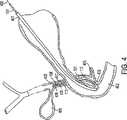
図1は、カテーテル装置100を示していて、この装置は胆管枝に造影剤を注入できると共に、括約筋切開術を実行するための、また、胆石を十二指腸へ移動させるための切断ワイヤを精密に位置決めできるものである。装置100に含まれているカテーテル101は、その定義として、近位端103から延在してなる近位側部分102と、遠位端104から短距離にわたり延在している遠位側部分105を備えてなる遠位側部分105とを含んでいる。代表的な用途においては、カテーテルは200cmの作業長さを有し、遠位側部分105は6cm〜9cmの長さを有している。通常は、遠位側部分105は、近位側部分102に比べて小さい直径を有していて、遠位側部分105の可撓性を向上されている。また、直径を小さくすることによって、遠位端104の外傷性は低くなって、遠位側部分105はより細い通路に到達できる一方、大径である近位側部分102は、特に近位側部分102が十二指腸内視鏡の作業通路と同一の広がりをもっているときに、必要なフープ強度と剛性とを提供する。例えば、近位側部分と遠位側部分との直径は、7Frと5Frと(すなわち、それぞれ0.09”と0.07”)の直径を有する。
【0017】
図2に示すように、カテーテル101は3つの管腔を有している。第1の管腔201の直径は、第2の管腔202と第3の管腔203との直径のいずれに比べても大きくなっている。ひとつの具体的な実施形態においては、第1の管腔201の直径は、近位側部分102においては0.040”であって、遠位側部分105における約0.037”へと細くなっていて、標準的な0。035”のガイドワイヤを受入れることができる。さらに、第1の管腔201はカテーテル101の中心からオフセットしている。
【0018】
第2の管腔202と第3の管腔203との双方の横断面はそれぞれ、第1の管腔201の横断面に比べて小さくなっていて、カテーテル101の中心線に対して相互にかつ第1の管腔201から半径方向にオフセットしている。ひとつの具体的な実施形態においては、第3の管腔203の横断面の直径は、近位側部分102においては0.028”であって、遠位側部分105における0.020”へと細くなっており、第2の管腔202の内径は近位側部分102における0.028”から遠位側部分105における0.020”へと細くなっている。後述するように、この第3の管腔203は、括約筋切開術を実行するための切断ワイヤを支持すると共に、適度な流速にて造影剤を注入する。切断ワイヤは、必要に応じて、後述するように配置される。第2の管腔202と第3の管腔203との間の角度的な隔たりは、約45゜であって、第1の管腔201と管腔202及び管腔203とのそれぞれの間の角度的な隔たりは、約157.5゜である。この構成及び上述の寸法によれば、近位側部分102は十二指腸内視鏡の作業通路を容易に通過することができる。
【0019】
再び図1及び図2を参照すると、管腔201、202、及び、203のそれぞれは、近位側部分102には入口ポートを、遠位側部分105には出口ポートを含んでいる。一般的には、詳しくは後述するが、第1の管腔201の出口ポートは遠位端104を通っていて、管腔202と203との出口ポートは、具体的な用途に応じて、遠位側部分105における異なった場所に位置している。
【0020】
図1において、近位側部分102の近位端103に隣接している入口ポートは、第1の管腔201へのアクセスを提供する入口ポート106と、任意的事項としてのルアーロック取付部107とを含んでいる。近位側に配置されてなる入口ポート108は、第2の管腔202へのアクセスを提供し、任意的事項としてのルアーロック取付部109を含んでいる。第3の管腔203のための近位側にある入口ポート110は、近位端103に取付けられてなるハンドル111の部分に対して同延に配置されている。この特定の構成は単なる例示であって、本発明を限定するものではないことを当業者は理解するだろう。当業者にあっては、本願記載の本発明の実施に際して、様々な別の構成を採用できることが明らかである。
【0021】
遠位側部分105を参照すると、この具体的な実施形態におけるカテーテル101は、カテーテル101の外方へ偏位してなる切断ワイヤ113の近位側に、膨張可能なバルーン112を支持している。本願出願人の権利に属するRowlandらの米国特許出願第09/154,834号に開示されているように、また、その全文を本願に参照して引用したように、第2の管腔202は、カテーテル101の側部を通って、膨張可能なバルーン112の内部にて、遠位側の出口ポートに出てくる。遠位側のポートを越える第2の管腔202の延長部分は、製造者にとって公知である方法によって密封シールされる。その結果、ルアーロック取付部109に取付けられた注射器(図示せず)などによって入口ポート104へ押流された流体は、バルーン112を20mmまでの範囲の直径を有するような、閉塞のための膨張直径に膨張させる。
【0022】
第1の管腔201は、カテーテル101を延通して、遠位端104の出口ポートにて終端する。従って、第1の管腔201は、入口ポート106を通ったガイドワイヤを受入れるように適合していて、ガイドワイヤはカテーテル101を通って延通して、遠位端104から出ると共に、カテーテルはかかるガイドワイヤに沿って摺動することができる。
【0023】
図3を参照すると、切断ワイヤ113の遠位端301は、第3の管腔203の遠位端に形成されてなるクランプ302に取付けられている。間隔を隔てて削除されてなるポート303と304によって、切断ワイヤ113の作業部分305は、カテーテル101から削除開口303を通って、カテーテル101に対して平行にカテーテルの外部へ出ることができると共に、ポート304と補強スリーブを通って、第3の管腔203の中へ戻ることができる。切断ワイヤ113は、第3の管腔203を延通して、図1に示したハンドル111に至り、この箇所で、近位端部分114に出現する。
【0024】
図1に示す如く、ハンドル111は、親指リング116にて終端してなる中央部材115を含んでいる。中央部材115は、対向した指リング118を有してなる本体部分117を延通していて、同本体部分に対して摺動するようになっている。中央部材115はカテーテル101に取付けられていて、カテーテル101の延長部分となっている。部材117は追加的に、切断ワイヤ113の近位端114をクランプするための内部コネクタ119を含んでいる。従って、本体117が図1に示すような遠位側位置にあるときには、カテーテル101の遠位側部分は本質的には図1に示すような直線状になっていて、切断ワイヤ113の作業部分305はカテーテル101に近接している。本体部分117を引っ込めることによって、切断ワイヤ113は、図3に示す如く、遠位端104を屈曲させて、カテーテルの主軸に対して本質的に直角な状態になるが、これについては後述する。
【0025】
コネクタブロック119と切断ワイヤ113とは、略導電性の部材であって、RFコネクタ120を介して、RF加熱源121に取付けられている。そうしたRF加熱源121を使用して、切断ワイヤ113に通電することによって、括約筋を切断することは、当業者に良く知られているが、これには、本発明の装置に適用できる括約筋切開術の手順のひとつの可能性を示そうとする以上の意図はない。
【0026】
次に、本願で説明している装置の構造に関して、具体的な用途について説明する。図4は、オディ括約筋403に隣接させて十二指腸402の中に十二指腸内視鏡401を配置した様子を一部破断して示した模式図である。図1に示したように構成されたカテーテル101を、オディ括約筋403に通過させて、膵管405を迂回させて、総胆管404へ挿入する。遠位端104は胆嚢406にまでは延びていない。
【0027】
図3のクランプ302と補強スリーブ306とを含んでなる遠位側部分105にある、一連の放射線不透過の目印406を利用して、X線透視検査によって、適切に位置決めする。カテーテル101は、図2及び図3に示すような、第1の管腔201の中に存在しているガイドワイヤ408を使用して又は使用せずに、位置決めをすることができる。造影剤を注入する目的のために、すべてのガイドワイヤ408を撤収して、造影剤を第1の管腔201に通して注入し、X線透視検査によって1又は複数の胆石409が存在しているか否かを確認する検査を行なう。処置手順中には、バルーン112を膨張させて総胆管404を閉塞し、造影剤が十二指腸402や膵管405に流入しないように閉鎖することも可能である。
【0028】
図5は、十二指腸402と、オディ括約筋403と、膵管405の一部分と、総胆管404とを示した拡大図である。図5において、カテーテル101は、十二指腸内視鏡401に対して位置決めされていて、オディ括約筋403の開口に通っている。ここでは、図1に示したハンドル111が近位側に引かれていて、遠位側部分105を本質的に直角の形態に偏向させて、切断ワイヤ113をオディ括約筋403の部分に当接している。次に、切断ワイヤ113にRF加熱を与えることによって、オディ括約筋403を切断して、その開口を拡大させる。十二指腸内視鏡を介したオディ括約筋の直視下において、括約筋切開術が実行されることは明らかであろう。
【0029】
さらに、他のカテーテルでも見られるように、ガイドワイヤと切断ワイヤとの管腔を有しているカテーテルは、遠位側部分105が十二指腸内視鏡から外に出たときに、特定の角度配向を呈する傾向がある。このような配向は、カテーテルが十二指腸内視鏡に挿入されたときの角度位置とは本質的に無関係である。管腔203は図2に示したようにオフセットしているので、遠位側部分105がオディ括約筋403を通過するときの、切断ワイヤ113の位置を改善する。具体的には、角度的なオフセットのために、切断ワイヤ113は総胆管404に対して良好に整列されて、切断ワイヤは膵管405の位置から離れる。
【0030】
図6は、括約筋切開術の後のカテーテルと、ガイドワイヤ408を使用した場合において、カテーテル101をガイドワイヤに沿って進めた後の様子を示している。また図6は、胆管404の胆石409を越えてバルーン112を動かした後のカテーテル101を示している。バルーン112を膨張させることで、カテーテル101を引戻す際には、バルーン112が胆石409を移動させて、オディ括約筋403に通して胆石を十二指腸402に追い出している。
【0031】
以上、図1に示した具体的なカテーテル装置の説明と、図4、図5、及び、図6を参照して説明したその使用方法とから明らかなように、単一のカテーテル装置によって、診断用の造影剤の注入を提供し、括約筋切開術を実行し、総胆管やその他の胆管枝の中の胆石を排除することができて、そのためにカテーテルを交換する必要は無い。さらに、管腔の配置とサイズとのために、カテーテル装置を用いて3つの機能を実行することが可能であって、かかる装置は標準的な十二指腸内視鏡の作業通路において使用すべく容易に適合することができる。その結果、十二指腸内視鏡は消化管を通して導入することができるので、胆管を切開したり、それに伴なう外科手術手順を必要とせずに、胆管枝から胆石を取除くことができる。そのため、すべての処置手順は、従来技術による処置手順に比べて、より迅速にかつ少ない構成要素を使用して、実行できるように適合している。最終的な効果は、患者の外傷を低減できると共に、処置手順を行なうための総合的な時間とコストとを低減できることである。
【0032】
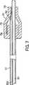
図1において、バルーン112は切断ワイヤ113の近位側に配置されている。図7は、他の実施形態を示していて、バルーン701は切断ワイヤ113の遠位側に配置されている。より詳しくは、管腔202Aの遠位端は、これは図3の第2の管腔202に対応しているのだが、密封シールされている。側面に向いた出口ポート702は、カテーテル101を削り取られてあるいは別の手段によって形成されていて、バルーン701が形成しているチャンバ703に開通している。第1のシール部分704と、バルーン701のシール部分705とは、開口702の近位側と遠位側とのそれぞれと、シールチャンバ703とを結合している。
【0033】
管腔202Aを通してバルーンの膨張流体を導入することによって、バルーン701は膨張して、バルーン701の状態に対応した閉塞状態になる。遠位側のバルーン701を膨張させつつ、カテーテル101を引き戻すことによって、胆管から胆石を回収することができる。この具体的な実施形態は、特に、胆石が胆管枝の上部に位置していて、遠位側部分105を胆石を越えた胆管枝に通して侵入させることを最小にしたいと判断されたときや、閉塞バルーンを越えて延びる遠位側部分105の長さを最小にしたいと内科医が望むような場合に適している。
【0034】
図8は、別の実施形態を示していて、オディ括約筋を拡大したり、診断において胆管枝に造影剤を注入したり、胆管枝の狭窄を治療するなどの、他の処置手順を実行するためのものである。この具体的な実施形態では、第2の管腔202Bの出口ポート801は、遠位側部分105の遠位端104に位置している。第1の管腔201はガイドワイヤのために使用して、ガイドワイヤを所定位置に残したままで、管腔202Bを使用して、造影剤を直接、胆管枝に注入する。処置手順が保証されるとしたなら、この装置を位置決めして、カテーテルを交換する必要なしに括約筋切開術を実行するであろう。
【0035】
さらに別の変形例として、内科医は、胆石の除去が必要であるか否かを判断するための造影剤の注入の目的のために、在来式のカテーテルを利用しても良い。治療が必要であると認められたならば、内科医は、図1に示した装置を使用して、前述の如く、管腔201に通すガイドワイヤを1回だけ交換すれば良い。
【0036】
上述の説明から明らかなように、妨害物による疾患の治療のひとつの段階は、通常は、切断ワイヤを内視鏡的に患部に進めて行なわれる、組織の切開である。前述の如く、カテーテルの先端部が所定位置に配置されたならば、カテーテルの先端部を屈曲させて(図5参照)、切断ワイヤ113を組織に対して露出させる。次に、RF加熱源121(図1参照)から切断ワイヤ113へ透熱性の電流を流すことによって、医師は、患部の組織を切断し焼灼することができる。切断ワイヤ113の位置決めと、切断ワイヤの露出部分の制御とを精密に行なうことによってのみ、安全かつ効果的な結果が得られる。同様に、針状ナイフがカテーテルの端部から遠位方向に延在しているときには、針状ナイフの露出した部分を正確に認知すると共に、切断手順にわたって維持する必要がある。
【0037】
図9は、ユーザが切断部材を所望の長さに調節した後に、切断部材が動くことを防止するような、本発明の実施形態についての拡大図である。切断部材900には、一連の止め具、歯止め、ないし、隆起領域901が配置されている。これらの隆起した領域901の間は、低い領域ないし窪み906になっている。窪み906は、管腔905の内周に沿って配置されてなる、対応する隆起領域902と相互作用する。対応する隆起領域902との相互作用によって、切断部材を使用するとき、切断部材が符号903の方向へ動くことを防止する。止め具には、ビードや突起その他の類似の表面の特徴が含まれ、それらの形状は丸くても尖っていても斜めでも良いことを当業者は理解するだろう。本発明によって抗される動きとは、切断部材やワイヤの管腔の内部におけるいずれかの軸線方向の変位である。止め具、歯止め、ないし、隆起領域901と、これらに対応する隆起領域902との配置は逆にしても良く、そうしたものも本発明の範囲に含まれることを当業者は理解するだろう。隆起領域の間の間隔は、露出している切断部材900の長さの指標としても用いることができる。
【0038】
図10は、ユーザが針状ナイフを正しい長さに配置することができるような、刃の目印1000を示した斜視図である。刃の目印は、色彩の目印や、様々な被膜(陽極処理や酸の浸漬)、インク、エッチング、その他の類似する技術であって、ユーザが針状ナイフの露出長さを視覚的に判断できるものであれば良い。目印は、例えば1mmなどの一定した長さにて表示される。例えば図10では、部分1001と1002と1003と1004とはそれぞれ、1mmの長さになっている。
【0039】
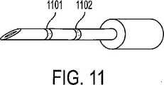
図11は、本発明の他の実施形態であって、針状ナイフにエッチング、刻印、又は、書込まれた線1101及び1102が露出した刃の様々な長さの指標になっている。ユーザが露出した刃の長さを判断できるものであれば、あらゆるタイプの目印が本発明の範囲に含まれることを当業者は理解するだろう。
【0040】
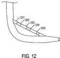
図12は、切断ワイヤ1201に目印を付けるやり方を示した斜視図である。切断ワイヤ1201の部分は、交互に、目印1202、1203、1204、及び、1205によって識別されていて、露出したワイヤの固定長さの指標になっている。
【0041】
内視鏡による処置手順が直視下において実行されるのであれば、図10、図11、及び、図12に示した目印によって、ユーザは切断ワイヤ又はナイフの露出長さを直接的に視認することができる。いったん針状ナイフや切断ワイヤを所望の長さに調節したならば、露出した刃を固定する。露出した刃の長さを固定するためには、切断ワイヤを2つの異なった場所にて保持する必要がある。まず、近位端にあるロック機構を備えた摺動ハンドルをロックする。この最初のロック機構については、図1において、任意的事項であるルアーロック取付部107と、任意的事項であるルアーロック取付部109と共に示されている。いったんルアーロック取付部(ないし同様な装置)を用いて摺動ハンドルをロックしたならば、切断ワイヤの遠位端を保持して、露出したナイフが管腔の内部に押戻されることの無いことを確保する。
【0042】
X線を使用して実行される内視鏡的な処置手順においては、放射線不透過の指標や、目印、色彩、数字、文字などを、切断器具に含めるようにして、露出した切断面の長さの指標とする。この事例では、露出した切断面の開始箇所の指標となる参照点を含めるようにして、参照点と放射線不透過の指標とを比較することによって、ユーザは切断面の露出を判断することができる。
【図面の簡単な説明】
【図1】 図1は、本発明に従って構成された装置の実施形態を示した平面図である。
【図2】 図2は、図1の線2−2に沿っての横断面図である。
【図3】 図3は、図2の線3−3に沿っての横断面図である。
【図4】 図4は、図1の装置を十二指腸内視鏡に通して配置して、造影剤を胆管枝に注入する様子を示した図である。
【図5】 図5は、図1の装置を括約筋切開術を実行すべく配置した様子を示した拡大図である。
【図6】 図6は、図1の装置を十二指腸内視鏡に通して、総胆管の内部の物質を追出すように配置した様子を示した図である。
【図7】 図7は、別の実施形態の装置について、図2の線7−7に沿って示した横断面図である。
【図8】 図8は、本発明のさらに別の実施形態について、図2の線7−7に沿って示した横断面図である。
【図9】 図9は、ユーザが切断部材を所望の長さに調節した後に、切断部材の動きを防止するためのの、本発明の実施形態を示した拡大図である。
【図10】 図10は、ユーザが針状ナイフを正しい長さに位置決めできるように、刃に目印を付ける方法を示した斜視図である。
【図11】 図11は、本発明の他の実施形態による、刃に目印を付ける方法を示した斜視図である。
【図12】 図12は、切断ワイヤないし切断部材に目印を付ける方法を示した斜視図である。[0001]
[Related Applications]
The present invention is described in US Pat. No. 5,547,469, US Pat. No. 5,868,698, US Pat. No. 5,683,362, and US patent application 09 / 154,834 to Rowland et al. All of these rights belong to the applicant and relate to improvements to the disclosed apparatus and method.
[0002]
BACKGROUND OF THE INVENTION
The present invention relates generally to such devices that are useful for diagnosing and treating biliary branches, and in particular to diagnosing and removing gallstones in the bile ducts and other parts of the biliary branches. It relates to a device used to make an incision inside an endoscopic catheter for ease.
[0003]
[Prior art]
So far, gallstones that have moved into the patient's common bile duct have been treated by common surgical procedures. The surgeon incised the bile duct to remove the gallstones and typically removed the gallbladder. In recent years, less invasive treatment modalities have replaced patient surgical procedures, long-term hospitalization, and recovery time, replacing such common surgical procedures.
For example, US Pat. No. 4,696,668 and US Pat. No. 4,781,677, both by Wilcox, describe a treatment modality that administers a dissolving drug to the bile duct to dissolve essentially all gallstones. Disclosure. More specifically, a catheter having a plurality of lumens for inflating and deflating each of the two balloons is passed through the bile duct to inject and aspirate the dissolved drug. When the balloon is inflated, the bile duct is occluded at two separate sites, and the dissolved drug is received in the sealed space thus created. Since such space is sealed from the remaining biliary branches, the dissolved drug accesses the gallbladder and all gallstones in the gallbladder pass through the gallbladder duct with the outflow of bile and pass from the base of the gallbladder. In addition, high concentrations of dissolved chemicals are trapped around the gallstones in the bile duct. After the gallstone has dissolved, the balloon is deflated and the catheter is collected. In this particular approach, the catheter is passed through the bile duct branch using standard duodenal endoscopy such as through the digestive tract. While this approach and similar approaches have the potential to minimize patient trauma, such treatment requires the duodenoscope to be placed on the patient over time and is inefficient. May cause adverse reactions to dissolved chemicals.
[0004]
In another approach, the surgeon introduces a surgical extractor into the biliary branch through at least a bile duct incision. For example, in Glassman US Pat. No. 3,108,593, a surgeon incises both the bile duct and the duodenum. The surgeon then passes the extractor through the bile duct incision, the bile duct branch, the odysphine sphincter, and the duodenum and out of the duodenal incision. The extractor includes a series of longitudinally spaced cages to capture any gallstones and remove the gallstones from any incision.
[0005]
U.S. Pat. No. 4,627,837 to Gonzalo discloses a catheter device that includes a pair of inflatable balloons at the distal end of the catheter. The catheter is guided to the duodenum through a bile duct incision. After the distal balloon has passed the Odi sphincter, both balloons are inflated to secure the catheter in place. This causes the catheter to be irrigated and flushed through the other lumen to capture all gallstones in the second balloon and remove them through the incised bile duct.
[0006]
According to yet another mode of treatment for stenosis, the surgeon inserts a catheter device through the bile duct or duodenum to dilate or dilate the Odi sphincter. For example, Kim U.S. Pat. No. 4,705,041 discloses a dilator as introduced through an incision between the bile duct and the Odi sphincter. An expandable tip expands the Odi sphincter. U.S. Pat. No. 5,035,696 to Rydell discloses an electrosurgical instrument that is passed from the duodenum to the Odi sphincter to perform a sphinctertomy. The device includes a cutting wire that is heated to cut the sphincter. Karpier US Pat. No. 5,024,617 discloses a similar device that can be passed through a duodenoscope. Sewell, Jr. U.S. Pat. No. 5,152,772 discloses a device for performing a sphincterotomy, including a knife that is passed through a bile duct incision to cut the sphincter.
[0007]
Using a device with a duodenoscope and sphincterotomy, as shown in the Rydell and Karpiel patents, physicians can diagnose biliary branch problems with minimal patient invasiveness. Can be treated. For example, the manner disclosed in these patents eliminates the need for surgery to incise the bile duct. As a result, these modalities can be implemented as outpatients or daily surgical procedures. These treatment procedures greatly reduce patient trauma and shorten hospital stay and recovery time. For example, if the physician determines that gallstones are present in the bile duct branches, particularly the common bile duct, the physician can insert a duodenoscope into the duodenum and visually recognize the Odi sphincter. The first catheter can then be advanced through the working channel of the duodenoscope with or without a guidewire and introduced into the bile duct branch through the Odi sphincter. The contrast medium injected through the catheter enables X-ray fluoroscopy and other imaging processes, and the presence of gallstones inside the bile duct branches can be confirmed. The physician then replaces the first catheter with a second catheter and performs a sphincterotomy of the type as disclosed in the Rydell and Karpiel patents. The second catheter is then replaced with a modified third catheter as shown in the Glassman patent or other equivalent, and the gallstone is withdrawn through the enlarged Odi sphincter. Thereafter, the correction catheter is operated to release gallstones into the duodenum. The catheter, all guidewires, and duodenoscope are withdrawn to complete the procedure.
[0008]
Since this procedure is only incised during the sphincterotomy compared to prior art procedures, there is significantly less trauma to the patient, however, as mentioned above, such a procedure has three separate catheters. And two catheter exchanges. These exchanges are necessary because the functions of the first, second, and third catheters are simply injecting contrast agent, performing sphincterostomy, and moving gallstones, respectively. This is because it is only. The time required to perform each catheter exchange increases patient trauma, lengthens the time required for the procedure, and reduces efficiency. Furthermore, each such procedure requires the use of a few separate catheter devices.
[0009]
Available multi-lumen catheters typically reduce the number of catheters and the replacement of the catheter used during the procedure, thus improving efficiency while reducing time and patient trauma. In addition, according to the multi-lumen device, since the previous catheter has been collected, the necessity of repositioning the next catheter is eliminated. Although a multi-lumen device needs to be repositioned, repositioning is significantly easier than when a single lumen catheter is used. Although precise positioning of the multi-lumen device is essential for safe and effective results, it is difficult to accurately position the multi-lumen device. The positioning of multi-lumen devices in the current state of the art is typically done by transmitting torque to the
[0010]
[Problems to be solved by the invention]
There is a need for an apparatus and method for precise placement of catheters, multi-lumen devices and needle knives. In addition, there is a need for an apparatus and method for precise depth control of needle knives and other cutting instruments.
[0011]
[Means for Solving the Problems]
Accordingly, the present invention provides an apparatus and method for precisely controlling the depth of incision performed through an endoscopic catheter. The present invention also provides an apparatus and method that can withstand the pressing force experienced by a cutting instrument that tends to push the cutting instrument back into the lumen.
[0012]
One embodiment of the present invention is an endoscopic catheter having a tissue cutting device disposed on the distal side in a lumen, and includes an exposed linear cutting member for cutting. An improvement for determining the amount of cutting member deployed, wherein the apparatus provides a plurality of radiopaque indicators spaced at radiologically measurable intervals on the cutting member. It is characterized by that. One embodiment of the present invention includes a radiopaque reference point and is characterized by determining the length of the deployed cutting member by referring to this index. The cutting member is a needle knife, the reference point is provided at the distal end of the catheter or sphincterotome, and the reference point is provided proximal to the cutting member of the sphincterotome in the catheter. The radiopaque indicator is displayed from the middle of the cutting member and includes a mark along the length of the cutting member, which is a function of the distance from the middle.
[0013]
In another embodiment of the present invention, the present invention is an endoscopic catheter having a needle knife that is cabled into a lumen, the needle knife being deployable from the distal end of the catheter. As an improvement to substantially prevent movement (in either axial direction) after the needle knife has been deployed, a spaced stop is provided along the cutting member. Which interacts with a notch at the distal end of the lumen and is characterized by resistance to movement. These stops are evenly spaced along the length of the cutting member.
[0014]
Another embodiment is an endoscopic catheter having a tissue cutting device disposed distally disposed in a lumen, with an exposed linear cutting member, deployed to cut Improvements are provided for determining the amount of the cutting member and substantially preventing movement of the cutting member. In this embodiment, the cutting member comprises a plurality of radiopaque indicators at radiologically measurable intervals, and a series of stops (or bumps) spaced along the cutting member. It is characterized in that at the distal end of the lumen, it interacts with a notch (or depression) to provide resistance to movement.
[0015]
The various objects, advantages and novel features of the present invention will become more fully apparent when the following detailed description is read with reference to the accompanying drawings.
[0016]
DETAILED DESCRIPTION OF THE INVENTION
FIG. 1 shows a
[0017]
As shown in FIG. 2, the
[0018]
The cross-sections of both the second lumen 202 and the
[0019]
Referring again to FIGS. 1 and 2, each of the
[0020]
In FIG. 1, the inlet port adjacent to the
[0021]
Referring to the
[0022]
The
[0023]
Referring to FIG. 3, the
[0024]
As shown in FIG. 1, the
[0025]
The
[0026]
Next, specific applications of the structure of the device described in the present application will be described. FIG. 4 is a schematic diagram showing a partially broken view of the
[0027]
Using a series of
[0028]
FIG. 5 is an enlarged view showing the
[0029]
In addition, as can be seen with other catheters, a catheter having a guide wire and a cutting wire lumen may have a specific angular orientation when the
[0030]
FIG. 6 shows a state after the
[0031]
As described above, as is clear from the description of the specific catheter device shown in FIG. 1 and the method of using the catheter device described with reference to FIGS. 4, 5, and 6, diagnosis can be performed by a single catheter device. Contrast media injections, sphincterotomy, and elimination of gallstones in the common bile duct and other biliary branches without the need to change catheters. Further, because of the placement and size of the lumen, it is possible to perform three functions using a catheter device, which is easy to use in the working path of a standard duodenoscope. Can fit. As a result, the duodenoscope can be introduced through the gastrointestinal tract, so that the gallstones can be removed from the bile duct branches without the need for incision of the bile duct or associated surgical procedures. As such, all treatment procedures are adapted to be performed more quickly and using fewer components than prior art treatment procedures. The net effect is that it can reduce patient trauma and reduce the overall time and cost of performing the procedure.
[0032]
In FIG. 1, the
[0033]
By introducing the inflation fluid of the balloon through the
[0034]
FIG. 8 shows another embodiment for performing other treatment procedures such as enlarging the Odi sphincter, injecting a contrast agent into the bile duct branch in diagnosis, or treating stenosis of the bile duct branch. belongs to. In this specific embodiment, the outlet port 801 of the second lumen 202B is located at the
[0035]
As yet another variation, the physician may utilize a conventional catheter for the purpose of injecting contrast media to determine whether gallstone removal is necessary. If the treatment is found to be necessary, the physician need only replace the guidewire that passes through the
[0036]
As is apparent from the above description, one stage of treatment of a disease caused by an obstruction is a tissue incision that is usually performed with a cutting wire advanced endoscopically into the affected area. As described above, when the distal end portion of the catheter is disposed at a predetermined position, the distal end portion of the catheter is bent (see FIG. 5), and the
[0037]
FIG. 9 is an enlarged view of an embodiment of the present invention that prevents the cutting member from moving after the user has adjusted the cutting member to a desired length. The cutting
[0038]
FIG. 10 is a perspective view showing the
[0039]
FIG. 11 is another embodiment of the present invention, which is an indication of the various lengths of the blades with exposed
[0040]
FIG. 12 is a perspective view showing how to mark the
[0041]
If the endoscopic procedure is performed under direct vision, the user can directly see the exposed length of the cutting wire or knife with the landmarks shown in FIG. 10, FIG. 11, and FIG. Can do. Once the needle knife or cutting wire has been adjusted to the desired length, the exposed blade is secured. In order to fix the length of the exposed blade, it is necessary to hold the cutting wire at two different locations. First, the sliding handle with the locking mechanism at the proximal end is locked. This initial locking mechanism is shown in FIG. 1 together with a luer
[0042]
In an endoscopic procedure performed using X-rays, the length of the exposed cut surface should be such that radiopaque indicators, landmarks, colors, numbers, letters, etc. are included in the cutting instrument. It is an index of safety. In this case, the user can determine the exposure of the cut surface by including a reference point that is an index of the start location of the exposed cut surface and comparing the reference point with the radiopaque index. .
[Brief description of the drawings]
FIG. 1 is a plan view illustrating an embodiment of an apparatus constructed in accordance with the present invention.
FIG. 2 is a cross-sectional view taken along line 2-2 of FIG.
FIG. 3 is a cross-sectional view taken along line 3-3 of FIG.
4 is a view showing a state in which the apparatus of FIG. 1 is placed through a duodenoscope and a contrast medium is injected into a bile duct branch. FIG.
FIG. 5 is an enlarged view showing the arrangement of the apparatus of FIG. 1 to perform a sphincterotomy.
6 is a view showing a state in which the device of FIG. 1 is placed through a duodenoscope so as to expel a substance inside the common bile duct.
FIG. 7 is a cross-sectional view of the apparatus of another embodiment, taken along line 7-7 in FIG.
FIG. 8 is a cross-sectional view taken along line 7-7 of FIG. 2 for yet another embodiment of the present invention.
FIG. 9 is an enlarged view illustrating an embodiment of the present invention for preventing movement of the cutting member after the user has adjusted the cutting member to a desired length.
FIG. 10 is a perspective view showing a method of marking the blade so that the user can position the needle knife at the correct length.
FIG. 11 is a perspective view illustrating a method of marking a blade according to another embodiment of the present invention.
FIG. 12 is a perspective view showing a method of marking a cutting wire or a cutting member.
Claims (22)
Translated fromJapanese露出した直線状の切断部材を備え、切断すべく配備された切断部材の量を決定するための改良であって、この内視鏡カテーテルが、
前記切断部材に、複数の放射線不透過の指標を、放射線学的に測定可能な間隔を隔てて配置して提供する、ことを特徴とする内視鏡カテーテル。An endoscopic catheter having a tissue cutting device disposed distally in a lumen,
An improvement for determining the amount of cutting member deployed to be cut with an exposed linear cutting member, the endoscopic catheter comprising:
An endoscopic catheter, wherein the cutting member is provided with a plurality of radiopaque indicators arranged at radiologically measurable intervals.
放射線不透過の参照点を有し、前記指標を参照することによって、展開した前記切断部材の長さを決定する、ことを特徴とする請求項1に記載の内視鏡カテーテル。The endoscopic catheter is
The endoscope catheter according to claim 1, wherein the endoscope catheter has a radiopaque reference point, and the length of the developed cutting member is determined by referring to the index.
露出した直線状の切断部材を備え、切断すべく配備された切断部材の量を決定するための改良であって、この内視鏡カテーテルが、
前記切断部材に、複数の放射線不透過の指標を、放射線学的に測定可能な間隔を隔てて配置して提供し、
放射線不透過の参照点を有し、前記指標を参照することによって、展開した前記切断部材の長さを決定する、ことを特徴とする内視鏡カテーテル。An endoscopic catheter having a tissue cutting device disposed distally in a lumen,
An improvement for determining the amount of cutting member deployed to be cut with an exposed linear cutting member, the endoscopic catheter comprising:
Providing said cutting member with a plurality of radiopaque indicators spaced at radiologically measurable intervals;
An endoscope catheter having a radiopaque reference point and determining a length of the developed cutting member by referring to the index.
露出した直線状の切断部材を備え、切断すべく配備された切断部材の量を決定すると共に、前記切断部材の動きを防止するための改良であって、この内視鏡カテーテルが、
複数の放射線不透過の指標を、放射線学的に測定可能な間隔にて備えるように、前記切断部材を提供し、1又は複数の間隔を隔てた止め具を、前記管腔の遠位端にて、前記管腔の遠位端の1又は複数の切り欠きに相互作用させて、前記動きに対して抵抗を与える、ことを特徴とする内視鏡カテーテル。An endoscopic catheter having a tissue cutting device disposed distally in a lumen,
An endoscopic catheter comprising an exposed linear cutting member for determining the amount of cutting member deployed to cut and preventing movement of the cutting member, the endoscopic catheter comprising:
The cutting member is provided to provide a plurality of radiopaque indicators at radiologically measurable intervals, and one or more spaced stops are provided at the distal end of the lumen. An endoscopic catheter that interacts with one or more notches at the distal end of the lumen to provide resistance to the movement.
放射線不透過の参照点を有し、前記指標を参照することによって、展開した前記切断部材の長さを決定する、ことを特徴とする請求項10に記載の内視鏡カテーテル。The endoscopic catheter is
The endoscopic catheter according to claim 10, wherein the endoscope catheter has a radiopaque reference point, and the length of the deployed cutting member is determined by referring to the index.
露出した直線状の切断部材を備え、切断すべく配備された切断部材の量を決定すると共に、前記切断部材の動きを防止するための改良であって、この内視鏡カテーテルが、
複数の放射線不透過の指標を、放射線学的に測定可能な間隔にて備えるようにして、前記切断部材を提供し、1又は複数の間隔を隔てた止め具を、前記管腔の遠位端にて、前記管腔の遠位端の1又は複数の切り欠きに相互作用させて、前記動きに対して抵抗を与え、
放射線不透過の参照点を有し、前記指標を参照することによって、展開した前記切断部材の長さを決定する、ことを特徴とする内視鏡カテーテル。An endoscopic catheter having a tissue cutting device disposed distally in a lumen,
An endoscopic catheter comprising an exposed linear cutting member for determining the amount of cutting member deployed to cut and preventing movement of the cutting member, the endoscopic catheter comprising:
The cutting member is provided with a plurality of radiopaque indicators at radiologically measurable intervals, and one or more spaced stops are provided at the distal end of the lumen. Interacting with one or more notches at the distal end of the lumen to provide resistance to the movement;
An endoscope catheter having a radiopaque reference point and determining a length of the developed cutting member by referring to the index.
Applications Claiming Priority (2)
| Application Number | Priority Date | Filing Date | Title |
|---|---|---|---|
| US09/963,676US20030060842A1 (en) | 2001-09-27 | 2001-09-27 | Method and apparatus for measuring and controlling blade depth of a tissue cutting apparatus in an endoscopic catheter |
| PCT/US2002/030777WO2003026524A2 (en) | 2001-09-27 | 2002-09-27 | Method and apparatus for measuring and controlling the exposed length of a tissue cutting device in an endoscopic catheter |
Publications (2)
| Publication Number | Publication Date |
|---|---|
| JP2005503863A JP2005503863A (en) | 2005-02-10 |
| JP4520741B2true JP4520741B2 (en) | 2010-08-11 |
Family
ID=25507554
Family Applications (1)
| Application Number | Title | Priority Date | Filing Date |
|---|---|---|---|
| JP2003530165AExpired - Fee RelatedJP4520741B2 (en) | 2001-09-27 | 2002-09-27 | Endoscopic catheter |
Country Status (6)
| Country | Link |
|---|---|
| US (2) | US20030060842A1 (en) |
| EP (1) | EP1434533B1 (en) |
| JP (1) | JP4520741B2 (en) |
| CA (1) | CA2430209A1 (en) |
| DE (1) | DE60236097D1 (en) |
| WO (1) | WO2003026524A2 (en) |
Families Citing this family (45)
| Publication number | Priority date | Publication date | Assignee | Title |
|---|---|---|---|---|
| IL149689A (en)* | 2002-05-15 | 2009-07-20 | Roei Medical Technologies Ltd | Working tool for accurate lateral resection of biological tissue and a method for use thereof |
| RU2258480C1 (en)* | 2004-11-03 | 2005-08-20 | Российский центр функциональной хирургической гастроэнтерологии (РЦФХГ) | Method for nontypical endoscopic papillotomy |
| JP4940391B2 (en)* | 2004-11-24 | 2012-05-30 | クック メディカル テクノロジーズ エルエルシー | Improvement of sphincterotome |
| JP4774272B2 (en)* | 2005-10-19 | 2011-09-14 | Hoya株式会社 | Endoscopic high-frequency incision tool |
| US20070255278A1 (en)* | 2006-04-28 | 2007-11-01 | Nobis Rudolph H | Apparatus and method for deploying a cutting element during an endoscopic mucosal resection |
| US7867228B2 (en)* | 2006-04-28 | 2011-01-11 | Ethicon Endo-Surgery, Inc. | Apparatus and method for performing an endoscopic mucosal resection |
| US20070270643A1 (en)* | 2006-05-19 | 2007-11-22 | Ifung Lu | Lumen stabilizer for endoscopic mucosal resection |
| US8075556B2 (en)* | 2006-05-23 | 2011-12-13 | Andres Betts | High frequency epidural neuromodulation catheter for effectuating RF treatment in spinal canal and method of using same |
| WO2008048814A2 (en)* | 2006-10-17 | 2008-04-24 | Wilson-Cook Medical Inc. | Wire-guided aspiration needle |
| US7922696B2 (en) | 2007-01-24 | 2011-04-12 | Access Scientific, Inc. | Access device |
| EP3093038B1 (en) | 2007-04-18 | 2019-05-22 | Access Scientific, Inc. | Access device |
| EP2150187A2 (en)* | 2007-04-18 | 2010-02-10 | Access Scientific, Inc. | Access device |
| JP5048391B2 (en)* | 2007-04-27 | 2012-10-17 | 直久 矢作 | Endoscopic treatment tool |
| WO2009012385A1 (en) | 2007-07-19 | 2009-01-22 | Medical Components, Inc. | Venous access port assembly with x-ray discernable indicia |
| US8702641B2 (en) | 2009-04-03 | 2014-04-22 | Metamodix, Inc. | Gastrointestinal prostheses having partial bypass configurations |
| ES2503553T3 (en) | 2009-04-03 | 2014-10-07 | Metamodix, Inc. | Modular Gastrointestinal Prosthesis |
| US9278019B2 (en) | 2009-04-03 | 2016-03-08 | Metamodix, Inc | Anchors and methods for intestinal bypass sleeves |
| US9173760B2 (en) | 2009-04-03 | 2015-11-03 | Metamodix, Inc. | Delivery devices and methods for gastrointestinal implants |
| AU2010271294B2 (en) | 2009-07-10 | 2015-09-03 | Metamodix, Inc. | External anchoring configurations for modular gastrointestinal prostheses |
| AU2011213558A1 (en) | 2010-02-08 | 2012-09-27 | Access Scientific, Inc. | Access device |
| CN101803948A (en)* | 2010-03-29 | 2010-08-18 | 韩俊峰 | Reverse temperature control combined probe type tumor thermal-therapeutic apparatus |
| US8992540B2 (en)* | 2010-07-22 | 2015-03-31 | Kyphon Sarl | Adjustable surgical instruments and methods of use and fabrication |
| US9463059B2 (en) | 2012-02-09 | 2016-10-11 | Boston Scientific Scimed, Inc. | Cutting tool with circulating wire |
| CN102949225A (en)* | 2012-11-21 | 2013-03-06 | 武汉大学 | Visualization endoscopic incision knife device |
| WO2014113483A1 (en) | 2013-01-15 | 2014-07-24 | Metamodix, Inc. | System and method for affecting intestinal microbial flora |
| US9566087B2 (en) | 2013-03-15 | 2017-02-14 | Access Scientific, Llc | Vascular access device |
| EP4427687A3 (en) | 2014-09-19 | 2024-11-20 | Boston Scientific Scimed Inc. | Method of attaching a mesh to a coated loop member of a surgical snare device |
| KR101672992B1 (en)* | 2014-12-05 | 2016-11-04 | 가톨릭대학교 산학협력단 | Snare |
| US11027099B2 (en) | 2015-04-30 | 2021-06-08 | Smiths Medical Asd, Inc. | Vascular access device |
| JP7004492B2 (en)* | 2015-07-09 | 2022-01-21 | 三菱マテリアル株式会社 | Packing box, packing method and removal method |
| CN116373331A (en)* | 2015-10-23 | 2023-07-04 | 安多卓思公司 | Method of attaching a mesh to a coated loop member of a surgical snare device |
| US9622897B1 (en) | 2016-03-03 | 2017-04-18 | Metamodix, Inc. | Pyloric anchors and methods for intestinal bypass sleeves |
| WO2017201424A1 (en) | 2016-05-19 | 2017-11-23 | Metamodix, Inc. | Pyloric anchor retrieval tools and methods |
| US20210212756A1 (en)* | 2017-08-25 | 2021-07-15 | Nasser Rafiee | Tissue cutting systems and methods |
| US12133962B2 (en) | 2017-08-25 | 2024-11-05 | Transmural Systems Llc | Catheters and manipulators with articulable ends |
| CN111050834A (en)* | 2017-09-01 | 2020-04-21 | 国际私人银行有限责任公司 | Sphincterotome devices and methods and uses thereof |
| US10569059B2 (en) | 2018-03-01 | 2020-02-25 | Asspv, Llc | Guidewire retention device |
| US11737851B2 (en) | 2018-06-28 | 2023-08-29 | Cook Medical Technologies Llc | Medical devices for magnetic resonance imaging and related methods |
| US11337753B2 (en) | 2020-07-03 | 2022-05-24 | Telltale Llc | Tissue cutting systems and methods |
| EP4210608A4 (en)* | 2020-09-12 | 2024-10-16 | The United States of America, as represented by the Secretary, Department of Health and Human Services | TISSUE CUTTING SYSTEMS AND METHODS |
| WO2022187408A1 (en)* | 2021-03-03 | 2022-09-09 | Boston Scientific Scimed, Inc. | Measurement markings in distal tip imaging field of view |
| CN115645038B (en)* | 2022-10-31 | 2025-04-11 | 杭州莱恩瑟特医疗技术有限公司 | A kind of cutting knife handle and installation method thereof |
| US20240206863A1 (en)* | 2022-12-27 | 2024-06-27 | Transmural Systems Llc | Tissue cutting systems and methods |
| AU2023420320A1 (en) | 2022-12-27 | 2025-07-17 | Transmural Systems Llc | Catheter and actuator systems and methods |
| CN117338400B (en)* | 2023-12-05 | 2024-03-12 | 上海宇度医学科技股份有限公司 | Cutting mechanism convenient for piercing flaring for endoscope |
Family Cites Families (75)
| Publication number | Priority date | Publication date | Assignee | Title |
|---|---|---|---|---|
| US518600A (en)* | 1894-04-24 | Surgical instrument | ||
| US2715899A (en)* | 1952-11-21 | 1955-08-23 | Maclean Kenneth Sheldon | Curette |
| US3108593A (en)* | 1961-03-13 | 1963-10-29 | Jacob A Glassman | Surgical extractor |
| DE2443558B2 (en)* | 1974-09-11 | 1979-01-04 | Siemens Ag, 1000 Berlin Und 8000 Muenchen | Device for puncturing internal organs and vessels |
| US4273128A (en)* | 1980-01-14 | 1981-06-16 | Lary Banning G | Coronary cutting and dilating instrument |
| US4588399A (en)* | 1980-05-14 | 1986-05-13 | Shiley Incorporated | Cannula with radiopaque tip |
| US4476863A (en)* | 1981-03-09 | 1984-10-16 | Kanshin Nikolai N | Surgical instrument for establishing circular coloanastomoses |
| US5421819A (en)* | 1992-08-12 | 1995-06-06 | Vidamed, Inc. | Medical probe device |
| US4979951A (en)* | 1984-05-30 | 1990-12-25 | Simpson John B | Atherectomy device and method |
| US4627837A (en)* | 1984-05-30 | 1986-12-09 | German Gonzalo | Catheter device |
| US4705041A (en)* | 1984-07-06 | 1987-11-10 | Kim Il G | Dilator for Sphincter of Oddi |
| JPS6126466U (en)* | 1984-07-23 | 1986-02-17 | 日本電気株式会社 | katsuta knife |
| JPS61105525U (en)* | 1984-12-19 | 1986-07-04 | ||
| US4781677A (en)* | 1985-07-17 | 1988-11-01 | Wilcox Gilbert M | Method of treatment utilizing a double balloon nasobiliary occlusion catheter |
| US4696668A (en)* | 1985-07-17 | 1987-09-29 | Wilcox Gilbert M | Double balloon nasobiliary occlusion catheter for treating gallstones and method of using the same |
| US4811735A (en)* | 1987-07-30 | 1989-03-14 | Kensey Nash Corporation | Stone destroying catheter and method of use |
| JPH0432083Y2 (en)* | 1987-11-02 | 1992-07-31 | ||
| US5053044A (en)* | 1988-01-11 | 1991-10-01 | Devices For Vascular Intervention, Inc. | Catheter and method for making intravascular incisions |
| US5024617A (en)* | 1989-03-03 | 1991-06-18 | Wilson-Cook Medical, Inc. | Sphincterotomy method and device having controlled bending and orientation |
| US5018530A (en)* | 1989-06-15 | 1991-05-28 | Research Corporation Technologies, Inc. | Helical-tipped lesion localization needle device and method of using the same |
| US5226909A (en)* | 1989-09-12 | 1993-07-13 | Devices For Vascular Intervention, Inc. | Atherectomy device having helical blade and blade guide |
| US5035696A (en)* | 1990-02-02 | 1991-07-30 | Everest Medical Corporation | Electrosurgical instrument for conducting endoscopic retrograde sphincterotomy |
| US5095915A (en)* | 1990-03-19 | 1992-03-17 | Target Therapeutics | Guidewire with flexible distal tip |
| US5209749A (en)* | 1990-05-11 | 1993-05-11 | Applied Urology Inc. | Fluoroscopically alignable cutter assembly and method of using the same |
| US5395311A (en)* | 1990-05-14 | 1995-03-07 | Andrews; Winston A. | Atherectomy catheter |
| US5181920A (en)* | 1990-06-08 | 1993-01-26 | Devices For Vascular Intervention, Inc. | Atherectomy device with angioplasty balloon and method |
| US5078722A (en)* | 1990-08-14 | 1992-01-07 | Cordis Corporation | Method and apparatus for removing deposits from a vessel |
| US5152771A (en)* | 1990-12-31 | 1992-10-06 | The Board Of Supervisors Of Louisiana State University | Valve cutter for arterial by-pass surgery |
| US5152763A (en)* | 1991-04-02 | 1992-10-06 | Johnson Lanny L | Method for grafting bone |
| US5241970A (en)* | 1991-05-17 | 1993-09-07 | Wilson-Cook Medical, Inc. | Papillotome/sphincterotome procedures and a wire guide specially |
| US5256158A (en)* | 1991-05-17 | 1993-10-26 | Act Medical, Inc. | Device having a radiopaque marker for endoscopic accessories and method of making same |
| US5152772A (en)* | 1991-07-10 | 1992-10-06 | Sewell Jr Frank | Sphincterotomy catheter and method |
| NL9101534A (en)* | 1991-09-10 | 1993-04-01 | Cordis Europ | METHOD FOR MANUFACTURING A DOUBLE LUMEN CATHETER, CATHETER AND CATHETER ASSEMBLY MADE THEREOF |
| US6277084B1 (en)* | 1992-03-31 | 2001-08-21 | Boston Scientific Corporation | Ultrasonic medical device |
| EP0633798B1 (en)* | 1992-03-31 | 2003-05-07 | Boston Scientific Corporation | Vascular filter |
| US5536248A (en)* | 1992-05-11 | 1996-07-16 | Arrow Precision Products, Inc. | Method and apparatus for electrosurgically obtaining access to the biliary tree and placing a stent therein |
| US5599300A (en)* | 1992-05-11 | 1997-02-04 | Arrow Precision Products, Inc. | Method for electrosurgically obtaining access to the biliary tree with an adjustably positionable needle-knife |
| US5779724A (en)* | 1992-12-04 | 1998-07-14 | Werner; Richard S. | Retractable surgical knife |
| US5322055B1 (en)* | 1993-01-27 | 1997-10-14 | Ultracision Inc | Clamp coagulator/cutting system for ultrasonic surgical instruments |
| US5425376A (en)* | 1993-09-08 | 1995-06-20 | Sofamor Danek Properties, Inc. | Method and apparatus for obtaining a biopsy sample |
| US5427115A (en)* | 1993-09-13 | 1995-06-27 | Boston Scientific Corporation | Apparatus for stricture diagnosis and treatment |
| US5921924A (en)* | 1993-12-03 | 1999-07-13 | Avitall; Boaz | Mapping and ablation catheter system utilizing multiple control elements |
| US5487385A (en)* | 1993-12-03 | 1996-01-30 | Avitall; Boaz | Atrial mapping and ablation catheter system |
| US5730127A (en)* | 1993-12-03 | 1998-03-24 | Avitall; Boaz | Mapping and ablation catheter system |
| DE4410732C2 (en)* | 1994-03-28 | 1997-05-07 | Amatech Gmbh & Co Kg | Method for arranging a transponder unit having at least one chip and a wire coil on a substrate, as well as chip card with a correspondingly arranged transponder unit |
| US5452732A (en)* | 1994-04-26 | 1995-09-26 | Bircoll; Mel | Method of dissecting along connective tissue lines |
| ES2094010T3 (en)* | 1994-05-11 | 1997-01-01 | Schneider Europ Ag | ASSEMBLY FOR THE EXTENSION OF A GUIDE WIRE. |
| US5547469A (en)* | 1994-05-13 | 1996-08-20 | Boston Scientific Corporation | Apparatus for performing diagnostic and therapeutic modalities in the biliary tree |
| US5542948A (en)* | 1994-05-24 | 1996-08-06 | Arrow Precision Products, Inc. | Surgical combination inject and snare apparatus |
| US5458112A (en)* | 1994-08-15 | 1995-10-17 | Arrow Precision Products, Inc. | Biliary biopsy device |
| US5571136A (en)* | 1994-08-15 | 1996-11-05 | Medical Innovations Corporation | Forceps with guide wire |
| US5584843A (en)* | 1994-12-20 | 1996-12-17 | Boston Scientific Corporation | Shaped wire multi-burr rotational ablation device |
| US5609604A (en)* | 1995-10-16 | 1997-03-11 | Ethicon Endo-Surgery, Inc. | Trocar with improved blade attachment |
| JP3563857B2 (en)* | 1996-01-30 | 2004-09-08 | ペンタックス株式会社 | Endoscope |
| CA2245775C (en)* | 1996-02-12 | 2004-04-06 | David Finn | Method and device for bonding a wire conductor |
| US5830224A (en)* | 1996-03-15 | 1998-11-03 | Beth Israel Deaconess Medical Center | Catheter apparatus and methodology for generating a fistula on-demand between closely associated blood vessels at a pre-chosen anatomic site in-vivo |
| US5810807A (en)* | 1996-05-22 | 1998-09-22 | Ganz; Robert A. | Sphincterotome with deflectable cutting plane and method of using the same |
| US6007522A (en)* | 1996-09-13 | 1999-12-28 | Boston Scientific Corporation | Single operator exchange biliary catheter |
| US5810832A (en)* | 1996-12-27 | 1998-09-22 | Blasingame; James | Instrument for placement of cerclage wire |
| US6045565A (en)* | 1997-11-04 | 2000-04-04 | Scimed Life Systems, Inc. | Percutaneous myocardial revascularization growth factor mediums and method |
| US6142955A (en)* | 1997-09-19 | 2000-11-07 | United States Surgical Corporation | Biopsy apparatus and method |
| JPH11128240A (en)* | 1997-10-31 | 1999-05-18 | Olympus Optical Co Ltd | Treater for endoscope |
| US6056743A (en)* | 1997-11-04 | 2000-05-02 | Scimed Life Systems, Inc. | Percutaneous myocardial revascularization device and method |
| US6036682A (en)* | 1997-12-02 | 2000-03-14 | Scimed Life Systems, Inc. | Catheter having a plurality of integral radiopaque bands |
| US5951580A (en)* | 1998-03-23 | 1999-09-14 | Ashraf; Bahman | Scalpel having two blades adjustably separable |
| US5968061A (en)* | 1998-04-27 | 1999-10-19 | Theodor Esser | Endoscopic surgical instrument for the implementation of endoscopic surgical procedures |
| US6146387A (en)* | 1998-08-26 | 2000-11-14 | Linvatec Corporation | Cannulated tissue anchor system |
| EP1185200B1 (en)* | 1999-06-05 | 2008-01-09 | Wilson-Cook Medical Inc. | Indicia for an endoscopic medical device |
| JP3752402B2 (en)* | 1999-06-23 | 2006-03-08 | オリンパス株式会社 | Method for manufacturing endoscope treatment tool |
| US6620172B1 (en)* | 1999-07-01 | 2003-09-16 | Medsource Technologies, Inc. | Entraining biological calculi |
| AU2001243554A1 (en)* | 2000-03-10 | 2001-09-24 | Radius Medical Technologies, Inc. | Surgical snare apparatus |
| US6565588B1 (en)* | 2000-04-05 | 2003-05-20 | Pathway Medical Technologies, Inc. | Intralumenal material removal using an expandable cutting device |
| US6574497B1 (en)* | 2000-12-22 | 2003-06-03 | Advanced Cardiovascular Systems, Inc. | MRI medical device markers utilizing fluorine-19 |
| US6602267B2 (en)* | 2001-10-17 | 2003-08-05 | Medcanica, Inc. | Articulable and reciprocable surgical knife |
| US20050070821A1 (en)* | 2003-07-31 | 2005-03-31 | Deal Stephen E. | System and method for introducing a prosthesis |
- 2001
- 2001-09-27USUS09/963,676patent/US20030060842A1/ennot_activeAbandoned
- 2002
- 2002-09-27JPJP2003530165Apatent/JP4520741B2/ennot_activeExpired - Fee Related
- 2002-09-27EPEP02778379Apatent/EP1434533B1/ennot_activeExpired - Lifetime
- 2002-09-27DEDE60236097Tpatent/DE60236097D1/ennot_activeExpired - Lifetime
- 2002-09-27CACA002430209Apatent/CA2430209A1/ennot_activeAbandoned
- 2002-09-27WOPCT/US2002/030777patent/WO2003026524A2/enactiveApplication Filing
- 2008
- 2008-06-27USUS12/147,804patent/US20090005637A1/ennot_activeAbandoned
Also Published As
| Publication number | Publication date |
|---|---|
| CA2430209A1 (en) | 2003-04-03 |
| DE60236097D1 (en) | 2010-06-02 |
| US20030060842A1 (en) | 2003-03-27 |
| EP1434533A2 (en) | 2004-07-07 |
| JP2005503863A (en) | 2005-02-10 |
| WO2003026524A2 (en) | 2003-04-03 |
| US20090005637A1 (en) | 2009-01-01 |
| EP1434533B1 (en) | 2010-04-21 |
| WO2003026524A3 (en) | 2003-10-30 |
Similar Documents
| Publication | Publication Date | Title |
|---|---|---|
| JP4520741B2 (en) | Endoscopic catheter | |
| JP4537066B2 (en) | Device for positioning and maintaining an endoscopic instrument | |
| US6676659B2 (en) | Steerable sphincterotome and methods for cannulation, papillotomy and sphincterotomy | |
| JP4366077B2 (en) | Steerable sphincter instrument and method for cannulation, nipple incision and sphincter incision | |
| US6443924B1 (en) | Apparatus for performing diagnostic and therapeutic modalities in the biliary tree | |
| AU2001281264B2 (en) | Steerable sphincterotome and methods for cannulation, papillotomy and sphincterotomy | |
| AU2001281264A1 (en) | Steerable sphincterotome and methods for cannulation, papillotomy and sphincterotomy | |
| AU2002340044A1 (en) | Method and apparatus for measuring and controlling the exposed length of a tissue cutting device in an endoscopic catheter | |
| AU2002352906B2 (en) | Method of and apparatus for positioning and maintaining the position of endoscopic instruments | |
| AU2007203629A1 (en) | Method of and apparatus for positioning and maintaining the position of endoscopic instructions |
Legal Events
| Date | Code | Title | Description |
|---|---|---|---|
| A711 | Notification of change in applicant | Free format text:JAPANESE INTERMEDIATE CODE: A711 Effective date:20040728 | |
| A521 | Request for written amendment filed | Free format text:JAPANESE INTERMEDIATE CODE: A821 Effective date:20040728 | |
| A621 | Written request for application examination | Free format text:JAPANESE INTERMEDIATE CODE: A621 Effective date:20050920 | |
| A131 | Notification of reasons for refusal | Free format text:JAPANESE INTERMEDIATE CODE: A131 Effective date:20081110 | |
| A601 | Written request for extension of time | Free format text:JAPANESE INTERMEDIATE CODE: A601 Effective date:20090210 | |
| A602 | Written permission of extension of time | Free format text:JAPANESE INTERMEDIATE CODE: A602 Effective date:20090218 | |
| A521 | Request for written amendment filed | Free format text:JAPANESE INTERMEDIATE CODE: A523 Effective date:20090310 | |
| A131 | Notification of reasons for refusal | Free format text:JAPANESE INTERMEDIATE CODE: A131 Effective date:20090406 | |
| A601 | Written request for extension of time | Free format text:JAPANESE INTERMEDIATE CODE: A601 Effective date:20090706 | |
| A602 | Written permission of extension of time | Free format text:JAPANESE INTERMEDIATE CODE: A602 Effective date:20090713 | |
| A601 | Written request for extension of time | Free format text:JAPANESE INTERMEDIATE CODE: A601 Effective date:20090806 | |
| A602 | Written permission of extension of time | Free format text:JAPANESE INTERMEDIATE CODE: A602 Effective date:20090813 | |
| A601 | Written request for extension of time | Free format text:JAPANESE INTERMEDIATE CODE: A601 Effective date:20090907 | |
| A602 | Written permission of extension of time | Free format text:JAPANESE INTERMEDIATE CODE: A602 Effective date:20090914 | |
| A521 | Request for written amendment filed | Free format text:JAPANESE INTERMEDIATE CODE: A523 Effective date:20091006 | |
| A02 | Decision of refusal | Free format text:JAPANESE INTERMEDIATE CODE: A02 Effective date:20091203 | |
| A521 | Request for written amendment filed | Free format text:JAPANESE INTERMEDIATE CODE: A523 Effective date:20100324 | |
| A911 | Transfer to examiner for re-examination before appeal (zenchi) | Free format text:JAPANESE INTERMEDIATE CODE: A911 Effective date:20100409 | |
| TRDD | Decision of grant or rejection written | ||
| A01 | Written decision to grant a patent or to grant a registration (utility model) | Free format text:JAPANESE INTERMEDIATE CODE: A01 Effective date:20100428 | |
| A01 | Written decision to grant a patent or to grant a registration (utility model) | Free format text:JAPANESE INTERMEDIATE CODE: A01 | |
| A61 | First payment of annual fees (during grant procedure) | Free format text:JAPANESE INTERMEDIATE CODE: A61 Effective date:20100521 | |
| FPAY | Renewal fee payment (event date is renewal date of database) | Free format text:PAYMENT UNTIL: 20130528 Year of fee payment:3 | |
| R150 | Certificate of patent or registration of utility model | Free format text:JAPANESE INTERMEDIATE CODE: R150 | |
| FPAY | Renewal fee payment (event date is renewal date of database) | Free format text:PAYMENT UNTIL: 20130528 Year of fee payment:3 | |
| R250 | Receipt of annual fees | Free format text:JAPANESE INTERMEDIATE CODE: R250 | |
| R250 | Receipt of annual fees | Free format text:JAPANESE INTERMEDIATE CODE: R250 | |
| R250 | Receipt of annual fees | Free format text:JAPANESE INTERMEDIATE CODE: R250 | |
| R250 | Receipt of annual fees | Free format text:JAPANESE INTERMEDIATE CODE: R250 | |
| LAPS | Cancellation because of no payment of annual fees |