JP4520361B2 - Probe bead quality inspection method - Google Patents
Probe bead quality inspection methodDownload PDFInfo
- Publication number
- JP4520361B2 JP4520361B2JP2005152254AJP2005152254AJP4520361B2JP 4520361 B2JP4520361 B2JP 4520361B2JP 2005152254 AJP2005152254 AJP 2005152254AJP 2005152254 AJP2005152254 AJP 2005152254AJP 4520361 B2JP4520361 B2JP 4520361B2
- Authority
- JP
- Japan
- Prior art keywords
- probe
- beads
- quality
- capillary
- bead
- Prior art date
- Legal status (The legal status is an assumption and is not a legal conclusion. Google has not performed a legal analysis and makes no representation as to the accuracy of the status listed.)
- Expired - Fee Related
Links
- BNRNAKTVFSZAFA-UHFFFAOYSA-NC(C1)CC2C1CCCC2Chemical compoundC(C1)CC2C1CCCC2BNRNAKTVFSZAFA-UHFFFAOYSA-N0.000description1
Images


Classifications
- G—PHYSICS
- G01—MEASURING; TESTING
- G01N—INVESTIGATING OR ANALYSING MATERIALS BY DETERMINING THEIR CHEMICAL OR PHYSICAL PROPERTIES
- G01N15/00—Investigating characteristics of particles; Investigating permeability, pore-volume or surface-area of porous materials
- G01N15/10—Investigating individual particles
- G01N15/14—Optical investigation techniques, e.g. flow cytometry
- G01N15/1456—Optical investigation techniques, e.g. flow cytometry without spatial resolution of the texture or inner structure of the particle, e.g. processing of pulse signals
- G01N15/1459—Optical investigation techniques, e.g. flow cytometry without spatial resolution of the texture or inner structure of the particle, e.g. processing of pulse signals the analysis being performed on a sample stream
- G—PHYSICS
- G01—MEASURING; TESTING
- G01N—INVESTIGATING OR ANALYSING MATERIALS BY DETERMINING THEIR CHEMICAL OR PHYSICAL PROPERTIES
- G01N21/00—Investigating or analysing materials by the use of optical means, i.e. using sub-millimetre waves, infrared, visible or ultraviolet light
- G01N21/62—Systems in which the material investigated is excited whereby it emits light or causes a change in wavelength of the incident light
- G01N21/63—Systems in which the material investigated is excited whereby it emits light or causes a change in wavelength of the incident light optically excited
- G01N21/64—Fluorescence; Phosphorescence
- G01N21/6428—Measuring fluorescence of fluorescent products of reactions or of fluorochrome labelled reactive substances, e.g. measuring quenching effects, using measuring "optrodes"
- G—PHYSICS
- G01—MEASURING; TESTING
- G01N—INVESTIGATING OR ANALYSING MATERIALS BY DETERMINING THEIR CHEMICAL OR PHYSICAL PROPERTIES
- G01N15/00—Investigating characteristics of particles; Investigating permeability, pore-volume or surface-area of porous materials
- G01N15/10—Investigating individual particles
- G01N15/14—Optical investigation techniques, e.g. flow cytometry
- G01N2015/1486—Counting the particles
- G—PHYSICS
- G01—MEASURING; TESTING
- G01N—INVESTIGATING OR ANALYSING MATERIALS BY DETERMINING THEIR CHEMICAL OR PHYSICAL PROPERTIES
- G01N21/00—Investigating or analysing materials by the use of optical means, i.e. using sub-millimetre waves, infrared, visible or ultraviolet light
- G01N21/62—Systems in which the material investigated is excited whereby it emits light or causes a change in wavelength of the incident light
- G01N21/63—Systems in which the material investigated is excited whereby it emits light or causes a change in wavelength of the incident light optically excited
- G01N21/64—Fluorescence; Phosphorescence
- G01N2021/6417—Spectrofluorimetric devices
- G—PHYSICS
- G01—MEASURING; TESTING
- G01N—INVESTIGATING OR ANALYSING MATERIALS BY DETERMINING THEIR CHEMICAL OR PHYSICAL PROPERTIES
- G01N21/00—Investigating or analysing materials by the use of optical means, i.e. using sub-millimetre waves, infrared, visible or ultraviolet light
- G01N21/62—Systems in which the material investigated is excited whereby it emits light or causes a change in wavelength of the incident light
- G01N21/63—Systems in which the material investigated is excited whereby it emits light or causes a change in wavelength of the incident light optically excited
- G01N21/64—Fluorescence; Phosphorescence
- G01N21/6428—Measuring fluorescence of fluorescent products of reactions or of fluorochrome labelled reactive substances, e.g. measuring quenching effects, using measuring "optrodes"
- G01N2021/6439—Measuring fluorescence of fluorescent products of reactions or of fluorochrome labelled reactive substances, e.g. measuring quenching effects, using measuring "optrodes" with indicators, stains, dyes, tags, labels, marks
Landscapes
- Chemical & Material Sciences (AREA)
- Health & Medical Sciences (AREA)
- Immunology (AREA)
- Physics & Mathematics (AREA)
- General Physics & Mathematics (AREA)
- Analytical Chemistry (AREA)
- Biochemistry (AREA)
- General Health & Medical Sciences (AREA)
- Life Sciences & Earth Sciences (AREA)
- Pathology (AREA)
- Dispersion Chemistry (AREA)
- Chemical Kinetics & Catalysis (AREA)
- Optics & Photonics (AREA)
- Nuclear Medicine, Radiotherapy & Molecular Imaging (AREA)
- Investigating, Analyzing Materials By Fluorescence Or Luminescence (AREA)
- Investigating Or Analysing Materials By The Use Of Chemical Reactions (AREA)
- Investigating Or Analysing Materials By Optical Means (AREA)
Description
Translated fromJapanese本発明は、軟質樹脂などの上に形成したキャピラリにプローブビーズを配列したキャピラリビーズアレイに係り、特にバッチ法により製作した多数のプローブビーズに対して迅速かつ非破壊的な品質検査を行うための、プローブビーズの品質検査方法に関する。 The present invention relates to a capillary bead array in which probe beads are arranged in capillaries formed on a soft resin or the like, and in particular, for quick and non-destructive quality inspection of a large number of probe beads manufactured by a batch method. The present invention relates to a probe bead quality inspection method.
軟質樹脂などの上に形成したキャピラリに、生体関連分子である核酸やタンパク質などのターゲット分子を検出するためのプローブ分子を固定したプローブビーズを配列したキャピラリビーズアレイに関する従来技術として、下記特許文献1が挙げられる。特許文献1では、DNAをはじめとするプローブ分子を固体表面に固定化したプローブチップを実用化するためには、少量多品種を安価に作れることや、プローブ分子の固定の均一度が良いことなどが重要であると述べている。特許文献1では、これらの課題を解決するため、「プローブの固体表面への固定と、プローブの配列を別工程にした。これにより、均一に固体表面にDNAプローブを製作することができる」との記載がある。具体的には、「微粒子をプローブを固定する固体として用い、それらを並べることで目的にあった区画サイズのプローブアレイを作製する」ものである。従って、特許文献1に開示された方法では、微粒子の表面にDNAをはじめとするプローブ分子を共有結合により固定化したプローブビーズを製作する必要がある。 As a conventional technique related to a capillary bead array in which probe beads in which probe molecules for detecting target molecules such as nucleic acids and proteins that are biological related molecules are fixed are arranged on a capillary formed on a soft resin or the like, the following Patent Document 1 Is mentioned. In Patent Document 1, in order to put into practical use a probe chip in which probe molecules such as DNA are immobilized on a solid surface, a small amount and a variety of products can be made at low cost, and the uniformity of probe molecule fixation is good. Is important. In Patent Document 1, in order to solve these problems, “an immobilization of the probe on the solid surface and the arrangement of the probes are performed in separate steps. Thereby, a DNA probe can be uniformly produced on the solid surface”. Is described. Specifically, “a microarray is used as a solid for immobilizing a probe, and a probe array having a compartment size suitable for the purpose is produced by arranging them”. Therefore, in the method disclosed in Patent Document 1, it is necessary to manufacture probe beads in which probe molecules such as DNA are immobilized on the surface of the fine particles by covalent bonds.
特許文献1に開示されているキャピラリビーズアレイにおいて、プローブビーズを製作するための一般的な方法は、反応容器に固体基材であるビーズ、プローブ分子ならびにビーズ表面に対してプローブ分子を固定する化学反応に関与するすべての試薬を一度に仕込んで反応させ、プローブの固定反応が平衡または一定の反応率に到達した後、反応生成物であるプローブビーズを回収するという、いわゆるバッチ法である。バッチ法によるプローブビーズの製作では、反応容器内で多数のビーズを一度に反応させるため、均質なプローブビーズを製作しやすいという非常に大きな利点がある。しかしながら、バッチ法であっても、均一なプローブビーズが製作されるということが完全に保証される訳ではない。実際にバッチ法で均一なプローブビーズが製作されたか否かを確認するための唯一の方法は、製作されたすべてのプローブビーズの品質を1個ずつ検査することである。特許文献1には、キャピラリビーズアレイにおいて、バッチ法により製作された多数のプローブビーズの品質を検査するための方法については記載されていない。 In a capillary bead array disclosed in Patent Document 1, a general method for producing probe beads is a bead that is a solid substrate in a reaction vessel, a probe molecule, and a chemistry for immobilizing probe molecules to the bead surface. This is a so-called batch method in which all reagents involved in the reaction are charged and reacted at once, and the probe beads, which are reaction products, are recovered after the probe immobilization reaction reaches equilibrium or a constant reaction rate. In the production of probe beads by the batch method, a large number of beads are reacted at once in a reaction vessel, so that there is a great advantage that it is easy to produce homogeneous probe beads. However, even the batch method does not completely guarantee that uniform probe beads will be produced. In fact, the only way to confirm whether uniform probe beads have been produced by the batch method is to inspect the quality of all produced probe beads one by one. Patent Document 1 does not describe a method for inspecting the quality of many probe beads manufactured by a batch method in a capillary bead array.
上述の通り、キャピラリビーズアレイでは、バッチ法により、ビーズの表面にプローブ分子が固定されたプローブビーズを一度に大量に製作する。製作したプローブビーズをキャピラリに配列して、キャピラリビーズアレイを製作する。キャピラリビーズアレイを用いた生化学実験の再現性を高くするためには、すべてのキャピラリビーズアレイが均質であること、すなわち、キャピラリに配列されているすべてのプローブビーズが均質かつ高品質であることが必要である。 As described above, in the capillary bead array, a large number of probe beads in which probe molecules are immobilized on the surface of the beads are manufactured at a time by a batch method. The produced probe beads are arranged in a capillary to produce a capillary bead array. In order to increase the reproducibility of biochemical experiments using capillary bead arrays, all capillary bead arrays must be homogeneous, that is, all probe beads arranged in the capillaries must be homogeneous and of high quality. is required.
キャピラリビーズアレイにおける高品質な良品プローブビーズとは、
(1)ビーズの真球度ならびに球径が基準値を満たす、
(2)ビーズの表面にプローブが均一に固定されており、かつプローブの固定量が基準値を満たす、
という2つの条件を満たすプローブビーズである。What are high-quality probe beads in capillary bead arrays?
(1) The sphericity and sphere diameter of the beads satisfy the standard values.
(2) The probe is uniformly fixed on the surface of the bead and the amount of the probe fixed satisfies the reference value.
It is a probe bead that satisfies the following two conditions.
バッチ法は、均一かつ高品質な良品プローブビーズを製作するための非常に良い方法であるが、良品プローブビーズが製作されることを完全に保証する訳ではない。プローブビーズの品質を確認するための唯一の方法は、多数のプローブビーズの品質を1個ずつ検査することである。キャピラリビーズアレイに供するために製造されるプローブビーズの数は膨大である。また、良品プローブビーズはキャピラリに配列され、キャピラリビーズアレイを用いた生化学実験に供される。 The batch method is a very good method for producing uniform and high quality good probe beads, but does not completely guarantee that good probe beads are produced. The only way to check the quality of the probe beads is to check the quality of multiple probe beads one by one. The number of probe beads produced for use in capillary bead arrays is enormous. Non-defective probe beads are arranged in capillaries and used for biochemical experiments using capillary bead arrays.
従って、ユーザに、均質かつ高品質のキャピラリビーズアレイを提供するためには、バッチ法により製作された多数のプローブビーズの品質を1個ずつ、迅速かつ非破壊的に検査することができる方法が必要であった。上記特許文献1では、プローブビーズの品質検査方法に関しては記述されていない。そこで、プローブビーズの有効な品質検査法の開発が求められていた。 Therefore, in order to provide the user with a homogeneous and high-quality capillary bead array, there is a method that can quickly and nondestructively inspect the quality of a large number of probe beads produced by the batch method one by one. It was necessary. The above-mentioned Patent Document 1 does not describe a probe bead quality inspection method. Therefore, development of an effective quality inspection method for probe beads has been demanded.
本発明者は、鋭意研究した結果、バッチ法により製作したプローブビーズを、キャピラリに配列する前、またはキャピラリに配列した後で、分光分析法により1個ずつ非破壊的に分析し、プローブビーズの品質を検査することにより上記課題が解決されることを見出し、本発明に到達した。 As a result of earnest research, the present inventor analyzed non-destructively the probe beads produced by the batch method one after another by spectroscopic analysis before or after arranging them in the capillary. The inventors have found that the above-mentioned problems can be solved by inspecting quality, and have reached the present invention.
本発明は、プローブビーズを1個ずつ非破壊的に品質検査するために、分光分析法を使用することを特徴とする。キャピラリビーズアレイにおけるプローブビーズの必要条件は、ビーズの表面に所定量のプローブが固定されているということである。従って、プローブビーズの品質を検査するためには、ビーズの表面に固定されているプローブの量を計測すればよい。これは、固体基材表面に共有結合した分子の定量分析の一種とみなすことができる。プローブビーズの品質検査の検査条件を以下に挙げる。
(1)検査対象は、マイクロメートルサイズの微小なビーズである。
(2)プローブの立体構造や生理活性を保持するため、プローブビーズを緩衝液に懸濁させた状態で検査する必要がある。
(3)プローブビーズの表面の一部だけではなく、プローブビーズの表面全体を検査する必要がある。
(4)多数のビーズすべてを迅速に計測する必要がある。
(5)検査の結果、良品プローブビーズと判定されたものはそのままキャピラリに配列されるため、検査は非破壊的である必要がある。The present invention is characterized by using spectroscopic analysis to nondestructively inspect the probe beads one by one. A necessary condition for probe beads in a capillary bead array is that a predetermined amount of probes are fixed on the surface of the beads. Therefore, in order to inspect the quality of the probe beads, the amount of probes fixed on the surface of the beads may be measured. This can be regarded as a kind of quantitative analysis of molecules covalently bonded to the surface of the solid substrate. The inspection conditions for quality inspection of probe beads are listed below.
(1) The inspection object is micrometer-sized micro beads.
(2) In order to maintain the three-dimensional structure and physiological activity of the probe, it is necessary to inspect the probe bead suspended in a buffer solution.
(3) It is necessary to inspect not only a part of the surface of the probe bead but also the entire surface of the probe bead.
(4) It is necessary to quickly measure all of a large number of beads.
(5) As a result of the inspection, those determined as non-defective probe beads are arranged as they are in the capillary, so the inspection needs to be non-destructive.
固体基材表面に吸着または化学結合した分子を定量分析するための分光分析法として、エリプソメトリー、反射赤外分光法、X線光電子分光法、原子間力顕微鏡、質量分析法などを挙げることができる。しかしながら、いずれの方法も、上述したプローブビーズの品質検査の検査条件をすべて満たすことは困難である。例えば、反射赤外分光法は、プローブビーズが懸濁している緩衝液の主成分である水分子自体が強い吸収を持つため、緩衝液中に懸濁したプローブビーズを分析することは困難である。 Examples of spectroscopic methods for quantitative analysis of molecules adsorbed or chemically bonded to the surface of a solid substrate include ellipsometry, reflection infrared spectroscopy, X-ray photoelectron spectroscopy, atomic force microscopy, and mass spectrometry. it can. However, in any method, it is difficult to satisfy all the inspection conditions for the quality inspection of the probe beads described above. For example, in reflection infrared spectroscopy, it is difficult to analyze probe beads suspended in a buffer because the water molecule itself, which is the main component of the buffer in which the probe beads are suspended, has strong absorption. .
そこで本発明では、上述したプローブビーズの品質検査の検査条件をすべて満たす方法として、蛍光分光法とラマン分光法を活用する。 Therefore, in the present invention, fluorescence spectroscopy and Raman spectroscopy are utilized as a method for satisfying all the inspection conditions for the above-described probe bead quality inspection.
蛍光分光法は、緩衝液中に懸濁しているプローブビーズを非破壊的に分析することが可能な方法である。プローブが蛍光性を有する場合は、プローブビーズ表面に固定されたプローブ自身の蛍光を分析することにより、プローブビーズの品質を検査する。また、プローブが蛍光性を有しない場合は、プローブと特異的に結合することができ、かつ蛍光性を有する標識分子をプローブに結合し、標識分子の蛍光を分析することにより、間接的にプローブを分析し、プローブビーズの品質を検査する。この場合、プローブビーズの品質検査が終了した後、プローブに結合している標識分子を解離させ、プローブビーズを品質検査前の状態に復元することもできる。従って、プローブビーズを非破壊的に検査することができる。 Fluorescence spectroscopy is a method capable of nondestructively analyzing probe beads suspended in a buffer solution. When the probe has fluorescence, the quality of the probe bead is inspected by analyzing the fluorescence of the probe itself immobilized on the probe bead surface. In addition, if the probe does not have fluorescence, it can bind specifically to the probe and binds to the probe with a labeled molecule having fluorescence, and indirectly analyzes the fluorescence of the labeled molecule. Analyze and inspect the quality of the probe beads. In this case, after the quality inspection of the probe beads is completed, the labeled molecules bound to the probes can be dissociated to restore the probe beads to the state before the quality inspection. Therefore, the probe beads can be inspected nondestructively.
一方、ラマン分光法も、固体基材表面にある生体関連分子の種類や量を測定することができる分光分析法である。特にラマン分光法は、分子の振動に関する情報を得ることができるため、固体基材表面にある生体関連分子に関して、分子構造を含めた詳細な議論を行うことが可能である。また、ラマン分光法は水分子由来のラマン吸収が弱いため、水溶液中の生体関連分子の分析に適している。ラマン分光法の特長を以下に挙げる。
(1)極微量の試料を分析することができる。一般的に液体ならば数μl(マイクロリットル)程度、固体ならば数ng(ナノグラム)程度の試料を分析することができる。
(2)物質の状態(気体、液体、固体)や形状(結晶状、繊維状、薄膜状など)に拠らず、非破壊的に分析することができる。
(3)水溶液や懸濁液を分析することができる。
(4)ガラスなどの透明な容器中の試料を直接分析することができる。On the other hand, Raman spectroscopy is also a spectroscopic method that can measure the type and amount of biologically relevant molecules on the surface of a solid substrate. In particular, Raman spectroscopy can obtain information on vibrations of molecules, so that it is possible to carry out a detailed discussion including biological structures on biologically relevant molecules on the surface of a solid substrate. In addition, Raman spectroscopy is suitable for analysis of biologically relevant molecules in an aqueous solution because Raman absorption from water molecules is weak. The features of Raman spectroscopy are listed below.
(1) A very small amount of sample can be analyzed. In general, a sample of about several μl (microliter) can be analyzed for a liquid, and a few ng (nanogram) for a solid.
(2) Non-destructive analysis can be performed regardless of the state (gas, liquid, solid) or shape (crystalline, fibrous, thin film, etc.) of the substance.
(3) Aqueous solutions and suspensions can be analyzed.
(4) A sample in a transparent container such as glass can be directly analyzed.
本発明によれば、キャピラリビーズアレイにおいて、バッチ法により製作した多数のプローブビーズを、分光分析法を用いて1個ずつ、迅速かつ非破壊的に検査することができる。プローブビーズのビーズとプローブの結合状況(プローブビーズの品質)を、キャピラリに配列する前に検査すれば、予め不良品プローブビーズを取り除くことにより、キャピラリに良品プローブビーズだけを配列することができる。また。プローブビーズの品質をキャピラリに配列した後に検査すれば、不良品プローブビーズが配列されているキャピラリビーズアレイを不良品として取り除くことができる。従って、本発明により、キャピラリビーズアレイの不良品の発生を検知し、これを除去することにより、ユーザに高品質のキャピラリビーズアレイだけを供給することができる。すなわち、キャピラリビーズアレイを用いた生化学実験の再現性を大幅に向上させ、ユーザにとっての付加価値を大幅に向上させることができる。 According to the present invention, in a capillary bead array, a large number of probe beads manufactured by a batch method can be inspected quickly and nondestructively one by one using a spectroscopic analysis method. If the probe-bead-to-probe binding state (probe bead quality) is inspected before being arranged in the capillary, it is possible to arrange only good probe beads in the capillary by removing defective probe beads in advance. Also. If the quality of the probe beads is inspected after being arranged in the capillaries, the capillary bead array in which the defective probe beads are arranged can be removed as a defective product. Therefore, according to the present invention, it is possible to supply only a high-quality capillary bead array to the user by detecting the occurrence of a defective product of the capillary bead array and removing it. That is, the reproducibility of the biochemical experiment using the capillary bead array can be greatly improved, and the added value for the user can be greatly improved.
本発明において、ビーズはプラスチックやガラス等から成り、粒径が数μmから数十μmの球状物である。具体例としてポリスチレンビーズ、ポリプロピレンビーズ、磁気ビーズなどがある。また、プローブビーズは該ビーズの表面に、核酸やタンパク質などのプローブを共有結合により固定したものである。 In the present invention, the beads are made of plastic, glass or the like, and are spherical objects having a particle diameter of several μm to several tens of μm. Specific examples include polystyrene beads, polypropylene beads, and magnetic beads. The probe beads are obtained by fixing probes such as nucleic acids and proteins on the surface of the beads by covalent bonds.
図1に、プローブが蛍光性を有する場合に、蛍光分析法によりプローブビーズの品質を検査する方法の概念図を示す。プローブビーズ101全体に励起光102を照射し、プローブビーズ101の表面にあるすべてのプローブ103を光励起する。励起光102の波長は、プローブ103の種類に応じて適切な波長を選択する。光励起されたプローブ103は蛍光を発する。プローブ103が発する蛍光スペクトルの形状や蛍光強度により、プローブビーズ101の表面に存在するプローブ103の種類ならびに量を検査する。検査の結果、所望の種類のプローブ103が所定量だけ固定されていることが確認されたプローブビーズ101を良品プローブビーズと判定し、また、所望の種類のプローブ103が所定量だけ固定されていることが確認されなかったプローブビーズ101を不良品プローブビーズと判定する。 FIG. 1 shows a conceptual diagram of a method for inspecting the quality of probe beads by fluorescence analysis when the probe has fluorescence. The
図2に、プローブが蛍光性を有しない場合に、該プローブに特異的に結合し、かつ蛍光性を有する標識分子を用いて、蛍光分析法によりプローブビーズの品質を検査する方法の概念図を示す。プローブビーズ201の表面に固定されたプローブ202に対して、プローブ202に特異的・定量的に結合し、かつ蛍光性を有する標識分子203を結合させる。そして、プローブビーズ201の表面に固定されたプローブ202に結合した標識分子203の蛍光分析を行うことにより、プローブビーズ201の品質、すなわち、プローブビーズ201の表面に存在するプローブ202の種類ならびに量を間接的に検査する。また、プローブビーズ201の品質検査が終了した後、標識分子203が不要ならば、プローブビーズ201の表面に固定されたプローブ202に結合した標識分子203を、該プローブ202から解離させる。 FIG. 2 is a conceptual diagram of a method for inspecting the quality of probe beads by fluorescence analysis using a labeled molecule that specifically binds to the probe and has fluorescence when the probe does not have fluorescence. Show. The
プローブ202に結合した標識分子203を解離させる方法は、
(1)溶媒のpHやイオン強度などの物性を変化させて、プローブ202と標識分子203の相互作用を弱めて解離させる、
(2)酵素などの試薬を用いて、プローブ202と標識分子203の化学結合を切断する、
などがある。The method for dissociating the labeled
(1) By changing physical properties such as pH and ionic strength of the solvent, the interaction between the
(2) Cleaving the chemical bond between the
and so on.
プローブビーズ201の品質を検査した後、プローブビーズ201の表面に固定されたプローブ202に結合した標識分子203を解離することにより、プローブビーズ201を品質検査する前の状態に復元する。従って、蛍光分析法により、プローブビーズの品質を非破壊的に検査することができる。 After the quality of the
図3に、ラマン分光法によりプローブビーズの品質を検査する方法の概念図を示す。プローブビーズ301全体に励起光302を照射し、プローブビーズ301の表面にあるすべてのプローブ303を光励起する。励起光302の波長は、プローブ303の種類に応じて適切な波長を選択する。光励起されたプローブ303はラマン散乱光を発する。プローブ303が発するラマン散乱スペクトルの形状や散乱光強度により、プローブビーズ301の品質、すなわちプローブビーズ301の表面に存在するプローブ303の種類ならびに量を検査する。品質検査の結果、所望の種類のプローブ303が所定量だけ固定されていることが確認されたプローブビーズ301を良品プローブビーズと判定し、また、所望の種類のプローブ303が所定量だけ固定されていることが確認できなかったプローブビーズ301を不良品プローブビーズと判定する。 FIG. 3 shows a conceptual diagram of a method for inspecting the quality of probe beads by Raman spectroscopy. The
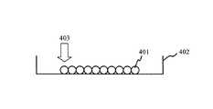
図4に、バッチ法により製作した多数のプローブビーズを、一次元または二次元状に整列させ、分光分析法により1個ずつ品質検査するための方法を示す概念図を示す。バッチ法により製作したプローブビーズ401を、容器402の底面に一次元または二次元状に配列する。プローブビーズ401に励起光403を照射し、分光分析法により、容器402の底面に配列されたプローブビーズ401の品質を検査する。このとき、励起光403を一次元または二次元状に掃引しながらプローブビーズ401の品質を1個ずつ検査してもよい、また励起光403の照射範囲を広くして、幾つかのプローブビーズ401の品質を一括して検査してもよい。 FIG. 4 is a conceptual diagram showing a method for aligning a large number of probe beads produced by a batch method in a one-dimensional or two-dimensional manner and inspecting quality one by one by spectroscopic analysis. Probe
品質検査の結果、すべてのプローブビーズ401の中から、不良品と判定された不良品プローブビーズを取り除き、良品と判定された良品プローブビーズだけを残す。すべてのプローブビーズ401の中から不良品プローブビーズだけを選択的に取り除く方法として、微小なエアピンセットを用いる方法や、レーザー光を用いた光ピンセットを用いる方法などがある。すべてのプローブビーズ401の中から、不良品プローブビーズを取り除き、容器402の中に残った良品プローブビーズのみをキャピラリビーズアレイに供する。 As a result of the quality inspection, defective probe beads determined to be defective are removed from all
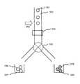
図5に、バッチ法にて製作したプローブビーズを、フローサイトメーターの原理に基づいて、分光分析法により1個ずつ品質検査し、良品プローブビーズと不良品プローブビーズを選別するための方法を概念図で示す。プローブビーズ501をフローサイトメーターに導入し、フローサイトメーターのフローセル502内にプローブビーズ501を1個ずつフローする。プローブビーズ501に励起光503を照射し、分光分析法によりプローブビーズ501の品質を検査する。フローセル502の下流に検出器504を設置し、プローブビーズ501の品質検査の結果を電気的信号として検出する。フローセル502の下流は分岐しており、バルブ505により流路を切り替えられる。プローブビーズ501の品質検査の結果、プローブビーズ501が良品プローブビーズと判定された場合は、検出器により電気的信号を検出し、バルブ505を切替え、良品プローブビーズ506を良品プローブビーズ回収容器507に流し入れて回収する。また、プローブビーズ501の品質検査の結果、プローブビーズ501が不良品プローブビーズ508と判定された場合は、検出器504により電気的信号を検出し、バルブ505を切り替えて、不良品プローブビーズ508を不良品プローブビーズ回収容器509に流し入れて回収する。良品プローブビーズ回収容器507に回収された良品プローブビーズ506だけを、キャピラリビーズアレイのプローブビーズとして供する。 Fig. 5 shows the concept of a method for screening probe beads produced by the batch method one by one by spectroscopic analysis based on the principle of the flow cytometer, and selecting good probe beads and defective probe beads. Shown in the figure. The
図6に、バッチ法により製作したプローブビーズを、軟質樹脂などに形成されたキャピラリに配列した後に、キャピラリの外側から、キャピラリの内側に配列されたプローブビーズを分光分析することにより、プローブビーズの品質検査を行う方法の概念図を示す。キャピラリ601にプローブビーズ602を配列する。キャピラリ601の外側から、キャピラリ601の内側に配列されたプローブビーズ602に対して励起光603を照射し、分光分析法によりプローブビーズ602の品質を検査する。キャピラリビーズアレイにおいて、キャピラリ内に不良品プローブビーズがあってはならない。従って、キャピラリビーズアレイの品質検査により、不良品プローブビーズが1個でも発見された場合、該不良品プローブビーズを含むキャピラリビーズアレイを不良品と見なし、ユーザには提供しないものとする。 In FIG. 6, after arranging probe beads manufactured by the batch method in a capillary formed in a soft resin or the like, the probe beads arranged on the inside of the capillary are analyzed from the outside of the capillary by spectroscopic analysis. The conceptual diagram of the method of performing quality inspection is shown. Probe
キャピラリビーズアレイでは、キャピラリ中に配列されたプローブビーズと、実験試料中に含まれるターゲット分子の化学反応を検出する。キャピラリビーズアレイを用いた生化学実験の再現性を高めるためには、キャピラリ中に配列されたプローブビーズが均質かつ高品質である必要がある。従って、バッチ法により製作されたすべてのプローブビーズの品質を検査し、所定の品質基準を満たす良品プローブビーズだけを、キャピラリビーズアレイに供することが必要である。 In the capillary bead array, the chemical reaction between the probe beads arranged in the capillary and the target molecules contained in the experimental sample is detected. In order to improve the reproducibility of biochemical experiments using a capillary bead array, the probe beads arranged in the capillary must be homogeneous and of high quality. Therefore, it is necessary to inspect the quality of all the probe beads manufactured by the batch method, and to provide only the good probe beads satisfying the predetermined quality standard to the capillary bead array.
本発明によれば、バッチ法により製作した多数のプローブビーズを、分光分析法を用いて1個ずつ、迅速かつ非破壊的に検査することができる。プローブビーズの品質をキャピラリに配列する前に検査すれば、予め不良品プローブビーズを取り除くことにより、キャピラリに良品プローブビーズだけを配列することができる。また、プローブビーズの品質をキャピラリに配列した後に検査すれば、不良品プローブビーズが配列されているキャピラリビーズアレイを不良品として取り除くことができる。 According to the present invention, a large number of probe beads manufactured by a batch method can be inspected quickly and non-destructively one by one using a spectroscopic analysis method. If the quality of the probe beads is inspected before arranging them in the capillaries, it is possible to arrange only good probe beads in the capillaries by removing defective probe beads in advance. Further, if the quality of the probe beads is inspected after being arranged in the capillaries, the capillary bead array in which the defective probe beads are arranged can be removed as a defective product.
従って、本発明によって、不良なキャピラリビーズアレイの発生を検知しこれを取り除くことにより、ユーザに均質かつ高品質のキャピラリビーズアレイだけを供給することができる。従って、キャピラリビーズアレイを用いた生化学実験の再現性を大幅に向上させ、ユーザにとっての付加価値を大幅に向上させることができる。 Therefore, according to the present invention, only the homogeneous and high-quality capillary bead array can be supplied to the user by detecting the occurrence of a defective capillary bead array and removing it. Therefore, the reproducibility of the biochemical experiment using the capillary bead array can be greatly improved, and the added value for the user can be greatly improved.
101・・・プローブビーズ、102・・・励起光、103・・・プローブ、
201・・・プローブビーズ、202・・・プローブ、203・・・標識分子、
301・・・プローブビーズ、302・・・励起光、303・・・プローブ、
401・・・プローブビーズ、402・・・容器、403・・・励起光、
501・・・プローブビーズ、502・・・フローサイトメーターのフローセル、503・・・励起光、504・・・検出器、505・・・バルブ、506・・・良品プローブビーズ、507・・・良品プローブビーズ回収容器、508・・・不良品プローブビーズ、509・・・不良品プローブビーズ回収容器、
601・・・キャピラリ、602・・・プローブビーズ、603・・・励起光。101 ... probe beads, 102 ... excitation light, 103 ... probes,
201 ... probe beads, 202 ... probes, 203 ... labeled molecules,
301 ... probe beads, 302 ... excitation light, 303 ... probes,
401 ... probe beads, 402 ... container, 403 ... excitation light,
501 ... probe beads, 502 ... flow cell of flow cytometer, 503 ... excitation light, 504 ... detector, 505 ... valve, 506 ... good probe beads, 507 ... good Probe bead collection container, 508... Defective probe bead, 509... Defective probe bead collection container,
601 ... capillary, 602 ... probe beads, 603 ... excitation light.
Claims (11)
Translated fromJapaneseバッチ法により一括して製作した多数のプローブビーズのビーズとプローブの結合状況を、分光分析法を用いて1個ずつ検査することを特徴とする、キャピラリビーズアレイのプローブビーズの品質検査方法。Quality inspectionof individual probe beadsin a capillary bead arrayin which a large number of one-dimensional or two-dimensional probe beads are bonded to the surface of a probe molecule that has the property of capturing target molecules. A method,
A method for inspecting the quality of probe beads in a capillary bead array, in which the binding state of a large number of probe beads and probes manufactured in batch by a batch method is inspected one by one using a spectroscopic analysis method.
Priority Applications (3)
| Application Number | Priority Date | Filing Date | Title |
|---|---|---|---|
| JP2005152254AJP4520361B2 (en) | 2005-05-25 | 2005-05-25 | Probe bead quality inspection method |
| EP06010072AEP1726941A3 (en) | 2005-05-25 | 2006-05-16 | Method for inspecting the quality of probe beads |
| US11/435,940US20060270054A1 (en) | 2005-05-25 | 2006-05-18 | Method for inspecting the quality of probe beads |
Applications Claiming Priority (1)
| Application Number | Priority Date | Filing Date | Title |
|---|---|---|---|
| JP2005152254AJP4520361B2 (en) | 2005-05-25 | 2005-05-25 | Probe bead quality inspection method |
Publications (2)
| Publication Number | Publication Date |
|---|---|
| JP2006329756A JP2006329756A (en) | 2006-12-07 |
| JP4520361B2true JP4520361B2 (en) | 2010-08-04 |
Family
ID=36931833
Family Applications (1)
| Application Number | Title | Priority Date | Filing Date |
|---|---|---|---|
| JP2005152254AExpired - Fee RelatedJP4520361B2 (en) | 2005-05-25 | 2005-05-25 | Probe bead quality inspection method |
Country Status (3)
| Country | Link |
|---|---|
| US (1) | US20060270054A1 (en) |
| EP (1) | EP1726941A3 (en) |
| JP (1) | JP4520361B2 (en) |
Families Citing this family (2)
| Publication number | Priority date | Publication date | Assignee | Title |
|---|---|---|---|---|
| US10829815B2 (en) | 2017-11-17 | 2020-11-10 | 10X Genomics, Inc. | Methods and systems for associating physical and genetic properties of biological particles |
| EP3938537A1 (en)* | 2019-03-11 | 2022-01-19 | 10X Genomics, Inc. | Systems and methods for processing optically tagged beads |
Family Cites Families (14)
| Publication number | Priority date | Publication date | Assignee | Title |
|---|---|---|---|---|
| US5093234A (en)* | 1984-12-24 | 1992-03-03 | Caribbean Microparticles Corporation | Method of aligning, compensating, and calibrating a flow cytometer for analysis of samples, and microbead standards kit therefor |
| US5620842A (en)* | 1995-03-29 | 1997-04-15 | Becton Dickinson And Company | Determination of the number of fluorescent molecules on calibration beads for flow cytometry |
| ATE496288T1 (en)* | 1995-10-11 | 2011-02-15 | Luminex Corp | SIMULTANEOUS MULTIPLE ANALYSIS OF CLINICAL SAMPLES |
| US5747349A (en)* | 1996-03-20 | 1998-05-05 | University Of Washington | Fluorescent reporter beads for fluid analysis |
| JP3944996B2 (en)* | 1998-03-05 | 2007-07-18 | 株式会社日立製作所 | DNA probe array |
| US20020150909A1 (en)* | 1999-02-09 | 2002-10-17 | Stuelpnagel John R. | Automated information processing in randomly ordered arrays |
| CN1245520C (en)* | 1999-04-12 | 2006-03-15 | 日立化成工业株式会社 | Method for producing probe arrays for biological materials using fine particles |
| CA2400789A1 (en)* | 2000-02-22 | 2001-08-30 | Genospectra, Inc. | Microarray fabrication techniques and apparatus |
| US6649419B1 (en)* | 2000-11-28 | 2003-11-18 | Large Scale Proteomics Corp. | Method and apparatus for protein manipulation |
| JP3899831B2 (en)* | 2001-03-02 | 2007-03-28 | 株式会社日立製作所 | Biochemical sensor and biochemical inspection apparatus using the same |
| DE10142643A1 (en)* | 2001-08-31 | 2003-04-24 | Clondiag Chip Tech Gmbh | Detection of interactions on probe arrays |
| JP2004085556A (en)* | 2002-06-28 | 2004-03-18 | Canon Inc | Method for manufacturing probe carrier, manufacturing apparatus and quality assurance method |
| JP2005117943A (en)* | 2003-10-15 | 2005-05-12 | Takara Bio Inc | Method for analyzing gene expression |
| JP4344624B2 (en)* | 2004-02-02 | 2009-10-14 | 日立ソフトウエアエンジニアリング株式会社 | Bead position information identification method |
- 2005
- 2005-05-25JPJP2005152254Apatent/JP4520361B2/ennot_activeExpired - Fee Related
- 2006
- 2006-05-16EPEP06010072Apatent/EP1726941A3/ennot_activeWithdrawn
- 2006-05-18USUS11/435,940patent/US20060270054A1/ennot_activeAbandoned
Also Published As
| Publication number | Publication date |
|---|---|
| EP1726941A2 (en) | 2006-11-29 |
| EP1726941A3 (en) | 2008-06-04 |
| US20060270054A1 (en) | 2006-11-30 |
| JP2006329756A (en) | 2006-12-07 |
Similar Documents
| Publication | Publication Date | Title |
|---|---|---|
| Ruzicka et al. | Peer Reviewed: From Flow Injection to Bead Injection. | |
| US7057732B2 (en) | Imaging platform for nanoparticle detection applied to SPR biomolecular interaction analysis | |
| Cretich et al. | Digital detection of biomarkers assisted by nanoparticles: application to diagnostics | |
| KR101361652B1 (en) | Raman assay-based High Throughput multiplex drug screening apparatus | |
| EP2147295B1 (en) | Sers nanotag assays | |
| JP7334978B2 (en) | Nanosensor method and apparatus for analyte determination | |
| EP3353548B1 (en) | Biosensor and use thereof | |
| US20120202296A1 (en) | System, method, and apparatus for measuring affinity constants | |
| EP4446727A1 (en) | Method for generating spectral data pertaining to microparticle sample, method for analyzing microparticles, method for distinguishing microparticles, method for assessing whether cancer-cell-derived exosomes are present, substrate for measuring spectrum of microparticles, device for measuring spectrum of microparticles, and apparatus for measuring spectrum of microparticles | |
| KR20150107231A (en) | A microplate having well with membrane | |
| JP4732913B2 (en) | Microchip and method of using microchip | |
| JP4118281B2 (en) | Fluorescence sensor based on multi-channel structure | |
| JP4520361B2 (en) | Probe bead quality inspection method | |
| WO2016088236A1 (en) | Method for analyzing components in liquid sample | |
| JP2006030155A (en) | Plate assay using spectroscopy | |
| CN110554178A (en) | Suspension type liquid biochip detection method | |
| US20250198927A1 (en) | Method and device for the marker-free detection of an analyte | |
| Sun | Label-free sensing on microarrays | |
| JP4632156B2 (en) | Analysis method using fluorescence depolarization | |
| JP2005337805A (en) | Antibody or antigen measuring method | |
| Hosoi et al. | Development of microreactor array chip‐based measurement system for massively parallel analysis of enzymatic activity | |
| JP4671084B2 (en) | Electrode for dielectrophoresis apparatus, method for producing the same, dielectrophoresis apparatus, and method for separating and detecting substance using the electrode | |
| Dias et al. | One-step trapping of droplets and surface functionalization of sensors using gold-patterned structures for multiplexing in biochips | |
| Silpa et al. | Review on Microfluidic Surface Plasmon Resonance-Based Chip for Monitoring Biomechanisms | |
| WO2004102160A2 (en) | Imaging platform for nanoparticle detection applied to spr biomolecular interaction analysis |
Legal Events
| Date | Code | Title | Description |
|---|---|---|---|
| A621 | Written request for application examination | Free format text:JAPANESE INTERMEDIATE CODE: A621 Effective date:20071221 | |
| A977 | Report on retrieval | Free format text:JAPANESE INTERMEDIATE CODE: A971007 Effective date:20100209 | |
| A131 | Notification of reasons for refusal | Free format text:JAPANESE INTERMEDIATE CODE: A131 Effective date:20100323 | |
| A521 | Request for written amendment filed | Free format text:JAPANESE INTERMEDIATE CODE: A523 Effective date:20100420 | |
| TRDD | Decision of grant or rejection written | ||
| A01 | Written decision to grant a patent or to grant a registration (utility model) | Free format text:JAPANESE INTERMEDIATE CODE: A01 Effective date:20100518 | |
| A01 | Written decision to grant a patent or to grant a registration (utility model) | Free format text:JAPANESE INTERMEDIATE CODE: A01 | |
| A61 | First payment of annual fees (during grant procedure) | Free format text:JAPANESE INTERMEDIATE CODE: A61 Effective date:20100520 | |
| FPAY | Renewal fee payment (event date is renewal date of database) | Free format text:PAYMENT UNTIL: 20130528 Year of fee payment:3 | |
| R150 | Certificate of patent or registration of utility model | Free format text:JAPANESE INTERMEDIATE CODE: R150 | |
| FPAY | Renewal fee payment (event date is renewal date of database) | Free format text:PAYMENT UNTIL: 20130528 Year of fee payment:3 | |
| FPAY | Renewal fee payment (event date is renewal date of database) | Free format text:PAYMENT UNTIL: 20160528 Year of fee payment:6 | |
| LAPS | Cancellation because of no payment of annual fees |