JP4519667B2 - Sample rack transport device - Google Patents
Sample rack transport deviceDownload PDFInfo
- Publication number
- JP4519667B2 JP4519667B2JP2005023133AJP2005023133AJP4519667B2JP 4519667 B2JP4519667 B2JP 4519667B2JP 2005023133 AJP2005023133 AJP 2005023133AJP 2005023133 AJP2005023133 AJP 2005023133AJP 4519667 B2JP4519667 B2JP 4519667B2
- Authority
- JP
- Japan
- Prior art keywords
- sample rack
- rack
- control box
- housing
- unit
- Prior art date
- Legal status (The legal status is an assumption and is not a legal conclusion. Google has not performed a legal analysis and makes no representation as to the accuracy of the status listed.)
- Expired - Fee Related
Links
Images


Classifications
- G—PHYSICS
- G01—MEASURING; TESTING
- G01N—INVESTIGATING OR ANALYSING MATERIALS BY DETERMINING THEIR CHEMICAL OR PHYSICAL PROPERTIES
- G01N35/00—Automatic analysis not limited to methods or materials provided for in any single one of groups G01N1/00 - G01N33/00; Handling materials therefor
- G01N35/02—Automatic analysis not limited to methods or materials provided for in any single one of groups G01N1/00 - G01N33/00; Handling materials therefor using a plurality of sample containers moved by a conveyor system past one or more treatment or analysis stations
- G01N35/026—Automatic analysis not limited to methods or materials provided for in any single one of groups G01N1/00 - G01N33/00; Handling materials therefor using a plurality of sample containers moved by a conveyor system past one or more treatment or analysis stations having blocks or racks of reaction cells or cuvettes
- G—PHYSICS
- G01—MEASURING; TESTING
- G01N—INVESTIGATING OR ANALYSING MATERIALS BY DETERMINING THEIR CHEMICAL OR PHYSICAL PROPERTIES
- G01N35/00—Automatic analysis not limited to methods or materials provided for in any single one of groups G01N1/00 - G01N33/00; Handling materials therefor
- G01N35/02—Automatic analysis not limited to methods or materials provided for in any single one of groups G01N1/00 - G01N33/00; Handling materials therefor using a plurality of sample containers moved by a conveyor system past one or more treatment or analysis stations
- G01N35/04—Details of the conveyor system
- G01N2035/0496—Other details
- G01N2035/0498—Drawers used as storage or dispensing means for vessels or cuvettes
Landscapes
- Chemical & Material Sciences (AREA)
- Chemical Kinetics & Catalysis (AREA)
- Physics & Mathematics (AREA)
- Health & Medical Sciences (AREA)
- Life Sciences & Earth Sciences (AREA)
- Analytical Chemistry (AREA)
- Biochemistry (AREA)
- General Health & Medical Sciences (AREA)
- General Physics & Mathematics (AREA)
- Immunology (AREA)
- Pathology (AREA)
- Automatic Analysis And Handling Materials Therefor (AREA)
Description
Translated fromJapanese本発明は、検体が収容された容器を保持する検体ラックを搬送する検体ラック搬送装置に関する。 The present invention relates to a sample rack transport apparatus that transports a sample rack that holds a container in which a sample is stored.
病院や検査センターなどの臨床検査室で実施される血液検査や尿検査等では、近年の検体処理数及び検査における分析項目数の増加によって、その効率化が求められている。そこで、大量の検体検査を効率的に行うために、血液や尿などの検体が収容された検体容器を保持した検体ラックを血球検査装置、尿検査装置等の分析装置に順次搬送する検体ラック搬送装置が用いられている(例えば、特許文献1参照)。 In blood tests, urine tests, and the like performed in clinical laboratories such as hospitals and test centers, there has been a demand for higher efficiency due to the recent increase in the number of specimens processed and the number of analysis items in tests. Therefore, in order to efficiently perform a large amount of sample tests, the sample rack transports a sample rack holding a sample container holding a sample such as blood or urine sequentially to an analyzer such as a blood cell test apparatus or a urine test apparatus. An apparatus is used (for example, see Patent Document 1).
この特許文献1に開示された検体ラック搬送装置は、検体ラックを搬送する搬送機構とこれを載せて支持する架台(筐体)と搬送機構の動作を制御する制御部とで備えており、制御部は、架台の内部に設けられている。 The sample rack transport apparatus disclosed in
このような検体ラック搬送装置では、保守・点検作業を行う際に、主電源を落とした後、制御部を露出させる必要がある。しかしながら、前述した検体ラック搬送装置にあっては、制御部を露出させるために、架台に設けられた側板や搬送機構を取り外す必要があり、装置の保守・点検の工数が嵩むという問題があった。 In such a sample rack transport apparatus, it is necessary to expose the control unit after the main power is turned off when performing maintenance / inspection work. However, in the sample rack transport apparatus described above, it is necessary to remove the side plate and the transport mechanism provided on the gantry in order to expose the control unit, and there is a problem that man-hours for maintenance and inspection of the apparatus increase. .
本発明は、かかる事情に鑑みてなされたものであり、従来に比して、保守、点検等の作業を容易とすることが可能な検体ラック搬送装置を提供することを目的とする。 The present invention has been made in view of such circumstances, and an object of the present invention is to provide a sample rack transport apparatus capable of facilitating maintenance, inspection, and the like as compared with the prior art.
本発明に係る検体ラック搬送装置は、臨床検体が収容された容器を保持する検体ラックを分析装置に搬送するための検体ラック搬送装置であって、分析前の検体ラックをストックするためのスタートストッカ、スタートストッカにストックされた検体ラックを分析装置に搬送するための搬送路、および、分析装置で分析を終えた検体ラックをストックするためのエンドストッカを上面に備えた筺体と、スタートストッカにストックされた検体ラックを搬送路に移動させ、搬送路に移動した検体ラックを分析装置に搬送するとともに分析を終えた検体ラックをエンドストッカに移動させる搬送機構部と、搬送機構部の動作を制御する制御部と、制御部を収納する制御ボックスと、を備え、搬送機構部及び制御ボックスが筐体の内部に配置され、搬送機構部が筺体上面のスタートストッカ、搬送路およびエンドストッカの下方に配置され、且つ、制御ボックスが搬送機構部の下方に配置されており、制御ボックスが筐体の一側面から引き出し状に出し入れ可能に構成されていることを特徴とする。Sample rack transport system according to the present invention,clinical specimens a sample rack transporting apparatusfor transportinga analyzer sample rack for holding the accommodation containers,start to stock a sample rack prior to analysis stocker , A transport path for transporting the sample rack stocked in the start stocker to the analyzer, a housing equipped with an end stocker for stocking the sample rack that has been analyzed by the analyzer, and a stock in the start stocker The sample rack moved to the transport path, transports the sample rack moved to the transport path to the analyzer, and moves the sample rack after analysis to the end stocker, and controls the operation of the transport mechanism section. a control unit, and a control box for accommodating a control unit,the transport mechanism and the control box is placed inside the housing, Start stocker mechanism feeding the housing upper surface is disposed below the transport path and Endosutokka, and, outthe control box is disposed below the conveyance mechanism, the controlbox fromone side of the housing in a drawer-like It is configured to be possible.
このようにすることにより、前記制御ボックスを前記筐体から引き出すだけで前記制御部を露出させることができ、従来に比して、保守・点検等の作業が容易となり、保守工数を低減できる。 In this way, the control unit can be exposed only by pulling out the control box from the housing, and maintenance / inspection work can be facilitated and maintenance man-hours can be reduced as compared with the conventional case.
上記発明においては、制御ボックスは、上部が開放された扁平な箱状であることが好ましい。In the said invention, it is preferable that acontrol box is a flat box shape by which the upper part was open | released.
上記発明においては、前記搬送機構部と前記制御ボックスとの間に設けられ、上面が窪んだ凹状受部をさらに備える構成とされていることが好ましい。 In the said invention, it is preferable to set it as the structure further provided with the concave receiving part which was provided between the said conveyance mechanism part and the said control box, and the upper surface was depressed.
このようにすることにより、検体ラック搬送中に検体容器から検体が漏出した場合に、漏出した検体が搬送機構部の下側の制御部に到達するのを防ぎ、装置の故障等を防止することができる。 In this way, when a sample leaks from the sample container during sample rack transportation, the leaked sample is prevented from reaching the lower control unit of the transport mechanism unit, thereby preventing a failure of the apparatus. Can do.
上記発明においては、搬送機構部は、アクチュエータを有し、当該アクチュエータの動作によって、検体ラックを移動させるように構成されており、制御ボックスの筐体への挿入方向の端部に設けられ、前記制御部へつながる配線が接続されている制御ボックス側コネクタと、筐体に設けられ、制御ボックス側コネクタと接続可能であって、アクチュエータへつながる配線が接続されている筐体側コネクタとをさらに備え、制御ボックス側コネクタ及び筐体側コネクタは、制御ボックスが筐体に挿入された場合に互いに接続される位置に夫々配されていることが好ましい。なお、ここでいうアクチュエータとは、電気エネルギー、熱エネルギー、化学エネルギー及び圧力などを機械的な運動に変換する装置をいう(例えば、モータ、ソレノイド、エアシリンダー)。In the above invention, the transport mechanism section includes an actuator, and is configured tomove the sample rack by the operation of the actuator. The transport mechanism section is provided at an end of the control box in the direction of insertion into the housing. andTei Ru control box connector wiring is connected leading to the control unit, provided in the housing, be connectable to the control box connector, leading to the actuator wires are connected further comprises a housing-side connector and RuTei, The control box side connector and the housing side connector are preferably arranged at positions where they are connected to each other when the control box is inserted into the housing. The actuator here refers to a device that converts electrical energy, thermal energy, chemical energy, pressure, and the like into mechanical motion (eg, motor, solenoid, air cylinder).
このようにすることにより、制御ボックスを出し入れするだけで、制御部と搬送機構部間の切断・接続が容易となる。 By doing so, the disconnection / connection between the control unit and the transport mechanism unit is facilitated only by inserting and removing the control box.
上記発明においては、制御ボックス側コネクタ及び筺体側コネクタは、それぞれ2組以下設けられていることが好ましい。In the said invention, it is preferablethat two or less sets of thecontrol box side connector and the housing side connector areprovidedrespectively .
このようにすることにより、接続されるコネクタの数が少ないので、筐体への制御ボックスの挿入が容易となる。また、検体ラック搬送装置の組立において、高い組立精度を必要としない。 In this way, since the number of connectors to be connected is small, the control box can be easily inserted into the housing. Moreover, high assembly accuracy is not required in the assembly of the sample rack transport apparatus.
上記発明においては、アクチュエータへつながる配線が接続されているアクチュエータ側コネクタと、アクチュエータ側コネクタに接続することが可能であり、筐体側コネクタへつながる配線が接続されているアクチュエータ接続用コネクタと、アクチュエータ接続用コネクタ及び筐体側コネクタが設けられている筐体側中継基板とをさらに備え、アクチュエータ接続用コネクタは、対応するアクチュエータと近接した位置に配されていることが好ましい。In the above invention, the actuator side connector wiring RuTei is connected leading to the actuator, it is possible to connect to the actuator side connector, and the actuator connector RuTei wiring connected to the case side connector are connected, the actuator connection It is preferable to further include a housing-side relay board on which the connector for the housing and the housing-side connector are provided, and the connector for connecting the actuator is disposed at a position close to the corresponding actuator.
このようにすることにより、各アクチュエータへの配線が短くなり、配線の取り扱いが容易となる。 By doing so, the wiring to each actuator is shortened, and the handling of the wiring becomes easy.
上記発明においては、前記配線には、前記搬送機構部に設けられた複数の電力供給対象へ夫々電力を供給するための電源線が含まれており、前記制御部は、各電力供給対象へ夫々電力を供給する電源部をさらに備え、前記電源線は、前記電源部から前記制御ボックス側コネクタまでの間において、前記電力供給対象の数よりも少ない数だけ設けられ、前記アクチュエータ側コネクタから前記複数の電力供給対象へと夫々つなげられていることが好ましい。 In the above invention, the wiring includes a power line for supplying power to each of a plurality of power supply targets provided in the transport mechanism, and the control unit supplies each power supply target to each power supply target. The power supply unit further includes a power supply unit that supplies power, and the power supply line is provided between the power supply unit and the control box side connector by a number smaller than the number of power supply targets, It is preferable to be connected to each of the power supply targets.
このようにすることにより、配線数を減少させることができ、配線の取り扱いが容易となる。 By doing so, the number of wires can be reduced, and the handling of the wires becomes easy.
上記発明においては、前記筐体側中継基板は、前記制御部からの電気信号を用いて、前記アクチュエータを駆動するドライバ回路を有することが好ましい。 In the above invention, it is preferable that the housing-side relay board has a driver circuit that drives the actuator using an electric signal from the control unit.
このようにすることにより、新規にドライバ回路を増設する必要が生じた場合に、制御部を再設計する必要が無いので、開発工数・費用を低減させることができる。 In this way, when it is necessary to newly add a driver circuit, it is not necessary to redesign the control unit, so that it is possible to reduce development man-hours and costs.
上記発明においては、制御部へつながる配線が接続されている制御部側コネクタと、制御部側コネクタと接続することが可能であり、制御ボックス側コネクタへつながる配線が接続されている制御部接続用コネクタと、制御部接続用コネクタ及び制御ボックス側コネクタが設けられている制御ボックス側中継基板とをさらに備えることが好ましい。In the above invention, andTei Ru controller connector wiring is connected leading to the control unit, may be connected to the control unit side connector, control box side line connected to the connector is connectedTei Ru controller connected It is preferable to further include a connector and a control box side relay board provided with a control unit connection connector and a control box side connector.
また、上記発明においては、制御部が複数の基板で構成されることが好ましい。 Moreover, in the said invention, it is preferable that a control part is comprised with a some board | substrate.
このようにすることにより、制御部の機能を複数に分割し、当該機能別に基板を構成することが可能となる。このため、基板の一部を変更するだけで、さまざまな設計仕様を実現することが容易となる。 By doing so, it is possible to divide the function of the control unit into a plurality of parts and to configure a substrate for each function. For this reason, it becomes easy to realize various design specifications only by changing a part of the substrate.
上記発明においては、前記制御ボックスが磁性体で構成されていることが好ましい。 In the said invention, it is preferable that the said control box is comprised with the magnetic body.
このようにすることにより、制御部からの放射ノイズを低減させることができ、電磁波による作業環境への影響を低減することができる。 By doing in this way, the radiation noise from a control part can be reduced and the influence on the work environment by electromagnetic waves can be reduced.
上記発明においては、制御ボックスは、筺体の一側面側に設けられた取手をさらに備える構成であることが好ましい。
In the said invention, it is preferable that acontrol box is further equipped with the handle provided inthe one side surface of the housing .
このようにすることにより、制御ボックスを引き出すことが容易となり、作業性を向上させることができる。 By doing in this way, it becomes easy to pull out a control box and workability | operativity can be improved.
本発明に係る検体ラック搬送装置によれば、前記制御ボックスを前記筐体から引き出すだけで前記制御部を露出させることができ、従来に比して、修理等の保守の作業が容易となり、保守工数を低減できる等、本発明は優れた効果を奏する。 According to the sample rack transport device of the present invention, the control unit can be exposed by simply pulling out the control box from the housing, and maintenance work such as repair becomes easier than in the prior art. The present invention has excellent effects such as reduction of man-hours.
以下、本発明の実施の形態に係る検体ラック搬送装置について、図面を参照しながら具体的に説明する。 Hereinafter, a sample rack transport apparatus according to an embodiment of the present invention will be specifically described with reference to the drawings.
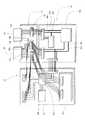
図1は、本発明の実施の形態に係る検体ラック搬送装置100の全体構成を示す外観斜視図であり、図2は、検体ラック搬送装置100の上部の構成を示す平面図である。図1に示すように、検体ラック搬送装置100は、検体ラックを搬送する搬送機構部16と、搬送機構部16の動作等を制御する制御部18を搭載した制御ボックス19と、それらを保持する筐体20とで主として構成されている。図2に示すように、検体ラック搬送装置100は、血液分析装置9に接続され、その血液分析装置9に血液検体を供給することが可能なように構成されている。血液検体は、以下に説明するような検体容器に収容され、かかる複数の検体容器が後述するような検体ラックに保持される。このような検体ラックが、検体ラック搬送装置100によって搬送される。 FIG. 1 is an external perspective view showing an overall configuration of a sample
図3は、血液検体を収容するための検体容器の外観を示す斜視図であり、図4は、血液検体を収容するための検体ラックの外観を示す斜視図である。図4に示すように、検体容器14は、血液検体を収容することが可能なように、一端を閉じて丸底にした細長い管状になっており、その側面には、検体のID番号等の情報を示すバーコードが印刷されたバーコードラベル13が貼付されている。また、図4に示すように、この検体ラック搬送装置100で用いる検体ラック12は、複数の検体容器14を列状に保持することが可能な形状となっている。 FIG. 3 is a perspective view showing an appearance of a sample container for containing a blood sample, and FIG. 4 is a perspective view showing an appearance of a sample rack for containing a blood sample. As shown in FIG. 4, the
図1に示すように、筐体20は、概ね立方体状に形成されている。その上部は一部が凹状に窪んでおり、ここに分析前の検体ラック12が複数ストックされるスタートストッカ21と、検体ラック12を血液分析装置9に供給する位置に搬送するための搬送路22と、分析を終えた検体ラック12がストックされるエンドストッカ23とが形成されている。このようなスタートストッカ21、搬送路22及びエンドストッカ23の下側には、搬送機構部16が配置されている。 As shown in FIG. 1, the housing |
搬送機構部16は、ラック引き込み用ベルト24、T字型レバー26、爪部29a、29b、37及び突起部32を有している。かかる搬送機構部16は、複数のモータとモータの回転運動を直線運動に変換する変換機構とを備えている。前記変換機構は、例えば、モータの駆動軸に備えられた駆動プーリ、従動プーリ及びそれらのプーリに張架されたタイミングベルト等から構成され、モータの回転運動を直線運動に変換する。このような変換機構とモータとが連動することにより、ラック引き込み用ベルト24、T字型レバー26、爪部29a、29b、37、及び突起部32が各別に駆動される。 The
図2に示すように、スタートストッカ21とエンドストッカ23とは、互いに所定の距離だけ離隔して配置されている(以下、この離隔方向を左右方向といい、この方向と垂直な方向を前後方向という。なお、検体ラック搬送装置100に対して血液分析装置9が配置される方向を「後方」、その逆方向を「前方」という。さらに、この「後方」を向いたときの右方向を「右方」、左方向を「左方」という)。検体ラック12は左右方向にその長尺方向が合わせられ、検体ラック搬送装置100上を終始その向きで搬送される。スタートストッカ21はエンドストッカ23の右側に設けられている。 As shown in FIG. 2, the
スタートストッカ21は底面21a、側壁21A、21B、27及び22Dを備えており、同様にエンドストッカ23は、底面23a、側壁23A、23B、36及び22Dを備えている。かかる底面21a及び底面23aの形状は、前後に長い長方形であり、底面21a及び底面23aの幅は、ともに検体ラックの左右方向の長さと概ね同等である。底面21aの左右端には側壁21A、21Bが、前端には側壁27が、後端には側壁22Dが夫々設けられている。これにより、スタートストッカ21は、筐体20の上面よりも一段低い凹状に形成されている。側壁22Dは、スタートストッカ21の後端からさらに左方向に延びており、後述する搬送路22及びエンドストッカ23の後端の側壁も兼ねている。同様に、底面23aの左右端には側壁23A、23Bが、前端には側壁36が、後端には側壁22Dが夫々設けられている。これにより、エンドストッカ23は、筐体20の上面よりも一段低い凹状に形成されている。 The
スタートストッカ21からエンドストッカ23に検体ラックを搬送するための搬送路22は、側壁22Dに沿って形成されている。スタートストッカ21の底面21aからエンドストッカ23の底面23aに至る搬送路22は、検体ラック12を滑らせながら送ることができるように平坦になっている。 A
スタートストッカ21の後端部の側壁22Dに臨む位置がラック横送り初期位置22Aであり、スタートストッカ21の前端の側壁27に臨む位置がラック導入位置24Aである。ラック導入位置24Aには、検体ラック12をスタートストッカに搬入する為のラック引き込み用ベルト24が設けられている。このラック引き込み用ベルト24によって、ラック導入位置24Aに検体ラック12を外部の供給元から導入することができる。側壁21Aの前端部には、検体ラックの有無を検出するセンサ25が設けられており、センサ25は、検体ラック12がラック導入位置24Aに存在するか否かを検出し、その検出信号を制御部18に出力する。図1に示すように、側壁27には左右方向に細長いスリット(図示せず)が形成されており、このスリットから出し入れ可能なようにT字型レバー26が設けられている。このT字型レバー26は、ラック導入位置24Aに検体ラック12を導入する場合には、導入の妨げにならないように、側壁27内に収容され、ラック導入位置24Aに検体ラック12が存在する場合には、スリットから後方へ突出され、ラック導入位置24Aにある検体ラック12を後方に押し出すことが可能となっている。図2に示すように、底面21aには、前後方向に細長いスリット28が2つ形成されており、これら2つのスリット28から出し入れ可能なように爪部29aが設けられている。この爪部29aは、スリット28に沿って前後に移動することが可能となっている。従って、爪部29aは、検体ラック12の底部と係合し、この状態で後方へ移動することにより、検体ラックをラック横送り初期位置22Aへ移動させることができる。さらに、ラック横送り初期位置22A付近の側壁22Dには、検体ラック12の有無を検出するセンサ30が設けられている。このセンサ30は、検体ラック12がラック横送り初期位置22Aに存在するか否かを検出し、その検出信号を制御部18に出力する。 The position facing the side wall 22D at the rear end portion of the
搬送路22の中間部は、検体ラック12に保持された検体容器14が血液分析装置に供給される検体供給位置22Bとされている。また、底面22aには、スリット31が左右方向に形成されており、このスリット31から出し入れが可能なように、突起部32が設けられている。この突起部32は、スリット31に沿って左右に移動することが可能となっている。従って、突起部32は検体ラック12の底部と係合し、この状態で左方へ移動することにより、検体ラック12を後述するラック横送り終点位置22Cへ移動させることができるようになっている。 The intermediate portion of the
エンドストッカ23の後端部の側壁22Dに臨む位置は、ラック横送り終点位置22Cであり、エンドストッカ23の前端部の側壁36に臨む位置は、ラック送出位置23Cである。エンドストッカ23の後端部の右側には、検体ラック12の有無を検出するセンサ34が設けられている。このセンサ34は、検体ラック12がラック横送り終点位置22Cに存在するか否かを検出し、その検出信号を制御部18に出力する。 The position facing the side wall 22D at the rear end of the
底面23aには、前後方向に細長いスリット33が2つ形成されており、これら2つのスリット33から出し入れ可能なように爪部29bが設けられている。この爪部29bは、スリット33に沿って前後に移動することが可能となっている。従って、爪部29bは、検体ラック12の底部と係合し、この状態で前方へ移動することにより、検体ラックをラック送出位置23Cへ移動させることができる。側壁36の右端部には、検体ラック12の有無を検出するセンサ35が設けられている。このセンサ35は、検体ラック12がラック送出位置23Cに存在するか否かを検出し、その検出信号を制御部18に出力する。さらに、側壁36には左右方向に細長いスリット(図示せず)が形成されている。また、前記スリットから爪部37が、後方に向かって突出するように設けられている。この爪部37は、スリットに沿って、左右方向に移動が可能である。これにより、爪部37が検体ラック12の右側面を押すことにより、検体ラック12をラック送出位置23Cから左側にある供給先へ搬出することできる。 Two
このような構成とすることにより、まず、ラック引き込み用ベルト24によって、供給元から検体ラック12がラック導入位置24Aに搬入される。ラック導入位置24Aに検体ラック12が到着した場合には、センサ25によって、これが検出される。その後、T字型レバー26が後方へと移動し、検体ラック12がラック1つ分だけ後方へと押される。検体ラック12が後方に移動した後のラック導入位置24Aには、新たに検体ラック12が導入される。更にT字型レバー26により、後から導入された検体ラック12が押動されることにより、先に押し出された検体ラック12が後から押し出された検体ラック12に押されて後方に移動する。この動作を繰り返すことにより、スタートストッカ21内に検体ラック12がストックされていく。そして、爪部29aが突出し、スタートストッカ21内の最も後方の位置にストックされている検体ラック12と係合し、その状態で後方に移動することにより、検体ラック12がラック横送り初期位置22Aに向けて搬送される。 With such a configuration, first, the
ラック横送り初期位置22Aに検体ラック12が到達すると、センサ30によってこれが検出される。この場合には、突起部32が突出し、検体ラック12の底に係合し、この状態で左方向へ移動する。これによって、検体ラック12はラック横送り初期位置22Aからラック横送り終点位置22Cへ向けて搬送される。 When the
ラック横送り終点位置22Cに検体ラック12が到達すると、センサ34によってこれが検出される。この場合には、爪部29bが突出し、ラック横送り終点位置22Cにストックされている検体ラック12と係合し、その状態で前方に移動する。これにより、検体ラック12がラック横送り終点位置22Cからラック送出位置23Cまで搬送される。検体ラック12が移動した後のラック横送り終点位置22Cには、突起部32により、新たに検体ラック12が搬送される。更に爪部29bによって、この検体ラック12は、ラック横送り終点位置22Cからラック送出位置23Cに向かって搬送され、先に搬送された検体ラック12の後側まで到達する。この動作を繰り返すことにより、エンドストッカ23内に検体ラック12がストックされていく。さらに、ラック送出位置23Cに検体ラック12が到着すると、爪部37が検体ラック12の右側面を押しながら移動することにより、検体ラック12が左側にある供給先へ供給される。 When the
このような検体ラック搬送装置100の筐体20の上面には、検体ラック搬送装置の状態等を表示する液晶ディスプレイ40と作業者が搬送装置を操作する為の操作パネル41とが設けられている。これら液晶ディスプレイ40と操作パネル41とは、後述する筐体側中継基板46及び制御ボックス側中継基板45を介して、ユーザインターフェース制御用基板42に接続されている。 On the upper surface of the
図5は、検体ラック搬送装置100の搬送機構部16に設けられたセンサ、モータ及び後述する筐体側中継基板46の配置関係を示す平面図である。図5に示すように、搬送機構部16には、筐体側中継基板46、モータ50、51、52、53、54、55、センサ25、30、34及び35が設けられている。また、中間板17は、搬送機構部16の直下に設けられ、その外側に搬送機構部16がはみ出ないようになっている。さらに、制御ボックス19が筐体20に収容された場合には、制御部18が中間板17の直下に位置し、中間板17の外側に制御ボックス19がはみ出ないようになっている。図6は、検体ラック搬送装置の中間板17の形状を示す斜視図である。図6に示すように、中間板17の縁は上方に向かって折り曲げられ、凹状に形成されている。このような構成により、検体ラック12を搬送中に検体容器14から検体が漏出した場合には、漏出した検体が中間板17で受けられるので、制御ボックス19内に設けられた制御部18に検体が到達することが防止される。 FIG. 5 is a plan view showing the positional relationship between sensors, motors, and a case-
図1に示すように、筐体20の前面下部には、開口部20Aが設けられている。中間板17の下側には、この開口部20Aとつながる空間が形成されており、この空間に、制御ボックス19が収容されるようになっている。筐体20の内部であって、前記空間の両側には、それぞれガイドレール19bが設けられている。前記制御ボックス19の左右両側面には、それぞれ前後方向に長く延びた突起19aが突設されており、突起19aがガイドレール19bに係合した状態で制御ボックス19が前後に移動可能となっている。 As shown in FIG. 1, an
このような構成とすることにより、筐体20から制御ボックス19をスムーズに引き出し、筐体20に制御ボックス19を挿入することが可能となる。さらに、制御ボックス19の前面には、取手56が設けられている。これによって、ユーザは取手56を引くだけで、筐体20から制御ボックス19を容易に引き出すことが可能となる。 With such a configuration, the
また、制御ボックス19及び中間板17は磁性体であるステンレス鋼板により構成されている。これにより、制御ボックス19を筐体20へ収納した場合は、制御部18の周囲を磁性体が覆うこととなり、磁性体が電磁波を吸収することから、制御部18からの放射ノイズを低減させることが可能となる。これによって、電磁波による作業環境への影響を低減することができる。なお、ステンレス鋼以外の炭素鋼、パーマロイ合金、その他の金属又は非金属磁性体を用いて、中間板17を構成してもよい。 Moreover, the
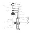
図7は、検体ラック搬送装置100の制御部18の構成を示す図である。制御部18は、上部が開放された箱状の制御ボックス19に収容されている。図7に示すように、制御部18は、ドライバ基板38、CPU基板39、ユーザインターフェース制御用基板42及び制御ボックス側中継基板45を備えている。制御ボックス側中継基板45は、制御ボックス19の後壁に接するように配置されている。また、ドライバ基板38、CPU基板39及びユーザインターフェース制御用基板42は、制御ボックス19内に重ならないように並べて設けられている。ドライバ基板38及びCPU基板39は、相互に電気信号の送受信が可能なように配線コードを介して互いに接続されている。また、CPU基板39の前部には、ユーザインターフェース制御用基板42が載置されている。このユーザインターフェース制御用基板42は、CPU基板39との間で相互にデータ転送が可能であるように、CPU基板39とバス接続されている。このようなユーザインターフェース制御用基板42は、制御ボックス側中継基板45及び筐体側中継基板46を介して、液晶ディスプレイ40及び操作パネル41と接続されている。 FIG. 7 is a diagram illustrating a configuration of the
ドライバ基板38は、モータを駆動することが可能なドライバ回路38A及び商用電源の交流を2種類の電圧の直流に変換する電源回路38Bを有している。なお、このように交流を2種類の電圧の直流に変換するのは、センサ及びCPUが駆動する電圧と、モータ等のアクチュエータが駆動する電圧とが異なっているためである。かかる直流のうちの一方は、センサ及びCPUに供給され、他方は、モータ等のアクチュエータに供給される。ドライバ基板38は、制御ボックス側中継基板45及び筐体側中継基板46を介して、モータ50、51、52、53、54、55、センサ25、30、34及び35と接続されている。これにより、ドライバ基板38は、前記センサから受け取った検出信号をCPU基板39に送信し、また、CPU基板39、前記モータ及びセンサに電力を供給する。さらに、ドライバ基板38は、CPU基板39から受け取ったモータ制御信号に基づいてモータを駆動する。 The
CPU基板39は、CPU39A及びROM39Bを備えており、ROM39Bには、CPU39Aに実行されるコンピュータプログラムが記録されている。CPU基板39は、ドライバ基板38を介して、検出信号及び操作パネル41の出力信号を受信し、CPU39AがROM39Bに記録してあるプログラムを実行する。また、CPU基板39は、前記検出信号及び実行されたプログラムに基づいて、搬送機構部16内に設けられたモータ等のアクチュエータの動作を制御する為のモータ制御信号及び液晶ディスプレイ40に検体ラック搬送装置100の状態を表示させる為の表示用信号を出力するようになっている。 The
ユーザインターフェース制御用基板42は、前記表示用信号に基づいて液晶ディスプレイ40に検体ラック搬送装置100の状態を表示させ、操作パネル41の出力信号をCPU基板39へ送信することが可能となっている。 The user
制御ボックス側中継基板45には、3つの制御部接続用コネクタ43A、43B、43C及び2つの制御ボックス側コネクタ44が設けられている。制御部接続用コネクタ43Aは、CPU基板39及びユーザインターフェース制御用基板42から延びた配線が接続された制御部側コネクタ43aと嵌合しており、制御部接続用コネクタ43Bは、ドライバ基板38、ユーザインターフェース制御用基板42及びCPU基板39から延びた配線が接続された制御部側コネクタ43bと嵌合しており、制御部接続用コネクタ43Cは、ドライバ基板38から延びた配線が接続された制御部側コネクタ43cと嵌合している。これにより、制御ボックス側中継基板45とCPU基板39、ドライバ基板38及びユーザインターフェース制御用基板42とが夫々接続される。 The control box
このような構成にすることにより、制御部18の構成要素であるドライバ基板38、CPU基板39及びユーザインターフェース制御用基板42を検体ラック搬送装置100の設計仕様を満たした他のドライバ基板、CPU基板及びユーザインターフェース基板に置き換えることができる。そのため、これらを再設計する必要がないので、検体ラック搬送装置100の開発工数・費用を低減することが可能となる。 With this configuration, the
なお、ドライバ基板38と制御部接続用コネクタ43B、43Cとを接続する配線コードには、各アクチュエータ及びセンサ等に電力を供給する為の4本の電源線38aが含まれている。センサ駆動用の直流とモータ駆動用の直流とは電圧が異なり、それらはドライバ基板38に設けられた前記電源回路38Bから供給される。 The wiring cord connecting the
制御部接続用コネクタ43A、43B、43Cと制御ボックス側コネクタ44とは、制御ボックス側中継基板45のプリント配線を通して接続されている。このような制御ボックス側コネクタ44は、制御ボックス側中継基板45の後端部に2つ配置されており、その先端部が、制御ボックス19の後面に設けられた開口部から後方に向かって突き出るように設けられている。この制御ボックス側コネクタ44は、後述する筐体側中継基板46の下端部に設けられた筐体側コネクタ48へ接続可能である。 The
図8は、検体ラック搬送装置100に設けられた筐体側中継基板46の構成を示す図である。図8に示すように、筐体側中継基板46は、モータを駆動するためのドライバ回路57、3つのアクチュエータ接続用コネクタ47A,47B,47C及び筐体側コネクタ48を備えている。また、図5に示すように、中間板17の後端部と筐体20の後壁との間には、間隙が形成されている。筐体側中継基板46は、筐体20の後壁に取り付けられており、その下部は前記間隙を通り、中間板17の下方に設けられた制御ボックス19が収容可能な空間まで延びており、制御ボックス19の底面とほぼ同一の位置まで到達している。アクチュエータ接続用コネクタ47A,47B,47Cは、筐体側中継基板46の上部に左右方向に3つ並べて配置されている。また、筐体20の左側に配置されているセンサ34、35及びモータ54、55へ延びる配線はアクチュエータ側コネクタ47aに接続されており、筐体20の中央部に配置されているモータ53へ延びる配線はアクチュエータ側コネクタ47bに接続されており、筐体20の右側に配置されているセンサ25、30及びモータ50、51、52へ延びる配線はアクチュエータ側コネクタ47cに接続されている。さらに、一番左側に配されたアクチュエータ接続用コネクタ47Aは、前記アクチュエータ側コネクタ47aと嵌合しており、中央に配されたアクチュエータ接続用コネクタ47Bは、前記アクチュエータ側コネクタ47bと嵌合しており、一番右側に配されたアクチュエータ接続用コネクタ47Cは、前記アクチュエータ側コネクタ47cと嵌合している。 FIG. 8 is a diagram showing a configuration of the case-
このような構成にすることにより、アクチュエータ接続用コネクタ47A,47B,47Cから各モータ及び各センサへ延びる配線が短くなり、配線の取り扱いが容易となる。 With such a configuration, the wiring extending from the
図8に示すように、アクチュエータ接続用コネクタ47A,47B,47C及び筐体側コネクタ48は、筐体側中継基板46のプリント配線を通して接続されている。また、このプリント基板上における筐体側コネクタ48からアクチュエータ接続用コネクタ47A,47B,47Cへ延びる電源線38a、接地線38bは、電力供給対象とするモータ及びセンサの数に応じて分岐している。例えば、電力供給対象のモータとセンサの数が夫々8つの場合、電源回路38Bから延びた4本の電源線38a及びそれに対応する4本の接地線38bは、筐体側コネクタ48からアクチュエータ接続用コネクタ47A,47B,47Cに至る途中で夫々8本に分岐して、アクチュエータ接続用コネクタ47A,47B,47Cの夫々から各センサ及び各モータへ接続される。すなわち、電源回路38Bから制御ボックス側コネクタ44へ延びる電源線38a及び接地線38bは、モータ及びセンサの数に比べて少ない。なお、図7及び図8中の電源線38a及び接地線38bは、1本の表記で2本分を表している。 As shown in FIG. 8, the
このようにすることにより、ドライバ基板38と制御部接続用コネクタ43B、43Cとの配線数を減少させることができ、配線の取り扱いが容易となる。 By doing so, the number of wires between the
筐体側コネクタ48は、筐体側中継基板46の下端部に設けられている。この筐体側コネクタ48は、制御ボックス19が筐体20に挿入された場合に、制御ボックス19の後側に設けられた制御ボックス側コネクタ44に対応する位置に配置されている。したがって、筐体20内に制御ボックス19が挿入されることにより、筐体側コネクタ48と制御ボックス側コネクタ44とが嵌合することとなる。このようにすることにより、制御ボックス側中継基板45と筐体側中継基板46とを介して、制御部18から前述の各モータ、各センサ、液晶ディスプレイ40及び操作パネル41への電力供給及び電気信号のやり取りが可能となる。 The
このような構成とすることにより、作業者が制御ボックス19を筐体20から引き出すだけで制御部18を露出させることができるため、保守・点検等の作業が容易となり、保守工数を低減することが可能である。また、制御ボックス19と筐体20との接続部分がコネクタになっていることから、制御ボックス19を筐体20から引き出した場合に、制御部18と搬送機構部16との間の電気的な遮断が確実に達成されるため、作業者が制御ボックス19を引き出せば、即座に作業を行うことができる。さらに、制御ボックス側コネクタ44及び筐体側コネクタ48がそれぞれ2つと少ないので、筐体20への制御ボックス19の挿入が容易となる。また、検体ラック搬送装置100の組立において、高い組立精度を必要としない。 By adopting such a configuration, the operator can expose the
なお、制御ボックス側コネクタ44及び筐体側コネクタ48の数をそれぞれ2つとしたが、コネクタの出し入れが容易となるのであれば、コネクタの数はいくつでもよい。 The number of the control
筐体側中継基板46に設けられたドライバ回路57は、アクチュエータ接続用コネクタ47Cの近傍に設けられている。かかるドライバ回路57は、アクチュエータ接続用コネクタ47Cを介してモータ51と接続されている。かかるドライバ回路57は、CPU基板39から出力されたモータ制御信号に基づいて、モータ51を駆動することが可能である。また、新たに駆動するモータを追加する場合は、筐体側中継基板46に新たなドライバ回路57を設けることも可能である。 The
このようにすることにより、新規にドライバ回路57を増設する必要が生じた場合には、筐体側中継基板46にドライバ回路を設けることができる。このため、制御部18を再設計する必要が無いので、開発工数・費用を低減させることができる。 In this way, when it becomes necessary to newly add a
なお、商用電源から電力を供給し、その商用電源の電圧を各センサやCPU39Aの使用電圧に変換する電源回路を搭載する対象は、必ずしもドライバ基板38である必要はなく、CPU基板39であってもよい。また、新たに単独で電源回路を制御ボックス19内に設けてもよい。 Note that the power supply circuit that supplies power from a commercial power source and converts the voltage of the commercial power source into a voltage used by each sensor or
なお、本実施例では、搬送機構部16にモータを設ける構成について述べたが、これは、限定されるものではなく、ソレノイド、エアシリンダー等の他のアクチュエータを設けてもよい。 In the present embodiment, the configuration in which the motor is provided in the
次に、上述のような検体ラック搬送装置100を使用した検体ラック搬送システムの一例について説明する。図9は、検体ラック搬送システムの全体構成を示す模式図である。図9に示すように、検体ラック搬送システム1は、移載装置3と、検体ラックを搬送するラック搬送部4、10と、2つのサブシステム1aと、血液分析装置9の分析結果を表示するデータ処理装置11とを備えている。また、サブシステム1aは、検体ラックを搬送するラック搬送部7と、複数の供給元の何れかから検体ラックを受け取り、受け取った検体ラックを複数の搬送先の何れかへ供給するラック供給先変更部5、8と、搬送された検体を分析する血液分析装置9と、検体ラックを血液分析装置9に供給する検体ラック搬送装置100とで主として構成されている。 Next, an example of a sample rack transport system using the sample
移載装置3の上面には、トレーが載置されている。また、このトレーには、検体ラック12が載置される。このような移載装置3は、外部から検体ラック12をトレー上に受け取るラック搬入部3aと、トレー上の検体ラック12をラック搬送部4へ供給するラック送出部3bと、トレーを右方向に搬送するトレー搬送部3cと、ラック搬送部10から検体ラック12をトレー上に受け取るラック搬入部3dと、外部へトレー上の検体ラック12を搬出するラック送出部3eを備えている。これらラック搬入部3a、ラック送出部3b、トレー搬送部3c、ラック搬入部3d及びラック送出部3eは、左からこの順番で一列に並べられている。また、ラック搬入部3a、ラック送出部3b、トレー搬送部3c、ラック搬入部3d及びラック送出部3eの形状は、それぞれ前後方向に長い長方形である。 A tray is placed on the upper surface of the
ラック搬入部3aは、外部から供給された検体ラック12が前後方向に一列に並べられた状態で、トレー上に載置される。検体ラック12が並べられたトレーは、ラック搬入部3aからラック送出部3bへ搬送される。 The rack carry-in
ラック送出部3bは、ラック搬入部3aに比べ前後方向に長くなっており、ラック搬入部3aの前端より前方へ突き出るように配置されている。また、ラック送出部3bの前端部の左側面には、ラック搬送部4の右端が接続されている。このようなラック送出部3bは、ラック搬入部3aから搬送されたトレーを前方に搬送し、トレー上に並べられた検体ラック12をラック搬送部4へ供給する。検体ラック12の搬出が終了したトレーは、後方まで戻され、その後、トレー搬送部3cに搬送される。 The
トレー搬送部3cは、ラック搬入部3aと前後方向の長さが同等となっている。かかるトレー搬送部3cは、ラック送出部3bから搬送された空のトレーをラック搬入部3dに搬送する。 The
ラック搬入部3dは、ラック送出部3bよりもさらに前後方向に長くなっており、ラック搬入部3dがラック送出部3bの前端より前方に突き出るように配置されている。また、ラック搬入部3dの前端部の左側面には、ラック搬送部10の右端が接続されている。ラック搬入部3dは、トレー搬送部3cから搬送されたトレーを前方に搬送する。ラック搬送部10から受取った検体ラック12は、前後方向に一列に並べられた状態で、トレー上に載置される。検体ラック12の搬入が終了したトレーは、後方まで戻され、その後、ラック送出部3eに搬送される。 The rack carry-in
ラック送出部3eは、搬送されたトレー上に並べられた検体ラック12を検体ラック12の供給先へ供給する。 The
ラック搬送部4とラック搬送部10とは、それぞれ左右方向に細長くなっており、互いに平行となるように配置されている。また、ラック搬送部4及びラック搬送部10の左端は揃えられ、ラック供給先変更部5の右側面に接続されている。かかる搬送部4、10は、ベルトコンベアを有しており、ベルト上に載置された検体ラック12を環状のベルトが回転することによって、ラインの長尺方向に搬送するように構成されている。 The rack transport unit 4 and the
続いて、サブシステム1aの構成について説明する。サブシステム1aは、検体ラック搬送装置100を備えており、かかる検体ラック搬送装置100の前側には、ラック搬送部7が接続されている。また、検体ラック搬送装置100の後側には、血液分析装置9が接続され、検体ラック搬送装置100の左側には、ラック供給先変更部8が接続され、検体ラック搬送装置100の右側には、ラック供給先変更部5が接続されている。 Next, the configuration of the
ラック搬送部4及びラック搬送部10の左側には、2つのサブシステム1aが左右に連結されている。また、かかる2つの1aが夫々有する2台の血液分析装置9の間には、データ処理装置11が配置されている。 Two
ラック供給先変更部5は、ベルトライン5aを有している。ベルトライン5aは、左右方向に検体ラック12を搬送することが可能となっている。また、ベルトライン5aは前後に移動することが可能とされている。このようなベルトライン5aが前後に移動することにより、ベルトライン5aと検体ラック12の供給元との前後位置が合わせられ、ベルトライン5aが検体ラック12を受け取る。その後、このベルトライン5aが前後に移動することにより、検体ラック12の供給先とベルトライン5aとの前後位置が合わせられ、ベルトライン5aが受け取った検体ラック12を供給先へ供給する。 The rack supply
かかるラック供給先変更部5とその周囲の装置との配置関係は、右側に設けられているラック供給先変更部5と左側に設けられているラック供給先変更部5とで異なっているので、以下にそれぞれについて説明する。 The arrangement relationship between the rack supply
右側に設けられているラック供給先変更部5においては、その右側面の中間部には、ラック搬送部10が接続され、右側面の後端部にはラック搬送部4が接続されている。また、このラック供給先変更部5の左側面の中間部には、後述するラック搬送部7が接続され、このラック供給先変更部5の左側面の後端部には、検体ラック搬送装置100が接続されている。このラック供給先変更部5は、ベルトライン5aを前後に移動させて、ラック搬送部4のベルトライン及び後述するベルトライン7aの何れかの前後位置にベルトライン5aを合わせ、検体ラック12を受け取る。また、このラック供給先変更部5は、ベルトライン5aを前後に移動させて、検体ラック搬送装置100の検体ラック導入部、後述するベルトライン7b及びラック搬送部10のベルトラインの何れかの前後位置にベルトライン5aを合わせ、受取った検体ラック12を検体ラック搬送装置100、ラック搬送部7及びラック搬送部10の何れかに選択的に供給することが可能となっている。 In the rack supply
一方、左側に設けられているラック供給先変更部5においては、その右側面にラック供給先変更部8が接続されている。また、このラック供給先変更部5の左側面の中間部にはラック搬送部7が接続され、左側面の後端部には、検体ラック搬送装置100が接続されている。このラック供給先変更部5は、ベルトライン5aを前後に移動させて、後述するベルトライン8a及びベルトライン7aの何れかの前後位置にベルトライン5aを合わせ、検体ラック12を受け取る。また、このラック供給先変更部5は、ベルトライン5aを前後に移動させて、検体ラック搬送装置100の検体ラック導入部、後述するベルトライン7b及びベルトライン8aの何れかの前後位置にベルトライン5aを合わせ、受取った検体ラック12を検体ラック搬送装置100、ラック搬送部7及びラック供給先変更部8の何れかに選択的に供給することが可能となっている。 On the other hand, in the rack supply
ラック搬送部7は、左右方向に細長くなっており、検体ラック12を右方向に搬送するベルトライン7aと、検体ラック12を左方向に搬送するベルトライン7bとを有している。 The
血液分析装置9は、検体ラック搬送装置100の後側に接続されている。本血液分析装置(例えば、シスメックス(株)製XE-2100等)は、検体に含まれる白血球数、赤血球数、血小板数、ヘモグロビン量等を基本測定項目として、さらに、好中球、リンパ球、単球、好酸球、好塩基球から成る白血球5分類のデータ、網状赤血球数を出力することが可能である。 The blood analyzer 9 is connected to the rear side of the sample
ラック供給先変更部8は、ベルトライン8aを有している。なお、ラック供給先変更部8の構成は、ラック供給先変更部5の構成と同様であるので、その説明を省略する。 The rack supply
かかるラック供給先変更部8とその周囲の装置との配置関係は、左側に設けられているラック供給先変更部8と右側に設けられているラック供給先変更部8とで異なっているので、以下にそれぞれについて説明する。 The arrangement relationship between the rack supply
左側に設けられているラック供給先変更部8の右側面の中間部には、ラック搬送部7が接続され、右側面の後端部には、検体ラック搬送装置100が接続されている。また、このラック供給先変更部8の左側面には、何も接続されていない。このラック供給先変更部8は、ベルトライン8aを前後に移動させて、検体ラック搬送装置100の検体ラック送出部及びベルトライン7bの何れかの前後位置にベルトライン8aを合わせ、検体ラック12を受け取る。また、このラック供給先変更部8は、ベルトライン8aを前後に移動させて、ベルトライン7aの前後位置にベルトライン8aを合わせ、受け取った検体ラック12をラック搬送部7へ供給することが可能となっている
一方、右側に設けられているラック供給先変更部8においては、その右側面の中間部にラック搬送部7が接続され、右側面の後端部に検体ラック搬送装置100が接続されている。また、このラック供給先変更部8の左側面には、ラック供給先変更部5が接続されている。このラック供給先変更部8は、ベルトライン8aを前後に移動させて、検体ラック搬送装置100の検体ラック搬出部及びベルトライン7bの何れかの前後位置にベルトライン8aを合わせ、検体ラック12を受け取る。また、このラック供給先変更部8は、ベルトライン8aを前後に移動させて、ベルトライン5a及びベルトライン7aの何れかの前後位置にベルトライン8aを合わせ、受け取った検体ラック12をラック供給先変更部5及びラック搬送部7の何れかに選択的に供給することが可能となっている。A
次に、右側に配置された血液分析装置9で検体が分析される場合における検体ラック搬送システム1の動作について説明する。 Next, the operation of the sample
検体ラック12は、外部からラック搬入部3a上にあるトレー上に前後方向に一列に並べられる。検体ラック12が並べられたトレーは、右方向に向かって搬送される。ラック送出部3b上に到達したトレーは、前方向に搬送され、トレーがラック送出部3bの前端に到着すると、検体ラック12が1つずつラック搬送部4へ供給される。ラック搬送部4は、供給された検体ラック12を左方向に搬送する。 The sample racks 12 are arranged in a line in the front-rear direction on a tray on the rack carry-in
ラック供給先変更部5は、ベルトライン5aを前後に移動させて、ラック搬送部4のベルトラインと前後位置を合わせ、ラック搬送部4から検体ラック12を受け取る。また、ラック供給先変更部5は、ベルトライン5aを前後に移動させて、検体ラック搬送装置100の検体ラック導入部と前後位置を合わせ、受取った検体ラック12を検体ラック搬送装置100に供給する。 The rack supply
検体ラック搬送装置100は、ラック供給先変更部5から検体ラック12を導入するとスタートストッカ21に検体ラック12をストックし、ストックした検体ラック12を1つずつ血液分析装置9の検体供給位置22B(図2参照)に搬送する。検体容器14中の検体は、血液分析装置9によって分析される。その後、検体ラック12は、前述したエンドストッカ23上にストックされ、検体ラック搬送装置100に接続されたラック供給先変更部8へ向けて送出される。 When the sample
ラック供給先変更部8は、ベルトライン8aを前後に移動させて、検体ラック搬送装置100のラック送出部と前後位置を合わせ、検体ラック搬送装置100から検体ラック12を受け取る。また、ラック供給先変更部8は、ベルトライン8aを前後に移動させて、ベルトライン7aと前後位置を合わせ、検体ラック12をベルトライン7aへ供給する。 The rack supply
ベルトライン7aは、ラック供給先変更部8から受け取った検体ラック12を右方向に搬送する。ラック供給先変更部5は、ラック搬送部7から検体ラック12を受け取り、受取った検体ラック12をラック搬送部10に供給する。 The
ラック搬送部10は、ラック供給先変更部5から受け取った検体ラック12をラック搬入部3dに向けて搬送する。ここで、検体ラック12は、ラック搬入部3d上にあるトレーに前後に一列に並べられる。検体ラック12が並べられたトレーは、後方まで移送され、右方向にあるラック送出部3eへ搬送される。 The
本発明に係る検体ラック搬送装置は、従来に比して、修理、点検等の作業を容易とすることが可能である等、本発明は優れた効果を奏し、検体ラック搬送装置として有用である。 The sample rack transport apparatus according to the present invention is advantageous as a sample rack transport apparatus, such as being capable of facilitating repairs, inspections, and the like as compared with the prior art. .
100 検体ラック搬送装置
1 検体ラック搬送システム
1a サブシステム
3 移載装置
3a ラック搬入部
3b ラック送出部
3c トレー搬送部
3d ラック搬入部
3e ラック送出部
4、7、10 ラック搬送部
7a、7b ベルトライン
5、8 ラック供給先変更部
5a ベルトライン
8a ベルトライン
9 血液分析装置
11 データ処理装置
12 検体ラック
13 バーコードラベル
14 検体容器
15 バーコードリーダ
16 搬送機構部
17 中間板
18 制御部
19 制御ボックス
19a 突起
19b ガイドレール
20 筐体
20A 開口部
21 スタートストッカ
21A,21B 側壁
21a,22a,23a 底面
22 搬送路
22A ラック横送り初期位置
22B 検体供給位置
22C ラック横送り終点位置
22D 側壁
23 エンドストッカ
23A,23B 側壁
23C ラック送出位置
24 ラック引き込み用ベルト
24A ラック導入位置
25,30,34,35 センサ
26 T字型レバー
27 側壁
28 スリット
29a,29b 爪部
31 スリット
32 突起部
33 スリット
36 側壁
37 爪部
38 ドライバ基板
38A ドライバ回路
38B 電源回路
38a 電源線
38b 接地線
39 CPU基板
39A CPU
39B ROM
40 液晶ディスプレイ
41 操作パネル
42 ユーザインターフェース制御用基板
43A,43B,43C 制御部接続用コネクタ
43a,43b,43c 制御部側コネクタ
44 制御ボックス側コネクタ
45 制御ボックス側中継基板
46 筐体側中継基板
47A,47B,47C アクチュエータ接続用コネクタ
43a,43b,43c アクチュエータ側コネクタ
48 筐体側コネクタ
50,51,52,53,54,55 モータ
56 取手
57 ドライバ回路
100 Sample
39B ROM
40
Claims (12)
Translated fromJapanese分析前の検体ラックをストックするためのスタートストッカ、スタートストッカにストックされた検体ラックを分析装置に搬送するための搬送路、および、分析装置で分析を終えた検体ラックをストックするためのエンドストッカを上面に備えた筺体と、
スタートストッカにストックされた検体ラックを搬送路に移動させ、搬送路に移動した検体ラックを分析装置に搬送するとともに分析を終えた検体ラックをエンドストッカに移動させる搬送機構部と、
搬送機構部の動作を制御する制御部と、
制御部を収納する制御ボックスと、を備え、
搬送機構部及び制御ボックスが筐体の内部に配置され、搬送機構部が筺体上面のスタートストッカ、搬送路およびエンドストッカの下方に配置され、且つ、制御ボックスが搬送機構部の下方に配置されており、
制御ボックスが筐体の一側面から引き出し状に出し入れ可能に構成されている検体ラック搬送装置。A sample rack transport devicefor transporting a sample rack holding a container containingclinical samples to ananalyzer ,
Start stocker for stocking sample rack before analysis, transport path for transporting sample rack stocked in start stocker to analyzer, and end stocker for stocking sample rack after analysis by analyzer With a housing on the top surface,
A transport mechanismthat moves the sample rack stocked in the start stocker to the transport path, transports the sample rack moved to the transport path to the analyzer, and moves the sample rack that has been analyzed to the end stocker ;
A control unit for controlling the operation of the transport mechanism unit;
A control box for storing the control unit,
The transport mechanism unit and the control box are disposed inside the housing, the transport mechanism unit is disposed below the start stocker, the transport path, and the end stocker on the upper surface of the housing, and the control box is disposed below the transport mechanism unit. And
A sample rack transport apparatus in which a control boxis configured to be able to be pulled in and out fromone sideof a housing.
制御ボックスの筐体への挿入方向の端部に設けられ、前記制御部へつながる配線が接続されている制御ボックス側コネクタと、
筐体に設けられ、制御ボックス側コネクタと接続可能であって、アクチュエータへつながる配線が接続されている筐体側コネクタとをさらに備え、
制御ボックス側コネクタ及び筐体側コネクタは、制御ボックスが筐体に挿入された場合に互いに接続される位置に夫々配されている請求項1乃至3の何れかに記載の検体ラック搬送装置。The transport mechanism unit has an actuator, and is configured tomove the sample rack by the operation of the actuator.
Provided at an end portion of the insertion direction into the housing of the control box, the control box connector RuTei wiring connected to said control unit is connected,
Provided in the housing, be connectable to the control box connector, leading to the actuator wires are connected further comprises a housing-side connector and RuTei,
The sample rack transport device according to any one of claims 1 to 3, wherein the control box side connector and the housing side connector are arranged at positions where they are connected to each other when the control box is inserted into the housing.
アクチュエータ側コネクタに接続することが可能であり、筐体側コネクタへつながる配線が接続されているアクチュエータ接続用コネクタと、
アクチュエータ接続用コネクタ及び筐体側コネクタが設けられている筐体側中継基板とをさらに備え、
アクチュエータ接続用コネクタは、対応するアクチュエータと近接した位置に配されている請求項4または5に記載の検体ラック搬送装置。An actuator side connector Ru leads to the actuator wire is connectedTei,
May be connected to the actuator side connector, and the actuator connector RuTei wiring connected to the case side connector is connected,
A housing-side relay board provided with a connector for actuator connection and a housing-side connector;
The sample rack transport apparatus according to claim 4 or 5, wherein the actuator connection connector is arranged at a position close to the corresponding actuator.
制御部は、各電力供給対象へ夫々電力を供給する電源部をさらに備え、
電源線は、電源部から制御ボックス側コネクタまでの間において、電力供給対象の数よりも少ない数だけ設けられている請求項4乃至6の何れかに記載の検体ラック搬送装置。The wiring includes a power line for supplying power to each of a plurality of power supply targets provided in the transport mechanism unit,
The control unit further includes a power supply unit that supplies power to each power supply target,
The sample rack transport apparatus according to any one of claims 4 to 6, wherein the number of power supply lines is less than the number of power supply targets between the power supply unit and the control box side connector.
制御部側コネクタと接続することが可能であり、制御ボックス側コネクタへつながる配線が接続されている制御部接続用コネクタと、
制御部接続用コネクタ及び制御ボックス側コネクタが設けられている制御ボックス側中継基板とをさらに備える請求項4乃至8の何れかに記載の検体ラック搬送装置。Tei wiring connected to the control unit is connected Ru control unit side connector,
May be connected to the control unit side connector, and a controller connector RuTei line connected to the control box connector is connected,
The sample rack transport device according to any one of claims 4 to 8, further comprising a control box side relay board provided with a control unit connection connector and a control box side connector.
Priority Applications (2)
| Application Number | Priority Date | Filing Date | Title |
|---|---|---|---|
| JP2005023133AJP4519667B2 (en) | 2005-01-31 | 2005-01-31 | Sample rack transport device |
| US11/344,393US7931862B2 (en) | 2005-01-31 | 2006-01-31 | Sample rack transfer apparatus |
Applications Claiming Priority (1)
| Application Number | Priority Date | Filing Date | Title |
|---|---|---|---|
| JP2005023133AJP4519667B2 (en) | 2005-01-31 | 2005-01-31 | Sample rack transport device |
Publications (2)
| Publication Number | Publication Date |
|---|---|
| JP2006208286A JP2006208286A (en) | 2006-08-10 |
| JP4519667B2true JP4519667B2 (en) | 2010-08-04 |
Family
ID=36932095
Family Applications (1)
| Application Number | Title | Priority Date | Filing Date |
|---|---|---|---|
| JP2005023133AExpired - Fee RelatedJP4519667B2 (en) | 2005-01-31 | 2005-01-31 | Sample rack transport device |
Country Status (2)
| Country | Link |
|---|---|
| US (1) | US7931862B2 (en) |
| JP (1) | JP4519667B2 (en) |
Families Citing this family (12)
| Publication number | Priority date | Publication date | Assignee | Title |
|---|---|---|---|---|
| JP4975407B2 (en)* | 2006-10-10 | 2012-07-11 | シスメックス株式会社 | Analysis equipment |
| US20090129990A1 (en)* | 2007-11-16 | 2009-05-21 | Abbott Laboratories | Rack for sample containers for clinical analyzer |
| EP2098869B1 (en) | 2008-03-07 | 2022-07-20 | Sysmex Corporation | Analyzer and sample transportation method for analyzer |
| JP5608399B2 (en)* | 2010-03-26 | 2014-10-15 | シスメックス株式会社 | Sample processing system |
| JP5963631B2 (en)* | 2012-09-28 | 2016-08-03 | シスメックス株式会社 | Specimen storage device, specimen storage method, and storage tool |
| JP6016560B2 (en) | 2012-09-28 | 2016-10-26 | シスメックス株式会社 | Specimen conveying apparatus and specimen imaging system |
| CN109781630A (en)* | 2013-01-04 | 2019-05-21 | 梅索磅秤技术有限公司 | Assay device, method and reagent |
| KR101428657B1 (en) | 2013-02-19 | 2014-08-13 | 바이옵트로 주식회사 | Apparatus for testing |
| JP5908553B2 (en)* | 2014-09-30 | 2016-04-26 | シスメックス株式会社 | Analytical apparatus and sample analysis method |
| JP7285710B2 (en)* | 2019-06-28 | 2023-06-02 | シスメックス株式会社 | Inspection system, storage device, and rack storage method |
| EP3789771B1 (en)* | 2019-09-05 | 2023-01-04 | F. Hoffmann-La Roche AG | Method and system to localize a carrier on a laboratory transport system |
| JP2023163878A (en) | 2022-04-28 | 2023-11-10 | シスメックス株式会社 | Specimen rack conveyance device, analyser including same, and method for recovering specimen spilt from specimen container |
Family Cites Families (13)
| Publication number | Priority date | Publication date | Assignee | Title |
|---|---|---|---|---|
| US5662320A (en)* | 1992-10-12 | 1997-09-02 | Fujitsu Limited | Apparatus having document transport mechanism |
| JP3583490B2 (en)* | 1994-12-28 | 2004-11-04 | 株式会社荏原製作所 | Polishing equipment |
| DE19544328B4 (en)* | 1994-11-29 | 2014-03-20 | Ebara Corp. | polisher |
| JPH08335105A (en)* | 1995-06-07 | 1996-12-17 | N S T:Kk | Measurement controller |
| JPH09243645A (en)* | 1996-03-06 | 1997-09-19 | Hitachi Ltd | Sample rack transfer device |
| US5772963A (en)* | 1996-07-30 | 1998-06-30 | Bayer Corporation | Analytical instrument having a control area network and distributed logic nodes |
| JP3336894B2 (en)* | 1997-01-29 | 2002-10-21 | 株式会社日立製作所 | Automatic analyzer |
| DE69840189D1 (en)* | 1997-09-11 | 2008-12-18 | Hitachi Ltd | Sample handling system for automatic analyzers |
| KR100704324B1 (en)* | 1998-05-01 | 2007-04-09 | 젠-프로브 인코포레이티드 | Automated Analytical Instruments and Automated Analytical Methods |
| JP2001112122A (en)* | 1999-10-08 | 2001-04-20 | Toshiba Corp | Protection control device and inspection and maintenance method for the same |
| JP2002048802A (en)* | 2000-08-07 | 2002-02-15 | Hitachi Ltd | Automatic analysis system |
| JP3604133B2 (en)* | 2002-03-29 | 2004-12-22 | アロカ株式会社 | Rack transport device |
| TWI249574B (en)* | 2002-11-19 | 2006-02-21 | Sanyo Electric Co | Preserving device |
- 2005
- 2005-01-31JPJP2005023133Apatent/JP4519667B2/ennot_activeExpired - Fee Related
- 2006
- 2006-01-31USUS11/344,393patent/US7931862B2/ennot_activeExpired - Fee Related
Also Published As
| Publication number | Publication date |
|---|---|
| JP2006208286A (en) | 2006-08-10 |
| US20060193754A1 (en) | 2006-08-31 |
| US7931862B2 (en) | 2011-04-26 |
Similar Documents
| Publication | Publication Date | Title |
|---|---|---|
| US7931862B2 (en) | Sample rack transfer apparatus | |
| JP6009881B2 (en) | Specimen transfer device and specimen processing system | |
| EP2693220B1 (en) | Tube sorter, sample processing system, and sample transporting method | |
| JP5372732B2 (en) | Sample analyzer and sample rack transport method | |
| JP5787574B2 (en) | Sample analysis system | |
| CN107211563B (en) | Setup change adjustment support device, component mounting apparatus, setup change adjustment support method, and storage medium | |
| CN102023224B (en) | Recycle collecting unit and sample processing apparatus | |
| JP5439107B2 (en) | Rack collection unit | |
| CN215641308U (en) | An automatic sampling device | |
| EP2530471B1 (en) | Automatic analyzing device | |
| JP5380106B2 (en) | Analysis device, analysis method, and computer program | |
| US20050036907A1 (en) | Inspection system | |
| JP5049115B2 (en) | Capillary electrophoresis device | |
| JP2007527012A (en) | Magnetic specimen transport system for automated clinical equipment | |
| KR20060132729A (en) | Device for feeding blood tubes to whole blood analyzer | |
| JP2008249721A (en) | Automatic marking method for sample storage container | |
| EP3206035A1 (en) | Automatic analysis system | |
| JP6408899B2 (en) | Measuring system, rack loading / unloading unit, and rack loading / unloading method | |
| WO2011122606A1 (en) | Sample analysis system | |
| US20120009087A1 (en) | Sample processing apparatus and sample transporting device | |
| JPWO2018221220A1 (en) | Automatic analyzer | |
| JP2005274153A (en) | Sample analyzer loader device and unloader device | |
| JP7164360B2 (en) | Analysis equipment | |
| JP7319093B2 (en) | Analysis equipment | |
| JP2008020194A (en) | Rack feed device and analyzer for extracorporeal diagnosis equipped therewith |
Legal Events
| Date | Code | Title | Description |
|---|---|---|---|
| A621 | Written request for application examination | Free format text:JAPANESE INTERMEDIATE CODE: A621 Effective date:20071220 | |
| A977 | Report on retrieval | Free format text:JAPANESE INTERMEDIATE CODE: A971007 Effective date:20091117 | |
| A131 | Notification of reasons for refusal | Free format text:JAPANESE INTERMEDIATE CODE: A131 Effective date:20091201 | |
| A521 | Request for written amendment filed | Free format text:JAPANESE INTERMEDIATE CODE: A523 Effective date:20100128 | |
| TRDD | Decision of grant or rejection written | ||
| A01 | Written decision to grant a patent or to grant a registration (utility model) | Free format text:JAPANESE INTERMEDIATE CODE: A01 Effective date:20100427 | |
| A01 | Written decision to grant a patent or to grant a registration (utility model) | Free format text:JAPANESE INTERMEDIATE CODE: A01 | |
| A61 | First payment of annual fees (during grant procedure) | Free format text:JAPANESE INTERMEDIATE CODE: A61 Effective date:20100519 | |
| FPAY | Renewal fee payment (event date is renewal date of database) | Free format text:PAYMENT UNTIL: 20130528 Year of fee payment:3 | |
| R150 | Certificate of patent or registration of utility model | Free format text:JAPANESE INTERMEDIATE CODE: R150 | |
| FPAY | Renewal fee payment (event date is renewal date of database) | Free format text:PAYMENT UNTIL: 20160528 Year of fee payment:6 | |
| LAPS | Cancellation because of no payment of annual fees |