JP4519257B2 - Acceleration detection device, acceleration detection method, input device, and recording medium - Google Patents
Acceleration detection device, acceleration detection method, input device, and recording mediumDownload PDFInfo
- Publication number
- JP4519257B2 JP4519257B2JP2000115174AJP2000115174AJP4519257B2JP 4519257 B2JP4519257 B2JP 4519257B2JP 2000115174 AJP2000115174 AJP 2000115174AJP 2000115174 AJP2000115174 AJP 2000115174AJP 4519257 B2JP4519257 B2JP 4519257B2
- Authority
- JP
- Japan
- Prior art keywords
- wave
- acceleration
- waveform
- processing unit
- level
- Prior art date
- Legal status (The legal status is an assumption and is not a legal conclusion. Google has not performed a legal analysis and makes no representation as to the accuracy of the status listed.)
- Expired - Fee Related
Links
Images


Classifications
- G—PHYSICS
- G01—MEASURING; TESTING
- G01P—MEASURING LINEAR OR ANGULAR SPEED, ACCELERATION, DECELERATION, OR SHOCK; INDICATING PRESENCE, ABSENCE, OR DIRECTION, OF MOVEMENT
- G01P15/00—Measuring acceleration; Measuring deceleration; Measuring shock, i.e. sudden change of acceleration
- G01P15/02—Measuring acceleration; Measuring deceleration; Measuring shock, i.e. sudden change of acceleration by making use of inertia forces using solid seismic masses
- G01P15/08—Measuring acceleration; Measuring deceleration; Measuring shock, i.e. sudden change of acceleration by making use of inertia forces using solid seismic masses with conversion into electric or magnetic values
- G01P15/105—Measuring acceleration; Measuring deceleration; Measuring shock, i.e. sudden change of acceleration by making use of inertia forces using solid seismic masses with conversion into electric or magnetic values by magnetically sensitive devices
- A—HUMAN NECESSITIES
- A63—SPORTS; GAMES; AMUSEMENTS
- A63F—CARD, BOARD, OR ROULETTE GAMES; INDOOR GAMES USING SMALL MOVING PLAYING BODIES; VIDEO GAMES; GAMES NOT OTHERWISE PROVIDED FOR
- A63F13/00—Video games, i.e. games using an electronically generated display having two or more dimensions
- A63F13/20—Input arrangements for video game devices
- A63F13/21—Input arrangements for video game devices characterised by their sensors, purposes or types
- A63F13/211—Input arrangements for video game devices characterised by their sensors, purposes or types using inertial sensors, e.g. accelerometers or gyroscopes
- G—PHYSICS
- G01—MEASURING; TESTING
- G01P—MEASURING LINEAR OR ANGULAR SPEED, ACCELERATION, DECELERATION, OR SHOCK; INDICATING PRESENCE, ABSENCE, OR DIRECTION, OF MOVEMENT
- G01P15/00—Measuring acceleration; Measuring deceleration; Measuring shock, i.e. sudden change of acceleration
- G01P15/18—Measuring acceleration; Measuring deceleration; Measuring shock, i.e. sudden change of acceleration in two or more dimensions
- G—PHYSICS
- G06—COMPUTING OR CALCULATING; COUNTING
- G06F—ELECTRIC DIGITAL DATA PROCESSING
- G06F3/00—Input arrangements for transferring data to be processed into a form capable of being handled by the computer; Output arrangements for transferring data from processing unit to output unit, e.g. interface arrangements
- G06F3/002—Specific input/output arrangements not covered by G06F3/01 - G06F3/16
- G—PHYSICS
- G06—COMPUTING OR CALCULATING; COUNTING
- G06F—ELECTRIC DIGITAL DATA PROCESSING
- G06F3/00—Input arrangements for transferring data to be processed into a form capable of being handled by the computer; Output arrangements for transferring data from processing unit to output unit, e.g. interface arrangements
- G06F3/01—Input arrangements or combined input and output arrangements for interaction between user and computer
- G06F3/03—Arrangements for converting the position or the displacement of a member into a coded form
- G06F3/033—Pointing devices displaced or positioned by the user, e.g. mice, trackballs, pens or joysticks; Accessories therefor
- G06F3/0354—Pointing devices displaced or positioned by the user, e.g. mice, trackballs, pens or joysticks; Accessories therefor with detection of 2D relative movements between the device, or an operating part thereof, and a plane or surface, e.g. 2D mice, trackballs, pens or pucks
- G—PHYSICS
- G06—COMPUTING OR CALCULATING; COUNTING
- G06F—ELECTRIC DIGITAL DATA PROCESSING
- G06F3/00—Input arrangements for transferring data to be processed into a form capable of being handled by the computer; Output arrangements for transferring data from processing unit to output unit, e.g. interface arrangements
- G06F3/01—Input arrangements or combined input and output arrangements for interaction between user and computer
- G06F3/03—Arrangements for converting the position or the displacement of a member into a coded form
- G06F3/033—Pointing devices displaced or positioned by the user, e.g. mice, trackballs, pens or joysticks; Accessories therefor
- G06F3/038—Control and interface arrangements therefor, e.g. drivers or device-embedded control circuitry
- G06F3/0383—Signal control means within the pointing device
- A—HUMAN NECESSITIES
- A63—SPORTS; GAMES; AMUSEMENTS
- A63F—CARD, BOARD, OR ROULETTE GAMES; INDOOR GAMES USING SMALL MOVING PLAYING BODIES; VIDEO GAMES; GAMES NOT OTHERWISE PROVIDED FOR
- A63F13/00—Video games, i.e. games using an electronically generated display having two or more dimensions
- A63F13/20—Input arrangements for video game devices
- A63F13/21—Input arrangements for video game devices characterised by their sensors, purposes or types
- A63F13/212—Input arrangements for video game devices characterised by their sensors, purposes or types using sensors worn by the player, e.g. for measuring heart beat or leg activity
- A—HUMAN NECESSITIES
- A63—SPORTS; GAMES; AMUSEMENTS
- A63F—CARD, BOARD, OR ROULETTE GAMES; INDOOR GAMES USING SMALL MOVING PLAYING BODIES; VIDEO GAMES; GAMES NOT OTHERWISE PROVIDED FOR
- A63F13/00—Video games, i.e. games using an electronically generated display having two or more dimensions
- A63F13/25—Output arrangements for video game devices
- A63F13/28—Output arrangements for video game devices responding to control signals received from the game device for affecting ambient conditions, e.g. for vibrating players' seats, activating scent dispensers or affecting temperature or light
- A—HUMAN NECESSITIES
- A63—SPORTS; GAMES; AMUSEMENTS
- A63F—CARD, BOARD, OR ROULETTE GAMES; INDOOR GAMES USING SMALL MOVING PLAYING BODIES; VIDEO GAMES; GAMES NOT OTHERWISE PROVIDED FOR
- A63F13/00—Video games, i.e. games using an electronically generated display having two or more dimensions
- A63F13/40—Processing input control signals of video game devices, e.g. signals generated by the player or derived from the environment
- A63F13/42—Processing input control signals of video game devices, e.g. signals generated by the player or derived from the environment by mapping the input signals into game commands, e.g. mapping the displacement of a stylus on a touch screen to the steering angle of a virtual vehicle
- A63F13/428—Processing input control signals of video game devices, e.g. signals generated by the player or derived from the environment by mapping the input signals into game commands, e.g. mapping the displacement of a stylus on a touch screen to the steering angle of a virtual vehicle involving motion or position input signals, e.g. signals representing the rotation of an input controller or a player's arm motions sensed by accelerometers or gyroscopes
- A—HUMAN NECESSITIES
- A63—SPORTS; GAMES; AMUSEMENTS
- A63F—CARD, BOARD, OR ROULETTE GAMES; INDOOR GAMES USING SMALL MOVING PLAYING BODIES; VIDEO GAMES; GAMES NOT OTHERWISE PROVIDED FOR
- A63F13/00—Video games, i.e. games using an electronically generated display having two or more dimensions
- A63F13/80—Special adaptations for executing a specific game genre or game mode
- A63F13/833—Hand-to-hand fighting, e.g. martial arts competition
- A—HUMAN NECESSITIES
- A63—SPORTS; GAMES; AMUSEMENTS
- A63F—CARD, BOARD, OR ROULETTE GAMES; INDOOR GAMES USING SMALL MOVING PLAYING BODIES; VIDEO GAMES; GAMES NOT OTHERWISE PROVIDED FOR
- A63F2300/00—Features of games using an electronically generated display having two or more dimensions, e.g. on a television screen, showing representations related to the game
- A63F2300/10—Features of games using an electronically generated display having two or more dimensions, e.g. on a television screen, showing representations related to the game characterized by input arrangements for converting player-generated signals into game device control signals
- A63F2300/1012—Features of games using an electronically generated display having two or more dimensions, e.g. on a television screen, showing representations related to the game characterized by input arrangements for converting player-generated signals into game device control signals involving biosensors worn by the player, e.g. for measuring heart beat, limb activity
- A—HUMAN NECESSITIES
- A63—SPORTS; GAMES; AMUSEMENTS
- A63F—CARD, BOARD, OR ROULETTE GAMES; INDOOR GAMES USING SMALL MOVING PLAYING BODIES; VIDEO GAMES; GAMES NOT OTHERWISE PROVIDED FOR
- A63F2300/00—Features of games using an electronically generated display having two or more dimensions, e.g. on a television screen, showing representations related to the game
- A63F2300/10—Features of games using an electronically generated display having two or more dimensions, e.g. on a television screen, showing representations related to the game characterized by input arrangements for converting player-generated signals into game device control signals
- A63F2300/105—Features of games using an electronically generated display having two or more dimensions, e.g. on a television screen, showing representations related to the game characterized by input arrangements for converting player-generated signals into game device control signals using inertial sensors, e.g. accelerometers, gyroscopes
- A—HUMAN NECESSITIES
- A63—SPORTS; GAMES; AMUSEMENTS
- A63F—CARD, BOARD, OR ROULETTE GAMES; INDOOR GAMES USING SMALL MOVING PLAYING BODIES; VIDEO GAMES; GAMES NOT OTHERWISE PROVIDED FOR
- A63F2300/00—Features of games using an electronically generated display having two or more dimensions, e.g. on a television screen, showing representations related to the game
- A63F2300/30—Features of games using an electronically generated display having two or more dimensions, e.g. on a television screen, showing representations related to the game characterized by output arrangements for receiving control signals generated by the game device
- A63F2300/302—Features of games using an electronically generated display having two or more dimensions, e.g. on a television screen, showing representations related to the game characterized by output arrangements for receiving control signals generated by the game device specially adapted for receiving control signals not targeted to a display device or game input means, e.g. vibrating driver's seat, scent dispenser
- A—HUMAN NECESSITIES
- A63—SPORTS; GAMES; AMUSEMENTS
- A63F—CARD, BOARD, OR ROULETTE GAMES; INDOOR GAMES USING SMALL MOVING PLAYING BODIES; VIDEO GAMES; GAMES NOT OTHERWISE PROVIDED FOR
- A63F2300/00—Features of games using an electronically generated display having two or more dimensions, e.g. on a television screen, showing representations related to the game
- A63F2300/80—Features of games using an electronically generated display having two or more dimensions, e.g. on a television screen, showing representations related to the game specially adapted for executing a specific type of game
- A63F2300/8029—Fighting without shooting
Landscapes
- Engineering & Computer Science (AREA)
- Theoretical Computer Science (AREA)
- Physics & Mathematics (AREA)
- General Engineering & Computer Science (AREA)
- General Physics & Mathematics (AREA)
- Human Computer Interaction (AREA)
- Multimedia (AREA)
- Position Input By Displaying (AREA)
- User Interface Of Digital Computer (AREA)
- Electrophonic Musical Instruments (AREA)
Description
Translated fromJapanese【0001】
【発明の属する技術分野】
本発明は加速度検出回路、加速度検出方法及び入力装置並びに記録媒体に係り、特に、センサからの入力信号に応じて加速度検出する加速度検出回路、加速度検出方法及び入力装置並びに記録媒体に関する。
【0002】
近年、ゲーム装置の分野では、様々なアイデアが提案されており、それに伴い様々な入力方法が要求されている。このような、入力方法のひとつとして手足の動作を検出するための入力デバイスが要求されている。手足の動作を検出する方法としては、加速度を検出する方法が考えられる。加速度を検出するセンサとしては、錘とばねとを用いたものがあり、このようなセンサでは、バネの弾性により振動しが生じるため、不要な成分の信号が発生しやすい。
【0003】
【従来の技術】
図1はゲーム装置における入力方法の一例を説明するための図を示す。
【0004】
図1に示すゲームは、入力装置1、ゲーム機2、ディスプレイ3から構成される。入力装置1はプレーヤ4の手、足5に装着され、加速度を検出する。入力装置1で検出された加速度は、ゲーム機2に赤外線などを用いて送信される。
【0005】
プレーヤ1が手、足5を動かすと、手足5の動きに応じて加速度が発生する。入力装置1は、この加速度を検出しゲーム機2に送信する。ゲーム機2は、入力装置1からの加速度により手足5に働いた力を検出し、ディスプレイ3に表示された仮想人物6にアクションを行なわせる。
【0006】
図2は従来の入力装置の一例の構成図を示す。
【0007】
入力装置1は、装置本体11及び装着用バンド12から構成される。
【0008】
装置本体11は、装着用バンド12により手足5に装着され、手足5の動きに応じた加速度を検出し、ゲーム機2に送信する。装置本体11は、ケース21、カバー22、プリント基板23、スイッチボタン24から構成される。
【0009】
プリント基板23は、ケース21及びカバー22により形成される収容スペースに収容される。プリント基板23には、加速度センサ25、電子部品26、電池27が搭載される。
【0010】
図3は従来の加速度センサの一例の分解斜視図を示す。
【0011】
加速度センサ25は、プリント基板23上に配置されたホール素子31、及び、加速度検出機構32から構成される。
【0012】
加速度検出機構32は、ベース41、ハウジング42、レバー43、圧縮コイルスプリング44、スライダ45、カバー46から構成される。レバー43は、ベース41の支持部47で支持される。スライダ45は、レバー43にスライド自在に保持される。圧縮コイルスプリング44は、スライダ45とハウジング42との間に圧縮された状態で保持される。ハウジング42は、レバー43の先端を矢印A方向に貫通し、スライダ45及び圧縮コイルスプリング44がベース41との間に収容されるようにベース41に固定される。
【0013】
レバー43は、レバー本体51、錘52、永久磁石53、キャップ54から構成される。錘52は、ハウジング42から外部に延出されるレバー本体51先端に固定される。永久磁石53は、レバー本体51の基底部に固定される。キャップ54は、レバー本体51の基底部に装着され、永久磁石53をカバーする。
【0014】
カバー46は、レバー本体51の先端に固定され、レバー本体51の移動を規制する。加速度検出機構32は、プリント基板23のホール素子31の上に固定される。
【0015】
図4に従来の加速度センサの一例の動作説明図を示す。図4(A)は加速度が働いていないときの状態、図4(B)は加速度が働いたときの状態を示す。
【0016】
加速度が働いていない状態では、圧縮コイルスプリング44の弾性によりスライダ45がベース42方向に押圧され、図4(A)に示すようにレバー43は、正立状態とされる。
【0017】
錘52に加速度が生じると、図4(B)に示すように圧縮コイルスプリング44の弾性に抗しつつ、レバー43がベース41の支持部47を中心にして回動する。レバー43と、永久磁石53がホール素子33に対して変移する。永久磁石53が変移することにより、ホール素子33に印加される磁界の大きさが変化する。ホール素子33は、印加される磁界の大きさに応じて出力を変化させる。ホール素子33の出力に応じてレバー43の傾斜を検出でき、錘52に働いた加速度を検出できる。なお、ホール素子33は、X、Y方向に配置されており、X方向及びY方向の加速度を検出する。
【0018】
なお、これらの機構の詳細については、本出願人が先に出願した特願平10−99517号に記載がある。
【0019】
入力装置1は、上記のようにして検出されたX方向及びY方向の加速度から加速度の大きさ、加速度の方向を検出し、ゲーム機2に送信する。
【0020】
【発明が解決しようとする課題】
しかるに、従来の加速度検出装置は加速度センサからの信号を単純に加速度として検出していたため、不要な動きの成分がノイズとして検出されるなどの問題点があった。
【0021】
本発明は上記の点に鑑みてなされたもので、必要とする加速度成分を正確に抽出できる加速度検出回路、加速度検出方法及び入力装置並びに記録媒体を提供することを目的とする。
【0022】
【課題を解決するための手段】
本発明は、所定の方向に加わった加速度に応じた検出信号から加速度を検出する加速度検出回路において、検出信号の波形を検出する波形検出手段と、波形検出手段で検出された波形に基づいて加速度を有効にするか無効にするかを判定する加速度判定手段とを有し、検出信号の波形は、第1波と、該第1波の後に該第1波とは中心レベルを中心に対称に発生する第2波とを有し、加速度判定手段は、第1波がきてから所定時間たっても第2波がこない場合には、第1波を第2波として扱い、検出信号の極性を反転させ、ロー又はハイレベルとし、第1波はミディアムレベルとし、加速度を判定する。
【0029】
本発明によれば、正規の波形でない場合にも加速度を有効にできる。
【0030】
【発明の実施の形態】
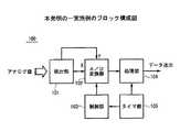
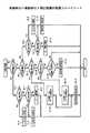
図5は本発明の一実施例のブロック構成図を示す。
【0031】
本実施例の加速度検出装置100は、検出部101、アナログ/ディジタル変換器102、制御部103、処理部104、タイマ部105から構成される。
【0032】
検出部101は、レバーのX方向の変移を検出する第1のホール素子及びレバーのY方向の変移を検出する第2のホール素子に接続され、第1及び第2のホール素子からの第1及び第2のアナログ検出信号を受信する。検出部101は、X方向の変移に応じた第1のアナログ信号及びY方向の変移に応じた第2のアナログ信号をA/D変換器102に供給する。
【0033】
A/D変換器102は、第1及び第2のアナログ信号をそれぞれ、第1及び第2のディジタルデータに変換する。A/D変換器102は、制御部103からのクロックに応じて変換タイミングが制御される。
【0034】
制御部103は、タイマ部105からのクロックに応じてA/D変換器102の変換タイミングを制御する。処理部104は、タイマ部105からのクロックに応じて後述するようにA/D変換器102からの第1及び第2のディジタルデータから加速方向を検出する。
【0035】
処理部104には、メモリが内蔵されている。メモリは、ROM、RAMから構成される。ROMには、A/D変換器102からのデータに基づいて加速度を検出するためのプログラムが記憶される。また、RAMは、プログラムを実行するときの作業用記憶領域として用いられる。
【0036】
タイマ部105は、所定のクロックを制御部103及び処理部104に供給する。
【0037】
次に、処理部104の波形認識処理について詳細に説明する。
【0038】
本実施例の処理部104は、X方向、Y方向の検出値の波形の変化に応じて加速度の加わった方向を認識する。
【0039】
例えば、力が加わった際に生じる検出値の波形と加わった力が停止したときに生じる検出値の波形とにより加速度を認識する。
【0040】
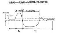
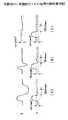
図6に本発明の一実施例の加速度検出値の波形図を示す。
【0041】
加速度検出値は、主に第1波W1、及び第2波W2から構成される。第1波W1は、加速度を加えたときに発生する波形である。第2波W2は、加速度が停止したときに発生する波形である。また、正常な状態で加速度が印加されると、第1波W1の期間T1と第2波w2を含む収束期間T2とは一定の関係となる。
【0042】
処理部104は、この波形の変化を複数の閾値を設けて検出し、加速度の認識を行なう。
【0043】
ここで、処理部104に設定される閾値について説明する。
【0044】
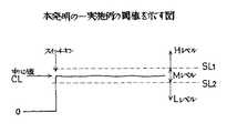
図7は本発明の一実施例の閾値を示す図を示す。
【0045】
処理部104には、第1、第2の閾値SL1、SL2が設定されている。第1の閾値SL1と第2の閾値SL2とは、中心値CLに上下対象に設定されている。なお、中心値CLは、電源などが投入されたときバイアスレベルである。第1の閾値SL1は、ハイレベルを検出する閾値である。第2の閾値SL2は、ローレベルを検出する閾値である。
【0046】
処理部104は、検出値が第1の閾値SL1より大きいと、ハイレベルであると判定し、第1の閾値SL1と第2の閾値SL2との間にあるとミディアムレベルであると判定し、第2の閾値SL2より小さいと、ローレベルであると判定し、その判定結果に基づいて加速度を認識する。
【0047】
処理部104の処理は、主に入力パターン一致処理、入力パターン修正処理、加速度測定処理から構成される。
【0048】
入力パターン一致処理は、入力パターンが加速度のパターンと一致するか否かを判定するための処理である。
【0049】
処理部104は、検出値を監視していて、X方向又はY方向の検出値のいずれかが第1又は第2の閾値SL1、SL2を超えたると入力パターン一致処理を開始する。このとき、X方向の検出値とY方向の検出値とが同タイミングで、検出されるとは限らないので、初期検出値がミディアムレベルの場合、一定時間内に波形に変化があれば、初期検出値をそのときのレベルに設定する。
【0050】
検出値が両方とも再び閾値ミディアムレベルとなることで、第1波W1が終了したと判定する。
【0051】
入力パターン修正処理は、ショート処理、キャンセル処理、ノイズ処理、反転処理から構成される。
【0052】
まず、ショート処理について詳細に説明する。
【0053】
ショート処理は、第1波W1の継続期間T1に応じて採用する方向を決定する処理である。
【0054】
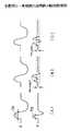
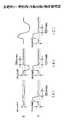
図8は本発明の一実施例の処理部の動作説明図を示す。
【0055】
図8(A)に示すようにX方向の第1波W1の期間T1がT11、Y方向の第1波W1の期間T1がT12である場合には、T11とT12との比に応じて採用するか否かを決定する。例えば、T12がT11の50%以下の場合には、Y方向の検出値は採用しないようにする。
【0056】
また、図8(B)に示すようにY方向の第1波W1が一度ハイレベルとなった後、ミディアムレベルとされ、再びハイレベルとされている場合には、2つのハイレベル期間を足した期間をハイレベル期間とし、波形の判定を行なう。
【0057】
さらに、図8(C)に示すようにY方向の第1波W1が一度ハイレベルとなった後、ローレベルとされ、再びハイレベルとされている場合には、2つのハイレベルの期間を連続した第1波とは認識しないようにする。
【0058】
次にキャンセル処理について説明する。
【0059】
キャンセル処理は、X方向のピーク値とY方向のピーク値との比に応じて検出値をキャンセルする処理である。
【0060】
図9に本発明の一実施例のキャンセル処理の動作説明図を示す。
【0061】
例えば、図9(A)に示すようにY方向の検出値VxがX方向の検出値Vyに比べて小さく場合には、Y方向の検出値をミディアムレベルとする。
【0062】
しかし、図9(B)に示すようにY方向の検出値VxがX方向の検出値Vyに比べて小さく場合でも、ショート処理の対象である場合には、X方向の検出値をミディアムレベルとする。
【0063】
次に、ノイズ処理につてい説明する。
ノイズ処理は、検出値をノイズとして検出する処理である。
【0064】
図10に本発明の一実施例のノイズ処理の動作説明図を示す。
【0065】
図10(A)に示すようにY方向の検出値において第1波W1が検出されてから一定時間、例えば、100ms経過しても第2波W2が発生しない場合には、Y方向の検出値の第1波W1をキャンセルし、ミディアムレベルとする。
【0066】
しかし、図10(B)に示すようにX方向の検出値がショート処理の対象となっている場合には、ショート処理を優先させ、Y方向の検出値を採用する。
【0067】
また、図10(C)に示すようにX方向の検出値が検出されな場合には、キャンセル処理は行なわないようにする。
【0068】
次に反転処理について説明する。
【0069】
反転処理は、第1波W1と第2波w2とを反転させて考える処理である。
【0070】
図11、図12は本発明の一実施例の反転処理の動作説明図を示す。
【0071】
図11(A)に示すようにY方向の検出値において第1波W1が来てから所定時間たっても第2波W2がこない場合に、Y方向の検出値の第1波w1を第2波W2として扱い、検出値の極性を反転させ、ローレベルとし、第1波W1はミディアムレベルとする。
【0072】
図11(B)に示すようにX方向の検出値も第1波W1がきてから所定時間たっても第2波W2がこない場合には、X方向の検出値も第1波W1を第2波W2として扱い、検出値の極性を反転させ、ハイレベルとし、第1波W1はミディアムレベルとする。
【0073】
図11(C)に示すようにX方向の検出値の波形が条件を満たしている場合には、Y方向の検出値に対して反転処理は行なわない。
【0074】
図12(A)に示すようにX方向の検出値がキャンセル処理の対象となっている場合には、Y方向の検出値を採用する。しかし、このとき、X方向の検出値から第1波W1を認識できるので、Y方向の検出値に対しては反転処理は行なわない。
【0075】
図12(B)に示すようにX方向の検出値がショート処理の対象となっている場合には、Y方向の検出値を採用する。しかし、X方向の検出値から第1波W1を認識できるので、Y方向の検出値に対しては反転処理は行なわない。
【0076】
次に、加速度測定処理について説明する。
【0077】
加速度測定処理は、加速度を測定するための処理である。
【0078】
加速度は、まず、第1波w1のピーク検出値Dpeekとパターン一致処理開始時からピーク検出値Dpeekに達するまでの時間Tpeekを測定し、例えば、(Dpeek/Tpeek)を加速度とする。なお、加速度は、ピーク検出値Dpeekと時間Tpeekとの関数から求めるようにしてもよい。
【0079】
次に、処理部12の処理の詳細について説明する。
【0080】
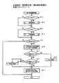
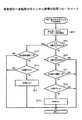
図13は本発明の一実施例の波形認識処理の処理フローチャートを示す。
【0081】
波形認識処理は、ステップS1−1〜S1−12の処理から構成される。
【0082】
ステップS1−1は、第1波形を確定済みか否かを判定するステップである。処理部104は、ステップS1−1で第1波形が確定済みでないと判定した場合には、次にステップS1−2を実行する。
【0083】
ステップS1−2は、第1波形の判定中か否かを判定するステップである。処理部104は、ステップS1−2で第1波形の判定中でないと判断した場合には、次にステップS1−3を実行する。
【0084】
ステップS1−3は、初期検出レベルを設定するステップである。ステップS1−3の処理については後で図面とともに詳細に説明する。
【0085】
また、処理部104がステップS1−2で第1波形を判定中であるの場合には、次にステップS1−4を実行する。ステップS1−4は、第1波形を確定するステップである。ステップS1−4の処理については後で図面とともに詳細に説明する。
【0086】
ステップS1−5は、ステップS1−4で第1波形が確定したか否かを判定するステップである。処理部1−4は、ステップS1−5で第1波形が確定したと判定した場合には、次にステップS1−6を実行する。ステップS1−6はキャンセル処理を行なうステップである。ステップS1−6のキャンセル処理については後で図面とともに詳細に説明する。
【0087】
また、処理部104は、ステップS1−1で第1波形が確定済みであると判定した場合には、ステップS1−7を実行する。ステップS1−7は、第2波形が確定済みか否かを判定するステップである。
【0088】
処理部104は、ステップS1−7で、第2波形が不確定であると判定した場合には、ステップS1−8を実行する。ステップS1−8は、第2波待機処理を行なうステップである。ステップS1−8の処理については後で図面とともに詳細に説明する。また、ステップS1−9は、パターン判定用フラグレジスタを初期化するステップである。
【0089】
ステップS1−7で、第2波形が確定済みであると判定された場合には、ステップS1−10が実行される。ステップS1−10は、電圧安定待ち受け処理を行なうステップである。ステップS1−10の処理については後で図面とともに詳細に説明する。
【0090】
ステップS1−11は、電圧が安定したか否かを判定するステップである。処理部104は、ステップS1−11で電圧が安定したと判定すると、ステップS1−12を実行する。ステップS1−12は、パターン設定処理を行なうステップである。ステップS1−12の処理については後で図面とともに詳細に説明する。
【0091】
処理部104が上記ステップS1−1〜S1−12を繰り返すことにより、加速度及びその方向が検出される。
【0092】
次に、ステップS1−3の初期検出レベル設定処理について詳細に説明する。
【0093】
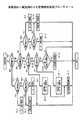
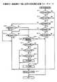
図14は本発明の一実施例の初期検出レベル設定処理の処理フローチャートを示す。
【0094】
初期検出レベル設定処理は、ステップS2−1〜S2−11のステップから構成される。ステップS2−1〜S2−5はX方向の初期検出レベルを設定する処理であり、ステップS2−6〜S2−11はY方向の初期検出レベルを設定する処理である。
【0095】
ステップS2−1は、X方向の検出値がハイレベルか否かを判定するステップである。処理部104は、ステップS2−1でX方向の検出値がハイレベルであると判定した場合には、ステップS2−2を実行する。ステップS2−2は、X方向の初期検出レベルをハイレベルに設定するステップである。
【0096】
処理部104は、ステップS2−1でX方向の検出値がハイレベルでないと判定した場合には、次にステップS2−3を実行する。ステップS2−3はX方向の検出値がローレベルか否かを判定するステップである。
【0097】
処理部104は、ステップS2−3でX方向の検出値がローレベルであると判定した場合には、ステップS2−4を実行する。ステップS2−4は、X方向の初期検出レベルをローレベルに設定するステップである。
【0098】
また、処理部104は、ステップS2−3でX方向の検出値がローレベルではないと判定した場合には、ステップS2−5を実行する。ステップS2−5は、X方向の初期検出レベルをミディアムレベルに設定するステップである。
【0099】
なお、処理部104は、X方向の検出値が第1の閾値より大きいときには、ハイレベルであると判定し、X方向の検出値が第2の閾値より小さいときには、ローレベルであると判定する。
【0100】
ステップS2−6は、Y方向の検出値がハイレベルか否かを判定するステップである。処理部104は、ステップS2−6でY方向の検出値がハイレベルであると判定した場合には、ステップS2−7を実行する。ステップS2−7は、Y方向の初期検出レベルをハイレベルに設定するステップである。
【0101】
処理部104は、ステップS2−6でY方向の検出値がハイレベルでないと判定した場合には、次にステップS2−8を実行する。ステップS2−8はY方向の検出値がローレベルか否かを判定するステップである。
【0102】
処理部104は、ステップS2−8でY方向の検出値がローレベルであると判定した場合には、ステップS2−9を実行する。ステップS2−9は、Y方向の初期検出レベルをローレベルに設定するステップである。
【0103】
また、処理部104は、ステップS2−8でX方向の検出値がローレベルではないと判定した場合には、ステップS2−10を実行する。ステップS2−10は、X方向の初期検出レベルをミディアムレベルに設定するステップである。
【0104】
なお、処理部104は、Y方向の検出値が第1の閾値より大きいときには、ハイレベルであると判定し、Y方向の検出値が第2の閾値より小さいときには、ローレベルであると判定する。
【0105】
以上により入力波形の初期検出レベルが判定される。
【0106】
次に、ステップS1−4の第1波形確定処理について詳細に説明する。
【0107】
図15は本発明の一実施例の第1波形確定処理の処理フローチャートを示す。
【0108】
第1波形確定処理は、ステップS3−1〜S3−11から構成される。
【0109】
ステップS3−1は、X方向の検出レベルの判定が終了したか否かを判定するステップである。処理部104はステップS3−1でX方向の検出レベルの判定が終了したと判定した場合には、ステップS3−2を実行する。ステップS3−2は、X判定処理を実行するステップである。ステップS3−2の処理については後で図面とともに詳細に説明する。
【0110】
処理部104はステップS3−1でX判定処理が終了したと判定すると、ステップS3−3を実行する。ステップS3−3は、Y方向の検出レベルの判定が終了したか否かを判定するステップである。処理部104はステップS3−3でY方向の検出レベルの判定が終了したと判定した場合には、ステップS3−4を実行する。ステップS3−4は、Y判定処理を実行するステップである。ステップS3−4の処理については後で図面とともに詳細に説明する。
【0111】
ステップS3−5は、ステップS3−2、S3−4の判定処理結果、X、Y方向の波形に変化があるか否かを判定するステップである。処理部104は、ステップS3−5でX,Y方向の波形に変化があると判定した場合には、ステップS3―6を実行する。ステップS3−6は、X、Y方向波形変化有を示す設定及びX、Y方向波形のチェック終了を示す設定を解除するステップである。
【0112】
ステップS3−7は、X方向の波形の観測時間をY方向の波形観測時間と比較し、X方向波形の観測時間がY方向波形の観測時間のa%以下か否かを判定するステップである。aは、予め設定された値であり、経験的に求められる。処理部104は、ステップS3−7でX方向波形の観測時間がY方向波形の観測時間のa%以下であると判定した場合には、ステップS3−8を実行する。ステップS3−8は、X方向の波形がY方向の波形に比べてショートである設定を行なうステップである。
【0113】
処理部104は、ステップS3−7でX方向波形の観測時間がY方向波形の観測時間のa%以下でないと判定した場合には、ステップS3−9を実行する。ステップS3−9は、Y方向の波形の観測時間をX方向の波形観測時間と比較し、Y方向波形の観測時間がX方向波形の観測時間のa%以下か否かを判定するステップである。
【0114】
処理部104は、ステップS3−9でY方向波形の観測時間がX方向波形の観測時間のa%以下であると判定した場合には、ステップS3−10を実行する。ステップS3−10は、Y方向の波形がX方向の波形に比べてショートである設定を行なうステップである。
【0115】
ステップS3−11は、初期波形確定を示す設定を行なうとともに、波形判定中を示す設定を解除するステップである。
【0116】
以上により、第1波形が確定する。
【0117】
次に、ステップS3−2のX判定処理について詳細に説明する。
【0118】
図16に本発明の一実施例のX判定処理の処理フローチャートを示す。
【0119】
X判定処理は、ステップS4−1〜S4−19から構成される。
【0120】
ステップS4−1は、X方向の初期検出値がハイレベルか否かを判定するステップである。処理部104は、ステップS4−1で初期検出値がハイレベルであると判定すると、ステップS4−2を実行する。ステップS4−2は、X方向の検出値がローレベルが否かを判定するステップである。
【0121】
処理部104は、ステップS4−2で検出値がローレベルであると判定した場合には、ステップS4−3、S4−4を実行する。ステップS4−3は、X方向の検出値のチェックが終了した旨の設定を行なうステップである。ステップS4−4は、X方向の検出値に変化がある旨の設定を行なうステップである。
【0122】
処理部104は、ステップS4−2で検出値がハイレベルであると判定した場合には、ステップS4−5を実行する。ステップS4−5は、X方向の検出値がミディアムレベルであるか否かを判定するステップである。
【0123】
処理部104は、ステップS4−5でX方向の検出値がミディアムレベルであると判定した場合には、ステップS4−4を実行する。また、処理部104は、ステップS4−5でX方向の検出値がミディアムレベルでないと判定した場合には、ステップS4−6を実行する。ステップS4−6は、その検出値をX方向のピーク値に更新するステップである。
【0124】
処理部104は、ステップS4−1で初期検出値がハイレベルではないと判定すると、ステップS4−7を実行する。ステップS4−7は、X方向の初期検出値がローレベルか否かを判定するステップである。
【0125】
処理部104は、ステップS4−7で初期検出値がローレベルであると判定すると、ステップS4−8を実行する。ステップS4−8は、X方向の検出値がハイレベルか否かを判定するステップである。
【0126】
処理部104は、ステップS4−8で検出値がハイレベルであると判定すると、ステップS4−9、S4−10を実行する。ステップS4−9は、X方向の検出値のチェックが終了した旨の設定を行なうステップである。ステップS4−9は、X方向の検出値に変化が有る旨の設定を行なうステップである。
【0127】
処理部104は、ステップS4−8で検出値がハイレベルではないと判定すると、ステップS4−11を実行する。ステップS4−11は、X方向の検出値がミディアムレベルか否かを判定する。
【0128】
処理部104は、ステップS4−11で検出値がミディアムレベルであると判定した場合には、ステップS4−10を実行する。また、処理部104は、ステップS4−11で検出値がミディアムレベルでないと判定したときには、ステップS4−12を実行する。ステップS4−12は、検出値をX方向のピーク値として更新するステップである。
【0129】
処理部104は、ステップS4−7で初期検出値がローレベルではないと判定した場合には、ステップS4−13を実行する。ステップS4−13は、検出値がハイレベルか否かを判定するステップである。
【0130】
処理部104は、ステップS4−13で検出値がハイレベルであると判定した場合には、ステップS4−14、S4−15を実行する。ステップS4−14は、X方向の初期検出値をハイレベルに設定するステップである。ステップS4−15は、検出値の測定時間を初期化するステップである。
【0131】
処理部104は、ステップS4−13で検出値がハイレベルではないと判定した場合には、ステップS4−16を実行する。ステップS4−16は、X方向の検出値がローレベルか否かを判定するステップである。
【0132】
処理部104は、ステップS4−16で検出値がローレベルであると判定すると、ステップS4−17、S4−15を実行する。ステップS4−17は、X方向の初期検出値をローレベルに設定するステップである。
【0133】
また、処理部104は、ステップS4−16で検出値がローレベルではないと判定した場合には、ステップS4−18を実行する。ステップS4−18は、X方向の検出値がミディアムレベルである状態がb時間以上か否かを判定するステップである。bは、予め設定された時間であり、入力機構の特性などに基づいて経験的に求められる。
【0134】
処理部104は、ステップS4−18でミディアムレベル状態がb時間以上継続したと判定した場合には、ステップS4−19が実行される。ステップS4−19は、X方向の検出値に波形変化がある旨の設定を行なうステップである。また、処理部104は、ステップS4−18でミディアムレベル状態がb時間以上継続していないと判定した場合には、そのまま処理を停止する。
【0135】
以上により、X方向の検出値の状態が判定される。
【0136】
次にステップS3−4のY判定処理について詳細に説明する。
【0137】
図17に本発明の一実施例のY判定処理の処理フローチャートを示す。
【0138】
Y判定処理は、ステップS5−1〜S5−19から構成される。
【0139】
ステップS5−1は、Y方向の初期検出値がハイレベルか否かを判定するステップである。処理部104は、ステップS5−1で初期検出値がハイレベルであると判定すると、ステップS5−2を実行する。ステップS5−2は、Y方向の検出値がローレベルが否かを判定するステップである。
【0140】
処理部104は、ステップS5−2で検出値がローレベルであると判定した場合には、ステップS5−3、S5−4を実行する。ステップS5−3は、Y方向の検出値のチェックが終了した旨の設定を行なうステップである。ステップS5−4は、Y方向の検出値に変化がある旨の設定を行なうステップである。
【0141】
処理部104は、ステップS5−2で検出値がハイレベルであると判定した場合には、ステップS5−5を実行する。ステップS5−5は、Y方向の検出値がミディアムレベルであるか否かを判定するステップである。
【0142】
処理部104は、ステップS5−5でY方向の検出値がミディアムレベルであると判定した場合には、ステップS5−4を実行する。また、処理部104は、ステップS5−5でY方向の検出値がミディアムレベルでないと判定した場合には、ステップS5−6を実行する。ステップS5−6は、その検出値をY方向のピーク値に更新するステップである。
【0143】
処理部104は、ステップS5−1で初期検出値がハイレベルではないと判定すると、ステップS5−7を実行する。ステップS5−7は、Y方向の初期検出値がローレベルか否かを判定するステップである。
【0144】
処理部104は、ステップS5−7で初期検出値がローレベルであると判定すると、ステップS5−8を実行する。ステップS5−8は、Y方向の検出値がハイレベルか否かを判定するステップである。
【0145】
処理部104は、ステップS5−8で検出値がハイレベルであると判定すると、ステップS5−9、S5−10を実行する。ステップS5−9は、Y方向の検出値のチェックが終了した旨の設定を行なうステップである。ステップS5−9は、Y方向の検出値に変化が有る旨の設定を行なうステップである。
【0146】
処理部104は、ステップS5−8で検出値がハイレベルではないと判定すると、ステップS5−11を実行する。ステップS5−11は、Y方向の検出値がミディアムレベルか否かを判定する。
【0147】
処理部104は、ステップS5−11で検出値がミディアムレベルであると判定した場合には、ステップS5−10を実行する。また、処理部104は、ステップS5−11で検出値がミディアムレベルでないと判定したときには、ステップS5−12を実行する。ステップS5−12は、検出値をY方向のピーク値として更新するステップである。
【0148】
処理部104は、ステップS5−7で初期検出値がローレベルではないと判定した場合には、ステップS5−13を実行する。ステップS5−13は、検出値がハイレベルか否かを判定するステップである。
【0149】
処理部104は、ステップS5−13で検出値がハイレベルであると判定した場合には、ステップS5−14、S5−15を実行する。ステップS5−14は、Y方向の初期検出値をハイレベルに設定するステップである。ステップS5−15は、検出値の測定時間を初期化するステップである。
【0150】
処理部104は、ステップS5−13で検出値がハイレベルではないと判定した場合には、ステップS5−16を実行する。ステップS5−16は、Y方向の検出値がローレベルか否かを判定するステップである。
【0151】
処理部104は、ステップS5−16で検出値がローレベルであると判定すると、ステップS5−17、S5−15を実行する。ステップS5−17は、Y方向の初期検出値をローレベルに設定するステップである。
【0152】
また、処理部104は、ステップS5−16で検出値がローレベルではないと判定した場合には、ステップS5−18を実行する。ステップS5−18は、Y方向の検出値がミディアムレベルである状態がb時間以上か否かを判定するステップである。bは、予め設定された時間であり、入力機構の特性などに基づいて経験的に求められる。
【0153】
処理部104は、ステップS5−18でミディアムレベル状態がb時間以上継続したと判定した場合には、ステップS5−19が実行される。ステップS5−19は、Y方向の検出値に波形変化がある旨の設定を行なうステップである。また、処理部104は、ステップS5−18でミディアムレベル状態がb時間以上継続していないと判定した場合には、そのまま処理を停止する。
【0154】
以上により、Y方向の検出値の状態が判定される。
【0155】
次に、ステップS1−6のキャンセル処理について詳細に説明する。
【0156】
図18に本発明の一実施例のキャンセル処理の処理フローチャートを示す。
【0157】
キャンセル処理は、ステップS6−1〜S6−9から構成される。
【0158】
ステップS6−1は、X方向、Y方向のピーク値を導入するステップである。なお、ピーク値は、中心値からの大きさで表される。ステップS6−2は、X方向のピーク値とY方向のピーク値とを比較し、X方向のピーク値がY方向のピーク値のc%以下か否かを判定するステップである。cは、処理部104に予め設定された値であり、経験的に求められる。
【0159】
処理部104は、ステップS6−2でX方向のピーク値がY方向のピーク値のc%以下であると判定した場合には、次にステップS6−3を実行する。ステップS6−3は、Y方向の初期検出値がミディアムレベルか否かを判定するステップである。
【0160】
処理部104は、ステップS6−3でY方向の初期検出値がミディアムレベルであると判定した場合には、そのまま処理を終了する。また、処理部104は、ステップS6−3でY方向の初期検出値がミディアムレベルではないと判定した場合には、ステップS6−4を実行する。ステップS6−4は、Y方向検出値がショートである旨を示す設定があるか否かを判定するステップである。なお、Y方向検出値がショートである旨の設定は、ステップS3−10で行なわれる。
【0161】
処理部104は、ステップS6−4でYショートが設定されているときには、そのまま処理を終了する。また、処理部104は、ステップS6−4でYショートが設定されているときには、ステップS6−5を実行する。ステップS6−5は、X方向検出をキャンセルするXCANSLをセットするステップである。
【0162】
処理部104は、ステップS6−2で、X方向のピーク値がY方向のピーク値のc%以下ではないと判定した場合には、次にステップS6−6を実行する。ステップS6−6は、X方向のピーク値とY方向のピーク値とを比較し、Y方向のピーク値がX方向のピーク値のc%以下か否かを判定するステップである。
【0163】
処理部104は、ステップS6−6でY方向のピーク値がX方向のピーク値のc%以下であると判定した場合には、そのまま処理を終了する。また、処理部104は、ステップS6−6でY方向のピーク値がX方向のピーク値のc%以下でないと判定した場合には、ステップS6−7を実行する。ステップS6−7は、X方向の初期検出値がミディアムレベルか否かを判定するステップである。
【0164】
処理部104は、ステップS6−7でX方向の初期検出値がミディアムレベルであると判定した場合には、そのまま処理を終了する。また、処理部104は、ステップS6−7でX方向の初期検出値がミディアムレベルではないと判定した場合には、ステップS6−8を実行する。ステップS6−8は、X方向検出値がショートである旨を示す設定があるか否かを判定するステップである。なお、X方向検出値がショートである旨の設定は、ステップS3−8で行なわれる。
【0165】
処理部104は、ステップS6−8でXショートが設定されていると判定したときには、そのまま処理を終了する。また、処理部104は、ステップS6−8でXショートが設定されているときには、ステップS6−9を実行する。ステップS6−9は、Y方向検出をキャンセルするYCANSLをセットするステップである。
【0166】
以上により、X又はY方向検出をキャンセルすることを示すXCANSL、YCANSLがセットされる。
【0167】
次にステップS1−8の第2波待ち処理について詳細に説明する。
【0168】
図19に本発明の一実施例の第2波待ち処理の処理フローチャートを示す。
【0169】
第2波待ち処理は、ステップS7−1〜S7−7から構成される。
【0170】
ステップS7−1は、X方向の検出値に第2変化があるか否かを判定するステップである。処理部104は、ステップS7−1でX方向の検出値に第2変化があると判定した場合、そのままステップS7−3を実行する。また、処理部104は、ステップS7−1でX方向の検出値に第2変化がないと判定した場合には、ステップS7−2を実行した後、ステップS7−3を実行する。
【0171】
ステップS7−2は、X方向の検出値から第2波形を判定するX第2波形判定処理を行なうステップである。ステップS7−2のX第2波形判定処理については後で図面とともに詳細に説明する。
【0172】
ステップS7−3は、Y方向の検出値に第2変化があるか否かを判定するステップである。処理部104は、ステップS7−3でY方向の検出値に第2変化があると判定した場合、そのままステップS7−5を実行する。また、処理部104は、ステップS7−3でX方向の検出値に第2変化がないと判定した場合には、ステップS7−4を実行した後、ステップS7−5を実行する。ステップS7−4は、Y方向の検出値から第2波形を判定するY第2波形判定処理を行なうステップである。ステップS7−4のY第2波形判定処理については後で図面とともに詳細に説明する。
【0173】
ステップS7−5は、X、Y方向検出値の波形の変化を示す設定がされているか否かを判定するステップである。なお、X方向検出値の波形の変化を示す設定は、ステップS4−4、S4−10、S4−19で行なわれ、Y方向検出値の波形変化を示す設定は、ステップS5−4、S5−10、S5−19で行なわれる。
【0174】
処理部104は、ステップS7−5でX,Y方向検出値の波形の変化を示す設定がされていないと判断した場合には、そのまま処理を終了する。また、処理部104は、ステップS7−5でX,Y方向検出値の波形の変化を示す設定がされていると判断した場合には、ステップS7−6、S7−7順次に実行する。ステップS7−6は、第2波形であると確定された旨を設定するステップである。また、ステップS7−7は、波形変化がある旨の設定を解除するステップである。
【0175】
ステップS7−8は、X方向の検出値がノイズである旨の設定が行なわれているか否かを判定するステップである。処理部104は、ステップS7−8でX方向の検出値がノイズである旨の設定が行なわれていない場合には、そのまま処理を実行し、X方向の検出値がノイズである旨の設定が行なわれていると判定された場合には、ステップS7−9を実行する。
【0176】
ステップS7−9は、Y方向の検出値がノイズである旨の設定が行なわれているか否かを判定するステップである。処理部104は、ステップS7−9でX方向の検出値がノイズである旨の設定が行なわれていない場合には、そのまま処理を実行し、Y方向の検出値がノイズである旨の設定が行なわれていると判定された場合には、ステップS7−10、ステップS7−11を実行する。
【0177】
ステップS7−10は、ノイズである旨の設定を解除するステップである。また、ステップS7−11は、X方向、Y方向の検出値が反転するのを待機する設定を行なうステップである。
【0178】
次に、ステップS7−2のX第2波形判定処理について詳細に説明する。
【0179】
図20は本発明の一実施例のX第2波形判定処理の処理フローチャートを示す。
【0180】
X第2波形判定処理は、ステップS8−1〜S8−14から構成されている。
【0181】
ステップS8−1は、XCANSLが設定されているか否かを判定するステップである。処理部104は、ステップS8−1でXCANSLが設定されていると判定した場合には、ステップS8−2を実行して、X第2波形判定処理を終了する。ステップS8−2は、X方向の検出値に第2波形の変化がある旨の設定を行なうステップである。
【0182】
処理部104は、ステップS8−1でXCANSLが設定されていないと判定した場合には、ステップS8−3を実行する。ステップS8−3は、XSHORTの設定があるか否かを判定するステップである。
【0183】
処理部104は、ステップS8−3でXSHORTが設定されていると判定した場合には、ステップS8−2を実行して処理を終了する。また、処理部104は、ステップS8−3でXSHORTが設定されていないと判定した場合には、ステップS8−4を実行する。ステップS8−4は、X方向の初期検出値がハイレベルであるか否かを判定するステップである。
【0184】
処理部104は、ステップS8−4でX方向の初期検出値がハイレベルであると判定した場合には、ステップS8−5が実行される。ステップS8−5は、検出値がローレベルか否かを判定するステップである。
【0185】
処理部104は、ステップS8−5で検出値がローレベルであると判定した場合には、ステップS8−2を実行して処理を終了する。また、処理部104は、ステップS8−5で検出値がローレベルではないと判定した場合には、ステップS8−6が実行する。ステップS8−6は、第1波の検出を終了してからd時間経過したか否かを判定するステップである。ここで、dは処理部104に予め設定された所定の値であり、経験的に求められる。
【0186】
処理部104は、ステップS8−6で第1波の検出が終了してからd時間経過していないと判定した場合には、そのまま処理を終了し、ステップS8−6で第1波の検出が終了してからd時間経過したと判定した場合には、ステップS8−7を実行する。ステップS8−7は、Y方向の初期検出値がミディアムレベルであるか否かを判定するステップである。
【0187】
処理部104は、ステップS8−7でY方向の初期検出値がミディアムレベルであると判定した場合には、ステップS8−8、S8−2を実行して処理を終了する。ステップS8−8は、X方向の検出値が判定する状態を設定するステップである。また、処理部104は、ステップS8−7でY方向の初期検出値がミディアムレベルではないと判定した場合には、ステップS8−9を実行する。ステップS8−9は、YSHORTが設定されているか否かを判定するステップである。
【0188】
処理部104は、ステップS8−9でYSHORTが設定されていると判定した場合には、ステップS8−2を実行して処理を終了する。また、処理部104は、ステップS8−9でYSHORTが設定されていないと判定した場合には、ステップS8−10を実行する。ステップS8−10は、YCANSLが設定されているか否かを判定するステップである。
【0189】
処理部104は、ステップS8−10でYCANSLが設定されていると判定した場合には、ステップS8−2を実行して処理を終了する。また、処理部104は、ステップS8−10でYCANSLが設定されていないと判定した場合には、ステップS8−11、S8−2を実行して処理を終了する。ステップS8−1は、X方向の検出値がノイズである旨の設定するステップである。
【0190】
また、処理部104は、ステップS8−4でX方向の初期検出値がハイレベルではないと判定した場合には、ステップS8−12を実行する。ステップS8−12は、X方向の初期検出値がローレベルであるか否かを判定するステップである。
【0191】
処理部104は、ステップS8−12でX方向の初期検出値がローレベルであると判定した場合には、ステップS8−13を実行する。ステップS8−13は、X方向の検出値がハイレベルか否かを判定するステップである。
【0192】
処理部104は、ステップS8−13で検出値がハイレベルであると判定した場合には、ステップS8−2を実行して処理を終了する。また、処理部104は、ステップS8−13で検出値がハイレベルではないと判定した場合には、ステップS8−6を実行する。
【0193】
また、処理部104は、ステップS8−12でX方向の初期検出値がローレベルではないと判定した場合には、ステップS8−14を実行する。ステップS8−14は、X方向の初期検出値がミディアムレベルであるか否かを判定するステップである。
【0194】
処理部104は、ステップS8−14でX方向の初期検出値がミディアムレベルであると判定した場合には、そのまま処理を終了する。また、処理部104は、ステップS8−14でX方向の初期検出値がミディアムレベルではないと判定した場合には、ステップS8−2を実行して処理を終了する。
【0195】
以上がX第2波形判定処理である。
【0196】
次にステップS7−4のY第2波形判定処理について図面とともに詳細に説明する。
【0197】
図21は本発明の一実施例のY第2波形判定処理の処理フローチャートを示す。
【0198】
Y第2波形判定処理は、ステップS9−1〜S9−14から構成されている。
【0199】
ステップS9−1は、YCANSLが設定されているか否かを判定するステップである。処理部104は、ステップS9−1でYCANSLが設定されていると判定した場合には、ステップS9−2を実行して、Y第2波形判定処理を終了する。ステップS9−2は、Y方向の検出値に第2波形の変化がある旨の設定を行なうステップである。
【0200】
処理部104は、ステップS9−1でYCANSLが設定されていないと判定した場合には、ステップS9−3を実行する。ステップS9−3は、YSHORTの設定があるか否かを判定するステップである。
【0201】
処理部104は、ステップS9−3でYSHORTが設定されていると判定した場合には、ステップS9−2を実行して処理を終了する。また、処理部104は、ステップS9−3でYSHORTが設定されていないと判定した場合には、ステップS9−4を実行する。ステップS9−4は、Y方向の初期検出値がハイレベルであるか否かを判定するステップである。
【0202】
処理部104は、ステップS9−4でY方向の初期検出値がハイレベルであると判定した場合には、ステップS9−5が実行される。ステップS9−5は、検出値がローレベルか否かを判定するステップである。
【0203】
処理部104は、ステップS9−5で検出値がローレベルであると判定した場合には、ステップS9−2を実行して処理を終了する。また、処理部104は、ステップS9−5で検出値がローレベルではないと判定した場合には、ステップS9−6が実行する。ステップS9−6は、第1波の検出を終了してからd時間経過したか否かを判定するステップである。ここで、dは処理部104に予め設定された所定の値であり、経験的に求められる。
【0204】
処理部104は、ステップS9−6で第1波の検出が終了してからd時間経過していないと判定した場合には、そのまま処理を終了し、ステップS9−6で第1波の検出が終了してからd時間経過したと判定した場合には、ステップS9−7を実行する。ステップS9−7は、Y方向の初期検出値がミディアムレベルであるか否かを判定するステップである。
【0205】
処理部104は、ステップS9−7でY方向の初期検出値がミディアムレベルであると判定した場合には、ステップS9−8、S9−2を実行して処理を終了する。ステップS9−8は、Y方向の検出値が反転する状態を設定するステップである。また、処理部104は、ステップS9−7でX方向の初期検出値がミディアムレベルではないと判定した場合には、ステップS9−9を実行する。ステップS9−9は、XSHORTが設定されているか否かを判定するステップである。
【0206】
処理部104は、ステップS9−9でXSHORTが設定されていると判定した場合には、ステップS9−2を実行して処理を終了する。また、処理部104は、ステップS9−9でXSHORTが設定されていないと判定した場合には、ステップS9−10を実行する。ステップS9−10は、XCANSLが設定されているか否かを判定するステップである。
【0207】
処理部104は、ステップS9−10でXCANSLが設定されていると判定した場合には、ステップS9−2を実行して処理を終了する。また、処理部104は、ステップS9−10でXCANSLが設定されていないと判定した場合には、ステップS9−11、S9−2を実行して処理を終了する。ステップS9−11は、Y方向の検出値がノイズである旨の設定するステップである。
【0208】
また、処理部104は、ステップS9−4でY方向の初期検出値がハイレベルではないと判定した場合には、ステップS9−12を実行する。ステップS9−12は、Y方向の初期検出値がローレベルであるか否かを判定するステップである。
【0209】
処理部104は、ステップS9−12でY方向の初期検出値がローレベルであると判定した場合には、ステップS9−13を実行する。ステップS9−13は、Y方向の検出値がハイレベルか否かを判定するステップである。
【0210】
処理部104は、ステップS9−13で検出値がハイレベルであると判定した場合には、ステップS9−2を実行して処理を終了する。また、処理部104は、ステップS9−13で検出値がハイレベルではないと判定した場合には、ステップS9−6を実行する。
【0211】
また、処理部104は、ステップS9−12でY方向の初期検出値がローレベルではないと判定した場合には、ステップS9−14を実行する。ステップS9−14は、Y方向の初期検出値がミディアムレベルであるか否かを判定するステップである。
【0212】
処理部104は、ステップS9−14でY方向の初期検出値がミディアムレベルであると判定した場合には、そのまま処理を終了する。また、処理部104は、ステップS9−14でY方向の初期検出値がミディアムレベルではないと判定した場合には、ステップS9−2を実行して処理を終了する。
【0213】
以上がY第2波形判定処理である。
【0214】
以上本実施例によれば、使用者が意図する加速度を正確に検出することができる。
【0215】
なお、本実施例では、入力装置で上記プログラムを実行したが、ゲーム機で上記プログラムを実行するようにしてもよい。このとき、ゲームソフトを提供するためのCD−ROM、DVD−ROMなどの記録媒体からゲーム機内のメモリにインストールして実行したり、記録媒体から実行するようにしてもよい。また、ネットワークを介してゲーム機のメモリにダウンロードして用いるようにしてもよい。
【0216】
また、本発明は、上記実施例に限定されるものではなく、本発明の範囲から逸脱することなく種々の変形例がなされるものである。
【0217】
【発明の効果】
上述の如く、本発明によれば、加速度を検出する機構の特性に合った波形の信号だけを加速度と判定して、加速度を検出するので、不要な加速度成分を検出することがない等の特長を有する。
【0218】
本発明によれば、レベルが一定値以上の波形の信号が得られる加速度を有効にするので、振動などによる微小な加速度を検出することがない等の特長を有する。
【0219】
本発明によれば、波形が所定レベル以上となる期間となる波形を加速度と判定するので、微小な振動を加速度として検出することがなく、よって、不要な加速度成分を検出することがない等の特長を有する。
【0220】
本発明によれば、第1波がきてから所定時間たっても第2波がこない場合には、第1波を第2波として扱い、検出信号の極性を反転させ、ロー又はハイレベルとし、第1波はミディアムレベルとし、加速度を判定することにより、正規の波形でない場合にも加速度を検出できる等の特長を有する。
【図面の簡単な説明】
【図1】ゲーム装置における入力方法の一例を説明するための図である。
【図2】従来の入力装置の一例の構成図である。
【図3】従来の加速度センサの一例の分解斜視図である。
【図4】従来の加速度センサの一例の動作説明図である。
【図5】本発明の一実施例のブロック構成図である。
【図6】本発明の一実施例の加速度検出値の波形図である。
【図7】本発明の一実施例の閾値を示す図である。
【図8】本発明の一実施例の処理部の動作説明図である。
【図9】本発明の一実施例のキャンセル処理の動作説明図である。
【図10】本発明の一実施例のノイズ処理の動作説明図である。
【図11】本発明の一実施例の反転処理の動作説明図である。
【図12】本発明の一実施例の反転処理の動作説明図である。
【図13】本発明の一実施例の波形認識処理の処理フローチャートである。
【図14】本発明の一実施例の初期検出レベル設定処理の処理フローチャートである。
【図15】本発明の一実施例の第1波形確定処理の処理フローチャートである。
【図16】本発明の一実施例のX判定処理の処理フローチャートである。
【図17】本発明の一実施例のY判定処理の処理フローチャートである。
【図18】本発明の一実施例のキャンセル処理の処理フローチャートである。
【図19】本発明の一実施例の第2波待ち処理の処理フローチャートである。
【図20】本発明の一実施例のX第2波形判定処理の処理フローチャートである。
【図21】本発明の一実施例のY第2波形判定処理の処理フローチャートである。
【符号の説明】
100 加速度検出装置
101 検出部
102 A/D変換器
103 制御部
104 処理部
105 タイマ部[0001]
BACKGROUND OF THE INVENTION
The present invention relates to an acceleration detection circuit, an acceleration detection method, an input device, and a recording medium, and more particularly to an acceleration detection circuit, an acceleration detection method, an input device, and a recording medium that detect acceleration according to an input signal from a sensor.
[0002]
In recent years, in the field of game devices, various ideas have been proposed, and various input methods are required accordingly. As one of such input methods, an input device for detecting limb movements is required. As a method of detecting the movement of the limbs, a method of detecting acceleration can be considered. As a sensor for detecting acceleration, there is a sensor using a weight and a spring. In such a sensor, vibration due to the elasticity of the spring is generated, so that an unnecessary component signal is likely to be generated.
[0003]
[Prior art]
FIG. 1 is a diagram for explaining an example of an input method in a game device.
[0004]
The game shown in FIG. 1 includes an
[0005]
When the
[0006]
FIG. 2 is a block diagram showing an example of a conventional input device.
[0007]
The
[0008]
The apparatus
[0009]
The printed
[0010]
FIG. 3 shows an exploded perspective view of an example of a conventional acceleration sensor.
[0011]
The
[0012]
The
[0013]
The
[0014]
The
[0015]
FIG. 4 shows an operation explanatory diagram of an example of a conventional acceleration sensor. FIG. 4A shows a state when acceleration is not working, and FIG. 4B shows a state when acceleration works.
[0016]
When the acceleration is not applied, the
[0017]
When acceleration is generated in the
[0018]
Details of these mechanisms are described in Japanese Patent Application No. 10-99517 filed earlier by the present applicant.
[0019]
The
[0020]
[Problems to be solved by the invention]
However, since the conventional acceleration detecting device simply detects the signal from the acceleration sensor as the acceleration, there is a problem that an unnecessary motion component is detected as noise.
[0021]
The present invention has been made in view of the above points, and an object thereof is to provide an acceleration detection circuit, an acceleration detection method, an input device, and a recording medium that can accurately extract a required acceleration component.
[0022]
[Means for Solving the Problems]
The present invention provides an acceleration detection circuit that detects acceleration from a detection signal corresponding to acceleration applied in a predetermined direction, waveform detection means for detecting a waveform of the detection signal, and acceleration based on the waveform detected by the waveform detection means. Acceleration determining means for determining whether the signal is valid or invalid, and the waveform of the detection signal is symmetrical with respect to the first wave and the first wave after the first wave with a center level as a center. A second wave that is generated, and the acceleration determining meansEven after a certain period of time If the second wave does not come, the first wave is changed to the second wave, The polarity of the detection signal is inverted and set to low or high level, the first wave is set to medium level, and the acceleration is determined .
[0029]
According to the present invention, acceleration can be made effective even when the waveform is not regular.
[0030]
DETAILED DESCRIPTION OF THE INVENTION
FIG. 5 shows a block diagram of an embodiment of the present invention.
[0031]
The
[0032]
The
[0033]
The A /
[0034]
The
[0035]
The
[0036]
The timer unit 105 supplies a predetermined clock to the
[0037]
Next, the waveform recognition process of the
[0038]
The
[0039]
For example, the acceleration is recognized based on a waveform of a detection value generated when a force is applied and a waveform of a detection value generated when the applied force is stopped.
[0040]
FIG. 6 shows a waveform diagram of acceleration detection values according to an embodiment of the present invention.
[0041]
The detected acceleration value mainly includes a first wave W1 and a second wave W2. The first wave W1 is a waveform generated when acceleration is applied. The second wave W2 is a waveform generated when the acceleration stops. When acceleration is applied in a normal state, the period T1 of the first wave W1 and the convergence period T2 including the second wave w2 have a certain relationship.
[0042]
The
[0043]
Here, the threshold value set in the
[0044]
FIG. 7 is a diagram showing threshold values according to an embodiment of the present invention.
[0045]
The
[0046]
When the detected value is larger than the first threshold SL1, the
[0047]
The processing of the
[0048]
The input pattern matching process is a process for determining whether or not the input pattern matches the acceleration pattern.
[0049]
The
[0050]
It is determined that the first wave W1 has ended when both of the detection values are again at the threshold medium level.
[0051]
The input pattern correction process includes a short process, a cancel process, a noise process, and an inversion process.
[0052]
First, the short process will be described in detail.
[0053]
The short process is a process of determining a direction to be adopted according to the duration T1 of the first wave W1.
[0054]
FIG. 8 is a diagram for explaining the operation of the processing unit according to the embodiment of the present invention.
[0055]
As shown in FIG. 8A, when the period T1 of the first wave W1 in the X direction is T11 and the period T1 of the first wave W1 in the Y direction is T12, it is adopted according to the ratio of T11 and T12. Decide whether or not to do. For example, when T12 is 50% or less of T11, the detection value in the Y direction is not adopted.
[0056]
In addition, as shown in FIG. 8B, when the first wave W1 in the Y direction once becomes a high level and then becomes a medium level and is again set to a high level, two high level periods are added. The determined period is set as a high level period, and the waveform is determined.
[0057]
Further, as shown in FIG. 8C, when the first wave W1 in the Y direction once becomes a high level and then becomes a low level and is again set to a high level, two high-level periods are divided. The first continuous wave is not recognized.
[0058]
Next, the cancellation process will be described.
[0059]
The cancel process is a process for canceling the detection value in accordance with the ratio between the peak value in the X direction and the peak value in the Y direction.
[0060]
FIG. 9 is a diagram for explaining the operation of the cancel process according to the embodiment of the present invention.
[0061]
For example, as shown in FIG. 9A, when the detected value Vx in the Y direction is smaller than the detected value Vy in the X direction, the detected value in the Y direction is set to the medium level.
[0062]
However, as shown in FIG. 9B, even if the detected value Vx in the Y direction is smaller than the detected value Vy in the X direction, the detected value in the X direction is set to the medium level if it is subject to short processing. To do.
[0063]
Next, noise processing will be described.
The noise process is a process for detecting a detected value as noise.
[0064]
FIG. 10 is a diagram for explaining the operation of noise processing according to an embodiment of the present invention.
[0065]
As shown in FIG. 10 (A), when the second wave W2 does not occur even after a lapse of a certain time, for example, 100 ms after the first wave W1 is detected in the detected value in the Y direction, the detected value in the Y direction. Cancel the first wave W1 to the medium level.
[0066]
However, when the detected value in the X direction is the target of the short process as shown in FIG. 10B, priority is given to the short process and the detected value in the Y direction is adopted.
[0067]
Also, as shown in FIG. 10C, when the detected value in the X direction is not detected, the cancel process is not performed.
[0068]
Next, the inversion process will be described.
[0069]
The inversion process is a process in which the first wave W1 and the second wave w2 are inverted.
[0070]
11 and 12 are diagrams for explaining the operation of the inversion process according to the embodiment of the present invention.
[0071]
As shown in FIG. 11A, when the second wave W2 does not come even after a predetermined time from the first wave W1 in the detected value in the Y direction, the first wave w1 of the detected value in the Y direction is changed to the second wave. Treat as W2, invert the polarity of the detection value to low level, and set the first wave W1 to medium level.
[0072]
As shown in FIG. 11B, when the detected value in the X direction also does not come in the second wave W2 even after a predetermined time from the arrival of the first wave W1, the detected value in the X direction also changes the first wave W1 to the second wave. Treat as W2, reverse the polarity of the detection value to high level, and set the first wave W1 to medium level.
[0073]
As shown in FIG. 11C, when the waveform of the detected value in the X direction satisfies the condition, the inversion process is not performed on the detected value in the Y direction.
[0074]
As shown in FIG. 12A, when the detected value in the X direction is the target of the cancellation process, the detected value in the Y direction is adopted. However, at this time, since the first wave W1 can be recognized from the detected value in the X direction, the inversion process is not performed on the detected value in the Y direction.
[0075]
As shown in FIG. 12B, when the detected value in the X direction is the target of the short process, the detected value in the Y direction is adopted. However, since the first wave W1 can be recognized from the detected value in the X direction, the inversion process is not performed on the detected value in the Y direction.
[0076]
Next, the acceleration measurement process will be described.
[0077]
The acceleration measurement process is a process for measuring acceleration.
[0078]
For the acceleration, first, the peak detection value Dpeek of the first wave w1 and the time Tpeek from the start of the pattern matching process to the peak detection value Dpeek are measured. For example, (Dpeek / Tpeek) is set as the acceleration. The acceleration may be obtained from a function of the peak detection value Dpeek and the time Tpeek.
[0079]
Next, details of the processing of the
[0080]
FIG. 13 shows a flowchart of the waveform recognition process according to an embodiment of the present invention.
[0081]
The waveform recognition process includes the processes of steps S1-1 to S1-12.
[0082]
Step S1-1 is a step of determining whether or not the first waveform has been confirmed. If the
[0083]
Step S1-2 is a step of determining whether or not the first waveform is being determined. If the
[0084]
Step S1-3 is a step of setting an initial detection level. The process of step S1-3 will be described later in detail with reference to the drawings.
[0085]
If the
[0086]
Step S1-5 is a step of determining whether or not the first waveform is confirmed in step S1-4. If the processing unit 1-4 determines that the first waveform has been determined in step S1-5, it next executes step S1-6. Step S1-6 is a step for performing cancellation processing. The cancellation process in step S1-6 will be described in detail later with reference to the drawings.
[0087]
If the
[0088]
If the
[0089]
If it is determined in step S1-7 that the second waveform has been confirmed, step S1-10 is executed. Step S1-10 is a step of performing voltage stabilization standby processing. The process of step S1-10 will be described later in detail with reference to the drawings.
[0090]
Step S1-11 is a step of determining whether or not the voltage is stable. When determining that the voltage is stabilized in step S1-11, the
[0091]
As the
[0092]
Next, the initial detection level setting process in step S1-3 will be described in detail.
[0093]
FIG. 14 is a flowchart showing the initial detection level setting process according to the embodiment of the present invention.
[0094]
The initial detection level setting process includes steps S2-1 to S2-11. Steps S2-1 to S2-5 are processes for setting the initial detection level in the X direction, and steps S2-6 to S2-11 are processes for setting the initial detection level in the Y direction.
[0095]
Step S2-1 is a step of determining whether or not the detected value in the X direction is at a high level. If the
[0096]
If the
[0097]
If the
[0098]
If the
[0099]
The
[0100]
Step S2-6 is a step of determining whether or not the detected value in the Y direction is at a high level. If the
[0101]
If the
[0102]
If the
[0103]
If the
[0104]
Note that the
[0105]
Thus, the initial detection level of the input waveform is determined.
[0106]
Next, the first waveform determination process in step S1-4 will be described in detail.
[0107]
FIG. 15 is a process flowchart of the first waveform determination process according to the embodiment of the present invention.
[0108]
The first waveform determination process includes steps S3-1 to S3-11.
[0109]
Step S3-1 is a step for determining whether or not the determination of the detection level in the X direction is completed. If the
[0110]
If the
[0111]
Step S3-5 is a step of determining whether or not there is a change in the determination processing results of steps S3-2 and S3-4 and the waveforms in the X and Y directions. If the
[0112]
Step S3-7 is a step of comparing the observation time of the waveform in the X direction with the waveform observation time in the Y direction to determine whether the observation time of the X direction waveform is equal to or less than a% of the observation time of the Y direction waveform. . a is a preset value and is determined empirically. If the
[0113]
If the
[0114]
When the
[0115]
Step S3-11 is a step of performing setting indicating initial waveform determination and canceling the setting indicating that the waveform is being determined.
[0116]
Thus, the first waveform is determined.
[0117]
Next, the X determination process in step S3-2 will be described in detail.
[0118]
FIG. 16 shows a process flowchart of the X determination process according to the embodiment of the present invention.
[0119]
The X determination process includes steps S4-1 to S4-19.
[0120]
Step S4-1 is a step of determining whether or not the initial detection value in the X direction is at a high level. If the
[0121]
If the
[0122]
If the
[0123]
If the
[0124]
When determining that the initial detection value is not at the high level in step S4-1, the
[0125]
If the
[0126]
If the
[0127]
When determining that the detection value is not at the high level in step S4-8, the
[0128]
When the
[0129]
If the
[0130]
If the
[0131]
If the
[0132]
If the
[0133]
If the
[0134]
If the
[0135]
As described above, the state of the detection value in the X direction is determined.
[0136]
Next, the Y determination process in step S3-4 will be described in detail.
[0137]
FIG. 17 shows a process flowchart of the Y determination process according to an embodiment of the present invention.
[0138]
The Y determination process includes steps S5-1 to S5-19.
[0139]
Step S5-1 is a step of determining whether or not the initial detection value in the Y direction is at a high level. If the
[0140]
If the
[0141]
If the
[0142]
If the
[0143]
If the
[0144]
If the
[0145]
If the
[0146]
When determining that the detection value is not at the high level in step S5-8, the
[0147]
If the
[0148]
If the
[0149]
If the
[0150]
If the
[0151]
If the
[0152]
If the
[0153]
If the
[0154]
Thus, the state of the detected value in the Y direction is determined.
[0155]
Next, the cancellation process in step S1-6 will be described in detail.
[0156]
FIG. 18 is a flowchart illustrating a cancel process according to an embodiment of the present invention.
[0157]
The cancel process includes steps S6-1 to S6-9.
[0158]
Step S6-1 is a step of introducing peak values in the X direction and the Y direction. The peak value is represented by the magnitude from the center value. Step S6-2 is a step of comparing the peak value in the X direction with the peak value in the Y direction and determining whether the peak value in the X direction is equal to or less than c% of the peak value in the Y direction. c is a value preset in the
[0159]
If the
[0160]
If the
[0161]
When the Y short is set in step S6-4, the
[0162]
If the
[0163]
If it is determined in step S6-6 that the peak value in the Y direction is equal to or less than c% of the peak value in the X direction, the
[0164]
If it is determined in step S6-7 that the initial detection value in the X direction is the medium level, the
[0165]
When determining that the X short is set in step S6-8, the
[0166]
Thus, XCANSL and YCANSL indicating that the X or Y direction detection is canceled are set.
[0167]
Next, the second wave waiting process in step S1-8 will be described in detail.
[0168]
FIG. 19 is a process flowchart of the second wave waiting process according to the embodiment of the present invention.
[0169]
The second wave waiting process includes steps S7-1 to S7-7.
[0170]
Step S7-1 is a step of determining whether or not there is a second change in the detected value in the X direction. If the
[0171]
Step S7-2 is a step of performing an X second waveform determination process for determining the second waveform from the detected value in the X direction. The X second waveform determination process in step S7-2 will be described in detail later with reference to the drawings.
[0172]
Step S7-3 is a step of determining whether or not there is a second change in the detected value in the Y direction. When it is determined in step S7-3 that the detected value in the Y direction has the second change, the
[0173]
Step S7-5 is a step of determining whether or not a setting indicating a change in the waveform of the detected values in the X and Y directions is set. The setting indicating the change in the waveform of the detected value in the X direction is performed in steps S4-4, S4-10, and S4-19. The setting indicating the change in the waveform of the detected value in the Y direction is performed in steps S5-4 and S5. 10, S5-19.
[0174]
If the
[0175]
Step S7-8 is a step of determining whether or not the setting that the detected value in the X direction is noise is performed. If the setting indicating that the detected value in the X direction is noise is not performed in step S7-8, the
[0176]
Step S7-9 is a step of determining whether or not the setting that the detected value in the Y direction is noise has been made. If the setting indicating that the detected value in the X direction is noise is not performed in step S7-9, the
[0177]
Step S7-10 is a step of canceling the setting indicating noise. Step S7-11 is a step for performing a setting for waiting for the detection values in the X and Y directions to be reversed.
[0178]
Next, the X second waveform determination process in step S7-2 will be described in detail.
[0179]
FIG. 20 is a process flowchart of the X second waveform determination process according to the embodiment of the present invention.
[0180]
The X second waveform determination process includes steps S8-1 to S8-14.
[0181]
Step S8-1 is a step of determining whether or not XCANSL is set. When determining that XCANSL is set in step S8-1, the
[0182]
When determining that XCANSL is not set in step S8-1, the
[0183]
If it is determined in step S8-3 that XSHORT is set, the
[0184]
If the
[0185]
If the
[0186]
If the
[0187]
If it is determined in step S8-7 that the initial detection value in the Y direction is the medium level, the
[0188]
When determining that YSHORT is set in step S8-9, the
[0189]
When determining that YCANSL is set in step S8-10, the
[0190]
On the other hand, if the
[0191]
If the
[0192]
If the
[0193]
On the other hand, when the
[0194]
If it is determined in step S8-14 that the initial detection value in the X direction is the medium level, the
[0195]
The above is the X second waveform determination processing.
[0196]
Next, the Y second waveform determination process in step S7-4 will be described in detail with reference to the drawings.
[0197]
FIG. 21 shows a process flowchart of the Y second waveform determination process according to the embodiment of the present invention.
[0198]
The Y second waveform determination process includes steps S9-1 to S9-14.
[0199]
Step S9-1 is a step of determining whether or not YCANSL is set. When determining that YCANSL is set in step S9-1, the
[0200]
When determining that YCANSL is not set in step S9-1, the
[0201]
If it is determined in step S9-3 that YSHORT is set, the
[0202]
If the
[0203]
If the
[0204]
If the
[0205]
If it is determined in step S9-7 that the initial detection value in the Y direction is the medium level, the
[0206]
If it is determined in step S9-9 that XSHORT is set, the
[0207]
When determining that XCANSL is set in step S9-10, the
[0208]
On the other hand, if the
[0209]
If the
[0210]
If the
[0211]
If the
[0212]
If the initial detection value in the Y direction is determined to be medium level in step S9-14, the
[0213]
The above is the Y second waveform determination process.
[0214]
As described above, according to the present embodiment, it is possible to accurately detect the acceleration intended by the user.
[0215]
In the present embodiment, the program is executed by the input device, but the program may be executed by a game machine. At this time, it may be installed in a memory in the game machine from a recording medium such as a CD-ROM or DVD-ROM for providing game software, or may be executed from the recording medium. Further, it may be used by downloading to a memory of a game machine via a network.
[0216]
The present invention is not limited to the above-described embodiments, and various modifications can be made without departing from the scope of the present invention.
[0217]
【The invention's effect】
As described above, according to the present invention, since only a signal having a waveform that matches the characteristics of the mechanism for detecting acceleration is determined as acceleration and the acceleration is detected, there is no need to detect unnecessary acceleration components. Have
[0218]
According to the present invention, since acceleration that can obtain a signal having a waveform having a level equal to or higher than a certain value is made effective, there is a feature that minute acceleration due to vibration or the like is not detected.
[0219]
According to the present invention, since a waveform in which the waveform is a predetermined level or more is determined as acceleration, minute vibrations are not detected as acceleration, and therefore unnecessary acceleration components are not detected. Has features.
[0220]
According to the present invention, the first waveEven after a certain period of time If the second wave does not come, the first wave is changed to the second wave, The polarity of the detection signal is inverted and set to low or high level, the first wave is set to medium level, and the acceleration is determined As a result, there is a feature that acceleration can be detected even when the waveform is not regular.
[Brief description of the drawings]
FIG. 1 is a diagram for explaining an example of an input method in a game device.
FIG. 2 is a configuration diagram of an example of a conventional input device.
FIG. 3 is an exploded perspective view of an example of a conventional acceleration sensor.
FIG. 4 is an operation explanatory diagram of an example of a conventional acceleration sensor.
FIG. 5 is a block diagram of an embodiment of the present invention.
FIG. 6 is a waveform diagram of acceleration detection values according to an embodiment of the present invention.
FIG. 7 is a diagram showing threshold values according to an embodiment of the present invention.
FIG. 8 is an operation explanatory diagram of a processing unit according to an embodiment of the present invention.
FIG. 9 is an explanatory diagram of an operation of a cancel process according to an embodiment of the present invention.
FIG. 10 is an operation explanatory diagram of noise processing according to an embodiment of the present invention.
FIG. 11 is an explanatory diagram of an operation of inversion processing according to an embodiment of the present invention.
FIG. 12 is a diagram for explaining the operation of inversion processing according to an embodiment of the present invention.
FIG. 13 is a processing flowchart of waveform recognition processing according to an embodiment of the present invention.
FIG. 14 is a process flowchart of an initial detection level setting process according to an embodiment of the present invention.
FIG. 15 is a process flowchart of a first waveform determination process according to an embodiment of the present invention.
FIG. 16 is a process flowchart of an X determination process according to an embodiment of the present invention.
FIG. 17 is a process flowchart of a Y determination process according to an embodiment of the present invention.
FIG. 18 is a flowchart illustrating a cancel process according to an embodiment of the present invention.
FIG. 19 is a process flowchart of a second wave waiting process according to an embodiment of the present invention.
FIG. 20 is a process flowchart of an X second waveform determination process according to an embodiment of the present invention.
FIG. 21 is a process flowchart of a Y second waveform determination process according to an embodiment of the present invention.
[Explanation of symbols]
100 Acceleration detector
101 detector
102 A / D converter
103 Control unit
104 processor
105 Timer section
Claims (12)
Translated fromJapanese前記検出信号の波形を検出する波形検出手段と、
前記波形検出手段で検出された波形に基づいて前記加速度を有効にするか無効にするかを判定する加速度判定手段とを有し、
前記検出信号の波形は、第1波と、該第1波の後に該第1波とは中心レベルを中心に対称に発生する第2波とを有し、
前記加速度判定手段は、前記第1波がきてから所定時間たっても前記第2波がこない場合には、前記第1波を前記第2波として扱い、前記検出信号の極性を反転させ、ロー又はハイレベルとし、前記第1波はミディアムレベルとし、加速度を判定することを特徴とする加速度検出回路。In an acceleration detection circuit that detects acceleration from a detection signal corresponding to acceleration applied in a predetermined direction,
Waveform detection means for detecting the waveform of the detection signal;
Acceleration determining means for determining whether to enable or disable the acceleration based on the waveform detected by the waveform detecting means;
The waveform of the detection signal includes a first wave and a second wave that is generated symmetrically around the center level after the first wave.
The acceleration determining means treats the first wave as the second wave when the second wave does not come even after a predetermined time from the arrival of the first wave, inverts the polarity of the detection signal, An acceleration detection circuit characterized in that a high level is set, the first wave is set to a medium level, and acceleration is determined.
前記検出信号の波形を検出し、
検出された波形から前記第1波を検出し、前記第1波がきてから所定時間たっても、前記第2波がこない場合には、前記第1波を前記第2波として扱い、前記検出信号の極性を反転させ、ロー又はハイレベルとし、前記第1波はミディアムレベルとして、前記加速度を判定することを特徴とする加速度検出方法。The first wave from the waveform of the detection signal corresponding to the acceleration applied in a predetermined direction andthe second wave after the first wave, the second wave being symmetrical about the center level. In an acceleration detection method for detecting the accelerationfrom a wave ,
Detecting the waveform of the detection signal;
Detectingsaid firstwave from the detectedwaveform, even after a predetermined time after said firstNamigaki, wherein when second Namigako not treats the first wave as the second wave, the detection signal The acceleration detection method is characterized in that the acceleration is determined by inverting the polarity of the first wave to a low or high level and the first wave to a medium level.
前記検出信号の波形は、第1波と、該第1波の後に該第1波とは中心レベルを中心に対称に発生する第2波とを有し、
前記加速度判定手段は、前記第1波がきてから所定時間たっても前記第2波がこない場合には、前記第1波を前記第2波として扱い、前記検出信号の極性を反転させ、ロー又はハイレベルとし、前記第1波はミディアムレベルとし、前記加速度を判定することを特徴とする入力装置。An acceleration detection mechanism for outputting a detection signal corresponding to the acceleration; a waveform detection means for detecting a waveform of the detection signal from the acceleration detection mechanism; and enabling the acceleration based on the waveform detected by the waveform detection means. Acceleration determining means for determining whether or not to invalidate,
The waveform of the detection signal includes a first wave and a second wave that is generated symmetrically around the center level after the first wave.
The acceleration determining means treats the first wave as the second wave when the second wave does not come even after a predetermined time from the arrival of the first wave, inverts the polarity of the detection signal, An input device characterized in that a high level is set, the first wave is set at a medium level, and the acceleration is determined.
検出信号の波形を検出させる手順と、
検出された波形に基づいて第1波と、該第1波の後に該第1波とは中心レベルを中心に対称に発生する第2波を観測させる手順と、
前記第1波がきてから所定時間たっても前記第2波がこない場合には、前記第1波を前記第2波として扱い、前記検出信号の極性を反転させ、ロー又はハイレベルとし、前記第1波はミディアムレベルとする手順とを実行させるプログラムが記録されたコンピュータ読み取り可能な記録媒体。On the computer,
A procedure for detecting the waveform of the detection signal;
A procedure for observing a first wave based on the detected waveform and a second wave generated symmetrically around the center level after the first wave;
If the second wave does not come even after a predetermined time from the arrival of the first wave, the first wave is treated as the second wave, the polarity of the detection signal is inverted, and is set to low or high level. A computer-readable recording medium on which a program for executing a procedure for setting one wave to a medium level is recorded.
Priority Applications (2)
| Application Number | Priority Date | Filing Date | Title |
|---|---|---|---|
| JP2000115174AJP4519257B2 (en) | 2000-04-17 | 2000-04-17 | Acceleration detection device, acceleration detection method, input device, and recording medium |
| US09/822,360US6675649B2 (en) | 2000-04-17 | 2001-04-02 | Acceleration detection device, method of detecting acceleration, input device, and recording medium |
Applications Claiming Priority (1)
| Application Number | Priority Date | Filing Date | Title |
|---|---|---|---|
| JP2000115174AJP4519257B2 (en) | 2000-04-17 | 2000-04-17 | Acceleration detection device, acceleration detection method, input device, and recording medium |
Publications (2)
| Publication Number | Publication Date |
|---|---|
| JP2001296308A JP2001296308A (en) | 2001-10-26 |
| JP4519257B2true JP4519257B2 (en) | 2010-08-04 |
Family
ID=18626871
Family Applications (1)
| Application Number | Title | Priority Date | Filing Date |
|---|---|---|---|
| JP2000115174AExpired - Fee RelatedJP4519257B2 (en) | 2000-04-17 | 2000-04-17 | Acceleration detection device, acceleration detection method, input device, and recording medium |
Country Status (2)
| Country | Link |
|---|---|
| US (1) | US6675649B2 (en) |
| JP (1) | JP4519257B2 (en) |
Families Citing this family (12)
| Publication number | Priority date | Publication date | Assignee | Title |
|---|---|---|---|---|
| JP3986535B2 (en)* | 2005-12-26 | 2007-10-03 | 株式会社コナミデジタルエンタテインメント | Video game program, video game apparatus, and video game control method |
| JP5204381B2 (en)* | 2006-05-01 | 2013-06-05 | 任天堂株式会社 | GAME PROGRAM, GAME DEVICE, GAME SYSTEM, AND GAME PROCESSING METHOD |
| JP4853950B2 (en)* | 2006-03-28 | 2012-01-11 | 株式会社バンダイナムコゲームス | Game system, program, information storage medium |
| US7988558B2 (en)* | 2006-04-27 | 2011-08-02 | Nintendo Co., Ltd. | Game apparatus and storage medium storing game program |
| JP4290709B2 (en)* | 2006-04-27 | 2009-07-08 | 任天堂株式会社 | GAME DEVICE AND GAME PROGRAM |
| JP4990580B2 (en)* | 2006-08-07 | 2012-08-01 | 任天堂株式会社 | GAME PROGRAM AND GAME DEVICE |
| JP4979314B2 (en) | 2006-09-13 | 2012-07-18 | 任天堂株式会社 | GAME PROGRAM AND GAME DEVICE |
| JP5183987B2 (en)* | 2007-07-09 | 2013-04-17 | 株式会社ソニー・コンピュータエンタテインメント | GAME DEVICE AND GAME SYSTEM |
| US8560267B2 (en) | 2009-09-15 | 2013-10-15 | Imetrikus, Inc. | Identifying one or more activities of an animate or inanimate object |
| US8972197B2 (en)* | 2009-09-15 | 2015-03-03 | Numera, Inc. | Method and system for analyzing breathing of a user |
| US9470704B2 (en) | 2009-02-23 | 2016-10-18 | Nortek Security & Control Llc | Wearable motion sensing device |
| JP5550953B2 (en)* | 2009-03-31 | 2014-07-16 | 株式会社コナミデジタルエンタテインメント | GAME DEVICE, GAME DEVICE PROGRAM, AND IMAGE OBJECT CONTROL METHOD |
Family Cites Families (24)
| Publication number | Priority date | Publication date | Assignee | Title |
|---|---|---|---|---|
| US3965314A (en)* | 1973-11-13 | 1976-06-22 | Nippon Soken, Inc. | Collision detecting switch with rectilinearly movable weight sensors |
| US4699006A (en)* | 1984-03-19 | 1987-10-13 | The Charles Stark Draper Laboratory, Inc. | Vibratory digital integrating accelerometer |
| JPH0652270B2 (en)* | 1989-08-04 | 1994-07-06 | 工業技術院長 | Dynamic Response Characteristic Measurement Method of Impact Accelerometer |
| US5107448A (en)* | 1991-02-13 | 1992-04-21 | 501 Board Of Regents, The University Of Texas System | Apparatus and method for determining coefficients of friction |
| JP2765316B2 (en) | 1991-11-21 | 1998-06-11 | 日本電気株式会社 | Capacitive three-axis acceleration sensor |
| JP3234633B2 (en) | 1992-06-19 | 2001-12-04 | シャープ株式会社 | Information processing device |
| JPH06109756A (en)* | 1992-09-29 | 1994-04-22 | Nec Home Electron Ltd | Semiconductor acceleration sensor |
| US5608631A (en)* | 1993-03-16 | 1997-03-04 | Mitsubishi Denki Kabushiki Kaisha | Apparatus and method for detecting acceleration of motor vehicle with high accuracy and anti-skid control apparatus using the same |
| US5808903A (en)* | 1995-09-12 | 1998-09-15 | Entek Scientific Corporation | Portable, self-contained data collection systems and methods |
| US5625348A (en)* | 1994-03-10 | 1997-04-29 | Farnsworth; David F. | Method and apparatus for detecting local precursor seismic activity |
| US5515720A (en)* | 1994-07-25 | 1996-05-14 | Motorola, Inc. | Acceleration based misfire detection system and method with improved signal fidelity |
| JP2659694B2 (en)* | 1994-12-16 | 1997-09-30 | 山一電機株式会社 | Shock vibration memory method |
| US5621172A (en)* | 1995-04-03 | 1997-04-15 | State Of Oregon Acting By And Through The State Board Of Higher Education On Behalf Of Oregon State University | Method and apparatus for testing material strengths |
| JPH08304555A (en)* | 1995-05-02 | 1996-11-22 | Osaka Gas Co Ltd | Method and equipment for discriminating kind of vibration |
| JP3543474B2 (en)* | 1996-02-28 | 2004-07-14 | 松下電器産業株式会社 | Seismic device |
| JPH09257560A (en)* | 1996-03-25 | 1997-10-03 | Nkk Corp | Vibration detection system |
| US5754964A (en)* | 1996-05-15 | 1998-05-19 | Caterpillar Inc. | Apparatus and metod for producing vehicle operating snapshot in response to acceleration change |
| JP3910687B2 (en)* | 1997-06-27 | 2007-04-25 | カシオ計算機株式会社 | Sphere speed calculation device and sphere speed calculation method |
| JPH1153103A (en)* | 1997-08-04 | 1999-02-26 | Digital Hoitsupu:Kk | Control signal input device and information input display system |
| US6002336A (en)* | 1997-12-02 | 1999-12-14 | Lynx System Developers, Inc. | Reaction time measurement system |
| JP4194165B2 (en) | 1998-04-10 | 2008-12-10 | 富士通コンポーネント株式会社 | pointing device |
| JPH11344503A (en)* | 1998-06-02 | 1999-12-14 | Akebono Brake Ind Co Ltd | Auxiliary acceleration sensor device for air bag |
| JP2000047813A (en) | 1998-07-24 | 2000-02-18 | Casio Comput Co Ltd | Event signal generator and electronic equipment using the same |
| DE10046958B4 (en)* | 1999-09-27 | 2009-01-02 | Denso Corp., Kariya-shi | Capacitive device for detecting a physical quantity |
- 2000
- 2000-04-17JPJP2000115174Apatent/JP4519257B2/ennot_activeExpired - Fee Related
- 2001
- 2001-04-02USUS09/822,360patent/US6675649B2/ennot_activeExpired - Fee Related
Also Published As
| Publication number | Publication date |
|---|---|
| US20010029783A1 (en) | 2001-10-18 |
| US6675649B2 (en) | 2004-01-13 |
| JP2001296308A (en) | 2001-10-26 |
Similar Documents
| Publication | Publication Date | Title |
|---|---|---|
| JP4519257B2 (en) | Acceleration detection device, acceleration detection method, input device, and recording medium | |
| JP3523978B2 (en) | Pulse meter | |
| KR100392723B1 (en) | Data processing system with input device capable of data input by touch and stylus and input device | |
| JP2006106853A (en) | Touch panel device | |
| KR20080050042A (en) | Method for analyzing environment of device and device using same | |
| US20100013778A1 (en) | Portable electronis device and the mode switching method thereof | |
| TWI536216B (en) | Electrostatic capacitance value distribution detecting apparatus, touch panel system, and detection method using electrostatic capacitance value distribution detecting apparatus | |
| JP2004298606A (en) | Pulse meter, pulse meter control method, wristwatch-type information device, control program, recording medium, blood vessel simulation sensor, and biological information measurement device | |
| WO2004091400A1 (en) | Method and device for correcting acceleration sensor axis information | |
| WO2010047932A1 (en) | Tap detection | |
| TWI709499B (en) | Vehicle seat and system for movement enhanced detection | |
| CN103399174A (en) | Sensing device and electronic apparatus | |
| CN112484745A (en) | System and method for detecting steps using double confirmation | |
| US12327000B2 (en) | Touch state detection circuit, electronic device including touch state detection circuit, and touch state detection method | |
| CN109144305A (en) | High-sensitivity capacitive touch device and operation method thereof | |
| CN111528843B (en) | Physiological information measuring method, physiological information measuring device, and electronic apparatus | |
| CN106603868A (en) | Vibration control method and apparatus | |
| JP4789879B2 (en) | Method and apparatus for signal processing and inertial positioning apparatus using signal processing | |
| CN109579943A (en) | A kind of liquid detection device and method | |
| EP3910923A1 (en) | System and method for detecting upward and downward movements of a foot of a user with the aim of triggering a functionality of a device of the user, and user device | |
| CN115068816A (en) | Control method of massage apparatus, and storage medium | |
| JP3258159B2 (en) | Ultrasonic detector | |
| CN114610172B (en) | Anti-interference touch data processing method and device, electronic device and storage medium | |
| KR101442341B1 (en) | Method and apparatus for sending touch strength on user terminal and method for controlling user terminal using the same | |
| CN220154804U (en) | Detecting system with remove detection function |
Legal Events
| Date | Code | Title | Description |
|---|---|---|---|
| A711 | Notification of change in applicant | Free format text:JAPANESE INTERMEDIATE CODE: A712 Effective date:20031125 | |
| A621 | Written request for application examination | Free format text:JAPANESE INTERMEDIATE CODE: A621 Effective date:20070314 | |
| A977 | Report on retrieval | Free format text:JAPANESE INTERMEDIATE CODE: A971007 Effective date:20090119 | |
| A131 | Notification of reasons for refusal | Free format text:JAPANESE INTERMEDIATE CODE: A131 Effective date:20090331 | |
| A521 | Request for written amendment filed | Free format text:JAPANESE INTERMEDIATE CODE: A523 Effective date:20090514 | |
| A131 | Notification of reasons for refusal | Free format text:JAPANESE INTERMEDIATE CODE: A131 Effective date:20090818 | |
| A521 | Request for written amendment filed | Free format text:JAPANESE INTERMEDIATE CODE: A523 Effective date:20090914 | |
| A131 | Notification of reasons for refusal | Free format text:JAPANESE INTERMEDIATE CODE: A131 Effective date:20100105 | |
| A521 | Request for written amendment filed | Free format text:JAPANESE INTERMEDIATE CODE: A523 Effective date:20100205 | |
| TRDD | Decision of grant or rejection written | ||
| A01 | Written decision to grant a patent or to grant a registration (utility model) | Free format text:JAPANESE INTERMEDIATE CODE: A01 Effective date:20100518 | |
| A01 | Written decision to grant a patent or to grant a registration (utility model) | Free format text:JAPANESE INTERMEDIATE CODE: A01 | |
| A61 | First payment of annual fees (during grant procedure) | Free format text:JAPANESE INTERMEDIATE CODE: A61 Effective date:20100519 | |
| FPAY | Renewal fee payment (event date is renewal date of database) | Free format text:PAYMENT UNTIL: 20130528 Year of fee payment:3 | |
| R150 | Certificate of patent or registration of utility model | Free format text:JAPANESE INTERMEDIATE CODE: R150 | |
| LAPS | Cancellation because of no payment of annual fees |