JP4519041B2 - Speaker device for musical instrument - Google Patents
Speaker device for musical instrumentDownload PDFInfo
- Publication number
- JP4519041B2 JP4519041B2JP2005271432AJP2005271432AJP4519041B2JP 4519041 B2JP4519041 B2JP 4519041B2JP 2005271432 AJP2005271432 AJP 2005271432AJP 2005271432 AJP2005271432 AJP 2005271432AJP 4519041 B2JP4519041 B2JP 4519041B2
- Authority
- JP
- Japan
- Prior art keywords
- feedback
- output
- speaker
- preamplifier
- level
- Prior art date
- Legal status (The legal status is an assumption and is not a legal conclusion. Google has not performed a legal analysis and makes no representation as to the accuracy of the status listed.)
- Expired - Fee Related
Links
Images


Classifications
- G—PHYSICS
- G10—MUSICAL INSTRUMENTS; ACOUSTICS
- G10H—ELECTROPHONIC MUSICAL INSTRUMENTS; INSTRUMENTS IN WHICH THE TONES ARE GENERATED BY ELECTROMECHANICAL MEANS OR ELECTRONIC GENERATORS, OR IN WHICH THE TONES ARE SYNTHESISED FROM A DATA STORE
- G10H3/00—Instruments in which the tones are generated by electromechanical means
- G10H3/12—Instruments in which the tones are generated by electromechanical means using mechanical resonant generators, e.g. strings or percussive instruments, the tones of which are picked up by electromechanical transducers, the electrical signals being further manipulated or amplified and subsequently converted to sound by a loudspeaker or equivalent instrument
- G10H3/14—Instruments in which the tones are generated by electromechanical means using mechanical resonant generators, e.g. strings or percussive instruments, the tones of which are picked up by electromechanical transducers, the electrical signals being further manipulated or amplified and subsequently converted to sound by a loudspeaker or equivalent instrument using mechanically actuated vibrators with pick-up means
- G10H3/18—Instruments in which the tones are generated by electromechanical means using mechanical resonant generators, e.g. strings or percussive instruments, the tones of which are picked up by electromechanical transducers, the electrical signals being further manipulated or amplified and subsequently converted to sound by a loudspeaker or equivalent instrument using mechanically actuated vibrators with pick-up means using a string, e.g. electric guitar
- G10H3/186—Means for processing the signal picked up from the strings
- G—PHYSICS
- G10—MUSICAL INSTRUMENTS; ACOUSTICS
- G10H—ELECTROPHONIC MUSICAL INSTRUMENTS; INSTRUMENTS IN WHICH THE TONES ARE GENERATED BY ELECTROMECHANICAL MEANS OR ELECTRONIC GENERATORS, OR IN WHICH THE TONES ARE SYNTHESISED FROM A DATA STORE
- G10H3/00—Instruments in which the tones are generated by electromechanical means
- G10H3/12—Instruments in which the tones are generated by electromechanical means using mechanical resonant generators, e.g. strings or percussive instruments, the tones of which are picked up by electromechanical transducers, the electrical signals being further manipulated or amplified and subsequently converted to sound by a loudspeaker or equivalent instrument
- G10H3/24—Instruments in which the tones are generated by electromechanical means using mechanical resonant generators, e.g. strings or percussive instruments, the tones of which are picked up by electromechanical transducers, the electrical signals being further manipulated or amplified and subsequently converted to sound by a loudspeaker or equivalent instrument incorporating feedback means, e.g. acoustic
- G10H3/26—Instruments in which the tones are generated by electromechanical means using mechanical resonant generators, e.g. strings or percussive instruments, the tones of which are picked up by electromechanical transducers, the electrical signals being further manipulated or amplified and subsequently converted to sound by a loudspeaker or equivalent instrument incorporating feedback means, e.g. acoustic using electric feedback
- H—ELECTRICITY
- H04—ELECTRIC COMMUNICATION TECHNIQUE
- H04R—LOUDSPEAKERS, MICROPHONES, GRAMOPHONE PICK-UPS OR LIKE ACOUSTIC ELECTROMECHANICAL TRANSDUCERS; DEAF-AID SETS; PUBLIC ADDRESS SYSTEMS
- H04R3/00—Circuits for transducers, loudspeakers or microphones
- H04R3/04—Circuits for transducers, loudspeakers or microphones for correcting frequency response
- H—ELECTRICITY
- H04—ELECTRIC COMMUNICATION TECHNIQUE
- H04R—LOUDSPEAKERS, MICROPHONES, GRAMOPHONE PICK-UPS OR LIKE ACOUSTIC ELECTROMECHANICAL TRANSDUCERS; DEAF-AID SETS; PUBLIC ADDRESS SYSTEMS
- H04R23/00—Transducers other than those covered by groups H04R9/00 - H04R21/00
- H04R23/008—Transducers other than those covered by groups H04R9/00 - H04R21/00 using optical signals for detecting or generating sound
Landscapes
- Engineering & Computer Science (AREA)
- Physics & Mathematics (AREA)
- Acoustics & Sound (AREA)
- Signal Processing (AREA)
- Multimedia (AREA)
- Circuit For Audible Band Transducer (AREA)
- Electrophonic Musical Instruments (AREA)
Description
Translated fromJapanese本発明は、スピーカのボイスコイルの変位を検出してフィードバック処理を行う楽器用スピーカ装置に関する。 The present invention relates to a musical instrument speaker device that detects a displacement of a voice coil of a speaker and performs feedback processing.
オーディオ用のスピーカ装置においては、スピーカのボイスコイルの変位やセンターキャップの変位などを検出し、その検出された変位を負帰還として入力信号との差分値をとり、その差分値を増幅器により増幅してスピーカを駆動するモーショナルフィードバック(以下、MFBと称す)が知られている。 In an audio speaker device, the displacement of the voice coil of the speaker, the displacement of the center cap, etc. are detected, the detected displacement is taken as a negative feedback, the difference value from the input signal is taken, and the difference value is amplified by an amplifier. Motional feedback (hereinafter referred to as MFB) for driving a speaker is known.
このMFB処理を行うことにより、スピーカの非線形な動きをかなり改善することができることが知られている。特開平10−276492号公報(特許文献1)には、MFBスピーカ装置において、検出された変位や音声信号が供給されるフィルタの出力を平均化し、ボイスコイルの振動変位の中心がずれた場合でも、異音が発生しないものが開示されている。
しかしながら、従来のMFBスピーカ装置では、非線形なスピーカの動きを改善することはできるが、楽器用のスピーカのように、積極的に発生する楽音の音色などの特性を設定できないという問題点があった。 However, the conventional MFB speaker device can improve the movement of the non-linear speaker, but has a problem that it cannot set the characteristics such as the tone color of the tone that is actively generated unlike the speaker for musical instruments. .
また、従来の楽器用スピーカでは、ベースギターなどのように低音を多く発生する楽器や、ピアノのように音域が広い楽器を再生する場合は、低音域を再生する場合に、スピーカのボイスコイルやコーン紙の機械的振幅が大きくなるために、非線形歪みを発生したり、強音が頭打ちになったりし、強弱の表現を充分行うことができなかった。そのために、演奏者は、自分の演奏により発生した楽音をより良くしようと更に強く演奏するなどの余分な気遣いをしなければならず、ストレスの原因となっていた。 Also, with conventional musical instrument speakers, when playing a musical instrument that generates a lot of bass, such as a bass guitar, or a musical instrument with a wide range, such as a piano, the voice coil of the speaker or Since the mechanical amplitude of the cone paper is increased, nonlinear distortion is generated or the strong sound reaches a peak, and the expression of strength cannot be expressed sufficiently. For this reason, the performer has to take extra care such as playing harder in order to improve the musical tone generated by his / her performance, causing stress.
本発明は、上記問題点を解決するためになされたもので、楽器音を適切に再生することができるMFB処理を行う楽器用スピーカ装置を提供することを目的とする。 The present invention has been made to solve the above-described problems, and an object of the present invention is to provide an instrument speaker device that performs MFB processing that can appropriately reproduce instrument sounds.
上記の目的を達成するために、本発明の請求項1記載の楽器用スピーカ装置は、電気信号を入力する入力端子と、その入力端子に入力された電気信号の周波数特性及びレベルを調整するプリアンプと、前記入力端子に入力された電気信号に基づいて、スピーカを駆動するパワーアンプと、そのパワーアンプにより駆動されるスピーカと、そのスピーカの変位を検出し、検出された変位に応じた信号を出力する検出手段と、その検出手段から出力された信号を帰還する帰還手段と、前記プリアンプの出力を受け、その出力レベルに基づいて、前記帰還手段から帰還された帰還信号の量を制御して出力する帰還量制御手段と、前記プリアンプから出力された、前記入力端子に入力された電気信号を、前記帰還量制御手段から出力される帰還信号の量に応じて増幅して前記パワーアンプへ出力するフィードバック処理手段とを備えたものであって、前記帰還量制御手段は、前記帰還量制御手段が受ける前記プリアンプの出力レベルを増加させることができるレベル増加手段を備え、そのレベル増加手段により前記プリアンプの出力レベルが増加された場合に、その増加に応じて、出力する帰還信号の量を大きくするものである。In order to achieve the above object, a musical instrument speaker device according to
請求項2記載の楽器用スピーカ装置は、請求項1記載のスピーカ装置において、前記レベル増加手段は、前記プリアンプの出力の低周波数成分を通過させるローパスフィルタを含んで構成され、前記帰還量制御手段が受ける前記ローパスフィルタの出力レベルを増加させるものである。The
請求項3記載の楽器用スピーカ装置は、請求項1又は2に記載の楽器用スピーカ装置において、前記レベル増加手段は、前記プリアンプの出力レベルの値を任意に調整するセンス調整手段を含んで構成され、前記帰還量制御手段が受ける前記プリアンプの出力レベルを、前記センス調整手段による調整によって増加させるものである。
請求項4記載の楽器用スピーカ装置は、請求項1から3のいずれかに記載のスピーカ装置において、前記レベル増加手段は、入力値を増加させて出力する変換手段を含んで構成され、前記帰還量制御手段が受ける前記プリアンプの出力レベルを、前記変換手段によって増加させるものである。Arrangement according to claim3 Instrument speaker apparatus according, the musical instrument speaker device accordingto
The musical instrument speaker device according to claim 4 is the speaker device according to any one of
請求項5記載の楽器用スピーカ装置は、請求項1から4のいずれかに記載のスピーカ装置において、前記スピーカが出力する音声の音量を任意に設定するボリューム操作子を備え、前記帰還量制御手段は、そのボリューム操作子により設定された値に応じて前記帰還信号の量を制御するものである。A speaker device for a musical instrument according to claim 5 is the speaker device according to any one of
請求項6記載の楽器用スピーカ装置は、請求項1から5のいずれかに記載の楽器用スピーカ装置において、前記プリアンプは、複数の周波数帯域のレベルをそれぞれ任意に設定するイコライザ操作子を備え、前記帰還量制御手段は、そのイコライザ操作子により設定された値に応じて前記帰還信号の量を制御するものである。The musical instrument speaker device according to claim 6 is the musical instrument speaker device according to any one of
請求項7記載の楽器用スピーカ装置は、請求項1から6のいずれかに記載の楽器用スピーカ装置において、前記スピーカは、円筒形の中心部に反射板を有するボイスコイルを備え、前記検出手段は、前記反射板に向かって光を照射する光源と、その反射板により反射された光を受光する受光素子とを備えている。
請求項8記載の楽器用スピーカ装置は、電気信号を入力する入力端子と、その入力端子に入力された電気信号の周波数特性及びレベルを調整するプリアンプと、前記入力端子に入力された電気信号に基づいて、スピーカを駆動するパワーアンプと、そのパワーアンプにより駆動されるスピーカと、そのスピーカの変位を検出し、検出された変位に応じた信号を出力する検出手段と、その検出手段から出力された信号を帰還する帰還手段と、前記スピーカが出力する音声の音量を任意に設定するボリューム操作子と、そのボリューム操作子により設定された値に応じて前記帰還手段から帰還された帰還信号の量を制御して出力する帰還量制御手段と、前記プリアンプから出力された、前記入力端子に入力された電気信号を、前記帰還量制御手段から出力される帰還信号の量に応じて増幅して前記パワーアンプへ出力するフィードバック処理手段とを備えている。
請求項9記載の楽器用スピーカ装置は、電気信号を入力する入力端子と、その入力端子に入力された電気信号の周波数特性及びレベルを調整するプリアンプと、前記入力端子に入力された電気信号に基づいて、スピーカを駆動するパワーアンプと、そのパワーアンプにより駆動されるスピーカと、そのスピーカの変位を検出し、検出された変位に応じた信号を出力する検出手段と、その検出手段から出力された信号を帰還する帰還手段と、その帰還手段から帰還された帰還信号の量を制御して出力する帰還量制御手段と、前記プリアンプから出力された、前記入力端子に入力された電気信号を、前記帰還量制御手段から出力される帰還信号の量に応じて増幅して前記パワーアンプへ出力するフィードバック処理手段とを備えたものであって、前記プリアンプは、複数の周波数帯域のレベルをそれぞれ任意に設定するイコライザ操作子を備え、前記帰還量制御手段は、そのイコライザ操作子により設定された値に応じて、出力する帰還信号の量を制御するものである。7. The musical instrument speaker device according to claim 7, wherein the loudspeaker deviceincludes a voice coil having a reflection plate in a cylindrical central portion, and thedetection unit. includes a light source for irradiating light toward the reflecting plate and a light receiving element for receiving light reflected by the reflector.
The instrument speaker device according to claim 8 is an input terminal for inputting an electric signal, a preamplifier for adjusting a frequency characteristic and a level of the electric signal input to the input terminal, and an electric signal input to the input terminal. Based on the power amplifier for driving the speaker, the speaker driven by the power amplifier, the detection means for detecting the displacement of the speaker and outputting a signal corresponding to the detected displacement, and the detection means for output. Feedback means for feeding back the received signal, a volume operator for arbitrarily setting the volume of the sound output from the speaker, and the amount of feedback signal fed back from the feedback means in accordance with a value set by the volume operator Feedback amount control means for controlling and outputting the electric signal input from the preamplifier and input to the input terminal. And amplified in accordance with the amount of feedback signals al outputted and a feedback processing section to be output to the power amplifier.
The speaker device for a musical instrument according to claim 9 is an input terminal for inputting an electric signal, a preamplifier for adjusting frequency characteristics and level of the electric signal input to the input terminal, and an electric signal input to the input terminal. Based on the power amplifier for driving the speaker, the speaker driven by the power amplifier, the detection means for detecting the displacement of the speaker and outputting a signal corresponding to the detected displacement, and the detection means for output. Feedback means for feeding back the signal, feedback amount control means for controlling and outputting the amount of feedback signal fed back from the feedback means, and the electrical signal inputted to the input terminal outputted from the preamplifier, Feedback processing means for amplifying according to the amount of feedback signal output from the feedback amount control means and outputting to the power amplifier, The preamplifier includes an equalizer operator that arbitrarily sets the levels of a plurality of frequency bands, and the feedback amount control means controls the amount of the feedback signal to be output according to a value set by the equalizer operator. To do.
請求項1記載の楽器用スピーカ装置によれば、帰還量制御手段は、帰還量制御手段が受けるプリアンプの出力レベルを増加させることができるレベル増加手段を備えており、そのレベル増加手段によりプリアンプの出力レベルが増加された場合には、その増加に応じて、出力する帰還信号の量を大きくする。According to the musical instrument speaker device of the first aspect, thefeedback amount control means includes the level increasing means capable of increasing the output level of the preamplifier received by the feedback amount control means. When the output level is increased, the amount of output feedback signal is increased in accordance with the increase .
よって、プリアンプの出力レベルをレベル増加手段によって大きくすることにより、帰還量制御手段から出力される帰還信号の量(即ち、フィードバック処理手段が受ける帰還信号の量)を大きくすることができるので、ダイナミックレンジを広げることを可能にするという効果がある。ダイナミックレンジを広げることにより、演奏表現の幅を広げることができる。Therefore,by the sizeKusuruthe level increasing means the output level of thepreamplifier, the amount of the feedback signal outputted from the feedback amount control means (i.e., the amount of feedback signal undergoes feedback processing unit) it is possible to increase the, Thishas the effect of making it possible to expand the dynamic range. By expanding the dynamic range, the range of performance expressionscan be expanded.
請求項2記載の楽器用スピーカ装置によれば、請求項1記載のスピーカ装置の奏する効果に加え、レベル増加手段は、プリアンプの出力の低周波数成分を通過させるローパスフィルタを含み、帰還量制御手段が受けるローパスフィルタの出力レベルを増加させるものであるので、特にMFB処理の効果が大きい低音のレベルに応じて帰還信号の量を制御することができるという効果がある。According to the loudspeaker device for a musical instrument according to
請求項3記載の楽器用スピーカ装置によれば、請求項1又は2に記載の楽器用スピーカ装置の奏する効果に加え、レベル増加手段は、プリアンプの出力レベルの値を任意に調整するセンス調整手段を含み、該センス調整手段による調整によって帰還量制御手段が受けるプリアンプの出力レベルを増加させることができるので、演奏者の意図に応じてダイナミックレンジを広げることを可能にするという効果がある。
請求項4記載の楽器用スピーカ装置によれば、請求項1から3のいずれかに記載の楽器用スピーカ装置の奏する効果に加え、レベル増加手段は、入力値を増加させて出力する変換手段を含み、帰還量制御手段が受けるプリアンプの出力レベルを該変換手段によって増加することができるので、ダイナミックレンジを広げることを可能にするという効果がある。According to the musical instrument speaker apparatus according to claim3, in addition to the effects of the instrument speaker apparatus accordingto
According to the musical instrument speaker device of the fourth aspect, in addition to the effect produced by the musical instrument speaker device according to any one of the first to third aspects, the level increasing means increases the input value and outputs the converting means. In addition, since the output level of the preamplifier received by the feedback amount control means can be increased by the conversion means, the dynamic range can be expanded.
請求項5記載の楽器用スピーカ装置によれば、請求項1から4のいずれかに記載のスピーカ装置の奏する効果に加え、次の効果を奏する。また、請求項8記載の楽器用スピーカ装置によれば、次の効果を奏する。即ち、スピーカが出力する音声の音量を任意に設定するボリューム操作子を備え、帰還量制御手段は、ボリューム操作子により設定された操作量に応じて帰還信号の量を制御するものであるので、ボリューム操作子により設定されたボリュームの値により帰還信号の量を設定することができるという効果がある。例えば、ボリュームにより出力レベルが大きく設定された場合は、帰還信号の量を小さくし、ボリュームにより出力レベルが小さく設定された場合は、帰還信号の量を大きくするなどの設定ができる。According to the musical instrument speaker device of the fifth aspect, in addition tothe effect produced by the speaker device according to any one of the first to fourth aspects, the following effect is produced. According to the musical instrument speaker device of the eighth aspect, the following effects can be obtained. That is, with the volume operator to arbitrarily set the volume of the sound speaker output, since the feedback amountcontrol means is forcontrolling the amountof feedbacksignals in accordance with an operation amount set by the volume operator, There is an effect thatthe amount of the feedbacksignal can be set by the value of the volume set by the volumeoperator . For example, when the output level is set large by the volume,the amount of the feedbacksignal can be reduced, and when the output level is set small by the volume,the amount of the feedbacksignal can be increased.
請求項6記載の楽器用スピーカ装置によれば、請求項1から5のいずれかに記載の楽器用スピーカ装置の奏する効果に加え、次の効果を奏する。また、請求項9記載の楽器用スピーカ装置によれば、次の効果を奏する。即ち、プリアンプは、複数の周波数帯域のレベルをそれぞれ任意に設定するイコライザ操作子を備え、帰還量制御手段は、イコライザ操作子により設定された操作量に応じて帰還信号の量を制御するものであるので、イコライザ調整手段により設定されたイコライザの値により帰還信号の量を設定することができるという効果がある。例えば、イコライザ調整手段により、低域のレベルを大きくするように設定された場合は、帰還信号の量を小さくし、イコライザ調整手段により低域のレベルを小さくするように設定された場合は、帰還信号の量を大きくするなどの設定ができる。According to the musical instrument speaker device of the sixth aspect, in additionto the effect produced by the musical instrument speaker device according to any one of the first to fifth aspects, the following effect is produced. According to the musical instrument speaker device of the ninth aspect, the following effects can be obtained. That is, the preamplifier includes an equalizer operator for setting the level of the plurality of frequency bands each optionally, the feedback amountcontrol means is forcontrolling the amountof feedbacksignals in accordance with an operation amount set by the equalizer operator Therefore, there is an effect thatthe amount of the feedbacksignal can be set by the equalizer value set by the equalizer adjusting means. For example, when the equalizer adjustment unit is set to increase the low frequency level, the feedbacksignal amount is reduced, and when the equalizer adjustment unit is set to decrease the low frequency level, the feedback is returned. Settings such as increasingthe amount ofsignal can be made.
請求項7記載の楽器用スピーカ装置によれば、請求項1から6のいずれかに記載の楽器用スピーカ装置の奏する効果に加え、スピーカは、円筒形の中心部に反射板を有するボイスコイルを備えており、検出手段は、ボイスコイルの反射板に向かって光を照射する光源と、その反射板により反射された光を受光する受光素子とを備えているので、反射板をスピーカのセンターキャップなどに備える場合に比べ、ボイスコイルの振動による変位を正確に検出することができるという効果がある。According to the musical instrument speaker apparatus according to claim 7, in addition to the effects of the instrument speaker apparatus according to any one of
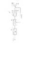
以下、本発明の好ましい実施形態について、添付図面を参照して説明する。図1は、本発明の実施形態である楽器用スピーカ装置1の電気的構成を示すブロック図である。楽器用スピーカ装置1は、入力端子(インプット)と、プリアンプ部10と、フィードバック部20と、パワーアンプ部30と、スピーカ部40とにより構成されている。入力端子51(図2参照)には、主として電気ギター、電気ベース、電子キーボード、電子ピアノなどのライン出力が、接続コードにより接続される。 Hereinafter, preferred embodiments of the present invention will be described with reference to the accompanying drawings. FIG. 1 is a block diagram showing an electrical configuration of a musical
入力端子に入力された電気信号は、プリアンプ部10により周波数特性やレベルが調整され、フィードバック部20に出力される。フィードバック部20は、プリアンプ部10の出力と、スピーカ部40に備えられたボイスコイル41(図3参照)の変位を検出するセンサ45(図3参照)が出力するセンサ出力とを入力し、これらの出力を処理してパワーアンプ部30に出力する。 The electrical signal input to the input terminal is adjusted in frequency characteristics and level by the
パワーアンプ部30は、フィードバック部20の出力をスピーカ部40を駆動する電力増幅を行ってスピーカ部40に出力する。スピーカ部40は、パワーアンプ部30から供給される電力に従ってボイスコイルが振動し、楽音を発生するとともに、ボイスコイル41の機械的振動がセンサ45により検出される。 The
次に、図2を参照してこの楽器用スピーカ装置1の操作パネル50について説明する。図2は、楽器用スピーカ装置1の操作パネル50を示す操作パネル図である。操作パネル50には、入力端子51と、周波数特性を調整するイコライザ12の操作子であるベース調整つまみ52と、ミドル調整つまみ53と、トレブル調整つまみ54と、センサ45の出力の帰還量を調整するMFBレベル調整つまみ55と、プリアンプ部10の出力のレベルを検出し、そのレベルに応じてセンサ45の出力の帰還量を変更する場合の、検出されたプリアンプ部10の出力レベルを調節するダイナミクスセンスつまみ56と音量を調整するボリュームつまみ57とが備えられている。 Next, an
入力端子51は、入力ジャックにより形成され、楽器の出力が接続されたプラグが着脱自在に装着されるものである。ベース調整つまみ52と、ミドル調整つまみ53と、トレブル調整つまみ54とは、それぞれ、イコライザ12が調整する周波数特性の、低音域、中音域、高音域のレベルをそれぞれ調整するものである。これらのつまみには、回転型の可変抵抗器の軸が固着され、可変抵抗器の抵抗値が変化することにより各帯域のレベルが調整される。MFBレベル調整つまみ55と、ダイナミクスセンスつまみ56、ボリュームつまみ57も同様に回転型の可変抵抗器の軸が固着され、可変抵抗器の抵抗値が変化することによりそれぞれの値が調整される。 The
次に、図3を参照してスピーカ部40について説明する。図2は、スピーカ部40の断面を示す断面図である。スピーカ部40は、コーンスピーカといわれるタイプのスピーカであって、主に、ボイスコイル41と、コーン紙42と、マグネット43と、反射板44と、センサ45と、サスペンション47と、フレーム48などにより構成されている。 Next, the
ボイスコイル41は、円筒形に形成され、マグネット43が形成する磁界中において、その円筒の軸に沿って振動可能に配置されている。パワーアンプ部30から供給される電力によりボイスコイル41に電流が流れ、ボイスコイル41は、その電流に応じて振動する。ボイスコイル41には、コーン紙42が固着されボイスコイル41が振動することにより振動し、コーン紙42が空気を振動させることにより楽音が発生される。ボイスコイル41およびコーン紙42は、サスペンション47により、スピーカ部40の外周を形成するフレーム48の中央に保持されている。 The
コーン紙42の中央部分には、ボイスコイル41を覆うようにセンターキャップ46が形成されている。円筒形のボイスコイル41のセンターキャップ46に近い側には、光を反射する反射板44が形成され、ボイスコイル41の振動に応じて変位するように形成されている。 A
円筒形のマグネット43の中心部分は、マグネット43と同心円の円筒形の空間を有し、その円筒形の空間の延長線上で、反射板44に対向する位置に、反射板44に向けて光りを照射する光源と、反射板44により反射された光を受光する受光素子とが備えられたセンサ45が備えられている。図示しないが、このセンサ45は、フレーム48に固着されている。 The central portion of the
光源は、楽器用スピーカ装置1の電源がオンされている間、常に反射板44に向けて光りを照射し、反射板44は、センサ45側が鏡面仕上げされているため、光源により照射された光を反射する。受光素子は反射板44により反射された光の量に応じた電気信号を発生するフォトトランジスタなどにより構成され、センサ45と反射板44との距離が近いほど大きな電圧を出力する。したがって、ボイスコイル41に、音声などの電気信号が供給されると、その信号に応じて振動し、ボイスコイル41の位置に応じた出力をセンサ45は、出力する。 The light source always emits light toward the
なお、従来、反射板をセンターキャップに固着し、その反射板により反射された光によりスピーカの振動を検出するものが知られているが、センターキャップは、振動により歪む場合があったり、センターキャップに反射板を固着することにより、センターキャップの音圧特性が変化するなどの問題点があったが、反射板をボイスコイルの中央に固着することによりこれらの問題点を解決することができる。 Conventionally, it is known that a reflector is fixed to a center cap and the vibration of the speaker is detected by light reflected by the reflector. However, the center cap may be distorted by vibration, or the center cap. There is a problem that the sound pressure characteristic of the center cap is changed by fixing the reflector to the center, but these problems can be solved by fixing the reflector to the center of the voice coil.
次に、図4を参照してプリアンプ部10とフィードバック部20の詳細について説明する。図4は、プリアンプ部10とフィードバック部20の詳細な電気的構成を示すブロック図である。プリアンプ部10は、主にヘッドアンプ11と、イコライザ12と、ボリューム(可変抵抗器)13とにより構成され、入力端子51に入力された電気信号は、ヘッドアンプ11により、所定のレベルに増幅され、次にイコライザ12により周波数特性が変更される。この周波数特性は、操作パネル50に備えられたベース調整つまみ52と、ミドル調整つまみ53と、トレブル調整つまみ54とにより演奏者により任意に設定された特性である。イコライザ12により周波数特性が変更された電気信号は、ボリュームつまみ57により設定されるボリューム値によりレベルが調整される。 Next, details of the
フィードバック部20は、主にローパスフィルタ21と、レベル検出器22と、入出力関数調整部23と、ダイナミクスセンス調整ボリューム29と、ヘッドアンプ24と、フィルタ25と、MFBレベル調整ボリューム28と、電圧制御増幅器(VCA)26と、差動増幅器27とにより構成されている。 The
プリアンプ部10の出力は、差動増幅器27の正極入力に入力されるとともに、ローパスフィルタ21に入力される。ローパスフィルタ21は、例えば、カットオフ周波数が100Hzに設定された低域通過フィルタであって、低域の成分のみがレベル検出器22に入力される。レベル検出器22は、入力信号を全波整流して絶対値を取り、更にローパスフィルタを掛けることにより入力信号の振幅のエンベロープを検出するものである。 The output of the
入出力関数調整部23は、入力値に対する出力値を変換するもので、図5に示すような複数の変換曲線のいずれかの曲線に従って変換するようになされている。 The input / output
図5は、入出力関数調整部23が有する複数の変換曲線を示すグラフである。図5において、aに示す変換曲線は、下に凸の変換特性であって、入力値が小さい場合は、入力値の増分に対する出力値の増分である増加率が小さく、入力値が大きい場合は、増加率が大きい。また、bに示す変換曲線は、上に凸の変換特性であって、入力値が小さい場合は増加率が大きく、入力値が大きい場合は、増加率が小さい。これら二つの変換曲線は、入力レベルが大きいほど出力レベルが大きくなるが、c,dで示す変換曲線では、入力レベルが大きいほど出力レベルが小さくなるものである。cに示す変換曲線は、上に凸の変換特性であって、入力値が小さい場合は、入力値の増分に対する出力値の減少分である減少率が小さく、入力値が大きい場合は、減少率が大きい。また、dに示す変換曲線は、下に凸の変換特性であって、入力値が小さい場合は、減少率が大きく、入力値が大きい場合は、減少率が小さい。 FIG. 5 is a graph showing a plurality of conversion curves that the input / output
入出力関数調整部23により調整されたレベルは、ダイナミクスセンス調整ボリューム29により調整されて、電圧制御増幅器26の制御端子に供給される。 The level adjusted by the input / output
一方、センサ45の出力は、ヘッドアンプ24により所定のレベルに増幅されてフィルタ25に入力される。このフィルタ25は、2次微分フィルタであって、センサ45が検出したボイスコイル41の変位から加速度を取得するものである。これはコーンスピーカの音圧特性は、コーンの加速度に比例するからである。なお、圧電素子などを用いてコーン紙の加速度に比例した電圧を検出する場合には、このフィルタ25は、不要である。 On the other hand, the output of the
フィルタ25の出力は、MFBレベル調整ボリューム28を演奏者が操作することにより任意のレベルに調整され、電圧制御増幅器26の入力端子に入力される。電圧制御増幅器26は、制御端子に供給される電圧値により、入力端子に入力された信号を増幅する増幅率が制御される増幅器である。電圧制御増幅器26の出力は、差動増幅器27の負極端子に入力され、差動増幅器は、正極入力と負極入力との電圧差を増幅し出力するものである。 The output of the
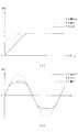
次に、図6を参照して、上記のように構成された楽器用スピーカ装置1において、MFBレベル調整ボリューム28等によりフィードバック量が調整された場合の特性について説明する。図6は、MFBレベル調整ボリューム28等によりフィードバック量が調整された場合の特性を示すグラフであって、図6(a)は、周波数特性を、図(b)は、出力波形をそれぞれ示すものである。 Next, characteristics when the feedback amount is adjusted by the MFB
図6(a)は、横軸を周波数とし、縦軸をスピーカ部40が発生する音圧のレベルを示すもので、実線は、フィードバック量がゼロである場合、破線は、フィードバック量が小さい場合、一点鎖線は、フィードバック量が大きい場合の周波数特性をそれぞれ示す。フィードバック量が小さい場合および大きい場合は、中高域の水平な部分のレベルが下がるが、この図6(a)では、増幅器のゲインを上げて、水平分が同一になるものとして示している。図4に示すブロック図では、図示していないが、例えばプリアンプ部10の出力レベルをMFBレベル28に比例して制御するアンプを設けてもよい。 FIG. 6A shows the sound pressure level generated by the
フィードバック量がゼロの場合は、かなり高い周波数から左肩下がりの特性となり、フィードバック量が小さい場合は、やや高い周波数から左肩下がりの特性となり、フィードバック量が大きい場合は、更に低い周波数から左肩下がりの特性となることが示されてる。図6(b)は、横軸を時間とし、縦軸をスピーカ部40が発生する音圧のレベルを示すもので、入力に例えば、50Hzのサイン波を入力した場合を示し、実線は、フィードバック量がゼロである場合、破線は、フィードバック量が小さい場合、一点鎖線は、フィードバック量が大きい場合の出力波形をそれぞれ示す。フィードバック量がゼロの場合は、サイン波のレベルが比較的低い部分でレベルが押し下げられ、フィードバック量が小さい場合は、やや高いレベルでレベルが押し下げられ、フィードバック量が大きい場合は、ほぼ忠実にサイン波を再生することが示されている。 When the amount of feedback is zero, the characteristic starts from the very high frequency to the left side, when the amount of feedback is small, the characteristic goes from the slightly higher frequency to the left side, and when the feedback amount is large, the characteristic goes from the lower frequency to the left side. It has been shown that In FIG. 6B, the horizontal axis represents time, and the vertical axis represents the level of sound pressure generated by the
以上、実施形態に基づいて説明したように、スピーカ部40の機械的振動を検出し、その検出した値を帰還して増幅器によりスピーカ部40を駆動する楽器用スピーカ装置1において、帰還量を任意に設定するMFBレベル調整ボリューム28を備えたので、特に低音域を再生する場合に、歪みのない楽音を形成することができるとともに、演奏者にとり最適な音色の楽音を形成することができる。 As described above based on the embodiment, in the musical
また、プリアンプ部10の出力レベルに応じて、帰還量を制御することができるので、出力レベルが大きい場合に、帰還量を少なくし、パワーアンプ部30により発生する歪みを少なくすることができる。 Further, since the feedback amount can be controlled according to the output level of the
以上、実施形態に基づき本発明を説明したが、本発明は上述した実施形態に何ら限定されるものではなく、本発明の趣旨を逸脱しない範囲内で種々の改良変更が可能であることは容易に推察できるものである。 Although the present invention has been described based on the embodiments, the present invention is not limited to the above-described embodiments, and various improvements and modifications can be easily made without departing from the spirit of the present invention. Can be inferred.
例えば、上記実施形態では、プリアンプ部10およびフィードバック部20は、アナログ回路により構成されるものとしたが、入力端子に入力されるアナログ電気信号を、所定のサンプリング周波数でデジタル信号に変換するA/D変換器と、センサ45の出力、イコライザ12のボリューム、MFBレベル調整ボリューム28、ダイナミクスセンス調整ボリューム29などにより設定された値をデジタル信号に変換するA/D変換器と、これらのA/D変換器により変換されたデジタル信号を入力し、プリアンプ部10およびフィードバック部における処理を行うDSP(デジタル信号処理装置)と、そのDSPにより処理され出力されるデジタル信号をアナログ信号に変換するD/A変換器とを備え、上記実施形態と同一の処理を行うようにしてもよい。 For example, in the above-described embodiment, the
また、上記実施形態では、フィードバック部20において、ローパスフィルタ21と、レベル検出器22と、入出力関数調整部23と、ダイナミクスセンス調整ボリューム29とを備え、プリアンプ部10の出力を検出して、その検出した値によりセンサ45の出力レベルを制御するものとしたが、単純にヘッドアンプ24と、フィルタ25と、MFBレベル調整ボリューム28と、差動増幅器27だけを有し、差動増幅器27は、プリアンプ部10の出力を正極端子に入力し、MFBレベル調整ボリューム28により調整されたセンサ45の出力を負極端子に入力するようにしてもよい。 In the above embodiment, the
また、上記実施形態では、入出力関数調整部23は、プリアンプ部10の出力の検出レベルを変換するものとしたが、センサ45により検出された値を入出力関数調整部23により変換し、その変換された値を差動増幅器27に供給するようにしてもよい。 In the above embodiment, the input / output
また、上記実施形態では、プリアンプ部10の出力を検出し、その検出したレベルに応じてセンサ45の出力を調整するように構成したが、ボリューム13により設定された値を検出し、その値に応じてセンサ45の出力を調整するようにしてもよい。 In the above embodiment, the output of the
また、上記実施形態では、プリアンプ部10の出力を検出し、その検出したレベルに応じてセンサ45の出力を調整するように構成したが、イコライザ12のベース、ミドル、トレブルのいずれかのボリュームにより設定された値、または、これらの複数のボリュームの設定の組み合わせにより設定された値に応じてセンサ45の出力を調整するようにしてもよい。 In the above embodiment, the output of the
1 楽器用スピーカ装置
10 プリアンプ部(プリアンプ)
12 イコライザ
20 フィードバック部
21ローパスフィルタ(帰還量制御手段の一部、レベル増加手段の一部)
22入出力関数調整部(帰還量制御手段の一部、レベル増加手段の一部、変換手段)
26 電圧制御増幅器(帰還量制御手段の一部)
27差動増幅器(フィードバック処理手段)
28 MFBレベル調整ボリューム
29 ダイナミクスセンス調整ボリューム(帰還量制御手段の一部、レベル増加手段の一部、センス調整手段)
30 パワーアンプ部(パワーアンプ)
40 スピーカ部(スピーカ)
43ボイスコイル
44 反射板
45 光センサ(検出手段、光源と受光素子)
52ベース調整つまみ(イコライザ操作子)
53ミドル調整つまみ(イコライザ操作子)
54トレブル調整つまみ(イコライザ操作子)
57ボリュームつまみ(ボリューム操作子)1 Musical
12
21Low-pass filter (part of feedback control means, part of level increase means)
22 I/ O function adjustment unit (part of feedback amount control means, part of level increase means, conversion means)
26 Voltage control amplifier (part of feedbackcontrol means)
27differential amplifier (feedback processing means)
28 MFB
30 Power Amplifier (Power Amplifier )
40 Speaker section(speaker)
43
52base adjustment knob (equalizer operator)
53middle adjustment knob (equalizer operator)
54treble adjustment knob (equalizer operator)
57Volume knob (volume control)
Claims (9)
Translated fromJapaneseその入力端子に入力された電気信号の周波数特性及びレベルを調整するプリアンプと、
前記入力端子に入力された電気信号に基づいて、スピーカを駆動するパワーアンプと、
そのパワーアンプにより駆動されるスピーカと、
そのスピーカの変位を検出し、検出された変位に応じた信号を出力する検出手段と、
その検出手段から出力された信号を帰還する帰還手段と、
前記プリアンプの出力を受け、その出力レベルに基づいて、前記帰還手段から帰還された帰還信号の量を制御して出力する帰還量制御手段と、
前記プリアンプから出力された、前記入力端子に入力された電気信号を、前記帰還量制御手段から出力される帰還信号の量に応じて増幅して前記パワーアンプへ出力するフィードバック処理手段とを備えた楽器用スピーカ装置であって、
前記帰還量制御手段は、前記帰還量制御手段が受ける前記プリアンプの出力レベルを増加させることができるレベル増加手段を備え、そのレベル増加手段により前記プリアンプの出力レベルが増加された場合に、その増加に応じて、出力する帰還信号の量を大きくするものであることを特徴とする楽器用スピーカ装置。An input terminal for inputting an electrical signal;
A preamplifierfor adjusting the frequency characteristicsand level of the electric signal input to the input terminal;
A power amplifier that drives a speaker based on the electrical signal input to the input terminal;
A speaker driven bythe power amplifier ;
Detecting means for detecting displacement of the speaker and outputtinga signal corresponding to thedetected displacement ;
A feedback means for changingthe null the signal output from the detection means,
Feedback amount control means for receiving the output of the preamplifier and controlling and outputting the amount of feedback signal fed back from the feedback means based on the output level;
Feedback processing means for amplifying the electrical signal output from the preamplifier and input to the input terminal according to the amount of feedback signal output from the feedback amount control means, and outputting the amplified signal to the power amplifier . A speaker device for a musical instrument,
The feedback amount control means includes level increasing means capable of increasing the output level of the preamplifier received by the feedback amount control means, and the increase when the output level of the preamplifier is increased by the level increasing means. A loudspeaker device for musical instruments, which increases the amount of feedback signal to be output in response to the above .
前記帰還量制御手段は、そのボリューム操作子により設定された値に応じて前記帰還信号の量を制御するものであることを特徴とする請求項1から4のいずれかに記載の楽器用スピーカ装置。A volume controller for arbitrarily setting the volume of the sound output from the speaker;
The feedback amountcontrol means, instrument speaker apparatus according to any one of claims 1 to 4, characterized in thatcontrols the amountofthe feedbacksignal in response tothe value set bythe volume operator .
前記帰還量制御手段は、そのイコライザ操作子により設定された値に応じて前記帰還信号の量を制御するものであることを特徴とする請求項1から5のいずれかに記載の楽器用スピーカ装置。The preamplifier includes an equalizer operator that arbitrarily sets levels of a plurality of frequency bands,
The feedback amountcontrol means, instrument speaker apparatus according to any one of claims 1 to 5, characterized in that tocontrol the amountofthe feedbacksignal in response tothe value set bythe equalizer operator .
前記検出手段は、前記反射板に向かって光を照射する光源と、その反射板により反射された光を受光する受光素子とを備えていることを特徴とする請求項1から6のいずれかに記載の楽器用スピーカ装置。The speaker includes a voice coil having a reflector at the center of a cylindrical shape,
The said detection means is equipped with the light source which irradiates light towardthe said reflecting plate, and the light receiving element which light-receives the light reflected by the reflecting plate, The any one of Claim 1 to 6 characterized by the above-mentioned. The loudspeaker device for musical instruments described.
その入力端子に入力された電気信号の周波数特性及びレベルを調整するプリアンプと、A preamplifier for adjusting the frequency characteristics and level of the electric signal input to the input terminal;
前記入力端子に入力された電気信号に基づいて、スピーカを駆動するパワーアンプと、A power amplifier that drives a speaker based on the electrical signal input to the input terminal;
そのパワーアンプにより駆動されるスピーカと、A speaker driven by the power amplifier;
そのスピーカの変位を検出し、検出された変位に応じた信号を出力する検出手段と、Detecting means for detecting displacement of the speaker and outputting a signal corresponding to the detected displacement;
その検出手段から出力された信号を帰還する帰還手段と、Feedback means for feeding back the signal output from the detection means;
前記スピーカが出力する音声の音量を任意に設定するボリューム操作子と、A volume controller for arbitrarily setting the volume of the sound output from the speaker;
そのボリューム操作子により設定された値に応じて前記帰還手段から帰還された帰還信号の量を制御して出力する帰還量制御手段と、Feedback amount control means for controlling and outputting the amount of feedback signal fed back from the feedback means according to the value set by the volume operator;
前記プリアンプから出力された、前記入力端子に入力された電気信号を、前記帰還量制御手段から出力される帰還信号の量に応じて増幅して前記パワーアンプへ出力するフィードバック処理手段とを備えていることを特徴とする楽器用スピーカ装置。Feedback processing means for amplifying the electrical signal output from the preamplifier and input to the input terminal according to the amount of feedback signal output from the feedback amount control means, and outputting the amplified signal to the power amplifier. A loudspeaker device for musical instruments.
その入力端子に入力された電気信号の周波数特性及びレベルを調整するプリアンプと、A preamplifier for adjusting the frequency characteristics and level of the electric signal input to the input terminal;
前記入力端子に入力された電気信号に基づいて、スピーカを駆動するパワーアンプと、A power amplifier that drives a speaker based on the electrical signal input to the input terminal;
そのパワーアンプにより駆動されるスピーカと、A speaker driven by the power amplifier;
そのスピーカの変位を検出し、検出された変位に応じた信号を出力する検出手段と、Detecting means for detecting displacement of the speaker and outputting a signal corresponding to the detected displacement;
その検出手段から出力された信号を帰還する帰還手段と、Feedback means for feeding back the signal output from the detection means;
その帰還手段から帰還された帰還信号の量を制御して出力する帰還量制御手段と、Feedback amount control means for controlling and outputting the amount of feedback signal fed back from the feedback means;
前記プリアンプから出力された、前記入力端子に入力された電気信号を、前記帰還量制御手段から出力される帰還信号の量に応じて増幅して前記パワーアンプへ出力するフィードバック処理手段とを備えた楽器用スピーカ装置であって、Feedback processing means for amplifying the electrical signal output from the preamplifier and input to the input terminal according to the amount of feedback signal output from the feedback amount control means, and outputting the amplified signal to the power amplifier. A speaker device for a musical instrument,
前記プリアンプは、複数の周波数帯域のレベルをそれぞれ任意に設定するイコライザ操作子を備え、The preamplifier includes an equalizer operator that arbitrarily sets levels of a plurality of frequency bands,
前記帰還量制御手段は、そのイコライザ操作子により設定された値に応じて、出力する帰還信号の量を制御するものであることを特徴とする楽器用スピーカ装置。The musical instrument speaker device characterized in that the feedback amount control means controls the amount of feedback signal to be output in accordance with a value set by the equalizer operator.
Priority Applications (2)
| Application Number | Priority Date | Filing Date | Title |
|---|---|---|---|
| JP2005271432AJP4519041B2 (en) | 2005-09-20 | 2005-09-20 | Speaker device for musical instrument |
| US11/523,303US7912233B2 (en) | 2005-09-20 | 2006-09-19 | Speaker system for musical instruments |
Applications Claiming Priority (1)
| Application Number | Priority Date | Filing Date | Title |
|---|---|---|---|
| JP2005271432AJP4519041B2 (en) | 2005-09-20 | 2005-09-20 | Speaker device for musical instrument |
Publications (2)
| Publication Number | Publication Date |
|---|---|
| JP2007086109A JP2007086109A (en) | 2007-04-05 |
| JP4519041B2true JP4519041B2 (en) | 2010-08-04 |
Family
ID=37901974
Family Applications (1)
| Application Number | Title | Priority Date | Filing Date |
|---|---|---|---|
| JP2005271432AExpired - Fee RelatedJP4519041B2 (en) | 2005-09-20 | 2005-09-20 | Speaker device for musical instrument |
Country Status (2)
| Country | Link |
|---|---|
| US (1) | US7912233B2 (en) |
| JP (1) | JP4519041B2 (en) |
Families Citing this family (79)
| Publication number | Priority date | Publication date | Assignee | Title |
|---|---|---|---|---|
| US20070189572A1 (en)* | 2006-01-30 | 2007-08-16 | Eugene Stanley Juall | Loudspeaker system for acoustic instruments and method therefor |
| US20100215198A1 (en)* | 2009-02-23 | 2010-08-26 | Ngia Lester S H | Headset assembly with ambient sound control |
| US8401207B2 (en)* | 2009-03-31 | 2013-03-19 | Harman International Industries, Incorporated | Motional feedback system |
| JP5321263B2 (en)* | 2009-06-12 | 2013-10-23 | ソニー株式会社 | Signal processing apparatus and signal processing method |
| JP2011019209A (en)* | 2009-06-12 | 2011-01-27 | Sony Corp | Signal processing apparatus and signal processing method |
| US8239047B1 (en)* | 2009-07-15 | 2012-08-07 | Bryan Bergeron | Systems and methods for indirect control of processor enabled devices |
| US9067132B1 (en) | 2009-07-15 | 2015-06-30 | Archetype Technologies, Inc. | Systems and methods for indirect control of processor enabled devices |
| US8385585B2 (en)* | 2009-09-17 | 2013-02-26 | Samsung Electronics Co., Ltd. | Speaker |
| US20110148197A1 (en)* | 2009-12-21 | 2011-06-23 | Maurilio Hernandez | In-line uninterruptible power supply |
| JP2012186676A (en) | 2011-03-07 | 2012-09-27 | Sony Corp | Signal processing device and signal processing method |
| US10034109B2 (en)* | 2015-04-09 | 2018-07-24 | Audera Acoustics Inc. | Acoustic transducer systems with position sensing |
| US10142754B2 (en)* | 2016-02-22 | 2018-11-27 | Sonos, Inc. | Sensor on moving component of transducer |
| US9826306B2 (en) | 2016-02-22 | 2017-11-21 | Sonos, Inc. | Default playback device designation |
| US9947316B2 (en) | 2016-02-22 | 2018-04-17 | Sonos, Inc. | Voice control of a media playback system |
| US10095470B2 (en) | 2016-02-22 | 2018-10-09 | Sonos, Inc. | Audio response playback |
| US9811314B2 (en) | 2016-02-22 | 2017-11-07 | Sonos, Inc. | Metadata exchange involving a networked playback system and a networked microphone system |
| US9965247B2 (en) | 2016-02-22 | 2018-05-08 | Sonos, Inc. | Voice controlled media playback system based on user profile |
| US10264030B2 (en) | 2016-02-22 | 2019-04-16 | Sonos, Inc. | Networked microphone device control |
| US9978390B2 (en) | 2016-06-09 | 2018-05-22 | Sonos, Inc. | Dynamic player selection for audio signal processing |
| US10134399B2 (en) | 2016-07-15 | 2018-11-20 | Sonos, Inc. | Contextualization of voice inputs |
| US10152969B2 (en) | 2016-07-15 | 2018-12-11 | Sonos, Inc. | Voice detection by multiple devices |
| US10115400B2 (en) | 2016-08-05 | 2018-10-30 | Sonos, Inc. | Multiple voice services |
| US9942678B1 (en) | 2016-09-27 | 2018-04-10 | Sonos, Inc. | Audio playback settings for voice interaction |
| US9743204B1 (en) | 2016-09-30 | 2017-08-22 | Sonos, Inc. | Multi-orientation playback device microphones |
| US10181323B2 (en) | 2016-10-19 | 2019-01-15 | Sonos, Inc. | Arbitration-based voice recognition |
| US11183181B2 (en) | 2017-03-27 | 2021-11-23 | Sonos, Inc. | Systems and methods of multiple voice services |
| US10475449B2 (en) | 2017-08-07 | 2019-11-12 | Sonos, Inc. | Wake-word detection suppression |
| US10048930B1 (en) | 2017-09-08 | 2018-08-14 | Sonos, Inc. | Dynamic computation of system response volume |
| US10446165B2 (en) | 2017-09-27 | 2019-10-15 | Sonos, Inc. | Robust short-time fourier transform acoustic echo cancellation during audio playback |
| US10482868B2 (en) | 2017-09-28 | 2019-11-19 | Sonos, Inc. | Multi-channel acoustic echo cancellation |
| US10621981B2 (en) | 2017-09-28 | 2020-04-14 | Sonos, Inc. | Tone interference cancellation |
| US10051366B1 (en) | 2017-09-28 | 2018-08-14 | Sonos, Inc. | Three-dimensional beam forming with a microphone array |
| US10466962B2 (en) | 2017-09-29 | 2019-11-05 | Sonos, Inc. | Media playback system with voice assistance |
| US10880650B2 (en) | 2017-12-10 | 2020-12-29 | Sonos, Inc. | Network microphone devices with automatic do not disturb actuation capabilities |
| US10818290B2 (en) | 2017-12-11 | 2020-10-27 | Sonos, Inc. | Home graph |
| CN108235186B (en)* | 2017-12-29 | 2021-08-06 | 广州时艺音响科技有限公司 | Feedback output speaker and feedback output adjusting method |
| US11343614B2 (en) | 2018-01-31 | 2022-05-24 | Sonos, Inc. | Device designation of playback and network microphone device arrangements |
| US11175880B2 (en) | 2018-05-10 | 2021-11-16 | Sonos, Inc. | Systems and methods for voice-assisted media content selection |
| US10847178B2 (en) | 2018-05-18 | 2020-11-24 | Sonos, Inc. | Linear filtering for noise-suppressed speech detection |
| US10959029B2 (en) | 2018-05-25 | 2021-03-23 | Sonos, Inc. | Determining and adapting to changes in microphone performance of playback devices |
| US20190392641A1 (en)* | 2018-06-26 | 2019-12-26 | Sony Interactive Entertainment Inc. | Material base rendering |
| US10681460B2 (en) | 2018-06-28 | 2020-06-09 | Sonos, Inc. | Systems and methods for associating playback devices with voice assistant services |
| US11076035B2 (en) | 2018-08-28 | 2021-07-27 | Sonos, Inc. | Do not disturb feature for audio notifications |
| US10461710B1 (en) | 2018-08-28 | 2019-10-29 | Sonos, Inc. | Media playback system with maximum volume setting |
| US10878811B2 (en) | 2018-09-14 | 2020-12-29 | Sonos, Inc. | Networked devices, systems, and methods for intelligently deactivating wake-word engines |
| US10587430B1 (en) | 2018-09-14 | 2020-03-10 | Sonos, Inc. | Networked devices, systems, and methods for associating playback devices based on sound codes |
| US11024331B2 (en) | 2018-09-21 | 2021-06-01 | Sonos, Inc. | Voice detection optimization using sound metadata |
| US10811015B2 (en) | 2018-09-25 | 2020-10-20 | Sonos, Inc. | Voice detection optimization based on selected voice assistant service |
| US11100923B2 (en) | 2018-09-28 | 2021-08-24 | Sonos, Inc. | Systems and methods for selective wake word detection using neural network models |
| US10692518B2 (en) | 2018-09-29 | 2020-06-23 | Sonos, Inc. | Linear filtering for noise-suppressed speech detection via multiple network microphone devices |
| US11899519B2 (en) | 2018-10-23 | 2024-02-13 | Sonos, Inc. | Multiple stage network microphone device with reduced power consumption and processing load |
| EP3654249A1 (en) | 2018-11-15 | 2020-05-20 | Snips | Dilated convolutions and gating for efficient keyword spotting |
| US11183183B2 (en) | 2018-12-07 | 2021-11-23 | Sonos, Inc. | Systems and methods of operating media playback systems having multiple voice assistant services |
| US11132989B2 (en) | 2018-12-13 | 2021-09-28 | Sonos, Inc. | Networked microphone devices, systems, and methods of localized arbitration |
| US10602268B1 (en) | 2018-12-20 | 2020-03-24 | Sonos, Inc. | Optimization of network microphone devices using noise classification |
| US11315556B2 (en) | 2019-02-08 | 2022-04-26 | Sonos, Inc. | Devices, systems, and methods for distributed voice processing by transmitting sound data associated with a wake word to an appropriate device for identification |
| US10867604B2 (en) | 2019-02-08 | 2020-12-15 | Sonos, Inc. | Devices, systems, and methods for distributed voice processing |
| US11120794B2 (en) | 2019-05-03 | 2021-09-14 | Sonos, Inc. | Voice assistant persistence across multiple network microphone devices |
| US11361756B2 (en) | 2019-06-12 | 2022-06-14 | Sonos, Inc. | Conditional wake word eventing based on environment |
| US11200894B2 (en) | 2019-06-12 | 2021-12-14 | Sonos, Inc. | Network microphone device with command keyword eventing |
| US10586540B1 (en) | 2019-06-12 | 2020-03-10 | Sonos, Inc. | Network microphone device with command keyword conditioning |
| US11138969B2 (en) | 2019-07-31 | 2021-10-05 | Sonos, Inc. | Locally distributed keyword detection |
| US11138975B2 (en) | 2019-07-31 | 2021-10-05 | Sonos, Inc. | Locally distributed keyword detection |
| US10871943B1 (en) | 2019-07-31 | 2020-12-22 | Sonos, Inc. | Noise classification for event detection |
| US11189286B2 (en) | 2019-10-22 | 2021-11-30 | Sonos, Inc. | VAS toggle based on device orientation |
| US11200900B2 (en) | 2019-12-20 | 2021-12-14 | Sonos, Inc. | Offline voice control |
| US11562740B2 (en) | 2020-01-07 | 2023-01-24 | Sonos, Inc. | Voice verification for media playback |
| US11556307B2 (en) | 2020-01-31 | 2023-01-17 | Sonos, Inc. | Local voice data processing |
| US11308958B2 (en) | 2020-02-07 | 2022-04-19 | Sonos, Inc. | Localized wakeword verification |
| US11308962B2 (en) | 2020-05-20 | 2022-04-19 | Sonos, Inc. | Input detection windowing |
| US11482224B2 (en) | 2020-05-20 | 2022-10-25 | Sonos, Inc. | Command keywords with input detection windowing |
| US11727919B2 (en) | 2020-05-20 | 2023-08-15 | Sonos, Inc. | Memory allocation for keyword spotting engines |
| US12387716B2 (en) | 2020-06-08 | 2025-08-12 | Sonos, Inc. | Wakewordless voice quickstarts |
| US11698771B2 (en) | 2020-08-25 | 2023-07-11 | Sonos, Inc. | Vocal guidance engines for playback devices |
| US12283269B2 (en) | 2020-10-16 | 2025-04-22 | Sonos, Inc. | Intent inference in audiovisual communication sessions |
| US11984123B2 (en) | 2020-11-12 | 2024-05-14 | Sonos, Inc. | Network device interaction by range |
| US11551700B2 (en) | 2021-01-25 | 2023-01-10 | Sonos, Inc. | Systems and methods for power-efficient keyword detection |
| EP4409933A1 (en) | 2021-09-30 | 2024-08-07 | Sonos, Inc. | Enabling and disabling microphones and voice assistants |
| US12327549B2 (en) | 2022-02-09 | 2025-06-10 | Sonos, Inc. | Gatekeeping for voice intent processing |
Family Cites Families (14)
| Publication number | Priority date | Publication date | Assignee | Title |
|---|---|---|---|---|
| JPS5695195U (en)* | 1979-12-20 | 1981-07-28 | ||
| JPH0129904Y2 (en)* | 1981-01-22 | 1989-09-12 | ||
| JPS58103292A (en)* | 1981-12-15 | 1983-06-20 | Matsushita Electric Ind Co Ltd | MFB speaker |
| JPS5936687A (en) | 1982-08-24 | 1984-02-28 | Sumitomo Chem Co Ltd | 1,3-dithian, its preparation, insecticide and acaricide containing it as active ingredient |
| JPH0671358B2 (en)* | 1985-09-28 | 1994-09-07 | 日本ビクター株式会社 | Remote feed back system |
| JPS6316789A (en) | 1986-07-09 | 1988-01-23 | Matsushita Electric Ind Co Ltd | color demodulation circuit |
| JPS63193698A (en)* | 1987-02-05 | 1988-08-10 | Mitsubishi Electric Corp | Motional feedback type speaker system |
| JPH03104500A (en) | 1989-09-19 | 1991-05-01 | Sharp Corp | Speaker and acoustic reproducing device |
| JPH0440199A (en) | 1990-06-06 | 1992-02-10 | Mitsubishi Electric Corp | Speaker device |
| EP0548836B1 (en)* | 1991-12-20 | 1997-06-11 | Matsushita Electric Industrial Co., Ltd. | A bass reproduction speaker apparatus |
| JP2940587B2 (en) | 1993-03-30 | 1999-08-25 | 株式会社ケンウッド | Speaker vibration detection device |
| US5814752A (en)* | 1997-01-15 | 1998-09-29 | Rivera; Paul E. | Musical instrument crossover circuits and method of using same |
| JPH11215587A (en)* | 1998-01-23 | 1999-08-06 | Onkyo Corp | MFB type audio playback device |
| JP2003087892A (en) | 2001-09-11 | 2003-03-20 | Kenwood Corp | Speaker, speaker system, and speaker control method |
- 2005
- 2005-09-20JPJP2005271432Apatent/JP4519041B2/ennot_activeExpired - Fee Related
- 2006
- 2006-09-19USUS11/523,303patent/US7912233B2/ennot_activeExpired - Fee Related
Also Published As
| Publication number | Publication date |
|---|---|
| US7912233B2 (en) | 2011-03-22 |
| US20070076906A1 (en) | 2007-04-05 |
| JP2007086109A (en) | 2007-04-05 |
Similar Documents
| Publication | Publication Date | Title |
|---|---|---|
| JP4519041B2 (en) | Speaker device for musical instrument | |
| JP6885605B2 (en) | Speaker device and audio device | |
| JP2009188474A5 (en) | ||
| JP2004325908A (en) | Sound collecting device of percussion instrument | |
| JP2013186147A (en) | Signal processing device for stringed instrument | |
| WO2018100754A1 (en) | Acoustic apparatus | |
| US20140208925A1 (en) | Pickup system for cajon percussion instruments | |
| US8796530B2 (en) | Musical instrument with acoustic transducer | |
| US8023665B2 (en) | Microphone-tailored equalizing system | |
| US5866836A (en) | Low frequency sound monitoring system for musicians | |
| KR102531296B1 (en) | Audio signal correction method | |
| KR101757362B1 (en) | Pink noise output method for inspected of acoustic apparatus | |
| JP2008507934A (en) | Speech enhancement | |
| JP6816882B2 (en) | Musical instrument preamplifier | |
| JPH0580748A (en) | Keyboard musical instrument | |
| JP5287328B2 (en) | Percussion instrument | |
| EP1446874B1 (en) | Microphone-tailored equalizing system | |
| KR200452709Y1 (en) | Integrated microphone circuit and structure of the integrated microphone | |
| JP2008299081A (en) | Electronic musical instrument with soundboard | |
| JP2004200934A (en) | Speaker device and method of controlling the same | |
| JP4528280B2 (en) | Musical sound device and musical sound control method. | |
| JP2625801B2 (en) | Electric musical instrument | |
| JP2010271428A (en) | Electronic drum | |
| JP2019078991A (en) | Electric wind instrument | |
| JP2008268777A (en) | Musical sound device and production method and processing method of musical sound device |
Legal Events
| Date | Code | Title | Description |
|---|---|---|---|
| A621 | Written request for application examination | Free format text:JAPANESE INTERMEDIATE CODE: A621 Effective date:20080911 | |
| A131 | Notification of reasons for refusal | Free format text:JAPANESE INTERMEDIATE CODE: A131 Effective date:20100216 | |
| A521 | Request for written amendment filed | Free format text:JAPANESE INTERMEDIATE CODE: A523 Effective date:20100419 | |
| TRDD | Decision of grant or rejection written | ||
| A01 | Written decision to grant a patent or to grant a registration (utility model) | Free format text:JAPANESE INTERMEDIATE CODE: A01 Effective date:20100518 | |
| A01 | Written decision to grant a patent or to grant a registration (utility model) | Free format text:JAPANESE INTERMEDIATE CODE: A01 | |
| A61 | First payment of annual fees (during grant procedure) | Free format text:JAPANESE INTERMEDIATE CODE: A61 Effective date:20100518 | |
| FPAY | Renewal fee payment (event date is renewal date of database) | Free format text:PAYMENT UNTIL: 20130528 Year of fee payment:3 | |
| R150 | Certificate of patent or registration of utility model | Free format text:JAPANESE INTERMEDIATE CODE: R150 | |
| LAPS | Cancellation because of no payment of annual fees |