JP4518044B2 - Thrombus aspiration catheter - Google Patents
Thrombus aspiration catheterDownload PDFInfo
- Publication number
- JP4518044B2 JP4518044B2JP2006152793AJP2006152793AJP4518044B2JP 4518044 B2JP4518044 B2JP 4518044B2JP 2006152793 AJP2006152793 AJP 2006152793AJP 2006152793 AJP2006152793 AJP 2006152793AJP 4518044 B2JP4518044 B2JP 4518044B2
- Authority
- JP
- Japan
- Prior art keywords
- tubular body
- guide wire
- distal end
- aspiration catheter
- thrombus
- Prior art date
- Legal status (The legal status is an assumption and is not a legal conclusion. Google has not performed a legal analysis and makes no representation as to the accuracy of the status listed.)
- Active
Links
Images


Classifications
- A—HUMAN NECESSITIES
- A61—MEDICAL OR VETERINARY SCIENCE; HYGIENE
- A61M—DEVICES FOR INTRODUCING MEDIA INTO, OR ONTO, THE BODY; DEVICES FOR TRANSDUCING BODY MEDIA OR FOR TAKING MEDIA FROM THE BODY; DEVICES FOR PRODUCING OR ENDING SLEEP OR STUPOR
- A61M25/00—Catheters; Hollow probes
- A61M25/0067—Catheters; Hollow probes characterised by the distal end, e.g. tips
- A61M25/0068—Static characteristics of the catheter tip, e.g. shape, atraumatic tip, curved tip or tip structure
- A—HUMAN NECESSITIES
- A61—MEDICAL OR VETERINARY SCIENCE; HYGIENE
- A61B—DIAGNOSIS; SURGERY; IDENTIFICATION
- A61B17/00—Surgical instruments, devices or methods
- A61B17/22—Implements for squeezing-off ulcers or the like on inner organs of the body; Implements for scraping-out cavities of body organs, e.g. bones; for invasive removal or destruction of calculus using mechanical vibrations; for removing obstructions in blood vessels, not otherwise provided for
- A—HUMAN NECESSITIES
- A61—MEDICAL OR VETERINARY SCIENCE; HYGIENE
- A61M—DEVICES FOR INTRODUCING MEDIA INTO, OR ONTO, THE BODY; DEVICES FOR TRANSDUCING BODY MEDIA OR FOR TAKING MEDIA FROM THE BODY; DEVICES FOR PRODUCING OR ENDING SLEEP OR STUPOR
- A61M25/00—Catheters; Hollow probes
- A61M25/0067—Catheters; Hollow probes characterised by the distal end, e.g. tips
- A61M25/008—Strength or flexibility characteristics of the catheter tip
- A—HUMAN NECESSITIES
- A61—MEDICAL OR VETERINARY SCIENCE; HYGIENE
- A61B—DIAGNOSIS; SURGERY; IDENTIFICATION
- A61B17/00—Surgical instruments, devices or methods
- A61B17/32—Surgical cutting instruments
- A61B17/3205—Excision instruments
- A61B17/3207—Atherectomy devices working by cutting or abrading; Similar devices specially adapted for non-vascular obstructions
- A61B17/320783—Atherectomy devices working by cutting or abrading; Similar devices specially adapted for non-vascular obstructions through side-hole, e.g. sliding or rotating cutter inside catheter
- A—HUMAN NECESSITIES
- A61—MEDICAL OR VETERINARY SCIENCE; HYGIENE
- A61B—DIAGNOSIS; SURGERY; IDENTIFICATION
- A61B2217/00—General characteristics of surgical instruments
- A61B2217/002—Auxiliary appliance
- A61B2217/005—Auxiliary appliance with suction drainage system
- A—HUMAN NECESSITIES
- A61—MEDICAL OR VETERINARY SCIENCE; HYGIENE
- A61M—DEVICES FOR INTRODUCING MEDIA INTO, OR ONTO, THE BODY; DEVICES FOR TRANSDUCING BODY MEDIA OR FOR TAKING MEDIA FROM THE BODY; DEVICES FOR PRODUCING OR ENDING SLEEP OR STUPOR
- A61M25/00—Catheters; Hollow probes
- A61M25/0067—Catheters; Hollow probes characterised by the distal end, e.g. tips
- A61M25/0074—Dynamic characteristics of the catheter tip, e.g. openable, closable, expandable or deformable
- A61M25/0075—Valve means
- A61M2025/0076—Unidirectional valves
- A61M2025/0078—Unidirectional valves for fluid inflow from the body into the catheter lumen
- A—HUMAN NECESSITIES
- A61—MEDICAL OR VETERINARY SCIENCE; HYGIENE
- A61M—DEVICES FOR INTRODUCING MEDIA INTO, OR ONTO, THE BODY; DEVICES FOR TRANSDUCING BODY MEDIA OR FOR TAKING MEDIA FROM THE BODY; DEVICES FOR PRODUCING OR ENDING SLEEP OR STUPOR
- A61M25/00—Catheters; Hollow probes
- A61M25/0067—Catheters; Hollow probes characterised by the distal end, e.g. tips
- A61M25/008—Strength or flexibility characteristics of the catheter tip
- A61M2025/0081—Soft tip
- A—HUMAN NECESSITIES
- A61—MEDICAL OR VETERINARY SCIENCE; HYGIENE
- A61M—DEVICES FOR INTRODUCING MEDIA INTO, OR ONTO, THE BODY; DEVICES FOR TRANSDUCING BODY MEDIA OR FOR TAKING MEDIA FROM THE BODY; DEVICES FOR PRODUCING OR ENDING SLEEP OR STUPOR
- A61M25/00—Catheters; Hollow probes
- A61M25/0067—Catheters; Hollow probes characterised by the distal end, e.g. tips
- A61M25/0068—Static characteristics of the catheter tip, e.g. shape, atraumatic tip, curved tip or tip structure
- A61M25/0071—Multiple separate lumens
Landscapes
- Health & Medical Sciences (AREA)
- Life Sciences & Earth Sciences (AREA)
- Animal Behavior & Ethology (AREA)
- Veterinary Medicine (AREA)
- Public Health (AREA)
- Engineering & Computer Science (AREA)
- Biomedical Technology (AREA)
- Heart & Thoracic Surgery (AREA)
- General Health & Medical Sciences (AREA)
- Anesthesiology (AREA)
- Hematology (AREA)
- Pulmonology (AREA)
- Biophysics (AREA)
- Surgery (AREA)
- Orthopedic Medicine & Surgery (AREA)
- Vascular Medicine (AREA)
- Nuclear Medicine, Radiotherapy & Molecular Imaging (AREA)
- Medical Informatics (AREA)
- Molecular Biology (AREA)
- Media Introduction/Drainage Providing Device (AREA)
- Surgical Instruments (AREA)
Abstract
Description
Translated fromJapanese本発明は、経皮的に体内に導入され、血管内に生成した血栓や血管内に遊離したアテローマなどのデブリス(異物)をカテーテル手元端から加える陰圧により体外に吸引除去する血栓吸引カテーテルに関する。 The present invention relates to a thrombus aspiration catheter which is introduced into the body percutaneously and sucks and removes from the body by negative pressure applied from a proximal end of a catheter such as a thrombus generated in a blood vessel or a debris (foreign matter) such as atheroma released in the blood vessel .
血栓性疾患は、急性心筋梗塞に代表する心臓(冠動脈)疾患ばかりではなく、手もしくは足の血管においても起こっており、従来は、外科的な治療によって行われていた治療であるが、近年急速に普及している低侵襲治療であるインターベンション治療(経皮的カテーテル治療術)に置き換わりつつある。これは、外科的治療における侵襲度の高い治療から、治療をうける患者へのQOLが考慮され、低侵襲治療が行われるようになったためである。 Thrombotic diseases occur not only in heart (coronary artery) diseases represented by acute myocardial infarction, but also in the blood vessels of hands or feet. Conventionally, these treatments have been performed by surgical treatment. Is being replaced by interventional treatment (percutaneous catheterization), which is a minimally invasive treatment. This is because, from the highly invasive treatment in the surgical treatment, the QOL to the patient to be treated is taken into consideration, and the minimally invasive treatment is performed.
本発明は、このインターベンション治療の1つである血栓吸引療法に関する。血栓吸引療法は脚や腕といった四肢に詰まった血栓をカテーテルと呼ばれる細い管を挿入し、治療部位に到達させ、血栓そのものを吸引し除去する治療方法である。 The present invention relates to thrombus aspiration therapy which is one of the interventional treatments. Thrombus aspiration therapy is a treatment method in which a thrombus clogged in the limbs such as the legs and arms is inserted into a thin tube called a catheter to reach the treatment site, and the thrombus itself is aspirated and removed.
上記のような血栓を除去する目的のカテーテルは、血栓吸引カテーテルと呼ばれ、吸引具と組み合わせて用いられる。血栓吸引カテーテルにおいては、陰圧によりカテーテル壁面の潰れが生じることの無いよう、ある程度の強度が必要であり、さらに、吸引物を病変部から体外へ排出し易くするために、開口断面における面積(開口面積)をできるだけ大きくする必要があった。 The catheter for the purpose of removing the thrombus as described above is called a thrombus suction catheter, and is used in combination with a suction tool. In the thrombus aspiration catheter, a certain level of strength is necessary so that the catheter wall surface is not crushed by negative pressure. Furthermore, in order to facilitate the discharge of the aspirate from the lesioned area, It was necessary to make the opening area as large as possible.
従来のカテーテルでは、シングルルーメンチューブを用いて、吸引性能を上げる方法が取られているが、ガイドワイヤーを保持するガイドワイヤールーメンを有していないために、カテーテル内径とガイドワイヤー外径とに差があるため、目的の方向へのカテーテル操作の面で難があった。また、心臓に一般的に用いられるラピッドエクスチェンジ型と呼ばれる形状では、カテーテルを進めるシースイントロデューサーの内径に対して、カテーテル外側にガイドワイヤーが来る形状であるために、シースイントロデューサー内径より、ガイドワイヤーの外径の分、カテーテル自身を小さくしなくてはならず、結果吸引ルーメン断面積を小さくするという欠点を有する。(特許文献1、2、3) In conventional catheters, a single lumen tube is used to increase the suction performance. However, since there is no guide wire lumen for holding the guide wire, there is a difference between the catheter inner diameter and the guide wire outer diameter. Therefore, there was a difficulty in the operation of the catheter in the intended direction. Also, in the shape called rapid exchange type generally used for the heart, the guide wire comes to the outside of the catheter with respect to the inner diameter of the sheath introducer that advances the catheter. As a result, the catheter itself must be made smaller by the outer diameter of the tube, resulting in the disadvantage of reducing the suction lumen cross-sectional area. (
そこで、本発明は、従来考えられる形状では相反する機能である吸引ルーメン断面積を大きく取ることによる吸引力の向上とカテーテルとしての操作性の向上を目的とする。 Therefore, the present invention aims to improve the suction force and the operability of the catheter by increasing the suction lumen cross-sectional area, which is a function that is contradictory to the conventional shape.
本発明者らは、上記課題を解決するため鋭意検討を行った結果、先端部分にフック状の短いガイドワイヤーシャフトを設けるとともに、先端部形状を傾斜したカット面とし、血管内および病変部への通過性を良くし、また管状体内にはガイドワイヤーのみが進むことで、余計な吸引ルーメン断面積の縮小化を極力抑えた仕様とした。 As a result of diligent studies to solve the above problems, the present inventors have provided a hook-like short guide wire shaft at the distal end portion and an inclined cut surface at the distal end portion, to the inside of the blood vessel and the lesioned portion. The passage is improved, and only the guide wire is advanced in the tubular body, so that the reduction of the unnecessary suction lumen cross-sectional area is minimized.
すなわち、本発明は、基端から先端まで貫通する吸引ルーメンと、開口を形成する先端部が傾斜したカット面とを有する管状体を含む血栓吸引カテーテルであって、該管状体の先端部のみにガイドワイヤールーメンを有すると共に該ガイドワイヤールーメンが該吸引ルーメンに連通することを特徴とする血栓吸引カテーテルを構成した。
好ましい実例として、カテーテルの軸心に対し先端部が傾斜したカット面により形成された開口は、カット面の先端側においてくびれた形状を有し、カット面の基端側の少なくとも一部が傾斜方向に凹状に形成される。That is, the present invention is a thrombus suction catheter including a tubular body having a suction lumen penetrating from the proximal end to the distal end and a cut surface having an inclined distal end portion forming an opening, and is provided only at the distal end portion of the tubular body. A thrombus aspiration catheter characterized in that it has a guide wire lumen and the guide wire lumen communicates with the aspiration lumen.
As a preferable example, the opening formed by the cut surface whose tip end is inclined with respect to the axial center of the catheter has a constricted shape on the distal end side of the cut surface, and at least a part of the proximal end side of the cut surface is inclined. It is formed in a concave shape.
または、前記ガイドワイヤールーメンは、前記管状体の先端部に設けたガイドワイヤーシャフトに設けられている。さらに、前記管状体の先端部は、X線透視下で位置確認をするための造影剤が練りこまれた樹脂もしくはX線不透過マーカーを有する。または、前記管状体には、金属編みこみもしくはコイルの補強体を有する。さらに、前記管状体に、親水性コーティングが付与されている。加えて、前記菅状体に、先端に向けて柔軟になるように樹脂の硬度の違いにより、複数の段階の硬度差を有する、ここで管状体先端部にはX線透視下で位置確認をするための造影剤が練りこまれた樹脂もしくはX線不透過マーカーを有する。または、前記管状体の先端部の最先端にガイドワイヤールーメンを有する。さらに、前記傾斜したカット面は、前記カット面の先端側において、くびれた形状を有する。加えて、前記カット面の基端側の少なくとも一部が傾斜方向に凹状に形成される。 Or the said guide wire lumen | rumen is provided in the guide wire shaft provided in the front-end | tip part of the said tubular body. Furthermore, the distal end portion of the tubular body has a resin or a radiopaque marker in which a contrast medium for confirming the position under fluoroscopy is incorporated. Alternatively, the tubular body has a metal braid or a coil reinforcement. Further, a hydrophilic coating is applied to the tubular body. In addition, the saddle-shaped body has a plurality of stages of hardness differences due to the difference in the hardness of the resin so as to be flexible toward the distal end. It has a resin or a radiopaque marker kneaded with a contrast medium. Or it has a guide wire lumen at the tip of the tip of the tubular body. Further, the inclined cut surface has a constricted shape on the tip side of the cut surface. In addition, at least a part of the base end side of the cut surface is formed in a concave shape in the inclination direction.
本発明によれば、基端から先端まで貫通する吸引ルーメンと、先端部が傾斜したカット面とを有する管状体を含む血栓吸引カテーテルであって、該管状体の先端部のみにガイドワイヤールーメンを有すると共に該ガイドワイヤールーメンが該吸引ルーメンに連通することにより、従来考えられる形状では相反する機能であった吸引ルーメン断面積を大きく取ることによる吸引力の向上とカテーテルとしての操作性の向上を実現できる。 According to the present invention, there is provided a thrombus suction catheter including a tubular body having a suction lumen penetrating from the proximal end to the distal end and a cut surface having an inclined distal end portion, and the guide wire lumen is provided only at the distal end portion of the tubular body. The guide wire lumen communicates with the suction lumen, and the suction force is improved and the operability as a catheter is improved by taking a large cross-sectional area of the suction lumen, which was a contradictory function in the conventional shape. it can.
または、管状体の先端部は、X線透視下で位置確認をするための造影剤が練りこまれた樹脂もしくはX線不透過マーカーを有することにより、治療中の視認性を向上させることができる。さらに、管状体に、金属編みこみもしくはコイルの補強体を有することにより、管強度を向上させると共に薄肉化が可能となる。さらに、管状体に、親水性コーティングが付与されていることにより、血管壁に対してのカテーテルにおける侵襲を低減すると共に、通過性/操作性の向上することができる。 Alternatively, the distal end portion of the tubular body can improve visibility during treatment by having a resin or a radiopaque marker kneaded with a contrast medium for confirming the position under fluoroscopy. . Furthermore, by providing the tubular body with a braided metal or a coil reinforcement, the tube strength can be improved and the wall thickness can be reduced. Furthermore, since the hydrophilic coating is applied to the tubular body, it is possible to reduce the invasion of the catheter against the blood vessel wall and improve the passability / operability.
加えて、菅状体には、先端に向けて柔軟になるように樹脂の硬度の違いにより、少なくとも3段階の硬度差を有することにより、血管内での病変部位においては、柔軟な硬度とし、通過性と血管へ対する侵襲性を抑える効果があり、基端部では、カテーテル操作時の押し込み時にキンクを起こさずに、押したり引いたり、回転させたりできる。 In addition, the rod-shaped body has a hardness difference of at least three stages due to the difference in the hardness of the resin so as to be flexible toward the tip, so that the lesion in the blood vessel has a flexible hardness, It has the effect of suppressing the passage and invasiveness to blood vessels, and can be pushed, pulled or rotated at the proximal end without causing kinks when pushing in during catheter operation.
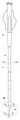
以下に本発明に係る血栓吸引カテーテルの実施形態について説明するが、本発明はこれに限定されるものではない。以下、図面を参照して説明する。図1は、本発明の一実施例の血栓吸引カテーテルの全体を示す正面図である。図2は、図1の先端部Mの拡大断面図である。図3は、図1の先端要部Mの拡大平面図である。図4は、図1のA−A断面図である。図5は、図1のB−B断面図である。図6は、図1のC−C断面図である。 Hereinafter, embodiments of the thrombus aspiration catheter according to the present invention will be described, but the present invention is not limited thereto. Hereinafter, description will be given with reference to the drawings. FIG. 1 is a front view showing an entire thrombus aspiration catheter according to an embodiment of the present invention. FIG. 2 is an enlarged cross-sectional view of the tip M of FIG. FIG. 3 is an enlarged plan view of the tip main part M of FIG. 4 is a cross-sectional view taken along line AA in FIG. 5 is a cross-sectional view taken along the line BB in FIG. 6 is a cross-sectional view taken along the line CC of FIG.
本発明による血栓吸引カテーテル1は、基端から先端まで貫通する吸引ルーメン5を有し、先端部11が傾斜したカット面4を有する管状体2であって、基端にハブ3を有し、先端部11にはガイドワイヤーを追随するためのフック状のガイドワイヤーシャフト6を有する血栓吸引カテーテル1であって、吸引ルーメン5内を進むガイドワイヤーが最先端部に位置するガイドワイヤーシャフト6内のガイドワイヤールーメン7に連通することを特徴とする血栓吸引カテーテル1である。 A thrombus aspiration catheter 1 according to the present invention is a
管状体2の先端部11にガイドワイヤールーメン7を有し、且つ吸引ルーメン5内を進むガイドワイヤーがガイドワイヤールーメン7と連通するいわゆる、オーバーザワイヤー構造であり、術者がガイドワイヤーを血管内病変部末梢部位まで進め、本発明の血栓吸引カテーテル1をガイドワイヤーに沿ってデリバリーすることが可能となる。さらに、先端部11に傾斜したカット面4を有する構造とすることで、先端部分が柔軟となり、また管状体2の基端側よりも細くなることで、血管内の操作性/通過性が向上し、高度屈曲部位や分岐部位に対しての治療を可能とする。
本発明のカテーテルでは、ガイドワイヤールーメンの長さは3〜15mm、直径が0.46〜1.00mmである。ガイドワイヤーシャフトの外径は0.86〜1.40mmである。管状体の内径は1.35〜1.95mm、外径は1.70〜2.30mmである。
ガイドワイヤーの標準直径は0.36mm、0.46mm、0.89mmである。The
In the catheter of the present invention, the guide wire lumen has a length of 3 to 15 mm and a diameter of 0.46 to 1.00 mm. The outer diameter of the guide wire shaft is 0.86 to 1.40 mm. The inner diameter of the tubular body is 1.35 to 1.95 mm, and the outer diameter is 1.70 to 2.30 mm.
Standard diameters of the guide wire are 0.36 mm, 0.46 mm, and 0.89 mm.
ガイドワイヤーシャフト6と管状体2の先端部11との接合方法は、本発明の効果とは何ら制限しない。すなわち、熱融着等の公知の方法もしくは、接着等の公知の方法を用いることで接合してよい。 The joining method of the
管状体2の先端側には、X線透視下で血栓吸引カテーテル1の先端部の位置を確認するために管状体2の先端部11もしくは管状体2の全体に造影剤を練りこんだ樹脂を用いることができる。この造影剤は、酸化ビスマス、硫酸ビスマス、次炭酸ビスマス等の造影剤を樹脂に対して、20%から60%程度の配合されている。 On the distal end side of the
また、先端部11のガイドワイヤーシャフト6には、X線不透過マーカーが付与することがある。X線不透過マーカーの材質は、ステンレス、金、白金、イリジウム等の単体もしくは合金の金属材料が好適に使用できる。 Further, an X-ray opaque marker may be imparted to the
管状体2の先端部11よりも基端側には、吸引時での陰圧におけるカテーテル壁面のつぶれ、カテーテルの押し込み時の力の付与を実現するために、管状体2には、補強体9として金属メッシュによる編みこみもしくはコイル等が巻かれており、管強度を上げるとともに、強度アップによるカテーテル壁厚の薄肉化による吸引ルーメン5の拡大がなされている。補強体9の材料としては、ステンレス、Ti-Ni等の金属材料が好適に使用できる。 To the proximal end side of the
さらに管状体2には、樹脂の硬度の違いにより先端側は、柔軟で基端側にいくほど硬くなるように3段階以上の硬度差を設けている。
これは、血管内での病変部位においては、柔軟な硬度とし、通過性と血管へ対する侵襲性を抑える効果があり、基端部では、カテーテル操作時の押し込み時にキンクを起こさずに、押したり引いたり、回転させたりできる。Further, the
This has the effect of suppressing the permeability and invasiveness to the blood vessel at the lesion site in the blood vessel, and has the effect of suppressing the invasiveness to the blood vessel. Can be pulled or rotated.
好適な構造としては、既に公知技術である造影カテーテル/ガイディングカテーテル等に用いられる構造/加工方法であり、本発明の効果を制限するものではないが、好適な材料構成の1例として、3層構造/2層構造とし内層10にポリアミド、ポリアミドエラストマー、ポリウレタン、ポリウレタンエラストマー、ポリオレフィン、ポリオレフィンエラストマー、ポリエステル、ポリエステルエラストマー等およびフッ素系樹脂としてPTFE,FEP,EPFE、PFA等が用いられ、中間層9に補強体、外層8の材料としては、ポリアミド、ポリアミドエラストマー、ポリウレタン、ポリウレタンエラストマー、ポリオレフィン、ポリオレフィンエラストマー、ポリエステル、ポリエステルエラストマー等が使用できる。 A suitable structure is a structure / processing method used for a contrast catheter / guiding catheter or the like that is already known, and does not limit the effect of the present invention. However, as an example of a suitable material structure, 3 Layer structure / 2-layer
管状体2の先端より基端にかけては、親水性コーティングが付与されていることが望ましい。これは、血管壁に対してのカテーテルにおける侵襲を低減する目的と通過性/操作性の向上を目的とする。 It is desirable that a hydrophilic coating is applied from the distal end to the proximal end of the
親水性コーティングの方法、材質は特に本発明の効果を制限するものではないが、使用する管状体2、ガイドワイヤーシャフト6等の性状に合わせて選択可能であり、例を挙げるとポリ(2−ヒドロキシエチルメタクリレート)、ポリアクリルアミド、ポリビニルピロリドン等の親水性ポリマーが好適に使用できる。 The method and material of the hydrophilic coating are not particularly limited to the effects of the present invention, but can be selected according to the properties of the
以下に本発明の実施例について説明する。
管状体2は、外径2.0mm、内径1.65mm、長さ700mmであり、その構造は内層10にPFA、中間層9にステンレス製平板の編みこみ構造による補強体、外層8に3段階の硬度差を設けたナイロンエラストマー(樹脂硬度40D、55D、72D)を用いたチューブを作製した。Examples of the present invention will be described below.
The
また、先端部分造影剤には、酸化ビスマス40%配合のナイロンエラストマーを用いた。管状体2の先端部11は、剃刀にて斜めにカットして傾斜したカット面4を形成し、ガイドワイヤーシャフト6の外径0.70mm、内径0.55mm、長さ10mmにマンドレルをいれ、先端部11のカットした部分にガイドワイヤーシャフト6を巻きつけるようにし、熱加工によって融着させた後、先端部を整えた。 A nylon elastomer blended with 40% bismuth oxide was used as the tip partial contrast agent. The
管状体2の基端には、ポリカーボネイトを用いて射出成型したハブ3をUV接着剤により接着固定し、さらにカテーテルの先端部より200mmにポリビニルピロリドンによる親水性コーティングを施して、血栓吸引カテーテル1を得た。 At the proximal end of the
尚、上記形態では、ガイドワイヤールーメン7がガイドワイヤーシャフト6内に設けられているが、先端部11をカットした部分の熱加工のみでガイドワイヤールーメン7を形成することも可能である。また、上記形態では、管状体2は柔軟で基端側にいくほど硬くなるように3段階以上の硬度差を設けることが好ましいが、2段階でもあっても良い。 In the above embodiment, the
1 血栓吸引カテーテル
2 管状体
3 ハブ
4 カット面
5 吸引ルーメン
6 ガイドワイヤーシャフト
7 ガイドワイヤールーメン
8 外層
9 中間層
10 内層
11 先端部
DESCRIPTION OF SYMBOLS 1
Claims (8)
Translated fromJapanese開口を形成する先端部が傾斜したカット面と、
を有する管状体を含む血栓吸引カテーテルであって、
該カット面を巻き付けて接合されたガイドワイヤーシャフトを設け、
該ガイドワイヤーシャフトが該吸引ルーメンに連通されるガイドワイヤールーメンを有した血栓吸引カテーテル。A suction lumen penetrating from the proximal end to the distal end;
A cut surface with an inclined tip forming an opening;
A thrombus aspiration catheter comprising a tubular body having
Provide a guide wire shaft joined bywinding the cut surface,
A thrombus aspiration catheter having a guide wire lumen in which the guide wire shaft communicates with the aspiration lumen.
Priority Applications (1)
| Application Number | Priority Date | Filing Date | Title |
|---|---|---|---|
| JP2006152793AJP4518044B2 (en) | 2005-06-01 | 2006-05-31 | Thrombus aspiration catheter |
Applications Claiming Priority (2)
| Application Number | Priority Date | Filing Date | Title |
|---|---|---|---|
| JP2005162005 | 2005-06-01 | ||
| JP2006152793AJP4518044B2 (en) | 2005-06-01 | 2006-05-31 | Thrombus aspiration catheter |
Publications (2)
| Publication Number | Publication Date |
|---|---|
| JP2007007388A JP2007007388A (en) | 2007-01-18 |
| JP4518044B2true JP4518044B2 (en) | 2010-08-04 |
Family
ID=36831245
Family Applications (1)
| Application Number | Title | Priority Date | Filing Date |
|---|---|---|---|
| JP2006152793AActiveJP4518044B2 (en) | 2005-06-01 | 2006-05-31 | Thrombus aspiration catheter |
Country Status (6)
| Country | Link |
|---|---|
| US (1) | US20060276774A1 (en) |
| EP (1) | EP1728531B1 (en) |
| JP (1) | JP4518044B2 (en) |
| AT (1) | ATE451136T1 (en) |
| DE (1) | DE602006010937D1 (en) |
| ES (1) | ES2335522T3 (en) |
Families Citing this family (13)
| Publication number | Priority date | Publication date | Assignee | Title |
|---|---|---|---|---|
| JP4409179B2 (en)* | 2003-01-22 | 2010-02-03 | ニプロ株式会社 | Thrombus aspiration catheter with improved suction and crossability |
| US8317773B2 (en)* | 2006-11-07 | 2012-11-27 | Angio Dynamics, Inc. | Catheter with open faced sloped end portion |
| WO2008123521A1 (en)* | 2007-04-03 | 2008-10-16 | Nipro Corporation | Thrombus-aspiration catheter |
| US7938794B2 (en)* | 2007-05-04 | 2011-05-10 | Sscor, Inc. | Airway suction spoon |
| JP5822140B2 (en)* | 2012-03-27 | 2015-11-24 | ニプロ株式会社 | Thrombus aspiration catheter |
| WO2014176332A1 (en)* | 2013-04-23 | 2014-10-30 | Gmedix, Inc. | Thrombus extraction catheter |
| KR101624543B1 (en)* | 2014-10-23 | 2016-06-07 | 장상훈 | Suction catheter with retractor function |
| CN110974351B (en)* | 2019-12-17 | 2023-03-17 | 禾木(中国)生物工程有限公司 | Curve opening thrombus taking device |
| CN112401976B (en)* | 2020-12-05 | 2025-01-21 | 北京深瑞达医疗科技有限公司 | A thrombus aspiration catheter |
| JP2024113208A (en)* | 2021-06-23 | 2024-08-22 | テルモ株式会社 | Percutaneous Catheter |
| CN114305583A (en)* | 2021-11-11 | 2022-04-12 | 首都医科大学附属北京世纪坛医院 | Suction catheter with side hole and device |
| CN115920199A (en)* | 2022-11-08 | 2023-04-07 | 上海微创医疗器械(集团)有限公司 | microcatheter |
| CN118252575A (en)* | 2022-12-28 | 2024-06-28 | 先健科技(深圳)有限公司 | A suction catheter |
Family Cites Families (11)
| Publication number | Priority date | Publication date | Assignee | Title |
|---|---|---|---|---|
| EP0344530A1 (en) | 1988-05-27 | 1989-12-06 | Advanced Cardiovascular Systems, Inc. | Vascular catheter assembly with a guiding sleeve |
| US5456680A (en)* | 1993-09-14 | 1995-10-10 | Spectranetics Corp | Fiber optic catheter with shortened guide wire lumen |
| US5601538A (en)* | 1995-03-07 | 1997-02-11 | Medtronic, Inc. | Flow directed catheter with hydrophilic distal end |
| US5938645A (en)* | 1995-05-24 | 1999-08-17 | Boston Scientific Corporation Northwest Technology Center Inc. | Percutaneous aspiration catheter system |
| US5827229A (en)* | 1995-05-24 | 1998-10-27 | Boston Scientific Corporation Northwest Technology Center, Inc. | Percutaneous aspiration thrombectomy catheter system |
| US20030208221A1 (en)* | 2002-05-02 | 2003-11-06 | Fozan El-Nounou | Catheter with a coiled support member |
| JP4321019B2 (en)* | 2002-08-01 | 2009-08-26 | 株式会社カネカ | Suction catheter |
| DE60210997T2 (en)* | 2002-12-17 | 2007-01-11 | N.G.C. Medical S.P.A. | Double lumen suction catheter for distal protection during percutaneous surgery |
| JP4409179B2 (en)* | 2003-01-22 | 2010-02-03 | ニプロ株式会社 | Thrombus aspiration catheter with improved suction and crossability |
| JP2005000553A (en)* | 2003-06-13 | 2005-01-06 | Terumo Corp | Catheter assembly |
| JP2006087643A (en)* | 2004-09-24 | 2006-04-06 | Terumo Corp | Apparatus for sucking foreign substance from blood vessel |
- 2006
- 2006-05-26USUS11/441,189patent/US20060276774A1/ennot_activeAbandoned
- 2006-05-31JPJP2006152793Apatent/JP4518044B2/enactiveActive
- 2006-06-01ATAT06011369Tpatent/ATE451136T1/ennot_activeIP Right Cessation
- 2006-06-01EPEP06011369Apatent/EP1728531B1/enactiveActive
- 2006-06-01ESES06011369Tpatent/ES2335522T3/enactiveActive
- 2006-06-01DEDE602006010937Tpatent/DE602006010937D1/enactiveActive
Also Published As
| Publication number | Publication date |
|---|---|
| DE602006010937D1 (en) | 2010-01-21 |
| ES2335522T3 (en) | 2010-03-29 |
| US20060276774A1 (en) | 2006-12-07 |
| ATE451136T1 (en) | 2009-12-15 |
| EP1728531A1 (en) | 2006-12-06 |
| JP2007007388A (en) | 2007-01-18 |
| EP1728531B1 (en) | 2009-12-09 |
Similar Documents
| Publication | Publication Date | Title |
|---|---|---|
| JP4518044B2 (en) | Thrombus aspiration catheter | |
| JP5381703B2 (en) | Thrombus aspiration catheter | |
| JP3894224B2 (en) | Suction catheter | |
| JP5221032B2 (en) | Insertion aid, catheter assembly and catheter set | |
| JP6820611B2 (en) | Double concentric guide wire | |
| US8043312B2 (en) | Guidewire for crossing occlusions or stenoses | |
| US20120232570A1 (en) | Apparatus and method for treating occluded vasculature | |
| JP2008504062A (en) | Device for treating occluded blood vessels | |
| JP2008501489A (en) | Steerable distal support system | |
| JP2004024625A (en) | Catheter and medical tube | |
| JP2001218851A (en) | Catheter | |
| JP2006087643A (en) | Apparatus for sucking foreign substance from blood vessel | |
| JP2006212428A (en) | Guide wire with superelastic core | |
| JP2007529281A (en) | Apparatus and method for treating chronic total obstruction | |
| JP2012152362A (en) | Guide wire | |
| JP3179894U (en) | catheter | |
| JP2009291557A (en) | Insertion aid, catheter assembly and catheter set | |
| JP2008104579A (en) | Microcatheter | |
| JP4763383B2 (en) | Guide wire | |
| JP2025145117A (en) | catheter | |
| JP2025145116A (en) | catheter | |
| JP2025523232A (en) | Coronary or Vascular Wires | |
| JP2013111339A (en) | Catheter kit, guide wire, and catheter | |
| JP5645223B2 (en) | Catheter kit, guide wire and catheter | |
| JP4752738B2 (en) | Medical catheter |
Legal Events
| Date | Code | Title | Description |
|---|---|---|---|
| A621 | Written request for application examination | Free format text:JAPANESE INTERMEDIATE CODE: A621 Effective date:20081212 | |
| A977 | Report on retrieval | Free format text:JAPANESE INTERMEDIATE CODE: A971007 Effective date:20091126 | |
| A131 | Notification of reasons for refusal | Free format text:JAPANESE INTERMEDIATE CODE: A131 Effective date:20091201 | |
| A521 | Request for written amendment filed | Free format text:JAPANESE INTERMEDIATE CODE: A523 Effective date:20100125 | |
| A131 | Notification of reasons for refusal | Free format text:JAPANESE INTERMEDIATE CODE: A131 Effective date:20100316 | |
| A521 | Request for written amendment filed | Free format text:JAPANESE INTERMEDIATE CODE: A523 Effective date:20100401 | |
| TRDD | Decision of grant or rejection written | ||
| A01 | Written decision to grant a patent or to grant a registration (utility model) | Free format text:JAPANESE INTERMEDIATE CODE: A01 Effective date:20100427 | |
| A01 | Written decision to grant a patent or to grant a registration (utility model) | Free format text:JAPANESE INTERMEDIATE CODE: A01 | |
| A61 | First payment of annual fees (during grant procedure) | Free format text:JAPANESE INTERMEDIATE CODE: A61 Effective date:20100510 | |
| FPAY | Renewal fee payment (event date is renewal date of database) | Free format text:PAYMENT UNTIL: 20130528 Year of fee payment:3 | |
| R150 | Certificate of patent or registration of utility model | Ref document number:4518044 Country of ref document:JP Free format text:JAPANESE INTERMEDIATE CODE: R150 Free format text:JAPANESE INTERMEDIATE CODE: R150 | |
| FPAY | Renewal fee payment (event date is renewal date of database) | Free format text:PAYMENT UNTIL: 20160528 Year of fee payment:6 | |
| R250 | Receipt of annual fees | Free format text:JAPANESE INTERMEDIATE CODE: R250 | |
| R250 | Receipt of annual fees | Free format text:JAPANESE INTERMEDIATE CODE: R250 | |
| R250 | Receipt of annual fees | Free format text:JAPANESE INTERMEDIATE CODE: R250 | |
| R250 | Receipt of annual fees | Free format text:JAPANESE INTERMEDIATE CODE: R250 | |
| R250 | Receipt of annual fees | Free format text:JAPANESE INTERMEDIATE CODE: R250 |