JP4517845B2 - Flexible cable and method for manufacturing electronic device - Google Patents
Flexible cable and method for manufacturing electronic deviceDownload PDFInfo
- Publication number
- JP4517845B2 JP4517845B2JP2004359728AJP2004359728AJP4517845B2JP 4517845 B2JP4517845 B2JP 4517845B2JP 2004359728 AJP2004359728 AJP 2004359728AJP 2004359728 AJP2004359728 AJP 2004359728AJP 4517845 B2JP4517845 B2JP 4517845B2
- Authority
- JP
- Japan
- Prior art keywords
- mounting portion
- mounting
- flexible cable
- bent
- connector
- Prior art date
- Legal status (The legal status is an assumption and is not a legal conclusion. Google has not performed a legal analysis and makes no representation as to the accuracy of the status listed.)
- Expired - Fee Related
Links
Images


Classifications
- H—ELECTRICITY
- H05—ELECTRIC TECHNIQUES NOT OTHERWISE PROVIDED FOR
- H05K—PRINTED CIRCUITS; CASINGS OR CONSTRUCTIONAL DETAILS OF ELECTRIC APPARATUS; MANUFACTURE OF ASSEMBLAGES OF ELECTRICAL COMPONENTS
- H05K1/00—Printed circuits
- H05K1/18—Printed circuits structurally associated with non-printed electric components
- H05K1/189—Printed circuits structurally associated with non-printed electric components characterised by the use of a flexible or folded printed circuit
- H—ELECTRICITY
- H05—ELECTRIC TECHNIQUES NOT OTHERWISE PROVIDED FOR
- H05K—PRINTED CIRCUITS; CASINGS OR CONSTRUCTIONAL DETAILS OF ELECTRIC APPARATUS; MANUFACTURE OF ASSEMBLAGES OF ELECTRICAL COMPONENTS
- H05K2201/00—Indexing scheme relating to printed circuits covered by H05K1/00
- H05K2201/20—Details of printed circuits not provided for in H05K2201/01 - H05K2201/10
- H05K2201/2009—Reinforced areas, e.g. for a specific part of a flexible printed circuit
- H—ELECTRICITY
- H05—ELECTRIC TECHNIQUES NOT OTHERWISE PROVIDED FOR
- H05K—PRINTED CIRCUITS; CASINGS OR CONSTRUCTIONAL DETAILS OF ELECTRIC APPARATUS; MANUFACTURE OF ASSEMBLAGES OF ELECTRICAL COMPONENTS
- H05K3/00—Apparatus or processes for manufacturing printed circuits
- H05K3/0058—Laminating printed circuit boards onto other substrates, e.g. metallic substrates
Landscapes
- Engineering & Computer Science (AREA)
- Microelectronics & Electronic Packaging (AREA)
- Structure Of Printed Boards (AREA)
- Combinations Of Printed Boards (AREA)
- Telephone Set Structure (AREA)
- Structures For Mounting Electric Components On Printed Circuit Boards (AREA)
- Mounting Of Printed Circuit Boards And The Like (AREA)
Description
Translated fromJapanese本発明は、フレキシブルケーブル及び電子機器の製造方法に関し、特に、複数の実装部をフレキシブルケーブル上に実装して成るフレキシブルケーブル及び電子機器の製造方法に関する。The present invention relates toa method of manufacturing a flexible cableand an electronic device, more particularly to amethod ofmanufacturing a flexible cableand an electronic apparatus formed by mounting a plurality of mounting portions on the flexible cable.
携帯電話、ビデオカメラ等に代表される小型電子機器の電子回路装置における部品は、有機コンポジット材によって構成される回路基板上に電子部品を半田付け等によって実装されている。ここで、電子部品は基板のサイズによってセットの外形が規制されていた。 Components in an electronic circuit device of a small electronic device represented by a mobile phone, a video camera, etc. are mounted on a circuit board made of an organic composite material by soldering or the like. Here, the external shape of the electronic component is regulated by the size of the substrate.
しかし、電子機器の更なる小型化の要求によって、機構部品等の総体積が、電子機器の外形サイズにほぼ等しくなる傾向にある。そのため、実装部品を収納するスペースが極めて狭くなってきている。 However, due to the demand for further downsizing of electronic devices, the total volume of mechanical parts and the like tends to be approximately equal to the external size of the electronic devices. For this reason, the space for storing the mounted components has become extremely narrow.
特許文献1では、電子機器をキャビネット内の限られたスペースに電子回路を収納するために、複数枚の回路基板をフレキシブル基板を介して電気的に及び機械的に接続させることによって、効率的に電子機器内に電子回路を配列させることにより、低コストで、かつ高密度に電気的及び機械的に接続された電子回路装置が提案されている。 In Patent Document 1, in order to store an electronic circuit in a limited space in a cabinet, an electronic device is efficiently connected by electrically and mechanically connecting a plurality of circuit boards via a flexible board. There has been proposed an electronic circuit device that is electrically and mechanically connected at a low cost and at a high density by arranging electronic circuits in an electronic device.
特許文献2では、2つのカメラユニットを同一のFPCに実装してこれを適当に折り曲げることにより、両カメラの視野方向が互いに逆になるように構成することにより、カメラごとに制御用のプリント配線板であるFPCを設ける必要がなく、簡単な構造をとることができるカメラモジュール及びそれを用いた携帯通信端末が提案されている。 In
特許文献3では、フレキシブルケーブルとコネクタハウジングとを共通の止め具によって同時に固定することにより、フレキシブルケーブルの中間部を確実に抑えて安定的に固定できるフレキシブルケーブルの取付構造が提案されている。
しかし、上記の発明は以下の問題を有している。 However, the above invention has the following problems.
例えば、従来の電子部品等からなる2つの実装部が、各実装部を接続するコネクタ部を介して異なる方向に位置するフレキシブル基板の実装構造において、該フレキシブル基板が装着される装置の係止部に実装部が先に組み込まれると、最後にコネクタ部を組み込む際に、2つの保持されている2つの実装部からコネクタ部へ回転する方向への強制力が働き、コネクタ挿入時に捻れが発生し、そのまま装置のコネクタ部へ挿入されることによりコネクタ部品の端子部を変形させていた。 For example, in a mounting structure of a flexible board in which two mounting parts made of conventional electronic components and the like are positioned in different directions via connector parts that connect the mounting parts, a locking part of a device to which the flexible board is mounted If the mounting part is assembled first, when the connector part is assembled last, forcing force in the direction of rotation from the two held two mounting parts to the connector part works, and twisting occurs when the connector is inserted. The terminal part of the connector component is deformed by being inserted into the connector part of the apparatus as it is.
また、コネクタ部を1番目、又は2番目に組み込んだ場合も、同様に最後に組み込まれる実装部にある一方向に強制される力が働き、係止部の爪形状へ組み込む際に所定の嵌合量を越えて嵌合されることにより、実装部が過度に変形し、実装されている部品の剥離や破損していた。ここで、一方向とは、コネクタ部及び実装部の位置、及びコネクタ部と実装部とを接続するフレキシブル基板の長さにより異なる。また、係止部、実装部、フレキシブル基板の長さ・形状によって変化する。 In addition, when the connector part is assembled first or second, a force forced in one direction on the mounting part to be assembled last is also applied, and a predetermined fitting is applied when the connector part is incorporated into the claw shape of the locking part. By fitting beyond the total amount, the mounting portion was excessively deformed, and the mounted components were peeled off or damaged. Here, the one direction differs depending on the positions of the connector portion and the mounting portion, and the length of the flexible substrate that connects the connector portion and the mounting portion. Further, it varies depending on the length and shape of the locking portion, the mounting portion, and the flexible substrate.
そこで、本発明は、複数の実装部がコネクタ実装部を介して異なる方向に位置するフレキシブルケーブルの実装構造において、フレキシブルケーブルをフレームに装着する際に所定箇所で折り曲げ、トランスフォームさせることにより、各部の装着の順序に関らず実装部及びコネクタ部に捻れや剥離等が発生せずに、フレキシブルケーブルをフレームに容易に装着することが可能なフレキシブルケーブル及び電子機器の製造方法を提案することを目的としている。Accordingly, the present invention provides a flexible cable mounting structure in which a plurality of mounting portions are positioned in different directions via a connector mounting portion, and each portion is formed by bending and transforming at a predetermined position when the flexible cable is attached to the frame. Proposing amanufacturing method ofa flexible cableand an electronic devicethat can easily attach the flexible cable to the frame without causing twisting or peeling in the mounting portion and the connector portion regardless of the order of attachment It is aimed.
本発明は、上記目的を達成するために、第1の態様として、電子部品を実装可能な第1,第2実装部及びコネクタ実装部と、前記第1実装部及びコネクタ実装部を接続する第1のつなぎ部と、前記第2実装部及びコネクタ実装部を接続する第2のつなぎ部と、を有し、前記第1,第2実装部及び前記コネクタ実装部が前記コネクタ実装部を中心にしてL字型に並ぶフレキシブルケーブルであって、前記第1のつなぎ部の前記第1実装部及び前記コネクタ実装部をつなぐ方向に対して略直交する方向にて折曲可能な折り曲げ部を備え、前記折り曲げ部は、前記第1のつなぎ部が前記折り曲げ部にて折り曲げられた状態のときに前記折り曲げ部を回転起点にする前記第2実装部の回転が可能である程度に変形する柔軟性を有することを特徴とする、フレキシブルケーブルを提供するものである。In order to achieve the above object, the present invention provides, as a first aspect, first and secondmounting portions andconnector mounting portions on which electronic components can bemounted, and first connecting the firstmounting portion andconnector mounting portion. and 1of the connecting portion, and a secondtether portion for connecting said secondmounting portion and theconnector mounting portion,said first, second mounting portion and the connector mounting portion around the connector mounting portion A flexible cable arranged in an L-shape, comprising a bent portion that can be bent ina direction substantially perpendicular to a direction connecting the first mounting portion and the connector mounting portion of the first connecting portion, The bent portion has a flexibility to be deformed to some extent so that the secondmounting portion can be rotated with the bent portion as a rotation starting point when the firstconnecting portion is bent at the bent portion. It is characterized by There is provided a flexible cable.
また、本発明は、上記目的を達成するために、第2の態様として、硬質の筐体に電子部品モジュールを取り付ける電子機器の製造方法であって、前記電子部品モジュールは、請求項1から4のいずれか1項記載のフレキシブルケーブルに前記電子部品を取り付け、前記折り曲げ部にて前記第1のつなぎ部を折り曲げて得たものであり、前記第1実装部を前記筐体に組み付ける第1のステップと、前記折り曲げ部を変形させることによって前記折り曲げ部を回転起点にして前記第2実装部及び前記第2のつなぎ部を回転させつつ前記第2実装部を前記筐体に組み付ける第2のステップと、を含むことを特徴とする、電子機器の製造方法を提供するものである。In order to achieve the above object, the present invention provides, as a second aspect, a method for manufacturing an electronic device in which an electronic component module is attached to a hard casing, wherein the electronic component module is defined in claims 1 to 4. The electronic cable is attached to the flexible cable according to any one of the above, and the firstconnecting portion is obtained by bending the bentportion , and the first mounting portion is assembled to the housing. And a second step of assembling the second mounting part to the housing while rotating the second mounting part and the secondconnecting part from the bent part as a rotation starting point by deforming the bent part. And a method for manufacturing an electronic device.
本発明は、複数の実装部がコネクタ実装部を介して異なる方向に位置するフレキシブルケーブルの実装構造において、フレキシブルケーブルをフレームに装着する際に所定箇所で折り曲げ、トランスフォームさせることにより、各部の装着の順序に関らず実装部及びコネクタ部に捻れや剥離等が発生せずに、フレキシブルケーブルをフレームに容易に装着でき、かつ実装部及びコネクタ部の傷つき、極度の撓みによる部品剥離、破損等を防止することができる。 In the flexible cable mounting structure in which a plurality of mounting portions are positioned in different directions via the connector mounting portion, the present invention can be attached to each portion by bending and transforming the flexible cable at a predetermined position when mounting the flexible cable on the frame. The flexible cable can be easily attached to the frame without twisting or peeling off the mounting part and connector part regardless of the order of the parts, and the mounting part and connector part are damaged, part peeling due to extreme deflection, damage, etc. Can be prevented.
以下に、本発明の一実施形態に係るフレキシブルケーブルの実装構造について説明する。 Below, the mounting structure of the flexible cable which concerns on one Embodiment of this invention is demonstrated.
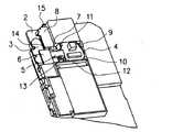
図1及び2は、本実施形態に係るフレキシブルケーブルをフレームに装着した状態を表す図である。本実施形態に係るフレキシブルケーブルは、電子部品等を実装する第1実装部4及び第2実装部8、基板3とフレキシブルケーブル1とを接続するコネクタ部16、コネクタ部16を実装するコネクタ実装部6、柔軟な材料で形成され、コネクタ実装部6から第1実装部4へ情報を伝達するつなぎ部5、及び柔軟な材料で形成され、コネクタ実装部6から第2実装部8へ情報を伝達するつなぎ部7を有している。なお、第1実装部4及び第2実装部8は、フレームを構成する樹脂などの硬い素材の爪(9、10、13、14、15)によって保持される。したがって、第1実装部4及び第2実装部8をその爪に挿入する際に、第1実装部4及び第2実装部8に変形が生じ、実装された部品がフレキシブルケーブルから剥離することがある。または、フレキシブルケーブル1の撓みに耐え切れず、第1実装部4及び第2実装部に実装された部品自体が破損することがある。そこで、本実施形態に係るフレキシブルケーブルの実装構造においては、第1実装部及び第2実装部の必要な範囲に補強板を接着している。もしくは、第1実装部4及び第2実装部8を両面テープなどによりあわせ込み、剛性を上げている。1 and 2 are views showing a state in which the flexible cable according to this embodiment is mounted on a frame. The flexible cable according to the present embodiment includes a
ここで、図4及び5に示すように、つなぎ部5の長手方向の長さは、折り曲げ部17を軸としてコネクタ実装部6の長手方向の長さ以上となっている。よって、折り曲げ部17を軸にフレキシブルケーブルを折り曲げた際、第1実装部4はつなぎ部7と重なり合わず、つなぎ部5のコネクタ実装部6と第1実装部4との中間、又はつなぎ部5の任意の位置に位置する構成とする。フォーミングされた状態で図5のようになり、第1実装部4とコネクタ実装部6を固定した状態で、折り曲げ部17を軸に第2実装部8が回転方向に自由に動かすことが可能となる。 Here, as shown in FIGS. 4 and 5, the length of the connecting
フレーム2には、2つの実装部を保持するための爪(9、10、13、14、15)、又は傾斜構造が形成されている。なお、コネクタ実装部6は、フレーム2に実装された基板3が露出している箇所に配置される。先にも述べたように、このコネクタ実装部6に対し、第1実装部4及び第2実装部8は、縦方向、横方向というように異なる2つの方向に配置されている。 The
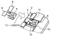
次に、図3から5を用いて、本実施形態に係るフレキシブルケーブルをフレーム2に装着する手順について説明する。 Next, a procedure for attaching the flexible cable according to the present embodiment to the
まず、フレキシブルケーブル1のフレーム2への装着に先立ち、フレキシブルケーブル1上に第1実装部4、第2実装部8、及びコネクタ実装部6に、コネクタ16及び必要な部品を実装する。次に、図4に示す折り曲げ部17を軸にフレキシブルケーブル1を折り曲げることにより、コネクタ実装部6に実装したコネクタ16及び第2実装部8に実装した部品を、第1実装部4に実装した部品の裏面に位置させる。図4のように変形させたフレキシブルケーブル1は、以下に示す手順によりフレーム2へ装着される。 First, prior to mounting the flexible cable 1 on the
次に、図3を用い、フレキシブルケーブル1をフレーム2に装着する手順について説明する。図5に示した形状に折り曲げられたフレキシブルケーブル1は、図3に示す矢印方向に向かってフレーム2に組み込まれる。具体的には、まず、フレキシブルケーブル1をフレーム2に設けられた金型の押し切り又は傾斜構造により形成された爪(9、10)に第1実装部4をスライドさせ、その一部分を挟み込ませ、フレーム2の枠内に収まるよう組み込む。その際、第1実装部4は、爪(9、10)によって挟んだ端部と相対する長手方向の端部を壁(11、12)の高さの範囲内に収める。なお、第1実装部4を挟む爪の数は、実装部の大きさに従い、第1実装部の固定に十分な数だけ設ける。なお、先にも述べたように、フレーム2への組み込みの際に第1実装部4及び第2実装部8が柔軟なケーブル素材のみで構成されていると、実装部品の剥離、部品単体の破壊が生じる。そこで、第1実装部4及び第2実装部8に実装された実装部品の剥離及び実装部品の破壊の防止に十分な強度を確保するため、第1実装部4の裏面に板金材料など硬い材料で作られている補強材を、接着又は両面接着テープなどで固定する。 Next, a procedure for attaching the flexible cable 1 to the
次に、コネクタ実装部6をフレーム2に嵌め込む前に、つなぎ部5の一部をフレーム2の爪13によって挟み、第1実装部4を挟む爪(9、10)と相対するフレキシブルケーブル1の端面の浮きを防止する。その後、コネクタ実装部16をフレーム2から露出した基板3上に実装する。最後に、第2実装部8を爪(14、15)に嵌め込むことにより、フレキシブルケーブル1のフレーム2への組み付けが完了となる。なお、この第2実装部8についても第1実装部4と同様にフレーム2に組み込む際の変形に耐えうる強度を得るために、補強板を第2実装部8の裏面に貼り付ける。 Next, before the
上記の構成によれば、図4及び5に示すように第1実装部4及び第2実装部8を繋ぐフレキシブルケーフル1のつなぎ部(5、7)をフレーム2に装着する際、折り曲げ部17を軸に折り畳み、かつ屈曲させ、2つの実装部がそれぞれ回転方向、長手方向にある一定の範囲にて自由に動かせるため、組み付け時に既に組み込まれた実装部より強制させられる力を軽減できる。そのため、フレーム2の爪(9、10、13、14、15)に無理な力を掛けずにフレキシブルケーブル1をフレーム2に組み込むことができる。また、フレキシブルケーブル1に実装される部品は、フレキシブルケーブル1の一面にのみ実装されるため、両面に実装を行なう場合よりも安価でフレキシブルケーブル1に部品を実装することができる。 According to said structure, when attaching the connection part (5, 7) of the flexible cable 1 which connects the
また、コネクタ実装部6を折り曲げ部17において折り返す構造とした場合、先にフレーム2に組み込まれる第1実装部4及びコネクタ実装部6が固定されることにより、第2実装部8に2方向からの強制力が働き、第2実装部8を爪(14、15)によって挟み込むことができない。また、つなぎ部7が所定の長さより短い場合、爪14に第2実装部が乗っかる形となり、第2実装部8を挟み込めず、爪14が変形する。一方、つなぎ部7の長さが所定の長さより長い場合、爪15に同様の変形が生じる。仮に、爪(14、15)によって第2実装部8を挟み込むことができた場合でも、つなぎ部7が長さ方向に撓むことによりコネクタ実装部6を持ち上げてしまい接続不良を起こす可能性がある。 In addition, when the
しかし、本実施形態に係るフレキシブルケーブルの実装構造によれば、つなぎ部7の長さに一定範囲で誤差が生じても、図6に示すように、折り曲げ部17を中心にコネクタ実装部6と重なり合う範囲で、第2実装部8は回転方向に上下することができる。よって、本構成によれば、つなぎ部7の長さのばらつきによって爪(14、15)、第2実装部8における不良の発生を防止できる。さらに、フレキシブルケーブル1をフレーム2に組み込むときも、折り曲げ部17を中心に回転方向にある一定の自由度をもって動かすことができるため、爪(14、15)の嵌合用傾斜部に同じく回転方向に上下させることにより、フレキシブルケーブル1をフレーム2に容易に実装することができる。 However, according to the flexible cable mounting structure of the present embodiment, even if an error occurs in a certain range in the length of the connecting
なお、本実施形態においては、フレキシブルケーブル1を2次元的に折り曲げてフレーム2に実装した例を説明したが、フレーム2の形状に従い、フレキシブルケーブル1を3次元的に折り曲げて実装することも可能である。 In the present embodiment, the example in which the flexible cable 1 is two-dimensionally bent and mounted on the
さらに、上述のフレキシブルケーブルの実装構造によれば、回路基板等の配置が制限される携帯電話端末やその他の電子回路装置へのフレキシブルケーブルの実装が容易、且つ安価に実現することができる。 Furthermore, according to the above-described flexible cable mounting structure, the flexible cable can be easily and inexpensively mounted on a mobile phone terminal or other electronic circuit device in which the arrangement of a circuit board or the like is limited.
1 フレキシブルケーブル
2 フレーム
3 基板
4 第1実装部
5 つなぎ部
6 コネクタ
7 つなぎ部
8 第2実装部
9、10、13、14、15 爪
11、12 壁
17 折り曲げ部DESCRIPTION OF SYMBOLS 1
Claims (8)
Translated fromJapanese前記第1実装部及びコネクタ実装部を接続する第1のつなぎ部と、
前記第2実装部及びコネクタ実装部を接続する第2のつなぎ部と、を有し、
前記第1,第2実装部及び前記コネクタ実装部が前記コネクタ実装部を中心にしてL字型に並ぶフレキシブルケーブルであって、
前記第1のつなぎ部の前記第1実装部及び前記コネクタ実装部をつなぐ方向に対して略直交する方向にて折曲可能な折り曲げ部を備え、
前記折り曲げ部は、前記第1のつなぎ部が前記折り曲げ部にて折り曲げられた状態のときに前記折り曲げ部を回転起点にする前記第2実装部の回転が可能である程度に変形する柔軟性を有することを特徴とする、
フレキシブルケーブル。A firstmounting portion and aconnector mounting portion capable of mounting electronic components;
Afirst connection portion which connects the firstmounting portion and theconnector mounting portion,
And a secondtether portion for connecting said secondmounting portion and theconnector mounting portion,
The first and second mounting portions and the connector mounting portion are flexible cables arranged in an L shape around the connector mounting portion,
A bending portion that can be bent ina direction substantially orthogonal to a direction connecting the first mounting portion and the connector mounting portion of the first connecting portion;
The bent portion has a flexibility to be deformed to some extent so that the secondmounting portion can be rotated with the bent portion as a rotation starting point when the firstconnecting portion is bent at the bent portion. It is characterized by
Flexible cable.
前記折り曲げ部の幅が前記第1のつなぎ部の幅よりも短いことを特徴とする、請求項1記載のフレキシブルケーブル。When the width of the length in a direction substantially orthogonal to the direction connecting the firstmounting portion and theconnector mounting portion of thefirst connection portion,
The flexible cable according to claim 1, wherein a width of the bent portion is shorter than a width of the firstconnecting portion .
前記電子部品モジュールは、請求項1から4のいずれか1項記載のフレキシブルケーブルに前記電子部品を取り付け、前記折り曲げ部にて前記第1のつなぎ部を折り曲げて得たものであり、
前記第1実装部を前記筐体に組み付ける第1のステップと、
前記折り曲げ部を変形させることによって前記折り曲げ部を回転起点にして前記第2実装部及び前記第2のつなぎ部を回転させつつ前記第2実装部を前記筐体に組み付ける第2のステップと、
を含むことを特徴とする、電子機器の製造方法。A method of manufacturing an electronic device in which an electronic component module is attached to a rigid housing,
The electronic component module is obtained by attaching the electronic component to the flexible cable according to any one of claims 1 to 4, and bending the firstconnecting portion at the bentportion .
A first step of assembling the first mounting portion to the housing;
A second step of assembling the second mounting part to the casing while rotating the second mounting part and the secondconnecting part from the bent part as a rotation starting point by deforming the bent part;
A method for manufacturing an electronic device, comprising:
前記第1のステップは、フレーム形状の前記筐体の第1の部分に前記第1実装部を嵌め込んで前記係止部材により係止することによって前記組み付けがなされ、
前記第2のステップは、フレーム形状の前記筐体の第2の部分に前記回転によって前記第2実装部をスライドさせながら嵌め込んで前記係止部材により係止することによって前記組み付けがなされることを特徴とする、請求項5又は6記載の電子機器の製造方法。The housing has a plurality of locking members for attaching the electronic component module,
In the first step, the assembly is performed by fitting the first mounting portion into the first portion of the frame-shaped casing and locking it by the locking member,
In the second step, the assembly is performed by fitting the second mounting portion into the second portion of the frame-shaped casing while sliding the second mounting portion by the rotation and locking the second mounting portion by the locking member. The manufacturing method of the electronic device of Claim 5 or 6 characterized by these.
Priority Applications (5)
| Application Number | Priority Date | Filing Date | Title |
|---|---|---|---|
| JP2004359728AJP4517845B2 (en) | 2004-12-13 | 2004-12-13 | Flexible cable and method for manufacturing electronic device |
| EP05026607AEP1670296B1 (en) | 2004-12-13 | 2005-12-06 | Flexible circuit board, electronic circuit device, and mobile communication terminal |
| DE602005008691TDE602005008691D1 (en) | 2004-12-13 | 2005-12-06 | Flexible circuit, electronic device and mobile communication terminal |
| CNB2005101302118ACN100539801C (en) | 2004-12-13 | 2005-12-09 | Flexible PCB, electronic circuit apparatus and mobile communication terminal |
| US11/299,816US7551449B2 (en) | 2004-12-13 | 2005-12-13 | Flexible circuit board, electronic circuit device, and mobile communication terminal |
Applications Claiming Priority (1)
| Application Number | Priority Date | Filing Date | Title |
|---|---|---|---|
| JP2004359728AJP4517845B2 (en) | 2004-12-13 | 2004-12-13 | Flexible cable and method for manufacturing electronic device |
Publications (2)
| Publication Number | Publication Date |
|---|---|
| JP2006173176A JP2006173176A (en) | 2006-06-29 |
| JP4517845B2true JP4517845B2 (en) | 2010-08-04 |
Family
ID=36095913
Family Applications (1)
| Application Number | Title | Priority Date | Filing Date |
|---|---|---|---|
| JP2004359728AExpired - Fee RelatedJP4517845B2 (en) | 2004-12-13 | 2004-12-13 | Flexible cable and method for manufacturing electronic device |
Country Status (5)
| Country | Link |
|---|---|
| US (1) | US7551449B2 (en) |
| EP (1) | EP1670296B1 (en) |
| JP (1) | JP4517845B2 (en) |
| CN (1) | CN100539801C (en) |
| DE (1) | DE602005008691D1 (en) |
Families Citing this family (50)
| Publication number | Priority date | Publication date | Assignee | Title |
|---|---|---|---|---|
| US7756553B2 (en) | 2007-01-05 | 2010-07-13 | Apple Inc. | Folded flex assembly for personal media device |
| KR101378880B1 (en)* | 2007-07-13 | 2014-03-28 | 엘지전자 주식회사 | Portable terminal having camera |
| US8097926B2 (en) | 2008-10-07 | 2012-01-17 | Mc10, Inc. | Systems, methods, and devices having stretchable integrated circuitry for sensing and delivering therapy |
| US8389862B2 (en) | 2008-10-07 | 2013-03-05 | Mc10, Inc. | Extremely stretchable electronics |
| JP5646492B2 (en) | 2008-10-07 | 2014-12-24 | エムシー10 インコーポレイテッドMc10,Inc. | Stretchable integrated circuit and device with sensor array |
| US9123614B2 (en) | 2008-10-07 | 2015-09-01 | Mc10, Inc. | Methods and applications of non-planar imaging arrays |
| US9545216B2 (en) | 2011-08-05 | 2017-01-17 | Mc10, Inc. | Catheter balloon methods and apparatus employing sensing elements |
| EP2309829A1 (en)* | 2009-09-24 | 2011-04-13 | Harman Becker Automotive Systems GmbH | Multilayer circuit board |
| WO2011041727A1 (en)* | 2009-10-01 | 2011-04-07 | Mc10, Inc. | Protective cases with integrated electronics |
| CN101877933B (en)* | 2009-12-02 | 2012-06-27 | 友达光电股份有限公司 | Flexible circuit board |
| JP5550326B2 (en)* | 2009-12-18 | 2014-07-16 | キヤノン株式会社 | Electronics |
| JP2014523633A (en) | 2011-05-27 | 2014-09-11 | エムシー10 インコーポレイテッド | Electronic, optical and / or mechanical devices and systems and methods of manufacturing these devices and systems |
| US9757050B2 (en) | 2011-08-05 | 2017-09-12 | Mc10, Inc. | Catheter balloon employing force sensing elements |
| US8611095B2 (en)* | 2011-08-31 | 2013-12-17 | Apple Inc. | Integration of sensors and other electronic components |
| US9226402B2 (en) | 2012-06-11 | 2015-12-29 | Mc10, Inc. | Strain isolation structures for stretchable electronics |
| US9168094B2 (en) | 2012-07-05 | 2015-10-27 | Mc10, Inc. | Catheter device including flow sensing |
| US9295842B2 (en) | 2012-07-05 | 2016-03-29 | Mc10, Inc. | Catheter or guidewire device including flow sensing and use thereof |
| WO2014058473A1 (en) | 2012-10-09 | 2014-04-17 | Mc10, Inc. | Conformal electronics integrated with apparel |
| US9171794B2 (en) | 2012-10-09 | 2015-10-27 | Mc10, Inc. | Embedding thin chips in polymer |
| WO2014171334A1 (en)* | 2013-04-19 | 2014-10-23 | 株式会社村田製作所 | Flexible substrate |
| US9706647B2 (en) | 2013-05-14 | 2017-07-11 | Mc10, Inc. | Conformal electronics including nested serpentine interconnects |
| CA2920485A1 (en) | 2013-08-05 | 2015-02-12 | Mc10, Inc. | Flexible temperature sensor including conformable electronics |
| US9554465B1 (en) | 2013-08-27 | 2017-01-24 | Flextronics Ap, Llc | Stretchable conductor design and methods of making |
| US9674949B1 (en) | 2013-08-27 | 2017-06-06 | Flextronics Ap, Llc | Method of making stretchable interconnect using magnet wires |
| KR20160065948A (en) | 2013-10-07 | 2016-06-09 | 엠씨10, 인크 | Conformal sensor systems for sensing and analysis |
| EP3071096A4 (en) | 2013-11-22 | 2017-08-09 | Mc10, Inc. | Conformal sensor systems for sensing and analysis of cardiac activity |
| US9338915B1 (en) | 2013-12-09 | 2016-05-10 | Flextronics Ap, Llc | Method of attaching electronic module on fabrics by stitching plated through holes |
| US9521748B1 (en) | 2013-12-09 | 2016-12-13 | Multek Technologies, Ltd. | Mechanical measures to limit stress and strain in deformable electronics |
| US9659478B1 (en) | 2013-12-16 | 2017-05-23 | Multek Technologies, Ltd. | Wearable electronic stress and strain indicator |
| CN105874606B (en) | 2014-01-06 | 2021-01-12 | Mc10股份有限公司 | Encapsulated conformal electronic systems and devices and methods of making and using the same |
| US10485118B2 (en) | 2014-03-04 | 2019-11-19 | Mc10, Inc. | Multi-part flexible encapsulation housing for electronic devices and methods of making the same |
| US9723713B1 (en)* | 2014-05-16 | 2017-08-01 | Multek Technologies, Ltd. | Flexible printed circuit board hinge |
| US9899330B2 (en) | 2014-10-03 | 2018-02-20 | Mc10, Inc. | Flexible electronic circuits with embedded integrated circuit die |
| US10297572B2 (en) | 2014-10-06 | 2019-05-21 | Mc10, Inc. | Discrete flexible interconnects for modules of integrated circuits |
| USD781270S1 (en) | 2014-10-15 | 2017-03-14 | Mc10, Inc. | Electronic device having antenna |
| US10440824B2 (en) | 2014-12-31 | 2019-10-08 | Shenzhen Royole Technologies Co., Ltd. | Flexible display device and electronic apparatus |
| WO2016134306A1 (en) | 2015-02-20 | 2016-08-25 | Mc10, Inc. | Automated detection and configuration of wearable devices based on on-body status, location, and/or orientation |
| WO2016140961A1 (en) | 2015-03-02 | 2016-09-09 | Mc10, Inc. | Perspiration sensor |
| WO2017015000A1 (en) | 2015-07-17 | 2017-01-26 | Mc10, Inc. | Conductive stiffener, method of making a conductive stiffener, and conductive adhesive and encapsulation layers |
| US10709384B2 (en) | 2015-08-19 | 2020-07-14 | Mc10, Inc. | Wearable heat flux devices and methods of use |
| EP4079383A3 (en) | 2015-10-01 | 2023-02-22 | Medidata Solutions, Inc. | Method and system for interacting with a virtual environment |
| US10532211B2 (en) | 2015-10-05 | 2020-01-14 | Mc10, Inc. | Method and system for neuromodulation and stimulation |
| US10673280B2 (en) | 2016-02-22 | 2020-06-02 | Mc10, Inc. | System, device, and method for coupled hub and sensor node on-body acquisition of sensor information |
| US10277386B2 (en) | 2016-02-22 | 2019-04-30 | Mc10, Inc. | System, devices, and method for on-body data and power transmission |
| CN105722313B (en)* | 2016-03-24 | 2019-04-05 | Oppo广东移动通信有限公司 | Mobile terminal |
| CN109310340A (en) | 2016-04-19 | 2019-02-05 | Mc10股份有限公司 | Method and system for measuring sweat |
| US10447347B2 (en) | 2016-08-12 | 2019-10-15 | Mc10, Inc. | Wireless charger and high speed data off-loader |
| US10811799B2 (en)* | 2018-02-09 | 2020-10-20 | Metrospec Technology, L.L.C. | Interconnectable circuit boards adapted for lateral in-plane bending |
| CN108696605B (en)* | 2018-03-19 | 2020-04-17 | Oppo广东移动通信有限公司 | Electronic device |
| US12016121B2 (en) | 2020-10-23 | 2024-06-18 | Metrospec Technology, L.L.C. | Interconnectable circuit boards adapted for three-dimensional constructions as lighting sources |
Family Cites Families (31)
| Publication number | Priority date | Publication date | Assignee | Title |
|---|---|---|---|---|
| JPS58306Y2 (en)* | 1975-11-05 | 1983-01-06 | キヤノン株式会社 | printed board structure |
| JPS5868084U (en)* | 1981-10-30 | 1983-05-09 | 株式会社日立製作所 | Stacked electronic unit structure |
| US4845315A (en)* | 1984-05-02 | 1989-07-04 | Mosaic Systems | Cable system |
| BR8502761A (en)* | 1984-06-12 | 1986-02-18 | Luk Lamellen & Kupplungsbau | SET FOR ROTATION SHOCK COMPENSATION |
| US4990948A (en)* | 1986-12-27 | 1991-02-05 | Canon Kabushiki Kaisha | Flexible printed circuit board |
| WO1990006609A1 (en)* | 1988-11-16 | 1990-06-14 | Motorola, Inc. | Flexible substrate electronic assembly |
| JPH0450834U (en)* | 1990-09-04 | 1992-04-28 | ||
| JPH0648321A (en) | 1992-07-27 | 1994-02-22 | Toyota Autom Loom Works Ltd | Opening/closing device for vehicular opening/closing body |
| JP3435245B2 (en)* | 1995-02-21 | 2003-08-11 | ペンタックス株式会社 | Flexible printed wiring board |
| JP3852151B2 (en)* | 1997-03-07 | 2006-11-29 | ソニー株式会社 | Flexible wiring body fixing structure of electronic equipment |
| US6307751B1 (en)* | 1998-06-01 | 2001-10-23 | Wearlogic, Inc. | Flexible circuit assembly |
| JP3066802B1 (en)* | 1998-12-10 | 2000-07-17 | 日本航空電子工業株式会社 | Hinge connector |
| US6494829B1 (en)* | 1999-04-15 | 2002-12-17 | Nexan Limited | Physiological sensor array |
| JP2001024362A (en)* | 1999-07-07 | 2001-01-26 | Sony Corp | Printed wiring film |
| JP2001308260A (en)* | 2000-04-25 | 2001-11-02 | Seiko Epson Corp | Semiconductor device |
| JP2001358422A (en) | 2000-06-13 | 2001-12-26 | Sony Corp | Electronic circuit device |
| JP2002217570A (en)* | 2001-01-22 | 2002-08-02 | Matsushita Electric Ind Co Ltd | Board mounting method and portable equipment |
| JP2002223086A (en)* | 2001-01-25 | 2002-08-09 | Matsushita Electric Ind Co Ltd | Circuit connection method, circuit forming body, and portable terminal |
| JP3988109B2 (en)* | 2001-03-08 | 2007-10-10 | フジノン株式会社 | Connection structure for flexible boards installed in the camera |
| JP2002321423A (en)* | 2001-04-26 | 2002-11-05 | Brother Ind Ltd | Recording device |
| WO2002087887A1 (en)* | 2001-04-26 | 2002-11-07 | Brother Kogyo Kabushiki Kaisha | Recording head unit, manufacturing method thereof, and recorder using the unit |
| JP2002321344A (en)* | 2001-04-26 | 2002-11-05 | Brother Ind Ltd | Recording head unit |
| JP2002368440A (en)* | 2001-06-06 | 2002-12-20 | Toshiba Corp | Foldable electronic devices and their flexible substrates |
| EP1396835A4 (en)* | 2001-06-15 | 2008-04-16 | Matsushita Electric Industrial Co Ltd | PLASMA DISPLAY |
| US6950312B2 (en)* | 2001-10-02 | 2005-09-27 | International Business Machines Corporation | Electronic units and method for packaging and assembly of said electronic units |
| JP3952897B2 (en) | 2002-07-31 | 2007-08-01 | 日本電気株式会社 | Camera module and portable communication terminal using the same |
| US7071547B2 (en)* | 2002-09-11 | 2006-07-04 | Tessera, Inc. | Assemblies having stacked semiconductor chips and methods of making same |
| JP2004153670A (en)* | 2002-10-31 | 2004-05-27 | Sharp Corp | Portable equipment |
| JP2004335042A (en)* | 2003-05-12 | 2004-11-25 | Hitachi Global Storage Technologies Inc | Head support mechanism and magnetic disk drive |
| JP4144436B2 (en)* | 2003-06-02 | 2008-09-03 | セイコーエプソン株式会社 | Electro-optic module and electronic device |
| TWI231740B (en)* | 2004-05-20 | 2005-04-21 | Au Optronics Corp | Display module and locating method of flexible print circuit board thereof |
- 2004
- 2004-12-13JPJP2004359728Apatent/JP4517845B2/ennot_activeExpired - Fee Related
- 2005
- 2005-12-06EPEP05026607Apatent/EP1670296B1/ennot_activeNot-in-force
- 2005-12-06DEDE602005008691Tpatent/DE602005008691D1/enactiveActive
- 2005-12-09CNCNB2005101302118Apatent/CN100539801C/ennot_activeExpired - Fee Related
- 2005-12-13USUS11/299,816patent/US7551449B2/ennot_activeExpired - Fee Related
Also Published As
| Publication number | Publication date |
|---|---|
| JP2006173176A (en) | 2006-06-29 |
| EP1670296B1 (en) | 2008-08-06 |
| US7551449B2 (en) | 2009-06-23 |
| CN1791301A (en) | 2006-06-21 |
| EP1670296A1 (en) | 2006-06-14 |
| US20060128346A1 (en) | 2006-06-15 |
| DE602005008691D1 (en) | 2008-09-18 |
| CN100539801C (en) | 2009-09-09 |
Similar Documents
| Publication | Publication Date | Title |
|---|---|---|
| JP4517845B2 (en) | Flexible cable and method for manufacturing electronic device | |
| JP4413956B2 (en) | Camera module and portable terminal | |
| EP2023607A2 (en) | Vehicle camera system | |
| JP2007243550A (en) | Electronic apparatus | |
| JP2003133764A (en) | Biaxial hinge device | |
| KR20140048672A (en) | Connecting device for electronic components of portable terminal | |
| JP2007215017A (en) | Electronic equipment with camera | |
| JP3963386B2 (en) | Double-sided connector | |
| JP5168119B2 (en) | Camera phone | |
| JP2944641B1 (en) | Electronic device holding equipment | |
| EP3285117B1 (en) | Circuit board assembly and terminal | |
| JP2008108453A (en) | socket | |
| JP4094581B2 (en) | Connection structure between printed circuit board and hinge unit in foldable portable terminal and connection member thereof | |
| JP4569903B2 (en) | FPC mounting structure and folding electronic device | |
| JP5062537B2 (en) | Camera module and portable terminal | |
| TWI793957B (en) | Lens module and terminal device | |
| CN105556388B (en) | Camera module | |
| JP4094580B2 (en) | FPC holding member and folding electronic device using the same | |
| CN223231373U (en) | Circuit board assemblies and electronic devices | |
| JP4338535B2 (en) | Electronic device having flexible wiring member | |
| JP4454601B2 (en) | Flexible cable fixing structure | |
| JP2013106259A (en) | Portable terminal | |
| JP2012244052A (en) | Component fixation structure and portable electronic apparatus including the same | |
| JPH1154873A (en) | Flexible printed circuit board | |
| KR20110129204A (en) | Camera module and manufacturing method thereof |
Legal Events
| Date | Code | Title | Description |
|---|---|---|---|
| A621 | Written request for application examination | Free format text:JAPANESE INTERMEDIATE CODE: A621 Effective date:20071112 | |
| A131 | Notification of reasons for refusal | Free format text:JAPANESE INTERMEDIATE CODE: A131 Effective date:20091027 | |
| A521 | Request for written amendment filed | Free format text:JAPANESE INTERMEDIATE CODE: A523 Effective date:20091228 | |
| A131 | Notification of reasons for refusal | Free format text:JAPANESE INTERMEDIATE CODE: A131 Effective date:20100202 | |
| A521 | Request for written amendment filed | Free format text:JAPANESE INTERMEDIATE CODE: A523 Effective date:20100402 | |
| TRDD | Decision of grant or rejection written | ||
| A01 | Written decision to grant a patent or to grant a registration (utility model) | Free format text:JAPANESE INTERMEDIATE CODE: A01 Effective date:20100427 | |
| A01 | Written decision to grant a patent or to grant a registration (utility model) | Free format text:JAPANESE INTERMEDIATE CODE: A01 | |
| A61 | First payment of annual fees (during grant procedure) | Free format text:JAPANESE INTERMEDIATE CODE: A61 Effective date:20100510 | |
| FPAY | Renewal fee payment (event date is renewal date of database) | Free format text:PAYMENT UNTIL: 20130528 Year of fee payment:3 | |
| R150 | Certificate of patent or registration of utility model | Free format text:JAPANESE INTERMEDIATE CODE: R150 | |
| LAPS | Cancellation because of no payment of annual fees |