JP4517578B2 - Peer-to-peer communication apparatus and communication method - Google Patents
Peer-to-peer communication apparatus and communication methodDownload PDFInfo
- Publication number
- JP4517578B2 JP4517578B2JP2003064328AJP2003064328AJP4517578B2JP 4517578 B2JP4517578 B2JP 4517578B2JP 2003064328 AJP2003064328 AJP 2003064328AJP 2003064328 AJP2003064328 AJP 2003064328AJP 4517578 B2JP4517578 B2JP 4517578B2
- Authority
- JP
- Japan
- Prior art keywords
- communication
- security policy
- peer
- communication device
- presence information
- Prior art date
- Legal status (The legal status is an assumption and is not a legal conclusion. Google has not performed a legal analysis and makes no representation as to the accuracy of the status listed.)
- Expired - Fee Related
Links
Images


Classifications
- H—ELECTRICITY
- H04—ELECTRIC COMMUNICATION TECHNIQUE
- H04L—TRANSMISSION OF DIGITAL INFORMATION, e.g. TELEGRAPHIC COMMUNICATION
- H04L63/00—Network architectures or network communication protocols for network security
- H04L63/16—Implementing security features at a particular protocol layer
- H04L63/164—Implementing security features at a particular protocol layer at the network layer
- H—ELECTRICITY
- H04—ELECTRIC COMMUNICATION TECHNIQUE
- H04L—TRANSMISSION OF DIGITAL INFORMATION, e.g. TELEGRAPHIC COMMUNICATION
- H04L63/00—Network architectures or network communication protocols for network security
- H04L63/20—Network architectures or network communication protocols for network security for managing network security; network security policies in general
- H—ELECTRICITY
- H04—ELECTRIC COMMUNICATION TECHNIQUE
- H04W—WIRELESS COMMUNICATION NETWORKS
- H04W4/00—Services specially adapted for wireless communication networks; Facilities therefor
- H04W4/02—Services making use of location information
- H—ELECTRICITY
- H04—ELECTRIC COMMUNICATION TECHNIQUE
- H04L—TRANSMISSION OF DIGITAL INFORMATION, e.g. TELEGRAPHIC COMMUNICATION
- H04L63/00—Network architectures or network communication protocols for network security
- H04L63/10—Network architectures or network communication protocols for network security for controlling access to devices or network resources
- H04L63/104—Grouping of entities
- H—ELECTRICITY
- H04—ELECTRIC COMMUNICATION TECHNIQUE
- H04L—TRANSMISSION OF DIGITAL INFORMATION, e.g. TELEGRAPHIC COMMUNICATION
- H04L67/00—Network arrangements or protocols for supporting network services or applications
- H04L67/50—Network services
- H04L67/52—Network services specially adapted for the location of the user terminal
- H—ELECTRICITY
- H04—ELECTRIC COMMUNICATION TECHNIQUE
- H04L—TRANSMISSION OF DIGITAL INFORMATION, e.g. TELEGRAPHIC COMMUNICATION
- H04L67/00—Network arrangements or protocols for supporting network services or applications
- H04L67/50—Network services
- H04L67/54—Presence management, e.g. monitoring or registration for receipt of user log-on information, or the connection status of the users
- H—ELECTRICITY
- H04—ELECTRIC COMMUNICATION TECHNIQUE
- H04W—WIRELESS COMMUNICATION NETWORKS
- H04W4/00—Services specially adapted for wireless communication networks; Facilities therefor
- H04W4/02—Services making use of location information
- H04W4/029—Location-based management or tracking services
Landscapes
- Engineering & Computer Science (AREA)
- Computer Security & Cryptography (AREA)
- Computer Networks & Wireless Communication (AREA)
- Signal Processing (AREA)
- Computer Hardware Design (AREA)
- Computing Systems (AREA)
- General Engineering & Computer Science (AREA)
- Data Exchanges In Wide-Area Networks (AREA)
- Computer And Data Communications (AREA)
- Information Transfer Between Computers (AREA)
Description
Translated fromJapanese【0001】
【発明の属する技術分野】
本発明は、1対1の対等型ピアツーピア通信装置に関し、特に、通信相手や通信相手のネットワーク状況に応じた最適な通信セキュリティ規則を適用するピアツーピア通信装置に関する。
【0002】
【従来の技術】
インターネット電話を代表とするピアツーピア通信において、第三者によって通信内容を盗聴または改竄されることを防ぐために、通信パケットの暗号化や認証が行われる。通信パケットの暗号化や認証は、個々の通信パケットに対してどのような暗号化や認証を行うかといった一連の規則であるセキュリティポリシに従って行われる。なお、このようなセキュリティポリシを格納するデータベースをセキュリティポリシデータベースといい、通常、別途設置されたポリシーサーバと呼ばれる装置に格納されている。
【0003】
インターネット技術の標準化組織であるIETFでは、インターネットにおけるIP (Internet Protocol)パケットレベルでのセキュリティ(第三者による通信内容の盗聴や改竄等の防止)を確保するプロトコルとしてIPsec(IP security)を策定している(非特許文献1参照)。
【0004】
これによれば、送信元および送信先のIPアドレスとポート番号、TCP(Transmission Control Protocol)やUDP(User Datagram Protocol)といった上位層プロトコルの種別、受信パケットか送信パケットかを示す通信の方向といった情報を用いて、当該ピアツーピア通信に適用すべきセキュリティポリシを選択する。
【0005】
そして、選択したセキュリティポリシに記述されているセキュリティ要件(パケットを破棄するかしないか、暗号化を行うか認証を行うか、必ず行うか可能な場合のみ行うか等)が適用される。すなわち、送信側の装置は、送信するパケットの送信元アドレスや送信先アドレスから、セキュリティポリシデータベースを検索し、該当するセキュリティポリシにて示されるセキュリティ要件を満たす暗号化や認証処理を行った後、通信相手にパケットを送信する。
【0006】
同様に、受信側の装置は、受信したパケットの送信元アドレスや送信先アドレスから、セキュリティポリシデータベースを検索し、受信パケットが該当するセキュリティポリシにて示されるセキュリティ要件を満たす暗号化や認証処理が行われているかを検査し、セキュリティ要件を満たしていないパケットは上位層に渡すことなく廃棄する。
【0007】
インターネットを用いて、2つの通信ノード間で仮想的な専用線を確立するVPN(Virtual Private Network)において、IPsecを用いて通信のセキュリティを確保する技術としては、例えば、非特許文献2に開示されているものがある。
【0008】
【非特許文献1】
IETF RFC 2401、1998年11月25日、p.14−17
【非特許文献2】
石井貴之、他1名、「透過的で動的なVPNメカニズムを実現」、季刊IPv6マガジン、株式会社インプレス、平成14年8月18日、Summer 2002 NO.2、p.74−75
【0009】
【発明が解決しようとする課題】
上記非特許文献1に記載のIPsecを適用したピアツーピア通信では、送信側装置に登録されているセキュリティポリシのセキュリティ要件が、受信側装置に登録されている要件を満たさない場合、送信側装置が送信したパケットは受信側装置にて受信後廃棄される。従って、相手装置と適切に通信を行うためには、予め通信装置間において互いのセキュリティポリシを交渉または交換し、通信相手装置のセキュリティ要件を満たすセキュリティポリシに基づいて通信を行う必要がある。
【0010】
また、モバイル端末装置によるピアツーピア通信のように、通信相手装置が同一の場合であったとしても、それが社内ネットワークに接続されている場合には相応のセキュリティが確保済みと考えられるため、セキュリティレベルを落としたセキュリティポリシを用いて暗号処理等を必要としないより軽快な通信を行い、通信相手端末が社外ネットワークに接続されている場合には、よりセキュリティレベルの高いセキュリティポリシを用いた通信が望まれる。
【0011】
さらに、通信相手が家族や友人・知人かそうでないか、通信内容がビジネスかプライベートか、また単なる宣伝・広告か等により、適切なセキュリティレベルによる通信が期待できる。
【0012】
しかしながら、通信相手が上述のような各種状況に応じて適切なセキュリティポリシを作成し設定しているとは限らない。例えば、社内ネットワークに接続されたモバイル端末装置が移動し、接続先が社外ネットワークに切り替えられた際、セキュリティポリシが従前の社内ネットワークに適した比較的緩いセキュリティ要件のままであった場合、第3者等によって通信パケットを盗聴や改竄される危険性が高くなる。
【0013】
一方、非特許文献2に記載の技術では、ネットワーク上に設けた外部のIPsec通信管理サーバを介して、通信装置相互間でセキュリティポリシ情報の送受信、およびネゴシエーションを行っている。
【0014】
しかしながら、外部に設置したサーバを用いているため、サーバにてネットワーク上の通信セキュリティポリシを集中的に管理し,通信装置がセキュリティポリシの変更を行えないという問題があり、利用者が通信状況に応じてセキュリティポリシを自由に設定するといった柔軟的な機能を提供することは不可能であった。
【0015】
本発明では、通信パケットに対する暗号および認証規則を示す情報であるセキュリティポリシと、通信端末の接続ネットワークの情報や通信相手の情報および通信内容の情報といった通信端末の状態を示す情報であるプレゼンス情報とを、通信装置間で互いに交換し、通信状況に応じた適切なセキュリティポリシによって、通信の安全性が確保されたピアツーピア通信を可能とする通信装置を提供することを課題とする。
【0016】
さらに、利用者が通信状況に応じてセキュリティポリシを自由に設定することを可能とする通信装置を提供することを課題とする。
【0017】
【課題を解決するための手段】
上記課題を解決するために本発明では、IPネットワークに接続された他の通信装置が属するネットワークおよび前記他の通信装置の利用者に関するプレゼンス情報を取得する手段と、前記他の通信装置の通信パケットの送受信における一連の暗号および認証規則を示すセキュリティポリシ情報を取得する手段とを備え、前記プレゼンス情報と前記セキュリティポリシ情報とから、前記他の通信装置に送信するIPパケットのセキュリティポリシを決定し、前記決定したセキュリティポリシを用いて前記他の通信装置にIPパケットを送信するようにした。
【0018】
また、前記取得したプレゼンス情報と前記取得したセキュリティポリシ情報とから新たに決定した送信IPパケットのセキュリティポリシ情報を、前記他の通信装置に通知する構成とした。
【0019】
さらに、前記取得したプレゼンス情報と前記取得したセキュリティポリシ情報とを表示し、前記新たに決定したセキュリティポリシ情報を入力するために周辺機器との外部インタフェースをさらに設けた。
【0020】
【発明の実施の形態】
以下、本発明の実施形態について説明する。ここでは、通信網としてIPネットワークを用い、通信の安全性を確保するプロトコルとしてIPsecを用いた場合を例として説明する。
【0021】
図1は本発明の通信装置10の内部構成を説明する図である。本通信装置10はIPネットワーク1を介して通信相手装置11と通信を行う。なお、図1の通信装置10は、以下に説明するセキュリティポリシの設定等に係る機能ブロックを中心に示したものであり、実際には、モバイル用PCやIP電話といった通信装置の種別によって異なる、他の図示しない機能ブロックを有している。また、通信相手装置11も本通信装置10と同一の機能構成を有するものとする。
【0022】
本発明の通信装置10は、IP機能ブロック100、IPsec機能ブロック110、ピアツーピア通信機能ブロック200、セキュリティポリシデータベース300、セキュリティポリシ処理部301、セキュリティポリシ入出力I/F302、プレゼンス情報データベース400、プレゼンス情報処理部401、プレゼンス情報入出力I/F402、セキュリティポリシプレゼンス情報要求指示I/F403から構成される。
【0023】
IP機能ブロック100はデータパケットの送受信インタフェースであり、IPパケットの終端および生成を行う。IPsec機能ブロック110はIPレイヤでのセキュリティを確保する機能ブロックであり、IPパケットに対する認証および暗号化を行う。ピアツーピア通信機能ブロック200はピアツーピア通信を実現する機能ブロックであり、通信装置間でのピアツーピア通信セッションの確立、確立したセッション上でのピアツーピア通信、および確立セッションの切断を行う。
【0024】
セキュリティポリシデータベース300は通信端末のセキュリティポリシを格納したデータベースであり、IPsec機能ブロックにて適用するセキュリティポリシの管理を行う。セキュリティポリシ処理部301はセキュリティポリシデータベースへのアクセスを行う機能ブロックであり、セキュリティポリシデータベースへのセキュリティポリシの登録や削除、ならびに参照を行う。セキュリティポリシ入出力インタフェース302はセキュリティポリシデータベースへのアクセスのためのユーザインタフェースであり、利用者に対し通信装置のセキュリティポリシデータベースへのアクセスを提供する。
【0025】
セキュリティポリシプレゼンス情報要求指示インタフェース403はセキュリティポリシおよびプレゼンス情報の取得要求を行うためのユーザインタフェースであり、周辺機器20等を介して、利用者に対し通信相手装置のセキュリティポリシやプレゼンス情報の取得要求を可能とする。プレゼンス情報データベース400は通信端末のプレゼンス情報を格納したデータベースであり、通信装置のプレゼンス情報の管理を行う。
【0026】
プレゼンス情報処理部401はプレゼンス情報データベースへのアクセスを行う機能ブロックであり、プレゼンス情報データベースへのプレゼンス情報の登録削除や参照を行う。プレゼンス情報入出力インタフェース402はプレゼンス情報データベースへのアクセスのためのユーザインタフェースであり、利用者に対し通信装置のプレゼンス情報データベースへのアクセス機能の提供を行う。
【0027】
なお、上記のセキュリティポリシ入出力インタフェース302、セキュリティポリシプレゼンス情報要求指示インタフェース403およびプレゼンス情報入出力インタフェース402は、外部に別途用意されたディスプレイ装置、キーボード、マウス等の周辺機器20に接続され、例えば、キーボードやマウス等を用いて各種情報の入力を行ったり、ディスプレイ装置を用いて出力情報の表示を行うことができる。
【0028】
図2は通信装置10が適用されるネットワーク構成を示す図である。ここでは、利用者9が通信装置10を用い、社内ネットワーク2を介して通信相手装置A11−1とピアツーピア通信を行う場合と、社内ネットワーク2およびインターネット3を介して通信相手装置B11−2とピアツーピア通信を行う場合とを示している。
【0029】
なお、通信装置10および通信相手装置A11−1のIPアドレスとしては、インターネットの標準化組織であるIETFにて制定されたRFC1597に規定されたクラスCのプライベートアドレスを想定し、それぞれ192.168.1.1および192.168.1.2とする。また、通信相手装置B11−2のIPアドレスとしては、133.134.10.10として説明を行う。なお、以上のIPアドレスの値はあくまでも一例であり、他のアドレスであっても問題ない。
【0030】
以下、図3〜図9を用いて通信相手装置A11−1との通信方法を説明し、図10〜図13を用いて通信相手装置B11−2との通信方法を説明する。
【0031】
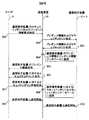
まず、社内ネットワーク2のみを介した通信装置10と通信相手装置A11−1との通信方法を説明する。図3は、利用者9が通信装置10を用いて通信相手装置A11−1とピアツーピア通信を開始する際のメッセージシーケンスである。
【0032】
利用者9は、まず通信装置10に対し、図1に示す周辺機器20からセキュリティポリシプレゼンス情報要求指示I/F403を介して、通信相手装置A11−1のセキュリティポリシおよびプレゼンス情報の取得を指示する501。指示を受けた通信装置10は、通信相手装置A11−1にプレゼンス情報およびセキュリティポリシを要求するメッセージをピアツーピア通信機能ブロック200にて生成し、IP機能ブロック100を介してIPパケットに載せて送信する502。
【0033】
本パケットは通常のデータパケットと異なり、セキュリティポリシを交換するためのパケットであり、例えばInternet−Draft(draft−IETF−impp−cpim−pidf−07.txt)で規定されたフォーマットで生成されている。したがって、このIPパケットが受信側の通信相手装置A11−1のセキュリティポリシを満たしているかは不明であるが、この段階では受信側装置で廃棄されることなく受信される。
【0034】
本要求メッセージを受信した通信相手装置A11−1は、プレゼンス情報およびセキュリティポリシを応答メッセージとしてIPパケットに載せて返信する503。通信装置10は上記通信相手装置A11−1からの応答メッセージが載せられたIPパケットを受信すると、プレゼンス情報処理部401にて受信パケットの内容を解析することによって、相手通信装置A11−1のプレゼンス情報を抽出し、プレゼンス情報データベース400に登録する504。そしてプレゼンス情報入出力I/F402から周辺機器20を用いて、通信相手装置A11aのプレゼンス情報を利用者9に対して表示する505。
【0035】
同様に、通信相手装置A11−1からの応答パケットをセキュリティポリシ処理部301にて解析することによって通信相手装置A11−1のセキュリティポリシデータを抽出し、セキュリティポリシ入出力I/F302から周辺機器20を用い当該セキュリティポリシを利用者9に対して表示する506。
【0036】
利用者9は、表示された通信相手装置A11−1における通信装置10に対するセキュリティポリシの内容を検討し必要に応じて変更する。例えば、セキュリティレベルをより高く変更したり、あるいは低くする等を行う。
【0037】
前記のように内容が見直されたセキュリティポリシは、セキュリティポリシ入出力I/F302から周辺機器20を用い登録される507。登録の指示を受けた通信装置10は、上記の通信相手装置Aに対するセキュリティポリシを、セキュリティポリシ処理部301を介してセキュリティポリシデータベース300に登録する508。
【0038】
その後、利用者9はピアツーピア通信機能ブロック200を介して通信相手装置A11−1とのピアツーピア通信の開始を指示し509、指示を受けた通信装置10は、前記ピアツーピア通信機能ブロック200を用いて通信相手装置A11−1とのピアツーピア通信を開始する510。
【0039】
ピアツーピア通信機能ブロック200には、周辺機器あるいは図示しない外部の装置や端末等から、通信相手装置に向けた通常の通信データが入力され、IPsec機能ブロックとの間で、相手装置との送受信データのIPアドレスやポート番号、上位プロトコルの種別を受渡しすることによって、セキュリティポリシデータベース300に登録された前記セキュリティポリシに基づいたデータパケットが生成される。
【0040】
図4は、図3のシーケンスにおける通信相手装置A11−1のセキュリティポリシおよびプレゼンス情報要求指示時501にて、セキュリティポリシプレゼンス情報要求指示I/F403が周辺機器20のディスプレイ装置等に提供するGUI(グラフィカルユーザインタフェース)410の一例である。通信相手装置のアドレスをテキストボックス411に入力し、要求する情報のチェックボックス412、413をチェックし、OKボタン414を押すことで要求を指示する。
【0041】
図5に、図3のシーケンスにおける、通信相手装置A11−1からのプレゼンス情報およびセキュリティポリシ情報の応答503におけるプレゼンス情報およびセキュリティポリシの記述部分の一例を示す。ここでは、IETF(Internet Engineering Task Force)のIMPP(Instant Messaging and Presence Protocol) WG(Working Group)にて作成中であるPIDF(Presence Information Date Format)に準拠したフォーマットで作成されている。
【0042】
図5において、520〜526がセキュリティポリシに関する情報であり、527〜528がプレゼンス情報である。なお、本メッセージは、例えばIETFのRFC(Request for Comments)3261に規定されたSIPに代表されるピアツーピア通信プロトコルを用いて送受信が可能である。
【0043】
図6は、図3のシーケンスにおいて通信相手装置A11−1のプレゼンス情報をプレゼンス情報データベース400に登録した時504における、プレゼンス情報データベース400の内容の一例である。各要素は、関連する通信装置のプレゼンス情報に対応し、端末の識別情報であるentity620、端末のアドレス621、端末の現在の利用者名622、端末のある場所623、本プレゼンス情報が作成された日時624の各行から構成される。ここでは、625および627〜629がそれぞれ図5のメッセージの530および527〜529に対応する。
【0044】
図7は、図3のシーケンスにおいて通信相手装置A11−1に対するセキュリティポリシをセキュリティポリシデータベース300に登録した時508のセキュリティポリシデータベース300内容の一例である。各要素は通信相手装置11に対するセキュリティポリシに対応し、送信元のアドレス710とそのポート番号711、送信先のアドレス712とそのポート番号713、トランスポート層のプロトコル714、送信か受信かを示す方向715、パケットに対してどのような処理を行うかを示すアクション716がある。
【0045】
また、アクションにてipsecを指定した場合についてはさらに、プロトコル717、モード718、エンドポイント719、レベル720の各行から構成される。ここでは、721〜727がそれぞれ図5のメッセージの510〜516に対応する。
【0046】
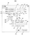
図8に、前記通信相手装置A11−1との間のセキュリティポリシを表示した時506における、セキュリティポリシ入出力I/F302が周辺機器20のディスプレイ装置等に提供するGUI800の一例を示す。送信元および送信先のアドレスは、それぞれテキストボックス810および814に表示される。
【0047】
特定のポートが指定されている場合は、テキストボックスのチェックボックス811および815が選択され、テキストボックス812および816に具体的なポート番号が表示される。特定のポートが指定されていない場合にはanyのチェックボックス813および817が選択される。
【0048】
トランスポート層のプロトコルは、対応するプロトコル名のラジオボタン818または819が選択される。プロトコルが指定されていない場合はanyのラジオボタン820が選択される。パケットの送信方向は、受信パケットならばinのラジオボタン821が選択され、送信方向ならばoutのラジオボタン822が選択される。
【0049】
パケットに対する処理については、パケット廃棄処理を行うならばdiscardのラジオボタン823が選択され、何も処理を行わないのであればnoneのラジオボタン824が選択され、ipsec処理を行うならばipsecのラジオボタン825が選択される。
【0050】
ipsecのラジオボタンが選択されている場合には、さらに、適用するセキュリティプロトコルであるah(認証)826、esp(暗号)827、ipcomp(圧縮)828のそれぞれのチェックボックスが選択される。適用するモードがトランスポートモードかトンネルモードかはラジオボタン829または830を選択する。トンネルモードの場合は、トンネルのもう一方の端となる装置を示すテキストボックス831が表示され、セキュリティレベルとしてdefault(デフォルト)832、use(可能ならば)833、require(必須)834のそれぞれのラジオボタンが表示される。
【0051】
図8では、通信相手装置A11−1から受け取ったセキュリティポリシを元に、通信相手装置A11−1に対するセキュリティポリシとして、送信元アドレス192.168.1.1、ポートany、送信先アドレス192.168.1.2、ポートany、トランスポートudp、方向out、アクションnoneがそれぞれ選択され、表示されている。通信相手装置A11−1は社内IPネットワークに接続されているので、利用者はセキュリティポリシの変更は不要と判断し、このままのセキュリティポリシで登録ボタン835を押し、セキュリティポリシデータベースに登録を行う。
【0052】
図9に前記通信相手装置A11−1のプレゼンス情報を表示した時505における、プレゼンス情報入出力I/F402が周辺機器のディスプレイ装置等に提供するGUI900の一例を示す。
【0053】
端末の識別情報であるentity910、端末のアドレス911、端末の現在の利用者912、端末のある場所913、プレゼンス情報が作成された日時914がそれぞれ表示される。図9では、通信相手装置Aから受け取ったプレゼンス情報として、entity peerA@example.com917、アドレス192.168.1.2(918)、利用者John919、場所office920、日時2002−09−28 10:49:29(921)がそれぞれ表示されている。したがって、通信装置の利用者は、通信装置A11−1が社内IPネットワークに接続されていることを知ることができる。
【0054】
なお、通信相手装置A11−1のプレゼンス情報はプレゼンス情報要求時にプレゼンス情報データベースに登録される。利用者はプレゼンス情報入出力I/Fを用いて、通信相手装置A11−1のプレゼンス情報のうち、利用者と場所の欄のみ利用者の好みに応じて親しみやすい値等に変更することが出来る。
【0055】
次に、社内IPネットワーク2とインターネット3とを介した通信装置10と通信相手装置B11−2との通信方法を説明する。図10は、利用者9が通信装置10を用いて通信相手装置B11−2とピアツーピア通信を開始する際のメッセージシーケンスである。利用者9は、前述の通信装置A11−1と通信を行う場合と同様、通信装置10に対し前記セキュリティポリシプレゼンス情報要求指示I/F403が周辺機器20のディスプレイ装置等に提供するGUI等を用いて、通信相手装置B11−2のセキュリティポリシおよびプレゼンス情報の要求を指示する601。
【0056】
指示を受けた通信装置10は、通信相手装置B11−2にプレゼンス情報およびセキュリティポリシを要求するメッセージを送信する602。通信相手装置B11−2はプレゼンス情報およびセキュリティポリシを応答するメッセージを返信する603。
【0057】
応答メッセージを受信した通信装置10は、通信相手装置B11−2のプレゼンス情報を前記プレゼンス情報データベース400に登録し604、前記プレゼンス情報入出力I/F402を用いて周辺機器20のディスプレイ装置等に通信相手装置B11−2のプレゼンス情報を表示する605。また、前記セキュリティポリシ入出力I/F302を用いて周辺機器20のディスプレイ装置等に通信相手装置B11−2との間のセキュリティポリシを表示する606。以上は前述の図3に示した社内IPネットワーク2を介した通信相手装置A11−1とのメッセージシーケンスと同一である。
【0058】
ここで、利用者9は表示された通信相手装置B11−2のプレゼンス情報を解析することによって、通信相手装置B11−2の現状の接続先が社外のネットワークであることが分かる。
【0059】
図11は、図10のシーケンスにおいて前記通信相手装置Bのプレゼンス情報を表示した時605の、外部のディスプレイ装置へのGUI110の一例である。場所930がstationとなっており、通信相手装置B11−2が社外ネットワークに接続されていることが判る。そこで、別途表示された通信相手装置B11−2との間のセキュリティポリシの内容を解析し、セキュリティレベルが現状に相応なものか否かを判断する。
【0060】
図12は、このときのセキュリティポリシの外部ディスプレイ装置へのGUI1200の一例である。通信パケットに対する処理がnone850となっているため、通信パケットに対するセキュリティ処理を行わないポリシであることを示している。なお、これは図8に示した社内IPネットワークのみを介した通信を前提としたセキュリティポリシと同等である。
【0061】
このような場合、通信の安全性を確保するためのセキュリティポリシとしては十分でないと判断し、図10のシーケンス608に示すように、利用者9は通信相手装置B11−2に対するセキュリティポリシをレベルのより高いものに変更する。そして利用者9は通信装置10に対して、その変更後のセキュリティポリシの登録を指示し609、指示を受けた通信装置10は、前記セキュリティポリシデータベース300に登録する610。
【0062】
図13はこの変更時における、セキュリティポリシの外部ディスプレイ装置へのGUI1300の一例である。すなわち、先の図11が変更前、本図13が変更後に相当するものである。通信相手装置B11−2のプレゼンス情報から通信相手装置B11−2が社外ネットワークに接続していることが明らかとなったため、通信相手装置B11−2への送信パケットに対して、セキュリティ処理(ipsec860)を行うこととし、認証(ah861)、暗号化(esp862)を必須(require865)としていることを示している。
【0063】
その後、利用者9は通信相手装置B11−2とのピアツーピア通信の開始を指示し611、指示を受けた通信装置10は、前記ピアツーピア通信機能ブロック200を用いて通信相手装置B11−2とのピアツーピア通信を開始する612。
【0064】
ここで、通信相手装置B11−2が保持している通信装置10からの受信パケットに関するセキュリティポリシ(SP1)と、通信装置10が保持している通信相手装置B11−2への送信パケットに関するセキュリティポリシ(SP2)とを比較すると、SP1に比べてSP2の方がそのセキュリティレベルが高いものとなっている。
【0065】
しかしながら、受信側(通信相手装置B11−2)で設定している以上のセキュリティレベルで送信されたパケットについては、受信側でそのまま受信してもセキュリティ上の問題はない。したがって、通信に先立って通信装置10から通信相手装置B11−2に対してセキュリティポリシの変更やそのネゴシエーションを実施することは必ずしも必要でない。
【0066】
これに対して、前述のセキュリティポリシの変更時608において、変更後のセキュリティポリシのセキュリティレベルが通信相手装置B11−2にて保持するものと比して低くなるよう変更した場合、通信相手装置B11−2では自ら設定しているより低いセキュリティレベルの受信パケットは廃棄等の処理が行われるため、通信装置10は通信に先立って通信相手装置B11−2とセキュリティポリシの変更に関してネゴシエーションが必要となる。
【0067】
なお、以上の実施例では、セキュリティ通信プロトコルとしてIPsecを前提として説明を行ったが、IPsec機能ブロックを置き換えることによって、他のセキュリティ通信プロトコルにも適用可能である。また、セキュリティポリシデータベースやプレゼンス情報データベースは必ずしもデータベースである必要はなく、メモリ上のテーブルでも実現可能である。
【0068】
【発明の効果】
以上のように本発明によれば、ピアツーピア通信において通信端末や使用者の状況に応じた適切なセキュリティポリシを用いた通信が可能となる。また、適切なセキュリティポリシを選択可能とすることにより、過剰なセキュリティレベルでのピアツーピア通信を防ぎ、通信端末でのCPUリソースや通信ネットワークの帯域の節約が可能となる。
【図面の簡単な説明】
【図1】本発明の通信装置の内部ブロック図を説明する図である。
【図2】本発明の通信装置の適用されるネットワーク構成を説明する図である。
【図3】本発明のメッセージシーケンスを説明する図である。
【図4】本発明のGUI表示の一例を説明する図である。
【図5】本発明のプレゼンス情報およびセキュリティポリシの記述部分を説明する図である。
【図6】本発明のプレゼンス情報データベースの構成を説明する図である。
【図7】本発明のセキュリティポリシデータベースの構成を説明する図である。
【図8】本発明のGUI表示の一例を説明する図である。
【図9】本発明のGUI表示の一例を説明する図である。
【図10】本発明のメッセージシーケンスを説明する図である。
【図11】本発明のGUI表示の一例を説明する図である。
【図12】本発明のGUI表示の一例を説明する図である。
【図13】本発明のGUI表示の一例を説明する図である。
【符号の説明】
1・・・IPネットワーク、2・・・社内ネットワーク、3・・・インターネット、9・・・利用者、10・・・通信装置、11・・・通信相手装置、100・・・IP機能ブロック、110・・・IPsec機能ブロック、200・・・ピアツーピア通信機能ブロック、300・・・セキュリティポリシデータベース、301・・・セキュリティポリシ処理部、302・・・セキュリティポリシ入出力I/F、400・・・プレゼンス情報データベース、401・・・プレゼンス情報処理部、402・・・プレゼンス情報入出力I/F、403・・・セキュリティポリシプレゼンス情報要求指示I/F[0001]
BACKGROUND OF THE INVENTION
The present invention relates to a one-to-one peer-to-peer communication apparatus, and more particularly to a peer-to-peer communication apparatus that applies an optimal communication security rule according to a communication partner or a network condition of the communication partner.
[0002]
[Prior art]
In peer-to-peer communication represented by Internet telephones, communication packets are encrypted and authenticated in order to prevent a third party from eavesdropping or tampering with communication contents. Encryption and authentication of communication packets are performed according to a security policy that is a series of rules such as what kind of encryption and authentication is performed for each communication packet. A database that stores such a security policy is called a security policy database, and is usually stored in a device called a policy server that is installed separately.
[0003]
IETF, an Internet technology standardization organization, has established IPsec (IP security) as a protocol to ensure security at the IP (Internet Protocol) packet level (preventing wiretapping and tampering of communication contents by third parties) on the Internet. (See Non-Patent Document 1).
[0004]
According to this, information such as the IP address and port number of the source and destination, the type of higher layer protocol such as TCP (Transmission Control Protocol) and UDP (User Datagram Protocol), and the direction of communication indicating whether the packet is a received packet or a transmitted packet Is used to select a security policy to be applied to the peer-to-peer communication.
[0005]
Then, the security requirements described in the selected security policy (whether or not to discard the packet, whether to perform encryption or authentication, whether or not to always perform the packet, etc.) are applied. In other words, the transmission side device searches the security policy database from the source address and destination address of the packet to be transmitted, and after performing encryption and authentication processing satisfying the security requirements indicated by the corresponding security policy, Send the packet to the communication partner.
[0006]
Similarly, the receiving device searches the security policy database from the source address and destination address of the received packet, and performs encryption and authentication processing that satisfies the security requirements indicated by the corresponding security policy for the received packet. Check whether it is done, and discard packets that do not meet the security requirements without passing them to higher layers.
[0007]
For example, Non-Patent Document 2 discloses a technique for ensuring communication security using IPsec in a VPN (Virtual Private Network) that establishes a virtual dedicated line between two communication nodes using the Internet. There is something that is.
[0008]
[Non-Patent Document 1]
IETF RFC 2401, November 25, 1998, p. 14-17
[Non-Patent Document 2]
Takayuki Ishii and one other, “Realize Transparent and Dynamic VPN Mechanism”, Quarterly IPv6 Magazine, Impress, Inc., August 18, 2002, Summer 2002 No. 2, p. 74-75
[0009]
[Problems to be solved by the invention]
In peer-to-peer communication to which IPsec described in
[0010]
In addition, even if the communication partner device is the same as in peer-to-peer communication with a mobile terminal device, it is considered that the corresponding security has been secured when it is connected to the internal network. If communication is performed more lightly without using encryption processing, etc. using a security policy that has dropped, and the communication partner terminal is connected to an external network, communication using a security policy with a higher security level is desirable. It is.
[0011]
Furthermore, communication at an appropriate security level can be expected depending on whether the communication partner is a family member, friend or acquaintance, whether the communication content is business or private, or just advertisement / advertisement.
[0012]
However, the communication partner does not always create and set an appropriate security policy according to the various situations described above. For example, when the mobile terminal device connected to the internal network moves and the connection destination is switched to the external network, the security policy remains relatively loose security requirements suitable for the previous internal network. The risk of eavesdropping or tampering with communication packets by a person or the like increases.
[0013]
On the other hand, in the technique described in Non-Patent Document 2, transmission and reception of security policy information and negotiation are performed between communication devices via an external IPsec communication management server provided on a network.
[0014]
However, since a server installed outside is used, there is a problem that the communication security policy on the network is centrally managed by the server, and the communication device cannot change the security policy. It was impossible to provide a flexible function such as freely setting a security policy accordingly.
[0015]
In the present invention, a security policy that is information indicating encryption and authentication rules for a communication packet, presence information that is information indicating a state of the communication terminal, such as information on a connection network of the communication terminal, information on a communication partner, and information on communication contents, It is an object of the present invention to provide a communication device that enables peer-to-peer communication in which communication safety is ensured by using an appropriate security policy according to a communication situation.
[0016]
It is another object of the present invention to provide a communication device that allows a user to freely set a security policy according to the communication status.
[0017]
[Means for Solving the Problems]
In order to solve the above problems, in the present invention, means for obtaining presence information relating to a network to which another communication device connected to an IP network belongs and a user of the other communication device, and a communication packet of the other communication device Means for obtaining security policy information indicating a series of ciphers and authentication rules in transmission / reception of a message, and determining a security policy of an IP packet to be transmitted to the other communication device from the presence information and the security policy information, An IP packet is transmitted to the other communication device using the determined security policy.
[0018]
Further, the security policy information of the transmission IP packet newly determined from the acquired presence information and the acquired security policy information is notified to the other communication device.
[0019]
Further, an external interface with a peripheral device is further provided for displaying the acquired presence information and the acquired security policy information and inputting the newly determined security policy information.
[0020]
DETAILED DESCRIPTION OF THE INVENTION
Hereinafter, embodiments of the present invention will be described. Here, a case where an IP network is used as a communication network and IPsec is used as a protocol for ensuring communication safety will be described as an example.
[0021]
FIG. 1 is a diagram for explaining the internal configuration of a
[0022]
The
[0023]
The
[0024]
The
[0025]
The security policy presence information
[0026]
The presence
[0027]
Note that the security policy input /
[0028]
FIG. 2 is a diagram illustrating a network configuration to which the
[0029]
As IP addresses of the
[0030]
Hereinafter, a communication method with the communication partner apparatus A11-1 will be described with reference to FIGS. 3 to 9, and a communication method with the communication partner apparatus B11-2 will be described with reference to FIGS.
[0031]
First, a communication method between the
[0032]
The
[0033]
Unlike a normal data packet, this packet is a packet for exchanging security policies, and is generated in a format defined by, for example, Internet-Draft (draft-IETF-impp-cpim-pidf-07.txt). . Therefore, it is unclear whether this IP packet satisfies the security policy of the communication partner apparatus A11-1 on the receiving side, but at this stage, it is received without being discarded by the receiving apparatus.
[0034]
Receiving this request message, communication partner apparatus A11-1
[0035]
Similarly, the security
[0036]
The
[0037]
The security policy whose contents are reviewed as described above is registered 507 using the
[0038]
Thereafter, the
[0039]
The peer-to-peer
[0040]
4 shows a GUI (provided by the security policy presence information request instruction I /
[0041]
FIG. 5 shows an example of the description part of the presence information and security policy in the
[0042]
In FIG. 5, 520 to 526 are information on the security policy, and 527 to 528 are presence information. Note that this message can be transmitted and received using a peer-to-peer communication protocol typified by SIP specified in RFC (Request for Comments) 3261 of IETF, for example.
[0043]
FIG. 6 is an example of the contents of the
[0044]
FIG. 7 is an example of the contents of the
[0045]
Further, when ipsec is specified in the action, the
[0046]
FIG. 8 shows an example of a
[0047]
When a specific port is designated, check
[0048]
For the protocol of the transport layer, the
[0049]
For packet processing, the discard
[0050]
When the ipsec radio button is selected, check boxes for ah (authentication) 826, esp (encryption) 827, and ipcomp (compression) 828, which are security protocols to be applied, are further selected. The
[0051]
In FIG. 8, based on the security policy received from the communication partner device A11-1, as a security policy for the communication partner device A11-1, a transmission source address 192.168.1.1, port any, transmission destination address 192.168. 1.1.2, port any, transport udp, direction out, and action none are selected and displayed. Since communication partner apparatus A11-1 is connected to the in-house IP network, the user determines that there is no need to change the security policy, and presses
[0052]
FIG. 9 shows an example of a
[0053]
An
[0054]
The presence information of communication partner apparatus A11-1 is registered in the presence information database when presence information is requested. Using the presence information input / output I / F, the user can change only the user and place fields of the presence information of the communication partner apparatus A11-1 to values that are familiar to the user according to the user's preference. .
[0055]
Next, a communication method between the
[0056]
Upon receiving the instruction, the
[0057]
The
[0058]
Here, by analyzing the displayed presence information of the communication partner apparatus B11-2, the
[0059]
FIG. 11 shows an example of the
[0060]
FIG. 12 shows an example of a
[0061]
In such a case, it is determined that the security policy for ensuring the safety of communication is not sufficient, and as shown in the
[0062]
FIG. 13 shows an example of a
[0063]
Thereafter, the
[0064]
Here, the security policy (SP1) related to the received packet from the
[0065]
However, there is no security problem even if a packet transmitted at a security level higher than that set on the receiving side (communication partner device B11-2) is received as it is on the receiving side. Therefore, it is not always necessary to change or negotiate the security policy from the
[0066]
On the other hand, when the security policy is changed so that the security level of the security policy after the change is lower than that held in the communication counterpart device B11-2 at the time of changing the
[0067]
In the above embodiment, the description has been made on the assumption that IPsec is used as the security communication protocol. However, it can be applied to other security communication protocols by replacing the IPsec function block. Further, the security policy database and the presence information database are not necessarily databases, and can be realized by a table on a memory.
[0068]
【The invention's effect】
As described above, according to the present invention, in peer-to-peer communication, communication using an appropriate security policy according to the status of a communication terminal or user can be performed. In addition, by making it possible to select an appropriate security policy, it is possible to prevent peer-to-peer communication at an excessive security level, and to save CPU resources and communication network bandwidth at the communication terminal.
[Brief description of the drawings]
FIG. 1 is a diagram illustrating an internal block diagram of a communication apparatus according to the present invention.
FIG. 2 is a diagram illustrating a network configuration to which a communication apparatus of the present invention is applied.
FIG. 3 is a diagram for explaining a message sequence of the present invention.
FIG. 4 is a diagram illustrating an example of a GUI display according to the present invention.
FIG. 5 is a diagram illustrating a description part of presence information and a security policy according to the present invention.
FIG. 6 is a diagram illustrating the configuration of a presence information database according to the present invention.
FIG. 7 is a diagram illustrating the configuration of a security policy database according to the present invention.
FIG. 8 is a diagram illustrating an example of a GUI display according to the present invention.
FIG. 9 is a diagram illustrating an example of a GUI display according to the present invention.
FIG. 10 is a diagram illustrating a message sequence according to the present invention.
FIG. 11 is a diagram illustrating an example of a GUI display according to the present invention.
FIG. 12 is a diagram illustrating an example of GUI display according to the present invention.
FIG. 13 is a diagram illustrating an example of a GUI display according to the present invention.
[Explanation of symbols]
DESCRIPTION OF
Claims (5)
Translated fromJapanese前記IPネットワークに接続された他の通信装置から当該他の通信装置のプレゼンス情報および前記他の通信装置のIPパケットの送受信におけるセキュリティポリシを取得するIP機能部と、
前記プレゼンス情報を利用者に表示するプレゼンス情報インタフェースと、
前記セキュリティポリシを利用者に表示し、前記セキュリティポリシの変更入力を受け付けるセキュリティポリシインタフェースと、を備え、
前記プレゼンス情報は、前記他の通信装置の識別情報、前記通信装置のアドレス、利用者の識別情報、端末の所在地情報を含み、
前記セキュリティポリシは、前記他の通信装置との通信で使用されるポート、トランスポートプロトコル、送受信先アドレス、受信パケットの処理を含み、
前記取得したプレゼンス情報およびセキュリティポリシ情報をそれぞれ前記プレゼンス情報インタフェースとセキュリティポリシインタフェースを介して利用者に提示し、
前記セキュリティポリシインタフェースから、前記他の通信装置に送信するIPパケットのセキュリティポリシの変更の入力を受け付け、当該受け付けたセキュリティポリシを用いて前記他の通信装置にIPパケットを送信することを特徴とするピアツーピア通信装置。A peer-to-peer communication apparatus connected to an IP network and performing one-to-one peer-to-peer communication,
An IP function unit for acquiring presence information of the other communication device and a security policy in transmission / reception of the IP packet of theother communication device from another communication device connected to the IP network;
A presence information interface for displaying the presence information to a user;
A security policy interface for displaying the security policy to a user and receiving a change input of the security policy,
The presence information includes identification information of the other communication device, an address of the communication device, user identification information, and terminal location information.
The security policy includes processing of a port used for communication with the other communication device, a transport protocol, a transmission / reception destination address, a received packet,
Presenting the acquired presence information and security policy information to the user via the presence information interface and the security policy interface, respectively,
Receiving an input of a change in security policy of an IP packet to be transmitted to the other communication device from the security policy interface, and transmitting the IP packet to the other communication device using thereceived security policy ; Peer-to-peer communication device.
前記取得したプレゼンス情報を記憶するプレゼンス情報データベースと、
前記取得したセキュリティポリシを記憶するセキュリティポリシデータベースと、をさらに備えたことを特徴とするピアツーピア通信装置。A peer-to-peer communication device according to claim 1,
A presence information database for storing the acquiredpresence information ;
A peer-to-peer communication apparatus, further comprising:a security policy database that stores the acquiredsecurity policy .
前記受け付けたセキュリティポリシを前記IP機能部により前記他の通信装置に通知することを特徴とするピアーツーピア通信装置。The peer-to-peer communication device according to claim 1 or 2,
The peer-to-peer communication apparatus,wherein the received security policy is notified to the other communication apparatusby the IP function unit .
前記IPネットワークに接続された他の通信装置から当該他の通信装置のプレゼンス情報および前記他の通信装置のIPパケットの送受信におけるセキュリティポリシを取得し、
前記プレゼンス情報および前記セキュリティポリシを利用者に表示し、
前記セキュリティポリシの変更入力を受け付け、
前記プレゼンス情報は、前記他の通信装置の識別情報、前記通信装置のアドレス、利用者の識別情報、端末の所在地情報を含み、
前記セキュリティポリシは、前記他の通信装置との通信で使用されるポート、トランスポートプロトコル、送受信先アドレス、受信パケットの処理を含み、
前記取得したプレゼンス情報およびセキュリティポリシ情報をそれぞれ前記プレゼンス情報インタフェースとセキュリティポリシインタフェースを介して利用者に提示し、
前記受け付けたセキュリティポリシを用いて前記他の通信装置にIPパケットを送信することを特徴とする通信方法。A communication method for performing one-to-one peer-type communication in an IP network,
Obtaining the presence policy of the other communication device and the security policy in transmission / reception of the IP packet of theother communication device from another communication device connected to the IP network;
Displaying the presence information and the security policy to the user;
Accepts the change input of the security policy,
The presence information includes identification information of the other communication device, an address of the communication device, user identification information, and terminal location information.
The security policy includes processing of a port used for communication with the other communication device, a transport protocol, a transmission / reception destination address, a received packet,
Presenting the acquired presence information and security policy information to the user via the presence information interface and the security policy interface, respectively,
A communication method, wherein an IP packet is transmitted to the other communication device using thereceived security policy .
前記受け付けたセキュリティポリシを前記他の通信装置に通知する段階をさらに備えたことを特徴とするピアーツーピア通信方法。The communication method according to claim4 ,
The peer-to-peer communication method further comprising the step of notifying thereceived communicationpolicy to the other communication device.
Priority Applications (5)
| Application Number | Priority Date | Filing Date | Title |
|---|---|---|---|
| JP2003064328AJP4517578B2 (en) | 2003-03-11 | 2003-03-11 | Peer-to-peer communication apparatus and communication method |
| US10/695,944US7337465B2 (en) | 2003-03-11 | 2003-10-30 | Peer-to-peer communication apparatus and communication method |
| DE60314367TDE60314367T2 (en) | 2003-03-11 | 2003-10-30 | Method and apparatus for peer communication |
| EP03025046AEP1458132B1 (en) | 2003-03-11 | 2003-10-30 | Peer-to-peer communication apparatus and communication method |
| CNB2004100005410ACN100473032C (en) | 2003-03-11 | 2004-01-12 | Peer-to-peer communication device and communication method |
Applications Claiming Priority (1)
| Application Number | Priority Date | Filing Date | Title |
|---|---|---|---|
| JP2003064328AJP4517578B2 (en) | 2003-03-11 | 2003-03-11 | Peer-to-peer communication apparatus and communication method |
Publications (2)
| Publication Number | Publication Date |
|---|---|
| JP2004272724A JP2004272724A (en) | 2004-09-30 |
| JP4517578B2true JP4517578B2 (en) | 2010-08-04 |
Family
ID=32767900
Family Applications (1)
| Application Number | Title | Priority Date | Filing Date |
|---|---|---|---|
| JP2003064328AExpired - Fee RelatedJP4517578B2 (en) | 2003-03-11 | 2003-03-11 | Peer-to-peer communication apparatus and communication method |
Country Status (5)
| Country | Link |
|---|---|
| US (1) | US7337465B2 (en) |
| EP (1) | EP1458132B1 (en) |
| JP (1) | JP4517578B2 (en) |
| CN (1) | CN100473032C (en) |
| DE (1) | DE60314367T2 (en) |
Families Citing this family (109)
| Publication number | Priority date | Publication date | Assignee | Title |
|---|---|---|---|---|
| US7321773B2 (en)* | 2002-03-28 | 2008-01-22 | Telecommunication Systems, Inc. | Area watcher for wireless network |
| US8918073B2 (en) | 2002-03-28 | 2014-12-23 | Telecommunication Systems, Inc. | Wireless telecommunications location based services scheme selection |
| US9154906B2 (en) | 2002-03-28 | 2015-10-06 | Telecommunication Systems, Inc. | Area watcher for wireless network |
| US7426380B2 (en) | 2002-03-28 | 2008-09-16 | Telecommunication Systems, Inc. | Location derived presence information |
| US8290505B2 (en) | 2006-08-29 | 2012-10-16 | Telecommunications Systems, Inc. | Consequential location derived information |
| US20070238455A1 (en) | 2006-04-07 | 2007-10-11 | Yinjun Zhu | Mobile based area event handling when currently visited network doe not cover area |
| US8261062B2 (en) | 2003-03-27 | 2012-09-04 | Microsoft Corporation | Non-cryptographic addressing |
| US20050102534A1 (en)* | 2003-11-12 | 2005-05-12 | Wong Joseph D. | System and method for auditing the security of an enterprise |
| US20080126535A1 (en) | 2006-11-28 | 2008-05-29 | Yinjun Zhu | User plane location services over session initiation protocol (SIP) |
| US20080090546A1 (en) | 2006-10-17 | 2008-04-17 | Richard Dickinson | Enhanced E911 network access for a call center using session initiation protocol (SIP) messaging |
| US20050177715A1 (en)* | 2004-02-09 | 2005-08-11 | Microsoft Corporation | Method and system for managing identities in a peer-to-peer networking environment |
| US7603716B2 (en)* | 2004-02-13 | 2009-10-13 | Microsoft Corporation | Distributed network security service |
| US7716726B2 (en)* | 2004-02-13 | 2010-05-11 | Microsoft Corporation | System and method for protecting a computing device from computer exploits delivered over a networked environment in a secured communication |
| US7814543B2 (en)* | 2004-02-13 | 2010-10-12 | Microsoft Corporation | System and method for securing a computer system connected to a network from attacks |
| US7929689B2 (en) | 2004-06-30 | 2011-04-19 | Microsoft Corporation | Call signs |
| CN1735222A (en)* | 2004-08-10 | 2006-02-15 | 皇家飞利浦电子股份有限公司 | Method and device for off-line point-to-point opposite communication |
| US7475424B2 (en)* | 2004-09-02 | 2009-01-06 | International Business Machines Corporation | System and method for on-demand dynamic control of security policies/rules by a client computing device |
| US7596690B2 (en)* | 2004-09-09 | 2009-09-29 | International Business Machines Corporation | Peer-to-peer communications |
| US7640299B2 (en)* | 2004-09-30 | 2009-12-29 | Microsoft Corporation | Optimizing communication using scaleable peer groups |
| US7613703B2 (en)* | 2004-09-30 | 2009-11-03 | Microsoft Corporation | Organizing resources into collections to facilitate more efficient and reliable resource access |
| US20070133520A1 (en)* | 2005-12-12 | 2007-06-14 | Microsoft Corporation | Dynamically adapting peer groups |
| JP2006107081A (en)* | 2004-10-05 | 2006-04-20 | Konica Minolta Business Technologies Inc | Information processing terminal, network management device, and network system |
| US8549180B2 (en)* | 2004-10-22 | 2013-10-01 | Microsoft Corporation | Optimizing access to federation infrastructure-based resources |
| US7716727B2 (en)* | 2004-10-29 | 2010-05-11 | Microsoft Corporation | Network security device and method for protecting a computing device in a networked environment |
| US8775823B2 (en) | 2006-12-29 | 2014-07-08 | Commvault Systems, Inc. | System and method for encrypting secondary copies of data |
| EP1705855B1 (en)* | 2005-03-22 | 2011-12-14 | Swisscom AG | Method and System for establishing a Peer-to-peer communications channel |
| JP4977329B2 (en) | 2005-03-29 | 2012-07-18 | 日本電気株式会社 | Presence service system, presence device, presence service method, and program |
| JP4622627B2 (en)* | 2005-03-30 | 2011-02-02 | ブラザー工業株式会社 | COMMUNICATION DEVICE, COMMUNICATION SYSTEM, AND PROGRAM |
| US8473350B1 (en) | 2005-03-31 | 2013-06-25 | Nokia Corporation | Apparatus, methods and systems for ad-hoc applications based on advertisement |
| US7353034B2 (en) | 2005-04-04 | 2008-04-01 | X One, Inc. | Location sharing and tracking using mobile phones or other wireless devices |
| US8781081B2 (en)* | 2005-04-21 | 2014-07-15 | At&T Intellectual Property I, L.P. | Presence management system |
| US7603696B2 (en)* | 2005-06-10 | 2009-10-13 | Intel Corporation | Hybrid distributed firewall apparatus, systems, and methods |
| JP2006352754A (en)* | 2005-06-20 | 2006-12-28 | Kddi Corp | Peer-to-peer communication control apparatus and computer program |
| US7949138B2 (en)* | 2005-06-30 | 2011-05-24 | Microsoft Corporation | Secure instant messaging |
| US8660573B2 (en) | 2005-07-19 | 2014-02-25 | Telecommunications Systems, Inc. | Location service requests throttling |
| US7933385B2 (en) | 2005-08-26 | 2011-04-26 | Telecommunication Systems, Inc. | Emergency alert for voice over internet protocol (VoIP) |
| US9282451B2 (en) | 2005-09-26 | 2016-03-08 | Telecommunication Systems, Inc. | Automatic location identification (ALI) service requests steering, connection sharing and protocol translation |
| US8467320B2 (en) | 2005-10-06 | 2013-06-18 | Telecommunication Systems, Inc. | Voice over internet protocol (VoIP) multi-user conferencing |
| US7627893B2 (en)* | 2005-10-20 | 2009-12-01 | International Business Machines Corporation | Method and system for dynamic adjustment of computer security based on network activity of users |
| US9258386B2 (en) | 2005-11-18 | 2016-02-09 | Telecommunication Systems, Inc. | Voice over internet protocol (VoIP) mobility detection |
| CN101379757B (en)* | 2006-02-07 | 2011-12-07 | 思科技术公司 | Method and system for providing telephony services and enforcing policies in a communication network |
| US8150363B2 (en) | 2006-02-16 | 2012-04-03 | Telecommunication Systems, Inc. | Enhanced E911 network access for call centers |
| US8059789B2 (en) | 2006-02-24 | 2011-11-15 | Telecommunication Systems, Inc. | Automatic location identification (ALI) emergency services pseudo key (ESPK) |
| JP4704247B2 (en)* | 2006-03-03 | 2011-06-15 | 株式会社リコー | Network equipment |
| US20070240214A1 (en)* | 2006-03-30 | 2007-10-11 | Berry Andrea N | Live routing |
| US8086842B2 (en) | 2006-04-21 | 2011-12-27 | Microsoft Corporation | Peer-to-peer contact exchange |
| US8208605B2 (en) | 2006-05-04 | 2012-06-26 | Telecommunication Systems, Inc. | Extended efficient usage of emergency services keys |
| US8532266B2 (en) | 2006-05-04 | 2013-09-10 | Telecommunication Systems, Inc. | Efficient usage of emergency services keys |
| US8468131B2 (en)* | 2006-06-29 | 2013-06-18 | Avaya Canada Corp. | Connecting devices in a peer-to-peer network with a service provider |
| US8798075B2 (en)* | 2006-06-30 | 2014-08-05 | Sony Corporation | Peer to peer connection |
| US7814531B2 (en)* | 2006-06-30 | 2010-10-12 | Intel Corporation | Detection of network environment for network access control |
| US8542671B2 (en)* | 2006-09-29 | 2013-09-24 | Oracle International Corporation | Service provider functionality with policy enforcement functional layer bound to SIP |
| US7966013B2 (en) | 2006-11-03 | 2011-06-21 | Telecommunication Systems, Inc. | Roaming gateway enabling location based services (LBS) roaming for user plane in CDMA networks without requiring use of a mobile positioning center (MPC) |
| KR100851976B1 (en)* | 2006-11-14 | 2008-08-12 | 삼성전자주식회사 | Method and apparatus of transmitting private information using trusted apparatus |
| US8091134B2 (en)* | 2006-11-29 | 2012-01-03 | Lenovo (Singapore) Pte. Ltd. | System and method for autonomic peer-to-peer virus inoculation |
| US8050386B2 (en) | 2007-02-12 | 2011-11-01 | Telecommunication Systems, Inc. | Mobile automatic location identification (ALI) for first responders |
| US20090019170A1 (en)* | 2007-07-09 | 2009-01-15 | Felix Immanuel Wyss | System and method for secure communication configuration |
| US9413889B2 (en) | 2007-09-18 | 2016-08-09 | Telecommunication Systems, Inc. | House number normalization for master street address guide (MSAG) address matching |
| GB0724758D0 (en)* | 2007-12-19 | 2008-01-30 | Eads Defence And Security Syst | Improved computer network security |
| US8576991B2 (en) | 2008-03-19 | 2013-11-05 | Telecommunication Systems, Inc. | End-to-end logic tracing of complex call flows in a distributed call system |
| US7903587B2 (en) | 2008-05-30 | 2011-03-08 | Telecommunication Systems, Inc. | Wireless emergency services protocols translator between ansi-41 and VoIP emergency services protocols |
| US8102972B2 (en)* | 2008-06-05 | 2012-01-24 | Telecommunication Systems, Inc. | Emergency services selective router interface translator |
| KR100989082B1 (en)* | 2008-08-07 | 2010-10-25 | 한국전자통신연구원 | Security situation information exchange method between mobile terminals and device therefor |
| US8068587B2 (en)* | 2008-08-22 | 2011-11-29 | Telecommunication Systems, Inc. | Nationwide table routing of voice over internet protocol (VOIP) emergency calls |
| US8473733B2 (en)* | 2008-10-14 | 2013-06-25 | Research In Motion Limited | Method for managing opaque presence indications within a presence access layer |
| US8103730B2 (en) | 2008-10-15 | 2012-01-24 | Research In Motion Limited | Use of persistent sessions by a presence access layer |
| US20100099387A1 (en)* | 2008-10-16 | 2010-04-22 | Research In Motion Limited | Controlling and/or Limiting Publication Through the Presence Access Layer |
| US8751584B2 (en)* | 2008-10-16 | 2014-06-10 | Blackberry Limited | System for assignment of a service identifier as a mechanism for establishing a seamless profile in a contextually aware presence access layer |
| US8386769B2 (en)* | 2008-11-21 | 2013-02-26 | Research In Motion Limited | Apparatus, and an associated method, for providing and using opaque presence indications in a presence service |
| US9301191B2 (en) | 2013-09-20 | 2016-03-29 | Telecommunication Systems, Inc. | Quality of service to over the top applications used with VPN |
| JP5248445B2 (en)* | 2009-08-12 | 2013-07-31 | 株式会社野村総合研究所 | Communication agent, quarantine network system |
| US9408078B2 (en)* | 2009-12-18 | 2016-08-02 | Nokia Technologies Oy | IP mobility security control |
| US8832281B2 (en)* | 2010-01-08 | 2014-09-09 | Tangome, Inc. | Utilizing resources of a peer-to-peer computer environment |
| US8560633B2 (en)* | 2010-01-11 | 2013-10-15 | Tangome, Inc. | Communicating in a peer-to-peer computer environment |
| US9094527B2 (en)* | 2010-01-11 | 2015-07-28 | Tangome, Inc. | Seamlessly transferring a communication |
| US8880666B2 (en)* | 2010-10-29 | 2014-11-04 | At&T Intellectual Property I, L.P. | Method, policy request router, and machine-readable hardware storage device to select a policy server based on a network condition to receive policy requests for a duration |
| US8942743B2 (en) | 2010-12-17 | 2015-01-27 | Telecommunication Systems, Inc. | iALERT enhanced alert manager |
| US8688087B2 (en) | 2010-12-17 | 2014-04-01 | Telecommunication Systems, Inc. | N-dimensional affinity confluencer |
| WO2012087353A1 (en) | 2010-12-22 | 2012-06-28 | Telecommunication Systems, Inc. | Area event handling when current network does not cover target area |
| US8682321B2 (en) | 2011-02-25 | 2014-03-25 | Telecommunication Systems, Inc. | Mobile internet protocol (IP) location |
| US9479344B2 (en) | 2011-09-16 | 2016-10-25 | Telecommunication Systems, Inc. | Anonymous voice conversation |
| WO2013048551A1 (en) | 2011-09-30 | 2013-04-04 | Telecommunication Systems, Inc. | Unique global identifier for minimizing prank 911 calls |
| US9313637B2 (en) | 2011-12-05 | 2016-04-12 | Telecommunication Systems, Inc. | Wireless emergency caller profile data delivery over a legacy interface |
| US9264537B2 (en) | 2011-12-05 | 2016-02-16 | Telecommunication Systems, Inc. | Special emergency call treatment based on the caller |
| US8984591B2 (en) | 2011-12-16 | 2015-03-17 | Telecommunications Systems, Inc. | Authentication via motion of wireless device movement |
| US9680925B2 (en) | 2012-01-09 | 2017-06-13 | At&T Intellectual Property I, L. P. | Methods and apparatus to route message traffic using tiered affinity-based message routing |
| US9384339B2 (en) | 2012-01-13 | 2016-07-05 | Telecommunication Systems, Inc. | Authenticating cloud computing enabling secure services |
| US9544260B2 (en) | 2012-03-26 | 2017-01-10 | Telecommunication Systems, Inc. | Rapid assignment dynamic ownership queue |
| US9307372B2 (en) | 2012-03-26 | 2016-04-05 | Telecommunication Systems, Inc. | No responders online |
| US9338153B2 (en) | 2012-04-11 | 2016-05-10 | Telecommunication Systems, Inc. | Secure distribution of non-privileged authentication credentials |
| WO2014028712A1 (en) | 2012-08-15 | 2014-02-20 | Telecommunication Systems, Inc. | Device independent caller data access for emergency calls |
| US9208346B2 (en) | 2012-09-05 | 2015-12-08 | Telecommunication Systems, Inc. | Persona-notitia intellection codifier |
| US9456301B2 (en) | 2012-12-11 | 2016-09-27 | Telecommunication Systems, Inc. | Efficient prisoner tracking |
| US10574744B2 (en)* | 2013-01-31 | 2020-02-25 | Dell Products L.P. | System and method for managing peer-to-peer information exchanges |
| US20140281518A1 (en) | 2013-03-12 | 2014-09-18 | Commvault Systems, Inc. | Multi-tier file restoration |
| US8983047B2 (en) | 2013-03-20 | 2015-03-17 | Telecommunication Systems, Inc. | Index of suspicion determination for communications request |
| US9408034B2 (en) | 2013-09-09 | 2016-08-02 | Telecommunication Systems, Inc. | Extended area event for network based proximity discovery |
| US9516104B2 (en) | 2013-09-11 | 2016-12-06 | Telecommunication Systems, Inc. | Intelligent load balancer enhanced routing |
| US9479897B2 (en) | 2013-10-03 | 2016-10-25 | Telecommunication Systems, Inc. | SUPL-WiFi access point controller location based services for WiFi enabled mobile devices |
| JP6333005B2 (en)* | 2014-03-17 | 2018-05-30 | キヤノン株式会社 | Image forming apparatus, control method therefor, and program |
| US9405928B2 (en)* | 2014-09-17 | 2016-08-02 | Commvault Systems, Inc. | Deriving encryption rules based on file content |
| US10084820B2 (en)* | 2015-02-27 | 2018-09-25 | Konica Minolta Laboratory U.S.A., Inc. | Method and system for IPSec security for IPP-USB data |
| US9866576B2 (en)* | 2015-04-17 | 2018-01-09 | Centripetal Networks, Inc. | Rule-based network-threat detection |
| WO2018076242A1 (en)* | 2016-10-27 | 2018-05-03 | 华为技术有限公司 | Information transmition method and device |
| US10432730B1 (en) | 2017-01-25 | 2019-10-01 | United States Of America As Represented By The Secretary Of The Air Force | Apparatus and method for bus protection |
| CA3054319A1 (en)* | 2017-02-27 | 2018-08-30 | Ivanti, Inc. | Systems and methods for context-based mitigation of computer security risks |
| US10296477B2 (en) | 2017-03-30 | 2019-05-21 | United States of America as represented by the Secretary of the AirForce | Data bus logger |
| EP4445629A1 (en)* | 2021-12-08 | 2024-10-16 | Telefonaktiebolaget LM Ericsson (publ) | Single to multiple device resource negotiation |
| JP7581268B2 (en)* | 2022-02-04 | 2024-11-12 | キヤノン株式会社 | Information processing device, method for controlling information processing device, and program |
Family Cites Families (8)
| Publication number | Priority date | Publication date | Assignee | Title |
|---|---|---|---|---|
| TW237588B (en)* | 1993-06-07 | 1995-01-01 | Microsoft Corp | |
| JP3982848B2 (en)* | 1995-10-19 | 2007-09-26 | 富士通株式会社 | Security level control device and network communication system |
| US5872847A (en)* | 1996-07-30 | 1999-02-16 | Itt Industries, Inc. | Using trusted associations to establish trust in a computer network |
| JP2000138703A (en)* | 1998-10-30 | 2000-05-16 | Toshiba Corp | Information providing device and storage medium |
| US20020162026A1 (en)* | 2001-02-06 | 2002-10-31 | Michael Neuman | Apparatus and method for providing secure network communication |
| JP3764345B2 (en)* | 2001-03-19 | 2006-04-05 | 株式会社エヌ・ティ・ティ・ドコモ | Mobile communication terminal device and server device |
| US20020178240A1 (en) | 2001-05-24 | 2002-11-28 | International Business Machines Corporation | System and method for selectively confirming digital certificates in a virtual private network |
| US7287276B2 (en)* | 2003-09-08 | 2007-10-23 | Microsoft Corporation | Coordinated network initiator management that avoids security conflicts |
- 2003
- 2003-03-11JPJP2003064328Apatent/JP4517578B2/ennot_activeExpired - Fee Related
- 2003-10-30EPEP03025046Apatent/EP1458132B1/ennot_activeExpired - Lifetime
- 2003-10-30DEDE60314367Tpatent/DE60314367T2/ennot_activeExpired - Lifetime
- 2003-10-30USUS10/695,944patent/US7337465B2/ennot_activeExpired - Fee Related
- 2004
- 2004-01-12CNCNB2004100005410Apatent/CN100473032C/ennot_activeExpired - Fee Related
Also Published As
| Publication number | Publication date |
|---|---|
| JP2004272724A (en) | 2004-09-30 |
| DE60314367D1 (en) | 2007-07-26 |
| CN100473032C (en) | 2009-03-25 |
| EP1458132B1 (en) | 2007-06-13 |
| CN1531264A (en) | 2004-09-22 |
| EP1458132A2 (en) | 2004-09-15 |
| DE60314367T2 (en) | 2008-02-14 |
| US7337465B2 (en) | 2008-02-26 |
| US20040181689A1 (en) | 2004-09-16 |
| EP1458132A3 (en) | 2006-01-04 |
Similar Documents
| Publication | Publication Date | Title |
|---|---|---|
| JP4517578B2 (en) | Peer-to-peer communication apparatus and communication method | |
| JP4483786B2 (en) | Encrypted communication method | |
| JP3992579B2 (en) | Key exchange proxy network system | |
| CA2377257C (en) | Dynamic connection to multiple origin servers in a transcoding proxy | |
| JP4752510B2 (en) | Encrypted communication system | |
| US9148333B2 (en) | System and method for providing anonymity in a session initiated protocol network | |
| US8265069B2 (en) | System, terminal, method, and computer program product for establishing a transport-level connection with a server located behind a network address translator and/or firewall | |
| US20070078986A1 (en) | Techniques for reducing session set-up for real-time communications over a network | |
| US20040143758A1 (en) | Method for mapping security associations to clients operating behind a network address translation device | |
| US20130035079A1 (en) | Method and system for establishing data commuication channels | |
| JP2016532398A (en) | TLS protocol extension | |
| CN100542169C (en) | Remote IPSEC security association management | |
| WO2025045112A1 (en) | Private network security authentication method, apparatus and system, and electronic device, storage medium and computer program product | |
| CN1968083B (en) | Computer system and computer | |
| KR20030013496A (en) | Device for sending data using multi-tunneled virtual private network gateway | |
| EP1775907A2 (en) | Handling identity information | |
| US7895648B1 (en) | Reliably continuing a secure connection when the address of a machine at one end of the connection changes | |
| US10432587B2 (en) | VPN deep packet inspection | |
| CN101426030B (en) | Method and terminal for acquiring network address | |
| JP2006246098A (en) | Method for continuing security association under variable ip address environment, and terminal equipment | |
| JP4190521B2 (en) | Multiprotocol address registration method, multiprotocol address registration system, multiprotocol address registration server, and multiprotocol address communication terminal | |
| Nainar et al. | Capturing Secured Application Traffic for Analysis | |
| CN112470438A (en) | Method for discovering intermediate functions and selecting a path between two communication devices | |
| JP2008140275A (en) | Communication device and communicating method | |
| Boucadair et al. | RFC 9362: Distributed Denial-of-Service Open Threat Signaling (DOTS) Signal Channel Configuration Attributes for Robust Block Transmission |
Legal Events
| Date | Code | Title | Description |
|---|---|---|---|
| A621 | Written request for application examination | Free format text:JAPANESE INTERMEDIATE CODE: A621 Effective date:20060207 | |
| RD01 | Notification of change of attorney | Free format text:JAPANESE INTERMEDIATE CODE: A7421 Effective date:20060420 | |
| A131 | Notification of reasons for refusal | Free format text:JAPANESE INTERMEDIATE CODE: A131 Effective date:20090818 | |
| A521 | Request for written amendment filed | Free format text:JAPANESE INTERMEDIATE CODE: A523 Effective date:20091014 | |
| TRDD | Decision of grant or rejection written | ||
| A01 | Written decision to grant a patent or to grant a registration (utility model) | Free format text:JAPANESE INTERMEDIATE CODE: A01 Effective date:20100427 | |
| A01 | Written decision to grant a patent or to grant a registration (utility model) | Free format text:JAPANESE INTERMEDIATE CODE: A01 | |
| A61 | First payment of annual fees (during grant procedure) | Free format text:JAPANESE INTERMEDIATE CODE: A61 Effective date:20100510 | |
| FPAY | Renewal fee payment (event date is renewal date of database) | Free format text:PAYMENT UNTIL: 20130528 Year of fee payment:3 | |
| FPAY | Renewal fee payment (event date is renewal date of database) | Free format text:PAYMENT UNTIL: 20130528 Year of fee payment:3 | |
| LAPS | Cancellation because of no payment of annual fees |