JP4517332B2 - Quartz crystal unit, crystal unit and crystal oscillator manufacturing method - Google Patents
Quartz crystal unit, crystal unit and crystal oscillator manufacturing methodDownload PDFInfo
- Publication number
- JP4517332B2 JP4517332B2JP2003158697AJP2003158697AJP4517332B2JP 4517332 B2JP4517332 B2JP 4517332B2JP 2003158697 AJP2003158697 AJP 2003158697AJP 2003158697 AJP2003158697 AJP 2003158697AJP 4517332 B2JP4517332 B2JP 4517332B2
- Authority
- JP
- Japan
- Prior art keywords
- tuning fork
- electrode
- tuning
- crystal
- quartz
- Prior art date
- Legal status (The legal status is an assumption and is not a legal conclusion. Google has not performed a legal analysis and makes no representation as to the accuracy of the status listed.)
- Expired - Fee Related
Links
Images


Landscapes
- Piezo-Electric Or Mechanical Vibrators, Or Delay Or Filter Circuits (AREA)
- Oscillators With Electromechanical Resonators (AREA)
Description
Translated fromJapanese【0001】
【発明の属する技術分野】
本発明は屈曲モードで振動する音叉腕と音叉基部から成る音叉形状の水晶振動子と増幅器とコンデンサーと抵抗素子から構成される水晶発振回路を具えた水晶発振器の製造方法と前記方法により得られた水晶発振器に関する。
【0002】
【従来の技術】
従来の水晶発振器は増幅器とコンデンサーと抵抗素子と音叉腕の上下面と側面に電極が配置された音叉型屈曲水晶振動子から成る水晶発振器がよく知られている。この従来例の水晶発振器に用いられている音叉形状の屈曲水晶振動子は2本の音叉腕と音叉基部とを具えて構成されていて、励振電極は音叉腕の上下面と側面に配置されている。例えば、一方の音叉腕の上下面には同極となる電極が配置され、両側面には同極となる電極が配置されている。即ち、上下面の電極と両側面の電極は極性が異なるように構成されている。同様に、他方の音叉腕の上下面にも同極となる電極が配置され、両側面にも同極となる電極が配置されている。即ち、上下面の電極と両側面の電極は極性が異なるように構成されている。詳細には、一方の音叉腕の上下面の電極と他方の音叉腕の上下面の電極とは極性が異なるように構成されている。それ故、電極間に電圧が印加されたとき、電界は音叉腕の中を曲線にて働く。その結果、x軸方向の電界成分Exが各音叉腕の内部で方向が反対になるために屈曲モードで振動する。交番電圧の印加により振動を持続することができる。
【0003】
【発明が解決しようとする課題】
音叉型屈曲水晶振動子では、電界成分Exが大きいほど損失等価直列抵抗R1が小さくなり、品質係数Q値が大きくなる。しかしながら、従来から使用されている音叉型屈曲水晶振動子は、各音叉腕の上下面と側面の4面に電極を配置している。そのために電界が直線的に働かず、かかる音叉型屈曲水晶振動子を小型化させると、電界成分Exが小さくなってしまい、損失等価直列抵抗R1が大きくなり、品質係数Q値が小さくなるなどの課題が残されていた。同時に、時間基準として高精度な、即ち、高い周波数安定性を有し、2次高調波モード振動を抑えた屈曲水晶振動子を得ることが課題として残されていた。又、前記課題を解決する方法として、例えば、特開昭56−65517では音叉腕に溝を設け、且つ、溝の構成と電極構成について開示している。しかしながら、溝の構成、寸法と振動モード並びに基本波モード振動での等価直列抵抗R1と2次高調波モード振動での等価直列抵抗R2との関係及び周波数安定性に関係するフィガーオブメリットMについては全く開示されていない。又、従来の水晶振動子や前記溝を設けた振動子を従来の回路に接続し、水晶発振回路を構成すると、基本波振動モードの出力信号が衝撃や振動などの影響で出力信号が2次高調波モード振動の周波数に変化、検出される等の問題が発生していた。このようなことから、衝撃や振動を受けても、それらの影響を受けない2次高調波モード振動を抑えた基本波モードで振動する音叉形状の屈曲水晶振動子を具えて構成される水晶発振器とその製造方法が所望されていた。更に、水晶発振器の消費電流を低減するために、負荷容量CLを小さくすると2次高調波モードの振動がし易くなり、基本波モード振動の出力発振周波数が得られない等の課題が残されていた。それ故、基本波モードで振動する超小型で、等価直列抵抗R1の小さい、品質係数Q値が高くなるような新形状で、電気機械変換効率の良い溝の構成と電極構成を有する音叉形状の屈曲水晶振動子を具え、出力信号が基本波モード振動の発振周波数で、高い周波数安定性(高い時間精度)を有し、消費電流の少ない水晶発振器とその製造方法が所望されていた。
【0004】
【課題を解決するための手段】
本発明は、以下の方法で従来の課題を有利に解決した屈曲モードで振動する音叉形状の水晶振動子を具えて構成された水晶発振器とその製造方法を提供することを目的とするものである。
【0005】
すなわち、本発明の水晶振動子の製造方法の第1の態様は、基本波モードで、かつ、逆相の屈曲モードで振動し、2電極端子を備えた音叉型屈曲水晶振動子の製造方法で、前記音叉型屈曲水晶振動子は基本波モード振動と2次高調波モード振動を備え、前記基本波モード振動のフイガーオブメリットM1が、前記2次高調波モード振動のフイガーオブメリットM2より大きくなるように、音叉形状と溝と電極の寸法を決定する工程と、水晶ウエハを準備する工程と、前記水晶ウエハの上面と下面の各々に第1金属膜を形成する工程と、前記第1金属膜の上に第1レジストを塗布する工程と、前記水晶ウエハ上に音叉形状のパターンを形成するために、音叉形状の第1金属膜と第1レジストを残して前記第1レジストと前記第1金属膜を除去する工程と、第1のエッチング加工により、音叉基部と前記音叉基部に接続された音叉腕とを備えた音叉形状を形成する工程と、第1のエッチング加工と異なる第2のエッチング加工により、前記音叉腕の対抗する上面と下面の各々に溝を形成する工程と、音叉腕に溝を有する前記音叉形状の面の上に第2金属膜を形成する工程と、音叉腕に溝を有する前記音叉形状の面の上に形成された前記第2金属膜の上に第2レジストを塗布する工程と、前記音叉型屈曲水晶振動子の前記2電極端子の内の第1電極端子を形成するために、前記音叉腕の一方の音叉腕の上面と下面の各々の溝に第1電極を形成し、前記音叉腕の他方の音叉腕の側面に第2電極を形成し、かつ、第1電極と第2電極とが接続され、前記音叉型屈曲水晶振動子の前記2電極端子の内の第2電極端子を形成するために、前記一方の音叉腕の側面に第3電極を形成し、前記他方の音叉腕の上面と下面の各々の溝に第4電極を形成し、かつ、第3電極と第4電極とが接続されると共に、第1電極から第4電極を有する前記音叉型屈曲水晶振動子の基本波モード振動の発振周波数が、32.768kHzより高く形成され、第1電極と第2電極の電気的極性と第3電極と第4電極の電気的極性とが異極性となる第1電極から第4電極を形成する工程と、前記音叉型屈曲水晶振動子の前記基本波モード振動の発振周波数が、32.768kHzより低くなるように、前記音叉腕に重りを形成する工程と、を備えている水晶振動子の製造方法である。
本発明の水晶振動子の製造方法の第2の態様は、第1電極から第4電極を形成する工程の後に、前記音叉腕に重りを形成する工程がなされ、前記基本波モード振動の周波数安定係数S1と前記2次高調波モード振動の周波数安定係数S2が、S1=r1/2Q12とS2=r2/2Q22で定義され、S1がS2より小さくなるように、音叉形状と溝と電極の寸法を決定する工程を備えている第1の態様に記載の水晶振動子の製造方法である。
本発明の水晶振動子の製造方法の第3の態様は、前記音叉腕に重りを形成する工程の前に、第1電極から第4電極となる前記第2金属膜の上に塗布された前記第2レジストは除去され、前記音叉型屈曲水晶振動子の発振周波数が、32.768kHzより低くなるように、前記音叉腕に重りを形成する工程の後に、前記音叉腕に形成された前記重りの一部をレーザ又はプラズマエッチング法によって除去して、前記音叉型屈曲水晶振動子の前記発振周波数が、32.2kHz〜33.08kHzの範囲内にあるように水晶ウエハ内で調整される第1の態様または第2の態様に記載の水晶振動子の製造方法である。
【0006】
本発明の水晶ユニットの製造方法の第1の態様は、水晶振動子と、その水晶振動子を収納するケースと、そのケースに接続される蓋とを備えて構成される水晶ユニットの製造方法で、前記水晶振動子は基本波モードで、かつ、逆相の屈曲モードで振動し、2電極端子を備えた音叉型屈曲水晶振動子で、前記音叉型屈曲水晶振動子は基本波モード振動と2次高調波モード振動を備え、前記基本波モード振動のフイガーオブメリットM1が、前記2次高調波モード振動のフイガーオブメリットM2より大きくなるように、音叉形状と溝と電極の寸法を決定する工程と、水晶ウエハを準備する工程と、前記水晶ウエハの上面と下面の各々に第1金属膜を形成する工程と、前記第1金属膜の上に第1レジストを塗布する工程と、前記水晶ウエハ上に音叉形状のパターンを形成するために、音叉形状の第1金属膜と第1レジストを残して前記第1レジストと前記第1金属膜を除去する工程と、第1のエッチング加工により、音叉基部と前記音叉基部に接続された音叉腕とを備えた音叉形状を形成する工程と、第1のエッチング加工と異なる第2のエッチング加工により、前記音叉腕の対抗する上面と下面の各々に溝を形成する工程と、音叉腕に溝を有する前記音叉形状の面の上に第2金属膜を形成する工程と、音叉腕に溝を有する前記音叉形状の面の上に形成された前記第2金属膜の上に第2レジストを塗布する工程と、前記音叉型屈曲水晶振動子の前記2電極端子の内の第1電極端子を形成するために、前記音叉腕の一方の音叉腕の上面と下面の各々の溝に第1電極を形成し、前記音叉腕の他方の音叉腕の側面に第2電極を形成し、かつ、第1電極と第2電極とが接続され、前記音叉型屈曲水晶振動子の前記2電極端子の内の第2電極端子を形成するために、前記一方の音叉腕の側面に第3電極を形成し、前記他方の音叉腕の上面と下面の各々の溝に第4電極を形成し、かつ、第3電極と第4電極とが接続されると共に、第1電極から第4電極を有する前記音叉型屈曲水晶振動子の基本波モード振動の発振周波数が、32.768kHzより高く形成され、第1電極と第2電極の電気的極性と第3電極と第4電極の電気的極性とが異極性となる第1電極から第4電極を形成する工程と、前記音叉型屈曲水晶振動子の前記基本波モード振動の発振周波数が、32.768kHzより低くなるように、前記音叉腕に重りを形成する工程と、前記ケースの固定部に前記音叉型屈曲水晶振動子を固定する工程と、前記蓋を前記ケースに接続する工程と、を備えている水晶ユニットの製造方法である。
本発明の水晶ユニットの製造方法の第2の態様は、前記ケースに貫通穴が設けられ、前記蓋はガラス製の蓋で、前記ガラス製の蓋を低融点ガラスを介して前記ケースに接続する工程と、その接続工程の後に前記ケースに設けられた貫通穴を金属を用いて真空中で封止する工程と、その封止工程の後に前記音叉型屈曲水晶振動子の前記発振周波数が、32.764kHz〜32.772kHzの範囲内にあるように前記発振周波数を調整する工程と、を備えている第1の態様に記載の水晶ユニットの製造方法である。
本発明の水晶ユニットの製造方法の第3の態様は、前記ケースに貫通穴が設けられ、前記蓋はガラス製の蓋で、前記ガラス製の蓋を低融点ガラスを介して前記ケースに接続する工程と、前記ケースに設けられた貫通穴を金属を用いて真空中で封止する工程とを備え、前記ガラス製の蓋を低融点ガラスを介して前記ケースに接続する工程の後に、かつ、前記ケースに設けられた貫通穴を金属を用いて真空中で封止する工程の前に、前記音叉型屈曲水晶振動子の前記発振周波数を真空中で調整する工程を備えている第1の態様に記載の水晶ユニットの製造方法である。
本発明の水晶ユニットの製造方法の第4の態様は、前記音叉型屈曲水晶振動子の前記発振周波数が、32.768kHzより低くなるように、前記音叉腕に重りを形成する工程の後に、かつ、前記ケースの固定部に前記音叉型屈曲水晶振動子を固定する工程の前に、前記音叉腕に形成された前記重りの一部を除去して、前記音叉型屈曲水晶振動子の前記発振周波数が、32.2kHz〜33.08kHzの範囲内にあるように水晶ウエハ内で前記発振周波数を調整する工程を備えている第1の態様〜第3の態様のいずれか1つの態様に記載の水晶ユニットの製造方法である。
本発明の水晶ユニットの製造方法の第5の態様は、前記ケースの固定部に前記音叉型屈曲水晶振動子を固定する工程の後に、かつ、前記蓋を前記ケースに接続する工程の前に、前記音叉型屈曲水晶振動子の前記発振周波数が、32.764kHz〜32.772kHzの範囲内にあるように前記発振周波数を調整する工程を備えている第1の態様〜第4の態様のいずれか1つの態様に記載の水晶ユニットの製造方法である。
本発明の水晶発振器の製造方法の第1の態様は、第1の態様〜第5の態様のいずれか1つの態様に記載の水晶ユニットの製造方法と、増幅器と、コンデンサーと、抵抗と、を備えた水晶発振器の製造方法で、前記ケースの固定部に固定された前記音叉型屈曲水晶振動子の前記第1電極端子と前記第2電極端子を前記増幅器と、前記コンデンサーと、前記抵抗とに電気的に接続する工程を備えている水晶発振器の製造方法である。
【0007】
【作用】
このように、本発明は屈曲モードで振動する音叉形状の水晶振動子を具えて構成された水晶発振器の製造方法で、しかも、音叉形状の溝又は貫通穴と電極の構成と周波数調整方法を改善し、増幅回路と帰還回路との関係を示すことにより、高調波振動を抑え、基本波振動モードで振動する発振周波数を出力する水晶発振器を得る事ができる。
【0008】
【本発明の実施の形態】
以下、本発明の実施例を図面に基づき具体的に述べる。
図1は本発明の水晶発振器を構成する水晶発振回路図の一実施例である。本実施例では、水晶発振回路1は増幅器(CMOSインバータ)2、帰還抵抗4、ドレイン抵抗7、コンデンサー5,6と音叉形状の屈曲水晶振動子3から構成されている。即ち、水晶発振回路1は、増幅器2と帰還抵抗4とを具えて構成される増幅回路8とドレイン抵抗7、コンデンサー5,6と屈曲水晶振動子3とを具えて構成される帰還回路9から構成されている。詳細には、本発明の水晶発振器は水晶発振回路を具えて構成され、水晶発振回路は増幅回路と帰還回路とを具えて構成されていて、増幅回路は少なくとも増幅器から構成され、帰還回路は少なくとも音叉形状の屈曲水晶振動子とコンデンサーから構成されている。又、本発明の水晶発振器に用いられる音叉形状の屈曲水晶振動子は図3と図4で詳述される。
【0009】
図2は図1の帰還回路図を示す。今、屈曲モードで振動する音叉形状の水晶振動子の角周波数をωi、ドレイン抵抗7の抵抗をRd、コンデンサー5、6の容量をCg、Cd、水晶のクリスタルインピーダンスをRei,入力電圧をV1,出力電圧をV2とすると、帰還率βiはβi=|V2|i/|V1|iで定義される。但し、iは屈曲振動モードの振動次数を表し、例えば、i=1のとき、基本波モード振動、i=2のとき、2次高調波モード振動である。更に、負荷容量CLはCL=CgCd/(Cg+Cd)で与えられ、Cg=Cd=CgsとRd>>Reiとすると、帰還率βiはβi=1/(1+kCL2)で与えられる。但し、kはωi、Rd、Reiの関数で表される。又、Reiは近似的に等価直列抵抗Riに等しくなる。
【0010】
このように、帰還率βiと負荷容量CLとの関係から、負荷容量CLが小さくなると、基本波モード振動と2次高調波モード振動の発振周波数の帰還率はそれぞれ大きくなる。それ故、負荷容量CLが小さくなると、基本波モード振動よりも2次高調波モード振動の方が発振し易くなる。その理由は2次高調波モード振動の最大振動振幅が基本波モード振動の最大振動振幅より小さいために、発振持続条件である振幅条件と位相条件を同時に満足するためである。
【0011】
本発明の水晶発振器は、消費電流が少なく、しかも、出力周波数が高い周波数安定性(高い時間精度)を有する、基本波モード振動の発振周波数である水晶発振器を提供することを目的としている。それ故、消費電流を少なくするために、本実施例では、負荷容量CLは18pF以下を用いる。より消費電流を少なくするには、消費電流は負荷容量に比例するので、CL=15pF以下が好ましい。又、2次高調波モード振動を抑えるために、負荷容量CL値は1pFより大きい値が好ましい。更に、2次高調波モードの振動を抑え、発振器の出力信号が基本波モード振動の発振周波数を得るために、α1/α2>β2/β1とα1β1>1を満足するように本実施例の水晶発振回路は構成される。但し、α1、α2は基本波モード振動と2次高調波モード振動の増幅回路の増幅率で、β1、β2は基本波モード振動と2次高調波モード振動の帰還回路の帰還率である。
【0012】
換言するならば、増幅回路の基本波モード振動の増幅率α1と2次高調波モード振動の増幅率α2との比が帰還回路の2次高調波モード振動の帰還率β2と基本波モード振動の帰還率β1との比より大きく、かつ、基本波モード振動の増幅率α1と基本波モード振動の帰還率β1の積が1より大きくなるように構成される。このような構成により、消費電流の少ない、出力信号が音叉形状の屈曲水晶振動子の基本波モード振動の発振周波数である水晶発振器が実現できる。更に、高い周波数安定性については後述される。
【0013】
又、本実施例の水晶発振回路を構成する増幅回路の増幅部は負性抵抗−RLiでその特性を示すことができる。i=1のとき基本波モード振動の負性抵抗で、i=2のとき2次高調波モード振動の負性抵抗である。本実施例の水晶発振回路は、増幅回路の基本波モード振動の負性抵抗の絶対値|−RL1|と基本波モード振動の等価直列抵抗R1との比が増幅回路の2次高調波モード振動の負性抵抗の絶対値|−RL2|と2次高調波モード振動の等価直列抵抗R2との比より大きくなるように発振回路が構成されている。即ち、|−RL1|/R1>|−RL2|/R2を満足するように構成されている。このように水晶発振回路を構成することにより、2次高調波モード振動の発振起動が抑えられ、その結果、基本波モード振動の発振起動が得られるので基本波モード振動の発振周波数が出力信号として得られる。
【0014】
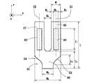
図3は本発明の第1実施例の水晶発振器に用いられる屈曲モードで振動する音叉形状の水晶振動子45の上面図である。音叉形状の屈曲水晶振動子45は、音叉腕46,47と音叉基部48とを具えて構成されている。即ち、音叉腕46,47の一端部が音叉基部48に接続されている。本実施例では、音叉基部48にはその幅が曲線的に徐々に狭くなる部分53、54が設けられている。この長さはl3で与えられ大略0.03mmから0.6mmを有する、好ましくは、0.1mmから0.6mmの範囲内にある。又、音叉基部の長さl2は0.3mmから0.85mmを有する。即ち、音叉基部の音叉部側の幅寸法W5と端部側の幅寸法W6はW5>W6を満たすように構成されている。本実施例では、徐々に狭くなる部分53、54は曲線的であるが、直線で徐々に狭くなるように形成しても良い。又、音叉腕46、47には中立線51、52を挟んで(含む)溝49、50が設けられている。本実施例では溝49、50は音叉腕46、47の一部に設けられている。図示されていないが、溝49、50に対抗して音叉腕の下面にも溝が設けられている。と共に溝の中と音叉腕の側面に電極が配置されている。そしてその対抗電極は極性が異なるように構成されている。又、振動子は音叉基部48の端部側で表面実装型のケースや円筒型のケースに半田や接着剤によって固定される。即ち、2電極端子を構成する。円筒型のケースの場合には2本のリード線に固定される。
【0015】
また、音叉形状の屈曲水晶振動子45は厚みtを有し、溝は厚みt1を有している。ここで言う厚みt1は溝の一番深いところの厚みを言う。その理由は水晶は異方性の材料のために、化学的エッチング法では各結晶軸の方向によりエッチングスピードが異なる。それ故、化学的エッチング法による溝の形成では溝の深さにバラツキが生じ、一様な形状に加工するのが極めて難しいためである。本実施例では、溝の厚みt1と音叉腕の厚みtとの比(t1/t)が0.79より小さくなるように溝が音叉腕に形成されている。このように形成することにより、音叉腕の溝側面電極とそれに対抗する側面の電極との間の電界Exが大きくなるので、電気機械変換効率の良い屈曲振動子が得られる。即ち、基本波モード振動の容量比r1が2次高調波モード振動の容量比r2より小さい音叉形状の屈曲水晶振動子が得られる。
【0016】
更に、部分幅W1、W3と溝幅W2とすると、音叉腕46,47の腕幅WはW=W1+W2+W3で与えられ、通常はW1とW3の一部又は全部がW1≧W3または、W1<W3となるように構成される。又、溝幅W2はW2≧W1,W3を満足する条件で構成される。更に具体的に述べると、本実施例では、溝幅W2と音叉腕幅Wとの比(W2/W)が0.35より大きく、1より小さくなるように、好ましくは、0.35〜0.95で、溝の厚みt1と音叉腕の厚みtとの比(t1/t)が0.79より小さくなるように、好ましくは、0.01〜0.79となるように溝が音叉腕に形成されている。このように形成することにより、音叉腕の中立線51、52を基点とする慣性モーメントが大きくなる。即ち、等価直列抵抗R1の小さい、Q値の高い音叉形状の屈曲水晶振動子を得る事ができる。
【0017】
更に、音叉形状の振動子45の全長lは要求される周波数や収納容器の大きさなどから決定されると共に、基本波モードで振動する良好な屈曲水晶振動子を得るためには、溝の長さl1と全長lとの間には密接な関係が存在する。
【0018】
すなわち、音叉腕46,47に設けられた溝の長さl1と音叉形状の屈曲水晶振動子の全長lとの比(l1/l)が0.2〜0.78となるように溝の長さは設けられる。このように形成する理由は、不要振動である2次高調波モード振動を抑える事ができると共に基本波モード振動の周波数安定性を高めることができる。それ故、基本波モードで容易に振動する良好な音叉形状の屈曲水晶振動子が実現できる。さらに詳述するならば、基本波モードで振動する音叉形状の屈曲水晶振動子の等価直列抵抗R1が2次高調波モード振動の等価直列抵抗R2より小さくなる。即ち、R1<R2となり、増幅器(CMOSインバータ)、コンデンサ、抵抗、本実施例の音叉形状の屈曲水晶振動子等から成る水晶発振器において、振動子が基本波モードで容易に振動する良好な水晶発振器が実現できる。また、溝の長さl1は音叉腕の長さ方向に分割されていても良く、その中の少なくとも1個が前記辺比(l1/l)を満足すれば良いか、又は、分割された溝の長さ方向の加えられた溝の長さが前記辺比(l1/l)を満足すれば良い。
【0019】
また、この実施例では、音叉基部48は図3中、振動子45の長さl2の下側部分全体とされ、又、音叉腕46及び音叉腕47は、図3中、振動子45の長さl2の部分から上側の部分全体とされている。
【0020】
換言するならば、音叉形状の音叉腕の中立線を挟んだ、即ち、中立線を含む音叉腕の上下面に各々少なくとも1個の溝が長さ方向に設けられ、前記溝の両側面に電極が配置され、前記溝側面の電極とその電極に対抗する音叉腕側面の電極とが互いに異極となるように構成されていて、音叉腕に生ずる慣性モーメントが大きくなるように前記各々少なくとも1個の溝の内少なくとも1個の溝幅W2と音叉腕幅Wとの比(W2/W)が0.35より大きく、1より小さく、且つ、前記溝の厚みt1と音叉腕の厚みtとの比(t1/t)が0.79より小さくなるように溝が形成されている。
【0021】
更に、本実施例の音叉腕の間隔はW4で与えられ、間隔W4と溝幅W2はW4≧W2を満足するように構成され、間隔W4は0.05mm〜0.35mmで、溝幅W2は0.03mm〜0.12mmの値を有する。このように構成する理由は超小型の屈曲水晶振動子で、かつ、音叉形状と音叉腕の溝をフオトリソグラフィ技術を用いて別々の工程で形成でき、更に、基本波モード振動の周波数安定性が高調波モード振動の周波数安定性より高くすることができる。この場合、本実施例では、厚みtは通常0.05mm〜0.12mmの水晶ウエハが用いられるが、0.12mmより厚い水晶ウエハを使用してもよい。
【0022】
更に詳述するならば、屈曲水晶振動子の誘導性と電気機械変換効率を表すフイガーオブメリットMiは品質係数Qi値と容量比riの比(Qi/ri)によって定義され(i=1のとき基本波モード振動、i=2のとき2次高調波モード振動)、屈曲水晶振動子の並列容量に依存しない機械的直列共振周波数fsと並列容量に依存する(直列)共振周波数frの周波数差ΔfはフイガーオブメリットMiに反比例し、その値Miが大きい程Δfは小さくなる。従って、Miが大きい程、屈曲水晶振動子の共振周波数は並列容量の影響を受けないので、屈曲水晶振動子の周波数安定性は良くなる。即ち、時間精度の高い音叉形状の屈曲水晶振動子が得られる。
【0023】
詳細には、前記音叉形状と溝と電極とその寸法の構成により、基本波モード振動のフイガーオブメリットM1が2次高調波モード振動のフイガーオブメリットM2より大きくなる。即ち、M1>M2となる。一例として、基本波モード振動の周波数が32.768kHzで、W2/W=0.5、t1/t=0.34、l1/l=0.48のとき、製造によるバラツキが生ずるが、音叉形状の屈曲水晶振動子のM1、M2はそれぞれM1>65、M2<30となる。即ち、高い誘導性と電気機械変換効率の良い(等価直列抵抗R1の小さい)、品質係数の大きい基本波モードで振動する屈曲水晶振動子を得ることができる。その結果、基本波モード振動の周波数安定性が2次高調波モード振動の周波数安定性より良くなると共に、2次高調波モード振動を抑圧することができる。また、本発明の基本波モード振動の基準周波数は10kHz〜200kHzが用いられる。特に、32.768kHzの振動子の製造方法については後述される。
【0024】
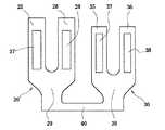
図4は本発明の第2実施例の水晶発振器に用いられる屈曲モードで振動する2個の音叉形状の水晶振動子20、30の上面図である。振動子20は音叉腕25,26と音叉基部29とを具えて構成されている。更に、音叉腕25,26には溝27,28が設けられている。同様に、振動子30は音叉腕35,36と音叉基部39とを具えて構成されている。更に、音叉腕35,36には溝37,38が設けられている。また、振動子20と振動子30は接続部40を介して音叉基部で接続され、一体に形成されている。本実施例では、電極は図示されていないが、振動子20と振動子30は周波数温度特性において頂点温度の異なる振動子で、かつ、それらは電気的に並列に接続されるように電極は構成されている。このように構成することにより、振動子の周波数温度特性を改善することができる。また、振動子20,30の形状は図3で述べた形状と同じであり、接続部40を介して両振動子は音叉基部で接続されている。振動子寸法又は溝の寸法又は両振動子間に角度を持たせることにより、頂点温度を変えることができる。また、両振動子間には振動干渉防止用の仕切り部を設けても良い。
【0025】
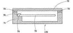
図5は本発明の第3実施例の水晶発振器に用いられる水晶ユニットの断面図である。水晶ユニット170は音叉形状の屈曲水晶振動子70、ケース71と蓋72を具えて構成されている。更に詳述するならば、振動子70はケース71に設けられた固定部74に導電性接着剤76や半田によって固定される。又、ケース71と蓋72は接合部材73を介して接合される。本実施例では、振動子70は図3で詳細に述べられた屈曲モードで振動する音叉形状の水晶振動子45と同じ振動子である。又、本実施例の水晶発振器では回路素子は水晶ユニットの外側に接続される。即ち、音叉形状の屈曲水晶振動子のみが真空中のユニット内に収納されている。本実施例では、水晶振動子は表面実装型の容器に収納されているが、円筒型の容器に収納しても良い。
【0026】
更に、ケースの部材はセラミックスかガラス、蓋の部材は金属かガラス、そして、接合部材は金属か低融点ガラスでできている。、本実施例で述べた振動子とケースと蓋との関係は以下に述べられる図6の水晶発振器にも適用される。
【0027】
図6は本発明の第4実施例の水晶発振器の断面図を示す。水晶発振器190は水晶発振回路とケース91と蓋92を具えて構成されている。本実施例では、水晶発振回路はケース91と蓋92から成る水晶ユニット内に収納されている。又、水晶発振回路は音叉形状の屈曲水晶振動子90と帰還抵抗を含む増幅器98とコンデンサー(図示されていない)とドレイン抵抗(図示されていない)を具えて構成されていて、増幅器98はCMOSインバータが用いられる。
【0028】
更に、本実施例では、振動子90はケース91に設けられた固定部94に接着剤96や半田によって固定される。これに対して、増幅器98はケース91に固定されている。また、ケース91と蓋92は接合部材93を介して接合されている。本実施例の振動子90は図3で詳細に述べられた音叉形状の屈曲水晶振動子45の振動子が用いられる。
【0029】
次に、本発明の水晶発振器の製造方法の実施例について、図面に記載の工程に従って述べる。図7は本発明の水晶発振器を構成する水晶ユニットを製造する工程である。即ち、本発明の水晶発振器の製造方法の一実施例の工程図である。記号S−1からS−12は工程の番号を示す。まず、S−1では水晶ウエハ140(断面図で示す)が準備される。次に、S−2ではその水晶ウエハ140の上面と下面に金属膜(例えば、クロムそしてその上に金、又は、金)141が蒸着法又はスパッタリング法により形成される。更に、S−3では前記金属膜141の上にレジスト142が塗布される。そして、フォトリソ工程により、それら金属膜141とレジスト142とが音叉形状を残して除去された後、エッチング加工(例えば、化学的エッチング法)により、S−4で示される音叉腕143,144と音叉基部145とを具えた音叉形状が形成される。この音叉形状を形成するときに、音叉基部に切り欠き部を形成しても良い。あるいは、音叉基部の叉付近の幅が音叉腕の自由端と反対側の方向に曲線的に徐々に狭くなる部分(図3参照)が存在するように音叉基部を形成しても良い。
【0030】
次に、S−2とS−3の工程で示したと同様に金属膜とレジストがS−4の音叉形状に塗布されて、フォトリソ工程とエッチング加工により、S−5で示される音叉腕143および音叉腕144に溝146,147,148,149が形成される。更に、S−5に金属膜とレジストが塗布されて、フォトリソ工程により極性が異なる電極がS−6で示されるように形成される。
【0031】
即ち、音叉腕143の側面に配置された電極150,153と音叉腕144の溝148,149に配置された電極155,156は同極となるように接続形成される。同様に、音叉腕143の溝146、147に配置された電極151,152と音叉腕144の側面に配置された電極154,157は同極となるように接続形成される。更に詳述するならば、溝の側面(段差部)と対抗する音叉腕の側面に互いに異なる極性を有する電極が配置されているので、音叉腕は基本波モード振動で、しかも逆相で屈曲振動をする。本実施例の工程では、水晶ウエハ内に1個の音叉形状の屈曲水晶振動子が示されているが、実際には、多数個の音叉形状の屈曲水晶振動子が水晶ウエハ内に形成され、それらの振動子の発振周波数は基本波モード振動で32.768kHzより高くなるように形成される。
【0032】
次の工程では、水晶ウエハ内に形成された多数個の音叉形状の屈曲水晶振動子の発振周波数が32.768kHzより低くなるように、スパッタリング法又は蒸着法又はメッキにて水晶ウエハ内の音叉腕に重り(金属膜)が付加、形成される。好ましくは、29.4kHzから32.75kHzの範囲内にある。重り(金属膜)の材料として、例えば、銀若しくは金が使用される。更に、次の工程では、音叉腕に形成された前記重り(金属膜)の一部又は全部をレーザ又はプラズマエッチング法によって除去し、発振周波数が32.2kHz〜33.08kHzの範囲内にあるように水晶ウエハ内で周波数調整がなされる。又、水晶ウエハ内に形成された音叉形状の屈曲水晶振動子は水晶ウエハ内で良振動子か不良振動子かの検査が行われる。そして、不良振動子が存在するときには、前記振動子は水晶ウエハから取り除かれるか、又はマーキングされるか又はコンピユタに記憶される。不良振動子には、例えば、発振不良(等価直列抵抗R1大)、欠け、周波数不良(周波数の変化大)、電極切れ、汚れ、外形形状不良等が含まれる。本実施例の工程では、音叉形状の加工後に重りを音叉腕に形成しているが、音叉形状の加工前に水晶ウエハに形成しても良い。
【0033】
本実施例では、S−3の工程から音叉形状を形成し、その後、音叉腕に溝を形成しているが、本発明は前記実施例に限定されるものではなくて、S−3の工程からまず溝を形成し、その後に音叉形状を形成しても良い。又は、音叉形状と溝を同時に形成しても良い。更に、音叉腕に設けられる溝は叉部より音叉腕の自由端方向の位置に形成しても良い。即ち、叉部より自由端側に設けられている。
【0034】
次の工程は矢印で示されるAとBの2つの方法がある。Aはケースに穴がない場合で、Bは穴がある場合である。まずAの工程では形成された音叉形状の屈曲水晶振動子160が水晶ウェハから切離され、その音叉基部145がS−7で示されるように、ケース158の固定部159に導電性接着剤161又は半田にて固定される。次に、S−8では水晶振動子160が真空中で封止されて水晶ユニットが形成され、その水晶ユニットを有する水晶発振回路が構成されたときに、バッフア回路を介して出力される発振周波数が32.764kHzから32.772kHzの範囲内にあるようにレーザ162又はプラズマエッチング法にて周波数が調整される。最後に、S−9で示すように、ケース158と蓋163とが低融点ガラス164又は半田などの金属を介して接合される。その結果、音叉形状の屈曲水晶振動子とケースと蓋とを具えて構成される水晶ユニットが得られる。この場合はケース158は真空封止用の穴を持たないので、接合は真空中で行われる。図示されていないが、更に周波数の偏差を小さくするために、蓋がガラスの場合には、S−9の後にレーザで周波数調整をしても良い。尚、レーザ又はプラズマエッチング法にて周波数調整するときには、音叉腕の重り(金属膜)の一部又は全部を除去して周波数調整される。Bの工程では穴がケースにあるが蓋でも良い。
【0035】
本実施例では、重り(金属膜)が水晶ウエハに形成された多数個の音叉形状の屈曲水晶振動子の音叉腕に形成され、その重り(金属膜)の一部又は全部をレーザ又はプラズマエッチング法にて除去して周波数調整しているが、本発明はこれに限定されるものではなく、即ち、これらの工程は省略しても良い。詳細には、水晶ウエハ内に形成された多数個の音叉形状の屈曲水晶振動子で、各々の振動子の基本波モード振動での発振周波数が32.768kHzより高い周波数を有する音叉形状の屈曲水晶振動子を各々のケースの固定部に固定し、その後に、水晶ユニットが形成され、その水晶ユニットを有する水晶発振回路が構成されたときに、バッフア回路を介して出力される発振周波数が32.764kHzから32.772kHzの範囲内にあるように蒸着法にて周波数調整される。蒸着法にて周波数調整されるときには、音叉腕に重り(金属)を付加して調整される。
【0036】
次にBの工程では、S−10で音叉形状の屈曲水晶振動子160が水晶ウェハから切離され、その音叉基部145がケース165の固定部159に導電性接着剤161又は半田にて固定される。次に、S−8と同じ様にして周波数調整が行われる。即ち、水晶振動子160が真空中で封止され、その水晶ユニットを有する水晶発振回路が構成されたときに、バッフア回路を介して出力される発振周波数が32.764kHzから32.772kHzの範囲内にあるようにレーザ又はプラズマエッチング法にて周波数調整される。更に、S−11では、ケース165と蓋163がS−9と同じ方法で接合される。その後に、真空中で周波数調整が行われる。好ましくは、水晶振動子160が真空中で封止されたときに、バッフア回路を介して出力される発振周波数が32.766kHzから32.77kHzになるようにレーザにて調整される。最後に、S−12では、ケース165に設けられた穴167が真空中で低融点ガラスや半田などの金属166を用いて封止される。
【0037】
このように、本実施例では、S−10の工程とS−11の工程の後とに周波数調整が行われるが、少なくともどちらか一方の工程の後に周波数調整をしても良い。更に詳述するならば、音叉形状の屈曲水晶振動子をケース又は蓋の固定部に固定し、その後に、水晶ユニットが形成され、その水晶ユニットを有する水晶発振回路が構成されたときに、バッフア回路を介して出力される発振周波数が32.764kHzから32.772kHzの範囲内にあるようにレーザ又はプラズマエッチング法によって周波数調整される。例えば、音叉形状の屈曲水晶振動子をケース又は蓋の固定部に固定し、ケースと蓋を接合した後に、レーザにて周波数調整される。この場合も水晶ユニットを形成し、バッフア回路を介して出力される発振周波数が32.764kHzから32.772kHzの範囲内にあるようにレーザによって周波数調整される。又、Aの工程と同じように、周波数の偏差を小さくするために、S−12の後にレーザで周波数調整をしても良い。この場合には、出力される発振周波数が32.766kHzから32.77kHzの範囲内にあるように周波数調整される。このように、本実施例では、周波数調整は複数回の別々の工程で行われるが、本発明では、少なくとも2回の別々の工程で周波数調整すれば良い。即ち、1回は水晶ウエハの状態で、更に、1回は振動子をケース、又は蓋に固定した後に周波数調整される。固定した後に、例えば、ケースと蓋を接合し、その後に周波数調整しても固定した後の周波数調整に含まれる。又、水晶振動子が真空中で封止された水晶ユニットを形成し、その後に、周波数調整をしても良い。この周波数調整の工程は別の1回の工程である。
【0038】
本実施例では、1個の音叉型屈曲水晶振動子を具える水晶ユニットの製造方法について説明したが、2個以上(複数個)の同一モードの振動子を具える水晶ユニットの場合も同じ工程で製造される。即ち、S−3の工程から2個以上の個々、又は、一体形成の音叉形状を形成し(S−4)、更に、S−5では少なくとも1個の音叉形状の音叉腕に溝、又は音叉腕と音叉基部とに溝、又は叉部付近で分割された、分割部を有する溝を形成し、S−6では各音叉型屈曲水晶振動子は逆相で振動するように電極が配置され、A工程(S−7〜S−9)又はB工程(S−10〜S−12)にて形成される。更に、周波数の偏差を小さくするために、S−9又はS−12の後にレーザで片方又は両振動子の周波数調整を行っても良い。この場合、両振動の周波数差は同じ負荷容量で30ppm以内にあるのが好ましい。
【0039】
尚、本実施例の製造工程で示された共振(発振)周波数の測定には、他励振法と自励振法の2つがある。本実施例の共振(発振)周波数の測定において、本発明はどちらの方法も含む。他励振法では、本実施例の共振(発振)周波数は、負荷容量CL値が18pF以下の容量を音叉形状の屈曲水晶振動子に直列に接続して位相が略零になるようにして測定したときの共振(発振)周波数である。例えば、CL値が6pF、又は9pF、又は12pF等である。即ち、18pF以下の任意の数値で測定したときの共振(発振)周波数である。測定にはインピーダンス アナライザー等の測定器が持ちいられる。これに対して、自励振法では、本実施例の発振(共振)周波数は水晶発振回路を構成し、負荷容量CL値が18pF以下の容量を有する回路構成にして測定したときの発振(共振)周波数である。好ましくは、1pFから18pFである。例えば、CL値が6pF、又は9pF、又は12pF等である。即ち、18pF以下の任意の数値で測定したときの発振(共振)周波数である。この場合、発振(共振)周波数はバッフア回路を介して出力信号として出力される。
【0040】
次に、上記実施例で示された水晶ユニットは水晶発振回路を具えて構成される本発明の水晶発振器を構成するのに用いられる。即ち、水晶発振回路は増幅回路と帰還回路とを具えて構成されていて、増幅回路は少なくとも増幅器から構成され、帰還回路は少なくとも音叉形状の屈曲水晶振動子を具えて構成される前記水晶ユニットとコンデンサーから構成されている。詳細には、増幅部はCMOSインバータと帰還抵抗とを具えて構成され、帰還部は前記水晶ユニットとドレイン抵抗とゲート側のコンデンサとドレイン側のコンデンサとを具えて構成されていて、これらの素子は電気的に接続されている。又、前記した発振周波数は水晶発振回路から出力される出力信号の周波数である。通常はバッフア回路を介して出力される。即ち、水晶発振回路の出力信号はバッフア回路を介して出力され、その出力信号の周波数は32.764kHzから32.772kHzの範囲内にある。
【0040】
上記方法で製造された本発明の水晶発振器は、超小型で、高い周波数安定性と高い時間精度を有する品質に優れた、安価な水晶発振器が実現できる。
【0041】
以上、図示例に基づき説明したが、この発明は上述の例に限定されるものではなく、上記実施例の水晶発振器に用いられる音叉形状の屈曲水晶振動子では、音叉腕又は音叉腕と音叉基部に溝を設けているが、例えば、音叉腕に貫通穴(t1=0)を設けてもよい。即ち、貫通穴は溝の特別の場合で、本発明の溝は前記貫通穴をも包含するものである。又、上記実施例では、音叉腕は2本で構成されているが、本発明は3本以上の音叉腕を包含するものである。この場合、少なくとも2本の音叉腕が逆相で振動するように電極が構成されていれば良い。
【0042】
更に、第1実施例〜第4実施例の水晶発振器とそれに用いられる音叉形状の屈曲水晶振動子について述べてきたが、これらの実施例の水晶発振器に用いられる水晶振動子はケースと蓋とから構成される、いわゆるユニット内に収納され、水晶ユニットを構成する。即ち、ケース又は蓋に設けられた固定部に導電性接着剤又は半田等によって固定部に本実施例の振動子は固定され、さらに、ケースと蓋とは接合部材を介して接合されていて、ケース内は真空になるように構成されている。このように構成することにより、等価直列抵抗R1の小さい、超小型の水晶ユニットを実現することができる。また、上記実施例では、音叉腕に溝が設けられているが、溝はなくても良い。即ち、音叉腕は上面と下面と側面とを有し、それらの面に音叉腕が逆相で振動するように電極が配置されている。
【0043】
また、音叉形状の屈曲水晶振動子の容量比r1、r2はそれぞれr1=C0/C1、r2=C0/C2で与えられる。但し、C0は電気的等価回路の並列容量で、C1とC2は電気的等価回路の基本波モード振動と2次高調波モード振動の等価容量である。更に、音叉形状の屈曲水晶振動子の基本波モード振動と2次高調波モード振動の品質係数はQ1値とQ2値で与えられる。そして、前記実施例の音叉形状の屈曲水晶振動子は、基本波モードで振動する共振周波数の並列容量による依存性が2次高調波モードで振動する共振周波数の並列容量による依存性より小さく成るように構成される。即ち、r1/2Q12<r2/2Q22を満たすように構成されている。このような構成により、基本波モードで振動する共振周波数の並列容量による影響が無視できるほど極めて小さくなるので、高い周波数安定性を有する基本波モードで振動する屈曲水晶振動が得られる。又、本発明では、r1/2Q12とr2/2Q22をそれぞれS1とS2と置き、S1とS2をそれぞれ基本波モード振動と2次高調波モード振動の周波数安定係数と呼ぶ。即ち、S1=r1/2Q12とS2=r2/2Q22で与えられる。
【0044】
更に、本実施例の屈曲水晶振動子の音叉形状と溝は化学的、物理的と機械的加工方法の内、少なくとも一つの方法を用いて加工される。物理的方法では、例えば、イオン化した原子、分子を飛散させて加工するものである。ここではこの方法をプラズマエッチング法と言う。又、機械的方法では、例えば、ブラスト加工用の粒子を飛散させて加工するものである。ここではこの方法を粒子法と言う。
【0045】
【発明の効果】
以上述べたように、本発明の水晶発振器とその製造方法を提供する事により多くの効果が得られることを既に述べたが、その中でも特に、次の如き著しい効果が得られる。
(1)音叉形状の屈曲水晶振動子を多数個ウエハ内に形成し、重りの形成および周波数調整をウエハ内で行うので、作業性に優れ、安価な振動子が得られ
ると同時に、安価な水晶発振器が実現できる。
(2)増幅回路の基本波モード振動の増幅率α1と2次高調波モード振動の増幅率α2との比が帰還回路の2次高調波モード振動の帰還率β2と基本波モード振動の帰還率β1との比より大きく、かつ、基本波モード振動の増幅率α1と基本波モード振動の帰還率β1の積が1より大きくなるように水晶発振器は構成されているので、負荷容量が小さくても、水晶発振器の出力信号は、基本波モード振動の周波数が出力として得られると共に、消費
電流の少ない水晶発振器が実現できる。
(3)基本波モード振動のフイガーオブメリットM1が2次高調波モード振動のフイガーオブメリットM2より大きい振動子を具えて水晶発振器は構成されるので、出力信号が基本波モード振動の周波数が得られると共に、高い周波数安定性を有する水晶発振器が実現できる。即ち、高い時間精度を有
する水晶発振器を得る事ができる。
【図面の簡単な説明】
【図1】 本発明の水晶発振器を構成する水晶発振回路図の一実施例である。
【図2】 図1の帰還回路図を示す。
【図3】 本発明の第1実施例の水晶発振器に用いられる屈曲モードで振動する音叉形状の水晶振動子の平面図である。
【図4】 本発明の第2実施例の水晶発振器に用いられる屈曲モードで振動する2個の音叉形状の水晶振動子の上面図で、一体に形成されている。
【図5】 本発明の第3実施例の水晶発振器に用いられる水晶ユニットの断面図である。
【図6】 本発明の第4実施例の水晶発振器の断面図を示す。
【図7】 本発明の水晶発振器を製造する方法の一実施例の工程図である。
【符号の説明】
1、9 増幅回路、帰還回路
V1、V2 入力電圧、出力電圧
W2、W、W4 溝幅、音叉腕の腕幅、音叉腕の間隔
W1、W3 音叉腕の部分幅
l1、l2、l 溝の長さ、音叉基部の長さ、音叉形状の屈曲水晶振動子の全長t、t1 音叉腕の厚み、溝の厚み[0001]
BACKGROUND OF THE INVENTION
The present invention provides a method for manufacturing a crystal oscillator including a crystal oscillation circuit including a tuning fork-shaped crystal resonator including a tuning fork arm and a tuning fork base that vibrate in a bending mode, an amplifier, a capacitor, and a resistance element. It relates to a crystal oscillator.
[0002]
[Prior art]
As a conventional crystal oscillator, a crystal oscillator composed of an amplifier, a capacitor, a resistance element, and a tuning fork-type bending crystal resonator in which electrodes are arranged on the upper, lower, and side surfaces of a tuning fork arm is well known. The tuning-fork-shaped bent quartz crystal used in this conventional crystal oscillator has two tuning-fork arms and a tuning-fork base, and excitation electrodes are arranged on the upper and lower surfaces and side surfaces of the tuning-fork arm. Yes. For example, electrodes having the same polarity are disposed on the upper and lower surfaces of one tuning fork arm, and electrodes having the same polarity are disposed on both side surfaces. That is, the electrodes on the upper and lower surfaces and the electrodes on both sides are configured to have different polarities. Similarly, electrodes having the same polarity are disposed on the upper and lower surfaces of the other tuning fork arm, and electrodes having the same polarity are disposed on both side surfaces. That is, the electrodes on the upper and lower surfaces and the electrodes on both sides are configured to have different polarities. Specifically, the electrodes on the upper and lower surfaces of one tuning fork arm and the electrodes on the upper and lower surfaces of the other tuning fork arm are configured to have different polarities. Therefore, when a voltage is applied between the electrodes, the electric field acts in a curve in the tuning fork arm. As a result, the electric field component Ex in the x-axis direction vibrates in the bending mode because the direction is reversed inside each tuning fork arm. Vibration can be sustained by applying an alternating voltage.
[0003]
[Problems to be solved by the invention]
The tuning-fork type flexural quartz crystal resonator, the more the electric field component Ex is greater losses equivalent series resistance R1 becomes smaller, the quality factor Q value increases. However, in the tuning fork-type bent quartz crystal resonator that has been conventionally used, electrodes are arranged on the upper and lower surfaces and side surfaces of each tuning fork arm. Therefore, the electric field does not work linearly, and if the tuning fork type bent quartz resonator is reduced in size, the electric field component Ex becomes smaller, the loss equivalent series resistance R1 becomes larger, the quality factor Q value becomes smaller, etc. The problem was left. At the same time, there remains a problem of obtaining a bent crystal resonator that is highly accurate as a time reference, that is, has high frequency stability and suppresses second harmonic mode vibration. As a method for solving the above-mentioned problem, for example, Japanese Patent Laid-Open No. 56-65517 discloses a groove on a tuning fork arm, and discloses a groove structure and an electrode structure. However, the configuration of the groove, Figa of merit M relating to relationships and the frequency stability of the equivalent series resistance R2 of the equivalent series resistance R1 of the second harmonic mode vibration in the vibration mode and fundamental mode vibration and dimension Is not disclosed at all. In addition, when a crystal oscillator is configured by connecting a conventional crystal resonator or a resonator having the groove to a conventional circuit, the output signal of the fundamental vibration mode is affected by impact, vibration, etc. There has been a problem that the frequency of the harmonic mode vibration is changed or detected. Therefore, a crystal oscillator comprising a tuning-fork-shaped bent quartz crystal that vibrates in a fundamental wave mode that suppresses second harmonic mode vibration that is not affected by shock or vibration. And a method for producing the same has been desired. Furthermore, to reduce the current consumption of the crystal oscillator, reducing the load capacitance CL liable to vibration second harmonic mode, problems such as not to obtain an output oscillation frequency of the fundamental mode oscillation is left It was. Therefore, a tuning fork shape that has an ultra-small size that vibrates in the fundamental mode, a small equivalent series resistance R1, a high quality factor Q value, a groove configuration and an electrode configuration with good electromechanical conversion efficiency. Therefore, there has been a demand for a crystal oscillator and a method of manufacturing the same which have a bent crystal resonator, an output signal having an oscillation frequency of fundamental mode vibration, high frequency stability (high time accuracy), and low current consumption.
[0004]
[Means for Solving the Problems]
An object of the present invention is to provide a crystal oscillator including a tuning fork-shaped crystal resonator that vibrates in a bending mode, which advantageously solves the conventional problems by the following method, and a method for manufacturing the crystal oscillator. .
[0005]
That is, the first aspect of the method for manufacturing a crystal resonator according to the present invention is a method for manufacturing a tuning-fork-type bending crystal resonator that vibrates in a fundamental wave mode and in an anti-phase bending mode and has two electrode terminals. Thetuning fork-type bending crystal resonator has a fundamental mode vibration and a second harmonic mode vibration, and the fundamental wave mode vibration of the advantage M1is the second harmonic mode vibration of the second harmonic mode vibration.Atuning fork shape, groove and electrode dimensions to be greater than2,a step of preparing a quartz wafer, a step of forming a first metal film on each of the top and bottom surfaces of the quartz wafer, A step of applying a first resist on the first metal film;and forming a tuning fork-shaped pattern on the quartz wafer , leaving the first fork-shaped metal film and the first resist, Remove the first metal film A step of forming a tuning fork shape including a tuning fork base and a tuning fork arm connected to the tuning fork base by a first etching process, and a second etching process different from the first etching process, Forming a groove oneach of theupper and lower surfaces of the tuning fork arm, forming a second metal film on the tuning fork-shaped surface having the groove on the tuning fork arm, and the tuning fork having the groove on the tuning fork arm. A step of applying a second resist on the second metal film formed on the surface of the shape, and forming a first electrode terminal of the two electrode terminals of thetuning-fork-type bending crystal resonator the tuning forkof the first electrode is formed on oneupper and lower surfaces ofeach of the grooves in the fork arms of thearm, thesecond electrode is formedon the side surface of the other tuning fork arm of theprevious SL tuning fork arms, and a first electrode The two-electrode terminal of thetuning fork-type bent quartz crystal resonator connected to the second electrode To form the second electrode terminal of the,a third electrode formed on a side surface of the one of the tuning forkarms, thefourth electrode is formedineach of the grooves ofthe uppersurface and the lower surface of thefront SL other tuning fork arm and, together with the third electrode and the fourth electrode is connected, the oscillation frequency of the fundamental mode vibration ofthe tuning fork type flexural quartz crystal resonator from the first electrode having a fourth electrode, formed higher than 32.768kHz Forming the fourth electrode from the first electrode in which the electrical polarity of the first electrode and the second electrode and the electrical polarity of the third electrode and the fourth electrode are different from each other; and the tuning fork type bent quartz crystal resonatorthe fundamental mode oscillation frequency of the oscillation of, so lower than 32.768kHz, forming a weight on the fork arms, is to have the method for manufacturing a quartz oscillator comprising a.
According to a second aspect of the method for manufacturing a crystal resonator of the present invention,after the step of forming the fourth electrode from the first electrode, a step of forming a weight on the tuning fork arm is performed, and the frequency stabilization of the fundamental mode vibration is performed. The coefficient S1and the frequency stability coefficient S2of thesecondharmonic mode vibration aredefined byS1= r1/ 2Q12and S2= r2/ 2Q22, and S1issmaller thanS2As described above, the method of manufacturing a crystal resonator according to the first aspectincludes a step of determining a tuning fork shape, a groove, and an electrode size .
According to a third aspect of the method for manufacturing a crystal resonator of the present invention, before the step of forming a weight on the tuning fork arm, the coating is performed on the second metal film to be a first electrode to a fourth electrode. The second resist is removed, and after the step of forming a weight on the tuning fork arm so that the oscillation frequency of the tuning fork type quartz crystal is lower than 32.768 kHz, the weight of the weight formed on the tuning fork arm is reduced. A part is removed by a laser or plasma etching method, and the oscillation frequency of thetuning-fork type bent quartz crystal resonator is adjusted in the quartz wafer so that it is in the range of 32.2 kHz to 33.08 kHz. It is a manufacturing method of a crystal oscillator given in amode or a 2nd mode.
[0006]
A first aspect of a method for manufacturing a crystal unit according to the present invention is a method for manufacturing a crystal unit comprising a crystal resonator, a case for storing the crystal resonator, and a lid connected to the case. the crystal oscillator in the fundamental mode, and vibrates in bending mode of reverse phase, with the tuning fork type flexural quartz crystal resonator having a second electrode terminal,the tuning-fork flexural crystal oscillators and
According to a second aspect of the method for producing a crystal unit of the present invention, thecase is provided with a through hole, the lid is a glass lid, and the glass lid is connected to the case via low-melting glass. A step of sealing a through-hole provided in the case in a vacuum using a metal after the step of connecting, and a step of sealing, and the oscillation frequency of the tuning-fork type quartz crystal resonator after the sealing step is 32 And a step of adjusting the oscillation frequency so as to be within a range of .764 kHz to 32.772 kHz .
A third aspect of the method for manufacturing a quartz unit of the present invention, a through hole provided in said casing, said lid is glass cap,connectingthe glass lid to the case through the low-melting glassAnd a step of sealing a through hole provided in the case with a metal in a vacuum, afterthe step of connectingthe glass lid to the case via a low melting point glass,and before the step of sealing in a vacuum with a metal through holes provided in the casing, a first aspectwhich includes the step of adjustingthe oscillation frequency of the tuning-fork flexural crystal oscillatortrue air a method for manufacturing a quartz unit accordingto.
A fourth aspect of the method for manufacturing a quartz unit of the present invention,the oscillation frequencybefore the SL tuning fork type flexural quartz crystal oscillator, so that less than 32.768kHz, after the step of forming a weight on the tuning fork arms, and, before the step of fixing thefront Symbol tuning-fork flexural crystal oscillatorto the fixing portion of the case, by removing a portion of the weight formed on the tuning fork arms, thesaid tuning-fork flexural crystal oscillator The method accordingto any one of the first to third aspects ,comprisinga step of adjustingtheoscillation frequency in the quartz wafer so that the oscillation frequency is in a range of 32.2 kHz to 33.08 kHz. This is a method for manufacturing a quartz unit.
A fifth aspect of the method for manufacturing a quartz unit of the present invention, after the step of fixing thefront Symbol tuning-fork flexural crystal oscillatorto a fixed portion of the casing, and, before the step of connectingthe cover tothe casethe oscillation frequencyof the tuning fork type flexural quartz crystal resonator is,the first to fourth embodiments are provided with a step of adjustingthe oscillation frequency to be within the scope of 32.764kHz~32.772kHz It is a manufacturing method of the crystal unit given inany 1 mode .
The first embodiment of the production method of the crystal oscillator of the present invention, amethod for manufacturing a quartz unitaccording to any one of the first aspect to fifth aspect, an amplifier, a capacitor, aresistor, a a quartz oscillator method of manufacturing with,said first electrode terminal of the fixed the tuning-fork type flexural quartz crystal resonator to the fixed part of the case andthe second electrode terminal and the amplifier, and the condenser, and the resistor It is a manufacturing method of the crystal oscillatorprovided with the process of electrically connecting.
[0007]
[Action]
Thus, the present invention is a method for manufacturing a crystal oscillator comprising a tuning-fork-shaped quartz crystal vibrator that vibrates in a bending mode, and further improves the tuning-fork-shaped groove or through-hole and electrode configuration and frequency adjustment method. By showing the relationship between the amplifier circuit and the feedback circuit, it is possible to obtain a crystal oscillator that suppresses harmonic vibration and outputs an oscillation frequency that vibrates in the fundamental vibration mode.
[0008]
[Embodiments of the Invention]
Embodiments of the present invention will be specifically described below with reference to the drawings.
FIG. 1 is an example of a crystal oscillation circuit diagram constituting a crystal oscillator of the present invention. In this embodiment, the
[0009]
FIG. 2 shows the feedback circuit diagram of FIG. Now, the angular frequency of the tuning-fork-shaped quartz crystal vibrating in the bending mode is ωi , the resistance of the
[0010]
Thus, from the relationship between the feedback rate βi and the load capacitance CL , when the load capacitance CL is reduced, the feedback rates of the oscillation frequencies of the fundamental mode vibration and the second harmonic mode oscillation are increased. Therefore, when the load capacitanceCL is reduced, the second harmonic mode vibration is more likely to oscillate than the fundamental mode vibration. The reason is that since the maximum vibration amplitude of the second harmonic mode vibration is smaller than the maximum vibration amplitude of the fundamental mode vibration, the amplitude condition and the phase condition, which are oscillation continuation conditions, are satisfied simultaneously.
[0011]
An object of the crystal oscillator of the present invention is to provide a crystal oscillator that has an oscillation frequency of fundamental mode vibration that has low current consumption and high frequency stability (high time accuracy). Therefore, in order to reduce current consumption, in the present embodiment, the load capacitance CL is used below 18 pF. In order to further reduce the current consumption, since the current consumption is proportional to the load capacity, CL = 15 pF or less is preferable. Further, in order to suppress the second harmonic mode vibration, the load capacitance CL value is preferably 1pF greater than. Furthermore, α1 / α2 > β2 / β1 and α1 β1 > 1 are satisfied in order to suppress the vibration of the second harmonic mode and to obtain the oscillation frequency of the fundamental mode vibration of the output signal of the oscillator. Thus, the crystal oscillation circuit of the present embodiment is configured. Where α1 and α2 are the amplification factors of the fundamental wave mode vibration and the second harmonic mode vibration amplification circuit, and β1 and β2 are the feedback factors of the feedback circuit of the fundamental wave mode vibration and the second harmonic mode vibration. It is.
[0012]
In other words, the ratio between the amplification factor α1 of the fundamental mode vibration of the amplifier circuit and the amplification factor α2 of the second harmonic mode vibration is equal to the feedback factor β2 of the second harmonic mode oscillation of the feedback circuit and the fundamental wave. greater than the ratio of the feedback factor beta1 mode vibration, and the product of the feedback factor beta1 amplification factor alpha1 and the fundamental mode vibration of the fundamental wave mode vibration is configured to be greater than 1. With such a configuration, it is possible to realize a crystal oscillator that consumes less current and whose output signal is the oscillation frequency of the fundamental mode vibration of a bent crystal resonator having a tuning fork shape. Further, high frequency stability will be described later.
[0013]
Further, the amplifying part of the amplifying circuit constituting the crystal oscillation circuit of the present embodiment can exhibit the characteristic by a negative resistance -RLi . When i = 1, it is a negative resistance of fundamental mode vibration, and when i = 2, it is a negative resistance of second harmonic mode vibration. In the crystal oscillation circuit of this embodiment, the ratio of the absolute value | −RL1 | of the negative resistance of the fundamental mode vibration of the amplifier circuit to the equivalent series resistance R1 of the fundamental mode vibration is the second harmonic of the amplifier circuit. The oscillation circuit is configured to be larger than the ratio of the absolute value | −RL2 | of the negative resistance of mode vibration to the equivalent series resistance R2 of second harmonic mode vibration. That is, it is configured to satisfy | −RL1 | / R1 > | −RL2 | / R2 . By configuring the crystal oscillation circuit in this manner, the oscillation activation of the second harmonic mode vibration can be suppressed, and as a result, the oscillation activation of the fundamental wave mode vibration can be obtained. can get.
[0014]
FIG. 3 is a top view of a tuning-fork-shaped
[0015]
Further, the
[0016]
Further, assuming that the partial widths W1 and W3 and the groove width W2 , the arm width W of the
[0017]
Further, the overall length l of the tuning-fork-shaped
[0018]
That is, the groove is formed such that the ratio (l1 / l) between the length l1 of the groove provided in the
[0019]
Further, in this embodiment, the
[0020]
In other words, at least one groove is provided in the length direction on the upper and lower surfaces of the tuning fork arm that includes the neutral line, ie, the tuning fork arm including the neutral line, and electrodes are formed on both sides of the groove. Are arranged such that the electrode on the side surface of the groove and the electrode on the side surface of the tuning fork arm that opposes the electrode are different from each other, and at least one of each of the electrodes is provided so that the moment of inertia generated in the tuning fork arm increases. The ratio (W2 / W) of the groove width W2 of at least one of the grooves to the tuning fork arm width W is larger than 0.35 and smaller than 1, and the thickness t1 of the groove and the thickness of the tuning fork arm The groove is formed so that the ratio (t1 / t) to t is smaller than 0.79.
[0021]
Further, the interval between the tuning fork arms of the present embodiment is given by W4 , and the interval W4 and the groove width W2 are configured to satisfy W4 ≧ W2 , and the interval W4 is 0.05 mm to 0.35 mm. in, the groove widthW 2 has a value of 0.03Mm~0.12Mm. The reason for this configuration is an ultra-compact bent quartz crystal resonator, and the tuning fork shape and tuning fork arm groove can be formed in separate steps using photolithography technology. Furthermore, the frequency stability of fundamental mode vibration is improved. It can be higher than the frequency stability of the harmonic mode vibration. In this case, in this embodiment, a quartz wafer having a thickness t of generally 0.05 mm to 0.12 mm is used, but a quartz wafer thicker than 0.12 mm may be used.
[0022]
More specifically, the Figer of Merit Mi representing the inductivity and electromechanical conversion efficiency of the bent crystal resonator is defined by the ratio of the quality factor Qi value and the capacity ratio ri (Qi / ri ). (Basic wave mode vibration when i = 1, second harmonic mode vibration when i = 2), mechanical series resonance frequency fs independent of parallel capacitance of the bent quartz crystal and parallel capacitance (series) the frequency difference Δf of the resonance frequency fr is inversely proportional to the full Iga of merit Mi, Δf becomes smaller as the value Mi is large. Therefore, as Mi is large, the resonance frequency of the bending crystal oscillator does not influenced by the parallel capacitance, the frequency stability of a flexural quartz crystal resonator is improved. That is, a tuning fork-shaped bent quartz crystal with high time accuracy can be obtained.
[0023]
Specifically, due to the configuration of the tuning fork shape, groove, electrode, and dimensions thereof, the fibre-of-merit M1 of the fundamental mode vibration becomes larger than the fibre-of-merit M2 of the second harmonic mode vibration. That is, M1 > M2 is satisfied. As an example, at the frequency of the fundamental mode oscillation32.768kHz, when W2 /W=0.5,t1 /t=0.34,l1 /l=0.48, although variations due to manufacturing may occur M1 and M2 of the tuning-fork-shaped bent quartz crystal resonator satisfy M1 > 65 and M2 <30, respectively. That is, (a small equivalent series resistance R1) Good high inductive electromechanical conversion efficiency, can be obtained flexural quartz oscillator that vibrates at a large fundamental mode of the quality factor. As a result, the frequency stability of the fundamental wave mode vibration becomes better than the frequency stability of the second harmonic mode vibration, and the second harmonic mode vibration can be suppressed. Further, the reference frequency of the fundamental wave mode vibration of the present invention is 10 kHz to 200 kHz. In particular, a method for manufacturing a 32.768 kHz vibrator will be described later.
[0024]
FIG. 4 is a top view of two tuning-fork-shaped
[0025]
FIG. 5 is a cross-sectional view of a crystal unit used in the crystal oscillator of the third embodiment of the present invention. The
[0026]
Further, the case member is made of ceramic or glass, the lid member is made of metal or glass, and the joining member is made of metal or low-melting glass. The relationship between the vibrator, the case, and the lid described in this embodiment is also applied to the crystal oscillator of FIG. 6 described below.
[0027]
FIG. 6 is a sectional view of a crystal oscillator according to a fourth embodiment of the present invention. The
[0028]
Further, in this embodiment, the
[0029]
Next, an embodiment of a method for manufacturing a crystal oscillator according to the present invention will be described in accordance with the steps shown in the drawings. FIG. 7 shows a process for manufacturing a crystal unit constituting the crystal oscillator of the present invention. That is, it is a process diagram of an embodiment of a method for manufacturing a crystal oscillator of the present invention. Symbols S-1 to S-12 indicate process numbers. First, in S-1, a quartz wafer 140 (shown in a sectional view) is prepared. Next, in S-2, a metal film (for example, chromium and gold or gold thereon) 141 is formed on the upper and lower surfaces of the
[0030]
Next, in the same manner as shown in the steps S-2 and S-3, a metal film and a resist are applied to the tuning fork shape of S-4, and the
[0031]
That is, the
[0032]
In the next step, the tuning fork arms in the quartz wafer are formed by sputtering, vapor deposition, or plating so that the oscillation frequency of a large number of tuning fork-shaped bent quartz resonators formed in the quartz wafer is lower than 32.768 kHz. A weight (metal film) is added and formed. Preferably, it is in the range of 29.4 kHz to 32.75 kHz. For example, silver or gold is used as the material of the weight (metal film). Further, in the next step, part or all of the weight (metal film) formed on the tuning fork arm is removed by laser or plasma etching so that the oscillation frequency is in the range of 32.2 kHz to 33.08 kHz. The frequency is adjusted in the quartz wafer. Further, the tuning fork-shaped bent quartz crystal formed in the quartz wafer is inspected as a good or defective vibrator within the quartz wafer. When a defective vibrator is present, the vibrator is removed from the quartz wafer, marked, or stored in a computer. Defective transducer, for example, the oscillation defect (equivalent series resistance R1 is large), chipping, frequency defect (the frequency of change is large), the electrode breakage, dirt, include outer shape defects like. In the process of this embodiment, the weight is formed on the tuning fork arm after the tuning fork shape is processed, but it may be formed on the quartz wafer before the tuning fork shape is processed.
[0033]
In the present embodiment, the tuning fork shape is formed from the step S-3, and then the groove is formed in the tuning fork arm. However, the present invention is not limited to the above embodiment, and the step S-3 is performed. First, a groove may be formed, and then a tuning fork shape may be formed. Or you may form a tuning fork shape and a groove | channel simultaneously. Furthermore, the groove provided in the tuning fork arm may be formed at a position in the free end direction of the tuning fork arm from the fork. That is, it is provided on the free end side from the fork.
[0034]
There are two methods for the next step, A and B indicated by arrows. A is the case where there is no hole in the case, and B is the case where there is a hole. First, in step A, the formed tuning fork-shaped bent
[0035]
In this embodiment, a weight (metal film) is formed on the tuning fork arms of a large number of tuning fork-shaped bent quartz resonators formed on a quartz wafer, and a part or all of the weight (metal film) is laser or plasma etched. However, the present invention is not limited to this, that is, these steps may be omitted. More specifically, a tuning-fork-shaped bent quartz crystal having a number of tuning-fork-shaped bent quartz resonators formed in a quartz wafer, each of which has an oscillation frequency higher than 32.768 kHz in the fundamental mode vibration. When the vibrator is fixed to the fixing portion of each case, and then a crystal unit is formed and a crystal oscillation circuit having the crystal unit is configured, the oscillation frequency output through the buffer circuit is 32. The frequency is adjusted by vapor deposition so that it is within the range of 764 kHz to 32.772 kHz. When the frequency is adjusted by vapor deposition, the tuning fork arm is adjusted by adding a weight (metal).
[0036]
Next, in step B, the tuning fork-shaped bent
[0037]
As described above, in this embodiment, the frequency adjustment is performed after the step S-10 and after the step S-11. However, the frequency adjustment may be performed after at least one of the steps. More specifically, when a tuning fork-shaped bent quartz crystal unit is fixed to a fixing part of a case or a lid, and then a crystal unit is formed and a crystal oscillation circuit including the crystal unit is configured, a buffer is formed. The frequency is adjusted by laser or plasma etching so that the oscillation frequency output through the circuit is in the range of 32.764 kHz to 32.772 kHz. For example, a tuning fork-shaped bent quartz crystal unit is fixed to a fixing part of a case or a lid, and after the case and the lid are joined, the frequency is adjusted by a laser. Also in this case, a crystal unit is formed, and the frequency is adjusted by the laser so that the oscillation frequency output through the buffer circuit is in the range of 32.764 kHz to 32.772 kHz. Similarly to the step A, the frequency may be adjusted with a laser after S-12 in order to reduce the frequency deviation. In this case, the frequency is adjusted so that the output oscillation frequency is in the range of 32.766 kHz to 32.77 kHz. Thus, in this embodiment, the frequency adjustment is performed in a plurality of separate steps, but in the present invention, the frequency adjustment may be performed in at least two separate steps. That is, the frequency adjustment is performed once in the state of the crystal wafer, and further once after the vibrator is fixed to the case or the lid. After fixing, for example, the case and the lid are joined, and the frequency adjustment after that is included in the frequency adjustment after fixing. Alternatively, the crystal unit in which the crystal unit is sealed in a vacuum may be formed, and then the frequency may be adjusted. This frequency adjustment process is another one-time process.
[0038]
In the present embodiment, a method for manufacturing a crystal unit including one tuning-fork-type bending crystal resonator has been described. However, the same steps apply to a crystal unit including two or more (plural) resonators of the same mode. Manufactured by. That is, two or more individual or integrally formed tuning fork shapes are formed from the step S-3 (S-4), and further, at S-5, at least one tuning fork shaped tuning fork arm has a groove or tuning fork. A groove having a divided portion, which is divided at or near the fork portion, is formed in the arm and the tuning fork base portion, and in S-6, electrodes are arranged so that each tuning fork type quartz crystal vibrator vibrates in reverse phase, It is formed in step A (S-7 to S-9) or step B (S-10 to S-12). Furthermore, in order to reduce the frequency deviation, the frequency of one or both vibrators may be adjusted with a laser after S-9 or S-12. In this case, the frequency difference between both vibrations is preferably within 30 ppm with the same load capacity.
[0039]
Note that there are two methods of measuring the resonance (oscillation) frequency shown in the manufacturing process of this embodiment: a separate excitation method and a self-excitation method. In the measurement of the resonance (oscillation) frequency of this embodiment, the present invention includes both methods. In other excitation method, the resonance (oscillation) frequency of the present example, measured as the phase are connected in series becomes substantially zero in the load capacitor CL value flexural crystal oscillator of the tuning fork shape following capacity 18pF This is the resonance (oscillation) frequency. For example,C L value 6pF, or 9 pF, or 12pF like. That is, the resonance (oscillation) frequency when measured with an arbitrary numerical value of 18 pF or less. Measurement equipment such as an impedance analyzer can be used for measurement. In contrast, in the self-excited method, the oscillation (resonance) frequency of the present embodiment constitutes a crystal oscillation circuit, the oscillation (resonance when the load capacitance CL value is measured in the circuit arrangement having the following capacity 18pF ) Frequency. Preferably, it is 1 pF to 18 pF. For example,C L value 6pF, or 9 pF, or 12pF like. That is, the oscillation (resonance) frequency when measured with an arbitrary numerical value of 18 pF or less. In this case, the oscillation (resonance) frequency is output as an output signal via the buffer circuit.
[0040]
Next, the crystal unit shown in the above embodiment is used to configure the crystal oscillator of the present invention configured to include a crystal oscillation circuit. That is, the crystal oscillation circuit includes an amplification circuit and a feedback circuit, the amplification circuit includes at least an amplifier, and the feedback circuit includes at least a tuning fork-shaped bent crystal resonator. Consists of capacitors. Specifically, the amplification unit includes a CMOS inverter and a feedback resistor, and the feedback unit includes the crystal unit, a drain resistor, a gate-side capacitor, and a drain-side capacitor. Are electrically connected. The oscillation frequency is the frequency of the output signal output from the crystal oscillation circuit. Usually, it is output via a buffer circuit. That is, the output signal of the crystal oscillation circuit is output through the buffer circuit, and the frequency of the output signal is in the range of 32.764 kHz to 32.772 kHz.
[0040]
The crystal oscillator of the present invention manufactured by the above method can realize an inexpensive crystal oscillator which is ultra-compact, excellent in quality having high frequency stability and high time accuracy.
[0041]
Although the present invention has been described based on the illustrated examples, the present invention is not limited to the above-described example, and the tuning fork arm or the tuning fork arm and the tuning fork base are used in the tuning fork-shaped bent crystal resonator used in the crystal oscillator of the above-described embodiment. For example, a through hole (t1 = 0) may be provided in the tuning fork arm. That is, the through hole is a special case of a groove, and the groove of the present invention includes the through hole. In the above embodiment, the tuning fork arm is composed of two, but the present invention includes three or more tuning fork arms. In this case, the electrodes may be configured so that at least two tuning fork arms vibrate in opposite phases.
[0042]
Furthermore, the crystal oscillators of the first to fourth embodiments and the tuning-fork-shaped bent crystal resonators used in the crystal oscillators have been described. The crystal resonators used in the crystal oscillators of these embodiments include a case and a lid. The crystal unit is configured by being housed in a so-called unit. That is, the vibrator of the present embodiment is fixed to the fixing portion by a conductive adhesive or solder or the like on the fixing portion provided on the case or the lid, and the case and the lid are bonded via the bonding member, The case is configured to be a vacuum. With this configuration, a small equivalent series resistance R1, it is possible to realize a subminiature quartz crystal unit. In the above embodiment, the tuning fork arm is provided with a groove, but the groove may not be provided. That is, the tuning fork arm has an upper surface, a lower surface, and a side surface, and electrodes are arranged on these surfaces so that the tuning fork arm vibrates in reverse phase.
[0043]
The capacitance ratios r1 and r2 of the tuning fork-shaped bent quartz crystal resonator are given by r1 = C0 / C1 and r2 = C0 / C2 , respectively. However, C0 is a parallel capacitance of the electrical equivalent circuit, and C1 and C2 are equivalent capacitances of the fundamental mode vibration and the second harmonic mode vibration of the electrical equivalent circuit. Further, the quality factor of the fundamental mode vibration and the second harmonic mode vibration of the tuning fork-shaped bent quartz crystal resonator is given by Q1 value and Q2 value. In the tuning fork-shaped bent quartz resonator of the above embodiment, the dependency of the resonance frequency oscillating in the fundamental wave mode due to the parallel capacitance is smaller than the dependency of the resonance frequency oscillating in the second harmonic mode due to the parallel capacitance. Configured. That is, it is configured to satisfy r1 / 2Q12 <r2 / 2Q22 . With such a configuration, the influence of the parallel capacitance of the resonance frequency oscillating in the fundamental wave mode is so small that it can be ignored, so that a bent crystal oscillation oscillating in the fundamental wave mode having high frequency stability can be obtained. Further, in the present invention, r1 / 2Q12 and r2 / 2Q22 are respectively set as S1 and S2 , and S1 and S2 are respectively frequency-stable for fundamental mode vibration and second harmonic mode vibration. Called coefficient. That is, S1 = r1 / 2Q12 and S2 = r2 / 2Q22 are given.
[0044]
Further, the tuning fork shape and the groove of the bent quartz crystal resonator of this embodiment are processed by using at least one of chemical, physical and mechanical processing methods. In the physical method, for example, ionized atoms and molecules are scattered and processed. Here, this method is called a plasma etching method. In the mechanical method, for example, particles for blasting are scattered and processed. Here, this method is called a particle method.
[0045]
【The invention's effect】
As described above, it has already been described that many effects can be obtained by providing the crystal oscillator of the present invention and the manufacturing method thereof, and among them, the following remarkable effects can be obtained.
(1) Since a large number of tuning fork-shaped bent crystal resonators are formed in a wafer, weight formation and frequency adjustment are performed in the wafer, it is possible to obtain an inexpensive resonator with excellent workability and at the same time an inexpensive crystal An oscillator can be realized.
(2) The ratio of the amplification factor α1 of the fundamental wave mode vibration of the amplifier circuit and the amplification factor α2 of the second harmonic mode vibration is the feedback factor β2 of the second harmonic mode vibration of the feedback circuit and the fundamental mode vibration. greater than the ratio of the feedback factor beta1 in and since the crystal oscillator is constructed as the product of the feedback factor beta1 amplification factor alpha1 and the fundamental mode vibration of the fundamental wave mode vibration is greater than 1, Even if the load capacitance is small, the output signal of the crystal oscillator can obtain the fundamental mode vibration frequency as an output, and a crystal oscillator with low current consumption can be realized.
(3) Since the full Iga of merit M1 of the fundamental wave mode vibration is a crystal oscillator comprises a full Iga of merit M2 is larger than transducers of the second harmonic mode vibration is configured, the output signal is the fundamental mode vibration A crystal oscillator having high frequency stability can be realized. That is, a crystal oscillator having high time accuracy can be obtained.
[Brief description of the drawings]
FIG. 1 is an example of a crystal oscillation circuit diagram constituting a crystal oscillator of the present invention.
FIG. 2 shows a feedback circuit diagram of FIG.
FIG. 3 is a plan view of a tuning-fork-shaped crystal resonator that vibrates in a bending mode used in the crystal oscillator according to the first embodiment of the present invention.
FIG. 4 is a top view of two tuning-fork-shaped crystal resonators that vibrate in a bending mode used in the crystal oscillator according to the second embodiment of the present invention, and are integrally formed.
FIG. 5 is a cross-sectional view of a crystal unit used in a crystal oscillator according to a third embodiment of the present invention.
FIG. 6 is a sectional view of a crystal oscillator according to a fourth embodiment of the present invention.
FIG. 7 is a process diagram of an embodiment of a method for producing a crystal oscillator of the present invention.
[Explanation of symbols]
1, 9 Amplification circuit, feedback circuit V1 , V2 input voltage, output voltage W2 , W, W4 groove width, tuning fork arm width, tuning fork arm spacing W1 , W3 tuning fork arm partial width l1 , L2 , l groove length, tuning fork base length, total length t of tuning fork-shaped bent quartz crystal, t1 tuning fork arm thickness, groove thickness
Claims (9)
Translated fromJapanese前記音叉型屈曲水晶振動子は基本波モード振動と2次高調波モード振動を備え、
前記基本波モード振動のフイガーオブメリットM1が、前記2次高調波モード振動のフイガーオブメリットM2より大きくなるように、音叉形状と溝と電極の寸法を決定する工程と、
水晶ウエハを準備する工程と、
前記水晶ウエハの上面と下面の各々に第1金属膜を形成する工程と、
前記第1金属膜の上に第1レジストを塗布する工程と、
前記水晶ウエハ上に音叉形状のパターンを形成するために、音叉形状の第1金属膜と第1レジストを残して前記第1レジストと前記第1金属膜を除去する工程と、
第1のエッチング加工により、音叉基部と前記音叉基部に接続された音叉腕とを備えた音叉形状を形成する工程と、
第1のエッチング加工と異なる第2のエッチング加工により、前記音叉腕の対抗する上面と下面の各々に溝を形成する工程と、
音叉腕に溝を有する前記音叉形状の面の上に第2金属膜を形成する工程と、
音叉腕に溝を有する前記音叉形状の面の上に形成された前記第2金属膜の上に第2レジストを塗布する工程と、
前記音叉型屈曲水晶振動子の前記2電極端子の内の第1電極端子を形成するために、前記音叉腕の一方の音叉腕の上面と下面の各々の溝に第1電極を形成し、前記音叉腕の他方の音叉腕の側面に第2電極を形成し、かつ、第1電極と第2電極とが接続され、前記音叉型屈曲水晶振動子の前記2電極端子の内の第2電極端子を形成するために、前記一方の音叉腕の側面に第3電極を形成し、前記他方の音叉腕の上面と下面の各々の溝に第4電極を形成し、かつ、第3電極と第4電極とが接続されると共に、第1電極から第4電極を有する前記音叉型屈曲水晶振動子の基本波モード振動の発振周波数が、32.768kHzより高く形成され、第1電極と第2電極の電気的極性と第3電極と第4電極の電気的極性とが異極性となる第1電極から第4電極を形成する工程と、
前記音叉型屈曲水晶振動子の前記基本波モード振動の発振周波数が、32.768kHzより低くなるように、前記音叉腕に重りを形成する工程と、を備えていることを特徴とする水晶振動子の製造方法。In a method for manufacturing a tuning fork-type bending quartz crystal resonator that vibrates in a fundamental wave mode and in a bending mode of opposite phase, and has two electrode terminals,
The tuning fork type quartz crystal resonator has a fundamental mode vibration and a second harmonic mode vibration.
Whereintheoff Iga of merit M1of the fundamental wave modevibration,the second harmonic modeto be larger than thefull Iga of merit M2of thevibration,and determining the size of the tuning fork and the groove and the electrode,
Preparing a crystal wafer;
Forming a first metal film on each of an upper surface and a lower surface of the quartz wafer;
Applying a first resist on the first metal film;
Removing the first resist and the first metal film while leavingthe tuning fork-shaped first metal film and the first resistto form a tuning fork-shaped pattern on the quartz wafer;
Forming a tuning fork shape comprising a tuning fork base and a tuning fork arm connected to the tuning fork base by a first etching process;
Forming a groove oneach of theupper and lowersurfaces facing the tuning fork arm by a second etching process different from the first etching process;
Forming a second metal film on the tuning-fork-shaped surface having a groove in the tuning-fork arm;
Applying a second resist on the second metal film formed on the tuning-fork-shaped surface having a groove in the tuning-fork arm;
In order to form the first electrode terminal of the two electrode terminals of thetuning fork type quartz crystal resonator , a first electrode is formed ineach grooveon theupper surface and the lowersurface of one tuning fork arm of the tuning fork arm. A second electrode is formed on the side surfaceof the other tuning fork arm of the tuning fork arm, the first electrode and the second electrode are connected, and the second electrode of the two electrode terminals of thetuning fork-type bending crystal resonator to form the terminal,a third electrode formed on a side surface of the one of the tuning forkarms, thefourth electrode is formedineach of the grooves ofthe uppersurface and the lower surface of thefront SL other tuning fork arm, and the third electrode If with the fourth electrode are connected,the tuning-fork flexural oscillation frequency of the fundamental mode oscillation of a quartz oscillator from the first electrode having a fourth electrode, formed higher than 32.768kHz, a first electrode first The first electrode from the first electrode in which the electrical polarity of the two electrodes and the electrical polarity of the third electrode and the fourth electrode are different from each other. Forming an electrode,
Crystal oscillatorthe oscillation frequency of the fundamental mode vibration of the tuning fork type flexural quartz crystal oscillator, so that less than 32.768kHz, characterized in that it comprises a step of forming a weight on the tuning fork arms Manufacturing method.
前記水晶振動子は基本波モードで、かつ、逆相の屈曲モードで振動し、2電極端子を備えた音叉型屈曲水晶振動子で、
前記音叉型屈曲水晶振動子は基本波モード振動と2次高調波モード振動を備え、
前記基本波モード振動のフイガーオブメリットM1が、前記2次高調波モード振動のフイガーオブメリットM2より大きくなるように、音叉形状と溝と電極の寸法を決定する工程と、
水晶ウエハを準備する工程と、
前記水晶ウエハの上面と下面の各々に第1金属膜を形成する工程と、
前記第1金属膜の上に第1レジストを塗布する工程と、
前記水晶ウエハ上に音叉形状のパターンを形成するために、音叉形状の第1金属膜と第1レジストを残して前記第1レジストと前記第1金属膜を除去する工程と、
第1のエッチング加工により、音叉基部と前記音叉基部に接続された音叉腕とを備えた音叉形状を形成する工程と、
第1のエッチング加工と異なる第2のエッチング加工により、前記音叉腕の対抗する上面と下面の各々に溝を形成する工程と、
音叉腕に溝を有する前記音叉形状の面の上に第2金属膜を形成する工程と、
音叉腕に溝を有する前記音叉形状の面の上に形成された前記第2金属膜の上に第2レジストを塗布する工程と、
前記音叉型屈曲水晶振動子の前記2電極端子の内の第1電極端子を形成するために、前記音叉腕の一方の音叉腕の上面と下面の各々の溝に第1電極を形成し、前記音叉腕の他方の音叉腕の側面に第2電極を形成し、かつ、第1電極と第2電極とが接続され、前記音叉型屈曲水晶振動子の前記2電極端子の内の第2電極端子を形成するために、前記一方の音叉腕の側面に第3電極を形成し、前記他方の音叉腕の上面と下面の各々の溝に第4電極を形成し、かつ、第3電極と第4電極とが接続されると共に、第1電極から第4電極を有する前記音叉型屈曲水晶振動子の基本波モード振動の発振周波数が、32.768kHzより高く形成され、第1電極と第2電極の電気的極性と第3電極と第4電極の電気的極性とが異極性となる第1電極から第4電極を形成する工程と、
前記音叉型屈曲水晶振動子の前記基本波モード振動の発振周波数が、32.768kHzより低くなるように、前記音叉腕に重りを形成する工程と、
前記ケースの固定部に前記音叉型屈曲水晶振動子を固定する工程と、
前記蓋を前記ケースに接続する工程と、を備えていることを特徴とする水晶ユニットの製造方法。In a method for manufacturing a crystal unit comprising a crystal resonator, a case for storing the crystal resonator, and a lid connected to the case,
The quartz crystal unit is a tuning fork type quartz crystal unit that vibrates in a fundamental wave mode and in an anti-phase bending mode, and has two electrode terminals.
The tuning fork type quartz crystal resonator has a fundamental mode vibration and a second harmonic mode vibration.
Whereintheoff Iga of merit M1of the fundamental wave modevibration,the second harmonic modeto be larger than thefull Iga of merit M2of thevibration,and determining the size of the tuning fork and the groove and the electrode,
Preparing a crystal wafer;
Forming a first metal film on each of an upper surface and a lower surface of the quartz wafer;
Applying a first resist on the first metal film;
Removing the first resist and the first metal film while leavingthe tuning fork-shaped first metal film and the first resistto form a tuning fork-shaped pattern on the quartz wafer;
Forming a tuning fork shape comprising a tuning fork base and a tuning fork arm connected to the tuning fork base by a first etching process;
By the second etching process different from the first etching process, a step of forming a groovein each of the uppersurface and the lower surface against the tuning fork arms,
Forming a second metal film on the tuning-fork-shaped surface having a groove in the tuning-fork arm;
Applying a second resist on the second metal film formed on the tuning-fork-shaped surface having a groove in the tuning-fork arm;
In order to form the first electrode terminal of the two electrode terminals of thetuning fork type quartz crystal resonator , a first electrode is formed ineach grooveon theupper surface and the lowersurface of one tuning fork arm of the tuning fork arm. A second electrode is formed on the side surfaceof the other tuning fork arm of the tuning fork arm, the first electrode and the second electrode are connected, and the second electrode of the two electrode terminals of thetuning fork-type bending crystal resonator to form the terminal,a third electrode formed on a side surface of the one of the tuning forkarms, thefourth electrode is formedineach of the grooves oftheupper and lower surfaces of thefront SL other tuning fork arm, and a third electrode with the fourth electrode is connected, the oscillation frequency of the fundamental mode vibration ofthe tuning fork type flexural quartz crystal resonator from the first electrode having a fourth electrode, formed higher than 32.768kHz, first electrode and the second The first electrode from which the electrical polarity of the electrode is different from the electrical polarity of the third electrode and the fourth electrode Forming an electrode,
The oscillation frequency of the fundamental mode vibration of the tuning fork type flexural quartz crystal oscillator, so that less than 32.768kHz, forming a weight on the tuning fork arms,
And fixing thepre-Symbol tuning-fork flexural crystal oscillatorto a fixed portion of the casing,
Method for manufacturing a quartz unit, characterized in that it comprises a, a step of connectingthe lidbefore SL case.
Priority Applications (1)
| Application Number | Priority Date | Filing Date | Title |
|---|---|---|---|
| JP2003158697AJP4517332B2 (en) | 2003-04-28 | 2003-04-28 | Quartz crystal unit, crystal unit and crystal oscillator manufacturing method |
Applications Claiming Priority (1)
| Application Number | Priority Date | Filing Date | Title |
|---|---|---|---|
| JP2003158697AJP4517332B2 (en) | 2003-04-28 | 2003-04-28 | Quartz crystal unit, crystal unit and crystal oscillator manufacturing method |
Related Child Applications (3)
| Application Number | Title | Priority Date | Filing Date |
|---|---|---|---|
| JP2008288223ADivisionJP5135566B2 (en) | 2008-10-14 | 2008-10-14 | Quartz crystal unit, crystal unit, crystal oscillator, and method of manufacturing the same |
| JP2010087308ADivisionJP4556201B2 (en) | 2010-03-17 | 2010-03-17 | Crystal resonator, crystal unit, and crystal oscillator manufacturing method |
| JP2010094456ADivisionJP4836016B2 (en) | 2010-03-30 | 2010-03-30 | Quartz crystal unit, crystal unit and crystal oscillator manufacturing method, crystal unit, crystal unit and crystal oscillator |
Publications (3)
| Publication Number | Publication Date |
|---|---|
| JP2004328701A JP2004328701A (en) | 2004-11-18 |
| JP2004328701A5 JP2004328701A5 (en) | 2008-05-29 |
| JP4517332B2true JP4517332B2 (en) | 2010-08-04 |
Family
ID=33508470
Family Applications (1)
| Application Number | Title | Priority Date | Filing Date |
|---|---|---|---|
| JP2003158697AExpired - Fee RelatedJP4517332B2 (en) | 2003-04-28 | 2003-04-28 | Quartz crystal unit, crystal unit and crystal oscillator manufacturing method |
Country Status (1)
| Country | Link |
|---|---|
| JP (1) | JP4517332B2 (en) |
Families Citing this family (7)
| Publication number | Priority date | Publication date | Assignee | Title |
|---|---|---|---|---|
| JP5184142B2 (en)* | 2008-02-26 | 2013-04-17 | セイコーインスツル株式会社 | Piezoelectric vibrating piece, piezoelectric vibrator, oscillator, electronic device, radio timepiece, and method of manufacturing piezoelectric vibrating piece |
| JP5782707B2 (en)* | 2010-12-01 | 2015-09-24 | セイコーエプソン株式会社 | Electronics |
| JP4556201B2 (en)* | 2010-03-17 | 2010-10-06 | 有限会社ピエデック技術研究所 | Crystal resonator, crystal unit, and crystal oscillator manufacturing method |
| JP5872314B2 (en)* | 2012-02-13 | 2016-03-01 | エスアイアイ・クリスタルテクノロジー株式会社 | Piezoelectric vibrating piece, piezoelectric vibrator, oscillator, electronic device, and radio timepiece |
| JP6115205B2 (en)* | 2013-03-13 | 2017-04-19 | セイコーエプソン株式会社 | Bending vibration piece, method for manufacturing bending vibration piece, vibration device, electronic apparatus, and moving body |
| JP6111754B2 (en)* | 2013-03-13 | 2017-04-12 | セイコーエプソン株式会社 | Bending vibration piece, method for manufacturing bending vibration piece, vibration device, electronic apparatus, and moving body |
| JP2014179802A (en)* | 2013-03-14 | 2014-09-25 | Seiko Epson Corp | Vibrator, oscillator, electronic apparatus and mobile |
Family Cites Families (9)
| Publication number | Priority date | Publication date | Assignee | Title |
|---|---|---|---|---|
| FR2467487A1 (en)* | 1979-10-15 | 1981-04-17 | Ebauches Sa | PIEZOELECTRIC RESONATOR |
| JPS5824884A (en)* | 1982-07-28 | 1983-02-14 | Seiko Instr & Electronics Ltd | Quartz time piece |
| JP2756559B2 (en)* | 1987-11-11 | 1998-05-25 | セイコーインスツルメンツ株式会社 | Manufacturing method of piezoelectric vibrator |
| JPH07212161A (en)* | 1994-01-18 | 1995-08-11 | Citizen Watch Co Ltd | Manufacture of crystal oscillator |
| JP4852195B2 (en)* | 1999-01-20 | 2012-01-11 | セイコーエプソン株式会社 | Tuning fork crystal unit |
| JP3729249B2 (en)* | 2000-09-01 | 2005-12-21 | セイコーエプソン株式会社 | Vibrating piece manufacturing method, vibrating piece, vibrator having vibrating piece, oscillator, and mobile phone device |
| JP2002118423A (en)* | 2000-10-06 | 2002-04-19 | Seiko Epson Corp | Piezoelectric device and its manufacturing method |
| JP2002261575A (en)* | 2000-12-25 | 2002-09-13 | Seiko Epson Corp | Vibrating reed, vibrator, oscillator and electronic equipment |
| JP2003008381A (en)* | 2001-06-25 | 2003-01-10 | Seiko Epson Corp | Method for mounting piezoelectric vibrating reed, mounting jig for piezoelectric vibrating reed, and piezoelectric vibrator |
- 2003
- 2003-04-28JPJP2003158697Apatent/JP4517332B2/ennot_activeExpired - Fee Related
Also Published As
| Publication number | Publication date |
|---|---|
| JP2004328701A (en) | 2004-11-18 |
Similar Documents
| Publication | Publication Date | Title |
|---|---|---|
| JP2005039767A (en) | Crystal unit, crystal unit and crystal oscillator | |
| JP5135566B2 (en) | Quartz crystal unit, crystal unit, crystal oscillator, and method of manufacturing the same | |
| JP5531319B2 (en) | Crystal resonator, crystal unit, and crystal oscillator manufacturing method | |
| JP4517332B2 (en) | Quartz crystal unit, crystal unit and crystal oscillator manufacturing method | |
| JP4836016B2 (en) | Quartz crystal unit, crystal unit and crystal oscillator manufacturing method, crystal unit, crystal unit and crystal oscillator | |
| JP4556201B2 (en) | Crystal resonator, crystal unit, and crystal oscillator manufacturing method | |
| JP2003273703A (en) | Quartz vibrator and its manufacturing method | |
| JP4411494B2 (en) | Crystal oscillator | |
| JP3749917B2 (en) | Manufacturing method of crystal oscillator | |
| JP4074934B2 (en) | Crystal oscillator and manufacturing method thereof | |
| JP4074935B2 (en) | Quartz crystal oscillator and crystal oscillator manufacturing method | |
| JP4697196B2 (en) | Crystal unit and crystal oscillator manufacturing method | |
| JP4697196B6 (en) | Crystal unit and crystal oscillator manufacturing method | |
| JP2007202210A (en) | Crystal unit having flexural mode quartz crystal resonator | |
| JP4697190B2 (en) | Manufacturing methods for crystal units and crystal units | |
| JP4697190B6 (en) | Manufacturing methods for crystal units and crystal units | |
| JP2003273696A (en) | Method for manufacturing crystal unit and method of manufacturing crystal oscillator | |
| JP4411496B2 (en) | Portable device equipped with crystal oscillator and manufacturing method thereof | |
| JP2003273647A (en) | Crystal oscillator and method of manufacturing the same | |
| JP2003273695A (en) | Crystal unit and crystal oscillator | |
| JP2003273702A (en) | Quartz unit, its manufacturing method, and quartz oscillator | |
| JP2003273701A (en) | Quartz oscillator | |
| JP2003273697A (en) | Crystal oscillator, and method of manufacturing crystal oscillator | |
| JP2003229721A (en) | Crystal oscillator |
Legal Events
| Date | Code | Title | Description |
|---|---|---|---|
| A621 | Written request for application examination | Free format text:JAPANESE INTERMEDIATE CODE: A621 Effective date:20060426 | |
| A521 | Request for written amendment filed | Free format text:JAPANESE INTERMEDIATE CODE: A523 Effective date:20061106 | |
| A521 | Request for written amendment filed | Free format text:JAPANESE INTERMEDIATE CODE: A523 Effective date:20080222 | |
| A977 | Report on retrieval | Free format text:JAPANESE INTERMEDIATE CODE: A971007 Effective date:20080604 | |
| A131 | Notification of reasons for refusal | Free format text:JAPANESE INTERMEDIATE CODE: A131 Effective date:20080812 | |
| A521 | Request for written amendment filed | Free format text:JAPANESE INTERMEDIATE CODE: A523 Effective date:20081014 | |
| A131 | Notification of reasons for refusal | Free format text:JAPANESE INTERMEDIATE CODE: A131 Effective date:20090303 | |
| A521 | Request for written amendment filed | Free format text:JAPANESE INTERMEDIATE CODE: A523 Effective date:20090430 | |
| A131 | Notification of reasons for refusal | Free format text:JAPANESE INTERMEDIATE CODE: A131 Effective date:20100302 | |
| A521 | Request for written amendment filed | Free format text:JAPANESE INTERMEDIATE CODE: A523 Effective date:20100304 | |
| TRDD | Decision of grant or rejection written | ||
| A01 | Written decision to grant a patent or to grant a registration (utility model) | Free format text:JAPANESE INTERMEDIATE CODE: A01 Effective date:20100427 | |
| A01 | Written decision to grant a patent or to grant a registration (utility model) | Free format text:JAPANESE INTERMEDIATE CODE: A01 | |
| A61 | First payment of annual fees (during grant procedure) | Free format text:JAPANESE INTERMEDIATE CODE: A61 Effective date:20100506 | |
| FPAY | Renewal fee payment (event date is renewal date of database) | Free format text:PAYMENT UNTIL: 20160528 Year of fee payment:6 | |
| R150 | Certificate of patent or registration of utility model | Ref document number:4517332 Country of ref document:JP Free format text:JAPANESE INTERMEDIATE CODE: R150 Free format text:JAPANESE INTERMEDIATE CODE: R150 | |
| R250 | Receipt of annual fees | Free format text:JAPANESE INTERMEDIATE CODE: R250 | |
| R250 | Receipt of annual fees | Free format text:JAPANESE INTERMEDIATE CODE: R250 | |
| LAPS | Cancellation because of no payment of annual fees |