JP4514800B2 - Wiper blade device for automobile - Google Patents
Wiper blade device for automobileDownload PDFInfo
- Publication number
- JP4514800B2 JP4514800B2JP2007551182AJP2007551182AJP4514800B2JP 4514800 B2JP4514800 B2JP 4514800B2JP 2007551182 AJP2007551182 AJP 2007551182AJP 2007551182 AJP2007551182 AJP 2007551182AJP 4514800 B2JP4514800 B2JP 4514800B2
- Authority
- JP
- Japan
- Prior art keywords
- rail spring
- spoiler
- blade
- wiper blade
- rail
- Prior art date
- Legal status (The legal status is an assumption and is not a legal conclusion. Google has not performed a legal analysis and makes no representation as to the accuracy of the status listed.)
- Expired - Fee Related
Links
- 238000010168coupling processMethods0.000claimsabstractdescription21
- 238000005859coupling reactionMethods0.000claimsabstractdescription21
- 230000008878couplingEffects0.000claimsabstractdescription20
- 238000009434installationMethods0.000claimsabstractdescription9
- 230000002265preventionEffects0.000claimsabstractdescription8
- 230000007246mechanismEffects0.000claimsdescription13
- 230000037431insertionEffects0.000claimsdescription5
- 238000003780insertionMethods0.000claimsdescription5
- 239000000463materialSubstances0.000claimsdescription5
- 230000003014reinforcing effectEffects0.000claimsdescription4
- 238000005452bendingMethods0.000claimsdescription3
- 230000008275binding mechanismEffects0.000claimsdescription3
- 150000002500ionsChemical class0.000abstract2
- 239000000306componentSubstances0.000description5
- 238000000926separation methodMethods0.000description3
- 239000008358core componentSubstances0.000description2
- 239000011521glassSubstances0.000description2
- 230000002787reinforcementEffects0.000description2
- XLYOFNOQVPJJNP-UHFFFAOYSA-NwaterSubstancesOXLYOFNOQVPJJNP-UHFFFAOYSA-N0.000description2
- 239000000470constituentSubstances0.000description1
- 230000000694effectsEffects0.000description1
- 239000005357flat glassSubstances0.000description1
- 230000007774longtermEffects0.000description1
- 230000003252repetitive effectEffects0.000description1
Images


Classifications
- B—PERFORMING OPERATIONS; TRANSPORTING
- B60—VEHICLES IN GENERAL
- B60S—SERVICING, CLEANING, REPAIRING, SUPPORTING, LIFTING, OR MANOEUVRING OF VEHICLES, NOT OTHERWISE PROVIDED FOR
- B60S1/00—Cleaning of vehicles
- B60S1/02—Cleaning windscreens, windows or optical devices
- B60S1/04—Wipers or the like, e.g. scrapers
- B60S1/32—Wipers or the like, e.g. scrapers characterised by constructional features of wiper blade arms or blades
- B60S1/38—Wiper blades
- B60S1/3848—Flat-type wiper blade, i.e. without harness
- B60S1/3849—Connectors therefor; Connection to wiper arm; Attached to blade
- B60S1/3851—Mounting of connector to blade assembly
- B60S1/3858—Mounting of connector to blade assembly with protrusions cooperating with holes
- B—PERFORMING OPERATIONS; TRANSPORTING
- B60—VEHICLES IN GENERAL
- B60S—SERVICING, CLEANING, REPAIRING, SUPPORTING, LIFTING, OR MANOEUVRING OF VEHICLES, NOT OTHERWISE PROVIDED FOR
- B60S1/00—Cleaning of vehicles
- B60S1/02—Cleaning windscreens, windows or optical devices
- B60S1/04—Wipers or the like, e.g. scrapers
- B60S1/32—Wipers or the like, e.g. scrapers characterised by constructional features of wiper blade arms or blades
- B60S1/38—Wiper blades
- B60S1/3848—Flat-type wiper blade, i.e. without harness
- B60S1/3874—Flat-type wiper blade, i.e. without harness with a reinforcing vertebra
- B60S1/3882—C-shape section
- B—PERFORMING OPERATIONS; TRANSPORTING
- B60—VEHICLES IN GENERAL
- B60S—SERVICING, CLEANING, REPAIRING, SUPPORTING, LIFTING, OR MANOEUVRING OF VEHICLES, NOT OTHERWISE PROVIDED FOR
- B60S1/00—Cleaning of vehicles
- B60S1/02—Cleaning windscreens, windows or optical devices
- B60S1/04—Wipers or the like, e.g. scrapers
- B60S1/32—Wipers or the like, e.g. scrapers characterised by constructional features of wiper blade arms or blades
- B60S1/40—Connections between blades and arms
- B—PERFORMING OPERATIONS; TRANSPORTING
- B60—VEHICLES IN GENERAL
- B60S—SERVICING, CLEANING, REPAIRING, SUPPORTING, LIFTING, OR MANOEUVRING OF VEHICLES, NOT OTHERWISE PROVIDED FOR
- B60S1/00—Cleaning of vehicles
- B60S1/02—Cleaning windscreens, windows or optical devices
- B60S1/04—Wipers or the like, e.g. scrapers
- B60S1/32—Wipers or the like, e.g. scrapers characterised by constructional features of wiper blade arms or blades
- B60S1/38—Wiper blades
- B60S1/3806—Means, or measures taken, for influencing the aerodynamic quality of the wiper blades
- B60S1/381—Spoilers mounted on the squeegee or on the vertebra
- B—PERFORMING OPERATIONS; TRANSPORTING
- B60—VEHICLES IN GENERAL
- B60S—SERVICING, CLEANING, REPAIRING, SUPPORTING, LIFTING, OR MANOEUVRING OF VEHICLES, NOT OTHERWISE PROVIDED FOR
- B60S1/00—Cleaning of vehicles
- B60S1/02—Cleaning windscreens, windows or optical devices
- B60S1/04—Wipers or the like, e.g. scrapers
- B60S1/32—Wipers or the like, e.g. scrapers characterised by constructional features of wiper blade arms or blades
- B60S1/38—Wiper blades
- B60S1/3848—Flat-type wiper blade, i.e. without harness
- B60S1/3874—Flat-type wiper blade, i.e. without harness with a reinforcing vertebra
- B60S1/3875—Flat-type wiper blade, i.e. without harness with a reinforcing vertebra rectangular section
- B60S1/3881—Flat-type wiper blade, i.e. without harness with a reinforcing vertebra rectangular section in additional element, e.g. spoiler
- B—PERFORMING OPERATIONS; TRANSPORTING
- B60—VEHICLES IN GENERAL
- B60S—SERVICING, CLEANING, REPAIRING, SUPPORTING, LIFTING, OR MANOEUVRING OF VEHICLES, NOT OTHERWISE PROVIDED FOR
- B60S1/00—Cleaning of vehicles
- B60S1/02—Cleaning windscreens, windows or optical devices
- B60S1/04—Wipers or the like, e.g. scrapers
- B60S1/32—Wipers or the like, e.g. scrapers characterised by constructional features of wiper blade arms or blades
- B60S1/38—Wiper blades
- B60S2001/3812—Means of supporting or holding the squeegee or blade rubber
Landscapes
- Engineering & Computer Science (AREA)
- Mechanical Engineering (AREA)
- Clamps And Clips (AREA)
- Insertion Pins And Rivets (AREA)
- Pivots And Pivotal Connections (AREA)
- Cleaning Implements For Floors, Carpets, Furniture, Walls, And The Like (AREA)
- Window Of Vehicle (AREA)
- Structures Of Non-Positive Displacement Pumps (AREA)
Abstract
Description
Translated fromJapanese本発明は、自動車用ワイパーブレードの作動時、揺れがなく、より確実な密着力を持つことで、車両のフロントガラス面に付着された雨水や異物等をより効率よく且つ完壁に払拭できるようにすると共に、ブレード装置をなす各構成要素間の有機的結合構造をより強固に向上できる、自動車用ワイパーブレード装置に関する。 The present invention is capable of wiping rain water and foreign matters attached to the windshield of the vehicle more efficiently and completely on the wall by having a more reliable adhesion without shaking when the wiper blade for an automobile is operated. In addition, the present invention relates to a wiper blade device for automobiles that can more firmly improve the organic coupling structure between the components constituting the blade device.
従来、ワイパーブレード装置は、一定の撓み性及び剛性を持つ狭幅の2つのレールスプリングをブレードの上部の両側面の嵌合溝に嵌合したり、広幅のレールスプリングに長い溝をパンチング形成し、そこにブレードの上部を嵌合して固定したりする構造であるため、堅固性が落ちるという問題点があった。つまり、上述したように、狭幅の2つに分離したものや、広幅の1つのレールスプリングに長い溝を形成し、そこにブレードを結合した場合、レールスプリング体は幅方向に広まったり、互いに密着されて狭くなる現象が発生する。よって、長時間ワイパーを作動する場合、レールスプリング間の結合関係が緩くなり、その間に嵌合されたブレード部品及びレールスプリングの上部外側に囲まれたスポイラー部品の離脱又は損傷が発生するという問題点があった。 Conventionally, a wiper blade device has two narrow rail springs with a certain degree of flexibility and rigidity fitted in the fitting grooves on both sides of the upper part of the blade, or a long groove is punched in a wide rail spring. Since the upper part of the blade is fitted and fixed there, there is a problem that the rigidity is lowered. In other words, as described above, when a long groove is formed in one narrow spring or a wide rail spring, and a blade is coupled thereto, the rail spring bodies spread in the width direction, The phenomenon of being narrowed by close contact occurs. Therefore, when the wiper is operated for a long time, the connection relationship between the rail springs becomes loose, and the blade part fitted between them and the spoiler part surrounded by the upper outer side of the rail spring may be detached or damaged. was there.
また、軟質ゴム材からなり、ワイパーブレード装置の核心構成要素であるブレード部品は、レールスプリングに直接嵌合された状態で車両のガラス面と摩擦作動するように設けられているため、ブレード及びガラス面間のクリアランスにより、ワイパー作動の際、揺れが生じ、ウィンドウガラスとの間に優れた密着関係を維持できないという問題点があるだけでなく、その嵌合部が剛性を持つレールスプリング材質と繰返し接触により破れる等、円滑且つ完壁なワイパー作動に大きい支障を招いた。 In addition, the blade component, which is made of a soft rubber material and is the core component of the wiper blade device, is provided so as to frictionally act on the glass surface of the vehicle while being directly fitted to the rail spring. Due to the clearance between the surfaces, there is a problem that the wiper is shaken when the wiper is operated, and it is not possible to maintain an excellent close relationship with the window glass. This caused a great hindrance to smooth and complete wiper operation, such as breaking by contact.
さらに、作動アームに連結したクランプ及びレールスプリング間の連結結合時、単純にそのレールスプリング部分を加圧し曲げることにより結合された弱い構造であるため、使用中クリアランスが生じてしまい左右に揺れたり、さらに激しい場合はゆるみが一層増して分離されるという問題点もある。 Furthermore, when connecting between the clamp and rail spring connected to the operating arm, it is a weak structure that is connected by simply pressurizing and bending the rail spring part, so a clearance occurs during use and it swings left and right, In the case of more severe cases, there is also a problem that loosening is further separated.
本発明は上記の諸点を解決すべく講じられたものであり、その目的は、ワイパー構成要素の核心構成要素であるブレード部品がレールスプリングと嵌合するとき、クリアランスを最小化し、安全且つ堅固な結合構造を持つブレード結合構造と、レールスプリングに形成された長い溝の脆弱性を補完できる強度補強手段と、レールスプリングの上部の中間地点に装着されるクランプ及びレールスプリング間の、効率よく且つ堅固な連結手段とを提供することにある。 The present invention has been devised to solve the above-mentioned problems, and its purpose is to minimize the clearance when the blade component, which is the core component of the wiper component, is fitted with the rail spring, so that it is safe and robust. A blade coupling structure with a coupling structure, a strength reinforcing means that can compensate for the weakness of the long groove formed in the rail spring, and the clamp and rail spring mounted at the midpoint of the upper part of the rail spring are efficient and robust. Providing a connecting means.
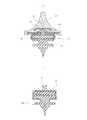
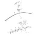
前記目的を達成するために、本発明は、ワイパーブレード装置の骨格であるレールスプリング(100)の上段に空気の抵抗を最小化するスポイラー(200)を備え、底面部には軟質ゴム材からなるブレード(300)が嵌合され、長手方向の上段の中間地点にクランプ(400)が装着されるワイパーブレード装置において、前記ブレード(300)がレールスプリング(100)に直接嵌合されるものでなく、別途の固定結束機構(10)を前記レールスプリング(100)に固定した後、前記固定結束機構(10)に前記ブレード(300)を結合できるようにし、前記ブレード(300)を結束するために、前記レールスプリング(100)にパンチング形成されたブレード嵌合溝(110)に一つ以上の強度補強部(120)を備え、前記レールスプリング(100)の長手方向の上段の中間地点に結束/装着されるクランプ(400)が、前記レールスプリング(100)間により確実に結束かつ保持できるよう、前記レールスプリング(100)の幅方向の両端に係合凹部(131)を形成し、一つ以上の係合凸部(132)が形成されているクランプ結合部(130)を備える一方、これと対応するクランプ(400)側の底面両端には、前記レールスプリング(100)側の係合凹部(131)及び係合凸部(132)に強固に挿入係合する係合孔(411)を有する結合曲げ部(410)を一つ以上下方に突設して互いに係合するようにし、及び前記レールスプリング(100)の幅方向の両端部に挟持されるスポイラー(200)の“コ”字状のウィング部の外側面に離脱防止溝(211)が内設している複数のクリップ設置部(210)を備え、該クリップ設置部(210)には、スポイラーと共に、前記レールスプリング(100)の一部分を上下把持してスポイラーの離脱を防止する離脱防止用クリップ(220)を締結して構成することを含むワイパーブレード装置を提供する。 In order to achieve the above object, the present invention comprises a spoiler (200) for minimizing air resistance at the upper stage of a rail spring (100) which is a skeleton of a wiper blade device, and a bottom portion is made of a soft rubber material. In the wiper blade device in which the blade (300) is fitted and the clamp (400) is mounted at the upper middle point in the longitudinal direction, the blade (300) is not directly fitted to the rail spring (100). In order to bind the blade (300) so that the blade (300) can be coupled to the fixed bundling mechanism (10) after fixing the separate bundling mechanism (10) to the rail spring (100). The blade fitting groove (110) punched in the rail spring (100) is provided with one or more strength reinforcing portions (120), and is bound / interposed at an intermediate point in the upper longitudinal direction of the rail spring (100). The clamp (400) to be installed is Engagement recesses (131) are formed at both ends of the rail spring (100) in the width direction so that the rail springs (100) can be bound and held more securely, and one or more engagement projections (132) are formed. On the other hand, there are engaging recesses (131) and engaging protrusions (132) on the rail spring (100) side at both ends of the bottom surface on the clamp (400) side corresponding thereto. One or more coupling bent portions (410) having engaging holes (411) that are firmly inserted and engaged with each other so as to protrude downward and engage with each other, and both ends of the rail spring (100) in the width direction A plurality of clip installation portions (210) having a separation preventing groove (211) provided on the outer surface of the "U" -shaped wing portion of the spoiler (200) sandwiched between the portions, the clip installation portion ( 210) includes a spoiler and a part of the rail spring (100) that holds the top and bottom to prevent the spoiler from being detached. It has entered into use clip (220) to provide a wiper blade apparatus comprising configuring.
本発明のワイパーブレード装置は、ブレード部材がより確実な密着力で円滑に旋回作動することによって、車両のフロントガラス面に付着された雪や雨水等の異物をより清潔且つ完壁に除去でき、さらには与えられる構造的堅固性による振動防止、故障率低下、寿命延長、機能向上などの効果を提供することができる。 The wiper blade device of the present invention can remove foreign matters such as snow and rain water adhered to the windshield surface of the vehicle more cleanly and completely, by smoothly turning the blade member with a more reliable adhesion force, Furthermore, it is possible to provide effects such as vibration prevention, failure rate reduction, life extension, and function improvement due to the provided structural rigidity.
以下、添付図面に基づき、本発明の好適な実施形態を詳細に説明する。 Hereinafter, preferred embodiments of the present invention will be described in detail with reference to the accompanying drawings.
本発明の構成要素のうち、ブレード固定結束機構10は、図に示すように、上側に、レールスプリング100の嵌合溝110に挿入され、固定溝21が形成された突出部20を備え、下側では、レールスプリング面に密着している上、ブレードを安全且つ堅固にクランプ結合できるようにする“コ”字状のループ30が左右対称的に形成される。 Of the constituent elements of the present invention, as shown in the figure, the blade fixing and
前記固定溝21には、レールスプリング100に強固に結合できるようにするウェッジフット41を有するウェッジ40を設入して構成される。 The fixed
また、“コ”字状のループ30は、実施形態に示すように、上、下段に追加的に構成する場合、より堅固な結合力が得られるので、適宜に選択して構成できることは言うまでもない。 Further, as shown in the embodiment, when the “U” -
また、ウェッジ40は、レールスプリング100の上部に組み立てて設けられるスポイラー200の底面にループ挿入溝230を形成する一方、ウェッジ40の上部両端にそのループ挿入溝230に係止できるループ42をさらに形成した後、互いに組立てると、下側の固定結束機構10の結合堅固性がより向上できると共に、スポイラー200の結合性までも合わせて向上できるというダブルメリットが得られる。 In addition, the
また、固定結束機構10は、図に示すように、レールスプリング100が車両のフロントガラスの曲率による撓みの発生のため、自由な撓み性が要求されるので、前述した固定結束機構10を所定の短い長さで各々等分配列して構成し、レールスプリング100の撓み性に直ぐ適応できるように構成することもできると共に、固定結束機構10の構成のうち、上部に突出している突出部20とその下側の“コ”字状のループ30の上段下方の一定深さまで隙間31を形成すれば、これもまた必要な所定の撓み性を十分に付与できる。 Further, as shown in the figure, the fixed
このように構成できる本発明は、前述と同様、ブレードがレールスプリングに直接嵌合するものではなく、種々の材質で成形できると共に、様々な形状や形態に具現でき、ひいてはレールスプリングの底面にクリアランスを最小化した状態でほぼ完全に密着させた固定結束機構を介してブレードを結合できるようにすることで、ワイパー作動時、クリアランスや振動が全くなく、より円滑な作動及び確実なガラス面との間の密着性が得られる。これは、ワイパー性能向上に大きく寄与できる主要構成要素であると言える。 In the present invention that can be configured in this manner, the blade is not directly fitted to the rail spring, as described above, but can be formed of various materials and can be embodied in various shapes and forms. By allowing the blades to be connected via a fixed bundling mechanism that is almost completely in close contact with the wiper being minimized, there is no clearance or vibration at the time of wiper operation, smoother operation and a reliable glass surface. Adhesion between them is obtained. This can be said to be a main component that can greatly contribute to improving the wiper performance.
また、ブレードを結束させるために、レールスプリングにパンチング形成したブレード結合溝に一つ以上の硬度補強部を備えたことは、ワイパーブレード装置の骨格となるレールスプリングの構造上の脆弱性を補うのに大きく寄与できる。すなわち、結合溝が必要以上に長く形成されると、その分両側のレールスプリング間の結合力が弱くなりワイパー全体の構造的な脆弱性につながるため、品質向上のために必ず要求される部分である。しかしながら、これに対して従来は、両側レールスプリングの間を一定に広げてブレード上段部を嵌めなければならない構造的な理由により、補強手段そのものを考慮することができなった。 In addition, in order to bind the blades, one or more hardness reinforcements are provided in the blade coupling grooves punched in the rail springs to compensate for the structural weakness of the rail springs that form the skeleton of the wiper blade device. Can greatly contribute. In other words, if the coupling groove is formed longer than necessary, the coupling force between the rail springs on both sides will be weakened, leading to structural weakness of the entire wiper. is there. However, conventionally, the reinforcing means itself could not be taken into account for the structural reason that the upper stage portion of the blade must be fitted with a constant spread between the rail springs on both sides.
また、レールスプリングの長手方向の上部の中間地点にクランプを結合する時、レールスプリングの幅方向の両端に係合凹部をパンチング形成し、一つ以上の係合凸部を形成したクランプ結合部を備える一方、これに対応するクランプ側の底面両端には、スプリング側の係合凹部及び係合凸部に強固に係止する係合孔を有する結合曲げ部を、一つ以上下方に突設して互いに結合させることで、使用中にクランプ及びレールスプリング間の把持状態が多少緩くなっている場合であっても、係合孔を有する結合曲げ部がレールスプリング側の結合部の係合凸部及び係合凹部に揺動することなくほぼ完壁な結合状態が維持できるようになる。 In addition, when the clamp is coupled to the intermediate point at the upper part in the longitudinal direction of the rail spring, the engagement concave portion is punched at both ends in the width direction of the rail spring, and the clamp coupling portion having one or more engagement convex portions is formed. On the other hand, at one end of the bottom surface on the clamp side corresponding to this, one or more coupling bent portions having engaging holes that are firmly locked to the engaging concave portions and the engaging convex portions on the spring side protrude downward. Even if the grip between the clamp and the rail spring is somewhat loose during use, the coupling bent portion having the engagement hole is the engagement convex portion of the coupling portion on the rail spring side. In addition, it is possible to maintain a substantially complete coupled state without swinging into the engaging recess.
レールスプリングの幅方向の両側端部に挟持して設けられるスポイラーの“コ”字状のウィング部の外側面に離脱防止溝を内設している複数のクリップ設置部を備え、そのクリップ設置部には、スポイラーと共に、レールスプリングの一部分を上下把持してスポイラーの離脱を防止する離脱防止用クリップを締結して構成することは、レールスプリングに挟持されているスポイラーの基本結束力だけでは使用中に発生し得るその他の衝撃や長時間使用時に発生し得る反復振動、揺れ等によりスポイラーが離脱する恐れを完全に解消できない。そこで、基本的な把持力に加えてスポイラーの弱い材質とは関係なく多様な剛性、弾性、把持力等の特性を自由に与えられる別の把持手段、すなわち、離脱防止手段を追加したことにその目的がある。 Provided with a plurality of clip installation parts with release prevention grooves on the outer surface of the "U" -shaped wing part of the spoiler provided to be sandwiched between both ends in the width direction of the rail spring, and the clip installation parts In addition to the spoiler, it is used only by the basic binding force of the spoiler that is sandwiched between the rail springs, and is configured by fastening a clip for preventing removal of the spoiler by clamping a part of the rail spring up and down. It is impossible to completely eliminate the possibility that the spoiler may be detached due to other impacts that may occur during the operation, repetitive vibrations or vibrations that may occur during long-term use. Therefore, in addition to the basic gripping force, it has been added another gripping means that can freely give various characteristics such as rigidity, elasticity, gripping force, etc. regardless of the material with weak spoiler, that is, the separation prevention means. There is a purpose.
10 固定結束機構
20 突出部
21 固定溝
30 “コ”字状のループ
31 隙間
40 ウェッジ
41 ウェッジフット
42 ループ
100 レールスプリング
110 嵌合溝
120 強度補強部
130 クランプ結合部
131 係合凹部
132 係合凸部
200 スポイラー
210 クリップ設置部
211 離脱防止溝
220 離脱防止用クリップ
230 ループ挿入溝
300 ブレード
400 クランプ
410 結合曲げ部
411 係合孔DESCRIPTION OF
Claims (6)
Translated fromJapanese前記レールスプリング(100)に嵌合されるブレード(300)は、別途の固定結束機構(10)を前記レールスプリング(100)に固定した後、前記固定結束機構(10)に前記ブレード(300)を結合できるようにし、
前記ブレード(300)を結束するために、前記レールスプリング(100)にパンチング形成されたブレード嵌合溝(110)に一つ以上の強度補強部(120)を備え、
前記レールスプリング(100)の長手方向の上段の中間地点に結束/装着されるクランプ(400)が、前記レールスプリング(100)間により確実に結束かつ保持できるよう、前記レールスプリング(100)の幅方向の両端に係合凹部(131)を形成し、一つ以上の係合凸部(132)が形成されているクランプ結合部(130)を備える一方、これと対応するクランプ(400)側の底面両端には、前記レールスプリング(100)側の係合凹部(131)及び係合凸部(132)に強固に挿入係合する係合孔(411)を有する結合曲げ部(410)を一つ以上下方に突設して互いに係合するようにし、及び
前記レールスプリング(100)の幅方向の両端部に挟持されるスポイラー(200)の“コ”字状のウィング部の外側面に離脱防止溝(211)が内設している複数のクリップ設置部(210)を備え、該クリップ設置部(210)には、スポイラーと共に、前記レールスプリング(100)の一部分を上下把持してスポイラーの離脱を防止する離脱防止用クリップ(220)を締結して構成することを含むことを特徴とする、ワイパーブレード装置。The upper part of the rail spring (100) is equipped with a spoiler (200) that minimizes air resistance, the bottom part is fitted with a blade (300) made of soft rubber material, and clamped at the middle point of the upper part in the longitudinal direction ( 400) is mounted on the wiper blade device,
The blade (300) fitted to the rail spring (100) is fixed to the rail spring (100) with a separate fixed bundling mechanism (10), and then the blade (300) is fixed to the fixed bundling mechanism (10). Can be combined,
In order to bind the blade (300), the blade fitting groove (110) punched in the rail spring (100) is provided with one or more strength reinforcing portions (120),
The width of the rail spring (100) is such that the clamp (400) that is bound / attached to the upper middle point in the longitudinal direction of the rail spring (100) can be bound and held more securely between the rail springs (100). An engagement recess (131) is formed at both ends in the direction, and one or more engagement protrusions (132) are formed, and a clamp coupling portion (130) is provided on the opposite side of the clamp (400) side. On both ends of the bottom surface, there is a joint bending portion (410) having an engagement hole (411) that is firmly inserted and engaged with the engagement recess (131) and the engagement projection (132) on the rail spring (100) side. Two or more protruding downwards to engage with each other, and disengaged from the outer surface of the “U” -shaped wing portion of the spoiler (200) sandwiched between both ends in the width direction of the rail spring (100) The prevention groove (211) includes a plurality of clip installation portions (210) provided therein, and the clip installation portion (210) includes a spoiler. And a wiper blade device comprising: a clip for preventing removal of a spoiler (220) that holds a part of the rail spring (100) up and down and fastens it.
Applications Claiming Priority (3)
| Application Number | Priority Date | Filing Date | Title |
|---|---|---|---|
| KR1020050012755AKR100536012B1 (en) | 2005-02-16 | 2005-02-16 | Wiper blades of windows for a car |
| KR1020050052806AKR100629161B1 (en) | 2005-06-20 | 2005-06-20 | Car Wiper Blades |
| PCT/KR2005/002237WO2006088274A1 (en) | 2005-02-16 | 2005-07-12 | Blade for windshield wiper of automobile |
Publications (2)
| Publication Number | Publication Date |
|---|---|
| JP2008526613A JP2008526613A (en) | 2008-07-24 |
| JP4514800B2true JP4514800B2 (en) | 2010-07-28 |
Family
ID=36916652
Family Applications (1)
| Application Number | Title | Priority Date | Filing Date |
|---|---|---|---|
| JP2007551182AExpired - Fee RelatedJP4514800B2 (en) | 2005-02-16 | 2005-07-12 | Wiper blade device for automobile |
Country Status (7)
| Country | Link |
|---|---|
| US (1) | US7543353B2 (en) |
| EP (1) | EP2015970B1 (en) |
| JP (1) | JP4514800B2 (en) |
| AT (1) | ATE485199T1 (en) |
| CA (1) | CA2620386C (en) |
| DE (1) | DE602005024326D1 (en) |
| WO (1) | WO2006088274A1 (en) |
Families Citing this family (46)
| Publication number | Priority date | Publication date | Assignee | Title |
|---|---|---|---|---|
| US8122560B2 (en) | 2006-08-04 | 2012-02-28 | Dongguan Hongyi Wiper Co., Ltd. | Windshield wiper bridge base assembly |
| TWM323417U (en)* | 2007-06-01 | 2007-12-11 | Yu-Rung Lin | Non-supporting windshield wiper |
| FR2923785B1 (en)* | 2007-11-19 | 2009-12-25 | Valeo Systemes Dessuyage | WIPER BLADE FOR VEHICLE WINDOWS. |
| US20090223010A1 (en)* | 2008-03-10 | 2009-09-10 | Richey Sean Z | Windshield wiper system |
| EP2106978B1 (en) | 2008-03-31 | 2017-03-08 | Federal-Mogul S.A. | Windscreen wiper device comprising an elastic, elongated carrier element, as well as an elongated wiper blade of a flexible material, which can be placed in abutment with the windscreen to be wiped |
| KR100891195B1 (en)* | 2008-04-30 | 2009-04-02 | 주식회사 캐프 | Automotive universal wiper device |
| US20100024151A1 (en)* | 2008-07-30 | 2010-02-04 | Yuan-Chin Ku | Frameless windshield wiper structure |
| DE102009014313A1 (en)* | 2009-03-25 | 2010-09-30 | Valeo Systèmes d'Essuyage | wiper blade |
| KR101105340B1 (en)* | 2009-08-21 | 2012-01-16 | 주식회사 캐프 | How to Assemble Metal Clamps and Body Springs for Automotive Wiper Blades |
| HUE041441T2 (en)* | 2009-08-27 | 2019-05-28 | Trico Products Corp | Windshield wiper assembly |
| US20130227809A1 (en) | 2012-02-24 | 2013-09-05 | Pylon Manufacturing Corp. | Wiper blade |
| KR101016075B1 (en)* | 2010-06-04 | 2011-02-17 | 김시용 | Rubber replaceable wiper blades |
| USD706200S1 (en) | 2010-09-22 | 2014-06-03 | Pylon Manufacturing Corporation | Windshield wiper cover |
| DE102010062899A1 (en)* | 2010-12-13 | 2012-06-14 | Robert Bosch Gmbh | Wiper blade device |
| US9174609B2 (en) | 2011-04-21 | 2015-11-03 | Pylon Manufacturing Corp. | Wiper blade with cover |
| US9457768B2 (en) | 2011-04-21 | 2016-10-04 | Pylon Manufacturing Corp. | Vortex damping wiper blade |
| DE102011078178A1 (en)* | 2011-06-28 | 2013-01-03 | Robert Bosch Gmbh | Wiper device, in particular motor vehicle windshield wiper device |
| MX345011B (en) | 2011-07-28 | 2017-01-11 | Pylon Mfg Corp | Windshield wiper adapter, connector and assembly. |
| US9108595B2 (en) | 2011-07-29 | 2015-08-18 | Pylon Manufacturing Corporation | Windshield wiper connector |
| CA2843637C (en) | 2011-07-29 | 2018-12-11 | Pylon Manufacturing Corp. | Windshield wiper connector |
| US8806700B2 (en) | 2011-07-29 | 2014-08-19 | Pylon Manufacturing Corporation | Wiper blade connector |
| MX345988B (en)* | 2011-08-31 | 2017-03-01 | Federal Mogul Sa | Windscreen wiper device. |
| KR101350277B1 (en)* | 2012-01-27 | 2014-01-14 | 케이씨더블류 주식회사 | Flat wiper blade and flat wiper blade assembly |
| US20130219649A1 (en) | 2012-02-24 | 2013-08-29 | Pylon Manufacturing Corp. | Wiper blade |
| US10723322B2 (en) | 2012-02-24 | 2020-07-28 | Pylon Manufacturing Corp. | Wiper blade with cover |
| DE102012209975A1 (en)* | 2012-06-14 | 2013-12-19 | Robert Bosch Gmbh | Wiper blade device |
| US10829092B2 (en) | 2012-09-24 | 2020-11-10 | Pylon Manufacturing Corp. | Wiper blade with modular mounting base |
| US10166951B2 (en) | 2013-03-15 | 2019-01-01 | Pylon Manufacturing Corp. | Windshield wiper connector |
| DE102013212195A1 (en)* | 2013-06-26 | 2014-12-31 | Robert Bosch Gmbh | Wischarmvorrichtung |
| KR101514227B1 (en)* | 2013-09-03 | 2015-04-23 | 케이씨더블류 주식회사 | Flat wiper blade and combination method |
| KR101511045B1 (en)* | 2013-11-15 | 2015-04-13 | 주식회사 캐프 | A Wiper Blade Assembly |
| KR101511044B1 (en)* | 2013-11-19 | 2015-04-10 | 주식회사 캐프 | A Wiper Blade Assembly |
| FR3014796B1 (en)* | 2013-12-16 | 2017-07-14 | Valeo Systemes Dessuyage | WIPER BLADE FOR A VEHICLE GLASS WIPING SYSTEM AND METHOD OF ASSEMBLING THE SAME |
| US9505380B2 (en) | 2014-03-07 | 2016-11-29 | Pylon Manufacturing Corp. | Windshield wiper connector and assembly |
| US9539987B2 (en) | 2014-04-01 | 2017-01-10 | Trico Products Corporation | Wiper adapter and wiper assembly incorporating the same |
| US9434355B2 (en) | 2014-04-01 | 2016-09-06 | Trico Products Corporation | Wiper adapter and wiper assembly incorporating the same |
| USD777079S1 (en) | 2014-10-03 | 2017-01-24 | Pylon Manufacturing Corp. | Wiper blade frame |
| USD787308S1 (en) | 2014-10-03 | 2017-05-23 | Pylon Manufacturing Corp. | Wiper blade package |
| WO2017075066A1 (en) | 2015-10-26 | 2017-05-04 | Pylon Manufacturing Corp. | Wiper blade |
| WO2017201458A1 (en) | 2016-05-19 | 2017-11-23 | Pylon Manufacturing Corp. | Windshield wiper connector |
| US11040705B2 (en) | 2016-05-19 | 2021-06-22 | Pylon Manufacturing Corp. | Windshield wiper connector |
| WO2017201485A1 (en) | 2016-05-19 | 2017-11-23 | Pylon Manufacturing Corp. | Windshield wiper connector |
| WO2017201470A1 (en) | 2016-05-19 | 2017-11-23 | Pylon Manufacturing Corp. | Windshield wiper connector |
| EP3458315B1 (en) | 2016-05-19 | 2021-09-08 | Pylon Manufacturing Corp. | Windshield wiper blade |
| KR102120308B1 (en)* | 2019-02-21 | 2020-06-08 | 주식회사 캐프 | Wiper device |
| US12187240B2 (en)* | 2022-04-08 | 2025-01-07 | The Mita Company, Ltd | Wiper blade |
Family Cites Families (15)
| Publication number | Priority date | Publication date | Assignee | Title |
|---|---|---|---|---|
| US3088155A (en)* | 1960-02-23 | 1963-05-07 | Trico Products Corp | Windscreen wipers |
| JPS56138048A (en)* | 1980-03-28 | 1981-10-28 | Toyoda Gosei Co Ltd | Wiper blade |
| CA2118874C (en)* | 1993-03-12 | 2001-05-29 | Tadao Kushida | Vehicle windshield wiper blade assembly and wiper system |
| JPH1016718A (en)* | 1996-07-04 | 1998-01-20 | Car Mate Mfg Co Ltd | Wiper blade |
| DE29611721U1 (en)* | 1996-07-05 | 1997-11-06 | Robert Bosch Gmbh, 70469 Stuttgart | Wiper blade for windows of motor vehicles |
| US6799348B1 (en)* | 1998-10-12 | 2004-10-05 | Trico Products Corporation | Windscreen wiper |
| DE19856300A1 (en)* | 1998-12-07 | 2000-06-08 | Bosch Gmbh Robert | Wiper blade for windows of motor vehicles |
| DE19959259B4 (en)* | 1999-12-09 | 2013-01-31 | Volkswagen Ag | Wiper blade for cleaning windows on motor vehicles |
| DE10000381A1 (en)* | 2000-01-07 | 2001-11-22 | Valeo Auto Electric Gmbh | Wiper blade for cleaning windows on vehicles, especially motor vehicles |
| DE10065124A1 (en)* | 2000-12-28 | 2002-07-04 | Bosch Gmbh Robert | Device for releasably connecting a wiper blade to a wiper arm |
| KR100401790B1 (en)* | 2000-12-29 | 2003-10-17 | 현대자동차주식회사 | Wiper blade structure for an automobile |
| EP1256496B1 (en)* | 2001-05-08 | 2005-07-20 | Federal-Mogul S.A. | Windscreen wiper device |
| DE10207706A1 (en)* | 2002-02-22 | 2003-09-04 | Bosch Gmbh Robert | Wiper blade for cleaning windows, especially of motor vehicles |
| JP3898186B2 (en)* | 2003-02-14 | 2007-03-28 | ケーシーダブリュー コーポレーション | Wiper blade assembly for vehicle |
| KR200348573Y1 (en)* | 2004-02-06 | 2004-04-29 | 케이씨더블류 주식회사 | Flat Blade Wiper Assembly Comprising Spoiler |
- 2005
- 2005-07-12JPJP2007551182Apatent/JP4514800B2/ennot_activeExpired - Fee Related
- 2005-07-12ATAT05761269Tpatent/ATE485199T1/ennot_activeIP Right Cessation
- 2005-07-12USUS11/813,745patent/US7543353B2/ennot_activeExpired - Lifetime
- 2005-07-12CACA2620386Apatent/CA2620386C/ennot_activeExpired - Fee Related
- 2005-07-12WOPCT/KR2005/002237patent/WO2006088274A1/enactiveApplication Filing
- 2005-07-12EPEP05761269Apatent/EP2015970B1/ennot_activeExpired - Lifetime
- 2005-07-12DEDE602005024326Tpatent/DE602005024326D1/ennot_activeExpired - Lifetime
Also Published As
| Publication number | Publication date |
|---|---|
| EP2015970B1 (en) | 2010-10-20 |
| ATE485199T1 (en) | 2010-11-15 |
| US20080201894A1 (en) | 2008-08-28 |
| WO2006088274A1 (en) | 2006-08-24 |
| CA2620386A1 (en) | 2006-08-24 |
| EP2015970A1 (en) | 2009-01-21 |
| DE602005024326D1 (en) | 2010-12-02 |
| JP2008526613A (en) | 2008-07-24 |
| US7543353B2 (en) | 2009-06-09 |
| EP2015970A4 (en) | 2010-01-27 |
| CA2620386C (en) | 2011-05-10 |
Similar Documents
| Publication | Publication Date | Title |
|---|---|---|
| JP4514800B2 (en) | Wiper blade device for automobile | |
| CN100554049C (en) | wiper blade | |
| US7581280B2 (en) | Wiping device for windows of motor vehicles | |
| US9511747B2 (en) | Wiper blade | |
| JP3898186B2 (en) | Wiper blade assembly for vehicle | |
| CN102131682B (en) | Wiper blade with connection element | |
| KR100733623B1 (en) | wiper blade | |
| US8327500B2 (en) | Wiper blade | |
| US20090165236A1 (en) | Coupling Apparatus of Wiper Arm | |
| EP1876074A1 (en) | Windshield wiper device | |
| EP2484565A2 (en) | Multi-adaptor for a vehicle wiper | |
| JP2007524543A (en) | Windscreen wiper device | |
| CN103347748B (en) | Windscreen wiper device | |
| CN1417491A (en) | Clip | |
| JP2006500273A (en) | Wiper device | |
| JP2009501664A (en) | Windshield wiper device | |
| KR20140106600A (en) | Windscreen wiper device | |
| KR100629161B1 (en) | Car Wiper Blades | |
| KR20110036182A (en) | Adapter for Car Wiper | |
| KR200407928Y1 (en) | Coupling Structure of Automotive Wiper Blade | |
| JP4432690B2 (en) | Wiper blade | |
| KR102042416B1 (en) | Endclip for Wiper blade | |
| KR102253934B1 (en) | Wiper device | |
| CN113631435A (en) | Wiper for vehicle | |
| CN110936921B (en) | Windscreen wiper device |
Legal Events
| Date | Code | Title | Description |
|---|---|---|---|
| A131 | Notification of reasons for refusal | Free format text:JAPANESE INTERMEDIATE CODE: A131 Effective date:20091117 | |
| A521 | Request for written amendment filed | Free format text:JAPANESE INTERMEDIATE CODE: A523 Effective date:20091202 | |
| TRDD | Decision of grant or rejection written | ||
| A01 | Written decision to grant a patent or to grant a registration (utility model) | Free format text:JAPANESE INTERMEDIATE CODE: A01 Effective date:20100420 | |
| A01 | Written decision to grant a patent or to grant a registration (utility model) | Free format text:JAPANESE INTERMEDIATE CODE: A01 | |
| A61 | First payment of annual fees (during grant procedure) | Free format text:JAPANESE INTERMEDIATE CODE: A61 Effective date:20100511 | |
| R150 | Certificate of patent or registration of utility model | Free format text:JAPANESE INTERMEDIATE CODE: R150 | |
| FPAY | Renewal fee payment (event date is renewal date of database) | Free format text:PAYMENT UNTIL: 20130521 Year of fee payment:3 | |
| RD03 | Notification of appointment of power of attorney | Free format text:JAPANESE INTERMEDIATE CODE: A7423 Effective date:20110422 | |
| FPAY | Renewal fee payment (event date is renewal date of database) | Free format text:PAYMENT UNTIL: 20130521 Year of fee payment:3 | |
| RD03 | Notification of appointment of power of attorney | Free format text:JAPANESE INTERMEDIATE CODE: R3D03 | |
| A072 | Dismissal of procedure [no reply to invitation to correct request for examination] | Free format text:JAPANESE INTERMEDIATE CODE: A072 Effective date:20110823 | |
| LAPS | Cancellation because of no payment of annual fees |