JP4514440B2 - Projection display device - Google Patents
Projection display deviceDownload PDFInfo
- Publication number
- JP4514440B2 JP4514440B2JP2003401011AJP2003401011AJP4514440B2JP 4514440 B2JP4514440 B2JP 4514440B2JP 2003401011 AJP2003401011 AJP 2003401011AJP 2003401011 AJP2003401011 AJP 2003401011AJP 4514440 B2JP4514440 B2JP 4514440B2
- Authority
- JP
- Japan
- Prior art keywords
- light
- adjacent
- optical path
- projection
- path changing
- Prior art date
- Legal status (The legal status is an assumption and is not a legal conclusion. Google has not performed a legal analysis and makes no representation as to the accuracy of the status listed.)
- Expired - Fee Related
Links
Images


Classifications
- H—ELECTRICITY
- H04—ELECTRIC COMMUNICATION TECHNIQUE
- H04N—PICTORIAL COMMUNICATION, e.g. TELEVISION
- H04N9/00—Details of colour television systems
- H04N9/12—Picture reproducers
- H04N9/31—Projection devices for colour picture display, e.g. using electronic spatial light modulators [ESLM]
- H04N9/3141—Constructional details thereof
- H04N9/315—Modulator illumination systems
- G—PHYSICS
- G02—OPTICS
- G02B—OPTICAL ELEMENTS, SYSTEMS OR APPARATUS
- G02B27/00—Optical systems or apparatus not provided for by any of the groups G02B1/00 - G02B26/00, G02B30/00
- G02B27/28—Optical systems or apparatus not provided for by any of the groups G02B1/00 - G02B26/00, G02B30/00 for polarising
- G02B27/283—Optical systems or apparatus not provided for by any of the groups G02B1/00 - G02B26/00, G02B30/00 for polarising used for beam splitting or combining
- G02B27/285—Optical systems or apparatus not provided for by any of the groups G02B1/00 - G02B26/00, G02B30/00 for polarising used for beam splitting or combining comprising arrays of elements, e.g. microprisms
- G—PHYSICS
- G03—PHOTOGRAPHY; CINEMATOGRAPHY; ANALOGOUS TECHNIQUES USING WAVES OTHER THAN OPTICAL WAVES; ELECTROGRAPHY; HOLOGRAPHY
- G03B—APPARATUS OR ARRANGEMENTS FOR TAKING PHOTOGRAPHS OR FOR PROJECTING OR VIEWING THEM; APPARATUS OR ARRANGEMENTS EMPLOYING ANALOGOUS TECHNIQUES USING WAVES OTHER THAN OPTICAL WAVES; ACCESSORIES THEREFOR
- G03B21/00—Projectors or projection-type viewers; Accessories therefor
- G03B21/14—Details
- G03B21/20—Lamp housings
- G03B21/2006—Lamp housings characterised by the light source
- G03B21/2013—Plural light sources
- G—PHYSICS
- G03—PHOTOGRAPHY; CINEMATOGRAPHY; ANALOGOUS TECHNIQUES USING WAVES OTHER THAN OPTICAL WAVES; ELECTROGRAPHY; HOLOGRAPHY
- G03B—APPARATUS OR ARRANGEMENTS FOR TAKING PHOTOGRAPHS OR FOR PROJECTING OR VIEWING THEM; APPARATUS OR ARRANGEMENTS EMPLOYING ANALOGOUS TECHNIQUES USING WAVES OTHER THAN OPTICAL WAVES; ACCESSORIES THEREFOR
- G03B21/00—Projectors or projection-type viewers; Accessories therefor
- G03B21/14—Details
- G03B21/20—Lamp housings
- G03B21/2073—Polarisers in the lamp house
- G—PHYSICS
- G03—PHOTOGRAPHY; CINEMATOGRAPHY; ANALOGOUS TECHNIQUES USING WAVES OTHER THAN OPTICAL WAVES; ELECTROGRAPHY; HOLOGRAPHY
- G03B—APPARATUS OR ARRANGEMENTS FOR TAKING PHOTOGRAPHS OR FOR PROJECTING OR VIEWING THEM; APPARATUS OR ARRANGEMENTS EMPLOYING ANALOGOUS TECHNIQUES USING WAVES OTHER THAN OPTICAL WAVES; ACCESSORIES THEREFOR
- G03B21/00—Projectors or projection-type viewers; Accessories therefor
- G03B21/14—Details
- G03B21/20—Lamp housings
- G03B21/208—Homogenising, shaping of the illumination light
- H—ELECTRICITY
- H04—ELECTRIC COMMUNICATION TECHNIQUE
- H04N—PICTORIAL COMMUNICATION, e.g. TELEVISION
- H04N5/00—Details of television systems
- H04N5/74—Projection arrangements for image reproduction, e.g. using eidophor
- H04N5/7416—Projection arrangements for image reproduction, e.g. using eidophor involving the use of a spatial light modulator, e.g. a light valve, controlled by a video signal
- H—ELECTRICITY
- H04—ELECTRIC COMMUNICATION TECHNIQUE
- H04N—PICTORIAL COMMUNICATION, e.g. TELEVISION
- H04N9/00—Details of colour television systems
- H04N9/12—Picture reproducers
- H04N9/31—Projection devices for colour picture display, e.g. using electronic spatial light modulators [ESLM]
- H04N9/3141—Constructional details thereof
- H04N9/315—Modulator illumination systems
- H04N9/3152—Modulator illumination systems for shaping the light beam
Landscapes
- Physics & Mathematics (AREA)
- General Physics & Mathematics (AREA)
- Engineering & Computer Science (AREA)
- Multimedia (AREA)
- Signal Processing (AREA)
- Optics & Photonics (AREA)
- Projection Apparatus (AREA)
- Liquid Crystal (AREA)
Description
Translated fromJapaneseこの発明は、投写型映像表示装置に関する。 The present invention relates to a projection display apparatus.
複数の光源を備え、各光源が出射する光を分散的に照射面に導き、複数の光源全体で照明対象物の全体を照明することができる照明装置が提案されている(特許文献1参照)。
しかしながら、上記従来の照明装置では、複数の光源全体で照明対象物の全体を照明できるものの、個々の光源の出射光を照明対象物の全体に導くことはできない。従って、複数の光源のうちのどれかが切れた場合には、輝度ムラが僅かに残るという不満がある。 However, although the conventional illumination device can illuminate the entire illumination object with a plurality of light sources, the emitted light from each light source cannot be guided to the entire illumination object. Therefore, when any one of the plurality of light sources is cut off, there is a complaint that the luminance unevenness remains slightly.
この発明は、上記の事情に鑑み、個々の光源の出射光を照明対象物の全体に導くことができる投写型映像表示装置を提供することを目的とする。 An object of this invention is to provide the projection type video display apparatus which can guide | emit the emitted light of each light source to the whole illumination target object in view of said situation.
この発明の投写型映像表示装置は、上記の課題を解決するために、照明装置から出射された光をライトバルブにより光変調し、この光変調により得られた映像光を投写する投写型映像表示装置において、前記照明装置は、入射した略平行光の半分を反射し残り半分を透過させる光分離部材と光反射部材とを組み合わせて成る光路変更部材が、対向配置された二つの光源間に複数設けられ、前記光路変更部材により、二つの光源の中央領域からの光束をそれぞれ平行に入射させて重畳し、当該領域よりも広い領域の光束を形成して照明対象物の中央領域へ出射すると共に、前記二つの光源の周辺領域からの光束をそれぞれ平行に入射させて重畳し、当該領域よりも広い領域の光束を形成して照明対象物の周辺領域へ出射することで個々の光源の出射光を照明対象物の全体に導く構成とされたことを特徴とする。 In order to solve the above-described problems, a projection image display apparatus according to the present invention modulates light emitted from an illumination device with a light valve, and projects image light obtained by the light modulation. In the apparatus, the illuminating device includes a plurality of optical path changing members formed by combining a light separation member that reflects half of incident substantially parallel light and transmits the remaining half between two light sources arranged to face each other. Provided by the optical path changing member, the light beams from the central region of the two light sources are respectively incident in parallel and overlapped to form a light beam in a region wider than the region and emitted to the central region of the illumination object. , The light beams from the peripheral regions of the two light sources are respectively incident in parallel and overlapped to form a light beam in a region wider than the region, and then emitted to the peripheral region of the illumination object. Characterized in that a is configured to guide the entire object to be illuminated Shako.
上記の構成によれば、光源の中央領域の光は照明対象物の中央に導かれ、光源の周辺領域の光は照明対象物の周辺に導かれると共に、個々の光源の出射光を照明対象物の全体に導くことができる。 According to the above configuration, the light in the central region of the light source is guided to the center of the illumination object, the light in the peripheral region of the light source is guided to the periphery of the illumination object, and the emitted light of each light source is used as the illumination object. Can lead to the whole.
前記光路変更部材は、一方の光源の所定領域からの光束の半分を前記光分離部材にて前記一方向に反射することで第1の光束を形成し、残り半分の透過した光束を第1の光反射部材にて前記一方向に反射することで前記第1の光束に隣り合う第2の光束を形成し、他方の光源から出射され第2の光反射部材にて前記第1の光束と同方向に導かれた光束の半分を前記光分離部材にて透過させて前記第1の光束に重畳し、残り半分の反射された光束を前記第1の光反射部材にて前記一方向に反射することで第2の光束に重畳するように構成されていてもよい。 The optical path changing member forms a first light beam by reflecting half of the light beam from a predetermined region of one light source in the one direction by the light separating member, and transmits the remaining half of the transmitted light beam to the first light beam. A second light beam adjacent to the first light beam is formed by reflection in the one direction by the light reflecting member, and is emitted from the other light source and is the same as the first light beam by the second light reflecting member. Half of the light beam guided in the direction is transmitted through the light separating member and superimposed on the first light beam, and the remaining half of the reflected light beam is reflected in the one direction by the first light reflecting member. Thus, it may be configured to be superimposed on the second light flux.
これらの照明装置において、隣接する光路変更部材中の光反射部材が隣り合っており、この隣り合う光反射部材はそれらの縁を合わせて山型を成すものでもよい。また、隣接する光路変更部材中の光反射部材が隣り合っており、この隣り合う光反射部材は三角柱部材の互いに隣接する二面の鏡面から成るものでもよい。また、照明対象物であるフライアイレンズのレンズ素子間の谷部に対応して前記光分離部材及び光反射部材の縁を位置させるのがよい。 In these illuminating devices, the light reflecting members in the adjacent optical path changing members are adjacent to each other, and the adjacent light reflecting members may form a mountain shape by combining their edges. Further, the light reflecting members in the adjacent optical path changing members are adjacent to each other, and the adjacent light reflecting members may be composed of two mutually adjacent mirror surfaces of the triangular prism member. Further, it is preferable that the edges of the light separating member and the light reflecting member are positioned corresponding to the valleys between the lens elements of the fly-eye lens that is the illumination object.
前記光分離部材はハーフミラーであってもよい。また、前記光分離部材は偏光ビームスプリッタであってもよい。 The light separating member may be a half mirror. The light separating member may be a polarizing beam splitter.
以上説明したように、この発明の照明装置によれば、個々の光源の出射光を照明対象物の全体に導くことができる。従って、当該照明装置を用いた投写型映像表示装置であれば、複数の光源のうちのどれかが切れた場合或いは省エネのために切られた場合でも、輝度ムラを殆ど生じさせないという効果が得られる。 As described above, according to the illumination device of the present invention, the emitted light of each light source can be guided to the entire illumination object. Therefore, in the case of a projection display apparatus using the illumination device, even if any one of a plurality of light sources is cut off or turned off for energy saving, there is an effect that luminance unevenness hardly occurs. It is done.
(実施の形態1)
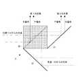
以下、この発明の実施の形態を図1乃至図3に基づいて説明する。図1はこの実施形態の照明装置を示した説明図であり、図2は光路変更の説明図であり、図3は図1の照明装置を二つ組み合わせて成る照明装置を示した説明図である。(Embodiment 1)
Hereinafter, embodiments of the present invention will be described with reference to FIGS. 1 to 3. FIG. 1 is an explanatory diagram showing an illumination device of this embodiment, FIG. 2 is an explanatory diagram of changing an optical path, and FIG. 3 is an explanatory diagram showing an illumination device that is a combination of two illumination devices of FIG. is there.
図1に示す照明装置は、向き合って配置された二つの光源1,1と、これら二つの光源1,1間に配置された3組の光路変更部材2(2A,2B,2C)とから成る。光源1,1はその出射光中心を互いにずらして配置されている。各光源1は、超高圧水銀ランプやメタルハライドランプ等から成る発光部11と、この発光部11から出射された光を略平行光にして出射する放物凹面鏡12とを備える。光路変更部材2Bは光源1の中央領域からの光束を受けるように設けられ、光路変更部材2Aと光路変更部材2Cは光源1の周辺領域からの光束を受けるように設けられている。 The illuminating device shown in FIG. 1 includes two
各光路変更部材2は、入射した略平行光の半分を反射し残り半分を透過させる偏光ビームスプリッタ20と、第1ミラー21と、第2ミラー22とを組み合わせて成る。偏光ビームスプリッタ20の分離膜は光源1の光軸に対して45°傾けて配置され、第1ミラー21は前記分離膜と平行に(前記光軸に対して45°傾けて)配置され、第2ミラー22は第1ミラー21に対して直交する向きに配置されている。各光路変更部材2は二つの光源1A,1Bの位置的に対応する領域からの光束をそれぞれ入射して合成し、当該領域の2倍の領域の光束を形成して一方向(フライアイレンズ3が配置されている方向)に出射することで個々の光源1の出射光を照明対象物であるフライアイレンズ3の全体に導く。 Each optical
具体的には、各光路変更部材2は、一方の光源1Aの所定領域(中央領域又は端部領域)からの光束の半分を偏光ビームスプリッタ20にて前記一方向に反射することで第1の光束を形成し、残り半分の透過した光束を第1ミラー21にて前記一方向に反射することで前記第1の光束に隣り合う第2の光束を形成する。そして、他方の光源1Bから出射され更に第2ミラー22にて前記第1の光束と同方向に導かれた光束の半分を前記偏光ビームスプリッタ20にて透過させて前記第1の光束に重畳し、残り半分の反射された光束を前記第1ミラー21にて前記一方向に反射することで第2の光束に重畳する。 Specifically, each optical
前記偏光ビームスプリッタ20は、光源1からの光の中のP偏光を透過し、S偏光を反射する。従って、図2に示しているように、光源1Aの所定領域からの光束の中のS偏光が第1の光束となり、P偏光が第2の光束となる。一方、光源1Bの所定領域からの光束の中のP偏光が第1の光束となり、S偏光が第2の光束となる。 The polarization beam splitter 20 transmits P-polarized light in the light from the
このように、光源1A,1Bからの光は3つの光路変更部材2A,2B,2Cによって重畳されてフライアイレンズ3上へと導かれることになり、且つ、光源1A,1Bからの出射光のそれぞれをフライアイレンズ3の全体に導くことができる。更に、光路変更部材2Bは光源1A,1Bの中央領域からそれぞれ出射される光束を重畳してフライアイレンズ3の中央領域へと導くことになり、光路変更部材2A,2Cは光源1A,1Bの周辺領域からそれぞれ出射される光束を重畳してフライアイレンズ3の周辺領域へと導くことになる。 In this way, the light from the
隣接する光路変更部材2Aと光路変更部材2Bとにおいて、第2ミラー22と第1ミラー21とが隣り合い、この隣り合うミラー22,21はそれらの縁を合わせて山型に配置されている。また、隣接する光路変更部材2Bと光路変更部材2Cにおいて、第2ミラー22と第1ミラー21とが隣り合い、この隣り合うミラー22,21はそれらの縁を合わせて山型に配置されている。このように山型に配置することでミラー22,21の一体化が可能であり、このように一体化することにより部品点数の削減が図れる。また、フライアイレンズ3のレンズ素子間の谷部に対応して前記偏光ビームスプリッタ20及びミラー21,22の縁を位置させており、当該縁がフライアイレンズ3の凸レンズに対応して位置した場合に生じる不具合を回避している。 In the adjacent optical
図3に示す照明装置は、図1の照明装置(以下、構成要素照明装置と称する)を二つ備え、これら二つの構成要素照明装置間に3つの光路変更部材2A′、2B′、2C′を配置して成る。二つの構成要素照明装置は、その光路変更部材2…による光路変更後の光軸を互いにずらして配置されており、前記フライアイレンズ3は、その光入射面の法線が上記光路変更後の光軸と直交するように配置されている。この図3に示す照明装置は、図1の照明装置を光源として前記光路変更部材2A′、2B′、2C′によって各光源(構成要素照明装置)の光束を重畳する照明装置となり、4灯タイプを実現したものとなる。この図3の照明装置においても、隣接する光路変更部材2A′と光路変更部材2B′において、第2ミラー22′と第1ミラー21′とが隣り合い、この隣り合うミラー22′,21′はそれらの縁を合わせて山型に配置されている。また、隣接する光路変更部材2B′と光路変更部材2C′において、第2ミラー22′と第1ミラー21′とが隣り合い、この隣り合うミラー22′,21′はそれらの縁を合わせて山型に配置されている。また、フライアイレンズ3のレンズ素子間の谷部に対応して前記偏光ビームスプリッタ20′及びミラー21′,22′の縁を位置させている。 The illuminating device shown in FIG. 3 includes two of the illuminating devices of FIG. 1 (hereinafter referred to as component lighting devices), and three optical
(実施の形態2)
以下、この発明の実施形態にかかる投写型映像表示装置を図4に基づいて説明していく。図4は図3の照明装置を用いた液晶プロジェクタを示している。照明装置から出射された白色光は、一対のフライアイレンズ3に照射され、このフライアイレンズ3を経た光は偏光変換装置71に至る。一対のフライアイレンズ3は、対応する個々のレンズ部分が後述する液晶パネルの全面を照射するように設計されており、照明装置から出射された光に存在する部分的な輝度ムラを平均化し、画面中央と周辺部とでの光量差を低減する。(Embodiment 2)
Hereinafter, a projection display apparatus according to an embodiment of the present invention will be described with reference to FIG. FIG. 4 shows a liquid crystal projector using the illumination device of FIG. The white light emitted from the illumination device is applied to the pair of fly-
偏光変換装置71は、偏光ビームスプリッタアレイ(以下、PBSアレイと称する)によって構成されている。PBSアレイは、偏光分離膜と位相差板(1/2λ板)とを備える。PBSアレイの各偏光分離膜は、フライアイレンズ3からの光のうち例えばP偏光を通過させ、S偏光を90°光路変更する。光路偏光されたS偏光は隣接の偏光分離膜にて反射されてそのまま出射される。一方、偏光分離膜を透過したP偏光はその前側(光出射側)に設けてある前記位相差板によってS偏光に変換されて出射される。すなわち、この場合には、ほぼ全ての光はS偏光に変換されるようになっている。 The
偏光変換装置71を経て単一の偏光に変換された光は、集光レンズ72を透過し、全反射ミラー73によって光路を90°変更されて第1ダイクロイックミラー74へと導かれる。第1ダイクロイックミラー74は、赤色波長帯域の光を透過し、シアン(緑+青)の波長帯域の光を反射する。第1ダイクロイックミラー74を透過した赤色波長帯域の光は、全反射ミラー75にて反射されて赤色光用の透過型の液晶パネル81に導かれ、これを透過することで光変調される。一方、第1ダイクロイックミラー74にて反射したシアンの波長帯域の光は、第2ダイクロイックミラー76に導かれる。 The light converted into a single polarized light through the
第2ダイクロイックミラー76は、青色波長帯域の光を透過し、緑色波長帯域の光を反射する。第2ダイクロイックミラー76にて反射した緑色波長帯域の光は、緑色光用の透過型の液晶パネル82に導かれ、これを透過することで光変調される。また、第2ダイクロイックミラー76を透過した青色波長帯域の光は、全反射ミラー77,78を経て青色光用の透過型の液晶パネル83に導かれ、これを透過することで光変調される。 The second
液晶パネル81,82,83を経て得られた変調光(各色映像光)はダイクロイックプリズム79によって合成されてカラー映像光となる。このカラー映像光は、投写レンズ80によって拡大投写され、図示しないスクリーン上に投影表示される。 The modulated light (each color video light) obtained through the
なお、図1や図3の照明装置におけるミラーの縁を合わせて山型に配置することに限らず、三角柱部材を備え、この三角柱部材の互いに隣接する二面を鏡面とすることとしてもよい。二つのミラーの縁を合わせて山型に配置するよりも、三角柱部材を用いた方が作製容易で組立が容易になるという利点がある。また、上記の液晶プロジェクタは図3の照明装置を用いて4灯式としたが、図1の照明装置を用いて2灯式の液晶プロジェクタを構成することもできる。図1の照明装置及び図3の照明装置のいずれについても、各光源からの光を照明対象物であるフライアイレンズ3の全面に導くことができ、従来のストライプ状に導く構成に比べ、複数の光源のうちのどれかが切れた場合の輝度ムラは極めて小さいものとなり、映像投写の続行が良好に行えることになる。また、意図的に幾つかの光源を消灯してエコノミーモードとすることも可能である。 In addition, it is good also as not only arranging the mirror edge in the illuminating device of FIG.1 and FIG.3, but arrange | positioning it in a mountain shape, and providing a triangular prism member and making two adjacent surfaces of this triangular prism member into a mirror surface. Rather than arranging the edges of two mirrors in a mountain shape, the use of a triangular prism member has the advantage that it is easier to manufacture and easier to assemble. In addition, although the above-described liquid crystal projector is a four-lamp type using the lighting device of FIG. 3, a two-lamp type liquid crystal projector can be configured using the lighting device of FIG. In both of the illumination device of FIG. 1 and the illumination device of FIG. 3, light from each light source can be guided to the entire surface of the fly-
また、以上説明した例では、光源の数が2つ及び4つの場合を示したが、複数であればよく、これらの数に限るものではない。対向配置された光源間に3つの光路変更部材を備える構成を示したが、このような3つに限るものではない。対向配置された光源が共に白色光源である場合を示したが、これに限らず、一方を白色光源とし、当該光源の特定波長の光を補うための補助光源(ランプ光源或いは発光ダイオード等を用いた固体素子光源でもよい)を他方の光源とするようにしてもよい。光分離部材として偏光ビームスプリッタを示したが、ハーフミラーを用いてもよい。投写型映像表示装置として3板式の液晶プロジェクタを示したが、単板式の液晶プロジェクタでもよい。更に、液晶パネル以外のライトバルブを用いた構成でもよい。 Moreover, although the case where the number of the light sources was two and four was shown in the example demonstrated above, what is necessary is just two or more, and it does not restrict to these numbers. Although the configuration in which three optical path changing members are provided between the light sources arranged to face each other is shown, the configuration is not limited to such three. The case where both of the opposed light sources are white light sources has been shown. However, the present invention is not limited to this, and one of the light sources is a white light source, and an auxiliary light source (a lamp light source or a light emitting diode) is used to supplement light of a specific wavelength of the light source. The other solid-state light source may be used as the other light source. Although a polarizing beam splitter is shown as the light separating member, a half mirror may be used. Although a three-plate type liquid crystal projector has been shown as the projection display apparatus, a single-plate type liquid crystal projector may be used. Furthermore, the structure using light valves other than a liquid crystal panel may be sufficient.
1(1A,1B) 光源
2(2A,2B,2C) 光路変更部材
2′(2A′,2B′,2C′) 光路変更部材
20 偏光ビームスプリッタ
21 第1ミラー
22 第2ミラー
3 フライアイレンズ1 (1A, 1B) Light source 2 (2A, 2B, 2C) Optical path changing member 2 '(2A', 2B ', 2C') Optical
Claims (7)
Translated fromJapanesePriority Applications (4)
| Application Number | Priority Date | Filing Date | Title |
|---|---|---|---|
| JP2003401011AJP4514440B2 (en) | 2003-12-01 | 2003-12-01 | Projection display device |
| US10/998,969US7195373B2 (en) | 2003-12-01 | 2004-11-30 | Illuminating device and projection type video display |
| CNB2004101000132ACN100416402C (en) | 2003-12-01 | 2004-11-30 | Illuminating device and projection type video display |
| EP04257456.6AEP1538832B1 (en) | 2003-12-01 | 2004-12-01 | Illuminating device and projection type video display |
Applications Claiming Priority (1)
| Application Number | Priority Date | Filing Date | Title |
|---|---|---|---|
| JP2003401011AJP4514440B2 (en) | 2003-12-01 | 2003-12-01 | Projection display device |
Publications (2)
| Publication Number | Publication Date |
|---|---|
| JP2005164769A JP2005164769A (en) | 2005-06-23 |
| JP4514440B2true JP4514440B2 (en) | 2010-07-28 |
Family
ID=34463918
Family Applications (1)
| Application Number | Title | Priority Date | Filing Date |
|---|---|---|---|
| JP2003401011AExpired - Fee RelatedJP4514440B2 (en) | 2003-12-01 | 2003-12-01 | Projection display device |
Country Status (4)
| Country | Link |
|---|---|
| US (1) | US7195373B2 (en) |
| EP (1) | EP1538832B1 (en) |
| JP (1) | JP4514440B2 (en) |
| CN (1) | CN100416402C (en) |
Families Citing this family (25)
| Publication number | Priority date | Publication date | Assignee | Title |
|---|---|---|---|---|
| JP2007537461A (en)* | 2004-03-11 | 2007-12-20 | トムソン ライセンシング | Multiple lamp illumination system with polarization recovery and integration |
| GB2425615B (en)* | 2005-04-27 | 2009-02-18 | Michael John Hanney | Colour mixing optic |
| TW200641509A (en)* | 2005-05-19 | 2006-12-01 | Coretronic Corp | Auxiliary device suitable for realizing reciprocally modularization with projection apparatus |
| JP2007163619A (en)* | 2005-12-12 | 2007-06-28 | Hitachi Ltd | Illumination optical unit, projection display device using the same, and image display method |
| JP2007322584A (en)* | 2006-05-31 | 2007-12-13 | Sanyo Electric Co Ltd | Lighting device and projection type video display device using the same |
| JP5156338B2 (en)* | 2007-06-27 | 2013-03-06 | 三洋電機株式会社 | LIGHTING DEVICE AND PROJECTION VIDEO DISPLAY DEVICE USING THE SAME |
| JP5489405B2 (en)* | 2007-11-26 | 2014-05-14 | 株式会社リコー | Projection display |
| JP5180677B2 (en)* | 2008-05-14 | 2013-04-10 | 三洋電機株式会社 | Illumination device and projection-type image display device using the same |
| US8459830B2 (en)* | 2008-06-10 | 2013-06-11 | Koninklijke Philips Electronics N.V. | Light output device with partly transparent mirror |
| US8235536B2 (en) | 2008-11-06 | 2012-08-07 | Projectiondesign As | High intensity image projector using sectional mirror |
| JP4516622B2 (en)* | 2008-12-08 | 2010-08-04 | 三菱電機株式会社 | Projection display |
| JP5483955B2 (en)* | 2009-08-20 | 2014-05-07 | キヤノン株式会社 | Illumination optical system and projection display device |
| JP5517597B2 (en)* | 2009-12-21 | 2014-06-11 | キヤノン株式会社 | Illumination optical system and projection display device |
| JP5842167B2 (en)* | 2011-02-28 | 2016-01-13 | パナソニックIpマネジメント株式会社 | Light source device and projection display device |
| TWI447435B (en)* | 2011-04-29 | 2014-08-01 | Delta Electronics Inc | Light source system |
| CN103207509B (en)* | 2012-01-12 | 2015-06-24 | 三菱电机株式会社 | Light Source Device And Projecting Display Device |
| US8998447B2 (en) | 2012-09-26 | 2015-04-07 | Projectdesign As | Illumination devices using array of reflectors |
| TWI512334B (en)* | 2013-11-28 | 2015-12-11 | Delta Electronics Inc | Light source system and display apparatus comprising the same |
| CN104460204B (en)* | 2014-11-14 | 2016-09-07 | 苏州佳世达光电有限公司 | Projection arrangement |
| US9977319B2 (en) | 2015-12-18 | 2018-05-22 | Casio Computer Co., Ltd. | Light source device with light splitting mirror and reflection mirror for reducing influence on uniformity of intensity distribution of beam flux, and projection device |
| JP6414706B2 (en)* | 2015-12-18 | 2018-10-31 | カシオ計算機株式会社 | Light source device and projection device |
| CN113391506B (en)* | 2020-03-12 | 2022-12-06 | 中强光电股份有限公司 | Illumination system and projection device |
| US12332559B2 (en)* | 2020-03-12 | 2025-06-17 | Coretronic Corporation | Illumination system and projection apparatus |
| CN113391507B (en) | 2020-03-13 | 2022-07-19 | 中强光电股份有限公司 | Light source module and projection device |
| CN113589635B (en) | 2020-04-30 | 2023-03-31 | 中强光电股份有限公司 | Illumination system and projection device |
Family Cites Families (13)
| Publication number | Priority date | Publication date | Assignee | Title |
|---|---|---|---|---|
| US5719704A (en)* | 1991-09-11 | 1998-02-17 | Nikon Corporation | Projection exposure apparatus |
| JPH05181089A (en)* | 1992-01-07 | 1993-07-23 | Canon Inc | Polarized light illuminator and projection display device using the same |
| US5903388A (en)* | 1992-06-11 | 1999-05-11 | Sedlmayr Steven R | High efficiency electromagnetic beam projector and systems and method for implementation thereof |
| JP3272078B2 (en)* | 1993-01-11 | 2002-04-08 | 三洋電機株式会社 | Light source device |
| JPH07225430A (en) | 1994-02-14 | 1995-08-22 | Japan Aviation Electron Ind Ltd | Light source device for projector |
| US5504544A (en)* | 1994-11-23 | 1996-04-02 | Minnesota Mining And Manufacturing Company | Projector with multiple lamp light source |
| JPH0996786A (en)* | 1995-09-29 | 1997-04-08 | Matsushita Electric Ind Co Ltd | Projection display device |
| US6109752A (en)* | 1996-08-26 | 2000-08-29 | Seiko Epson Corporation | Lighting device and projector |
| US6243152B1 (en)* | 1996-12-17 | 2001-06-05 | Duke University | Contrast polymer dispersed liquid crystal projection display system |
| JP3661392B2 (en)* | 1998-02-18 | 2005-06-15 | セイコーエプソン株式会社 | Polarized illumination device and projection display device |
| JP3408202B2 (en)* | 1999-07-06 | 2003-05-19 | 三洋電機株式会社 | Illumination device and projection type video display device |
| JP3821622B2 (en)* | 1999-12-08 | 2006-09-13 | シャープ株式会社 | Projection display |
| JP2002341291A (en)* | 2001-05-16 | 2002-11-27 | Nagano Kogaku Kenkyusho:Kk | Polarized light source device |
- 2003
- 2003-12-01JPJP2003401011Apatent/JP4514440B2/ennot_activeExpired - Fee Related
- 2004
- 2004-11-30CNCNB2004101000132Apatent/CN100416402C/ennot_activeExpired - Fee Related
- 2004-11-30USUS10/998,969patent/US7195373B2/ennot_activeExpired - Fee Related
- 2004-12-01EPEP04257456.6Apatent/EP1538832B1/ennot_activeExpired - Lifetime
Also Published As
| Publication number | Publication date |
|---|---|
| EP1538832A2 (en) | 2005-06-08 |
| JP2005164769A (en) | 2005-06-23 |
| EP1538832B1 (en) | 2013-07-10 |
| US20050117337A1 (en) | 2005-06-02 |
| CN100416402C (en) | 2008-09-03 |
| EP1538832A3 (en) | 2006-06-28 |
| CN1624575A (en) | 2005-06-08 |
| US7195373B2 (en) | 2007-03-27 |
Similar Documents
| Publication | Publication Date | Title |
|---|---|---|
| JP4514440B2 (en) | Projection display device | |
| JP5156338B2 (en) | LIGHTING DEVICE AND PROJECTION VIDEO DISPLAY DEVICE USING THE SAME | |
| CN100383660C (en) | Illumination device and projection type image display | |
| US20060232750A1 (en) | Optical member and illuminating device | |
| JP2009265120A (en) | Projection type display device | |
| JP2006145644A (en) | Polarization separator and projection display device using the same | |
| CN100567805C (en) | Lighting device and projection type image display | |
| JP2007322584A (en) | Lighting device and projection type video display device using the same | |
| JP4162484B2 (en) | Projection display device | |
| US6987618B2 (en) | Polarization converting device, illumination optical system and projector | |
| JP2009086057A (en) | Projection display device | |
| US20040227899A1 (en) | Video light producing device and projection type video display | |
| JP2000193926A (en) | Light source unit, illumination optical system, and projection display device | |
| JP2006317925A (en) | Optical member, illumination device, and projection type video display apparatus | |
| WO2005114319A1 (en) | Projector | |
| JP3893872B2 (en) | Polarization conversion element and projector | |
| JP3510849B2 (en) | Projection type video display | |
| JP2008203467A (en) | Optical element, illumination device and projection type image display apparatus | |
| JP4097512B2 (en) | Projection display device | |
| JP2005165137A (en) | Illumination optical system and image display device | |
| JP4115420B2 (en) | Illumination device and projection display device | |
| JP2004061848A (en) | Illumination optics and projector | |
| JP2008158274A (en) | projector | |
| JP2010113266A (en) | Projection display device | |
| JP2008089889A (en) | Projection type video display apparatus |
Legal Events
| Date | Code | Title | Description |
|---|---|---|---|
| A621 | Written request for application examination | Free format text:JAPANESE INTERMEDIATE CODE: A621 Effective date:20060831 | |
| A977 | Report on retrieval | Free format text:JAPANESE INTERMEDIATE CODE: A971007 Effective date:20100126 | |
| A131 | Notification of reasons for refusal | Free format text:JAPANESE INTERMEDIATE CODE: A131 Effective date:20100202 | |
| A521 | Request for written amendment filed | Free format text:JAPANESE INTERMEDIATE CODE: A523 Effective date:20100326 | |
| TRDD | Decision of grant or rejection written | ||
| A01 | Written decision to grant a patent or to grant a registration (utility model) | Free format text:JAPANESE INTERMEDIATE CODE: A01 Effective date:20100413 | |
| A01 | Written decision to grant a patent or to grant a registration (utility model) | Free format text:JAPANESE INTERMEDIATE CODE: A01 | |
| A61 | First payment of annual fees (during grant procedure) | Free format text:JAPANESE INTERMEDIATE CODE: A61 Effective date:20100511 | |
| FPAY | Renewal fee payment (event date is renewal date of database) | Free format text:PAYMENT UNTIL: 20130521 Year of fee payment:3 | |
| FPAY | Renewal fee payment (event date is renewal date of database) | Free format text:PAYMENT UNTIL: 20130521 Year of fee payment:3 | |
| FPAY | Renewal fee payment (event date is renewal date of database) | Free format text:PAYMENT UNTIL: 20140521 Year of fee payment:4 | |
| LAPS | Cancellation because of no payment of annual fees |