JP4511668B2 - Continuously variable transmission for vehicle - Google Patents
Continuously variable transmission for vehicleDownload PDFInfo
- Publication number
- JP4511668B2 JP4511668B2JP2000030223AJP2000030223AJP4511668B2JP 4511668 B2JP4511668 B2JP 4511668B2JP 2000030223 AJP2000030223 AJP 2000030223AJP 2000030223 AJP2000030223 AJP 2000030223AJP 4511668 B2JP4511668 B2JP 4511668B2
- Authority
- JP
- Japan
- Prior art keywords
- transmission
- rotating member
- transmission shaft
- driven
- carrier
- Prior art date
- Legal status (The legal status is an assumption and is not a legal conclusion. Google has not performed a legal analysis and makes no representation as to the accuracy of the status listed.)
- Expired - Fee Related
Links
Images

Classifications
- F—MECHANICAL ENGINEERING; LIGHTING; HEATING; WEAPONS; BLASTING
- F16—ENGINEERING ELEMENTS AND UNITS; GENERAL MEASURES FOR PRODUCING AND MAINTAINING EFFECTIVE FUNCTIONING OF MACHINES OR INSTALLATIONS; THERMAL INSULATION IN GENERAL
- F16H—GEARING
- F16H15/00—Gearings for conveying rotary motion with variable gear ratio, or for reversing rotary motion, by friction between rotary members
- F16H15/02—Gearings for conveying rotary motion with variable gear ratio, or for reversing rotary motion, by friction between rotary members without members having orbital motion
- F16H15/04—Gearings providing a continuous range of gear ratios
- F16H15/06—Gearings providing a continuous range of gear ratios in which a member A of uniform effective diameter mounted on a shaft may co-operate with different parts of a member B
- F16H15/16—Gearings providing a continuous range of gear ratios in which a member A of uniform effective diameter mounted on a shaft may co-operate with different parts of a member B in which the member B has a conical friction surface
- F16H15/18—Gearings providing a continuous range of gear ratios in which a member A of uniform effective diameter mounted on a shaft may co-operate with different parts of a member B in which the member B has a conical friction surface externally
Landscapes
- Engineering & Computer Science (AREA)
- General Engineering & Computer Science (AREA)
- Mechanical Engineering (AREA)
- Friction Gearing (AREA)
- Control Of Transmission Device (AREA)
- Transmission Devices (AREA)
Description
Translated fromJapanese【0001】
【発明の属する技術分野】
本発明は、駆動回転部材および従動回転部材に摩擦接触する変速回転部材を支承するキャリアの移動により、駆動回転部材から従動回転部材への変速可能な動力伝達を行なう車両用無段変速機に関する。
【0002】
【従来の技術】
従来、かかる車両用無段変速機は、たとえば特開平10−184841号公報等で既に知られている。
【0003】
【発明が解決しようとする課題】
ところで、このような無段変速機では、自動二輪車等の車両を押して移動させるときに無段変速機の各部摩擦力に打勝つ大きな力で押すことを不要とし、軽い力で押すだけで自動二輪車等の車両を移動させることができるようにする必要があり、上記従来のものでは、従動回転部材に連なる出力ギヤと、駆動輪に連なる出力軸との間に、動力伝達・遮断を切換えるニュートラルクラッチが設けられている。すなわち無段変速機および駆動輪間の動力伝達・遮断を切換える機構が無段変速機とは別に必要であり、部品点数が多くなるとともにコストの増大を招いている。
【0004】
本発明は、かかる事情に鑑みてなされたものであり、無段変速機以外の機構を不要として、車両を軽い力で押し動かし得るようにした車両用無段変速機を提供することを目的とする。
【0005】
【課題を解決するための手段】
上記目的を達成するために、請求項1記載の発明は、エンジンからの動力伝達に応じて回転する変速機軸と、該変速機軸とともに回転する駆動回転部材と、前記変速機軸に回転自在に支承される従動回転部材と、前記変速機軸の軸線に沿って移動可能なキャリアと、前記変速機軸の軸線を中心線とする円錐母線に沿う軸線を有して前記キャリアに支持される支軸と、前記駆動回転部材に摩擦接触する円錐状の第1摩擦伝達面および前記従動回転部材に摩擦接触する円錐状の第2摩擦伝達面を有して前記支軸で回転自在かつ軸方向摺動自在に支承される変速回転部材と、前記キャリアがロー変速比の位置からトップ変速比とは反対側に移動するのに応じて前記従動回転部材と第2摩擦伝達面との摩擦接触を解除し得る動力遮断手段とを備える車両用無段変速機であって、前記従動回転部材が、前記変速機軸の軸線方向に制限された範囲での移動を可能として該変速機軸に回転自在に支承されるとともに前記第2摩擦伝達面に摩擦接触する方向にばね付勢され、前記動力遮断手段であるスラストベアリングが、ロー変速比の位置からトップ変速比とは反対側への前記キャリアの移動に応じて前記従動回転部材を変速機軸の軸線方向に押圧駆動することを可能として前記キャリアの内周部に装着されることを特徴とする。
【0006】
このような構成によれば、動力遮断手段により従動回転部材および第2摩擦伝達面の摩擦接触を解除することにより、無段変速機を動力遮断状態とし、軽い力で押すだけで自動二輪車等の車両を移動させることができ、しかも動力遮断手段は、無段変速機を構成する従動回転部材を変速機軸の軸線方向に駆動するものであり、無段変速機とは別の機構であるニュートラルクラッチを必要とした従来のものと比べると、部品点数の低減およびコスト低減を図ることができる。
【0007】
その上、無段変速機をキャリアの位置に関連させた単純な構造で動力遮断状態とすることができるため、キャリアを駆動する駆動源以外に動力遮断手段を作動せしめる特別の動力は不要であり、しかもエンジンおよび駆動輪間の動力伝達を遮断するニュートラル状態を、ロー変速比の位置からのキャリアのトップ変速比とは反対側への移動に応じて得るようにしたので、ロー変速比の状態からニュートラル状態に変化させるための構造を単純化することが可能である。
【0008】
また特に従動回転部材が、変速機軸の軸線方向に制限された範囲での移動を可能として該変速機軸に回転自在に支承されるとともに第2摩擦伝達面に摩擦接触する方向にばね付勢され、前記動力遮断手段であるスラストベアリングが、ロー変速比の位置からトップ変速比とは反対側へのキャリアの移動に応じて従動回転部材を変速機軸の軸線方向に押圧駆動することを可能としてキャリアの内周部に装着されるので、従動回転部材およびキャリア間で摩擦力が生じることを極力抑えつつ、従動回転部材を駆動回転部材から離間する方向に駆動することができ、しかもキャリアの内周部での周速度は小さいのでスラストベアリングに作用する負荷を小さく抑えることができる。
【0009】
さらに請求項2記載の発明は、上記請求項1記載の発明の構成に加えて、前記従動回転部材と、前記変速機軸の軸線方向に沿う位置を不変として該変速機軸の軸線まわりに回転自在である第2の回転部材との間に、前記駆動回転部材および前記従動回転部材を前記第1および第2摩擦伝達面に圧接させる面圧を発生しつつ前記従動回転部材および第2の回転部材間で動力を伝達する調圧カム機構が設けられ、前記従動回転部材と第2摩擦伝達面との摩擦接触を解除する位置への前記従動回転部材の移動が該調圧カム機構で吸収されることを特徴とし、かかる構成によれば、動力伝達状態では駆動回転部材および前記従動回転部材と第1および第2摩擦伝達面との確実な摩擦接触を確保しつつ、動力遮断時に従動回転部材が軸方向に移動することを許容することができる。
【0010】
【発明の実施の形態】
以下、本発明の実施形態を、添付図面に示した本発明の一実施例に基づいて説明する。
【0011】
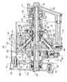
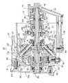
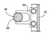
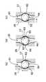
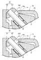
図1〜図6は本発明の一実施例を示すものであり、図1はエンジンおよび無段変速機間の動力伝達構造を示す縦断面図、図2はロー変速比の状態での無段変速機の拡大縦断面図、図3はトップ変速比の状態での無段変速機の拡大縦断面図、図4は図1の4−4線拡大断面図、図5は調圧カム機構の作動状況を説明するための断面図、図6は図2の6矢示部拡大図である。
【0012】
先ず図1において、自動二輪車等の車両に搭載されるエンジンEの出力は、該エンジンEのクランクシャフト11からドライブギヤ12、ドリブンギヤ13、ダンパばね14、自動遠心クラッチ15および無段変速機16を介して出力ギヤ17に伝達されるものであり、駆動輪である後輪WRに連なる減速ギヤ18が前記出力ギヤ17に噛合される。
【0013】
前記ドライブギヤ12、ドリブンギヤ13、ダンパばね14および自動遠心クラッチ15は、前記エンジンEのクランクケースに結合されるケーシング19内に形成される第1作動室20に収納され、前記無段変速機16、出力ギヤ17および減速ギヤ18は、前記ケーシング19内に形成される第2作動室21に収納され、第1および第2作動室20,21は、ケーシング19に設けられる壁部19aの両側でケーシング19内に形成される。
【0014】
第1作動室20内にはクランクシャフト11と平行な軸線を有する入力軸22が配置され、入力軸22の両端部はケーシング19で回転自在に支承される。自動遠心クラッチ15は、前記ドリブンギヤ13にダンパばね14を介して連結されるとともに入力軸22で回転自在に支承される入力部材23と、入力軸22に結合される椀状の出力部材24と、該出力部材24の内面に摩擦接触することを可能として入力部材23に揺動可能に支承される複数の遠心ウエイト25…と、前記出力部材24との摩擦接触を解除する方向に各遠心ウエイト25…をばね付勢するばね(図示せず)とを備える従来周知のものであり、エンジンEから入力部材23に動力が伝達されることによって入力部材23の回転数が所定値以上となったときに入力部材23から出力部材24すなわち入力軸22に動力を伝達する。
【0015】
図2および図3を併せて参照して、無段変速機16は、前記入力軸22と同軸の軸線を有する変速機軸26と、該変速機軸26と一体に回転する駆動回転部材27と、変速機軸26に相対回転自在に支承される従動回転部材28と、変速機軸26の軸線に沿って移動可能なキャリア29と、該キャリア29に支持される複数の支軸30,30…と、それらの支軸30,30…でそれぞれ支承される変速回転部材31,31…とを備える。
【0016】
変速機軸26の一端はケーシング19の壁部19aを液密にかつ回転自在に貫通して第1作動室20に突入されており、入力軸22に相対回転不能に結合される。駆動回転部材27は半径方向外方に向く摩擦接触面27aを有してリング状に形成されるものであり、圧入等により変速機軸26に相対回転不能に結合される。また従動回転部材28は駆動回転部材27側に開放した椀状に形成されるとともにニードルベアリング32を介して前記変速機軸26に相対回転自在に支承されるものであり、この従動回転部材28の開放端内面に半径方向内方に向く摩擦接触面28aが設けられる。
【0017】
キャリア29は、従動回転部材28側を小径とした略円錐状の第1キャリア半体33と、円板状に形成されるとともに第1キャリア半体33の大径端側すなわち従動回転部材28とは反対側の端部に結合される第2キャリア半体34とから成るものであり、第1および第2キャリア半体33,34はニードルベアリング35,36を介して変速機軸26に相対回転自在かつ軸方向摺動可能に支承される。
【0018】
第1キャリア半体33には、その周方向に等間隔をあけた複数の窓孔37…が設けられており、変速機軸26の軸線を中心線とする円錐母線に沿う軸線を有して前記各窓孔37…を横切る複数の支軸30…の両端が第1キャリア半体33に支持される。これらの支軸30…には、一対のニードルベアリング38,38…をそれぞれ介して各変速回転部材31…が回転可能かつ軸方向摺動可能に支承される。
【0019】
変速回転部材31には、駆動回転部材27の摩擦接触面27aに摩擦接触する円錐状の第1摩擦伝達面40と、従動回転部材28の摩擦接触面28aに摩擦接触する円錐状の第2摩擦伝達面41とが設けられる。
【0020】
図4を併せて参照して、キャリア29の第2キャリア半体34における外周には、変速機軸26の軸線と直交する軸線を有する軸42が固定されており、この軸42でローラ43が回転自在に支承される。一方、ケーシング19の内面には、変速機軸26の軸線と平行な方向に延びるU字状の規制部材44が締結されており、前記ローラ43は該規制部材44内に転動可能に収容される。したがって第2キャリア半体34すなわちキャリア29は、変速機軸26の軸線方向の移動を可能とするとともに変速機軸26の軸線まわりの回転を不能としてケーシング19に係合されることになる。
【0021】
キャリア29の第2キャリア半体34には変速機軸26と同軸である被動ねじ45が締結され、この被動ねじ45には、変速機軸26にボールベアリング56を介して回転自在に支承される駆動ねじ46が螺合される。
【0022】
ケーシング19の外面には、変速機軸26と平行な軸線を有する正・逆回転自在な電動モータ47が取付けられており、この電動モータ47および前記駆動ねじ46間に減速機構48が設けられる。
【0023】
該減速機構48は、電動モータ47の出力軸に設けられる駆動ギヤ49と、該駆動ギヤ49に噛合する第1アイドルギヤ50と、第1アイドルギヤ50と一体である第2アイドルギヤ51と、駆動ねじ46に固着されて第2アイドルギヤ51に噛合する被動ギヤ52とから成るものであり、第1および第2アイドルギヤ50,51は変速機軸26と平行な軸線を有してケーシング19に支持されるアイドル軸53で回転自在に支承される。
【0024】
電動モータ47から減速機構48を介して駆動ねじ46に回転動力が与えられると、該駆動ねじ46に螺合した被動ねじ45が固定されているキャリア29が、変速機軸26の軸線方向の移動を可能とするとともに変速機軸26の軸線まわりの回転を不能としてケーシング19に係合されているので、変速機軸26の軸線方向に移動することになる。
【0025】
このような無段変速機16において、駆動回転部材27の摩擦接触面27aおよび第1摩擦伝達面40の接触点から変速機軸26の軸線までの距離をA、駆動回転部材27の摩擦接触面27aおよび第1摩擦伝達面40の接触点から支軸30の軸線までの距離をB、従動回転部材28の摩擦接触面28aおよび第2摩擦伝達面41の接触点から支軸30の軸線までの距離をC、従動回転部材28の摩擦接触面28aおよび第2摩擦伝達面41の接触点から変速機軸26の軸線までの距離をDとし、駆動回転部材27の回転数をNI、従動回転部材28の回転数をNOとし、変速比RをR=NI/NOとしたときに、
R=NI/NO=(B/A)×(D/C)
となる。
【0026】
而して電動モータ47および減速機構48により駆動ねじ46を回転せしめ、被動ねじ45およびキャリア29を、図2で示すように、従動回転部材28に近接する方向に移動させると、距離Bが大きくなるとともに距離Cが小さくなり、距離A,Dは一定であるので変速比Rが大きくなり、距離Bが最大となるとともに距離Cが最小となった図2の状態でロー変速比となる。一方、被動ねじ45およびキャリア29を、図3で示すように、従動回転部材28から離反する方向に移動させると、距離Bが小さくなるとともに距離Cが大きくなり、距離A,Dは一定であるので変速比Rが小さくなり、距離Bが最小となるとともに距離Cが最大となった図3の状態でトップ変速比となる。
【0027】
前記減速機構48における被動ギヤ52には、ケーシング19の壁部19a側に向けて突出する規制突部54が一体に突設される。また前記壁部19aには、規制突部54に当接、係合可能なストッパ55が固定されており、規制突部54がストッパ55に当接、係合することにより駆動ねじ46の回転角度すなわちキャリア29の軸方向移動量が規制される。
【0028】
従動回転部材28に関してキャリア29とは反対側には、変速機軸26を同軸に囲繞する出力ギヤ17が配置されており、この出力ギヤ17の内周および変速機軸26間にはアンギュラーコンタクトベアリング57が介装される。該アンギュラーコンタクトベアリング57の外輪は、出力ギヤ17と、該出力ギヤ17の内周に装着される止め輪58とで挟まれる。またアンギュラーコンタクトベアリング57の内輪において従動回転部材28とは反対側の端部には、変速機軸26を同軸に囲繞して出力ギヤ17および変速機軸26間に挿入される円筒状のスペーサ59の一端が当接されており、該スペーサ59の他端は変速機軸26に装着される止め輪60に当接される。したがって出力ギヤ17は、従動回転部材28から離反する方向の移動を阻止されて変速機軸26に回転自在に支承されることになる。一方、従動回転部材28および出力ギヤ17間には、従動回転部材28に出力ギヤ17から離反する方向の予荷重を与える皿ばね65が介装されており、変速機軸26の軸線方向に沿う出力ギヤ17の位置は実質的に一定に定められることになる。
【0029】
前記従動回転部材28と、第2の回転部材としての前記出力ギヤ17との間には調圧カム機構61が設けられる。この調圧カム機構61は、従動回転部材28および出力ギヤ17の対向面にそれぞれ複数ずつ設けられた凹部62…,63…間にボール64…が挟持されて成るものである。而して従動回転部材28にトルクが作用して出力ギヤ17との間に相対回転が生じると、図5(a)で示すように、調圧カム機構61は、従動回転部材28を出力ギヤ17から離反させる方向に付勢しつつ従動回転部材28から出力ギヤ17に回転動力を伝達する。この付勢力は前記皿ばね65による付勢力と共働して、駆動回転部材27の摩擦接触面27aを第1摩擦伝達面40に圧接する面圧ならびに従動回転部材28の摩擦接触面28aを第2摩擦伝達面41に圧接する面圧を発生させる。
【0030】
また従動回転部材28にトルクが作用せず、出力ギヤ17との間に相対回転が生じていない中立状態では、図5(b)で示すように、ボール64と両凹部62,63との間には間隙66,66が生じており、図5(c)で示すように、従動回転部材28は前記間隙66,66をなくすように出力ギヤ17側にたとえば0.5mm程度移動することができる。
【0031】
キャリア29における第1キャリア半体33の内周部には、動力遮断手段としてのスラストベアリング70が装着されており、このスラストベアリング70は、ロー変速比の位置からトップ変速比とは反対側にキャリア29が移動するのに応じて従動回転部材28を駆動回転部材27から離間する側に押圧駆動し得るようにして装着される。
【0032】
すなわちスラストベアリング70は、キャリア29が図2で示すロー変速比の位置にある状態では、従動回転部材28とは接触しない状態、もしくは接触していても従動回転部材28に押圧力を作用していない状態にあるのであるが、キャリア29がロー変速比の位置からトップ変速比とは反対側すなわち図2の右側に移動するのに応じて、調圧カム機構61で許容される範囲で従動回転部材28を押圧駆動するようにしてキャリア29の内周部に装着される。
【0033】
而してロー変速比の状態では、図6(a)で示すように、変速回転部材31の第2摩擦伝達面41が従動回転部材28の摩擦接触面28aに摩擦接触した状態にあるが、キャリア29がロー変速比の位置からトップ変速比とは反対側に移動するのに応じた従動回転部材28の移動により、図6(b)で示すように、変速回転部材31の第2摩擦伝達面41と従動回転部材28の摩擦接触面28aとの摩擦接触が解除される。
【0034】
変速機軸16の他端側はボールベアリング72を介してケーシング19に回転自在に支承されており、該変速機軸16の他端には、トロコイドポンプであるオイルポンプ71が連結される。一方、第2作動室21内の下部に臨むフィルタ74がケーシング19に取付けられており、ケーシング19には、フィルタ74およびオイルポンプ71間を結ぶ吸入油路73が設けられ、変速機軸26には、オイルポンプ71からのオイルを導く潤滑油路75が同軸に設けられるとともに、内端を潤滑油路75に連通せしめるとともに外端を変速機軸26の外面に開口せしめた複数の給油孔76…が無段変速機16に対応して設けられる。
【0035】
また第1作動室20内の下部に対応してケーシング19には他のフィルタ77が取付けられており、このフィルタ77で浄化されたオイルは、図示しない他のオイルポンプにより、ケーシング19に設けられた吸入油路78を経てエンジンEの各潤滑部に供給される。
【0036】
次にこの実施例の作用について説明すると、無段変速機16におけるキャリア29に装着されるスラストベアリング70は、従動回転部材28および第2摩擦伝達面41の摩擦接触を解除することが可能であり、その摩擦接触の解除により無段変速機16が動力遮断状態とされ、出力ギヤ17を無段変速機16での摩擦力の作用を回避して自由に回転させることができので、軽い力で押すだけで自動二輪車等の車両を移動させることができる。
【0037】
しかもスラストベアリング70は、無段変速機16の一部を構成する従動回転部材28を変速機軸26の軸線方向に駆動するものであり、無段変速機16とは別の機構であるニュートラルクラッチを必要とした従来のものと比べると、部品点数の低減およびコスト低減を図ることができる。
【0038】
またスラストベアリング70は、キャリア29がロー変速比の位置からトップ変速比とは反対側に移動するのに応じて前記従動回転部材28を変速機軸26の軸線方向に駆動するものであるので、キャリア29の位置に関連させた単純な構造で無段変速機16を動力遮断状態とすることができ、キャリア29を駆動する電動モータ47以外にスラストベアリング70を作動せしめる特別の動力は不要である。しかもエンジンEおよび後輪WR間の動力伝達を遮断するニュートラル状態を、ロー変速比の位置からのキャリア29のトップ変速比とは反対側への移動に応じて得るようにしたので、ロー変速比の状態からニュートラル状態に変化させるための構造を単純化することが可能である。
【0039】
またスラストベアリング70で従動回転部材28を押圧駆動するので、従動回転部材28およびキャリア29間で摩擦力が生じることを極力抑えつつ従動回転部材28を駆動回転部材27から離間する方向に駆動することができる。またスラストベアリング70がキャリア29の内周部に装着されており、キャリア29の内周部での周速度は小さいのでスラストベアリング70に作用する負荷を小さく抑えることができる。
【0040】
さらに従動回転部材28と、変速機軸26の軸線方向に沿う位置を不変として該変速機軸26の軸線まわりに回転自在である出力ギヤ17との間に、駆動回転部材27および従動回転部材28を第1および第2摩擦伝達面40,41に圧接させる面圧を発生しつつ従動回転部材28および出力ギヤ17間で動力を伝達する調圧カム機構61が設けられており、従動回転部材28と第2摩擦伝達面41との摩擦接触を解除する位置への従動回転部材28の移動が該調圧カム機構61で吸収される。したがって動力伝達状態では駆動回転部材27および従動回転部材28と第1および第2摩擦伝達面40,41との確実な摩擦接触を確保しつつ、動力遮断時に従動回転部材28が軸方向に移動することを許容することができる。
【0041】
以上、本発明の実施例を説明したが、本発明は上記実施例に限定されるものではなく、特許請求の範囲に記載された本発明を逸脱することなく種々の設計変更を行うことが可能である。
【0042】
【発明の効果】
以上のように本発明によれば、部品点数の低減およびコスト低減を図りつつ、軽い力で押すだけで自動二輪車等の車両を移動させることができる。しかも無段変速機をキャリアの位置に関連させた単純な構造で動力遮断状態とすることができるから、キャリアを駆動する駆動源以外に動力遮断手段を作動せしめる特別の動力が不要となり、ロー変速比の状態からニュートラル状態に変化させるための構造を単純化することが可能である。その上、従動回転部材およびキャリア間で摩擦力が生じることを極力抑えつつ、従動回転部材を駆動回転部材から離間する方向に駆動することができ、スラストベアリングに作用する負荷も小さく抑えることができる。
【0043】
さらに請求項2の発明によれば、動力伝達状態では駆動回転部材および従動回転部材と第1および第2摩擦伝達面との確実な摩擦接触を確保しつつ、動力遮断時に従動回転部材が軸方向に移動することを許容することができる。
【図面の簡単な説明】
【図1】 エンジンおよび無段変速機間の動力伝達構造を示す縦断面図である。
【図2】 ロー変速比の状態での無段変速機の拡大縦断面図である。
【図3】 トップ変速比の状態での無段変速機の拡大縦断面図である。
【図4】 図1の4−4線拡大断面図である。
【図5】 調圧カム機構の作動状況を説明するための断面図である。
【図6】 図2の6矢示部拡大図である。
【符号の説明】
16・・・無段変速機
17・・・第2の回転部材としての出力ギヤ
26・・・変速機軸
27・・・駆動回転部材
28・・・従動回転部材
29・・・キャリア
30・・・支軸
31・・・変速回転部材
40・・・第1摩擦伝達面
41・・・第2摩擦伝達面
61・・・調圧カム機構
70・・・動力遮断手段としてのスラストベアリング
E・・・・エンジン[0001]
BACKGROUND OF THE INVENTION
The present invention relates to a continuously variable transmission for a vehicle that performs variable transmission of power from a drive rotary member to a driven rotary member by movement of a carrier that supports a variable speed rotary member that frictionally contacts the drive rotary member and the driven rotary member.
[0002]
[Prior art]
Conventionally, such a continuously variable transmission for a vehicle is already known, for example, in JP-A-10-184841.
[0003]
[Problems to be solved by the invention]
By the way, in such a continuously variable transmission, when a vehicle such as a motorcycle is pushed and moved, it is not necessary to press with a large force to overcome the frictional force of each part of the continuously variable transmission. In the above-mentioned conventional type, a neutral clutch that switches between power transmission and interruption between the output gear connected to the driven rotating member and the output shaft connected to the drive wheel is necessary. Is provided. That is, a mechanism for switching power transmission / cutoff between the continuously variable transmission and the drive wheels is required separately from the continuously variable transmission, which increases the number of components and increases the cost.
[0004]
The present invention has been made in view of such circumstances, and an object of the present invention is to provide a continuously variable transmission for a vehicle in which a mechanism other than a continuously variable transmission is unnecessary and the vehicle can be pushed and moved with a light force. To do.
[0005]
[Means for Solving the Problems]
In order to achieve the above object, a first aspect of the present invention is a transmission shaft that rotates in response to power transmission from an engine, a drive rotation member that rotates together with the transmission shaft, and a transmission shaft that is rotatably supported by the transmission shaft. A driven rotating member, a carrier movable along an axis of the transmission shaft, a support shaft supported by the carrier having an axis along a conical generatrix centered on the axis of the transmission shaft, asecond friction transmission surface conical for frictionalgrinding theconical first friction transmission surface and the driven rotary member contactsthe frictional contact on the driving rotary member rotatably and axially slidably in the support shaftPower that can release the frictional contact between the driven rotary member and the second friction transmission surface in response to the shift rotary member that is supported andthe carrier moving from the low gear ratio position to the side opposite to the top gear ratio. car anda blocking meansA useCVT, the driven rotary member, said second friction transmission surface while being rotatably supported by the speed-change shaft as a possible movement in the axial direction to a limited extent of the transmission shaft The thrust bearing, which is spring-biased in the direction of frictional contact and the power shut-off means, moves the driven rotary member to the transmission shaft according to the movement of the carrier from the position of the low gear ratio to the side opposite to the top gear ratio. It is possible to drive in the axial direction, and it is mounted on the inner periphery of the carrier .
[0006]
According to such a configuration, by releasing thetouch frictional contact of theslave moving rotary member and the second friction transmission surface by power cut-off means, a continuously variable transmission as a power cut-off state, the motorcycle only by pushing a small force it is possible to move the vehicleetc., moreover the power shut-off means is adapted to drive theslave moving rotarymember constituting the continuously variable transmission in the axial direction of the transmission shaft, a separate mechanism than CVT As compared with the conventional one requiring a neutral clutch, the number of parts and the cost can be reduced.
[0007]
Moreover,because it is possible to a simple structure with associated CVT to the position of the carrier and the power transmission interrupted state, special power allowed to operate the power-blocking means other than the driving source for driving the carrier does not require Ahit is, moreover a neutral state for interrupting the power transmission between the engine and the driving wheels, since the top speed ratio of the carrier from the position of the low speed ratio was set to be in accordance with the movement of the opposite side, the low gear ratio It is possible to simplify the structure for changing from the state to the neutral state.
[0008]
In particular, the driven rotating member is allowed to move in a range limited in the axial direction of the transmission shaft and is rotatably supported on the transmission shaft and is spring-biased in a direction in which the second friction transmission surface is in frictional contact. The thrust bearing, which is the power shut-off means, enables the driven rotating member to be driven in the axial direction of the transmission shaft in accordance with the movement of the carrier from the position of the low gear ratio to the side opposite to the top gear ratio. mounted on the inner peripheral portionRunode, while minimizing the frictional force between the driven rotary member and the carrier occurs, it can be driven in a direction away the driven rotary member from the driving rotary member, moreover the inner peripheral portion of the carrier Since the peripheral speed at is low, the load acting on the thrust bearing can be kept small.
[0009]
In addition to the configuration of the invention described in claim 1, the invention according to claim2 is rotatable around the axis of the transmission shaft with thedriven rotary member and the position along the axial direction of the transmission shaft being unchanged. Between thedriven rotating member and the secondrotating member while generating a surface pressure that presses the driving rotating member and the driven rotating member against the first and second friction transmission surfaces between the second rotating member and a certain second rotating member. in pressure regulating cam mechanism for transmitting power is provided, the movement of thedriven rotation member to a position for releasing thetouch frictional contact with theprevious SL driven rotating member and thesecond friction transmission surface is absorbed by該調pressure cam mechanism According to such a configuration, in the power transmission state, the driven rotating member and the driven rotating member and the first and second friction transmission surfaces are reliably contacted with each other while thedriven rotating member is cut off when the power is cut off. Move in the axial direction. It can be tolerated.
[0010]
DETAILED DESCRIPTION OF THE INVENTION
Embodiments of the present invention will be described below based on one embodiment of the present invention shown in the accompanying drawings.
[0011]
1 to 6 show an embodiment of the present invention, FIG. 1 is a longitudinal sectional view showing a power transmission structure between an engine and a continuously variable transmission, and FIG. 2 is a continuously variable in a low gear ratio state. Fig. 3 is an enlarged longitudinal sectional view of the continuously variable transmission in the state of the top gear ratio, Fig. 4 is an enlarged sectional view taken along line 4-4 of Fig. 1, and Fig. 5 is an illustration of the pressure adjusting cam mechanism. Sectional drawing for demonstrating an operating condition, FIG. 6 is an enlarged view of the 6 arrow part of FIG.
[0012]
First, in FIG. 1, the output of an engine E mounted on a vehicle such as a motorcycle is transmitted from a
[0013]
The
[0014]
An
[0015]
2 and 3, the continuously
[0016]
One end of the
[0017]
The
[0018]
The first
[0019]
The variable
[0020]
Referring also to FIG. 4, a
[0021]
A driven
[0022]
A forward / reversely rotatable
[0023]
The
[0024]
When rotational power is applied to the
[0025]
In such a continuously
R = NI / NO = (B / A) × (D / C)
It becomes.
[0026]
Thus, when the
[0027]
The driven
[0028]
An
[0029]
Theprevious SL driven
[0030]
Further, in a neutral state where no torque is applied to the driven
[0031]
A
[0032]
That is, the
[0033]
Thus, in the low gear ratio state, as shown in FIG. 6A, the second
[0034]
The other end of the
[0035]
Further, another
[0036]
Next, the operation of this embodiment will be described. The
[0037]
Moreover, the thrust bearing 70 drives a driven rotating
[0038]
The
[0039]
Further, since the driven rotating
[0040]
Further, the
[0041]
Although the embodiments of the present invention have been described above, the present invention is not limited to the above-described embodiments, and various design changes can be made without departing from the present invention described in the claims. It is.
[0042]
【The invention's effect】
As described above, according to thepresent invention, a vehicle such as a motorcycle can be moved only by pressing with a light force while reducing the number of parts and reducing the cost. Moreoversince Ru can be power interruption state with a simple structure with associated CVT to the position of the carrier, a special power allowed to operate the power-blocking means other than the driving source for driving the carrier is not required, low It is possible to simplify the structure for changing from the gear ratio state to the neutral state. In addition, it is possible to drive the driven rotary member in a direction away from the drive rotary member while minimizing the generation of frictional force between the driven rotary member and the carrier, and to reduce the load acting on the thrust bearing. .
[0043]
Further, according to thesecond aspect, in a power transmitting state while ensuring reliable frictional contact between the driving rotational member and the driven rotating member and first and second friction transmission surface,the slave moving rotatingmember at the time of power interruption It can be allowed to move in the axial direction.
[Brief description of the drawings]
FIG. 1 is a longitudinal sectional view showing a power transmission structure between an engine and a continuously variable transmission.
FIG. 2 is an enlarged longitudinal sectional view of a continuously variable transmission in a low gear ratio state.
FIG. 3 is an enlarged longitudinal sectional view of a continuously variable transmission in a state of a top gear ratio.
4 is an enlarged sectional view taken along line 4-4 of FIG.
FIG. 5 is a cross-sectional view for explaining an operating state of the pressure regulating cam mechanism.
6 is an enlarged view of a portion indicated by an
[Explanation of symbols]
16 ... continuously
Claims (2)
Translated fromJapanese前記従動回転部材(28)が、前記変速機軸(26)の軸線方向に制限された範囲での移動を可能として該変速機軸(26)に回転自在に支承されるとともに前記第2摩擦伝達面(41)に摩擦接触する方向にばね付勢され、
前記動力遮断手段であるスラストベアリング(70)が、ロー変速比の位置からトップ変速比とは反対側への前記キャリア(29)の移動に応じて前記従動回転部材(28)を変速機軸(26)の軸線方向に押圧駆動することを可能として前記キャリア(29)の内周部に装着されることを特徴とする車両用無段変速機。A transmission shaft (26) that rotates in response to power transmission from the engine (E), a drive rotation member (27) that rotates together with the transmission shaft (26), and the transmission shaft (26) are rotatably supported. A driven rotary member (28), a carrier (29) movable along the axis of the transmission shaft (26), and an axis along a conical generatrix centered on the axis of the transmission shaft (26); a support shaft (30) supported above the carrier (29), frictiongrinding the to drive rotary member (27)conical first friction transmission surface in frictional contact (40) and the driven rotary member (28) contacts conicalsecond friction transfer surface to (41) rotatable by said shaft (30) has a and axially slidably supported by the shift rotating member(31), said carrier (29) Shift from the low gear ratio position to the opposite side of the top gear ratioAsaid driven rotary member (28) and the second friction transmission surface (41) power-blocking means capable of releasing the frictional contact with the (70) and the vehicle for a continuously variable transmission provided with adependingto,
The driven rotating member (28) is supported on the transmission shaft (26) so as to be movable in a range limited in the axial direction of the transmission shaft (26), and the second friction transmission surface ( 41) is spring-biased in the direction of frictional contact,
The thrust bearing (70) as the power shut-off means causes the driven rotating member (28) to move the transmission shaft (26) in accordance with the movement of the carrier (29) from the low gear ratio position to the side opposite to the top gear ratio. The vehicle continuously variable transmissionis mounted on the inner peripheral portion of the carrier (29) so as to be pressed in the axial direction.
Priority Applications (7)
| Application Number | Priority Date | Filing Date | Title |
|---|---|---|---|
| JP2000030223AJP4511668B2 (en) | 2000-02-02 | 2000-02-02 | Continuously variable transmission for vehicle |
| ES200100207AES2187337B2 (en) | 2000-02-02 | 2001-01-30 | CONTINUOUSLY VARIABLE TRANSMISSION FOR MOTOR VEHICLES. |
| IT2001TO000096AITTO20010096A1 (en) | 2000-02-02 | 2001-02-01 | CONTINUOUSLY VARIABLE TRANSMISSION FOR MOTOR VEHICLES. |
| TW090102062ATW463018B (en) | 2000-02-02 | 2001-02-01 | Continuously variable transmission for motor vehicles |
| CN01111915.2ACN1265108C (en) | 2000-02-02 | 2001-02-02 | Stepless speed variator for vehicle |
| IDP20010108DID29120A (en) | 2000-02-02 | 2001-02-02 | CONTINUOUS VARIABLE TRANSMISSION FOR MOTOR VEHICLES |
| US09/773,602US6440035B2 (en) | 2000-02-02 | 2001-02-02 | Continuously variable transmission for motor vehicles |
Applications Claiming Priority (1)
| Application Number | Priority Date | Filing Date | Title |
|---|---|---|---|
| JP2000030223AJP4511668B2 (en) | 2000-02-02 | 2000-02-02 | Continuously variable transmission for vehicle |
Publications (2)
| Publication Number | Publication Date |
|---|---|
| JP2001214958A JP2001214958A (en) | 2001-08-10 |
| JP4511668B2true JP4511668B2 (en) | 2010-07-28 |
Family
ID=18555265
Family Applications (1)
| Application Number | Title | Priority Date | Filing Date |
|---|---|---|---|
| JP2000030223AExpired - Fee RelatedJP4511668B2 (en) | 2000-02-02 | 2000-02-02 | Continuously variable transmission for vehicle |
Country Status (7)
| Country | Link |
|---|---|
| US (1) | US6440035B2 (en) |
| JP (1) | JP4511668B2 (en) |
| CN (1) | CN1265108C (en) |
| ES (1) | ES2187337B2 (en) |
| ID (1) | ID29120A (en) |
| IT (1) | ITTO20010096A1 (en) |
| TW (1) | TW463018B (en) |
Families Citing this family (39)
| Publication number | Priority date | Publication date | Assignee | Title |
|---|---|---|---|---|
| US7011600B2 (en) | 2003-02-28 | 2006-03-14 | Fallbrook Technologies Inc. | Continuously variable transmission |
| US7351181B2 (en) | 2004-06-28 | 2008-04-01 | Robert Smith | Continuously variable transmission |
| PL1954959T3 (en) | 2005-11-22 | 2013-10-31 | Fallbrook Ip Co Llc | Continuously variable transmission |
| CN102221073B (en) | 2005-12-09 | 2013-03-27 | 福博科技术公司 | Continuously variable transmission |
| EP1811202A1 (en) | 2005-12-30 | 2007-07-25 | Fallbrook Technologies, Inc. | A continuously variable gear transmission |
| JP2007255699A (en)* | 2006-02-24 | 2007-10-04 | Mikuni Corp | Planetary roller transmission and power transmission conversion mechanism |
| EP2125469A2 (en) | 2007-02-01 | 2009-12-02 | Fallbrook Technologies Inc. | System and methods for control of transmission and/or prime mover |
| CN103939602B (en) | 2007-11-16 | 2016-12-07 | 福博科知识产权有限责任公司 | Controllers for variable speed drives |
| US8321097B2 (en) | 2007-12-21 | 2012-11-27 | Fallbrook Intellectual Property Company Llc | Automatic transmissions and methods therefor |
| CN102112778B (en) | 2008-06-06 | 2013-10-16 | 福博科技术公司 | Infinitely variable transmission, continuously variable transmission, methods, assemblies, subassemblies and components therefor |
| EP2304272B1 (en)* | 2008-06-23 | 2017-03-08 | Fallbrook Intellectual Property Company LLC | Continuously variable transmission |
| US8469856B2 (en) | 2008-08-26 | 2013-06-25 | Fallbrook Intellectual Property Company Llc | Continuously variable transmission |
| ES2439647T3 (en) | 2009-04-16 | 2014-01-24 | Fallbrook Intellectual Property Company Llc | Stator set and speed change mechanism for a continuously variable transmission |
| JP5190430B2 (en)* | 2009-09-30 | 2013-04-24 | 本田技研工業株式会社 | Always open clutch structure |
| JP5663370B2 (en)* | 2011-03-31 | 2015-02-04 | 本田技研工業株式会社 | Continuously variable transmission for vehicle |
| JP5663371B2 (en)* | 2011-03-31 | 2015-02-04 | 本田技研工業株式会社 | Continuously variable transmission for vehicle |
| JP5687136B2 (en)* | 2011-06-03 | 2015-03-18 | 本田技研工業株式会社 | Power unit for small vehicles |
| US9090312B2 (en)* | 2012-01-12 | 2015-07-28 | Shimano Inc. | Continuously variable bicycle transmission |
| CN104302949B (en) | 2012-01-23 | 2017-05-03 | 福博科知识产权有限责任公司 | Infinitely variable continuously variable transmission, continuously variable continuously variable transmission, method, assembly, subassembly, and parts thereof |
| US9120965B2 (en)* | 2012-01-27 | 2015-09-01 | Nalco Company | Composition and method for recovering hydrocarbon fluids from a subterranean reservoir |
| DE102012209096A1 (en)* | 2012-05-30 | 2013-12-05 | Robert Bosch Gmbh | Bicycle transmission |
| CN103322142B (en)* | 2013-06-09 | 2015-09-23 | 王宪平 | Planet hydraulic resultant force CVT (continuously variable transmission) |
| CN103708368B (en)* | 2013-12-17 | 2016-05-11 | 中联重科股份有限公司 | Gear ratio device for hoisting mechanism, hoisting mechanism and crane |
| KR101393553B1 (en)* | 2014-04-08 | 2014-05-09 | (주)엠비아이 | Continuously variable transmission |
| DE102014221512A1 (en)* | 2014-10-23 | 2016-04-28 | Robert Bosch Gmbh | Coaxially arranged friction ring gear for a vehicle operable with engine power and / or pedal force |
| DE102014221514A1 (en)* | 2014-10-23 | 2016-04-28 | Robert Bosch Gmbh | Adjustable friction-ring gearbox for a motor-powered and / or pedal-operated vehicle |
| CN105365996B (en)* | 2015-09-08 | 2018-11-16 | 梁稚子 | Battery-operated motor cycle side hanging bends two grades of self-adapting automatic gear shift drive assembly of bevel-type |
| CN105270562A (en)* | 2015-09-09 | 2016-01-27 | 梁稚子 | Side-hanging pendulum type self-adaptive automatic transmission driving assembly for electric motorcycle |
| CN105129016B (en)* | 2015-09-09 | 2018-09-04 | 西南大学 | Battery-operated motor cycle pendant bends conical pendulm formula self-adapting automatic gear shift drive assembly |
| CN105253246B (en)* | 2015-09-21 | 2018-09-04 | 西南大学 | Battery-operated motor cycle spiral disc type frictional drive self-adapting automatic gear shift drive assembly |
| CN105134897A (en)* | 2015-09-21 | 2015-12-09 | 重庆市科学技术研究院 | Disc type friction drive self-adaptive automatic transmission for electric vehicle |
| ITUB20156910A1 (en)* | 2015-12-10 | 2017-06-10 | Piaggio & C Spa | TRANSMISSION DEVICE WITH CONTINUOUS VARIATION WITH CHANGE CURVE VARIATION DEVICE |
| US10047861B2 (en) | 2016-01-15 | 2018-08-14 | Fallbrook Intellectual Property Company Llc | Systems and methods for controlling rollback in continuously variable transmissions |
| KR102364407B1 (en) | 2016-03-18 | 2022-02-16 | 폴브룩 인텔렉츄얼 프로퍼티 컴퍼니 엘엘씨 | continuously variable transmission system and method |
| US10023266B2 (en) | 2016-05-11 | 2018-07-17 | Fallbrook Intellectual Property Company Llc | Systems and methods for automatic configuration and automatic calibration of continuously variable transmissions and bicycles having continuously variable transmissions |
| MX2018014693A (en)* | 2016-05-31 | 2019-06-03 | Hornblower Meyer Robert | Continuous variable transmission. |
| US11215268B2 (en) | 2018-11-06 | 2022-01-04 | Fallbrook Intellectual Property Company Llc | Continuously variable transmissions, synchronous shifting, twin countershafts and methods for control of same |
| WO2020176392A1 (en) | 2019-02-26 | 2020-09-03 | Fallbrook Intellectual Property Company Llc | Reversible variable drives and systems and methods for control in forward and reverse directions |
| CN111396522B (en)* | 2020-03-19 | 2025-01-14 | 吉安市瑞鹏飞精密科技有限公司 | A steel ring type friction transmission continuously variable transmission |
Family Cites Families (6)
| Publication number | Priority date | Publication date | Assignee | Title |
|---|---|---|---|---|
| US2886986A (en)* | 1956-07-07 | 1959-05-19 | Kopp Jean Ernst | Infinitely variable friction drive |
| GB1209322A (en)* | 1967-06-30 | 1970-10-21 | Nat Res Dev | Infinitely variable transmission system |
| JPS62177351A (en)* | 1986-01-27 | 1987-08-04 | Seirei Ind Co Ltd | Speed change operating device for differential planetary mechanism type continuously variable transmission |
| JPH0730825B2 (en)* | 1988-12-26 | 1995-04-10 | 株式会社クボタ | Continuously variable transmission |
| JP3715055B2 (en) | 1996-12-27 | 2005-11-09 | 本田技研工業株式会社 | Continuously variable transmission |
| JP3853963B2 (en)* | 1998-03-20 | 2006-12-06 | 本田技研工業株式会社 | Power unit |
- 2000
- 2000-02-02JPJP2000030223Apatent/JP4511668B2/ennot_activeExpired - Fee Related
- 2001
- 2001-01-30ESES200100207Apatent/ES2187337B2/ennot_activeExpired - Fee Related
- 2001-02-01ITIT2001TO000096Apatent/ITTO20010096A1/enunknown
- 2001-02-01TWTW090102062Apatent/TW463018B/ennot_activeIP Right Cessation
- 2001-02-02IDIDP20010108Dpatent/ID29120A/enunknown
- 2001-02-02USUS09/773,602patent/US6440035B2/ennot_activeExpired - Fee Related
- 2001-02-02CNCN01111915.2Apatent/CN1265108C/ennot_activeExpired - Fee Related
Also Published As
| Publication number | Publication date |
|---|---|
| ES2187337A1 (en) | 2003-06-01 |
| CN1307985A (en) | 2001-08-15 |
| JP2001214958A (en) | 2001-08-10 |
| TW463018B (en) | 2001-11-11 |
| CN1265108C (en) | 2006-07-19 |
| ITTO20010096A0 (en) | 2001-02-01 |
| US6440035B2 (en) | 2002-08-27 |
| ID29120A (en) | 2001-08-02 |
| ITTO20010096A1 (en) | 2002-08-01 |
| US20010024993A1 (en) | 2001-09-27 |
| ES2187337B2 (en) | 2004-10-16 |
Similar Documents
| Publication | Publication Date | Title |
|---|---|---|
| JP4511668B2 (en) | Continuously variable transmission for vehicle | |
| JP4151607B2 (en) | Belt type continuously variable transmission | |
| JP4318822B2 (en) | Lubricating oil supply device for continuously variable transmission | |
| JP3605436B2 (en) | Continuously variable transmission | |
| JPH10184820A (en) | Planetary gear mechanism | |
| JP2581965B2 (en) | Power transmission device | |
| JP3689360B2 (en) | Power transmission device with continuously variable transmission | |
| JP2000199532A (en) | Inverse input interrupting mechanism and planetary reduction gear with it | |
| KR102176762B1 (en) | Auto transmission | |
| GB2424458A (en) | A continuously variable transmission with a centrifugal clutch and a plate clutch | |
| JP2017198243A (en) | Continuously variable transmission for vehicle | |
| JP3458495B2 (en) | Toroidal type continuously variable transmission | |
| JP4511708B2 (en) | Continuously variable transmission | |
| JP2903932B2 (en) | Transmission control device for friction wheel type continuously variable transmission | |
| JP4826409B2 (en) | Continuously variable transmission | |
| JPH1151133A (en) | Shift device | |
| JP4555450B2 (en) | Continuously variable transmission | |
| JP2008082357A (en) | Continuously variable transmission | |
| JP2021127808A (en) | Clutch mechanism | |
| KR100529375B1 (en) | Parallel type toroidal c.v.t(continuously variable transmission) of high efficiency using multi-shaft | |
| JPH1172152A (en) | Friction roller type transmission | |
| JP2004322873A (en) | Vehicle transmission with motor generator bridge transmission member | |
| JP2008248900A (en) | Differential unit with differential limiting mechanism | |
| JP3696373B2 (en) | Continuously variable transmission | |
| JP4213391B2 (en) | Power transmission device |
Legal Events
| Date | Code | Title | Description |
|---|---|---|---|
| A621 | Written request for application examination | Free format text:JAPANESE INTERMEDIATE CODE: A621 Effective date:20061129 | |
| A977 | Report on retrieval | Free format text:JAPANESE INTERMEDIATE CODE: A971007 Effective date:20091224 | |
| A131 | Notification of reasons for refusal | Free format text:JAPANESE INTERMEDIATE CODE: A131 Effective date:20100106 | |
| A521 | Request for written amendment filed | Free format text:JAPANESE INTERMEDIATE CODE: A523 Effective date:20100125 | |
| TRDD | Decision of grant or rejection written | ||
| A01 | Written decision to grant a patent or to grant a registration (utility model) | Free format text:JAPANESE INTERMEDIATE CODE: A01 Effective date:20100414 | |
| A01 | Written decision to grant a patent or to grant a registration (utility model) | Free format text:JAPANESE INTERMEDIATE CODE: A01 | |
| A61 | First payment of annual fees (during grant procedure) | Free format text:JAPANESE INTERMEDIATE CODE: A61 Effective date:20100507 | |
| FPAY | Renewal fee payment (event date is renewal date of database) | Free format text:PAYMENT UNTIL: 20130514 Year of fee payment:3 | |
| R150 | Certificate of patent or registration of utility model | Free format text:JAPANESE INTERMEDIATE CODE: R150 | |
| FPAY | Renewal fee payment (event date is renewal date of database) | Free format text:PAYMENT UNTIL: 20130514 Year of fee payment:3 | |
| FPAY | Renewal fee payment (event date is renewal date of database) | Free format text:PAYMENT UNTIL: 20140514 Year of fee payment:4 | |
| LAPS | Cancellation because of no payment of annual fees |