JP4509942B2 - Lens transfer device with improved assembly - Google Patents
Lens transfer device with improved assemblyDownload PDFInfo
- Publication number
- JP4509942B2 JP4509942B2JP2006006754AJP2006006754AJP4509942B2JP 4509942 B2JP4509942 B2JP 4509942B2JP 2006006754 AJP2006006754 AJP 2006006754AJP 2006006754 AJP2006006754 AJP 2006006754AJP 4509942 B2JP4509942 B2JP 4509942B2
- Authority
- JP
- Japan
- Prior art keywords
- holder
- plate spring
- lens
- barrel
- connector
- Prior art date
- Legal status (The legal status is an assumption and is not a legal conclusion. Google has not performed a legal analysis and makes no representation as to the accuracy of the status listed.)
- Expired - Fee Related
Links
Images


Classifications
- G—PHYSICS
- G02—OPTICS
- G02B—OPTICAL ELEMENTS, SYSTEMS OR APPARATUS
- G02B7/00—Mountings, adjusting means, or light-tight connections, for optical elements
- G02B7/02—Mountings, adjusting means, or light-tight connections, for optical elements for lenses
- G02B7/04—Mountings, adjusting means, or light-tight connections, for optical elements for lenses with mechanism for focusing or varying magnification
- G02B7/08—Mountings, adjusting means, or light-tight connections, for optical elements for lenses with mechanism for focusing or varying magnification adapted to co-operate with a remote control mechanism
- G—PHYSICS
- G02—OPTICS
- G02B—OPTICAL ELEMENTS, SYSTEMS OR APPARATUS
- G02B13/00—Optical objectives specially designed for the purposes specified below
- G02B13/001—Miniaturised objectives for electronic devices, e.g. portable telephones, webcams, PDAs, small digital cameras
- G02B13/0015—Miniaturised objectives for electronic devices, e.g. portable telephones, webcams, PDAs, small digital cameras characterised by the lens design
- G02B13/002—Miniaturised objectives for electronic devices, e.g. portable telephones, webcams, PDAs, small digital cameras characterised by the lens design having at least one aspherical surface
- G02B13/004—Miniaturised objectives for electronic devices, e.g. portable telephones, webcams, PDAs, small digital cameras characterised by the lens design having at least one aspherical surface having four lenses
- G—PHYSICS
- G02—OPTICS
- G02B—OPTICAL ELEMENTS, SYSTEMS OR APPARATUS
- G02B13/00—Optical objectives specially designed for the purposes specified below
- G02B13/001—Miniaturised objectives for electronic devices, e.g. portable telephones, webcams, PDAs, small digital cameras
- G02B13/009—Miniaturised objectives for electronic devices, e.g. portable telephones, webcams, PDAs, small digital cameras having zoom function
Landscapes
- Physics & Mathematics (AREA)
- General Physics & Mathematics (AREA)
- Optics & Photonics (AREA)
- Lens Barrels (AREA)
Description
Translated fromJapanese本発明はVCM(Voice Coil Motor、音声コイルモーター)を利用したレンズ移送装置に関するもので、より詳しくはバレルホルダーと板スプリングとの間のスナップ結合によって組み立て性の向上されたレンズ移送装置に関するものである。 The present invention relates to a lens transfer device using a VCM (Voice Coil Motor, voice coil motor), and more particularly to a lens transfer device with improved assembly by snap coupling between a barrel holder and a plate spring. is there.
一般的にカメラは多数個のレンズを具備しており、各々のレンズを移動させることで光学的な焦点距離を調節するように構成される。近年には、カメラが搭載された携帯電話が登場して携帯電話によって停止画像及び動画の撮影が可能になるようになり、このような写真及び動画を高解像度及び高画質で撮影するために現在カメラの性能が徐々に改善されている傾向にある。 In general, a camera includes a plurality of lenses, and is configured to adjust an optical focal length by moving each lens. In recent years, mobile phones equipped with cameras have appeared, and it has become possible to take stop images and videos with mobile phones. Currently, in order to take such pictures and videos with high resolution and high image quality, Camera performance tends to improve gradually.
そのため、カメラの自動焦点調節機能や光学ズーム機能などが要求されており、この中で特に画像センサに対して自動で焦点を合わせるための自動焦点調節機能は鮮明な画像を得るための最も基本的な機能と言える。 For this reason, the camera's auto focus adjustment function and optical zoom function are required, and among these, the auto focus adjustment function for automatically focusing on the image sensor is the most basic for obtaining a clear image. It can be said that it is a function.
かかる機能を行うための駆動源には、一般的に回転力を発生させる小型の電気モーターが使用され、その他に圧電素子を利用した駆動手段やその他多様な駆動装置らが使用される。As a driving source for performing such a function, a small electric motor that generates a rotational force isgenerally used, and in addition, driving means using a piezoelectric element and various other driving devices are used.
この中で従来の駆動源としてはVCM(Voice Coil Motor、音声コイルモーター)と呼ばれる一種のリニアモーターを利用するのが代表的である。上記VCM(Voice Coil Motor)はスピーカーの振動原理を利用し駆動力を発生させることで、大きく起動コイル形と起動磁石形がある。起動コイル形は固定された磁石に対してコイルが相対的に往復運動するよう構成されたものであり、起動磁石形は固定されたコイルに対して磁石が往復運動するよう構成されたものである。 Among these, a typical drive source typically uses a kind of linear motor called VCM (Voice Coil Motor). The VCM (Voice Coil Motor) generates a driving force using the vibration principle of a speaker, and can be roughly classified into a starting coil type and a starting magnet type. The starting coil type is configured such that the coil reciprocates relative to the fixed magnet, and the starting magnet type is configured such that the magnet reciprocates relative to the fixed coil. .
このようなVCMは、そのものが直線運動をするように構成されているため、従来の電気モーターとは違って回転運動を直線運動に変換する必要がない。このような特徴のため上記VCMは狭い空間内で直線運動のための駆動源として脚光を浴びており、小型カメラのレンズ駆動装置に適用するのに有利である。 Since such a VCM itself is configured to perform a linear motion, unlike a conventional electric motor, it is not necessary to convert a rotational motion into a linear motion. Due to such characteristics, the VCM has attracted attention as a driving source for linear motion in a narrow space, and is advantageous for application to a lens driving device of a small camera.
従来のVCMを利用した焦点調節装置は、フレミングの左手法則によって発生される電磁気力によってレンズの内蔵された鏡筒が直線的に動くよう構成されるが、その構造について説明すると次のようである。 A conventional focus adjustment device using a VCM is configured such that a lens barrel with a built-in lens moves linearly by an electromagnetic force generated by Fleming's left-hand rule. The structure of the focus adjustment device will be described as follows. .
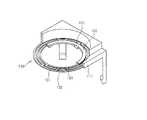
図1aおよび図1bのように、U型断面を有するヨーク12の内側には一対のマグネット13が固定され、上記マグネット13とヨーク12の内周面の間にはその外側にコイル23が巻線されたバレルホルダー22が配置されることにより上記マグネット13とコイル23は隣接するよう配置される。 As shown in FIGS. 1 a and 1 b, a pair of
この際、上記バレルホルダー22はその中央部に形成された開口にスクリューなどによって結合されるレンズバレル21を具備する。上記レンズバレル21は少なくとも一つのレンズ25が内蔵されているので上記バレルホルダー22が動きによって焦点距離が変化するようになる。 At this time, the
一方、上記ヨーク12は下部ケース11に装着され、上記ヨーク12の上部には上部ケース14が設けられる。On the other hand, the
この際、上記上部ケース14とバレルホルダー22はその上部が板スプリング31によって連結されて上記上部ケース14に対してバレルホルダー23が板スプリング31によって支持される構造を有する。 At this time, the
また、下部ケース11にも別途の板スプリングが装着され得るが、この場合に上記別途の板スプリングは下部ケース11とバレルホルダー22の下側を連結するようになる。 In addition, a separate plate spring can be attached to the
このような構成を有する従来のレンズ移送装置の作用は次のとおりである。 The operation of the conventional lens transfer device having such a configuration is as follows.
コイル23に電流を印加させると、上記コイル23とマグネット13の間には電磁気力が発生されるが、このような電磁気力によって上記バレルホルダー22が直線運動をするようになる。 When a current is applied to the
この際、上記バレルホルダー22に形成されたガイド溝22aがヨーク12の内側に形成されたガイド部12aに案内されるので、上記バレルホルダー22及びレンズバレル21内に固定されたレンズ25が光軸方向に移送される。 At this time, since the
このように、バレルホルダー22が直線運動をするようになると、レンズバレル21内のレンズ25が移動して被写体から反射された光をイメージセンサ50に正確に集光されるようにすることで焦点調節機能が具現される As described above, when the
しかし、上記のように構成された従来の焦点調節装置は次のような問題点があった。 However, the conventional focus adjusting apparatus configured as described above has the following problems.
上記板スプリング31はレンズバレル21の外周面21b、あるいはバレルホルダー22の外周面22aに嵌め込むことによって組み立てられた後ボンディングによって固定されるので、嵌め込み工程で上記板スプリング31が破損される問題点があった。 Since the
また、上記板スプリング31が上部ケース14及びレンズバレル21にボンディングによって接着されるので組み立て作業に困難が多かった。Also, difficulties were often the assembling work since the
とりわけ、板スプリング31の位置設定及び初期弾性力の設定などが不正確であるので、レンズバレル21の初期位置が光軸から外れる恐れがあるだけでなく、上記レンズバレル21が移送される際、光軸方向の移送が正確に具現されないという問題点があった。 In particular, since the position setting of the
本発明は上記のような従来の問題点を解消するためのものであり、バレルホルダーと板スプリングが組み立てが容易であり、板スプリングとケースの組み立て作業を要しない組み立て性の向上されたレンズ移送装置を提供することを目的とする。 The present invention is to solve the above-mentioned conventional problems, and it is easy to assemble the barrel holder and the plate spring, and the lens transfer with improved assemblability that does not require the assembly work of the plate spring and the case. An object is to provide an apparatus.
また、組み立て過程において生じ得る板スプリングの破損防止によって収率が向上され、板スプリングとバレルホルダーとの間の簡単な組み立てを通しても光軸方向の公差管理が容易な組み立て性の向上されたレンズ移送装置を提供することを目的とする。Moreover, the improved yield by preventing breakage of theresulting Ru leaf springcaused in the assembly process, even tolerance management in the optical axis direction through simple assembly easy assembly of the enhanced lens between the plate spring and the barrel holder An object is to provide a transfer device.
また、本発明は二つの板スプリングを利用してガイド部を要しない組み立て性の向上されたレンズ移送装置を提供することを目的とする。 It is another object of the present invention to provide a lens transfer device that uses two plate springs and does not require a guide portion and has improved assemblability.
上記のような目的を成し遂げるための一側面として本発明は、内部に少なくとも一つのレンズが内蔵されたレンズバレルが装着され上記レンズの光軸方向に直線移送される中空型のバレルホルダーと、上記バレルホルダーの外周縁の上部に形成された溝にスナップ結合される突出部が形成された第1ホルダーコネクタ、上記第1ホルダーコネクタの外側にその内側が連結される第1板スプリング、及び上記第1板スプリングの外側に連結される第1本体を具備する上部ケースと、上記バレルホルダーの外周縁の下部に形成された溝にスナップ結合される突出部が形成された第2ホルダーコネクタ、上記第2ホルダーコネクタの外側にその内側が連結される第2板スプリング、及び上記第2板スプリングの外側に連結される第2本体を具備する下部ケースと、上記下部ケースに装着されてその内部にマグネットを具備するヨークと、上記マグネットと一定間隔離隔されて設置され、上記バレルホルダーとともに移送されるコイルとを含むレンズ移送装置を提供する。 As one aspect for achieving the above object, the present invention includes a hollow barrel holder in which a lens barrel in which at least one lens is built is mounted and linearly moved in the optical axis direction of the lens, A first holder connector having a protrusion formed in a groove formed at an upper portion of an outer peripheral edge of the barrel holder; a first plate spring having an inner side connected to an outer side of the first holder connector; An upper case having a first body connected to the outer side of the one-plate spring; a second holder connector having a protruding portion that is snap-coupled to a groove formed at a lower portion of the outer peripheral edge of the barrel holder; A second plate spring connected to the outside of the two-holder connector and a second body connected to the outside of the second plate spring; And Department case, a yoke having a magnet therein is mounted on the lower case, are installed for a certain distance apart from the above magnet, to provide a lens driving device including a coil which is transported together with the barrel holder.
好ましくは、上記第1板スプリングは上記第1本体内にインサートモールディングされ、上記第2板スプリングは上記第2本体内にインサートモールディングされる。Preferably, the first plate spring is insertedM o Rudingu in the first body, the second plate spring is insertedM o Rudingu in the second body.
さらに好ましくは、上記第1板スプリングは上記第1本体と第1ホルダーコネクタ内にインサートモールディングされ、上記第2板スプリングは上記第2本体と第2ホルダーコネクタ内にインサートモールディングされ得る。More preferably, the first plate spring is insertedM o Rudingu to the first body and the first holder in the connector, the second plate spring can be insertedM o Rudingu to the second body and the second holder in the connector .
また、上記コイルは上記第1ホルダーコネクタの下面に接着されて設置され、上記ヨークに設置されたマグネットと一定間隔離隔されて配置されるのが好ましい。Moreover, the coil is placed is bonded to the lower surface of the first holder connector, the magnet installed in the yoke Ruis spaced apart from a predetermined distance is preferred.
そして、上記第1板スプリングと第2板スプリングは上記バレルホルダーに同一な弾性力を提供するように形成されて上記バレルホルダーの光軸方向移送を案内するのが好ましい。 The first plate spring and the second plate spring are preferably formed to provide the same elastic force to the barrel holder to guide the barrel holder in the optical axis direction.
他の側面として本発明は、内部に少なくとも一つのレンズが内蔵されたレンズバレルが装着され、外周面にコイルが巻線され上記レンズの光軸方向に直線移送される中空型のバレルホルダーと、上記バレルホルダーの外周縁の上部に形成された溝にスナップ結合される突出部が形成されたホルダーコネクタ、上記ホルダーコネクタの外側にその内側が連結される板スプリング、及び上記板スプリングの外側に連結される本体を具備する上部ケースと、上記バレルホルダーに形成されたガイド溝に挿入されるガイド部、及び上記ガイド部と外周面の間にマグネットを具備するヨークと、上記ヨークが装着される下部ケースとを含むレンズ移送装置を提供する。As another aspect, the present invention provides a hollow barrel holder in which a lens barrel having at least one lens incorporated therein is mounted, a coil is wound on the outer peripheral surface, and linearly transferred in the optical axis direction of the lens, A holder connector having a protrusion formed to be snap-coupled to a groove formed at an upper portion of the outer peripheral edge of the barrel holder, a plate spring connected to the outside of the holder connector, and connected to the outside of the plate spring a yoke comprising an upper case, the guide portion to be inserted into the guide groove formed in the barrel holder, and a magnet between the guide portion and the outer peripheral surface having a body that is, the yoke isinstrumentation wear A lens transfer device including a lower case is provided.
好ましくは、上記板スプリングは上記本体内にインサートモールディングされることもでき、上記本体及び上記ホルダーコネクタ内にインサートモールディングされることもできる。Preferably, the plate spring can also be insertedM o Rudingu in the body, it may also be insertedM o Rudingu in the body and in the holder connector.
さらに他の側面として本発明は、内部に少なくとも一つのレンズが内蔵されたレンズバレルが装着され上記レンズの光軸方向に直線移送される中空型のバレルホルダーと、上記バレルホルダーの外周縁に形成された溝にスナップ結合される突出部が形成されたホルダーコネクタ、上記ホルダーコネクタの外側にその内側が連結される板スプリング、及び上記板スプリングの外側に連結される本体を具備するケースと、上記ケースに装着され、その内部にマグネットを具備するヨーク、及び上記マグネットと一定間隔離隔されて設置され上記バレルホルダーとともに移送されるコイルを含むレンズ移送装置を提供する。 According to another aspect of the present invention, there is provided a hollow barrel holder in which a lens barrel having at least one lens incorporated therein is mounted and linearly transferred in the optical axis direction of the lens, and formed on an outer peripheral edge of the barrel holder. A holder connector formed with a projecting portion that is snap-coupled to the groove, a plate spring that is connected to the outside of the holder connector, and a body that is connected to the outside of the plate spring; and Provided is a lens transfer device including a yoke mounted on a case and having a magnet therein, and a coil that is installed at a certain distance from the magnet and is transferred together with the barrel holder.
好ましくは、上記板スプリングは上記本体内にインサートモールディングされることもでき、上記本体及び上記ホルダーコネクタ内にインサートモールディングされることも可能である。Preferably, the plate spring can also be insertedM o Rudingu in the body, it is also possible to insertM o Rudingu in the body and in the holder connector.
さらに、上記コイルは上記ホルダーコネクタに接着されて設置され、上記ヨークに設置されたマグネットと一定間隔離隔されて配置されるのが好ましい。Furthermore, the coil is placed is bonded to the holder connector, the a the installed magnet the yoke Ruis spaced apart from a predetermined distance is preferred.
本発明によれば、板スプリングがケースと一体で形成されるのでケースに板スプリングを組み立てる必要がなく、板スプリングに突出部を有するホルダーコネクタと上記突出部を収容する溝が形成されたバレルホルダーを具備することで板スプリングとバレルホルダーとの間の組み立てがスナップ結合によって非常に簡単になるので、組み立て性が向上するという効果を得ることができる。 According to the present invention, since the plate spring is formed integrally with the case, there is no need to assemble the plate spring in the case, and the barrel connector is formed with a holder connector having a protruding portion on the plate spring and a groove for accommodating the protruding portion. Since the assembly between the plate spring and the barrel holder becomes very simple by snap coupling, the effect of improving the assemblability can be obtained.
また、本発明は従来の嵌め込み後、ボンディング方式ではなく板スプリングとバレルホルダーとの間のスナップ結合によって行われるので組み立て過程で生じ得る板スプリングの破損を防止することができ、これによって収率が向上されるという有利な効果を得ることができる。Further, the present invention can prevent conventional post fitted, damage to theresulting Ru leaf springcaused by the assembly process because performed by a snap coupling between the plate spring and the barrel holder rather than the bonding method, whereby the yield The advantageous effect of improving can be obtained.
そして、板スプリングがインサートモールディングによってケースに直接形成されるので、単純なスナップ結合だけでも光軸方向の公差管理が容易であり、ボンディング作業が不要であるためボンディングによる弾性力の差が発生する恐れがないという効果を得ることができる。And, since the plate spring is formed directly on the casing by insertM o Rudingu, a simple snap connection alone easy tolerance control of the optical axis direction, the difference between the elastic force of the bonding because the bonding work is required occurs The effect that there is no fear of doing can be acquired.
さらに、二つの板スプリングを上部及び下部ケースに設定する場合にガイド部が不要であるという効果を得ることができる。 Further, when the two plate springs are set in the upper case and the lower case, an effect that a guide portion is unnecessary can be obtained.
以下、添付の図面に基づいて本発明を詳しく説明する。 Hereinafter, the present invention will be described in detail with reference to the accompanying drawings.
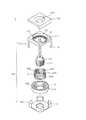
図2aは、本発明の第1実施例によるレンズ移送装置の主要部品の分解斜視図で、図2bは図2aに示すレンズ移送装置の結合断面図であり、図3a及び図3bは、それぞれ図2a及び図2bの上部ケース、下部ケース及びバレルホルダーの分解斜視図と結合された状態の断面図であり、図4は図2a及び図2bの上部ケースの部分切開斜視図である。 2a is an exploded perspective view of the main components of the lens transfer device according to the first embodiment of the present invention, FIG. 2b is a sectional view of the lens transfer device shown in FIG. 2a, and FIGS. 3a and 3b are respectively diagrams. FIG. 4 is a cross-sectional view of the upper case, the lower case, and the barrel holder of FIGS. 2a and 2b combined with an exploded perspective view, and FIG. 4 is a partially cutaway perspective view of the upper case of FIGS. 2a and 2b.
本発明は板スプリングをインサートモールディングを通してケースと一体で成形し、上記板スプリングに連結されたホルダーコネクタとバレルホルダーがスナップ結合を通して組み立てられ、従来に比して組み立て性の向上されたレンズ移送装置に関するものである。The present invention is molded in the case and integrally leaf spring through insertM o Rudingu, the plate linked holder connector and the barrel holder spring are assembled through snap-lens transfer that is improve the assembling efficiency in comparison with the conventional It relates to the device.
図2a及び図2bに示すように、本発明の第1実施例による組み立て性の容易なレンズ移送装置1はバレルホルダー220、第1板スプリング130と連結された上部ケース110、 第2板スプリング140と連結された下部ケース120、マグネット180を具備するヨーク170及びコイル230を含んで構成される。 As shown in FIGS. 2a and 2b, the
図2に示すように、上記バレルホルダー220の内部には少なくとも一つのレンズ(L)が内蔵されたレンズバレル210が装着される。この際、上記レンズ(L)は具現しようとするカメラの機能及び性能によって一つまたは多数個が設置されることができ、この中の一部のレンズはバレルホルダー220の移送にもかかわらず固定された位置を維持するように形成することもできる。また、上記レンズバレル210の外周面に形成されたねじ山211は上記バレルホルダー220の内周面に形成されたねじ山223に沿ってねじ結合される。一方、上記バレルホルダー220の外周面には後述するところのようにホルダーコネクタ (151、161)がスナップ結合されるための溝(221、222)が形成される。 As shown in FIG. 2, a
また、図2のようにヨーク170内部には磁気力を発生させるマグネット180が装着され、上記ヨーク170は磁束をインタラプトするためにU型断面を有するのが好ましい。Also, as shown in FIG. 2, a
この際、上記マグネット180とヨーク170の内側壁面171の間には上記マグネット180と一定間隔離隔されるようにコイル230が具備される。上記コイル230は図面で図示されてなかったが、電源(power source)と電気的に連結され電源から電流が供給されるよう構成され、これによってコイル230とマグネット180との間の電磁気力相互作用によってコイル230が移送される。At this time, a
一方、本発明によるレンズ移送装置1は上部ケース110と下部ケース120からなるケース100を具備する。上記ケース100は上記ヨーク170及びバレルホルダー220などの部品を実装できるように所定の内部空間が形成されており、外部から内部に実装された部品を保護する役割をする。 Meanwhile, the
この際、上記上部ケース110は上記バレルホルダー220の外周縁の上部に形成された溝221にスナップ結合される突出部151が形成された第1ホルダーコネクタ150と、上記第1ホルダーコネクタ150の外側にその内側が連結される第1板スプリング130と、上記第1板スプリング130の外側に連結される第1本体111を具備する。 At this time, the
同様に上記下部ケース120は、上記バレルホルダー220の外周縁の下部に形成された溝222にスナップ結合される突出部161が形成された第2ホルダーコネクタ160と、上記第2ホルダーコネクタ160の外側にその内側が連結される第2板スプリング140と、上記第2板スプリング140の外側に連結される第2本体121を具備し、その下部面に上記ヨーク170が装着される。Similarly, the
このように連結される本体(111、121)、板スプリング(130、140)、ホルダーコネクタ(150、160)はインサートモールディングによって形成されるのが好ましい。Body (111, 121) connected in this way, the plate spring (130, 140), the holder connector (150, 160) is preferably formed by insertM o Rudingu.
この際、上記板スプリング(130、140)は十分な剛性を有し、弾性力を提供することができるように金属製より形成され得、本体(111、121)とホルダーコネクタ(150、160)はプラスチック製より形成され得る。 At this time, the leaf springs (130, 140) have sufficient rigidity and may be formed of metal so as to provide elasticity, and the main body (111, 121) and the holder connector (150, 160). Can be made of plastic.
図3a及び図3bにはこのような上部ケース110、下部ケース120及びバレルホルダー220の結合関係が詳細に図示されている。 FIGS. 3A and 3B illustrate the connection relationship between the
すなわち、上部ケース110の第1ホルダーコネクタ150の突出部151はバレルホルダー220の外周面上部に形成された溝221にスナップ結合され、下部ケース120の第2ホルダーコネクタ160の突出部161はバレルホルダー220の外周面下部に形成された溝222にスナップ結合される。 That is, the
従来の場合には板スプリングとバレルホルダーが嵌め込み方式で結合された後、ボンディングによって固定されるので板スプリングの破損による収率低下が大きな問題として台頭され、組み立て作業が不便で、光軸方向の公差管理が難しかったが、本発明のようにスナップ結合によって板スプリングとバレルホルダーが連結される場合には前述した従来の問題点が解決できるという利点がある。 In the conventional case, the plate spring and the barrel holder are joined together by fitting, and then fixed by bonding. Therefore, a decrease in yield due to the breakage of the plate spring has emerged as a major problem, making assembly work inconvenient and in the optical axis direction. Although the tolerance management is difficult, there is an advantage that the conventional problems described above can be solved when the leaf spring and the barrel holder are connected by snap coupling as in the present invention.
好ましくは、図2b及び3bに示すように、上記コイル230は上記第1 ホルダーコネクタ150の下面にボンディングなどによって接着されて上記ヨーク170に設置されたマグネット180と一定間隔離隔されるように配置することができる。このようにコイル230が実装される場合には従来とは違ってコイル230がバレルホルダー220に直接巻線されなくても良いのでバレルホルダー220の製作が容易で、かつ設計自由度が向上されるという利点がある。Preferably, as shown in Fig. 2b and 3b,placed so that the
一方、図4には上部ケース110を部分切開した斜視図が図示されている。
図4に示すように、上記板スプリング130は外側部131、中間部132、内側部133に区分することができ、外側部131は本体111に、内側部133はホルダーコネクタ150にインサートモールディングされ、中間部132は弾性的に変形されバレルホルダー220の移送に必要な変位を提供するようになる。この際、ホルダーコネクタ150の内側には突出部151が形成されてバレルホルダー220に形成された溝221とスナップ結合される。Meanwhile, FIG. 4 is a perspective view in which the
As shown in FIG. 4, the
これとは違って、外側部131のみが本体111にインサートモールディングされ、内側部133にはホルダーコネクタ150がボンディングなどによって接合されるように構成することもあり得る。Unlike this, only the
このような図4の板スプリング130の形状は一例として提示されたものに過ぎず、このようにインサートモールディングされることができる構造なら、図4の形状に限定されない。Shape of the
また、下部ケース120に具備される板スプリング140も上記のようにインサートモールディングによって解形成され得る。The
好ましくは、図2b及び図3bに示すように上記第1板スプリング130と第2板スプリング140は上記バレルホルダー220に同一な弾性力を提供するように形成されるのが好ましい。 2B and 3B, the
すなわち、上記バレルホルダー220の上下に同一な弾性力が作用するようになると、バレルホルダー220の光軸方向移送を案内する案内部が具備されなくても上記第1及び第2板スプリング(130、140)の相互作用によって光軸方向の移送を具現できるようになる。 That is, when the same elastic force is applied to the top and bottom of the
このために上記第1及び第2板スプリング(130、140)は同一な形状と材質を有するのが好ましいが、バレルホルダー220の光軸方向移送を案内することが可能な弾性力が提供できれば、これに限定されない。 For this purpose, the first and
図5aと図5bは、それぞれ本発明の第2実施例によるレンズ移送装置の主要部品の分解斜視図と結合断面図である。 5a and 5b are an exploded perspective view and a combined sectional view of main components of a lens transfer device according to a second embodiment of the present invention, respectively.
図5a及び図5bに示すように、本発明の第2実施例による組み立て性の容易なレンズ移送装置1は外周面にコイル230が巻線されたバレルホルダー220、第1板スプリング130と連結された上部ケース110、マグネット180を具備するヨーク170及び上記ヨーク170が装着される下部ケース120を含んで構成される。As shown in FIGS. 5a and 5b, the easy-to-assemble
本発明の第2実施例によるレンズ移送装置はコイル230がバレルホルダー220の外周面に巻線され、上記バレルホルダー220にガイド溝225が形成されること、下部ケース120に板スプリング及びホルダーコネクタが具備されないことを除けば基本的に第1実施例と同じであり、重複された記載を避けるために詳しい説明は省略する。 In the lens transfer device according to the second embodiment of the present invention, a
以下、第1実施例と相異な点を中心に説明する。 The following description will focus on the differences from the first embodiment.
図5a及び図5bに示すように、本発明の第2実施例によるレンズ移送装置1はバレルホルダー220の外周面上側でのみスナップ結合のための溝221が形成され、この溝221に上部ケース110の板スプリング130と連結されたホルダーコネクタ150の突出部151がスナップ結合される。 As shown in FIGS. 5 a and 5 b, the
また、バレルホルダー220の外周面にはコイル230が巻線され、上記コイル230がヨーク170内のマグネット180と一定間隔離隔され配置されるようにバレルホルダー220にはガイド溝225が形成されている。A
すなわち、上記ガイド溝225はヨーク170のガイド部172に挿入されて光軸方向へバレルホルダー220の移送を案内する役目及び上記コイル230がマグネット180と一定間隔を維持しヨーク170内に位置するようにする役目を果たす。 That is, the
図5a及び図5bに示す第2実施例によるレンズ移送装置1は上部ケース110でのみ板スプリング130がインサートモールディングされ形成されるのであり、バレルホルダー220の光軸方向移送は上記ガイド部172及びガイド溝225によって行われる。5a and
一方、本発明によるレンズ移送装置1はU型断面を有するヨーク170を中心に図示説明したが、上記ヨーク170はL型断面を有することもでき、さらに音声コイルモーターを利用したレンズ移送装置で公知されたように逆U型断面を有するヨークに対しても適用可能である。 On the other hand, the
このように、逆U型断面を有する場合には本発明の実施例で示すコイル230がヨーク170内に下側から上側へ挿入されるように構成すれば良いが、この場合に第2実施例は下部ケース120に板スプリングが具備される構成になり得る。 Thus, in the case of having an inverted U-shaped cross section, the
また、光軸方向の移送が保障されれば、別途のガイド部が具備されなくても上部ケース110または下部ケース120の一側でのみ板スプリング及び突出部が具備されたホルダーコネクタが連結されるように構成することもあり得る。 Further, if the transfer in the optical axis direction is guaranteed, the holder connector having the plate spring and the protruding portion is connected only on one side of the
上記のような構成を有する本発明の作用は次のとおりである。 The operation of the present invention having the above-described configuration is as follows.
図2bに示すようにコイル230に電流が印加されると、フレミングの左手法則によって発生されるコイル230とマグネット180の電磁気力によってコイル230が直線的に移送される。 As shown in FIG. 2 b, when a current is applied to the
第1実施例の場合にはコイル230が接着されたホルダーコネクタ150に移送力が加えられ、これによってホルダーコネクタ150に連結された板スプリング130が弾性的に変形するようになりバレルホルダー220の移送に必要な変位を提供するようになる。 In the case of the first embodiment, a transfer force is applied to the
すなわち、コイル230に印加される電流によってバレルホルダー220が図2bのY方向へ直線移送され、これによってバレルホルダー220内にレンズバレル210を介して装着されたレンズ(L)が移送するようになり、これによってイメージセンサ(図示せず)とレンズ(L)との間の相手距離の変化で焦点調節またはズーム機能が行われる。 That is, the
この際、第1板スプリング130と第2板スプリング140に作用する弾性力のバランスによって別途のガイド部がなくても光軸方向の移送が行われるようになるという利点がある。 At this time, there is an advantage that the transfer in the optical axis direction can be performed without a separate guide due to the balance of elastic forces acting on the
一方、第2実施例の場合には図5bに示すように、コイル230に電流が印加されると、コイル230が巻線されたバレルホルダー220が移送され、この際バレルホルダー220のガイド溝225に挿入されるガイド部172によって光軸方向(Y)の移送が起こるようになる。On the other hand, in the case of the second embodiment, as shown in FIG. 5 b, when a current is applied to the
上記で本発明は、特定の実施例について図示、説明したが、当業界において通常の知識を有する者であれば添付の特許請求範囲に記載された本発明の思想及び領域を外れない範囲内において本発明を多様に修正及び変更させられることが判る。しかし、このような修正及び変更構造らは全て本発明の権利範囲内に含まれることを明らかにしておく。 While the present invention has been illustrated and described with reference to specific embodiments, those skilled in the art will recognize that the invention is within the spirit and scope of the invention as set forth in the appended claims. It can be seen that the present invention can be modified and changed in various ways. However, it will be clear that all such modifications and changes are within the scope of the present invention.
100 ケース 110 上部ケース
111 第1本体 120 下部ケース
121 第2本体 130 第1板スプリング
140 第2板スプリング 150 第1ホルダーコネクタ
160 第2ホルダーコネクタ 170 ヨーク
172 ガイド部 180 マグネット
210 レンズバレル 220 バレルホルダー
221 上部溝 222 下部溝
225 ガイド溝 230 コイル
400 シャッター
DESCRIPTION OF
Claims (12)
Translated fromJapanese上記バレルホルダーの外周縁の上部に形成された溝にスナップ結合される突出部が形成された第1ホルダーコネクタ、上記第1ホルダーコネクタの外側にその内側が連結される第1板スプリング、及び上記第1板スプリングの外側に連結される第1本体を具備する上部ケースと、
上記バレルホルダーの外周縁の下部に形成された溝にスナップ結合される突出部が形成された第2ホルダーコネクタ、上記第2ホルダーコネクタの外側にその内側が連結される第2板スプリング、及び上記第2板スプリングの外側に連結される第2本体を具備する下部ケースと、
上記下部ケースに装着されその内部にマグネットを具備するヨークと、
上記マグネットと一定間隔離隔され設置されて上記バレルホルダーとともに移送されるコイルと
を含むレンズ移送装置。A hollow barrel holder that is mounted with a lens barrel containing at least one lens therein and is linearly transferred in the optical axis direction of the lens;
A first holder connector formed with a protrusion that is snap-coupled to a groove formed at an upper portion of an outer peripheral edge of the barrel holder; a first plate spring having an inner side connected to an outer side of the first holder connector; and An upper case having a first body coupled to the outside of the first leaf spring;
A second holder connector formed with a protrusion that is snap-coupled to a groove formed at a lower portion of the outer peripheral edge of the barrel holder; a second plate spring that is connected to the outside of the second holder connector; A lower case having a second body coupled to the outside of the second plate spring;
A yoke mounted on the lower case and having a magnet therein;
A lens transfer device comprising: the magnet and a coil that is spaced apart by a certain distance and transferred together with the barrel holder.
上記第2板スプリングは上記第2本体内にインサートモールディングされることを特徴とする請求項1に記載のレンズ移送装置。The first plate spring is insertedM o Rudingu in the first body,
Said second plate spring is lens driving device as set forth in claim 1, characterized in that the insertM o Rudingu in the second body.
上記第2板スプリングは上記第2本体と第2ホルダーコネクタ内にインサートモールディングされることを特徴とする請求項1に記載のレンズ移送装置。The first plate spring is insertedM o Rudingu to the first body and the first holder in the connector,
Said second plate spring is lens driving device as set forth in claim 1, characterized in that the insertM o Rudingu to the second body and the second holder in the connector.
上記バレルホルダーの外周縁の上部に形成された溝にスナップ結合される突出部が形成されたホルダーコネクタ、上記ホルダーコネクタの外側にその内側が連結される板スプリング、及び上記板スプリングの外側に連結される本体を具備する上部ケースと、
上記バレルホルダーに形成されたガイド溝に挿入されるガイド部と、上記ガイド部と外周面との間にマグネットを具備するヨークと、
上記ヨークが装着される下部ケースと
を含むレンズ移送装置。A hollow barrel holder in which a lens barrel containing at least one lens is mounted, a coil is wound on the outer peripheral surface, and is linearly transferred in the optical axis direction of the lens,
A holder connector formed with a protrusion that is snap-coupled to a groove formed at an upper portion of the outer peripheral edge of the barrel holder, a plate spring connected to the outside of the holder connector, and connected to the outside of the plate spring An upper case having a body to be made;
A guide portion inserted into a guide groove formed in the barrel holder, and a yoke having a magnet between the guide portion and the outer peripheral surface;
Lens driving device including a lower case in which the yoke isinstrumentation wear.
上記バレルホルダーの外周縁に形成された溝にスナップ結合される突出部が形成されたホルダーコネクタ、上記ホルダーコネクタの外側にその内側が連結される板スプリング、及び上記板スプリングの外側に連結される本体を具備するケースと、
上記ケースに装着され、その内部にマグネットを具備するヨークと、
上記マグネットと一定間隔離隔されて設置され上記バレルホルダーとともに移送されるコイルと
を含むレンズ移送装置。A hollow barrel holder that is mounted with a lens barrel containing at least one lens therein and is linearly transferred in the optical axis direction of the lens;
A holder connector formed with a protrusion that is snap-coupled to a groove formed on the outer peripheral edge of the barrel holder, a plate spring that is connected to the outside of the holder connector, and a plate spring that is connected to the outside of the plate spring A case having a main body;
A yoke mounted on the case and having a magnet therein;
A lens transfer device comprising: a coil that is installed at a certain distance from the magnet and is transferred together with the barrel holder.
Applications Claiming Priority (1)
| Application Number | Priority Date | Filing Date | Title |
|---|---|---|---|
| KR1020050031950AKR100649638B1 (en) | 2005-04-18 | 2005-04-18 | Lens transport device with improved assembly |
Publications (2)
| Publication Number | Publication Date |
|---|---|
| JP2006301584A JP2006301584A (en) | 2006-11-02 |
| JP4509942B2true JP4509942B2 (en) | 2010-07-21 |
Family
ID=37234180
Family Applications (1)
| Application Number | Title | Priority Date | Filing Date |
|---|---|---|---|
| JP2006006754AExpired - Fee RelatedJP4509942B2 (en) | 2005-04-18 | 2006-01-13 | Lens transfer device with improved assembly |
Country Status (3)
| Country | Link |
|---|---|
| US (1) | US20060245085A1 (en) |
| JP (1) | JP4509942B2 (en) |
| KR (1) | KR100649638B1 (en) |
Families Citing this family (25)
| Publication number | Priority date | Publication date | Assignee | Title |
|---|---|---|---|---|
| US7813634B2 (en) | 2005-02-28 | 2010-10-12 | Tessera MEMS Technologies, Inc. | Autofocus camera |
| US7345827B1 (en)* | 2005-02-28 | 2008-03-18 | Siimpel Corporation | Lens barrel |
| TWM310356U (en)* | 2006-08-23 | 2007-04-21 | Lite On Technology Corp | Optical device |
| JP2008058734A (en)* | 2006-08-31 | 2008-03-13 | Mitsumi Electric Co Ltd | Camera module |
| KR20080024030A (en)* | 2006-09-12 | 2008-03-17 | 엘지이노텍 주식회사 | Flash device of mobile terminal |
| KR100817033B1 (en)* | 2006-10-24 | 2008-03-27 | 재영솔루텍 주식회사 | Auto focusing device of small lens module |
| KR101210165B1 (en)* | 2006-12-13 | 2012-12-07 | 엘지이노텍 주식회사 | Motor for driving lens |
| EP3699663B1 (en)* | 2006-12-13 | 2024-04-03 | Lg Innotek Co. Ltd | Lens driving apparatus |
| KR101209956B1 (en)* | 2006-12-13 | 2012-12-07 | 엘지이노텍 주식회사 | Motor for driving lens |
| JP4992444B2 (en)* | 2007-02-02 | 2012-08-08 | ミツミ電機株式会社 | The camera module |
| GB0702897D0 (en)* | 2007-02-15 | 2007-03-28 | Johnson Electric Sa | Voice coil motor |
| KR101141722B1 (en)* | 2007-05-30 | 2012-05-04 | 삼성테크윈 주식회사 | Voice coil module |
| CN101452107A (en)* | 2007-12-06 | 2009-06-10 | 鸿富锦精密工业(深圳)有限公司 | Lens module and camera module |
| EP2101214A1 (en)* | 2008-03-13 | 2009-09-16 | Tdk Taiwan Corp. | EMI-proof miniature lens focusing mechanism |
| JP2009300552A (en)* | 2008-06-11 | 2009-12-24 | Kantatsu Co Ltd | Imaging lens unit |
| CN101645640B (en)* | 2008-08-05 | 2012-03-28 | 鸿富锦精密工业(深圳)有限公司 | voice coil motor |
| JP2010085494A (en)* | 2008-09-29 | 2010-04-15 | Sony Corp | Lens driver, camera module, imaging apparatus, and camera-equipped mobile terminal |
| JP5181208B2 (en)* | 2008-12-01 | 2013-04-10 | セイコーインスツル株式会社 | Drive module and electronic device |
| JP2010151007A (en)* | 2008-12-25 | 2010-07-08 | Seiko Instruments Inc | Driving module and electronic device |
| JP5295830B2 (en)* | 2009-03-17 | 2013-09-18 | アルプス電気株式会社 | Lens drive device |
| KR101621895B1 (en)* | 2009-12-28 | 2016-05-17 | 엘지이노텍 주식회사 | Stabilized camera module |
| JP2015092213A (en)* | 2013-11-08 | 2015-05-14 | 惠州市大亜湾永昶電子工業有限公司 | Lens driving device |
| JP2019095662A (en)* | 2017-11-24 | 2019-06-20 | 株式会社ブイ・テクノロジー | Attachment structure of optical device and exposure device |
| CN108322633A (en)* | 2018-03-05 | 2018-07-24 | 信利光电股份有限公司 | A kind of imaging modules and electronic device |
| CN108710189B (en)* | 2018-07-04 | 2024-08-16 | 上海比路电子股份有限公司 | Lens driving motor, camera and mobile terminal device |
Family Cites Families (12)
| Publication number | Priority date | Publication date | Assignee | Title |
|---|---|---|---|---|
| JP3163789B2 (en)* | 1992-09-18 | 2001-05-08 | ソニー株式会社 | Camera lens barrel |
| JP3434097B2 (en)* | 1995-09-29 | 2003-08-04 | オリンパス光学工業株式会社 | Fine movement mechanism |
| US6195212B1 (en)* | 1998-11-11 | 2001-02-27 | Nikon Corporation | Variable focal length lens barrel |
| JP2000275490A (en)* | 1999-03-23 | 2000-10-06 | Sony Corp | Optical axis correcting device and its manufacture |
| JP2002048978A (en)* | 2000-08-01 | 2002-02-15 | Olympus Optical Co Ltd | Objective lens unit, optical device having objective lens unit and observation method using the optical device |
| JP2003115127A (en)* | 2001-10-01 | 2003-04-18 | Sony Corp | Optical pickup device |
| JP2003295033A (en)* | 2002-04-02 | 2003-10-15 | Shicoh Eng Co Ltd | Lens driving device |
| JP4250409B2 (en)* | 2002-12-04 | 2009-04-08 | 日本電産サンキョー株式会社 | Lens drive device |
| JP2004354497A (en)* | 2003-05-27 | 2004-12-16 | Mitsumi Electric Co Ltd | Mounting mechanism of lens barrel |
| KR100548869B1 (en) | 2004-12-10 | 2006-02-08 | 주식회사 하이소닉 | Small camera |
| KR100562723B1 (en)* | 2004-05-01 | 2006-03-20 | 주식회사 포엠 | Compact camera device for communication device and communication device having same |
| KR100562720B1 (en)* | 2004-05-19 | 2006-03-20 | 주식회사 포엠 | Compact camera device for communication device and communication device having same |
- 2005
- 2005-04-18KRKR1020050031950Apatent/KR100649638B1/ennot_activeExpired - Fee Related
- 2006
- 2006-01-13JPJP2006006754Apatent/JP4509942B2/ennot_activeExpired - Fee Related
- 2006-01-13USUS11/331,167patent/US20060245085A1/ennot_activeAbandoned
Also Published As
| Publication number | Publication date |
|---|---|
| KR100649638B1 (en) | 2006-11-27 |
| US20060245085A1 (en) | 2006-11-02 |
| JP2006301584A (en) | 2006-11-02 |
| KR20060109690A (en) | 2006-10-23 |
Similar Documents
| Publication | Publication Date | Title |
|---|---|---|
| JP4509942B2 (en) | Lens transfer device with improved assembly | |
| JP6138969B2 (en) | The camera module | |
| CN114785915B (en) | Voice Coil Motor and Camera Module | |
| JP6250597B2 (en) | Electromagnetic drive module and lens device using the same | |
| KR20150007665A (en) | Camera module | |
| JP4792511B2 (en) | The camera module | |
| KR102214331B1 (en) | Camera module | |
| US20210124095A1 (en) | Thin lens optical module, particularly for autofocus | |
| CN105659137A (en) | Lens-driving device | |
| US20200089088A1 (en) | Dual camera module | |
| KR20140107903A (en) | Camera module | |
| KR101079026B1 (en) | Autofocus Optics and Imaging Devices Applied to the Same | |
| KR20100124135A (en) | Lens actuator for image pickup apparatus | |
| KR100985665B1 (en) | Camera module | |
| KR20220074675A (en) | Camera actuator and Folded zoom camera module containing the same | |
| KR100919116B1 (en) | Autofocus lens assembly for mobile devices with improved driving power | |
| KR102405978B1 (en) | Voice coil motor | |
| KR101896991B1 (en) | Camera apparatus with plate spring | |
| KR102375333B1 (en) | Camera module | |
| CN222599935U (en) | Frame of lens driving device | |
| KR102712760B1 (en) | Motor for actuating lens | |
| KR102784597B1 (en) | Motor for actuating lens | |
| KR102438669B1 (en) | lens drive motor | |
| KR102186479B1 (en) | Voice coil motor | |
| KR100247764B1 (en) | Yoke and magnet coupling structure of linear motor for video camera |
Legal Events
| Date | Code | Title | Description |
|---|---|---|---|
| A977 | Report on retrieval | Free format text:JAPANESE INTERMEDIATE CODE: A971007 Effective date:20080626 | |
| A131 | Notification of reasons for refusal | Free format text:JAPANESE INTERMEDIATE CODE: A131 Effective date:20080708 | |
| A521 | Request for written amendment filed | Free format text:JAPANESE INTERMEDIATE CODE: A523 Effective date:20081007 | |
| TRDD | Decision of grant or rejection written | ||
| A01 | Written decision to grant a patent or to grant a registration (utility model) | Free format text:JAPANESE INTERMEDIATE CODE: A01 Effective date:20100406 | |
| A01 | Written decision to grant a patent or to grant a registration (utility model) | Free format text:JAPANESE INTERMEDIATE CODE: A01 | |
| A61 | First payment of annual fees (during grant procedure) | Free format text:JAPANESE INTERMEDIATE CODE: A61 Effective date:20100428 | |
| FPAY | Renewal fee payment (event date is renewal date of database) | Free format text:PAYMENT UNTIL: 20130514 Year of fee payment:3 | |
| R150 | Certificate of patent or registration of utility model | Free format text:JAPANESE INTERMEDIATE CODE: R150 | |
| FPAY | Renewal fee payment (event date is renewal date of database) | Free format text:PAYMENT UNTIL: 20130514 Year of fee payment:3 | |
| FPAY | Renewal fee payment (event date is renewal date of database) | Free format text:PAYMENT UNTIL: 20140514 Year of fee payment:4 | |
| R250 | Receipt of annual fees | Free format text:JAPANESE INTERMEDIATE CODE: R250 | |
| LAPS | Cancellation because of no payment of annual fees |