JP4509578B2 - Laser processing method and laser processing apparatus - Google Patents
Laser processing method and laser processing apparatusDownload PDFInfo
- Publication number
- JP4509578B2 JP4509578B2JP2004004304AJP2004004304AJP4509578B2JP 4509578 B2JP4509578 B2JP 4509578B2JP 2004004304 AJP2004004304 AJP 2004004304AJP 2004004304 AJP2004004304 AJP 2004004304AJP 4509578 B2JP4509578 B2JP 4509578B2
- Authority
- JP
- Japan
- Prior art keywords
- lens
- main surface
- laser
- laser beam
- processing
- Prior art date
- Legal status (The legal status is an assumption and is not a legal conclusion. Google has not performed a legal analysis and makes no representation as to the accuracy of the status listed.)
- Expired - Lifetime
Links
Images


Classifications
- B—PERFORMING OPERATIONS; TRANSPORTING
- B23—MACHINE TOOLS; METAL-WORKING NOT OTHERWISE PROVIDED FOR
- B23K—SOLDERING OR UNSOLDERING; WELDING; CLADDING OR PLATING BY SOLDERING OR WELDING; CUTTING BY APPLYING HEAT LOCALLY, e.g. FLAME CUTTING; WORKING BY LASER BEAM
- B23K26/00—Working by laser beam, e.g. welding, cutting or boring
- B23K26/02—Positioning or observing the workpiece, e.g. with respect to the point of impact; Aligning, aiming or focusing the laser beam
- B23K26/04—Automatically aligning, aiming or focusing the laser beam, e.g. using the back-scattered light
- B23K26/046—Automatically focusing the laser beam
- B23K26/048—Automatically focusing the laser beam by controlling the distance between laser head and workpiece
- B—PERFORMING OPERATIONS; TRANSPORTING
- B23—MACHINE TOOLS; METAL-WORKING NOT OTHERWISE PROVIDED FOR
- B23K—SOLDERING OR UNSOLDERING; WELDING; CLADDING OR PLATING BY SOLDERING OR WELDING; CUTTING BY APPLYING HEAT LOCALLY, e.g. FLAME CUTTING; WORKING BY LASER BEAM
- B23K26/00—Working by laser beam, e.g. welding, cutting or boring
- B23K26/02—Positioning or observing the workpiece, e.g. with respect to the point of impact; Aligning, aiming or focusing the laser beam
- B23K26/04—Automatically aligning, aiming or focusing the laser beam, e.g. using the back-scattered light
- B23K26/046—Automatically focusing the laser beam
- B—PERFORMING OPERATIONS; TRANSPORTING
- B23—MACHINE TOOLS; METAL-WORKING NOT OTHERWISE PROVIDED FOR
- B23K—SOLDERING OR UNSOLDERING; WELDING; CLADDING OR PLATING BY SOLDERING OR WELDING; CUTTING BY APPLYING HEAT LOCALLY, e.g. FLAME CUTTING; WORKING BY LASER BEAM
- B23K26/00—Working by laser beam, e.g. welding, cutting or boring
- B23K26/02—Positioning or observing the workpiece, e.g. with respect to the point of impact; Aligning, aiming or focusing the laser beam
- B23K26/06—Shaping the laser beam, e.g. by masks or multi-focusing
- B23K26/064—Shaping the laser beam, e.g. by masks or multi-focusing by means of optical elements, e.g. lenses, mirrors or prisms
- B23K26/0643—Shaping the laser beam, e.g. by masks or multi-focusing by means of optical elements, e.g. lenses, mirrors or prisms comprising mirrors
- B—PERFORMING OPERATIONS; TRANSPORTING
- B23—MACHINE TOOLS; METAL-WORKING NOT OTHERWISE PROVIDED FOR
- B23K—SOLDERING OR UNSOLDERING; WELDING; CLADDING OR PLATING BY SOLDERING OR WELDING; CUTTING BY APPLYING HEAT LOCALLY, e.g. FLAME CUTTING; WORKING BY LASER BEAM
- B23K26/00—Working by laser beam, e.g. welding, cutting or boring
- B23K26/02—Positioning or observing the workpiece, e.g. with respect to the point of impact; Aligning, aiming or focusing the laser beam
- B23K26/06—Shaping the laser beam, e.g. by masks or multi-focusing
- B23K26/064—Shaping the laser beam, e.g. by masks or multi-focusing by means of optical elements, e.g. lenses, mirrors or prisms
- B23K26/0648—Shaping the laser beam, e.g. by masks or multi-focusing by means of optical elements, e.g. lenses, mirrors or prisms comprising lenses
- B—PERFORMING OPERATIONS; TRANSPORTING
- B23—MACHINE TOOLS; METAL-WORKING NOT OTHERWISE PROVIDED FOR
- B23K—SOLDERING OR UNSOLDERING; WELDING; CLADDING OR PLATING BY SOLDERING OR WELDING; CUTTING BY APPLYING HEAT LOCALLY, e.g. FLAME CUTTING; WORKING BY LASER BEAM
- B23K26/00—Working by laser beam, e.g. welding, cutting or boring
- B23K26/08—Devices involving relative movement between laser beam and workpiece
- B23K26/083—Devices involving movement of the workpiece in at least one axial direction
- B—PERFORMING OPERATIONS; TRANSPORTING
- B23—MACHINE TOOLS; METAL-WORKING NOT OTHERWISE PROVIDED FOR
- B23K—SOLDERING OR UNSOLDERING; WELDING; CLADDING OR PLATING BY SOLDERING OR WELDING; CUTTING BY APPLYING HEAT LOCALLY, e.g. FLAME CUTTING; WORKING BY LASER BEAM
- B23K26/00—Working by laser beam, e.g. welding, cutting or boring
- B23K26/36—Removing material
- B23K26/38—Removing material by boring or cutting
- B—PERFORMING OPERATIONS; TRANSPORTING
- B23—MACHINE TOOLS; METAL-WORKING NOT OTHERWISE PROVIDED FOR
- B23K—SOLDERING OR UNSOLDERING; WELDING; CLADDING OR PLATING BY SOLDERING OR WELDING; CUTTING BY APPLYING HEAT LOCALLY, e.g. FLAME CUTTING; WORKING BY LASER BEAM
- B23K26/00—Working by laser beam, e.g. welding, cutting or boring
- B23K26/36—Removing material
- B23K26/40—Removing material taking account of the properties of the material involved
- B—PERFORMING OPERATIONS; TRANSPORTING
- B23—MACHINE TOOLS; METAL-WORKING NOT OTHERWISE PROVIDED FOR
- B23K—SOLDERING OR UNSOLDERING; WELDING; CLADDING OR PLATING BY SOLDERING OR WELDING; CUTTING BY APPLYING HEAT LOCALLY, e.g. FLAME CUTTING; WORKING BY LASER BEAM
- B23K26/00—Working by laser beam, e.g. welding, cutting or boring
- B23K26/50—Working by transmitting the laser beam through or within the workpiece
- B23K26/53—Working by transmitting the laser beam through or within the workpiece for modifying or reforming the material inside the workpiece, e.g. for producing break initiation cracks
- B—PERFORMING OPERATIONS; TRANSPORTING
- B28—WORKING CEMENT, CLAY, OR STONE
- B28D—WORKING STONE OR STONE-LIKE MATERIALS
- B28D5/00—Fine working of gems, jewels, crystals, e.g. of semiconductor material; apparatus or devices therefor
- B28D5/0005—Fine working of gems, jewels, crystals, e.g. of semiconductor material; apparatus or devices therefor by breaking, e.g. dicing
- B28D5/0011—Fine working of gems, jewels, crystals, e.g. of semiconductor material; apparatus or devices therefor by breaking, e.g. dicing with preliminary treatment, e.g. weakening by scoring
- H—ELECTRICITY
- H01—ELECTRIC ELEMENTS
- H01L—SEMICONDUCTOR DEVICES NOT COVERED BY CLASS H10
- H01L21/00—Processes or apparatus adapted for the manufacture or treatment of semiconductor or solid state devices or of parts thereof
- H01L21/67—Apparatus specially adapted for handling semiconductor or electric solid state devices during manufacture or treatment thereof; Apparatus specially adapted for handling wafers during manufacture or treatment of semiconductor or electric solid state devices or components ; Apparatus not specifically provided for elsewhere
- H01L21/67005—Apparatus not specifically provided for elsewhere
- H01L21/67011—Apparatus for manufacture or treatment
- H01L21/67092—Apparatus for mechanical treatment
- H—ELECTRICITY
- H01—ELECTRIC ELEMENTS
- H01L—SEMICONDUCTOR DEVICES NOT COVERED BY CLASS H10
- H01L21/00—Processes or apparatus adapted for the manufacture or treatment of semiconductor or solid state devices or of parts thereof
- H01L21/70—Manufacture or treatment of devices consisting of a plurality of solid state components formed in or on a common substrate or of parts thereof; Manufacture of integrated circuit devices or of parts thereof
- H01L21/77—Manufacture or treatment of devices consisting of a plurality of solid state components or integrated circuits formed in, or on, a common substrate
- H01L21/78—Manufacture or treatment of devices consisting of a plurality of solid state components or integrated circuits formed in, or on, a common substrate with subsequent division of the substrate into plural individual devices
- B—PERFORMING OPERATIONS; TRANSPORTING
- B23—MACHINE TOOLS; METAL-WORKING NOT OTHERWISE PROVIDED FOR
- B23K—SOLDERING OR UNSOLDERING; WELDING; CLADDING OR PLATING BY SOLDERING OR WELDING; CUTTING BY APPLYING HEAT LOCALLY, e.g. FLAME CUTTING; WORKING BY LASER BEAM
- B23K2101/00—Articles made by soldering, welding or cutting
- B23K2101/36—Electric or electronic devices
- B23K2101/40—Semiconductor devices
- B—PERFORMING OPERATIONS; TRANSPORTING
- B23—MACHINE TOOLS; METAL-WORKING NOT OTHERWISE PROVIDED FOR
- B23K—SOLDERING OR UNSOLDERING; WELDING; CLADDING OR PLATING BY SOLDERING OR WELDING; CUTTING BY APPLYING HEAT LOCALLY, e.g. FLAME CUTTING; WORKING BY LASER BEAM
- B23K2103/00—Materials to be soldered, welded or cut
- B23K2103/50—Inorganic material, e.g. metals, not provided for in B23K2103/02 – B23K2103/26
- B23K2103/56—Inorganic material, e.g. metals, not provided for in B23K2103/02 – B23K2103/26 semiconducting
Landscapes
- Physics & Mathematics (AREA)
- Optics & Photonics (AREA)
- Engineering & Computer Science (AREA)
- Mechanical Engineering (AREA)
- Plasma & Fusion (AREA)
- Computer Hardware Design (AREA)
- General Physics & Mathematics (AREA)
- Manufacturing & Machinery (AREA)
- Condensed Matter Physics & Semiconductors (AREA)
- Microelectronics & Electronic Packaging (AREA)
- Power Engineering (AREA)
- Chemical Kinetics & Catalysis (AREA)
- Chemical & Material Sciences (AREA)
- General Chemical & Material Sciences (AREA)
- Oil, Petroleum & Natural Gas (AREA)
- Laser Beam Processing (AREA)
- Dicing (AREA)
- Microscoopes, Condenser (AREA)
- Electrical Discharge Machining, Electrochemical Machining, And Combined Machining (AREA)
Abstract
Description
Translated fromJapanese本発明は、レーザ光を照射することで加工対象物を加工するためのレーザ加工方法及びレーザ加工装置に関する。 The present invention relates to a laser processing method and a laser processing apparatus for processing a workpiece by irradiating a laser beam.
従来のレーザ加工技術には、加工対象物を加工するためのレーザ光を集光する集光レンズに対し、加工対象物の主面高さを測定する測定手段(接触式変位計や超音波距離計等)を所定の間隔をもって並設させたものがある(例えば、下記特許文献1の図6〜図10参照。)。このようなレーザ加工技術では、加工対象物の主面に沿ってレーザ光でスキャンする際に、測定手段により加工対象物の主面高さを測定し、その測定点が集光レンズの直下に到達したときに、その主面高さの測定値に基づいて集光レンズと加工対象物の主面との距離が一定となるように集光レンズをその光軸方向に駆動する。 Conventional laser processing technology includes a measuring means (contact displacement meter or ultrasonic distance) that measures the height of the main surface of the processing object against a condensing lens that condenses the laser light for processing the processing object. (For example, see FIG. 6 to FIG. 10 of
また、主面が凸凹している加工対象物を加工する技術としては、加工準備として、加工を施す部分全ての平面度を平面度測定手段(投光器と反射光受光器とを有する平面度測定器)によって測定した後、測定した平面度に基づいて加工対象物を加工するものがある(例えば、下記特許文献2参照。)。
しかしながら、上記特許文献1に記載のレーザ加工技術においては、次のような解決すべき課題がある。すなわち、加工対象物の外側の位置からレーザ光の照射を開始してレーザ光と加工対象物とをその主面に沿って移動させて加工を行う場合に、測定手段は加工対象物の外側から測定を開始し、加工対象物の内側へと測定を行っていくことになる。そして、この測定によって得られた主面高さの測定値に基づいて集光レンズを駆動すると、加工対象物の端部においてレーザ光の集光点がずれる場合がある。 However, the laser processing technique described in
また、上記特許文献2に記載の技術を用いた場合には、加工対象物の主面の平面度を正確に把握できるのものの、加工準備と実際の加工とで同じ部位を2度スキャンしなければならないため、時間がかかり加工効率が低下する。 In addition, when the technique described in
そこで本発明では、加工対象物の端部におけるレーザ光の集光点のずれを極力少なくしつつ効率よくレーザ加工を行うことができるレーザ加工方法及びレーザ加工装置を提供することを目的とする。 Therefore, an object of the present invention is to provide a laser processing method and a laser processing apparatus capable of performing laser processing efficiently while minimizing the deviation of the condensing point of the laser beam at the end of the workpiece.
本発明者らは上記課題を解決するために種々の検討を行った。まず、加工用の第1のレーザ光と、加工対象物の主面の変位を測定するための第2のレーザ光とを同一の軸線上で加工対象物に向けて照射する加工方法について検討した。この検討内容について図10(A)〜図10(C)を参照しながら説明する。 The present inventors have made various studies in order to solve the above problems. First, a processing method for irradiating the processing target with the first laser light for processing and the second laser light for measuring the displacement of the main surface of the processing target on the same axis was examined. . The contents of the examination will be described with reference to FIGS. 10 (A) to 10 (C).
図10(A)では、ダイシングフィルム802に固定されているシリコンウェハ800を、レーザユニット804からレーザ光を照射して加工する場合であって、加工準備段階を示している。レーザユニット804は、レーザ光をシリコンウェハ800に向けて集光するための集光レンズ804aと、集光レンズ804aを保持するためのレンズホルダ804bと、レンズホルダ804bをシリコンウェハ800に対して進退自在に保持するピエゾアクチュエータ804cと、を含む。レーザユニット804を含むレーザ加工装置にはこの他、レーザ光源といった部位があるがそれらの記載は省略する。図10(A)の状態で、加工用の第1のレーザ光806及びシリコンウェハ800の主面800bの変位を測定するための第2のレーザ光808の照射を開始し、矢印Aの方向にシリコンウェハ800が移動するようにシリコンウェハ800を載置しているステージ(図示しない)を移動させる。シリコンウェハ800に第1のレーザ光806で加工しようとしているのは切断予定ライン800aに相当する位置である。 In FIG. 10A, the
シリコンウェハ800が図10(A)の矢印Aの方向に移動すると、図10(B)に示すように第1のレーザ光806及び第2のレーザ光808の光軸がシリコンウェハ800と交差する位置になる。ピエゾアクチュエータ804cは、第2のレーザ光808の反射光から検出される非点収差信号が所定の値になるようにレンズホルダ804bをシリコンウェハ800に対して進退させる。従って、図10(B)の状態からは、ピエゾアクチュエータ804cが縮んでレンズホルダ804b及び集光レンズ804aは上昇する。しかしながら、シリコンウェハ800は図10(A)の矢印Aの方向に移動し続けているので、レンズホルダ804b及び集光レンズ804aが所定の位置に上昇し、切断予定ライン800aにおいて第1のレーザ光806の集光点が合うまでにはタイムラグが発生する。また、非点収差信号も大きく振られることになって第1のレーザ光806の集光点がずれることにもなる。 When the silicon wafer 800 moves in the direction of arrow A in FIG. 10A, the optical axes of the first laser beam 806 and the second laser beam 808 intersect with the
従って、図10(C)に示すように、切断予定ライン800aにおいて第1のレーザ光806の焦点が合って安定状態になるまでの区間Bでは、切断予定ライン800aではない部分がレーザ加工されることになる。例えば、シリコンウェハ800の厚みが100μmであって、15mSの時間遅れが発生するものとすれば、加工速度が100mm/Sの場合には区間Bの長さは理論上1.5mmとなる。 Therefore, as shown in FIG. 10C, in the section B until the first laser beam 806 is focused on the planned
また、図10(A)〜図10(C)では理想的に平面度の高いシリコンウェハ800について考えたが、例えば端部が反りあがっている場合も考えられる。端部が反りあがっているシリコンウェハの例について図11(A)〜図11(C)を参照しながら説明する。 10A to 10C, the
図11(A)では、ダイシングフィルム802に固定されているシリコンウェハ810を、レーザユニット804からレーザ光を照射して加工する場合であって、加工準備段階を示している。レーザユニット804は図10(A)〜図10(C)を参照しながら説明したものと同様である。シリコンウェハ810は、その端部が反りあがっている。シリコンウェハ810の切断予定ライン810aは主面810bから等距離に位置するように設定されている。 In FIG. 11A, a
シリコンウェハ810が図11(A)の矢印Aの方向に移動すると、図11(B)に示すように第1のレーザ光806及び第2のレーザ光808の光軸がシリコンウェハ810と交差する位置になる。ピエゾアクチュエータ804cは、第2のレーザ光808の反射光から検出される非点収差信号が所定の値になるようにレンズホルダ804bをシリコンウェハ810に対して進退させる。従って、図11(B)の状態からは、ピエゾアクチュエータ804cが縮んでレンズホルダ804b及び集光レンズ804aは上昇する。しかしながら、シリコンウェハ810は図11(A)の矢印Aの方向に移動し続けているので、レンズホルダ804b及び集光レンズ804aが所定の位置に上昇し、切断予定ライン810aにおいて第1のレーザ光806の集光点が合うまでにはタイムラグが発生する。また、シリコンウェハ810の端部が反りあがっているために、レンズホルダ804b及び集光レンズ804aが所定の位置まで上昇する際には、図11(B)の点線Cの位置から主面810bの実際の位置に対するギャップが反映されてオーバーシュートを起こすことになる。 When the silicon wafer 810 moves in the direction of arrow A in FIG. 11A, the optical axes of the first laser beam 806 and the second laser beam 808 intersect with the
従って、図11(C)に示すように、切断予定ライン810aにおいて第1のレーザ光806の集光点が合って安定状態になるまでの区間Dでは、切断予定ライン800aではない部分がレーザ加工されることになる。この区間Dの長さはオーバーシュートの分だけ図10(C)における区間Bの長さよりも長くなる傾向にある。そこで本発明者らは、加工対象物の端部における処理に着目した。本発明はこれらの知見に基づいてなされたものである。 Therefore, as shown in FIG. 11C, in the section D until the focused point of the first laser beam 806 is aligned and becomes stable in the planned
本発明のレーザ加工方法は、第一のレーザ光をレンズで集光して加工対象物の内部に集光点を合わせて照射し、加工対象物の切断予定ラインに沿って加工対象物の内部に改質領域を形成するレーザ加工方法であって、集光点が加工対象物内部の所定の位置に合うように設定された加工対象物の主面に対する初期位置にレンズを保持する準備ステップと、当該レンズを初期位置に保持した状態で第一のレーザ光を照射し、レンズと加工対象物とを主面に沿って相対的に移動させて切断予定ラインの一端部において改質領域を形成する第一加工ステップと、切断予定ラインの一端部において改質領域が形成された後にレンズを初期位置に保持した状態を解除し、当該解除後にレンズと主面との間隔を調整しながら、レンズと加工対象物とを主面に沿って相対的に移動させて改質領域を形成する第二加工ステップと、を備える。 In the laser processing method of the present invention, the first laser beam is condensed with a lens, and the inside of the object to be processed is irradiated with a converging point, and the inside of the object to be processed is cut along the line to be cut of the object to be processed And a preparatory step for holding the lens at an initial position with respect to the main surface of the object to be processed, the focusing point of which is set so as to match a predetermined position inside the object to be processed. The first laser beam is irradiated with the lens held at the initial position, and the lens and the workpiece are moved relatively along the main surface to form a modified region at one end of the planned cutting line. The first processing step, and after the modified region is formed at one end of the line to be cut, the state in which the lens is held in the initial position is released, and the lens is adjusted while adjusting the distance between the lens and the main surface after the release. And the object to be processed It is relatively moved comprises a second machining step of forming the modified region.
本発明のレーザ加工方法によれば、初期位置にレンズを保持した状態で切断予定ラインの一端部において改質領域を形成するので、加工対象物の端部の形状変動による影響を極力排除して改質領域を形成することができる。そして、切断予定ラインの一端部において改質領域を形成した後にレンズを保持した状態を解除し、レンズの位置を調整しながら残部において改質領域を形成するので、加工対象物内部の所定の位置に改質領域を形成することができる。 According to the laser processing method of the present invention, the modified region is formed at one end portion of the line to be cut while holding the lens at the initial position, so that the influence of the shape variation at the end portion of the workpiece is eliminated as much as possible. A modified region can be formed. Then, after the modified region is formed at one end of the line to be cut, the state where the lens is held is released, and the modified region is formed in the remaining part while adjusting the position of the lens. A modified region can be formed.
また、本発明のレーザ加工方法では、第二加工ステップにおいて、第一のレーザ光と主面の変位を測定するための第二のレーザ光とを同一の軸線上で加工対象物に向けてレンズで集光し、主面で反射された第二のレーザ光の反射光の光量が所定の閾値を超えた後にレンズを保持した状態を解除することも好ましい。第1のレーザ光と第2のレーザ光とがレンズで集光され同一の軸線上において照射されるので、例えば、加工対象物を載置するステージの振動を原因として、第1のレーザ光の集光点の位置が加工対象物の内部における所定の位置からずれてしまうのを防止することができる。また、反射光の光量は反射する面との距離に応じて変化するので、所定の閾値を主面の高さに応じた値に設定すれば、反射光の光量が所定の閾値となる部位を加工対象物の主面の外縁に相当するものと想定してレンズを保持した状態を解除できる。 In the laser processing method of the present invention, in the second processing step, the first laser beam and the second laser beam for measuring the displacement of the main surface are directed to the processing object on the same axis. It is also preferable to release the state in which the lens is held after the amount of reflected light of the second laser light that has been collected by the light reflected by the main surface exceeds a predetermined threshold. Since the first laser beam and the second laser beam are collected by the lens and irradiated on the same axis, for example, due to the vibration of the stage on which the workpiece is placed, It is possible to prevent the position of the condensing point from deviating from a predetermined position inside the workpiece. Also, since the amount of reflected light changes according to the distance from the reflecting surface, if the predetermined threshold value is set to a value corresponding to the height of the main surface, the portion where the reflected light amount becomes the predetermined threshold value is determined. It is possible to cancel the state of holding the lens on the assumption that it corresponds to the outer edge of the main surface of the workpiece.
また、本発明のレーザ加工方法では、第二加工ステップにおいて、第一のレーザ光と主面の変位を測定するための第二のレーザ光とを同一の軸線上で加工対象物に向けてレンズで集光し、主面で反射された第二のレーザ光の反射光の光量の変化量が極大値となった後にレンズを保持した状態を解除することも好ましい。第1のレーザ光と第2のレーザ光とがレンズで集光され同一の軸線上において照射されるので、例えば、加工対象物を載置するステージの振動を原因として、第1のレーザ光の集光点の位置が加工対象物の内部における所定の位置からずれてしまうのを防止することができる。また、反射光の光量は反射する面との距離に応じて変化するので、反射光の光量の変化量が極値となる部位の近傍では主面の変位が急峻になっているものと考えられる。従って、この部位を加工対象物の主面の外縁に相当するものと想定してレンズを保持した状態を解除できる。 In the laser processing method of the present invention, in the second processing step, the first laser beam and the second laser beam for measuring the displacement of the main surface are directed to the processing object on the same axis. It is also preferable to release the state in which the lens is held after the amount of change in the amount of reflected light of the second laser light reflected by the main surface reaches a maximum value. Since the first laser beam and the second laser beam are collected by the lens and irradiated on the same axis, for example, due to the vibration of the stage on which the workpiece is placed, It is possible to prevent the position of the condensing point from deviating from a predetermined position inside the workpiece. In addition, since the amount of reflected light changes according to the distance from the reflecting surface, it is considered that the displacement of the main surface is steep in the vicinity of the portion where the amount of change in the amount of reflected light is an extreme value. . Therefore, it is possible to cancel the state where the lens is held assuming that this portion corresponds to the outer edge of the main surface of the workpiece.
また、本発明のレーザ加工方法では、第二加工ステップの後に、レンズが主面に向かう方向に駆動しないように保持する移行ステップを備えることも好ましい。改質領域を形成した後にレンズを主面に向かう方向に駆動しないように保持するので、例えば、次の切断予定ラインの加工に移行する際に円滑な移行が可能となる。 Moreover, in the laser processing method of this invention, it is also preferable to provide the transfer step which hold | maintains after a 2nd processing step so that a lens may not drive in the direction which goes to a main surface. Since the lens is held so as not to be driven in the direction toward the main surface after the modified region is formed, for example, a smooth transition can be made when shifting to the processing of the next scheduled cutting line.
また、本発明のレーザ加工方法では、移行ステップにおいては、第一のレーザ光と主面の変位を測定するための第二のレーザ光とを同一の軸線上で加工対象物に向けてレンズで集光し、主面で反射された第二のレーザ光の反射光の光量が所定の閾値を下回った後にレンズを駆動しないように保持することも好ましい。反射光の光量は反射する面との距離に応じて変化するので、所定の閾値を主面の高さに応じた値に設定すれば、反射光の光量が所定の閾値となる部位を加工対象物の主面の外縁に相当するものと想定してレンズを駆動しないように保持することができる。 In the laser processing method of the present invention, in the transition step, the first laser beam and the second laser beam for measuring the displacement of the main surface are directed to the workpiece on the same axis with a lens. It is also preferable to hold the lens so that the lens is not driven after the amount of reflected light of the second laser light that is condensed and reflected by the main surface falls below a predetermined threshold. Since the amount of reflected light changes according to the distance from the reflecting surface, if the predetermined threshold value is set to a value corresponding to the height of the main surface, the part where the reflected light amount becomes the predetermined threshold value is processed. The lens can be held so as not to be driven on the assumption that it corresponds to the outer edge of the main surface of the object.
また、本発明のレーザ加工方法では、移行ステップにおいては、第一のレーザ光と主面の変位を測定するための第二のレーザ光とを同一の軸線上で加工対象物に向けてレンズで集光し、主面で反射された第二のレーザ光の反射光の光量の変化量が極小値となった後にレンズを駆動しないように保持することも好ましい。反射光の光量は反射する面との距離に応じて変化するので、反射光の光量の変化量が極小値となる部位の近傍では主面の変位が急峻になっているものと考えられる。従って、この部位を加工対象物の主面の外縁に相当するものと想定してレンズを駆動しないように保持することができる。 In the laser processing method of the present invention, in the transition step, the first laser beam and the second laser beam for measuring the displacement of the main surface are directed to the workpiece on the same axis with a lens. It is also preferable to hold the lens so as not to be driven after the amount of change in the amount of reflected light of the second laser light that has been condensed and reflected by the main surface has reached a minimum value. Since the amount of reflected light changes according to the distance from the reflecting surface, it is considered that the displacement of the main surface is steep in the vicinity of the portion where the amount of change in the amount of reflected light is minimal. Accordingly, the lens can be held so as not to be driven on the assumption that this portion corresponds to the outer edge of the main surface of the workpiece.
また、本発明のレーザ加工方法では、切断予定ラインは第一の切断予定ライン及び第二の切断予定ラインを含み、第一の切断予定ラインの第二加工ステップにおいて、主面の変位を単位時間帯ごとに順次記憶し、第一の切断予定ラインの移行ステップにおいて、レンズの主面に対する位置が、第一の切断予定ラインの移行ステップにおいてレンズを駆動しないように保持した時点に対応する単位時間帯から所定数前の単位時間帯において記憶した変位に基づいた位置となるようにレンズを保持し、第二の切断予定ラインの準備ステップにおいては、第一の切断予定ラインの移行ステップにおいてレンズを保持した位置を初期位置とすることも好ましい。レンズを駆動しないように保持した時点に対応する単位時間帯から所定数前の単位時間帯において記憶した変位に基づいた位置となるように、次の切段予定ラインの準備ステップにおいてレンズの主面に対する位置を設定するので、加工対象物の端部の形状変動による影響を極力排除できる。 Further, in the laser processing method of the present invention, the planned cutting line includes the first planned cutting line and the second planned cutting line, and the displacement of the main surface is determined in unit time in the second processing step of the first planned cutting line. The unit time corresponding to the time when the position of the lens relative to the main surface of the lens is stored so as not to be driven in the transition step of the first scheduled cutting line is stored in order for each band. The lens is held so that the position is based on the displacement stored in the unit time zone a predetermined number of times before the belt, and in the preparation step of the second scheduled cutting line, the lens is moved in the transition step of the first scheduled cutting line. It is also preferable to set the held position as the initial position. The main surface of the lens in the preparation step for the next planned cutting line so that the position is based on the displacement stored in the unit time zone a predetermined number of times before the unit time zone corresponding to the time when the lens is held so as not to be driven. Since the position with respect to is set, the influence due to the shape variation of the end of the workpiece can be eliminated as much as possible.
本発明のレーザ加工装置は、第一のレーザ光を加工対象物の内部に集光点を合わせて照射し、加工対象物の切断予定ラインに沿って加工対象物の内部に改質領域を形成するレーザ加工装置であって、第1のレーザ光を前記加工対象物に向けて集光するレンズと、加工対象物とレンズとを加工対象物の主面に沿って移動させる移動手段と、レンズを主面に対して進退自在に保持する保持手段と、移動手段及び保持手段それぞれの挙動を制御する制御手段と、を備え、制御手段は集光点が加工対象物内部の所定の位置に合う状態となる初期位置にレンズを保持するように保持手段を制御し、当該位置にレンズを保持した状態で第一のレーザ光を照射しながら、制御手段は加工対象物とレンズとを主面に沿って相対的に移動させるように移動手段を制御して切断予定ラインの一端部において改質領域を形成し、切断予定ラインの一端部において改質領域が形成された後に、制御手段はレンズを初期位置に保持した状態を解除してレンズと主面との間隔を調整しながら保持するように保持手段を制御し、レンズと加工対象物とを主面に沿って相対的に移動させるように移動手段を制御して改質領域を形成する。 The laser processing apparatus of the present invention irradiates the processing object with the first laser beam with the focusing point aligned, and forms a modified region inside the processing object along the planned cutting line of the processing object. A laser processing apparatus that condenses the first laser beam toward the processing object, a moving unit that moves the processing object and the lens along the main surface of the processing object, and a lens Holding means for holding the main surface in a freely movable manner, and control means for controlling the behavior of each of the moving means and the holding means. The control means has a condensing point at a predetermined position inside the workpiece. The holding means is controlled so as to hold the lens at the initial position to be in the state, and the control means makes the object to be processed and the lens the main surface while irradiating the first laser light with the lens held at the position. The moving means to move relatively along After the modified region is formed at one end of the planned cutting line and the modified region is formed at one end of the planned cutting line, the control means releases the state of holding the lens in the initial position to The holding means is controlled to hold while adjusting the distance from the main surface, and the modified means is formed by controlling the moving means so as to move the lens and the object to be processed relatively along the main surface. .
本発明のレーザ加工装置によれば、初期位置にレンズを保持した状態で切断予定ラインの一端部において改質領域を形成するので、加工対象物の端部の形状変動による影響を極力排除して改質領域を形成することができる。そして、切断予定ラインの一端部において改質領域を形成した後にレンズを保持した状態を解除し、レンズの位置を調整しながら残部において改質領域を形成するので、加工対象物内部の所定の位置に改質領域を形成することができる。 According to the laser processing apparatus of the present invention, the modified region is formed at one end portion of the planned cutting line with the lens held at the initial position, so that the influence due to the shape variation of the end portion of the workpiece is eliminated as much as possible. A modified region can be formed. Then, after the modified region is formed at one end of the line to be cut, the state where the lens is held is released, and the modified region is formed in the remaining part while adjusting the position of the lens. A modified region can be formed.
また、本発明のレーザ加工装置では、レンズは、第一のレーザ光と主面の変位を取得するための第二のレーザ光とを同一の軸線上で加工対象物に向けて集光し、制御手段は、主面で反射される第二のレーザ光の反射光の光量が所定の閾値を超えた後にレンズを初期位置に保持した状態を解除するように保持手段を制御することも好ましい。第1のレーザ光と第2のレーザ光とがレンズで集光され同一の軸線上において照射されるので、例えば、加工対象物を載置するステージの振動を原因として、第1のレーザ光の集光点の位置が加工対象物の内部における所定の位置からずれてしまうのを防止することができる。また、反射光の光量は反射する面との距離に応じて変化するので、所定の閾値を主面の高さに応じた値に設定すれば、反射光の光量が所定の閾値となる部位を加工対象物の主面の外縁に相当するものと想定してレンズを保持した状態を解除できる。 In the laser processing apparatus of the present invention, the lens condenses the first laser light and the second laser light for acquiring the displacement of the main surface toward the processing object on the same axis, It is also preferable that the control means controls the holding means so as to release the state where the lens is held at the initial position after the amount of reflected light of the second laser light reflected by the main surface exceeds a predetermined threshold value. Since the first laser beam and the second laser beam are collected by the lens and irradiated on the same axis, for example, due to the vibration of the stage on which the workpiece is placed, It is possible to prevent the position of the condensing point from deviating from a predetermined position inside the workpiece. Also, since the amount of reflected light changes according to the distance from the reflecting surface, if the predetermined threshold value is set to a value corresponding to the height of the main surface, the portion where the reflected light amount becomes the predetermined threshold value is determined. It is possible to cancel the state of holding the lens on the assumption that it corresponds to the outer edge of the main surface of the workpiece.
また、本発明のレーザ加工装置では、レンズは、第一のレーザ光と主面の変位を取得するための第二のレーザ光とを同一の軸線上で加工対象物に向けて集光し、制御手段は、主面で反射される第二のレーザ光の反射光の光量の変化量が極大値となった後にレンズを初期位置に保持した状態を解除するように保持手段を制御することも好ましい。第1のレーザ光と第2のレーザ光とがレンズで集光され同一の軸線上において照射されるので、例えば、加工対象物を載置するステージの振動を原因として、第1のレーザ光の集光点の位置が加工対象物の内部における所定の位置からずれてしまうのを防止することができる。また、反射光の光量は反射する面との距離に応じて変化するので、反射光の光量の変化量が極値となる部位の近傍では主面の変位が急峻になっているものと考えられる。従って、この部位を加工対象物の主面の外縁に相当するものと想定してレンズを保持した状態を解除できる。 In the laser processing apparatus of the present invention, the lens condenses the first laser light and the second laser light for acquiring the displacement of the main surface toward the processing object on the same axis, The control means may also control the holding means so as to release the state where the lens is held at the initial position after the amount of change in the amount of reflected light of the second laser light reflected by the main surface reaches a maximum value. preferable. Since the first laser beam and the second laser beam are collected by the lens and irradiated on the same axis, for example, due to the vibration of the stage on which the workpiece is placed, It is possible to prevent the position of the condensing point from deviating from a predetermined position inside the workpiece. In addition, since the amount of reflected light changes according to the distance from the reflecting surface, it is considered that the displacement of the main surface is steep in the vicinity of the portion where the amount of change in the amount of reflected light is an extreme value. . Therefore, it is possible to cancel the state where the lens is held assuming that this portion corresponds to the outer edge of the main surface of the workpiece.
また、本発明のレーザ加工装置では、切断予定ラインの一端部において改質領域が形成された後に、制御手段はレンズを初期位置に保持した状態を解除してレンズと主面との間隔を調整しながら保持するように保持手段を制御し、レンズと加工対象物とを主面に沿って相対的に移動させるように移動手段を制御して改質領域を形成し、更に、制御手段はレンズを主面に向かう方向に駆動させずに保持するように保持手段を制御すると共に、レンズと加工対象物とを主面に沿って相対的に移動させるように移動手段を制御することも好ましい。改質領域を形成した後にレンズを主面に向かう方向に駆動しないように保持するので、例えば、次の切断予定ラインの加工に移行する際に円滑な移行が可能となる。 Further, in the laser processing apparatus of the present invention, after the modified region is formed at one end portion of the scheduled cutting line, the control means releases the state where the lens is held at the initial position and adjusts the distance between the lens and the main surface. The holding means is controlled so as to hold the lens, and the modified means is formed by controlling the moving means so as to move the lens and the workpiece relative to each other along the main surface. It is also preferable to control the holding means so as to hold the lens without being driven in the direction toward the main surface, and to control the moving means so as to relatively move the lens and the object to be processed along the main surface. Since the lens is held so as not to be driven in the direction toward the main surface after the modified region is formed, for example, a smooth transition can be made when shifting to the processing of the next scheduled cutting line.
また、本発明のレーザ加工装置では、レンズは、第一のレーザ光と主面の変位を取得するための第二のレーザ光とを同一の軸線上で加工対象物に向けて集光し、制御手段は、主面で反射される第二のレーザ光の反射光の光量が所定の閾値を下回った後にレンズを主面に向かう方向に駆動させずに保持するように保持手段を制御することも好ましい。反射光の光量は反射する面との距離に応じて変化するので、所定の閾値を主面の高さに応じた値に設定すれば、反射光の光量が所定の閾値となる部位を加工対象物の主面の外縁に相当するものと想定してレンズを駆動しないように保持することができる。 In the laser processing apparatus of the present invention, the lens condenses the first laser light and the second laser light for acquiring the displacement of the main surface toward the processing object on the same axis, The control means controls the holding means so that the lens is held without being driven in a direction toward the main surface after the amount of reflected light of the second laser light reflected by the main surface falls below a predetermined threshold value. Is also preferable. Since the amount of reflected light changes according to the distance from the reflecting surface, if the predetermined threshold value is set to a value corresponding to the height of the main surface, the part where the reflected light amount becomes the predetermined threshold value is processed. The lens can be held so as not to be driven on the assumption that it corresponds to the outer edge of the main surface of the object.
また、本発明のレーザ加工装置では、レンズは、第一のレーザ光と主面の変位を取得するための第二のレーザ光とを同一の軸線上で加工対象物に向けて集光し、制御手段は、主面で反射される第二のレーザ光の反射光の光量の変化量が極小値となった後にレンズを主面に向かう方向に駆動させずに保持するように保持手段を制御することも好ましい。反射光の光量は反射する面との距離に応じて変化するので、反射光の光量の変化量が極小値となる部位の近傍では主面の変位が急峻になっているものと考えられる。従って、この部位を加工対象物の主面の外縁に相当するものと想定してレンズを駆動しないように保持することができる。 In the laser processing apparatus of the present invention, the lens condenses the first laser light and the second laser light for acquiring the displacement of the main surface toward the processing object on the same axis, The control means controls the holding means so that the lens is held without being driven in the direction toward the main surface after the amount of change in the amount of reflected light of the second laser light reflected by the main surface reaches a minimum value. It is also preferable to do. Since the amount of reflected light changes according to the distance from the reflecting surface, it is considered that the displacement of the main surface is steep in the vicinity of the portion where the amount of change in the amount of reflected light is minimal. Accordingly, the lens can be held so as not to be driven on the assumption that this portion corresponds to the outer edge of the main surface of the workpiece.
また、本発明のレーザ加工装置では、切断予定ラインは第一の切断予定ライン及び第二の切断予定ラインを含み、主面の変位を単位時間帯ごとに順次記憶する変位記憶手段を備え、制御手段は、第一の切断予定ラインにおいてレンズを駆動させずに保持するように制御した時点に対応する単位時間帯から所定数前の単位時間帯において変位記憶手段が記憶した変位に基づいた位置を第二の切断予定ラインにおける初期位置として設定することも好ましい。レンズを駆動しないように保持した時点に対応する単位時間帯から所定数前の単位時間帯において記憶した変位に基づいた位置となるように、次の切段予定ラインの準備ステップにおいてレンズの主面に対する位置を設定するので、加工対象物の端部の形状変動による影響を極力排除できる。 In the laser processing apparatus of the present invention, the planned cutting line includes a first planned cutting line and a second planned cutting line, and includes a displacement storage means for sequentially storing the displacement of the main surface for each unit time zone, and is controlled. The means determines the position based on the displacement stored by the displacement storage means in the unit time zone a predetermined number of times before the unit time zone corresponding to the time point when the lens is controlled to be held without being driven in the first scheduled cutting line. It is also preferable to set the initial position in the second scheduled cutting line. The main surface of the lens in the preparation step for the next planned cutting line so that the position is based on the displacement stored in the unit time zone a predetermined number of times before the unit time zone corresponding to the time when the lens is held so as not to be driven. Since the position with respect to is set, the influence due to the shape variation of the end of the workpiece can be eliminated as much as possible.
本発明のレーザ加工方法及びレーザ加工装置によれば、加工対象物の端部におけるレーザ光の集光点のずれを極力少なくしつつ効率よくレーザ加工を行うことができる。 According to the laser processing method and the laser processing apparatus of the present invention, it is possible to perform laser processing efficiently while minimizing the deviation of the condensing point of the laser beam at the end of the workpiece.
本発明の知見は、例示のみのために示された添付図面を参照して以下の詳細な記述を考慮することによって容易に理解することができる。引き続いて、添付図面を参照しながら本発明の実施の形態を説明する。可能な場合には、同一の部分には同一の符号を付して、重複する説明を省略する。 The knowledge of the present invention can be easily understood by considering the following detailed description with reference to the accompanying drawings shown for illustration only. Subsequently, embodiments of the present invention will be described with reference to the accompanying drawings. Where possible, the same parts are denoted by the same reference numerals, and redundant description is omitted.
本実施形態のレーザ加工装置について図1を参照しながら説明する。図1に示すように、レーザ加工装置1は、ステージ2(移動手段)上に載置された平板状の加工対象物Sの内部に集光点Pを合わせて加工用レーザ光L1(第1のレーザ光)を照射し、加工対象物Sの内部に多光子吸収による改質領域Rを形成する装置である。ステージ2は、上下方向及び左右方向への移動並びに回転移動が可能なものであり、このステージ2の上方には、主にレーザヘッドユニット3、光学系本体部4及び対物レンズユニット5からなるレーザ出射装置6が配置されている。また、レーザ加工装置1は制御装置7(制御手段)を備えており、制御装置7はステージ2及びレーザ出射装置6に対してそれぞれの挙動(ステージ2の移動、レーザ出射装置6のレーザ光の出射等)を制御するための制御信号を出力する。 The laser processing apparatus of this embodiment will be described with reference to FIG. As shown in FIG. 1, the
レーザヘッドユニット3は、光学系本体部4の上端部に着脱自在に取り付けられている。このレーザヘッドユニット3はL字状の冷却ジャケット11を有しており、この冷却ジャケット11の縦壁11a内には、冷却水が流通する冷却管12が蛇行した状態で埋設されている。この縦壁11aの前面には、加工用レーザ光L1を下方に向けて出射するレーザヘッド13と、このレーザヘッド13から出射された加工用レーザ光L1の光路の開放及び閉鎖を選択的に行うシャッタユニット14とが取り付けられている。これにより、レーザヘッド13及びシャッタユニット14が過熱するのを防止することができる。なお、レーザヘッド13は、例えばNd:YAGレーザを用いたものであり、加工用レーザ光L1としてパルス幅1μs以下のパルスレーザ光を出射する。 The laser head unit 3 is detachably attached to the upper end of the optical system main body 4. The laser head unit 3 has an L-shaped
更に、レーザヘッドユニット3において、冷却ジャケット11の底壁11bの下面には、冷却ジャケット11の傾き等を調整するための調整部15が取り付けられている。この調整部15は、レーザヘッド13から出射された加工用レーザ光L1の光軸αを、上下方向に延在するように光学系本体4及び対物レンズユニット5に設定された軸線βに一致させるためのものである。つまり、レーザヘッドユニット3は調整部15を介して光学系本体部4に取り付けられる。その後、調整部15により冷却ジャケット11の傾き等が調整されると、冷却ジャケット11の動きに追従してレーザヘッド13の傾き等も調整される。これにより、加工用レーザ光L1は、その光軸αが軸線βと一致した状態で光学系本体4内に進行することになる。なお、冷却ジャケット11の底壁11b、調整部15及び光学系本体部4の筐体21には、加工用レーザ光L1が通過する貫通孔が形成されている。 Further, in the laser head unit 3, an
また、光学系本体部4の筐体21内の軸線β上には、レーザヘッド13から出射された加工用レーザ光L1のビームサイズを拡大するビームエキスパンダ22と、加工用レーザ光L1の出力を調整する光アッテネータ23と、光アッテネータ23により調整された加工用レーザ光L1の出力を観察する出力観察光学系24と、加工用レーザ光L1の偏光を調整する偏光調整光学系25とが上から下にこの順序で配置されている。なお、光アッテネータ23には、除去されたレーザ光を吸収するビームダンパ26が取り付けられており、このビームダンパ26は、ヒートパイプ27を介して冷却ジャケット11に接続されている。これにより、レーザ光を吸収したビームダンパ26が過熱するのを防止することができる。 A
更に、ステージ2上に載置された加工対象物Sを観察すべく、光学系本体部4の筐体21には、観察用可視光を導光するライトガイド28が取り付けられ、筐体21内にはCCDカメラ29が配置されている。観察用可視光はライトガイド28により筐体21内に導かれ、視野絞り31、レチクル32、ダイクロイックミラー33等を順次通過した後、軸線β上に配置されたダイクロイックミラー34により反射される。反射された観察用可視光は、軸線β上を下方に向かって進行して加工対象物Sに照射される。なお、加工用レーザ光L1はダイクロイックミラー34を透過する。 Further, in order to observe the processing object S placed on the
そして、加工対象物Sの表面S1で反射された観察用可視光の反射光は、軸線βを上方に向かって進行し、ダイクロイックミラー34により反射される。このダイクロイックミラー34により反射された反射光は、ダイクロイックミラー33により更に反射されて結像レンズ35等を通過し、CCDカメラ29に入射する。このCCDカメラ29により撮像された加工対象物Sの画像はモニタ(図示せず)に映し出される。 Then, the reflected light of the observation visible light reflected by the
また、対物レンズユニット5は、光学系本体部4の下端部に着脱自在に取り付けられている。対物レンズユニット5は、複数の位置決めピンによって光学系本体部4の下端部に対して位置決めされるため、光学系本体4に設定された軸線βと対物レンズユニット5に設定された軸線βとを容易に一致させることができる。この対物レンズユニット5の筐体41の下端には、ピエゾ素子を用いたアクチュエータ43(保持手段)を介在させて、軸線βに光軸が一致した状態で加工用対物レンズ42が装着されている。なお、光学系本体部4の筐体21及び対物レンズユニット5の筐体41には、加工用レーザ光L1が通過する貫通孔が形成されている。また、加工用対物レンズ42によって集光された加工用レーザ光L1の集光点Pにおけるピークパワー密度は1×10⁸(W/cm2)以上となる。The
更に、対物レンズユニット5の筐体41内には、加工対象物Sの表面S1から所定の深さに加工用レーザ光L1の集光点Pを位置させるべく、測距用レーザ光L2(第2のレーザ光)を出射するレーザダイオード44と受光部45とが配置されている。測距用レーザ光L2はレーザダイオード44から出射され、ミラー46、ハーフミラー47により順次反射された後、軸線β上に配置されたダイクロイックミラー48により反射される。反射された測距用レーザ光L2は、軸線β上を下方に向かって進行し、加工用対物レンズ42を通過して加工対象物Sの表面S1に照射される。なお、加工用レーザ光L1はダイクロイックミラー48を透過する。 Further, in the
そして、加工対象物Sの表面S1で反射された測距用レーザ光L2の反射光は、加工用対物レンズ42に再入射して軸線β上を上方に向かって進行し、ダイクロイックミラー48により反射される。このダイクロイックミラー48により反射された測距用レーザ光L2の反射光は、ハーフミラー47を通過して受光部45内に入射し、フォトダイオードを4等分してなる4分割位置検出素子上に集光される。この4分割位置検出素子上に集光された測距用レーザ光L2の反射光の集光像パターンに基づいて、加工用対物レンズ42による測距用レーザ光L2の集光点が加工対象物Sの表面S1に対してどの位置にあるかを検出することができる。4分割位置検出素子上に集光された測距用レーザ光L2の反射光の集光像パターンに関する情報は、制御装置7に出力される。制御装置7はこの情報に基づいて、アクチュエータ43に加工用対物レンズ42を保持する位置を指示する制御信号を出力する。 Then, the reflected light of the distance measuring laser beam L2 reflected by the surface S1 of the workpiece S re-enters the processing
制御装置7は物理的には、ステージ2及びレーザ出射装置6と信号の授受を行うためのインタフェイスと、CPU(中央演算装置)と、メモリやHDDといった記憶装置と、を備え、記憶装置に格納されているプログラムに基づいてCPUが所定の情報処理を行い、その情報処理の結果を制御信号としてインタフェイスを介してステージ2及びレーザ出射装置6に出力する。 The
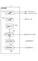
制御装置7の機能的な構成を図2に示す。図2に示すように、制御装置7は機能的には、レーザ出射制御部701と、ステージ移動制御部702と、アクチュエータ制御部703と、集光点演算部704と、端部判断部705と、循環メモリ706(変位記憶手段)と、を備える。レーザ出射制御部701は、加工用レーザ光L1及び測距用レーザ光L2の出射を制御する信号をレーザヘッドユニット3のレーザヘッド13及び対物レンズユニット5のレーザダイオード44にそれぞれ出力する部分である。ステージ移動制御部702は、ステージ2の移動を制御する制御信号をステージ2に出力する部分である。アクチュエータ制御部703はアクチュエータ43の駆動を制御する制御信号を対物レンズユニット5のアクチュエータ43に出力する部分である。アクチュエータ制御部703は循環メモリ706にアクチュエータ43の移動量を格納する部分でもある。この移動量は加工対象物Sの主面S1の変位に応じて変化するので、主面S1の変位を表す量として捉えることもできる。集光点演算部704は対物レンズユニット5の受光部45から出力される非点収差信号に基づいて、加工対象物Sと測距用レーザ光L2の集光点との距離を算出する部分である。端部判断部705は受光部45が受光する光量に基づいて、加工用対物レンズ42が加工対象物Sの端部に対応する位置にあるかどうかを判断する部分である。循環メモリ706は、アクチュエータ43の移動量を格納する循環メモリである。循環メモリ706は64チャネルの格納領域を有しており、それぞれの格納領域に移動量を順次格納する。尚、各機能的構成要素の動作については後述する。 A functional configuration of the
以上のように構成されたレーザ加工装置1によるレーザ加工方法の概要について説明する。まず、ステージ2上に加工対象物Sを載置し、ステージ2を移動させて加工対象物Sの内部に加工用レーザ光L1の集光点Pを合わせる。このステージ2の初期位置は、加工対象物Sの厚さや屈折率、加工用対物レンズ42の開口数等に基づいて決定される。 The outline of the laser processing method by the
続いて、レーザヘッド13から加工用レーザ光L1を出射すると共に、レーザダイオード44から測距用レーザ光L2を出射し、加工用対物レンズ42により集光された加工用レーザ光L1及び測距用レーザ光L2が加工対象物Sの所望のライン(切断予定ライン)上をスキャンするようにステージ2を移動させる。このとき、受光部45により測距用レーザ光L2の反射光が検出され、加工用レーザ光L1の集光点Pの位置が加工対象物Sの表面S1から常に一定の深さとなるようにアクチュエータ43が制御装置7によってフィードバック制御されて、加工用対物レンズ42の位置が軸線β方向に微調整される。 Subsequently, the laser beam L1 for processing is emitted from the
従って、例えば加工対象物Sの表面S1に面振れがあっても、表面S1から一定の深さの位置に多光子吸収による改質領域Rを形成することができる。このように平板状の加工対象物Sの内部にライン状の改質領域Rを形成すると、そのライン状の改質領域Rが起点となって割れが発生し、ライン状の改質領域Rに沿って容易且つ高精度に加工対象物Sを切断することができる。 Therefore, for example, even if the surface S1 of the workpiece S has surface vibration, the modified region R by multiphoton absorption can be formed at a certain depth from the surface S1. When the line-shaped modified region R is formed inside the flat plate-like workpiece S in this way, the line-shaped modified region R starts as a starting point, and cracks are generated. The workpiece S can be cut easily and with high accuracy.
本実施形態のレーザ加工装置1を用いるレーザ加工方法についてより具体的に説明する。このレーザ加工方法の説明では、レーザ加工装置1の動作も併せて説明する。本実施形態のレーザ加工方法は、ウェハ状の加工対象物Sに対する加工用対物レンズ42の初期位置を設定する準備工程と、加工用レーザ光L1を照射して改質領域を形成する加工工程とに分けることができるので、準備工程及び加工工程についてそれぞれ説明する。 A laser processing method using the
(準備工程) まず、ウェハ状の加工対象物Sに対する加工用対物レンズ42の初期位置を設定する準備工程について説明する。 (Preparation process) First, the preparation process which sets the initial position of the
図3は加工対象物Sの平面図である。加工対象物Sにはn本の切断予定ラインC1〜Cnが設定されており、この切断予定ラインC1〜Cnそれぞれで順番にレーザ加工を行う。まず、最初の切断予定ラインC1上の一点Q1において加工対象物Sの内部の所定の位置に集光点が合うようにステージ2(図1参照)の高さを調整する。その調整した高さを初期位置として、切断予定ラインC1の延長上の点X1に加工用対物レンズ42が位置するようにステージ2を移動させる。FIG. 3 is a plan view of the workpiece S. FIG. In the processing object S, n scheduled cutting lines C1 to Cn are set, and laser processing is sequentially performed on each of the scheduled cutting lines C1 to Cn . First, to adjust the height of the
より詳細に図4(A)〜図4(C)を参照しながら説明する。図4(A)〜図4(C)は、図3のII−II断面を示す図である。尚、理解を容易にするために図4(A)〜図4(C)においては断面を示すハッチングを省略する。図4(A)に示すように、加工対象物Sはダイシングフィルム2aを介してステージ2に吸着されて固定されている。ダイシングフィルム2aはダイシングリング(図示しない)で固定されている。 This will be described in more detail with reference to FIGS. 4 (A) to 4 (C). 4 (A) to 4 (C) are cross-sectional views taken along the line II-II in FIG. In addition, in order to make an understanding easy, the hatching which shows a cross section is abbreviate | omitted in FIG. 4 (A)-FIG.4 (C). As shown in FIG. 4A, the workpiece S is adsorbed and fixed to the
図4(A)に示すように、加工対象物2の切断予定ラインC1上の一点Q1に対応する位置に加工用対物レンズ42が配置されるようにステージ2が移動する。加工用対物レンズ42を保持しているアクチュエータ43は最も縮んだ状態から25μm伸びた状態になる。この伸び量25μmは、アクチュエータ43の最大伸び量50μmの半分の量として設定されている。この状態で観察用可視光の反射光のピントが合うようにステージ2を上下させる。尚、ステージ2の上下動による誤差が大きい場合は、まずアクチュエータ43を所望の位置まで動かしてその時の非点収差信号を記憶したら、いったんアクチュエータ43を元の位置まで戻し、ステージ2を(大雑把に)移動させて、アクチュエータ43を先ほど記憶した非点収差信号と合う位置に微調整させると良い。As shown in FIG. 4 (A), the
続いて、図4(B)に示すように、図4(A)の状態からステージ2が更に所定の距離(以下、加工高さ)上昇して、加工対象物Sの表面S1と加工用対物レンズ42との距離が図4(A)における距離から加工高さ分だけ近づくように設定される。ここで、可視域のピント位置とレーザ光の集光位置とが一致するものとすれば、加工用レーザ光L1は、加工対象物Sの内部であって、その表面S1から加工高さと加工対象物Sのレーザ波長における屈折率との積の値に相当する位置に集光されることになる。例えば、加工対象物Sがシリコンウェハであってその屈折率が3.6(波長1.06μm)であり、加工高さが10μmであれば、3.6×10=36μmの位置に集光されることになる。図4(B)に示す状態で測距用レーザ光L2の反射光から非点収差信号を得て、この非点収差信号の値を基準値とする。 Subsequently, as shown in FIG. 4B, the
図4(B)に示す状態からそのままステージ2を移動させて、加工用対物レンズ42が切断予定ラインC1の延長上の点X1に至った段階で図4(C)に示すように待機状態となる。図4(B)及び図4(C)に示す、鉛直方向における加工対象物Sに対する加工用対物レンズ42の位置が初期位置となる。4 as it moves the
この準備工程におけるレーザ加工装置1の動作について図5に示すフローチャートを参照しながら説明する。制御装置7のステージ制御部702がステージ2に対して加工用対物レンズ42がC1上の一点Q1に移動するように制御信号を出力する(ステップS01)。この制御信号の出力に応じてステージ2が移動する。更に制御装置7のアクチュエータ制御部703がアクチュエータ43に対して25μm伸びるように制御信号を出力する(ステップS02)。この制御信号の出力に応じてアクチュエータ43は25μm伸びる。この状態で可視観察光によってピントが合うようにステージ2を上下させ、その可視観察光のピントが合う位置を設定し、加工用対物レンズ42及び加工対象物Sは図4(A)で説明した状態になる(ステップS03)。The operation of the
制御装置7のステージ移動制御部702がステージ2に対して所定の加工高さ(例えば、10μm)上昇するように制御信号を出力する(ステップS04)。この制御信号の出力に応じてステージは10μm上昇し、加工用対物レンズ42及び加工対象物Sは図4(B)で説明した状態になる。 The stage
制御装置7のレーザ出射制御部701はレーザダイオード44に対して測距用レーザ光L2を出射するように制御信号を出力する(ステップS05)。この制御信号の出力に応じてレーザダイオード44は測距用レーザ光L2を出射し、加工対象物Sの表面S1で反射された反射光は受光部45の4分割位置検出素子が受光する。この受光に応じて出力される信号は集光点演算部704及び端部判断部705に出力される。 The laser
集光点演算部704はこの状態における非点収差信号の値を基準値として保持する(ステップS06)。続いて、ステージ移動制御部702からステージ2に対して、加工用対物レンズ42が加工対象物Sの切断予定ラインC1の延長上のX1に対応する位置まで移動するように制御信号を出力する(ステップS07)。この制御信号の出力に応じてステージ2は移動し、加工用対物レンズ42が加工対象物Sの切断予定ラインC1の延長上のX1に対応する位置まで移動すると、ステージ移動制御部702からステージ2に対して移動を停止するように制御信号を出力する(ステップS08)。The condensing
(加工工程) 引き続いて、加工用レーザ光L1及び測距用レーザ光L2を照射して改質領域を形成する加工工程について説明する。 (Processing Step) Subsequently, a processing step of forming the modified region by irradiating the processing laser beam L1 and the distance measuring laser beam L2 will be described.
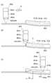
図4(A)〜図4(C)と同様に図3のII−II断面を示す図6(A)〜図6(C)を参照しながら説明する。尚、理解を容易にするために図6(A)〜図6(C)においては断面を示すハッチングを省略する。図6(A)は図4(C)の状態から引き続いて、切断予定ラインC1において加工用対物レンズ42が改質領域の形成を開始した状態を示している。アクチュエータ43は図4(C)で設定された伸び量で固定されている。図4(C)から図6(A)の状態に差し掛かる前に加工用レーザ光L1及び測距用レーザ光L2が照射される。加工用対物レンズ42が図中矢印Eの方向に移動するようにステージ2が移動する。Description will be made with reference to FIGS. 6 (A) to 6 (C) showing the II-II cross section of FIG. 3 as in FIGS. 4 (A) to 4 (C). In order to facilitate understanding, hatching indicating a cross section is omitted in FIGS. 6 (A) to 6 (C). FIG 6 (A) is subsequently from the state of FIG. 4 (C), the processing
測距用レーザ光L2はダイシングフィルム2aにおいては反射率が低く反射される全光量は少ないが、加工対象物Sにおいては反射される全光量が増大する。すなわち、受光部45(図1参照)の4分割位置検出素子が検出する測距用レーザ光L2の反射光の全光量が多くなるので、反射光の全光量が予め定められた閾値を超えた場合に加工対象物Sの切断予定ラインC1と加工用対物レンズ42が交差する位置にあるものと判断できる。従って、受光部45(図1参照)の4分割位置検出素子が検出する全光量が予め定められた閾値よりも大きくなった場合に、加工用対物レンズ42が切断予定ラインC1の一端に相当する位置にあるものとして(図7(A)に相当する状態になってものとして)、その時点でのアクチュエータ43の伸び量の保持を解除して、所定の間隔ごと(例えば、各サンプリングポイントごと)に非点収差信号がステップS06で保持した基準値となるようにアクチュエータ43の伸び量制御を開始する。従って、加工用対物レンズ42が図6(A)中の矢印E方向に移動すると図6(B)に示す状態になる。図6(B)に示すように、区間F(一端部)においては一定の加工高さで改質領域Rが形成されることになる。この区間Fにおいて一定の加工高さで改質領域Rが形成されると、その後、加工用対物レンズ42は切断予定ラインC1に沿って移動し、加工用レーザ光L1によって改質領域Rを形成する。この間、測距用レーザ光L2の反射光から得られる非点収差信号が上記基準値となるようにアクチュエータ43が調整される。The distance measuring laser light L2 has a low reflectivity in the
図6(B)に示す状態から更に加工用対物レンズ42が図6(A)中矢印Eの方向に移動すると、図6(C)に示すように加工用対物レンズ42は切断予定ラインC1の他端に差し掛かる。加工用対物レンズ42が加工対象物Sから外れた位置に至ると、図6(A)を参照しながら説明したのとは逆の状態となり、受光部45(図1参照)の4分割位置検出素子が検出する測距用レーザ光L2の反射光の全光量が少なくなる。従って、受光部45(図1参照)の4分割位置検出素子が検出する全光量が予め定められた閾値よりも小さくなった場合に、加工用対物レンズ42が切断予定ラインC1の一端に相当する位置にあるものとして(図6(C)に相当する状態になってものとして)、その時点でのアクチュエータの伸び量を保持する。アクチュエータ43の伸び量を保持したまま加工用対物レンズ42が図6(C)中のX2の位置に至るようにステージ2が移動し、次の切断予定ラインC2の加工に備える(移行ステップ)。When the processing
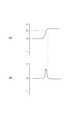
尚、上述の説明で、加工用対物レンズ42が切断予定ラインC1の一端に相当する位置(図6(A))に到達したこと検出するために、受光部45(図1参照)の4分割位置検出素子が検出する全光量が予め定められた閾値よりも大きくなったことに基づいたが、これに限られず他の基準を適用することもできる。その一例を図7(A)〜図7(B)を参照しながら説明する。図7(A)は、縦軸に受光部45(図1参照)の4分割位置検出素子が検出する全光量をとり、横軸に時間をとって、図6(A)〜図6(B)に相当する受光部45(図1参照)の4分割位置検出素子が検出する全光量の変化を記録した図である。この場合には上述の通り、予め定められた閾値T1を上回った時点で加工用対物レンズ42が切断予定ラインC1の一端に相当する位置に到達したと判断している。Note that 4 of the foregoing description, in order to detect it reaches the position where processing
図7(A)のグラフから、所定の間隔ごと(例えば、各サンプリングポイントごと)に、後の全光量の値から前の全光量の値を差し引いた差分の変化量を算出し、縦軸に変化量をとって横軸に時間をとった図を図7(B)に示す。この場合に、正のピークが現れている部分は、全光量の変化が最も大きな点、すなわち加工対象物Sのエッジ中央付近に相当する部分であると考えられる。そこで、図7(A)に示す全光量が閾値T1となった後であって、図7(B)に示す差分のピークの変化が収まった後にアクチュエータ43の追従を開始することもできる。From the graph of FIG. 7A, the change amount of the difference obtained by subtracting the previous total light amount value from the subsequent total light amount value is calculated at predetermined intervals (for example, for each sampling point), and the vertical axis FIG. 7B is a diagram in which the amount of change is taken and time is taken on the horizontal axis. In this case, the portion where the positive peak appears is considered to be the point where the change in the total light amount is the largest, that is, the portion corresponding to the vicinity of the center of the edge of the workpiece S. Therefore, even after the total light quantity shown in FIG. 7 (A) becomes the threshold T1, it is also possible to start the tracking
また、上述の説明で、加工用対物レンズ42が切断予定ラインC1の他端に相当する位置(図6(C))にあること検出するために、受光部45(図1参照)の4分割位置検出素子が検出する全光量が予め定められた閾値よりも小さくなったことに基づいたが、これに限られず他の基準を適用することもできる。その一例を図8(A)〜図8(B)を参照しながら説明する。図8(A)は、縦軸に受光部45(図1参照)の4分割位置検出素子が検出する全光量をとり、横軸に時間をとって、図6(B)〜図6(C)の状態における受光部45(図1参照)の4分割位置検出素子が検出する全光量の変化を記録した図である。この場合には上述の通り、予め定められた閾値T2を下回った時点で加工用対物レンズ42が切断予定ラインC1の一端に相当する位置にあると判断している。Further, in the above description, the position of the processing
図8(A)のグラフから、所定の間隔ごと(例えば、各サンプリングポイントそれぞれ)に、後の全光量の値から前の全光量の値を差し引いた差分の変化量を算出し、縦軸に変化量をとって横軸に時間をとった図を図8(B)に示す。この場合に、負のピークが現れている部分は、全光量の変化が最も大きな点、すなわち加工対象物Sのエッジ(外縁)中央付近に相当する部分であると考えられる。そこで、この部分に相当するアクチュエータ43の伸縮量で固定することもできる。 From the graph of FIG. 8A, the change amount of the difference obtained by subtracting the previous total light amount value from the subsequent total light amount value is calculated at predetermined intervals (for example, each sampling point), and the vertical axis represents FIG. 8B is a diagram in which the amount of change is taken and time is plotted on the horizontal axis. In this case, the portion where the negative peak appears is considered to be a portion corresponding to the point where the change in the total light quantity is the largest, that is, the vicinity of the center of the edge (outer edge) of the workpiece S. Therefore, it can be fixed by the amount of expansion and contraction of the actuator 43 corresponding to this portion.
また、アクチュエータ43の伸縮量は、図8(A)の区間G(全光量が閾値T2を下回った時点でアクチュエータ43の伸縮量を固定した場合)又は区間H(全光量の変化量が負のピークとなった時点でアクチュエータ43の伸縮量を固定した場合)の間において循環メモリ706(図2参照)に格納されている。この循環メモリ706は64チャネル分の循環メモリであるから、例えば最初の5チャネル分のメモリに格納されているアクチュエータ43の伸縮量の平均値を求め、この平均値となるようにアクチュエータ43の伸縮量を固定してもよい。この場合には、図8(A)中の区間G又は区間Hの最初の四分の一の部分に対応する加工対象物Sの主面高さに対応した位置にアクチュエータ43が固定されることになり、次の切断予定ラインC2の初期位置として設定するのにより好適である。Further, the expansion / contraction amount of the
この加工工程におけるレーザ加工装置1の動作について図9に示すフローチャートを参照しながら説明する。尚、レーザ加工装置1のステージ2及び加工用対物レンズ42は、図4(C)を参照しながら説明した状態にあるものとする。 The operation of the
制御部7のレーザ出射制御部701が、レーザヘッド13に対して加工用レーザ光L1を出射するように、レーザダイオード44に対しては測距用レーザ光L2を出射するように、それぞれ制御信号を出力する(ステップS11)。この制御信号の出力に応じて加工用レーザ光L1及び測距用レーザ光L2がそれぞれ出射される。 The control signal is such that the laser
制御装置7のステージ制御部702がステージ2に対して加工用対物レンズ42が図6(A)の矢印E方向に移動するように制御信号を出力する(ステップS12)。この制御信号の出力に応じてステージ2は移動を開始する。 The
制御装置7の端部判断部705は、受光部45から出力される信号に基づいて、加工用対物レンズ42が加工対象物Sの端部に差し掛かったかどうかを判断する(ステップS13)。端部判断部705は、加工用対物レンズ42が加工対象物Sの端部に差し掛かったと判断すると、アクチュエータ制御部703に対してアクチュエータ43の伸縮を開始して、非点収差信号が保持している基準値に等しくなるように、制御信号を出力するように指示する指示信号を出力する。アクチュエータ制御部703はアクチュエータ43に伸縮を開始して、非点収差信号が保持している基準値に等しくなるための、制御信号を出力する(ステップS14)。この制御信号の出力に応じてアクチュエータ43は加工対象物Sの表面S1の変位に応じて伸縮して、測距用レーザ光L2の集光点位置が基準位置となるように加工用対物レンズ42を保持する。従って、加工対象物Sの表面S1の変位に応じた位置に改質領域Rが形成される(図6(B)参照)。 The
端部判断部705は、受光部45から出力される信号に基づいて、加工用対物レンズ42が加工対象物Sの他端に差し掛かったかどうかを判断する(ステップS15)。端部判断部705は、加工用対物レンズ42が加工対象物Sの端部に差し掛かったと判断すると、アクチュエータ制御部703に対してアクチュエータ43の伸縮を停止する制御信号を出力するように指示する指示信号を出力する。この指示信号の出力に応じて、アクチュエータ制御部703はアクチュエータ43に対して伸縮を停止して保持状態とするための制御信号を出力する(ステップS16)。この制御信号の出力に応じてアクチュエータ43は伸縮を停止する。ステージ移動制御部702は、加工用対物レンズ42が切断予定ラインC1の延長線上の点X2に差し掛かると、ステージ2に対して移動を停止するように制御信号を出力する(ステップS17)。その後、循環メモリ706に格納されているアクチュエータ43の伸縮量の内、最初の5チャネル分のメモリに格納されているアクチュエータ43の伸縮量の平均値を算出し、この平均値となるようにアクチュエータ43の伸縮量を固定する(ステップS18)。The
上述した準備工程及び加工工程は、加工対象物Sの全ての切断予定ラインC1〜Cnそれぞれで行われ、切断予定ラインC1〜Cnそれぞれに沿って改質領域Rが形成される。The preparation process and the machining process described above are performed on all the planned cutting lines C1 to Cn of the workpiece S, and the modified region R is formed along each of the planned cutting lines C1 to Cn .
本実施形態では、初期位置に加工用対物レンズ42を保持して加工用レーザ光L1を照射してレーザ加工を開始するので、加工対象物Sの端部の形状変動の影響を極力排除することができる。 In the present embodiment, the processing
加工用対物レンズ42を初期位置に保持した状態で加工対象物Sの端部に改質領域を形成した後に加工用対物レンズ42を保持した状態を解除して、加工用対物レンズ42と加工対象物Sとの距離が一定となるように調整しながら改質領域を形成するので、加工対象物Sの表面S1から一定の距離隔てた位置に改質領域を安定して形成できる。 The state where the processing
改質領域を形成した後に加工用対物レンズ42を加工対象物Sの主面S1に向かう方向に駆動しないように保持するので、次の切断予定ラインの加工に移行する際に円滑な移行が可能となる。 Since the processing
加工用対物レンズ42を駆動しないように保持した時点から所定時間前に記憶したアクチュエータ43の伸縮量に基づいた位置となるように、次の切段予定ラインの準備ステップにおいて加工用対物レンズ42の主面S1に対する位置を設定するので、次の切断予定ラインにおいても加工対象物Sの端部の形状変動による影響を極力排除できる。 In the next preparation step of the planned cutting line, the processing
切断予定ラインに沿って改質領域を安定して形成することができるので、改質領域を形成した後にダイシングフィルム2aの拡張等により加工対象物としてのウエハをチップ状に割断・分離する工程において、良好な切断品質で且つ大量のウエハを割断する場合でも常に安定してウエハの割断を行うことができる。 Since the modified region can be stably formed along the planned cutting line, in the process of cleaving / separating the wafer as the processing object into chips by expanding the
1…レーザ加工装置、2…ステージ、3…レーザヘッドユニット、4…光学系本体部、5…対物レンズユニット、6…レーザ出射装置、7…制御装置、S…加工対象物、R…改質領域、42…加工用対物レンズ、43…アクチュエータ、13…レーザヘッド、44…レーザダイオード、45…受光部。 DESCRIPTION OF
Claims (14)
Translated fromJapanese前記集光点が前記加工対象物内部の所定の位置に合うように設定された前記加工対象物の主面に対する初期位置に前記レンズを保持する準備ステップと、
当該レンズを前記初期位置に保持した状態で前記第一のレーザ光を照射し、前記レンズと前記加工対象物とを前記主面に沿って相対的に移動させて前記切断予定ラインの一端部において改質領域を形成する第一加工ステップと、
前記切断予定ラインの一端部において改質領域が形成された後に前記レンズを前記初期位置に保持した状態を解除し、当該解除後に前記レンズと前記主面との間隔を調整しながら、前記レンズと前記加工対象物とを前記主面に沿って相対的に移動させて改質領域を形成する第二加工ステップと、
を備えるレーザ加工方法。Condensing the first laser beam with a lens and irradiating the inside of the workpiece with a focused point, forming a modified region inside the workpiece along the planned cutting line of the workpiece A laser processing method for
A preparatory step of holding the lens at an initial position with respect to a main surface of the processing object set so that the condensing point matches a predetermined position inside the processing object;
The first laser beam is irradiated with the lens held at the initial position, and the lens and the object to be processed are relatively moved along the main surface, at one end of the planned cutting line. A first processing step to form a modified region;
The state in which the lens is held at the initial position after the modified region is formed at one end portion of the planned cutting line is released, and the lens is adjusted while adjusting the distance between the lens and the main surface after the release. A second processing step of forming a modified region by relatively moving the processing object along the main surface;
A laser processing method comprising:
前記第一のレーザ光と前記主面の変位を測定するための第二のレーザ光とを同一の軸線上で前記加工対象物に向けて前記レンズで集光し、前記主面で反射された前記第二のレーザ光の反射光の光量が所定の閾値を超えた後に前記レンズを保持した状態を解除する、請求項1に記載のレーザ加工方法。In the second processing step,
The first laser beam and the second laser beam for measuring the displacement of the main surface are converged by the lens toward the object to be processed on the same axis and reflected by the main surface. The laser processing method according to claim 1, wherein the state in which the lens is held is released after the amount of reflected light of the second laser light exceeds a predetermined threshold.
前記第一のレーザ光と前記主面の変位を測定するための第二のレーザ光とを同一の軸線上で前記加工対象物に向けて前記レンズで集光し、前記主面で反射された前記第二のレーザ光の反射光の光量の変化量が極大値となった後に前記レンズを保持した状態を解除する、請求項1に記載のレーザ加工方法。In the second processing step,
The first laser beam and the second laser beam for measuring the displacement of the main surface are converged by the lens toward the object to be processed on the same axis and reflected by the main surface. The laser processing method according to claim 1, wherein the state in which the lens is held is released after the amount of change in the amount of reflected light of the second laser light reaches a maximum value.
前記第一の切断予定ラインの第二加工ステップにおいて、前記主面の変位を単位時間帯ごとに順次記憶し、
前記第一の切断予定ラインの移行ステップにおいて、前記レンズの前記主面に対する位置が、前記移行ステップにおいて前記レンズを駆動しないように保持した時点に対応する単位時間帯から所定数前の単位時間帯において記憶した変位に基づいた位置となるように前記レンズを保持し、
前記第二の切断予定ラインの準備ステップにおいては、前記第一の切断予定ラインの移行ステップにおいて前記レンズを保持した位置を初期位置とする、請求項4〜6のいずれか1項に記載のレーザ加工方法。The scheduled cutting line includes a first scheduled cutting line and a second scheduled cutting line,
In the second processing step of the first scheduled cutting line, the displacement of the main surface is sequentially stored for each unit time zone,
In the transition step of the first scheduled cutting line, the position of the lens relative to the main surface is a unit time zone a predetermined number of times before the unit time zone corresponding to the time point when the lens is not driven in the transition step. Holding the lens to a position based on the displacement stored in
The laser according to any one of claims 4 to 6, wherein in the preparation step of the second scheduled cutting line, the position where the lens is held in the transition step of the first scheduled cutting line is set as an initial position. Processing method.
前記第1のレーザ光を前記加工対象物に向けて集光するレンズと、
前記加工対象物と前記レンズとを前記加工対象物の主面に沿って移動させる移動手段と、
前記レンズを前記主面に対して進退自在に保持する保持手段と、
前記移動手段及び前記保持手段それぞれの挙動を制御する制御手段と、
を備え、
前記制御手段は前記集光点が前記加工対象物内部の所定の位置に合う状態となる初期位置に前記レンズを保持するように前記保持手段を制御し、
当該位置に前記レンズを保持した状態で前記第一のレーザ光を照射しながら、前記制御手段は前記加工対象物と前記レンズとを前記主面に沿って相対的に移動させるように前記移動手段を制御して前記切断予定ラインの一端部において改質領域を形成し、
前記切断予定ラインの一端部において改質領域が形成された後に、前記制御手段は前記レンズを前記初期位置に保持した状態を解除して前記レンズと前記主面との間隔を調整しながら保持するように前記保持手段を制御し、前記レンズと前記加工対象物とを前記主面に沿って相対的に移動させるように前記移動手段を制御して改質領域を形成する、
レーザ加工装置。A laser processing apparatus that irradiates a first laser beam with a converging point inside the object to be processed, and forms a modified region inside the object to be processed along a scheduled cutting line of the object to be processed. And
A lens that focuses the first laser beam toward the object to be processed;
Moving means for moving the object to be processed and the lens along a main surface of the object to be processed;
Holding means for holding the lens movably forward and backward with respect to the main surface;
Control means for controlling the behavior of each of the moving means and the holding means;
With
The control means controls the holding means so as to hold the lens at an initial position where the condensing point is in a state of being in a predetermined position inside the workpiece,
While moving the first laser light while holding the lens at the position, the control means moves the processing object and the lens relative to each other along the main surface. To form a modified region at one end of the planned cutting line,
After the modified region is formed at one end portion of the scheduled cutting line, the control means releases the state of holding the lens at the initial position and holds the lens while adjusting the distance between the lens and the main surface. Controlling the holding means to form a modified region by controlling the moving means to move the lens and the object to be processed relatively along the main surface,
Laser processing equipment.
前記制御手段は、前記主面で反射される前記第二のレーザ光の反射光の光量が所定の閾値を超えた後に前記レンズを前記初期位置に保持した状態を解除するように前記保持手段を制御する、請求項8に記載のレーザ加工装置。The lens condenses the first laser beam and the second laser beam for acquiring the displacement of the main surface toward the workpiece on the same axis,
The control means is configured to release the state where the lens is held at the initial position after the amount of reflected light of the second laser light reflected by the main surface exceeds a predetermined threshold. The laser processing apparatus according to claim 8 to be controlled.
前記制御手段は、前記主面で反射される前記第二のレーザ光の反射光の光量の変化量が極大値となった後に前記レンズを前記初期位置に保持した状態を解除するように前記保持手段を制御する、請求項8に記載のレーザ加工装置。The lens condenses the first laser beam and the second laser beam for acquiring the displacement of the main surface toward the workpiece on the same axis,
The control means is configured to release the state where the lens is held at the initial position after the amount of change in the amount of reflected light of the second laser light reflected by the main surface reaches a maximum value. The laser processing apparatus according to claim 8, wherein the means is controlled.
更に、前記制御手段は前記レンズを前記主面に向かう方向に駆動させずに保持するように前記保持手段を制御すると共に、前記レンズと前記加工対象物とを前記主面に沿って相対的に移動させるように前記移動手段を制御する、請求項8〜10のいずれか1項に記載のレーザ加工装置。After the modified region is formed at one end of the planned cutting line, the control means releases the state of holding the lens at the initial position and holds the lens while adjusting the distance between the lens and the main surface. Controlling the holding means to form a modified region by controlling the moving means to relatively move the lens and the object to be processed along the main surface,
Further, the control means controls the holding means so as to hold the lens without being driven in a direction toward the main surface, and relatively moves the lens and the processing object along the main surface. The laser processing apparatus according to claim 8, wherein the moving unit is controlled so as to be moved.
前記制御手段は、前記主面で反射される前記第二のレーザ光の反射光の光量が所定の閾値を下回った後に前記レンズを前記主面に向かう方向に駆動させずに保持するように前記保持手段を制御する、請求項11に記載のレーザ加工装置。The lens focuses the first laser beam and the second laser beam for acquiring the displacement of the main surface toward the object to be processed on the same axis,
The control means holds the lens without driving the lens in a direction toward the main surface after the amount of reflected light of the second laser beam reflected by the main surface falls below a predetermined threshold value. The laser processing apparatus according to claim 11, wherein the holding means is controlled.
前記制御手段は、前記主面で反射される前記第二のレーザ光の反射光の光量の変化量が極小値となった後に前記レンズを前記主面に向かう方向に駆動させずに保持するように前記保持手段を制御する、請求項11に記載のレーザ加工装置。The lens condenses the first laser beam and the second laser beam for acquiring the displacement of the main surface toward the workpiece on the same axis,
The control means holds the lens without driving the lens in the direction toward the main surface after the amount of change in the amount of reflected light of the second laser light reflected by the main surface becomes a minimum value. The laser processing apparatus according to claim 11, wherein the holding unit is controlled.
前記主面の変位を単位時間帯ごとに順次記憶する変位記憶手段を備え、
前記制御手段は、前記第一の切断予定ラインにおいて前記レンズを駆動させずに保持するように制御した時点に対応する単位時間帯から所定数前の単位時間帯において前記変位記憶手段が記憶した変位に基づいた位置を前記第二の切断予定ラインにおける初期位置として設定する、請求項11〜13のいずれか1項に記載のレーザ加工装置。The planned cutting line includes a first planned cutting line and a second planned cutting line,
Displacement storage means for sequentially storing the displacement of the main surface for each unit time zone,
The control means stores the displacement stored in the displacement storage means in a unit time zone a predetermined number of times before the unit time zone corresponding to the time point when the lens is controlled to be held without being driven in the first scheduled cutting line. The laser processing apparatus of any one of Claims 11-13 which sets the position based on this as an initial position in said 2nd cutting plan line.
Priority Applications (13)
| Application Number | Priority Date | Filing Date | Title |
|---|---|---|---|
| JP2004004304AJP4509578B2 (en) | 2004-01-09 | 2004-01-09 | Laser processing method and laser processing apparatus |
| PCT/JP2004/018594WO2005065882A1 (en) | 2004-01-09 | 2004-12-13 | Laser processing method and device |
| KR1020067014200AKR101073183B1 (en) | 2004-01-09 | 2004-12-13 | Laser processing method and device |
| US10/585,343US8624153B2 (en) | 2004-01-09 | 2004-12-13 | Laser processing method and device |
| AT04806955TATE460247T1 (en) | 2004-01-09 | 2004-12-13 | LASER PROCESSING METHOD AND APPARATUS |
| DE602004025981TDE602004025981D1 (en) | 2004-01-09 | 2004-12-13 | LASER PROCESSING METHOD AND DEVICE |
| CNB200480040143XACN100491046C (en) | 2004-01-09 | 2004-12-13 | Laser processing method and laser processing device |
| EP04806955AEP1716960B1 (en) | 2004-01-09 | 2004-12-13 | Laser processing method and device |
| TW094100124ATWI326628B (en) | 2004-01-09 | 2005-01-04 | Laser process in manufacturing method and device thereof |
| MYPI20050077AMY144645A (en) | 2004-01-09 | 2005-01-10 | Laser processing method and laser processing apparatus |
| US14/099,236US9511449B2 (en) | 2004-01-09 | 2013-12-06 | Laser processing method and device |
| US15/255,926US10293433B2 (en) | 2004-01-09 | 2016-09-02 | Laser processing method and device |
| US16/380,660US11241757B2 (en) | 2004-01-09 | 2019-04-10 | Laser processing method and device |
Applications Claiming Priority (1)
| Application Number | Priority Date | Filing Date | Title |
|---|---|---|---|
| JP2004004304AJP4509578B2 (en) | 2004-01-09 | 2004-01-09 | Laser processing method and laser processing apparatus |
Publications (2)
| Publication Number | Publication Date |
|---|---|
| JP2005193284A JP2005193284A (en) | 2005-07-21 |
| JP4509578B2true JP4509578B2 (en) | 2010-07-21 |
Family
ID=34747111
Family Applications (1)
| Application Number | Title | Priority Date | Filing Date |
|---|---|---|---|
| JP2004004304AExpired - LifetimeJP4509578B2 (en) | 2004-01-09 | 2004-01-09 | Laser processing method and laser processing apparatus |
Country Status (10)
| Country | Link |
|---|---|
| US (4) | US8624153B2 (en) |
| EP (1) | EP1716960B1 (en) |
| JP (1) | JP4509578B2 (en) |
| KR (1) | KR101073183B1 (en) |
| CN (1) | CN100491046C (en) |
| AT (1) | ATE460247T1 (en) |
| DE (1) | DE602004025981D1 (en) |
| MY (1) | MY144645A (en) |
| TW (1) | TWI326628B (en) |
| WO (1) | WO2005065882A1 (en) |
Families Citing this family (75)
| Publication number | Priority date | Publication date | Assignee | Title |
|---|---|---|---|---|
| JP4659300B2 (en) | 2000-09-13 | 2011-03-30 | 浜松ホトニクス株式会社 | Laser processing method and semiconductor chip manufacturing method |
| TWI326626B (en) | 2002-03-12 | 2010-07-01 | Hamamatsu Photonics Kk | Laser processing method |
| EP2400539B1 (en) | 2002-03-12 | 2017-07-26 | Hamamatsu Photonics K.K. | Substrate dividing method |
| WO2003076119A1 (en) | 2002-03-12 | 2003-09-18 | Hamamatsu Photonics K.K. | Method of cutting processed object |
| TWI520269B (en) | 2002-12-03 | 2016-02-01 | Hamamatsu Photonics Kk | Cutting method of semiconductor substrate |
| FR2852250B1 (en) | 2003-03-11 | 2009-07-24 | Jean Luc Jouvin | PROTECTIVE SHEATH FOR CANNULA, AN INJECTION KIT COMPRISING SUCH ANKLE AND NEEDLE EQUIPPED WITH SUCH ANKLE |
| DE60315515T2 (en) | 2003-03-12 | 2007-12-13 | Hamamatsu Photonics K.K., Hamamatsu | LASER PROCESSING PROCEDURES |
| CN101862907B (en)* | 2003-07-18 | 2014-01-22 | 浜松光子学株式会社 | Laser beam machining method, laser beam machining apparatus, and laser machined product |
| JP4563097B2 (en) | 2003-09-10 | 2010-10-13 | 浜松ホトニクス株式会社 | Semiconductor substrate cutting method |
| JP4601965B2 (en)* | 2004-01-09 | 2010-12-22 | 浜松ホトニクス株式会社 | Laser processing method and laser processing apparatus |
| JP4598407B2 (en) | 2004-01-09 | 2010-12-15 | 浜松ホトニクス株式会社 | Laser processing method and laser processing apparatus |
| JP4509578B2 (en) | 2004-01-09 | 2010-07-21 | 浜松ホトニクス株式会社 | Laser processing method and laser processing apparatus |
| EP1742253B1 (en) | 2004-03-30 | 2012-05-09 | Hamamatsu Photonics K.K. | Laser processing method |
| KR101109860B1 (en)* | 2004-08-06 | 2012-02-21 | 하마마츠 포토닉스 가부시키가이샤 | Laser processing method, cutting method for work and semiconductor device |
| JP4754801B2 (en) | 2004-10-13 | 2011-08-24 | 浜松ホトニクス株式会社 | Laser processing method |
| JP4762653B2 (en)* | 2005-09-16 | 2011-08-31 | 浜松ホトニクス株式会社 | Laser processing method and laser processing apparatus |
| JP4907965B2 (en)* | 2005-11-25 | 2012-04-04 | 浜松ホトニクス株式会社 | Laser processing method |
| JP4804911B2 (en)* | 2005-12-22 | 2011-11-02 | 浜松ホトニクス株式会社 | Laser processing equipment |
| JP4907984B2 (en) | 2005-12-27 | 2012-04-04 | 浜松ホトニクス株式会社 | Laser processing method and semiconductor chip |
| JP4781128B2 (en)* | 2006-02-24 | 2011-09-28 | 株式会社デンソー | Semiconductor wafer dicing method |
| JP4804183B2 (en)* | 2006-03-20 | 2011-11-02 | 株式会社デンソー | Semiconductor substrate dividing method and semiconductor chip manufactured by the dividing method |
| EP1875983B1 (en) | 2006-07-03 | 2013-09-11 | Hamamatsu Photonics K.K. | Laser processing method and chip |
| JP5183892B2 (en) | 2006-07-03 | 2013-04-17 | 浜松ホトニクス株式会社 | Laser processing method |
| JP4813993B2 (en)* | 2006-07-05 | 2011-11-09 | 株式会社ディスコ | Wafer laser processing method |
| CN101516566B (en)* | 2006-09-19 | 2012-05-09 | 浜松光子学株式会社 | Laser processing method and laser processing apparatus |
| JP4954653B2 (en) | 2006-09-19 | 2012-06-20 | 浜松ホトニクス株式会社 | Laser processing method |
| JP5101073B2 (en)* | 2006-10-02 | 2012-12-19 | 浜松ホトニクス株式会社 | Laser processing equipment |
| JP5132911B2 (en)* | 2006-10-03 | 2013-01-30 | 浜松ホトニクス株式会社 | Laser processing method |
| JP4964554B2 (en)* | 2006-10-03 | 2012-07-04 | 浜松ホトニクス株式会社 | Laser processing method |
| WO2008041604A1 (en)* | 2006-10-04 | 2008-04-10 | Hamamatsu Photonics K.K. | Laser processing method |
| JP5336054B2 (en)* | 2007-07-18 | 2013-11-06 | 浜松ホトニクス株式会社 | Processing information supply system provided with processing information supply device |
| JP5449665B2 (en)* | 2007-10-30 | 2014-03-19 | 浜松ホトニクス株式会社 | Laser processing method |
| JP5094337B2 (en)* | 2007-11-05 | 2012-12-12 | 浜松ホトニクス株式会社 | Laser processing method |
| JP5054496B2 (en)* | 2007-11-30 | 2012-10-24 | 浜松ホトニクス株式会社 | Processing object cutting method |
| JP5134928B2 (en)* | 2007-11-30 | 2013-01-30 | 浜松ホトニクス株式会社 | Workpiece grinding method |
| JP5692969B2 (en) | 2008-09-01 | 2015-04-01 | 浜松ホトニクス株式会社 | Aberration correction method, laser processing method using this aberration correction method, laser irradiation method using this aberration correction method, aberration correction apparatus, and aberration correction program |
| JP5254761B2 (en) | 2008-11-28 | 2013-08-07 | 浜松ホトニクス株式会社 | Laser processing equipment |
| JP5241527B2 (en) | 2009-01-09 | 2013-07-17 | 浜松ホトニクス株式会社 | Laser processing equipment |
| JP5241525B2 (en) | 2009-01-09 | 2013-07-17 | 浜松ホトニクス株式会社 | Laser processing equipment |
| KR101757937B1 (en) | 2009-02-09 | 2017-07-13 | 하마마츠 포토닉스 가부시키가이샤 | Workpiece cutting method |
| JP5639997B2 (en) | 2009-04-07 | 2014-12-10 | 浜松ホトニクス株式会社 | Laser processing equipment |
| JP5491761B2 (en) | 2009-04-20 | 2014-05-14 | 浜松ホトニクス株式会社 | Laser processing equipment |
| DE102010009015A1 (en)* | 2010-02-24 | 2011-08-25 | OSRAM Opto Semiconductors GmbH, 93055 | Method for producing a plurality of optoelectronic semiconductor chips |
| US8722516B2 (en) | 2010-09-28 | 2014-05-13 | Hamamatsu Photonics K.K. | Laser processing method and method for manufacturing light-emitting device |
| DE102011079083A1 (en)* | 2011-07-13 | 2013-01-17 | Trumpf Werkzeugmaschinen Gmbh + Co. Kg | Method for processing a workpiece and a machining device |
| US20140353005A1 (en)* | 2013-06-04 | 2014-12-04 | E I Du Pont De Nemours And Company | Method of making microwave and millimeterwave electronic circuits by laser patterning of unfired low temperature co-fired ceramic (ltcc) substrates |
| WO2015010706A1 (en) | 2013-07-23 | 2015-01-29 | Fraunhofer-Gesellschaft zur Förderung der angewandten Forschung e.V. | Method and device for separating a flat workpiece into multiple parts |
| EP3907570A1 (en) | 2015-02-12 | 2021-11-10 | Glowforge Inc. | Cloud controlled laser fabrication |
| US10509390B2 (en) | 2015-02-12 | 2019-12-17 | Glowforge Inc. | Safety and reliability guarantees for laser fabrication |
| JP6478821B2 (en)* | 2015-06-05 | 2019-03-06 | 株式会社ディスコ | Wafer generation method |
| KR20170087610A (en) | 2016-01-21 | 2017-07-31 | 삼성전자주식회사 | Apparatus for cutting a wafer |
| JP6294378B2 (en) | 2016-03-30 | 2018-03-14 | ファナック株式会社 | Laser processing apparatus and laser processing method provided with pre-processing control unit |
| KR102566170B1 (en)* | 2016-09-12 | 2023-08-10 | 삼성전자주식회사 | Wafer perforating device |
| WO2018098397A1 (en) | 2016-11-25 | 2018-05-31 | Glowforge Inc. | Calibration of computer-numerically-controlled machine |
| WO2018098398A1 (en)* | 2016-11-25 | 2018-05-31 | Glowforge Inc. | Preset optical components in a computer numerically controlled machine |
| US12420355B2 (en) | 2016-11-25 | 2025-09-23 | Glowforge Inc. | Laser fabrication with beam detection |
| JP6955893B2 (en)* | 2017-04-25 | 2021-10-27 | 株式会社ディスコ | Evaluation jig for the height position detection unit of the laser processing device and evaluation method for the height position detection unit of the laser processing device |
| JP7034621B2 (en)* | 2017-07-25 | 2022-03-14 | 浜松ホトニクス株式会社 | Laser processing equipment |
| JP6959073B2 (en)* | 2017-08-30 | 2021-11-02 | 株式会社ディスコ | Laser processing equipment |
| WO2019181063A1 (en)* | 2018-03-20 | 2019-09-26 | 株式会社東京精密 | Laser machining device and laser machining method |
| JP7034551B2 (en)* | 2018-05-15 | 2022-03-14 | 株式会社ディスコ | Processing method of work piece |
| US11897056B2 (en) | 2018-10-30 | 2024-02-13 | Hamamatsu Photonics K.K. | Laser processing device and laser processing method |
| DE112019005413T5 (en) | 2018-10-30 | 2021-07-22 | Hamamatsu Photonics K.K. | Laser processing device and laser processing method |
| JP7120904B2 (en)* | 2018-10-30 | 2022-08-17 | 浜松ホトニクス株式会社 | LASER PROCESSING APPARATUS AND LASER PROCESSING METHOD |
| US10576585B1 (en) | 2018-12-29 | 2020-03-03 | Cree, Inc. | Laser-assisted method for parting crystalline material |
| US11024501B2 (en) | 2018-12-29 | 2021-06-01 | Cree, Inc. | Carrier-assisted method for parting crystalline material along laser damage region |
| US10562130B1 (en) | 2018-12-29 | 2020-02-18 | Cree, Inc. | Laser-assisted method for parting crystalline material |
| JP6758441B2 (en)* | 2019-02-18 | 2020-09-23 | 株式会社アマダ | Laser processing machine, laser processing method, and processing program creation device |
| JP7308396B2 (en)* | 2019-03-11 | 2023-07-14 | 株式会社東京精密 | LASER PROCESSING APPARATUS AND LASER PROCESSING METHOD |
| US10611052B1 (en) | 2019-05-17 | 2020-04-07 | Cree, Inc. | Silicon carbide wafers with relaxed positive bow and related methods |
| TWI857094B (en)* | 2019-07-18 | 2024-10-01 | 日商東京威力科創股份有限公司 | Processing device and processing method |
| JP7582788B2 (en)* | 2020-04-06 | 2024-11-13 | 浜松ホトニクス株式会社 | Laser processing device and laser processing method |
| DE102021109787A1 (en)* | 2021-04-19 | 2022-10-20 | Precitec Gmbh & Co. Kg | Method for comparing laser processing systems and method for monitoring a laser processing process and associated laser processing system |
| CN113546921A (en)* | 2021-07-26 | 2021-10-26 | 贵州电网有限责任公司 | Robot and method for cleaning, derusting and passivating laser metal parts |
| CN116799110B (en)* | 2022-03-01 | 2024-04-26 | 珠海东辉半导体装备有限公司 | Method for removing and repairing Mini LED chip |
Family Cites Families (134)
| Publication number | Priority date | Publication date | Assignee | Title |
|---|---|---|---|---|
| JPS4624989Y1 (en) | 1967-08-31 | 1971-08-28 | ||
| US3629545A (en) | 1967-12-19 | 1971-12-21 | Western Electric Co | Laser substrate parting |
| JPS53145564A (en) | 1977-05-25 | 1978-12-18 | Nec Home Electronics Ltd | Production of semiconductor device |
| US4546231A (en)* | 1983-11-14 | 1985-10-08 | Group Ii Manufacturing Ltd. | Creation of a parting zone in a crystal structure |
| US4562333A (en) | 1984-09-04 | 1985-12-31 | General Electric Company | Stress assisted cutting of high temperature embrittled materials |
| US4769523A (en)* | 1985-03-08 | 1988-09-06 | Nippon Kogaku K.K. | Laser processing apparatus |
| JPH06100711B2 (en) | 1986-05-13 | 1994-12-12 | オリンパス光学工業株式会社 | Automatic focusing device |
| AU585033B2 (en)* | 1986-07-04 | 1989-06-08 | Tosoh Corporation | Quantitative dispenser for a liquid |
| GB2236846B (en)* | 1988-11-22 | 1992-10-14 | Fiat Auto Spa | Laser welding monitoring systems. |
| JPH02185602A (en)* | 1989-01-11 | 1990-07-20 | Mitsubishi Heavy Ind Ltd | Device of measuring rotor blade-to-casing gap |
| US5122648A (en)* | 1990-06-01 | 1992-06-16 | Wyko Corporation | Apparatus and method for automatically focusing an interference microscope |
| JP3024990B2 (en) | 1990-08-31 | 2000-03-27 | 日本石英硝子株式会社 | Cutting method of quartz glass material |
| JPH0639572A (en)* | 1991-01-11 | 1994-02-15 | Souei Tsusho Kk | Wafer cutting device |
| JPH04244910A (en)* | 1991-01-31 | 1992-09-01 | Nec Corp | Height detection device |
| EP0554523B1 (en)* | 1992-02-03 | 1997-04-16 | Matsushita Electric Industrial Co., Ltd. | Laser beam machining apparatus and method for adjusting the height of its condenser lens |
| JP2943499B2 (en) | 1992-04-22 | 1999-08-30 | 日本電気株式会社 | Height measuring method and device |
| JPH06122084A (en) | 1992-10-14 | 1994-05-06 | Nippon Steel Corp | Control method of laser processing device |
| JP3248275B2 (en) | 1992-12-25 | 2002-01-21 | いすゞ自動車株式会社 | Laser processing equipment |
| JP2720744B2 (en) | 1992-12-28 | 1998-03-04 | 三菱電機株式会社 | Laser processing machine |
| JPH0814968B2 (en) | 1993-02-15 | 1996-02-14 | 九州日立マクセル株式会社 | Disk cleaner |
| JP2868384B2 (en) | 1993-02-23 | 1999-03-10 | 株式会社東京精密 | Dicing groove depth measuring method and dicing device |
| US5637244A (en)* | 1993-05-13 | 1997-06-10 | Podarok International, Inc. | Method and apparatus for creating an image by a pulsed laser beam inside a transparent material |
| US5594235A (en)* | 1993-06-17 | 1997-01-14 | Ultrapointe Corporation | Automated surface acquisition for a confocal microscope |
| JPH0740336A (en) | 1993-07-30 | 1995-02-10 | Sumitomo Electric Ind Ltd | Diamond processing method |
| JPH07236985A (en) | 1994-02-28 | 1995-09-12 | Mitsubishi Electric Corp | Laser cutting method and device |
| JP3082124B2 (en) | 1994-07-05 | 2000-08-28 | 株式会社山武 | Electromagnetic flow meter |
| US5622540A (en)* | 1994-09-19 | 1997-04-22 | Corning Incorporated | Method for breaking a glass sheet |
| US5776220A (en)* | 1994-09-19 | 1998-07-07 | Corning Incorporated | Method and apparatus for breaking brittle materials |
| US5543365A (en)* | 1994-12-02 | 1996-08-06 | Texas Instruments Incorporated | Wafer scribe technique using laser by forming polysilicon |
| JP3162254B2 (en) | 1995-01-17 | 2001-04-25 | 三菱電機株式会社 | Laser processing equipment |
| KR100447786B1 (en)* | 1995-08-31 | 2004-11-06 | 코닝 인코포레이티드 | Method and apparatus for brittle material cutting |
| US5624153A (en) | 1995-09-15 | 1997-04-29 | Censullo, Jr.; Mario | Foldable chair |
| KR0171947B1 (en) | 1995-12-08 | 1999-03-20 | 김주용 | Exposure method for manufacturing semiconductor device and exposure device using same |
| JP3660741B2 (en) | 1996-03-22 | 2005-06-15 | 株式会社日立製作所 | Method for manufacturing electronic circuit device |
| IL118030A0 (en)* | 1996-04-25 | 1996-08-04 | Scitex Corp Ltd | A confocal measuring device and method |
| US5883356A (en)* | 1996-05-13 | 1999-03-16 | Tip Engineering Group, Inc. | Laser scoring process and apparatus |
| US5925268A (en) | 1996-06-06 | 1999-07-20 | Engauge Inc. | Laser welding apparatus employing a tilting mechanism and seam follower |
| JP3079042B2 (en)* | 1996-07-19 | 2000-08-21 | 浜松ホトニクス株式会社 | Streak tube sweeping method and sweeping device |
| DK109197A (en)* | 1996-09-30 | 1998-03-31 | Force Instituttet | Process for processing a material by means of a laser beam |
| JPH10163780A (en) | 1996-12-04 | 1998-06-19 | Ngk Insulators Ltd | Manufacturing method of vibrator made of piezoelectric single crystal |
| JPH10189496A (en) | 1996-12-24 | 1998-07-21 | Toshiba Corp | Wafer cutting method and apparatus |
| JPH10202381A (en) | 1997-01-21 | 1998-08-04 | Sumitomo Electric Ind Ltd | Laser cutting equipment |
| JPH10305420A (en)* | 1997-03-04 | 1998-11-17 | Ngk Insulators Ltd | Processing method of base material composed of oxide single crystal and method of manufacturing functional device |
| JPH10288734A (en) | 1997-04-15 | 1998-10-27 | Nikon Corp | Auto focus device |
| DE19728766C1 (en)* | 1997-07-07 | 1998-12-17 | Schott Rohrglas Gmbh | Use of a method for producing a predetermined breaking point in a vitreous body |
| JP3292294B2 (en) | 1997-11-07 | 2002-06-17 | 住友重機械工業株式会社 | Marking method and marking device using laser |
| JP3208730B2 (en) | 1998-01-16 | 2001-09-17 | 住友重機械工業株式会社 | Marking method of light transmissive material |
| JP3449201B2 (en) | 1997-11-28 | 2003-09-22 | 日亜化学工業株式会社 | Method for manufacturing nitride semiconductor device |
| JP3604550B2 (en) | 1997-12-16 | 2004-12-22 | 日亜化学工業株式会社 | Method for manufacturing nitride semiconductor device |
| JP4132172B2 (en) | 1998-02-06 | 2008-08-13 | 浜松ホトニクス株式会社 | Pulse laser processing equipment |
| JPH11345785A (en) | 1998-06-03 | 1999-12-14 | Hitachi Ltd | Dicing method and dicing apparatus |
| JP3152206B2 (en) | 1998-06-19 | 2001-04-03 | 日本電気株式会社 | Autofocus device and autofocus method |
| JP2000015467A (en) | 1998-07-01 | 2000-01-18 | Shin Meiwa Ind Co Ltd | Method and apparatus for processing workpiece by light |
| US6407360B1 (en)* | 1998-08-26 | 2002-06-18 | Samsung Electronics, Co., Ltd. | Laser cutting apparatus and method |
| JP3178524B2 (en)* | 1998-11-26 | 2001-06-18 | 住友重機械工業株式会社 | Laser marking method and apparatus and marked member |
| US6252197B1 (en)* | 1998-12-01 | 2001-06-26 | Accudyne Display And Semiconductor Systems, Inc. | Method and apparatus for separating non-metallic substrates utilizing a supplemental mechanical force applicator |
| US6259058B1 (en)* | 1998-12-01 | 2001-07-10 | Accudyne Display And Semiconductor Systems, Inc. | Apparatus for separating non-metallic substrates |
| US6211488B1 (en)* | 1998-12-01 | 2001-04-03 | Accudyne Display And Semiconductor Systems, Inc. | Method and apparatus for separating non-metallic substrates utilizing a laser initiated scribe |
| US6420678B1 (en)* | 1998-12-01 | 2002-07-16 | Brian L. Hoekstra | Method for separating non-metallic substrates |
| CA2356623C (en)* | 1998-12-23 | 2005-10-18 | Medispectra, Inc. | Systems and methods for optical examination of samples |
| JP2000219528A (en) | 1999-01-18 | 2000-08-08 | Samsung Sdi Co Ltd | Glass substrate cutting method and apparatus |
| JP2000306865A (en) | 1999-02-17 | 2000-11-02 | Toshiba Electronic Engineering Corp | Wafer cutting method and apparatus |
| JP2001093864A (en) | 1999-09-24 | 2001-04-06 | Toshiba Corp | Semiconductor wafer fixing jig and method of manufacturing semiconductor device |
| CN1413136A (en) | 1999-11-24 | 2003-04-23 | 应用光子学公司 | Method and apparatus for separating non-metallic materials |
| JP2001340979A (en) | 2000-03-30 | 2001-12-11 | Toyota Auto Body Co Ltd | Laser processing apparatus |
| US20020006765A1 (en)* | 2000-05-11 | 2002-01-17 | Thomas Michel | System for cutting brittle materials |
| US7049585B2 (en)* | 2000-07-27 | 2006-05-23 | Ebara Corporation | Sheet beam-type testing apparatus |
| JP4659300B2 (en)* | 2000-09-13 | 2011-03-30 | 浜松ホトニクス株式会社 | Laser processing method and semiconductor chip manufacturing method |
| JP5025876B2 (en) | 2000-09-13 | 2012-09-12 | 浜松ホトニクス株式会社 | Laser processing equipment |
| JP4964376B2 (en) | 2000-09-13 | 2012-06-27 | 浜松ホトニクス株式会社 | Laser processing apparatus and laser processing method |
| JP2002107120A (en) | 2000-10-02 | 2002-04-10 | Sumitomo Heavy Ind Ltd | Position detector for surface and rear, and apparatus and method for marking |
| US6720522B2 (en) | 2000-10-26 | 2004-04-13 | Kabushiki Kaisha Toshiba | Apparatus and method for laser beam machining, and method for manufacturing semiconductor devices using laser beam machining |
| JP2002219591A (en) | 2001-01-22 | 2002-08-06 | Toshiba Corp | Laser light irradiation device |
| US6720567B2 (en)* | 2001-01-30 | 2004-04-13 | Gsi Lumonics Corporation | Apparatus and method for focal point control for laser machining |
| US7027155B2 (en) | 2001-03-29 | 2006-04-11 | Gsi Lumonics Corporation | Methods and systems for precisely relatively positioning a waist of a pulsed laser beam and method and system for controlling energy delivered to a target structure |
| JP4803568B2 (en)* | 2001-03-30 | 2011-10-26 | ルネサスエレクトロニクス株式会社 | Inspection apparatus and inspection method for semiconductor integrated circuit |
| US6502381B2 (en) | 2001-04-03 | 2003-01-07 | Clark Crites | Pick-up rake |
| JP2002321080A (en) | 2001-04-24 | 2002-11-05 | Tokyo Instruments Inc | Autofocus device for laser micromachining |
| KR100701013B1 (en) | 2001-05-21 | 2007-03-29 | 삼성전자주식회사 | Method and apparatus for cutting non-metallic substrate using laser beam |
| JP2003002677A (en) | 2001-06-22 | 2003-01-08 | Seiko Epson Corp | Laser cleaving support table, laser cleaving apparatus, laser cleaving method, and liquid crystal panel manufacturing method |
| JP3918583B2 (en) | 2002-03-01 | 2007-05-23 | 株式会社デンソー | High density energy processing apparatus and high density energy processing method |
| WO2003076119A1 (en)* | 2002-03-12 | 2003-09-18 | Hamamatsu Photonics K.K. | Method of cutting processed object |
| EP2400539B1 (en) | 2002-03-12 | 2017-07-26 | Hamamatsu Photonics K.K. | Substrate dividing method |
| TWI326626B (en)* | 2002-03-12 | 2010-07-01 | Hamamatsu Photonics Kk | Laser processing method |
| US6580054B1 (en)* | 2002-06-10 | 2003-06-17 | New Wave Research | Scribing sapphire substrates with a solid state UV laser |
| US7469160B2 (en)* | 2003-04-18 | 2008-12-23 | Banks Perry S | Methods and apparatus for evaluating image focus |
| TWI520269B (en)* | 2002-12-03 | 2016-02-01 | Hamamatsu Photonics Kk | Cutting method of semiconductor substrate |
| EP1588793B1 (en)* | 2002-12-05 | 2012-03-21 | Hamamatsu Photonics K.K. | Laser processing devices |
| JP2004188422A (en)* | 2002-12-06 | 2004-07-08 | Hamamatsu Photonics Kk | Device and method for machining laser beam |
| US7341007B2 (en) | 2003-03-05 | 2008-03-11 | Joel Vatsky | Balancing damper |
| FR2852250B1 (en) | 2003-03-11 | 2009-07-24 | Jean Luc Jouvin | PROTECTIVE SHEATH FOR CANNULA, AN INJECTION KIT COMPRISING SUCH ANKLE AND NEEDLE EQUIPPED WITH SUCH ANKLE |
| DE60315515T2 (en)* | 2003-03-12 | 2007-12-13 | Hamamatsu Photonics K.K., Hamamatsu | LASER PROCESSING PROCEDURES |
| JP2004337902A (en) | 2003-05-14 | 2004-12-02 | Hamamatsu Photonics Kk | Laser beam machining device and laser beam machining method |
| JP2004337903A (en) | 2003-05-14 | 2004-12-02 | Hamamatsu Photonics Kk | Laser beam machining device and laser beam machining method |
| CN101862907B (en)* | 2003-07-18 | 2014-01-22 | 浜松光子学株式会社 | Laser beam machining method, laser beam machining apparatus, and laser machined product |
| JP4563097B2 (en)* | 2003-09-10 | 2010-10-13 | 浜松ホトニクス株式会社 | Semiconductor substrate cutting method |
| JP2005086175A (en) | 2003-09-11 | 2005-03-31 | Hamamatsu Photonics Kk | Method of manufacturing semiconductor thin film, semiconductor thin film, semiconductor thin-film chip, electron tube and light detector |
| EP1705764B1 (en)* | 2004-01-07 | 2012-11-14 | Hamamatsu Photonics K. K. | Semiconductor light-emitting device and its manufacturing method |
| JP4601965B2 (en)* | 2004-01-09 | 2010-12-22 | 浜松ホトニクス株式会社 | Laser processing method and laser processing apparatus |
| JP4509578B2 (en) | 2004-01-09 | 2010-07-21 | 浜松ホトニクス株式会社 | Laser processing method and laser processing apparatus |
| JP4598407B2 (en) | 2004-01-09 | 2010-12-15 | 浜松ホトニクス株式会社 | Laser processing method and laser processing apparatus |
| JP3708104B2 (en)* | 2004-01-13 | 2005-10-19 | 浜松ホトニクス株式会社 | Laser processing method and laser processing apparatus |
| KR101336402B1 (en)* | 2004-03-30 | 2013-12-04 | 하마마츠 포토닉스 가부시키가이샤 | Laser processing method and semiconductor chip |
| JP4536407B2 (en)* | 2004-03-30 | 2010-09-01 | 浜松ホトニクス株式会社 | Laser processing method and object to be processed |
| EP1742253B1 (en)* | 2004-03-30 | 2012-05-09 | Hamamatsu Photonics K.K. | Laser processing method |
| JP4634089B2 (en)* | 2004-07-30 | 2011-02-16 | 浜松ホトニクス株式会社 | Laser processing method |
| KR101109860B1 (en)* | 2004-08-06 | 2012-02-21 | 하마마츠 포토닉스 가부시키가이샤 | Laser processing method, cutting method for work and semiconductor device |
| JP4754801B2 (en)* | 2004-10-13 | 2011-08-24 | 浜松ホトニクス株式会社 | Laser processing method |
| JP4781661B2 (en)* | 2004-11-12 | 2011-09-28 | 浜松ホトニクス株式会社 | Laser processing method |
| JP4917257B2 (en)* | 2004-11-12 | 2012-04-18 | 浜松ホトニクス株式会社 | Laser processing method |
| JP4198123B2 (en)* | 2005-03-22 | 2008-12-17 | 浜松ホトニクス株式会社 | Laser processing method |
| JP4776994B2 (en)* | 2005-07-04 | 2011-09-21 | 浜松ホトニクス株式会社 | Processing object cutting method |
| JP4749799B2 (en)* | 2005-08-12 | 2011-08-17 | 浜松ホトニクス株式会社 | Laser processing method |
| JP4762653B2 (en)* | 2005-09-16 | 2011-08-31 | 浜松ホトニクス株式会社 | Laser processing method and laser processing apparatus |
| JP4237745B2 (en)* | 2005-11-18 | 2009-03-11 | 浜松ホトニクス株式会社 | Laser processing method |
| JP4907965B2 (en)* | 2005-11-25 | 2012-04-04 | 浜松ホトニクス株式会社 | Laser processing method |
| JP4804911B2 (en)* | 2005-12-22 | 2011-11-02 | 浜松ホトニクス株式会社 | Laser processing equipment |
| JP4907984B2 (en) | 2005-12-27 | 2012-04-04 | 浜松ホトニクス株式会社 | Laser processing method and semiconductor chip |
| JP5183892B2 (en)* | 2006-07-03 | 2013-04-17 | 浜松ホトニクス株式会社 | Laser processing method |
| EP1875983B1 (en)* | 2006-07-03 | 2013-09-11 | Hamamatsu Photonics K.K. | Laser processing method and chip |
| CN101516566B (en)* | 2006-09-19 | 2012-05-09 | 浜松光子学株式会社 | Laser processing method and laser processing apparatus |
| JP4954653B2 (en)* | 2006-09-19 | 2012-06-20 | 浜松ホトニクス株式会社 | Laser processing method |
| JP5101073B2 (en)* | 2006-10-02 | 2012-12-19 | 浜松ホトニクス株式会社 | Laser processing equipment |
| JP5132911B2 (en)* | 2006-10-03 | 2013-01-30 | 浜松ホトニクス株式会社 | Laser processing method |
| JP4964554B2 (en)* | 2006-10-03 | 2012-07-04 | 浜松ホトニクス株式会社 | Laser processing method |
| WO2008041604A1 (en)* | 2006-10-04 | 2008-04-10 | Hamamatsu Photonics K.K. | Laser processing method |
| JP5336054B2 (en)* | 2007-07-18 | 2013-11-06 | 浜松ホトニクス株式会社 | Processing information supply system provided with processing information supply device |
| JP4402708B2 (en)* | 2007-08-03 | 2010-01-20 | 浜松ホトニクス株式会社 | Laser processing method, laser processing apparatus and manufacturing method thereof |
| JP5225639B2 (en)* | 2007-09-06 | 2013-07-03 | 浜松ホトニクス株式会社 | Manufacturing method of semiconductor laser device |
| JP5342772B2 (en)* | 2007-10-12 | 2013-11-13 | 浜松ホトニクス株式会社 | Processing object cutting method |
| JP5449665B2 (en)* | 2007-10-30 | 2014-03-19 | 浜松ホトニクス株式会社 | Laser processing method |
| JP5134928B2 (en) | 2007-11-30 | 2013-01-30 | 浜松ホトニクス株式会社 | Workpiece grinding method |
| JP5054496B2 (en) | 2007-11-30 | 2012-10-24 | 浜松ホトニクス株式会社 | Processing object cutting method |
| JP5241525B2 (en) | 2009-01-09 | 2013-07-17 | 浜松ホトニクス株式会社 | Laser processing equipment |
- 2004
- 2004-01-09JPJP2004004304Apatent/JP4509578B2/ennot_activeExpired - Lifetime
- 2004-12-13DEDE602004025981Tpatent/DE602004025981D1/ennot_activeExpired - Lifetime
- 2004-12-13ATAT04806955Tpatent/ATE460247T1/ennot_activeIP Right Cessation
- 2004-12-13WOPCT/JP2004/018594patent/WO2005065882A1/enactiveApplication Filing
- 2004-12-13USUS10/585,343patent/US8624153B2/enactiveActive
- 2004-12-13KRKR1020067014200Apatent/KR101073183B1/ennot_activeExpired - Lifetime
- 2004-12-13CNCNB200480040143XApatent/CN100491046C/ennot_activeExpired - Lifetime
- 2004-12-13EPEP04806955Apatent/EP1716960B1/ennot_activeExpired - Lifetime
- 2005
- 2005-01-04TWTW094100124Apatent/TWI326628B/ennot_activeIP Right Cessation
- 2005-01-10MYMYPI20050077Apatent/MY144645A/enunknown
- 2013
- 2013-12-06USUS14/099,236patent/US9511449B2/ennot_activeExpired - Lifetime
- 2016
- 2016-09-02USUS15/255,926patent/US10293433B2/enactiveActive
- 2019
- 2019-04-10USUS16/380,660patent/US11241757B2/enactiveActive
Also Published As
| Publication number | Publication date |
|---|---|
| WO2005065882A1 (en) | 2005-07-21 |
| EP1716960A1 (en) | 2006-11-02 |
| CN100491046C (en) | 2009-05-27 |
| US20160368085A1 (en) | 2016-12-22 |
| US20080218735A1 (en) | 2008-09-11 |
| EP1716960B1 (en) | 2010-03-10 |
| CN1902023A (en) | 2007-01-24 |
| MY144645A (en) | 2011-10-31 |
| US20140097163A1 (en) | 2014-04-10 |
| TWI326628B (en) | 2010-07-01 |
| KR101073183B1 (en) | 2011-10-12 |
| TW200539979A (en) | 2005-12-16 |
| US11241757B2 (en) | 2022-02-08 |
| US9511449B2 (en) | 2016-12-06 |
| JP2005193284A (en) | 2005-07-21 |
| US20190232422A1 (en) | 2019-08-01 |
| US8624153B2 (en) | 2014-01-07 |
| KR20070031271A (en) | 2007-03-19 |
| US10293433B2 (en) | 2019-05-21 |
| EP1716960A4 (en) | 2008-08-13 |
| DE602004025981D1 (en) | 2010-04-22 |
| ATE460247T1 (en) | 2010-03-15 |
Similar Documents
| Publication | Publication Date | Title |
|---|---|---|
| JP4509578B2 (en) | Laser processing method and laser processing apparatus | |
| JP4598407B2 (en) | Laser processing method and laser processing apparatus | |
| JP4601965B2 (en) | Laser processing method and laser processing apparatus |
Legal Events
| Date | Code | Title | Description |
|---|---|---|---|
| A621 | Written request for application examination | Free format text:JAPANESE INTERMEDIATE CODE: A621 Effective date:20061226 | |
| TRDD | Decision of grant or rejection written | ||
| A01 | Written decision to grant a patent or to grant a registration (utility model) | Free format text:JAPANESE INTERMEDIATE CODE: A01 Effective date:20100427 | |
| A01 | Written decision to grant a patent or to grant a registration (utility model) | Free format text:JAPANESE INTERMEDIATE CODE: A01 | |
| A61 | First payment of annual fees (during grant procedure) | Free format text:JAPANESE INTERMEDIATE CODE: A61 Effective date:20100428 | |
| FPAY | Renewal fee payment (event date is renewal date of database) | Free format text:PAYMENT UNTIL: 20130514 Year of fee payment:3 | |
| R150 | Certificate of patent or registration of utility model | Ref document number:4509578 Country of ref document:JP Free format text:JAPANESE INTERMEDIATE CODE: R150 Free format text:JAPANESE INTERMEDIATE CODE: R150 | |
| FPAY | Renewal fee payment (event date is renewal date of database) | Free format text:PAYMENT UNTIL: 20130514 Year of fee payment:3 | |
| FPAY | Renewal fee payment (event date is renewal date of database) | Free format text:PAYMENT UNTIL: 20140514 Year of fee payment:4 | |
| EXPY | Cancellation because of completion of term |