JP4505815B2 - Orthodontic appliance - Google Patents
Orthodontic applianceDownload PDFInfo
- Publication number
- JP4505815B2 JP4505815B2JP2005209524AJP2005209524AJP4505815B2JP 4505815 B2JP4505815 B2JP 4505815B2JP 2005209524 AJP2005209524 AJP 2005209524AJP 2005209524 AJP2005209524 AJP 2005209524AJP 4505815 B2JP4505815 B2JP 4505815B2
- Authority
- JP
- Japan
- Prior art keywords
- inner part
- slot
- opening
- wire
- socket
- Prior art date
- Legal status (The legal status is an assumption and is not a legal conclusion. Google has not performed a legal analysis and makes no representation as to the accuracy of the status listed.)
- Expired - Fee Related
Links
Images


Classifications
- A—HUMAN NECESSITIES
- A61—MEDICAL OR VETERINARY SCIENCE; HYGIENE
- A61C—DENTISTRY; APPARATUS OR METHODS FOR ORAL OR DENTAL HYGIENE
- A61C7/00—Orthodontics, i.e. obtaining or maintaining the desired position of teeth, e.g. by straightening, evening, regulating, separating, or by correcting malocclusions
- A61C7/12—Brackets; Arch wires; Combinations thereof; Accessories therefor
- A61C7/28—Securing arch wire to bracket
- A61C7/285—Locking by rotation
Landscapes
- Health & Medical Sciences (AREA)
- Oral & Maxillofacial Surgery (AREA)
- Dentistry (AREA)
- Epidemiology (AREA)
- Life Sciences & Earth Sciences (AREA)
- Animal Behavior & Ethology (AREA)
- General Health & Medical Sciences (AREA)
- Public Health (AREA)
- Veterinary Medicine (AREA)
- Dental Tools And Instruments Or Auxiliary Dental Instruments (AREA)
Description
Translated fromJapanese本発明は歯列矯正装置に関する。The present invention relates to an orthodontic apparatus.
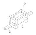
従来の歯列矯正装置として、ワイヤ80を挿入するための横溝72を有するブラケットの前方に縦溝73を形成し、縦溝73に薄板状のスライド部材71を挿入したものが存在する(図11および12、特許文献1参照)。スライド部材71は縦溝73に沿って上下方向に移動可能であり、スライド部材71を下方に移動すると横溝72が閉じられてワイヤ80が保持される。
しかし、スライド部材71が薄板状であるから強度が乏しいと共に、スライド部材71の正面側の殆どの部分が正面方向に露出しているため外力を受け易く、外力を受けたときに破損する恐れがある。However, since the
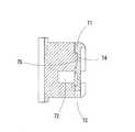
また、スライド部材71の裏面に僅かに窪んだ凹部74を形成し、ブラケットの前面に僅かに突出した凸部75を形成して、前記凹部74に前記凸部75が浅く係止していることから、外力が作用したときに係止が解けてスライド部材71が外れる恐れがあり、スライド部材71が外れた場合はワイヤ80をブラケット内に保持できない。Also, a
また、可及的にスライド部材71が外れる恐れを低くするために、スプリング部材の弾性力によってスライド部材71の係止状態を維持しようとするものもあるが、スプリング部材をブラケット内部の前後方向に向けて内蔵するため、複雑な構造になってしまうので好ましくない(特許文献1の図18参照)。In addition, in order to reduce the possibility of the
そこで、本発明は、複雑な構造ではなくシンプルな構造によって、ワイヤを保持できる歯列矯正装置を提供することを目的とする。Then, an object of this invention is to provide the orthodontic apparatus which can hold | maintain a wire with a simple structure instead of a complicated structure.
本発明は、上下に対向するアーム部で形成されたスロットを有するブラケットと、ワイヤを保持するためのソケットを有するインナーパーツとを備え、アーム部によって挟持されるようにインナーパーツをスロットに挿入してスロットの開口を塞ぐようにしており、インナーパーツは、スロットに挿入される基部の外周面に一端を接続した連結部を有し、上下のアーム部間に形成されたスロットの開口を、前記連結部が左右に移動するための空間とすることで、インナーパーツを左右方向に移動させてスロットに挿入できるとともに、アーム部に形成された縦スリットを、前記連結部が上下に移動するための空間とすることで、インナーパーツを回動させて、スロットの開口がインナーパーツのソケットを除いた他の部分に塞がれた状態にできるようにしたことを特徴とする歯列矯正装置である。The present invention includes a bracket having a slot formed by upper and lower arm portions and an inner part having a socket for holding a wire, and the inner part is inserted into the slot so as to be sandwiched by the arm portion.has an openingslots infarctionGuyo Te, the inner part has a connection portion having one end connected to the outer peripheral surface of the base portion to be inserted into the slot, the opening of the slots formed between the upper and lower arm portions, By providing a space for the connecting portion to move left and right, the inner part can be moved in the left-right direction and inserted into the slot, and the connecting portion moves up and down the vertical slit formed in the arm portion. By rotating the inner part, the slot opening is blocked by other parts except the socket of the inner part. A orthodontic device being characterized inthat the so that.
本発明によると、ブラケットに形成されたスロットに対して、ソケットを有するインナーパーツを挿入するという簡易な構造によって、スロットの開口を塞いでワイヤを確実に保持できる。構造が簡易であるから、施術上も取扱い易く、また、装置全体の体積を小さくできる。また、上下に対向するアーム部に挟持されるインナーパーツを備えているから、インナーパーツは安定した状態で挿入されるので、スロットの開口を塞いだ状態を安定的に維持でき、ワイヤを確実に保持できる。また、上下に対向するアーム部で形成されるスロットに挿入される形状のインナーパーツであるから十分な強度を備える。According to thepresent invention , a simple structure in which an inner part having a socket is inserted into a slot formed in a bracket, the opening of the slot can be closed and the wire can be securely held. Since the structure is simple, it is easy to handle in terms of treatment, and the volume of the entire apparatus can be reduced. In addition, since the inner parts are sandwiched between the upper and lower arm parts, the inner parts are inserted in a stable state, so that the state where the slot opening is blocked can be stably maintained, and the wire is securely Can hold. Moreover, since it is an inner part of the shape inserted in the slot formed by the arm part which opposes up and down, it has sufficient intensity | strength.
また、インナーパーツのソケットが、底部と両側面で構成され、両側面が外方に広がるようにして開口を形成しているものとすることができる。Moreover, the socket of an inner part shall be comprised by the bottom part and both side surfaces, and shall form the opening so that both side surfaces may spread outward.
さらに、インナーパーツの連結部の他端にハンドル部を形成したものとすることができる。Further, a handle portion may be formed atthe other end ofthe connecting portion of the inner part.
スロットやインナーパーツは微小なものであるから施術も難しいが、インナーパーツにハンドル部を形成することにより、ハンドル部をつかんでインナーパーツを扱うことができるようになると、インナーパーツの取扱いが容易になり、施術も容易になる。Treatment is difficult because the slot and inner parts are very small, but by forming the handle part on the inner part, it becomes easy to handle the inner part when you can grasp the handle part and handle the inner part. The treatment is also easy.
本発明によると、簡易な構造によってワイヤを確実に保持できる。構造が簡易であるから、施術上も取扱い易く、また、装置全体の体積を小さくできる。また、インナーパーツは安定した状態で挿入されるので、スロットの開口を塞いだ状態を安定的に維持でき、ワイヤを確実に保持できる。また、十分な強度も備えている。According to thepresent invention , the wire can be reliably held with a simple structure. Since the structure is simple, it is easy to handle in terms of treatment, and the volume of the entire apparatus can be reduced. Further, since the inner part is inserted in a stable state, the state in which the opening of the slot is blocked can be stably maintained, and the wire can be securely held. It also has sufficient strength.
以下、本発明を実施するための最良の形態を、実施例として示す各図と共に説明する。DESCRIPTION OF THE PREFERRED EMBODIMENTS The best mode for carrying out the present invention will be described below with reference to the drawings shown as examples.
実施例1を図1〜4に示す。Example 1 is shown in FIGS.
実施例1に係る歯列矯正装置は、ブラケット10と、ブラケット10に挿入されるインナーパーツ20によって構成される。The orthodontic apparatus according to the first embodiment includes a
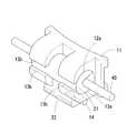
ブラケット10は、図1を参照して、歯面に取り付けられるベース部11と、ベース部11の表面から前方に向けて突出する上アーム部12と、同じくベース部11の表面から前方に向けて突出する下アーム部13とを有する。Referring to FIG. 1, the
ベース部11は、ブラケット10を接着剤等で歯面に取り付けるためのものであり、ベース部11の裏面に形成された凸部は歯面とブラケット10との接着を補助するものである。The
上アーム部12は、下アーム部13と共にインナーパーツ20を挿入するためのスロット30を形成する。具体的には、上アーム部12の円弧面12aと下アーム部の円弧面13aが対向することにより、略円柱状の空間であるスロット30を形成する。The
上アーム部12は鉤状であって、図3に示すように、上アーム部12の先端はインナーパーツ20の外周面を覆うように曲っている。また、下アーム部13も鉤状であって、先端はインナーパーツ20の外周面を覆うように曲がっている。具体的には、上アーム部12の下面の殆どが半円状の円弧面12aで形成され、下アーム部13の上面は殆どが半円状の円弧面13aで形成されており、両者が対向して略円柱状のスロット30を形成する。このスロット30にインナーパーツ20が挿入されると、インナーパーツ20は上アーム部12の円弧面12aと下アーム部13の円弧面13aの両者によって挟持される。なお、スロット30の左右幅とインナーパーツ20の左右幅は略同一である。The
このようにして構成されたスロット30であると、インナーパーツ20が安定的に挟持されるので、上記従来例と比較して、インナーパーツ20がブラケット10から外れる恐れが少ない。また、上記従来例に比較して、インナーパーツ20が正面方向に対して露出する部分が少ないので、外力による影響は小さく、破損の危険性が少ない。When the
上アーム部12の先端には平坦面12bが形成される。また、下アーム部13の先端にも平坦面13bが形成される。上アーム部12の平坦面12bと下アーム部13の平坦面13bとが対向して、スロット30の開口32を形成する。開口32はインナーパーツ20の連結部23が左右に移動するための空間である。また、ワイヤ40をスロット30に差し込むための空間でもある。なお、開口32の上下幅は連結部23の厚み(d)にほぼ等しい。A
上アーム部12及び下アーム部13の左右方向の中央には縦スリット31が形成される。具体的には、上アーム部12及び下アーム部13には、それぞれを二分するように縦方向に切り欠いた縦スリット31が形成される。縦スリット31はインナーパーツ20の連結部23が上下に移動するための空間である。なお、縦スリット31の左右幅は連結部23の横幅(W)にほぼ等しい。A
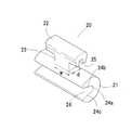
スロット30に挿入されるインナーパーツ20は、図2を参照して、基部21と、ハンドル部22と、基部21とハンドル部22とを連結する連結部23を有する。The
基部21はスロット30に挿入されるため、スロット30の形状に合わせて成形される。すなわち、基部21はスロットに嵌合できるような形状に成形される。本実施例の場合、スロット30は略円柱状であるから、インナーパーツ20の基部21は円柱の一部を切り欠いた略円柱状に成形される。このような形状のインナーパーツ20であると、前記従来例のような薄板状のスライド部材に比較して、断面係数が大きく強度が高い。よって、外力を受けたときに破損する危険性が少ない。Since the
また、基部21はワイヤ40を保持するためのものであり、断面丸形のワイヤ40を保持するソケット24を有する。ソケット24は基部21の一部を切り欠いて形成され、基部21内にワイヤ40を納めるための空間となる。本実施例において、ソケット24を形成した基部21は断面形状が略C形となり、外方に向いて開口を形成する。具体的には、ソケット24は底部24aと側面24b、24cで構成され、底部24aは円弧面であり、側面24b、24cは平坦面である。両側面24b、24cが外方に広がるように傾斜して開口を形成する。この開口からワイヤ40が差し込まれる。The
ハンドル部22は基部21に連結されている。具体的には、基部21の外周面に連結部23の一端を接続し、連結部23の他端をハンドル部22に接続している。ハンドル部22には凹部25が形成される。この凹部25は、連結部23の方向に開口しており、ハンドル部22が下方に回動したときに、下アーム部13の裏面に形成された凸部14と係止する。The
ブラケット10とインナーパーツ20の各構成は上記のとおりであり、両者は次のようにして組み立てられる。Each structure of the
インナーパーツ20の円弧面からなる外周面とスロット30の円弧面12a、13aとが合致するように両者を左右方向に相対させ、且つ、スロット30の開口32と連結部23とが合致するように配置して、インナーパーツ20を左右方向に移動させてスロット30に挿入してゆく。連結部23が縦スリット31に位置するところで左右方向の移動を停止し、ハンドル部22を上方向に移動させてインナーパーツ20を回動させる。そうすると、図3のとおり、開口32とインナーパーツ20のソケット24の開口が略一致した状態になる。この状態において、開口32からワイヤ40を差し込むと、開口32とソケット24の開口が一致しているので、ワイヤ40はソケット24の底部24aに到達する。The outer peripheral surface formed by the arc surface of the
ワイヤ40をソケット24に差し込んだ後、ハンドル部22を下方向に移動させてインナーパーツ20を再び回動させる。インナーパーツ20が回動すると、ソケット24の開口がスロット30の開口32から離れてゆき、両者は一致しなくなる。そうすると、図4のとおり、開口32は、インナーパーツ20のソケット24を除いた他の部分(ソケット24に対向する反対部分)によって塞がれた状態となる。このようにして、ワイヤ40がブラケット10に保持される。After inserting the
このとき、ハンドル部22の凹部25は下アーム部13の凸部14に係止して、インナーパーツ20がワイヤ40を保持した状態を維持している。また、縦スリット31内に連結部23が位置しているので、インナーパーツ20は左右方向にも移動しない。このようにして、より確実にワイヤ40を保持する状態が維持される。At this time, the
なお、上記の説明では、インナーパーツ20を取り付けた後にワイヤ40を差し込んだが、逆に、ワイヤ40を差し込んだ後でインナーパーツ20を挿入することも当然に可能である。In the above description, the
ブラケット10およびインナーパーツ20の材質は、歯科用の金属、合成材料、セラミック、合成樹脂などである。合成樹脂としては、たとえば、ポリメチルメタクリレート、ポリオキシメチレン、ポリカーカーボネイト、ポリプロピレン、ポリエチレン、ポリエチレンナフタレートなどが挙げられる。なお、従来の歯列矯正装置に場合、強度的な問題から金属製のものが多かったが、本発明は簡易な構造であるため小型化が可能であって、且つ十分な強度も備えているので、必ずしも金属で製造する必要がなく、プラスチックやセラミックなどで製造できる。また、前記のとおり、簡易な構造であるため小型化が可能であるから、歯面に取り付けても目立たず、審美的に優れている。そして、患者に与える心理的ないし物理的抵抗も少なくできるので好ましい。The material of the
なお、ブラケット10は、横約2.8〜3.5mm、縦約2.5mm、奥行約2.0mmである。ベース部11の厚さは0.45mm、上(下)アーム部の基端側の厚み(縦方向)は約0.1mm、先端側の厚み(縦方向)は0.25mmである。また、縦スリットの横幅は約0.8mmであり、スロット30の開口32の縦幅は0.7mmである。また、円柱状のスロット30の直径は約1.3mmであり、左右長は約2.5〜3.2mmである。また、インナーパーツ20の略円柱状の基部21の直径は約1.3mmであり、連結部の縦幅(d)は約0.7mm、横幅(w)は約0.8mmである。ソケットの溝深さは約0.9mmである。また、ワイヤ40の直径は約0.012〜0.020インチである。The
〔参考例〕
参考例を図1、5〜10に示す。[Reference example]
Reference examples are shown in FIGS.
参考例は、ブラケット10とインナーパーツ50とからなる。参考例において、ブラケット10は実施例1と同様の構成であるが、インナーパーツ50に特徴がある。The reference example includes the
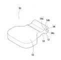
インナーパーツ50は、図5に示すとおり、基部51と、ハンドル部52と、連結部53とを有する。インナーパーツ50の基部51はスロット30に挿入されるため、スロット30の形状に合わせて成形される。本実施例の場合、スロット30は略円柱状であるから、基部51も円柱の一部を切り欠いて略円柱状に成形される。一部を切り欠いた略円柱状の基部51は断面矩形状のワイヤ60を保持するためのソケット54を形成する。ソケット54の形状は矩形状のワイヤ60の形状に合致するように形成される。具体的には、図8等を参照して、互いに対向する側面54b、54cと側面54b、54cに直交する底面54aで構成される。なお、参考例において、ワイヤの形状は多角形であれば良く、特に本実施例の図面に記載された形状そのものに限る趣旨ではない。As shown in FIG. 5, the
ソケット54の開口方向(角度)は適宜に選択される。所望のトルクやローテーション応じてソケット54の開口角度を選択するのである。たとえば、図8〜10に示すように、基部51の中心(円の中心)と連結部53の中央を貫く軸線Lに対する底面54aの中央を底面54aに対して垂直に貫く軸線L´の傾斜角を0°、5°、10°などのように設定して選択する。このようなものであると、ソケット54の開口方向の角度に応じたトルクをかけることができる。歯面にトルクを与えるとき、それぞれ異なる角度を設けたインナーパーツ(ソケット)を用意しておけば、ブラケットを変更する必要はなく、インナーパーツのみを変更すれば所望のトルクをかけることができるので、ワイヤの装着に比較的時間を要せず、施術時間が短縮できる。The opening direction (angle) of the
ハンドル部52はインナーパーツ50の取扱いを容易にするものであり、連結部53を介して基部51に連結している。ハンドル部52はインナーパーツ50をスロット30内に挿入する際に利用する。大きさは横幅約8.0mm、縦幅約7.0mmである。なお、後述するとおり、ハンドル部52は切断して基部51から切り離される。The
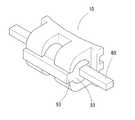
次に、ブラケット10とインナーパーツ50の組み立てについて説明する。
スロット30に矩形状の断面を有するワイヤ60を差込み、次いで、インナーパーツ50をスロット30に挿入する。具体的には、スロット30の開口32からワイヤ60を差込んだ後、インナーパーツ50の円弧状の外周とスロット30の円弧状の内面(円弧面12a、円弧面13a)とが合致するように両者を相対させて、且つ、開口32と連結部53とが合致するように配置して、インナーパーツ50をスロット30に左右方向に移動して挿入してゆく。図6のように、インナーパーツ50の全体がスロット30内に収まった状態で、ハンドル部52を切断する。ハンドル部52を切り取ったインナーパーツ50は、基部51と連結部53とからなり、図7に示すように、スロット30の開口32に連結部53が位置して、開口32を塞ぐようになる。このとき、インナーパーツ50(連結部53)は、上アーム部12の12bと下アーム部13の13bによって挟持されるため、上下方向に回動(移動)せず、この状態によって歯にトルクがかかる。Next, assembly of the
A
なお、ハンドル部52の横幅は約8.0mmであり、縦幅は約7.0mmである。また、ワイヤ60の寸法は適宜選択するものであり、例えば、縦0.016mm×横0.022mm、縦0.018mm×横0.025mm、縦0.021mm×横0.025mm、縦0.017mm×横0.017mm等の角状のワイヤである。The
10 ブラケット
12 上アーム部
13 下アーム部
20 インナーパーツ
22 ハンドル部
24 ソケット
30 スロット
32 スロットの開口
40、60 ワイヤ
DESCRIPTION OF
Claims (3)
Translated fromJapaneseThe orthodontic apparatus according to claim 1 or 2, wherein a handle portion is formed atthe other end ofthe connecting portion of the inner parts.
Priority Applications (5)
| Application Number | Priority Date | Filing Date | Title |
|---|---|---|---|
| JP2005209524AJP4505815B2 (en) | 2005-07-20 | 2005-07-20 | Orthodontic appliance |
| US11/996,090US8272867B2 (en) | 2005-07-20 | 2006-07-14 | Orthodontic device |
| PCT/JP2006/314064WO2007010856A1 (en) | 2005-07-20 | 2006-07-14 | Orthodontic device |
| EP06768224AEP1908432A1 (en) | 2005-07-20 | 2006-07-14 | Orthodontic device |
| US13/506,633US9232988B2 (en) | 2005-07-20 | 2012-05-05 | Orthodontic device |
Applications Claiming Priority (1)
| Application Number | Priority Date | Filing Date | Title |
|---|---|---|---|
| JP2005209524AJP4505815B2 (en) | 2005-07-20 | 2005-07-20 | Orthodontic appliance |
Publications (2)
| Publication Number | Publication Date |
|---|---|
| JP2007020981A JP2007020981A (en) | 2007-02-01 |
| JP4505815B2true JP4505815B2 (en) | 2010-07-21 |
Family
ID=37668737
Family Applications (1)
| Application Number | Title | Priority Date | Filing Date |
|---|---|---|---|
| JP2005209524AExpired - Fee RelatedJP4505815B2 (en) | 2005-07-20 | 2005-07-20 | Orthodontic appliance |
Country Status (4)
| Country | Link |
|---|---|
| US (1) | US8272867B2 (en) |
| EP (1) | EP1908432A1 (en) |
| JP (1) | JP4505815B2 (en) |
| WO (1) | WO2007010856A1 (en) |
Families Citing this family (23)
| Publication number | Priority date | Publication date | Assignee | Title |
|---|---|---|---|---|
| ITFI20070069A1 (en)* | 2007-03-22 | 2008-09-23 | Leone Spa | ORTHODONTIC ATTACK |
| FI121776B (en)* | 2009-03-10 | 2011-04-15 | Tuomo Kantomaa | Bracket for teeth and arrangement for tooth regulation |
| US8162660B2 (en) | 2009-11-20 | 2012-04-24 | Robert T Rudman | Rotating clip orthodontic bracket |
| US9566134B2 (en)* | 2010-02-20 | 2017-02-14 | World Class Technology Corporation | Orthodontic applicance with radiused wire slot |
| US9517112B2 (en)* | 2010-02-20 | 2016-12-13 | World Class Technology Corporation | Low profile bracket with elastomeric chain |
| JP2013121367A (en)* | 2010-03-23 | 2013-06-20 | Dentsply Sankin Kk | Orthodontic bracket structure, and method for moving the same |
| KR200465146Y1 (en) | 2011-03-15 | 2013-02-06 | 김석필 | Orthodontic bracket |
| KR101327925B1 (en)* | 2011-12-20 | 2013-11-13 | 김미경 | Self-ligating lingual bracket |
| JP2014027992A (en)* | 2012-07-31 | 2014-02-13 | Chikami Miltec Inc | Orthodontic force adjustment system |
| KR101356942B1 (en)* | 2012-08-21 | 2014-01-29 | 조선대학교산학협력단 | Orthodontic bracket |
| KR101299811B1 (en)* | 2013-02-08 | 2013-08-23 | 이종호 | Non-wing orthodontic bracket |
| US9949806B2 (en) | 2013-03-15 | 2018-04-24 | Christopher C. Cosse | Orthodontic bracket assemblies with torque-adjusting drums |
| JP6391681B2 (en) | 2013-06-14 | 2018-09-19 | オルムコ コーポレイション | Self-ligating orthodontic bracket with rotatable closure member |
| US9655694B2 (en) | 2013-12-06 | 2017-05-23 | Christopher C. Cosse | Adjustable-prescription orthodontic bracket assemblies |
| US9999481B2 (en) | 2013-12-06 | 2018-06-19 | Christopher C. Cosse | Adjustable-prescription orthodontic bracket assemblies |
| KR101379618B1 (en)* | 2014-01-28 | 2014-03-31 | 김중한 | Ring bracket for orthodontics |
| CN107174359A (en)* | 2016-03-10 | 2017-09-19 | 常州宁新医疗科技有限公司 | A kind of abnormal correction system of the prefabricated arch wire deflection of accurate conduction and preparation method thereof |
| BR112018008610A2 (en)* | 2016-03-21 | 2018-10-30 | World Class Tech Corporation | orthodontic appliance with elastomeric chain |
| US11246681B2 (en) | 2017-06-22 | 2022-02-15 | Christopher C. Cosse | Adjustable-prescription orthodontic brackets |
| US11166789B2 (en)* | 2018-09-26 | 2021-11-09 | Christopher C. Cosse | Adjustable-prescription orthodontic bracket assemblies |
| US11911237B2 (en)* | 2020-09-24 | 2024-02-27 | Carlos F. Rocklin | Dental aligner apparatus |
| KR102455440B1 (en)* | 2021-11-16 | 2022-10-18 | 주식회사 지앤드아이 | rotation roller type self-ligating orthodontic bracket assembly with interchangeable wire seating block |
| KR102600768B1 (en)* | 2022-11-08 | 2023-11-09 | 이은승 | Gap filling member for orthodonic braces |
Family Cites Families (13)
| Publication number | Priority date | Publication date | Assignee | Title |
|---|---|---|---|---|
| US4077126A (en)* | 1976-07-06 | 1978-03-07 | Pletcher Erwin Carroll | Orthodontic bracket |
| US4419078A (en)* | 1981-05-20 | 1983-12-06 | Pletcher Erwin Carroll | Orthodontic bracket |
| US4371337A (en)* | 1981-05-20 | 1983-02-01 | Pletcher Erwin Carroll | Orthodontic bracket |
| US4559012A (en)* | 1984-12-06 | 1985-12-17 | Pletcher Erwin Carroll | Orthodontic bracket |
| JPS61103111U (en)* | 1984-12-13 | 1986-07-01 | ||
| US4551094A (en)* | 1985-01-31 | 1985-11-05 | Kesling Peter C | Edgewise bracket wire retaining clip |
| US5094614A (en)* | 1991-03-08 | 1992-03-10 | Wildman Alexander J | Miniature self-locking labial bracket |
| JPH04309346A (en)* | 1991-04-09 | 1992-10-30 | Tomy Kk | Dental orthodontic appliance |
| US5224858A (en)* | 1992-01-28 | 1993-07-06 | Hamilton Ortho Inc. | Orthodontic brackets and arch wires for use in combination therewith |
| US5322435A (en)* | 1992-07-23 | 1994-06-21 | Pletcher Erwin Carroll | Orthodontic bracket |
| WO2002064051A1 (en)* | 2001-02-15 | 2002-08-22 | Norbert Abels | Self-ligating orthodontic brackets having a rigid bracket base and deformable ligation cover |
| DE10238730A1 (en) | 2002-08-23 | 2004-03-04 | Framatome Anp Gmbh | Process for cleaning the steam generator of a pressurized water reactor |
| US7033170B2 (en)* | 2004-05-11 | 2006-04-25 | Mark Andrew Cordato | Orthodontic bracket and clip |
- 2005
- 2005-07-20JPJP2005209524Apatent/JP4505815B2/ennot_activeExpired - Fee Related
- 2006
- 2006-07-14USUS11/996,090patent/US8272867B2/ennot_activeExpired - Fee Related
- 2006-07-14WOPCT/JP2006/314064patent/WO2007010856A1/enactiveApplication Filing
- 2006-07-14EPEP06768224Apatent/EP1908432A1/ennot_activeWithdrawn
Also Published As
| Publication number | Publication date |
|---|---|
| EP1908432A1 (en) | 2008-04-09 |
| JP2007020981A (en) | 2007-02-01 |
| WO2007010856A1 (en) | 2007-01-25 |
| US8272867B2 (en) | 2012-09-25 |
| US20090130621A1 (en) | 2009-05-21 |
Similar Documents
| Publication | Publication Date | Title |
|---|---|---|
| JP4505815B2 (en) | Orthodontic appliance | |
| USD574614S1 (en) | Card holder | |
| EP3206840B1 (en) | Holder for objects | |
| USD493484S1 (en) | Writing instrument | |
| KR101538007B1 (en) | Bracket for othodontic treatment | |
| USD486858S1 (en) | Writing instrument with clip ornament | |
| USD485300S1 (en) | Writing instrument with clip ornament | |
| US20060140395A1 (en) | Method for assembling clip for electronic device retainer and connecting structure of the clip | |
| KR20060108676A (en) | Interdental brush | |
| USD533225S1 (en) | Writing instrument | |
| TW201418771A (en) | Loupe with stand | |
| ES2339589T3 (en) | INTERDENTAL BRUSH. | |
| USD540586S1 (en) | Tissue holder | |
| USD547578S1 (en) | Bottle holder | |
| USD524814S1 (en) | Label area of flash memory drive | |
| USD456990S1 (en) | Drill bit organizer | |
| ES2942460T3 (en) | Universal support for a telecommunications terminal | |
| CN108685554B (en) | Cleaning tool | |
| US9232988B2 (en) | Orthodontic device | |
| USD500090S1 (en) | Certificate holder | |
| KR102682745B1 (en) | Dental screwdriver device | |
| JP5466517B2 (en) | Rotating clasp | |
| JP7065524B2 (en) | Penlight holder for helmet | |
| USD485726S1 (en) | DVD holder | |
| FR2710830A1 (en) | Orthodontic bracket with adjustable housing |
Legal Events
| Date | Code | Title | Description |
|---|---|---|---|
| A621 | Written request for application examination | Free format text:JAPANESE INTERMEDIATE CODE: A621 Effective date:20061107 | |
| A131 | Notification of reasons for refusal | Free format text:JAPANESE INTERMEDIATE CODE: A131 Effective date:20091113 | |
| A521 | Request for written amendment filed | Free format text:JAPANESE INTERMEDIATE CODE: A523 Effective date:20100107 | |
| TRDD | Decision of grant or rejection written | ||
| A01 | Written decision to grant a patent or to grant a registration (utility model) | Free format text:JAPANESE INTERMEDIATE CODE: A01 Effective date:20100401 | |
| A01 | Written decision to grant a patent or to grant a registration (utility model) | Free format text:JAPANESE INTERMEDIATE CODE: A01 | |
| A61 | First payment of annual fees (during grant procedure) | Free format text:JAPANESE INTERMEDIATE CODE: A61 Effective date:20100415 | |
| FPAY | Renewal fee payment (event date is renewal date of database) | Free format text:PAYMENT UNTIL: 20130514 Year of fee payment:3 | |
| R150 | Certificate of patent or registration of utility model | Ref document number:4505815 Country of ref document:JP Free format text:JAPANESE INTERMEDIATE CODE: R150 Free format text:JAPANESE INTERMEDIATE CODE: R150 | |
| FPAY | Renewal fee payment (event date is renewal date of database) | Free format text:PAYMENT UNTIL: 20140514 Year of fee payment:4 | |
| R250 | Receipt of annual fees | Free format text:JAPANESE INTERMEDIATE CODE: R250 | |
| R250 | Receipt of annual fees | Free format text:JAPANESE INTERMEDIATE CODE: R250 | |
| R250 | Receipt of annual fees | Free format text:JAPANESE INTERMEDIATE CODE: R250 | |
| R250 | Receipt of annual fees | Free format text:JAPANESE INTERMEDIATE CODE: R250 | |
| R250 | Receipt of annual fees | Free format text:JAPANESE INTERMEDIATE CODE: R250 | |
| R250 | Receipt of annual fees | Free format text:JAPANESE INTERMEDIATE CODE: R250 | |
| LAPS | Cancellation because of no payment of annual fees |