JP4504332B2 - Surgical system and system operation information notification method - Google Patents
Surgical system and system operation information notification methodDownload PDFInfo
- Publication number
- JP4504332B2 JP4504332B2JP2006162918AJP2006162918AJP4504332B2JP 4504332 B2JP4504332 B2JP 4504332B2JP 2006162918 AJP2006162918 AJP 2006162918AJP 2006162918 AJP2006162918 AJP 2006162918AJP 4504332 B2JP4504332 B2JP 4504332B2
- Authority
- JP
- Japan
- Prior art keywords
- output
- electrical energy
- output status
- unit
- model
- Prior art date
- Legal status (The legal status is an assumption and is not a legal conclusion. Google has not performed a legal analysis and makes no representation as to the accuracy of the status listed.)
- Expired - Fee Related
Links
Images


Classifications
- A—HUMAN NECESSITIES
- A61—MEDICAL OR VETERINARY SCIENCE; HYGIENE
- A61B—DIAGNOSIS; SURGERY; IDENTIFICATION
- A61B1/00—Instruments for performing medical examinations of the interior of cavities or tubes of the body by visual or photographical inspection, e.g. endoscopes; Illuminating arrangements therefor
- A61B1/04—Instruments for performing medical examinations of the interior of cavities or tubes of the body by visual or photographical inspection, e.g. endoscopes; Illuminating arrangements therefor combined with photographic or television appliances
- A61B1/045—Control thereof
- A—HUMAN NECESSITIES
- A61—MEDICAL OR VETERINARY SCIENCE; HYGIENE
- A61B—DIAGNOSIS; SURGERY; IDENTIFICATION
- A61B17/00—Surgical instruments, devices or methods
- A61B17/00234—Surgical instruments, devices or methods for minimally invasive surgery
- A—HUMAN NECESSITIES
- A61—MEDICAL OR VETERINARY SCIENCE; HYGIENE
- A61B—DIAGNOSIS; SURGERY; IDENTIFICATION
- A61B90/00—Instruments, implements or accessories specially adapted for surgery or diagnosis and not covered by any of the groups A61B1/00 - A61B50/00, e.g. for luxation treatment or for protecting wound edges
- A61B90/90—Identification means for patients or instruments, e.g. tags
- A61B90/98—Identification means for patients or instruments, e.g. tags using electromagnetic means, e.g. transponders
- G—PHYSICS
- G16—INFORMATION AND COMMUNICATION TECHNOLOGY [ICT] SPECIALLY ADAPTED FOR SPECIFIC APPLICATION FIELDS
- G16H—HEALTHCARE INFORMATICS, i.e. INFORMATION AND COMMUNICATION TECHNOLOGY [ICT] SPECIALLY ADAPTED FOR THE HANDLING OR PROCESSING OF MEDICAL OR HEALTHCARE DATA
- G16H20/00—ICT specially adapted for therapies or health-improving plans, e.g. for handling prescriptions, for steering therapy or for monitoring patient compliance
- G16H20/40—ICT specially adapted for therapies or health-improving plans, e.g. for handling prescriptions, for steering therapy or for monitoring patient compliance relating to mechanical, radiation or invasive therapies, e.g. surgery, laser therapy, dialysis or acupuncture
- G—PHYSICS
- G16—INFORMATION AND COMMUNICATION TECHNOLOGY [ICT] SPECIALLY ADAPTED FOR SPECIFIC APPLICATION FIELDS
- G16H—HEALTHCARE INFORMATICS, i.e. INFORMATION AND COMMUNICATION TECHNOLOGY [ICT] SPECIALLY ADAPTED FOR THE HANDLING OR PROCESSING OF MEDICAL OR HEALTHCARE DATA
- G16H30/00—ICT specially adapted for the handling or processing of medical images
- G16H30/20—ICT specially adapted for the handling or processing of medical images for handling medical images, e.g. DICOM, HL7 or PACS
- G—PHYSICS
- G16—INFORMATION AND COMMUNICATION TECHNOLOGY [ICT] SPECIALLY ADAPTED FOR SPECIFIC APPLICATION FIELDS
- G16H—HEALTHCARE INFORMATICS, i.e. INFORMATION AND COMMUNICATION TECHNOLOGY [ICT] SPECIALLY ADAPTED FOR THE HANDLING OR PROCESSING OF MEDICAL OR HEALTHCARE DATA
- G16H40/00—ICT specially adapted for the management or administration of healthcare resources or facilities; ICT specially adapted for the management or operation of medical equipment or devices
- G16H40/60—ICT specially adapted for the management or administration of healthcare resources or facilities; ICT specially adapted for the management or operation of medical equipment or devices for the operation of medical equipment or devices
- G16H40/63—ICT specially adapted for the management or administration of healthcare resources or facilities; ICT specially adapted for the management or operation of medical equipment or devices for the operation of medical equipment or devices for local operation
- A—HUMAN NECESSITIES
- A61—MEDICAL OR VETERINARY SCIENCE; HYGIENE
- A61B—DIAGNOSIS; SURGERY; IDENTIFICATION
- A61B18/00—Surgical instruments, devices or methods for transferring non-mechanical forms of energy to or from the body
- A61B18/04—Surgical instruments, devices or methods for transferring non-mechanical forms of energy to or from the body by heating
- A61B18/12—Surgical instruments, devices or methods for transferring non-mechanical forms of energy to or from the body by heating by passing a current through the tissue to be heated, e.g. high-frequency current
- A61B18/14—Probes or electrodes therefor
- A61B18/1402—Probes for open surgery
- A—HUMAN NECESSITIES
- A61—MEDICAL OR VETERINARY SCIENCE; HYGIENE
- A61B—DIAGNOSIS; SURGERY; IDENTIFICATION
- A61B18/00—Surgical instruments, devices or methods for transferring non-mechanical forms of energy to or from the body
- A61B18/04—Surgical instruments, devices or methods for transferring non-mechanical forms of energy to or from the body by heating
- A61B18/12—Surgical instruments, devices or methods for transferring non-mechanical forms of energy to or from the body by heating by passing a current through the tissue to be heated, e.g. high-frequency current
- A61B18/14—Probes or electrodes therefor
- A61B18/1442—Probes having pivoting end effectors, e.g. forceps
- A61B18/1445—Probes having pivoting end effectors, e.g. forceps at the distal end of a shaft, e.g. forceps or scissors at the end of a rigid rod
- A—HUMAN NECESSITIES
- A61—MEDICAL OR VETERINARY SCIENCE; HYGIENE
- A61B—DIAGNOSIS; SURGERY; IDENTIFICATION
- A61B17/00—Surgical instruments, devices or methods
- A61B2017/00017—Electrical control of surgical instruments
- A61B2017/00199—Electrical control of surgical instruments with a console, e.g. a control panel with a display
- A—HUMAN NECESSITIES
- A61—MEDICAL OR VETERINARY SCIENCE; HYGIENE
- A61B—DIAGNOSIS; SURGERY; IDENTIFICATION
- A61B17/00—Surgical instruments, devices or methods
- A61B2017/00017—Electrical control of surgical instruments
- A61B2017/00221—Electrical control of surgical instruments with wireless transmission of data, e.g. by infrared radiation or radiowaves
- A—HUMAN NECESSITIES
- A61—MEDICAL OR VETERINARY SCIENCE; HYGIENE
- A61B—DIAGNOSIS; SURGERY; IDENTIFICATION
- A61B17/00—Surgical instruments, devices or methods
- A61B17/32—Surgical cutting instruments
- A61B17/320068—Surgical cutting instruments using mechanical vibrations, e.g. ultrasonic
- A61B17/320092—Surgical cutting instruments using mechanical vibrations, e.g. ultrasonic with additional movable means for clamping or cutting tissue, e.g. with a pivoting jaw
- A61B2017/320093—Surgical cutting instruments using mechanical vibrations, e.g. ultrasonic with additional movable means for clamping or cutting tissue, e.g. with a pivoting jaw additional movable means performing cutting operation
- A—HUMAN NECESSITIES
- A61—MEDICAL OR VETERINARY SCIENCE; HYGIENE
- A61B—DIAGNOSIS; SURGERY; IDENTIFICATION
- A61B17/00—Surgical instruments, devices or methods
- A61B17/32—Surgical cutting instruments
- A61B17/320068—Surgical cutting instruments using mechanical vibrations, e.g. ultrasonic
- A61B17/320092—Surgical cutting instruments using mechanical vibrations, e.g. ultrasonic with additional movable means for clamping or cutting tissue, e.g. with a pivoting jaw
- A61B2017/320095—Surgical cutting instruments using mechanical vibrations, e.g. ultrasonic with additional movable means for clamping or cutting tissue, e.g. with a pivoting jaw with sealing or cauterizing means
- A—HUMAN NECESSITIES
- A61—MEDICAL OR VETERINARY SCIENCE; HYGIENE
- A61B—DIAGNOSIS; SURGERY; IDENTIFICATION
- A61B18/00—Surgical instruments, devices or methods for transferring non-mechanical forms of energy to or from the body
- A61B2018/00988—Means for storing information, e.g. calibration constants, or for preventing excessive use, e.g. usage, service life counter
- A—HUMAN NECESSITIES
- A61—MEDICAL OR VETERINARY SCIENCE; HYGIENE
- A61B—DIAGNOSIS; SURGERY; IDENTIFICATION
- A61B18/00—Surgical instruments, devices or methods for transferring non-mechanical forms of energy to or from the body
- A61B18/04—Surgical instruments, devices or methods for transferring non-mechanical forms of energy to or from the body by heating
- A61B18/12—Surgical instruments, devices or methods for transferring non-mechanical forms of energy to or from the body by heating by passing a current through the tissue to be heated, e.g. high-frequency current
- A61B18/14—Probes or electrodes therefor
- A61B2018/1405—Electrodes having a specific shape
- A61B2018/1407—Loop
- A—HUMAN NECESSITIES
- A61—MEDICAL OR VETERINARY SCIENCE; HYGIENE
- A61B—DIAGNOSIS; SURGERY; IDENTIFICATION
- A61B18/00—Surgical instruments, devices or methods for transferring non-mechanical forms of energy to or from the body
- A61B18/04—Surgical instruments, devices or methods for transferring non-mechanical forms of energy to or from the body by heating
- A61B18/12—Surgical instruments, devices or methods for transferring non-mechanical forms of energy to or from the body by heating by passing a current through the tissue to be heated, e.g. high-frequency current
- A61B18/14—Probes or electrodes therefor
- A61B2018/1405—Electrodes having a specific shape
- A61B2018/1422—Hook
- A—HUMAN NECESSITIES
- A61—MEDICAL OR VETERINARY SCIENCE; HYGIENE
- A61B—DIAGNOSIS; SURGERY; IDENTIFICATION
- A61B34/00—Computer-aided surgery; Manipulators or robots specially adapted for use in surgery
- A61B34/10—Computer-aided planning, simulation or modelling of surgical operations
Landscapes
- Health & Medical Sciences (AREA)
- Engineering & Computer Science (AREA)
- Life Sciences & Earth Sciences (AREA)
- Surgery (AREA)
- Public Health (AREA)
- General Health & Medical Sciences (AREA)
- Medical Informatics (AREA)
- Nuclear Medicine, Radiotherapy & Molecular Imaging (AREA)
- Biomedical Technology (AREA)
- Animal Behavior & Ethology (AREA)
- Molecular Biology (AREA)
- Veterinary Medicine (AREA)
- Heart & Thoracic Surgery (AREA)
- Pathology (AREA)
- Epidemiology (AREA)
- Primary Health Care (AREA)
- Radiology & Medical Imaging (AREA)
- Oral & Maxillofacial Surgery (AREA)
- Physics & Mathematics (AREA)
- Urology & Nephrology (AREA)
- Optics & Photonics (AREA)
- Electromagnetism (AREA)
- Biophysics (AREA)
- Business, Economics & Management (AREA)
- General Business, Economics & Management (AREA)
- Endoscopes (AREA)
- Medical Treatment And Welfare Office Work (AREA)
- Surgical Instruments (AREA)
Description
Translated fromJapanese本発明は、複数の医療機器を制御する手術システム及びそのシステム稼働情報告知方法に関する。 The present invention relates to a surgical system that controls a plurality of medical devices and a system operation information notification method thereof.
近年、複数の医療機器を制御して手技を行う手術システムとして、例えば内視鏡を用いて手技を行う内視鏡手術システムが広く普及し、用いられる医療機器も多岐に及んでいる。 2. Description of the Related Art In recent years, for example, an endoscopic surgery system that performs a procedure using an endoscope has been widely used as a surgery system that performs a procedure by controlling a plurality of medical devices, and a wide variety of medical devices are used.
このような内視鏡手術システムで用いられる医療機器は、電子内視鏡システムの他に、電気メス装置、超音波装置、気腹装置等を備えており、例えば特開2003−76786号公報あるいは特開2003−70746号公報に提案されているように、これらの機器が一括システムとして管理され、システムコントローラ下に配置された操作機器により制御される。 A medical device used in such an endoscopic surgery system includes an electric scalpel device, an ultrasonic device, a pneumoperitoneum device, and the like in addition to an electronic endoscope system. For example, Japanese Patent Application Laid-Open No. 2003-76786 or As proposed in Japanese Patent Laid-Open No. 2003-70746, these devices are managed as a collective system and controlled by operating devices arranged under the system controller.
一方、特開2005−65721号公報においては、手術システムとして、手術時に発生するすべての情報を、その発生順に記録すると共に表示装置に表示し、該情報を補完して事後の分析等に活用可能な医療情報システムが開示されている。この医療情報システムは、術後に手術の経過を詳細に分析し、手術法や器具の改良に関する情報を得ており、特に目的とする手術に対して最適な手順を確立することを念頭に置いている。
しかしながら、従来の手術システム、例えば特開2005−65721号公報の医療情報システム等は、術中に発生する情報を記録するが、各医療機器の情報記録のタイミングを記録しているだけで、手技中の各医療機器の詳細な制御状態を監視することができず、効果的に手技分析を行うことができないといった問題がある。 However, conventional surgical systems, such as the medical information system disclosed in Japanese Patent Application Laid-Open No. 2005-65721, record information generated during the operation, but only record the timing of information recording of each medical device. Therefore, there is a problem that the detailed control state of each medical device cannot be monitored and the technique analysis cannot be performed effectively.
本発明は、上記事情に鑑みてなされたものであり、処置具の使用者(術者等)に対し、該処置具の種類及び使用状況に応じた適切な対応を促すことが可能な手術システム及びそのシステム稼働情報告知方法を提供することを目的としている。The present invention has been made in view of the above circumstances, and is a surgical systemcapable of prompting a user (such as an operator) of a treatment tool to take an appropriate response according to the type and use status of the treatment tool. And it aims at providing the system operation information notification method.
本発明の手術システムは、
医療処置装置から電気的エネルギーを供給され、該供給された電気的エネルギーにより患部を処置する処置具と、
前記患部に対する処置に使用される前記処置具の種別を識別する処置具種別識別手段と、
前記医療処置装置からの電気的エネルギーの出力状況に関する複数のモデルパターンが前記処置具の種別毎に予め記憶されたモデルパターン記憶手段と、
前記複数のモデルパターンに対応した対応情報が前記処置具の種別毎に予め記憶された対応情報記憶手段と、
前記医療処置装置からの電気的エネルギーの出力状況を検知する出力状況検知手段と、
前記出力状況検知手段が検知した、前記医療処置装置からの電気的エネルギーの出力状況を記録する出力状況記録手段と、
前記処置具種別識別手段の識別結果と、前記出力状況記録手段に記録された電気的エネルギーの出力状況と、に基づいて前記モデルパターン記憶手段に記憶された前記複数のモデルパターンから一のモデルパターンを選択するとともに、該一のモデルパターンに対応する前記対応情報を前記対応情報記憶手段から抽出する分析手段と、
を備えて構成される。The surgical system of the present invention comprises:
A treatment instrument that is supplied with electrical energy from a medical treatment device and treats the affected area with the supplied electrical energy ;
A treatment tool type identifying means for identifying the type of the treatment tool used for treatment of the affected area;
A plurality of model patterns related to the output state of electrical energy from the medical treatment device, model pattern storage means stored in advance for each type of the treatment tool;
Correspondence information storage meansin which correspondence information corresponding to the plurality of model patterns is stored in advance for each type of the treatment tool ;
Output status detection means for detecting theoutput statusof electrical energy from the medical treatment device ;
Theoutput status detection unit detects theoutput state recording unitthat records theoutput status of the electrical energy from the medical treatment device,
One model pattern from the plurality of model patterns stored in the model pattern storage unit based on the identification result of the treatment instrument type identification unit and the output status of electrical energy recorded in the output status recording unit And analyzing means for extracting the correspondence information corresponding to the one model pattern from the correspondence information storage means,
It is configured with.
本発明の手術システムのシステム稼働情報告知方法は、
医療処置装置から電気的エネルギーを供給され、該供給された電気的エネルギーにより患部を処置する処置具の種別を識別するための識別情報を検出する処置具識別情報検出工程と、
前記医療処置装置からの電気的エネルギーの出力状況を検知する出力状況検知工程と、
前記出力状況検知工程にて検知した、前記医療処置装置からの電気的エネルギーの出力状況を記録する出力状況記録工程と、
前記処置具識別情報検出工程にて検出された前記識別情報と、前記出力状況記録工程にて記録した電気的エネルギーの出力状況と、に基づき、前記医療処置装置からの電気的エネルギーの出力状況に関する複数のモデルパターンが前記処置具の種別毎に予め記憶されたモデルパターン記憶手段から一のモデルパターンを選択するモデルパターン選択工程と、
前記複数のモデルパターンに対応した対応情報が前記処置具の種別毎に予め記憶された対応情報記憶手段から、前記モデルパターン選択工程において選択された前記一のモデルパターンに対応する前記対応情報を抽出する対応情報抽出工程と、
前記出力状況記録工程にて記録された電気的エネルギーの出力状況を分析することにより得られる分析結果を、所定の告知条件に基づき告知手段に出力する分析結果告知工程と、
を備えて構成される。The system operation information notification method of the surgical system of the present invention is:
A treatment instrument identification information detection step of detecting identification informationfor identifying the type of treatment instrumentwhich is supplied with electrical energy from the medical treatment apparatus and treats the affected area with the supplied electrical energy ;
Anoutput status detection step of detecting anoutput statusof electrical energy from the medical treatment device ;
Detected by saidoutput status detecting step, anoutput status recording stepthat records theoutput status of the electrical energy from the medical treatment device,
Based on the identification information detected in the treatment instrument identification information detection stepand the output status of electrical energy recorded in the output status recording step, the output statusof electrical energy from the medical treatment device A model pattern selection step of selecting one model pattern from a model pattern storage means in which a plurality of model patterns are stored in advance for each type of the treatment tool;
From the correspondence information storage means corresponding information corresponding to the plurality of model patterns stored in advance for each type of the treatment instrument, extracts thecorrespondinginformation corresponding to the one model patterns selected in the model pattern selection step Thecorresponding information extraction process,
Ananalysis result notification step of outputting ananalysis resultobtained by analyzing the output status of the electrical energy recorded in the output status recording step to a notification means based on a predetermined notification condition;
It is configured with.
本発明によれば、処置具の使用者(術者等)に対し、該処置具の種類及び使用状況に応じた適切な対応を促すことができるという効果がある。According to the present invention, there is an effect thatit is possible to prompt a user (such as an operator) of a treatment tool to take an appropriate response in accordance with the type and use status of the treatment tool .
以下、図面を参照しながら本発明の実施例について述べる。 Embodiments of the present invention will be described below with reference to the drawings.
図1ないし図17は本発明の実施例1に係わり、図1は内視鏡手術システムの構成を示す構成図、図2は図1の電気メス装置の構成を示す構成図、図3は図1の内視鏡用カメラ装置の構成を示す構成図、図4は図1のシステムコントローラの構成を示す構成図、図5は図4の処置具出力データ分析部の構成を示す構成図、図6は図1の内視鏡手術システムの処理を説明するフローチャート、図7は図6の処理を説明する第1の図、図8は図6の処理を説明する第2の図、図9は図6の処理を説明する第3の図、図10は図6の処理を説明する第4の図、図11は図6の処理を説明する第5の図、図12は図6の処理を説明する第6の図、図13は図6の処理を説明する第7の図、図14は図6の処理を説明する第8の図、図15は図6の処理を説明する第9の図、図16は図6の処理を説明する第10の図、図17は図6の処理を説明する第11の図である。 1 to 17 relate to the first embodiment of the present invention, FIG. 1 is a configuration diagram showing the configuration of the endoscopic surgery system, FIG. 2 is a configuration diagram showing the configuration of the electric knife device of FIG. 1, and FIG. FIG. 4 is a configuration diagram showing the configuration of the system controller of FIG. 1, FIG. 5 is a configuration diagram showing the configuration of the treatment instrument output data analysis unit of FIG. 6 is a flowchart for explaining the processing of the endoscopic surgery system of FIG. 1, FIG. 7 is a first diagram for explaining the processing of FIG. 6, FIG. 8 is a second diagram for explaining the processing of FIG. 6, and FIG. FIG. 10 is a fourth diagram for explaining the process of FIG. 6, FIG. 11 is a fifth diagram for explaining the process of FIG. 6, and FIG. 12 is a diagram of the process of FIG. FIG. 13 is a seventh diagram illustrating the process of FIG. 6, FIG. 14 is an eighth diagram illustrating the process of FIG. 6, and FIG. 15 is a process of FIG. Ninth diagram illustrating, FIG. 16 FIG. 10, and FIG. 17 for explaining the process of FIG. 6 is a eleventh diagram illustrating the process of FIG.
まず、図1を用いて手術室2に配置される、本実施例の手術システムである内視鏡手術システム1の全体構成を説明する。 First, the overall configuration of an
図1に示すように、手術室2内には、患者48が横たわる患者ベッド10と、カート11に搭載されている内視鏡手術システム1が配置される。 As shown in FIG. 1, a patient bed 10 on which a patient 48 lies and an
カート11は、被制御装置である医療機器として例えば電気メス装置13、気腹装置14、内視鏡用カメラ装置15、光源装置16及びビデオテープレコーダ(VTR)17等の装置類と、二酸化炭素等を充填したガスボンベ18を載置している。内視鏡用カメラ装置15は、カメラケーブル31aを介して第1の内視鏡31に接続される。光源装置16は、ライトガイドケーブル31bを介して第1の内視鏡31に接続される。 The cart 11 is a medical device as a controlled device, such as an
また、カート11には、表示装置19、第1の集中表示パネル20、タッチパネルコントローラである操作パネル21等が載置されている。表示装置19は、内視鏡画像等を表示する、例えばTVモニタである。 The cart 11 is mounted with a display device 19, a first
集中表示パネル20は、手術中のあらゆるデータを選択的に表示させることが可能な表示手段となっている。操作パネル21は、例えば液晶ディスプレイ等の表示部とこの表示部上に一体的に設けられた例えばタッチパネルにより構成され、非滅菌域にいる看護師等が操作する集中操作装置になっている。 The
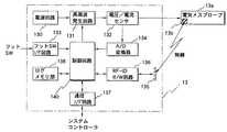
更に、カート11にはシステムコントローラ22が載置されている。このシステムコントローラ22は、上述の電気メス装置13と気腹装置14と内視鏡用カメラ装置15と光源装置16とVTR17とに、図示しない通信線を介して接続している。 Further, a
また、システムコントローラ22は、ヘッドセット型のマイク33を接続可能になっており、システムコントローラ22はマイク33から入力された音声を認識し、術者の音声により各機器を制御できるようになっている。 The
システムコントローラ22とこれらの装置との間で通信が行われている場合、システムコントローラ22は、上述の操作パネル21の液晶ディスプレイ上に、接続されている装置の設定状態や操作スイッチ等の設定画面を表示できるようになっている。さらに、システムコントローラ22は、操作パネル21の所望の操作スイッチが触れられて所定領域のタッチパネルが操作されることによって設定値の変更等の操作入力が行えるようになっている。 When communication is performed between the
リモートコントローラ30は、滅菌域にいる執刀医等が操作する第2集中操作装置であり、通信が成立している他の装置を、システムコントローラ22を介して操作することができるようになっている。 The remote controller 30 is a second centralized operation device operated by a surgeon or the like in the sterilization area, and can operate other devices that have established communication via the
このシステムコントローラ22は、図示しない患者モニタシステムに接続されており、後述するように、患者モニタシステムから取得した生体情報を解析し、この解析結果を所要の表示装置に表示させることができる。 The
また、システムコントローラ22には、通信手段である赤外線通信ポート(図示せず)が取り付けられている。この赤外線通信ポートは、表示装置19の近傍等の赤外線が照射しやすい位置に設けられ、システムコントローラ22との間がケーブルで接続されている。システムコントローラ22は、ネットワークケーブル9を介して図示しない院内サーバと院内LANにより接続されている。 The
図2に示すように、前記電気メス装置13は、制御回路140の制御に基づき、電源回路130、高周波発生回路131により電気メスプローブ13aを駆動し、患部を処置する。高周波発生回路131の出力状況(稼働状況)はA/D変換器134により稼働状況検知手段としての制御回路140にフィードバックされるようになっている。 As shown in FIG. 2, the
また、電気メスプローブ13aには、電気メスプローブ13aの種別であるプローブIDを格納しているRF-IDチップ13bが設けられている。電気メス装置13は、RF-IDアンテナ部135を用いRF-IDチップ13bとデータを交信し、RF-ID W/R回路136を介して、プローブIDの送受が可能に構成されている。 The
さらに、前記電気メス装置13の制御回路140は、フットSW40(図1参照)のフット操作信号をトリガ信号として、電気メスプローブ13aを駆動するようになっている。また、制御回路140は、フットSW40のフット操作信号をトリガ信号として、高周波発生回路131の出力電圧及び出力電流を所定のタイミング間隔(例えば50ms毎)でサンプリングして取り込み、取り込んだ出力電圧及び出力電流より出力電力及びインピーダンスを算出する。そして、制御回路140は、出力電圧、出力電流、出力電力及びインピーダンスを処置具稼働状況記録手段としてのログメモリ138に記憶するようになっている。さらにまた、制御回路140は、通信インターフェイス(以下、通信I/Fと記す)回路137を介することで、システムコントローラ22と種々のデータを送受可能に構成されている。なお、制御回路140は、RF-ID W/R回路136を介して得られたプローブIDをログメモリ138に記憶する。 Further, the
図3に示すように、前記内視鏡用カメラ装置15は、内視鏡31の撮像素子としての、例えばCCD(図示せず)を駆動するCCDドライバ160と、CCD(図示せず)からの撮像信号を前処理(相関2重サンプリング処理、A/D変換器等)を行う前処理回路161を備えている。なお、内視鏡31の撮像素子は、上記CCDに限らず、例えばC-MOSセンサにより構成してもよい。 As shown in FIG. 3, the
また、内視鏡用カメラ装置15は、前処理回路161にて撮像信号からデジタル化された映像信号を信号処理する映像信号処理回路162と、映像信号処理回路162にて信号処理された映像信号を表示装置19に出力する映像出力回路163を有している。 In addition, the
さらに、内視鏡用カメラ装置15は、映像信号処理回路162が信号処理した映像信号の最新の、例えば5数秒間にわたる、フレーム画像として記録するするフレームメモリ部164と、フレームメモリ部164が記録しているフレーム画像を、フットSW40(図1参照)のフット操作信号をトリガ信号とした、所定のタイミングにて、少なくとも、トリガ信号の発生時刻の前後の、例えば3秒間のフレーム画像を格納する画像記憶部165を備えている。 Furthermore, the
なお、内視鏡用カメラ装置15は、上記各部を制御する制御回路170を有しており、制御回路170は、通信I/F回路166を介することで、システムコントローラ22と種々のデータを送受可能に構成されている。 The
また、画像記憶部165における画像記憶のタイミングは、制御回路170の制御に行われる。詳細には、制御回路170は、(稼働状況検知手段としての制御回路140が検知した)フットSW40(図1参照)のフット操作信号をトリガ信号としてシステムコントローラ22を介して入力し、画像記憶部165へのフレームメモリ部164のフレーム画像の格納タイミングを制御する。 The timing of image storage in the
図4に示すように、システムコントローラ22は、上記の被制御装置である医療機器として例えば電気メス装置13、気腹装置14、内視鏡用カメラ装置15、光源装置16とデータを送受する通信I/F回路220と、通信I/F回路220を介してこれら被制御装置である医療機器を制御するシステム制御回路221とから構成される。 As shown in FIG. 4, the
システム制御回路221は、周辺装置制御部222、処置具出力データ分析部223、操作パネル制御部224、集中表示パネル制御部225及びネットワーク制御部226とを備えて構成される。 The system control circuit 221 includes a peripheral
前記周辺装置制御部222は、通信I/F回路220を介して、上記の被制御装置である医療機器として例えば電気メス装置13、気腹装置14、内視鏡用カメラ装置15、光源装置16とデータを送受して、各装置を制御する制御部である。 The peripheral
前記操作パネル制御部224は、前記操作パネル21とデータを送受し、該操作パネル21を制御する制御部である。 The operation
前記集中表示パネル制御部225は、前記集中表示パネル20を制御する制御部である。 The centralized display
前記ネットワーク制御部226は、ネットワークケーブル9(図1参照)を介して院内LAN接続処理を実行する制御部である。 The
また、処置具出力データ分析部223は、電気メス装置に接続される電気メスプローブ13a(図2参照)の出力データを分析する分析部である。 The treatment instrument output
図5に示すように、処置具出力データ分析部223は、前記電気メス装置13からの電気メスデータより電気メスプローブ13aのプローブIDを抽出する、処置具種別識別手段としてのプローブID抽出部250を有している。また、処置具出力データ分析部223は、前記電気メス装置13からの電気メスデータより電気メスプローブ13aの出力波形データを抽出する出力波形抽出部251を有している。 As shown in FIG. 5, the treatment instrument output
さらに、処置具出力データ分析部223は、出力波形抽出部251が抽出した電気メスプローブ13aの出力波形データを分析する稼働状況分析手段及び対処情報抽出手段としてのデータ分析部252と、画像記憶部165からの内視鏡画像を格納する内視鏡画像格納部253と、データ分析部252が分析した分析結果を集中表示パネル20に表示させる告知手段手段としての分析結果出力部255とを備えている。 Further, the treatment instrument output
内視鏡画像格納部253は、データ分析部252が分析する電気メスプローブ13aの出力波形データが出力されている際の、内視鏡画像データ(内視鏡用カメラ装置データ)を内視鏡用カメラ装置15の画像記憶部165から読み出し格納する画像データ格納部である。 The endoscopic
また、処置具出力データ分析部223の分析結果出力部255は、内視鏡用カメラ装置15の画像記憶部165が記憶し、内視鏡画像格納部253に格納されたフレーム画像とデータ分析部252が分析した分析結果と合成した合成画像とを集中表示パネル20に表示させることができるようになっている。 The analysis
処置具出力データ分析部223のデータ分析部252は、対処情報記憶手段としてのデータベース部254のモデル波形格納部254a及び対応情報格納部254bに格納されている、モデル波形及び対応情報に基づき、出力波形抽出部251が抽出した電気メスプローブ13aの出力波形データを分析する。 The
なお、モデル波形格納部254aが格納しているモデル波形及び対応情報格納部254bが格納している対応情報については、後述する。 Note that the model waveform stored in the model
次に、このように構成された本実施例の作用について、図6のフローチャート及び図7ないし図17の説明図を用いて説明する。 Next, the operation of the present embodiment configured as described above will be described with reference to the flowchart of FIG. 6 and the explanatory diagrams of FIGS.
まず、システムコントローラ22及び電気メス装置13との電源がオンされると、電気メス装置13の内部時刻をシステムコントローラ22の内部時刻に合わせる。 First, when the
そして、図6に示すように、ステップS1にて内視鏡手術システム1による手技が開始されると、まず、電気メス装置13においてRF-ID W/R回路136を介してプローブIDを検知し、得られたプローブIDをログメモリ138に記憶する(処置具識別情報検知工程)。 Then, as shown in FIG. 6, when the procedure by the
そして、ステップS2にて内視鏡手術システム1は、電気メス装置13において処置出力指示信号(フットSW40のフット操作信号)があったかどうか判断する(稼働状況検知工程)。 In step S2, the
処置出力指示信号があると、この処置出力指示信号をトリガ信号として、ステップS3にて内視鏡手術システム1は、電気メス装置13において処置出力を開始する。 If there is a treatment output instruction signal, the
続いて、内視鏡手術システム1は、前記処置出力指示信号をトリガ信号として、ステップS4にて電気メス装置13においてA/D変換器134を介して出力データのサンプリングを行うと共に、サンプリングされた出力波形データをログメモリ138に格納する(処置具稼働状況記録工程)。 Subsequently, the
この出力データは、図7に示すように、例えば50msの間隔でサンプリングされた電圧データ及び電流データからなる。 As shown in FIG. 7, the output data includes voltage data and current data sampled at intervals of 50 ms, for example.
さらに、内視鏡手術システム1は、前記処置出力指示信号をトリガ信号として、ステップS5にて内視鏡用カメラ装置15においてフレームメモリ部164に記録している、図8に示すような時間的に前後少なくとも数秒間にわたる、複数のフレーム画像500aを画像記憶部165に格納する。 Furthermore, the
そして、内視鏡手術システム1は、ステップS6にて操作パネル21からの分析指示命令を待ち、分析指示命令が無ければステップS2に戻り、分析指示命令があるとステップS7に進む。 The
なお、分析指示命令は、術者が電気メス装置13にて処置を実施している際に、所望の処置結果が得られない場合に、術者により発せられる命令である。この命令により後述するような波形分析が行われ、分析結果が集中表示パネル20に表示される。術者は分析結果を集中表示パネル20にて確認することで、電気メス装置13における現在の処置を的確に把握することができる。 The analysis instruction command is a command issued by the surgeon when a desired treatment result cannot be obtained while the surgeon is performing the treatment with the
ステップS7では、内視鏡手術システム1は、ログメモリ138に格納されているプローブID及びサンプリングされた出力波形データに基づき、波形分析を行う(稼働状況分析工程)。 In step S7, the
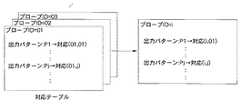
具体的は、図9に示すように、データベース部254のモデル波形格納部254a及び対応情報格納部254bに格納されている、プローブID毎のモデル波形及び対応情報に基づき、出力波形抽出部251が抽出した電気メスプローブ13aの出力波形データを分析する。例えばプローブID=i、モデル波形=出力パターンPjならば、対応情報である対応(i,j)を分析結果とする。この対応(i,j)は、図示はしないが、データベース部254に格納されている対応コメント情報とリンクしており、内視鏡手術システム1は、データベース部254より対応コメント情報を抽出する(対処情報抽出工程)。 Specifically, as shown in FIG. 9, the output
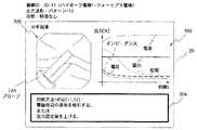
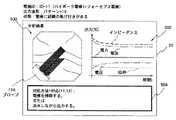
そして、内視鏡手術システム1は、ステップS8にて、図10に示すように、集中表示パネル20に、この対応コメント情報504と共に、出力波形データ502及びフレーム画像500を分析結果として表示する(稼働状況告知工程)。 Then, in step S8, the
この対応コメント情報は、サンプリングされ、処置具稼働状況記録手段としてのログメモリ138に記憶されている出力波形データを処置具の稼働状況として分析した際の、対処情報記憶手段としてのデータベース部254から抽出された対処情報である。 The corresponding comment information is sampled and is output from the
そして、内視鏡手術システム1は、上記処理をステップS9にて手技の終了を検知するまで繰り返す。 And the
図10はプローブIDが01(モノポーラフック電極あるいはヘラ電極)であって、出力波形データがモデルパターン=01の場合の、対応コメント情報504を、出力波形データ502及びフレーム画像500と共に表示した集中表示パネル20の表示例を示している。この図10の場合は、処置状態が「電気メスプローブ13aから放電が発生しており、設定値に対して電極が大きい(設定値が小さい)」状態あるいは「電極が生食/血液に沈んでいる」状態と判断し、対応コメント情報504として「設定値を上げる」あるいは「電極周辺の液体を吸引する」とのコメントを表示し、術者に対応を促す表示となっている。 FIG. 10 shows a centralized display in which the
図11はプローブIDが02(モノポーラスネア電極)であって、出力波形データがモデルパターン=01の場合の、対応コメント情報504を、出力波形データ502及びフレーム画像500と共に表示した集中表示パネル20の表示例を示している。この図11の場合は、処置状態が「放電が発生していない状態で、スネアを絞っている」状態あるいは「ポリープ痕から出血している」状態と判断し、対応コメント情報504として「設定値を上げる」あるいは「放電が確認できるまでスネアを絞らない」とのコメントを表示し、術者に対応を促す表示となっている。 FIG. 11 shows the
図12はプローブIDが03(モノポーラループ電極)であって、出力波形データがモデルパターン=02の場合の、対応コメント情報504を、出力波形データ502及びフレーム画像500と共に表示した集中表示パネル20の表示例を示している。この図12の場合は、処置状態が「放電が発生しており止血されている状態で、電極を動かすと再度出血する」状態と判断し、対応コメント情報504として「電極を動かさない」あるいは「設定値を下げる、あるいは放電の弱いモードを使用する」とのコメントを表示し、術者に対応を促す表示となっている。 FIG. 12 shows the
図13はプローブIDが01(モノポーラフック電極あるいはヘラ電極)であって、出力波形データがモデルパターン=03の場合の、対応コメント情報504を、出力波形データ502及びフレーム画像500と共に表示した集中表示パネル20の表示例を示している。この図13の場合は、処置状態が「電極を組織に押し付けて出力している」状態あるいは「電極を引いたときに、出血あるいは組織が付着した」状態と判断し、対応コメント情報504として「設定値を上げるあるいは放電の強いモードを使用する」あるいは「非接触凝固モード使用」とのコメントを表示し、術者に対応を促す表示となっている。 FIG. 13 shows a centralized display in which the
図14はプローブIDが01(モノポーラフック電極あるいはヘラ電極)であって、出力波形データがモデルパターン=04の場合の、対応コメント情報504を、出力波形データ502及びフレーム画像500と共に表示した集中表示パネル20の表示例を示している。この図14の場合は、処置状態が「放電、組織の変性が確認できない」状態と判断し、対応コメント情報504として「接触確認あるいはAコード交換」あるいは「アクセサリ交換」とのコメントを表示し、術者に対応を促す表示となっている。 FIG. 14 shows a centralized display in which the
図15はプローブIDが11(バイポーラフォーセプス電極)であって、出力波形データがモデルパターン=11の場合の、対応コメント情報504を、出力波形データ502及びフレーム画像500と共に表示した集中表示パネル20の表示例を示している。この図15の場合は、処置状態が「設定値に対して電極が大きい(設定値が小さい)」状態あるいは「電極が生食/血液に沈んでいる」状態と判断し、対応コメント情報504として「設定値を上げる」あるいは「電極周辺の液体を吸引する」とのコメントを表示し、術者に対応を促す表示となっている。 FIG. 15 shows a centralized display panel displaying
図16はプローブIDが11(バイポーラフォーセプス電極)であって、出力波形データがモデルパターン=12の場合の、対応コメント情報504を、出力波形データ502及びフレーム画像500と共に表示した集中表示パネル20の表示例を示している。この図16の場合は、処置状態が「出力に特徴がない」状態と判断し、対応コメント情報504として「設定値を上げる」あるいは「電極周辺の液体を吸引する」とのコメントを表示し、術者に対応を促す表示となっている。 FIG. 16 shows a centralized display panel displaying the
図17はプローブIDが11(バイポーラフォーセプス電極)であって、出力波形データがモデルパターン=13の場合の、対応コメント情報504を、出力波形データ502及びフレーム画像500と共に表示した集中表示パネル20の表示例を示している。この図17の場合は、処置状態が「電極に組織の焦げ付きがある」状態と判断し、対応コメント情報504として「電極を掃除する」あるいは「送水しながら出力する」とのコメントを表示し、術者に対応を促す表示となっている。 FIG. 17 shows a centralized display panel displaying the
このように、本実施例によれば、手技中の医療機器の制御状態を詳細に分析することができ、術者に対して分析結果を集中表示パネル20にて告知することで、術者は電気メス装置13における現在の処置を的確に把握することができる。 Thus, according to the present embodiment, the control state of the medical device during the procedure can be analyzed in detail, and the operator is notified by the
図18及び図19は本発明の実施例2に係わり、図18は内視鏡手術システムの構成を示す構成図、図19は図18の内視鏡手術システムの作用を説明する説明図である。 18 and 19 relate to the second embodiment of the present invention, FIG. 18 is a configuration diagram showing the configuration of the endoscopic surgery system, and FIG. 19 is an explanatory diagram for explaining the operation of the endoscopic surgery system of FIG. .
実施例2は、実施例1とほとんど同じであるので、異なる点のみ説明し、同一の構成には同じ符号をつけ説明は省略する。 Since the second embodiment is almost the same as the first embodiment, only different points will be described, and the same components are denoted by the same reference numerals and description thereof will be omitted.
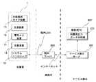
本実施例は、図18に示すように、実施例1においてシステムコントローラ22内に設けられていた処置具出力データ分析部223が、院外の解析用PC802に設けられている。 In the present embodiment, as shown in FIG. 18, the treatment instrument output
解析用PC802は、院内LAN接続された院内サーバ800及び、例えばメーカ等のサービスセンタに構築されるサービス拠点サーバ801を介してシステムコントローラ22と接続される。システムコントローラ22の内部時刻はサービス拠点サーバ801の内部時刻に合わせられる。その他の構成は実施例1と同じである。 The
このように構成された本実施例においては、術後にシステムコントローラ22を介して出力波形データ及びスコープIDを解析用PC802に出力し、解析用PC802において、モデル波形及び対応情報に基づき、電気メスプローブ13aの出力波形データを分析する。 In this embodiment configured as described above, the output waveform data and the scope ID are output to the
一般に、電気メス装置13の使用は、術者に相当程度の技術を要求するため、技術の向上が医師教育の1つの課題となっている。そこで、今日、大学病院等の教育機関での指導、あるいは個人の研鎖に際して、技術レベルを定量化した指標の構築が望まれている。 In general, the use of the
本実施例は、上記課題を解決するために、院外の解析用PC802にて電気メス装置13の使用状況を統計的処理して、前記指標を構築することを目的としている。 In order to solve the above-described problem, the present embodiment aims to construct the index by statistically processing the usage state of the
例えばTUR術では、術者の技量により、電気メス装置13の使用状況が以下の(1)〜(5)に示すようになる(図19参照)。 For example, in the TUR operation, the usage status of the
(1)切開回数/総出力回数(=切開時間/総出力時間)
熟練者は必要最小限しか止血=凝固しない。この結果、経験が少ないと、必要以上に止血=凝固を行う傾向がある。したがって、術者の技量レベル大と術者の技量レベル小とで、切開回数/総出力回数を比較すると、切開回数/総出力回数(技量レベル大)<切開回数/総出力回数(技量レベル小)となる。(1) Number of incisions / total number of outputs (= incision time / total output time)
The skilled person only stops hemostasis = coagulation. As a result, if there is little experience, there is a tendency to stop hemostasis = coagulation more than necessary. Therefore, when the number of incisions / total number of outputs is compared between the high skill level of the operator and the low skill level of the operator, the number of incisions / total output number (high skill level) <the number of incisions / total output number (low skill level) )
(2)平均切開時間
経験が少ないと、穿孔等を恐れ、出力を短時間で止める傾向がある。したがって、術者の技量レベル大と術者の技量レベル小とで、平均切開時間を比較すると、平均切開時間(技量レベル大)>平均切開時間(技量レベル小)となる。(2) Average incision time If there is little experience, there is a tendency to stop the output in a short time due to fear of perforation. Therefore, when the average incision time is compared between the high skill level of the operator and the low skill level of the operator, the average incision time (high skill level)> average incision time (low skill level).
(3)平均凝固時間
経験が少ないと、出血点がわからない/効果的な止血方法を知らない等の理由で、止血できるまで長時間出力し、広範囲を凝固する傾向がある。したがって、術者の技量レベル大と術者の技量レベル小とで、平均凝固時間を比較すると、平均凝固時間(技量レベル大)<平均凝固時間(技量レベル小)となる。(3) Average coagulation time If there is little experience, there is a tendency that the bleeding point is output for a long time until hemostasis can be stopped because the bleeding point is not known / the effective hemostasis method is not known. Therefore, when the average coagulation time is compared between the high skill level of the operator and the low skill level of the operator, the average coagulation time (high skill level) <average coagulation time (low skill level).
(4)切開時間/手術時間
経験が少ないと、出血前に処置を躊躇し、時間を浪費する傾向がある。したがって、術者の技量レベル大と術者の技量レベル小とで、切開時間/手術時間を比較すると、切開時間/手術時間(技量レベル大)<切開時間/手術時間(技量レベル小)となる。(4) Incision time / Surgery time If there is little experience, there is a tendency to hesitate treatment before bleeding and waste time. Therefore, when the incision time / operation time is compared between the high skill level of the operator and the low skill level of the operator, the incision time / operation time (high skill level) <the incision time / operative time (low skill level). .
(5)切除量/切開時間
経験が少ないと、穿孔等を恐れ、組織に深く切り込むことをしない傾向がある。したがって、術者の技量レベル大と術者の技量レベル小とで、切除量/切開時間を比較すると、切除量/切開時間(技量レベル大)>切除量/切開時間(技量レベル小)となる。(5) Amount of excision / incision time If there is little experience, there is a tendency not to cut deeply into the tissue because of fear of perforation. Therefore, when the amount of resection / incision time is compared between the high skill level of the operator and the low skill level of the operator, the resection amount / incision time (high skill level)> resection amount / incision time (low skill level). .
本実施例では、解析用PC802が、上記指標(1)〜(5)を算出し、症例毎に呼び出し可能な状態で保存する。また、解析用PC802は、術者と症例種別毎に、例えば3ヶ月程度の期間の指標の平均値を計算し、呼び出し可能な状態で保存する。 In the present embodiment, the
本実施例では、術者がサービス拠点サーバ801にアクセスし、解析用PC802にてアクセスが許可されている術者の指標の一覧が閲覧できる。例えば指導的な立場の術者は、指導すべき医師全員の指標データを確認することができ、その指標データを指導方針の参考とすることができる。 In this embodiment, the surgeon accesses the
また、 TUR術のように、高出力を使用する症例では、術者は、自身の記憶による出力時間の印象と装置の電力設定から投与エネルギを推測していたが、本実施例では、投与エネルギを定量的に把握することが可能である。以下、詳細に説明する。 In cases where high power is used, such as TUR surgery, the surgeon has estimated the dose energy from the impression of the output time based on his own memory and the power setting of the device. Can be grasped quantitatively. Details will be described below.
電力量は、出力電力と時間の積で求められる。すなわち、(装置で測定した出力電力)×(測定間隔)を一症例分測定した積算値が、投与エネルギ総量である。 The amount of electric power is obtained by the product of output power and time. That is, the integrated value obtained by measuring (output power measured by the apparatus) × (measurement interval) for one case is the total dose energy.
そこで、解析用PC802は、(装置で測定した出力電力)×(測定間隔=50ms)を一症例分積算し、呼び出し可能な状態で保存する。したがって、術者は解析用PC802にアクセスすることで、容易に投与エネルギを定量的に把握することができる。 Therefore, the
図20ないし図22は本発明の実施例3に係わり、図20は内視鏡手術システムの構成を示す構成図、図21は図20の超音波プローブの先端の構成を示す図、図22は図20の内視鏡手術システムの変形例の構成を示す構成図である。 20 to 22 relate to the third embodiment of the present invention, FIG. 20 is a configuration diagram showing the configuration of the endoscopic surgery system, FIG. 21 is a diagram showing the configuration of the tip of the ultrasonic probe of FIG. 20, and FIG. It is a block diagram which shows the structure of the modification of the endoscopic surgery system of FIG.
実施例3は、実施例1とほとんど同じであるので、異なる点のみ説明し、同一の構成には同じ符号をつけ説明は省略する。 Since the third embodiment is almost the same as the first embodiment, only different points will be described.
本実施例は、図20に示すように、電気メス装置13の代わりに、超音波処置装置(超音波切開凝固装置)1300を用いて内視鏡手術システム1を構成している。 In this embodiment, as shown in FIG. 20, an
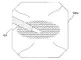
超音波処置装置(超音波切開凝固装置)1300の超音波プローブ1302は、先端に超音波振動子1303を備えて構成されている。その他の構成は実施例1と同じである。 An
超音波プローブ1302は、クリップ等の金属部材を挟んだ状態で出力すると、把持した部分にクラックが入り、その後の使用により、プローブ先端が折れ、さらには先端が脱落する恐れがある。 When the
超音波プローブ1302は、定電流駆動されるために、血管や腸膜等の組織を挟んだ状態に比べ、クリップ等の金属部材を挟んだ状態での超音波出力は大きくなる、一方、靭帯等の硬い組織を挟んだ状態でも、血管や腸膜等の組織を挟んだ状態に比べ、超音波出力は大きくなるが、この状態では把持した部分にクラックが入ることはない。 Since the
そこで、本実施例では、超音波出力が所定値よりも大きい場合には、集中表示パネル20に内視鏡画像を表示することで、内視鏡画像によりクリップ等の金属部材を挟んだ状態かどうか判断することを可能としている。 Therefore, in this embodiment, when the ultrasonic output is larger than a predetermined value, an endoscopic image is displayed on the
また、超音波プローブ1302の先端に設けられる把持部においては、上述したように、超音波振動している金属部位1310に直接、クリップ等の金属部材を押し当てると、クラックが入ったり、耳障りな高い音が発生する。そこで、図21に示すように、金属部位1310の間の把持部に樹脂1311が設けられることがあるが、このような樹脂1311は、出力を行う度に摩耗するので、使用限界は、例えば20回程度であり、その後は交換する必要がある。 In addition, in the gripping portion provided at the tip of the
本実施例では、超音波プローブ1302の出力情報(出力設定値、先端部シリアル番号)をログメモリ部138(図20参照)に格納し、処置具出力データ分析部223は、この出力情報を積算し、積算した出力情報に基づき、想定使用可能時間の例えば80%となった時点で、集中表示パネル20に、超音波プローブ1302の先端の交換を告知する。
なお、本実施例において、実施例2と同様に、図22に示すように、システムコントローラ22内に設けられていた処置具出力データ分析部223を、院外の解析用PC802に設けて構成してもよい。In this embodiment, the output information (output set value, tip serial number) of the
In this embodiment, as in the second embodiment, as shown in FIG. 22, the treatment instrument output
本発明は、上述した実施例に限定されるものではなく、本発明の要旨を変えない範囲において、種々の変更、改変等が可能である。 The present invention is not limited to the above-described embodiments, and various changes and modifications can be made without departing from the scope of the present invention.
1…内視鏡手術システム
13…電気メス装置
15…内視鏡用カメラ装置
20…集中表示パネル
21…操作パネル
22…システムコントローラ
223…処置具出力データ分析部
250…プローブID抽出部
251…出力波形抽出部
252…データ分析部
253…内視鏡画像格納部
254…データベース部
254a…モデル波形格納部
254b…対応情報格納部
255…分析結果出力部DESCRIPTION OF
Claims (7)
Translated fromJapanese前記患部に対する処置に使用される前記処置具の種別を識別する処置具種別識別手段と、
前記医療処置装置からの電気的エネルギーの出力状況に関する複数のモデルパターンが前記処置具の種別毎に予め記憶されたモデルパターン記憶手段と、
前記複数のモデルパターンに対応した対応情報が前記処置具の種別毎に予め記憶された対応情報記憶手段と、
前記医療処置装置からの電気的エネルギーの出力状況を検知する出力状況検知手段と、
前記出力状況検知手段が検知した、前記医療処置装置からの電気的エネルギーの出力状況を記録する出力状況記録手段と、
前記処置具種別識別手段の識別結果と、前記出力状況記録手段に記録された電気的エネルギーの出力状況と、に基づいて前記モデルパターン記憶手段に記憶された前記複数のモデルパターンから一のモデルパターンを選択するとともに、該一のモデルパターンに対応する前記対応情報を前記対応情報記憶手段から抽出する分析手段と、
を備えたことを特徴とする手術システム。A treatment instrument that is supplied with electrical energy from a medical treatment device and treats the affected area with the supplied electrical energy ;
A treatment tool type identifying means for identifying the type of the treatment tool used for treatment of the affected area;
A plurality of model patterns related to the output state of electrical energy from the medical treatment device, model pattern storage means stored in advance for each type of the treatment tool;
Correspondence information storage meansin which correspondence information corresponding to the plurality of model patterns is stored in advance for each type of the treatment tool ;
Output status detection means for detecting theoutput statusof electrical energy from the medical treatment device ;
Theoutput status detection unit detects theoutput state recording unitthat records theoutput status of the electrical energy from the medical treatment device,
One model pattern from the plurality of model patterns stored in the model pattern storage unit based on the identification result of the treatment instrument type identification unit and the output state of electrical energy recorded in the output state recording unit Analyzing means for extracting the correspondence information corresponding to the one model pattern from the correspondence information storage means;
A surgical system characterized by comprising:
前記出力状況記録手段には、前記出力状況検知手段により検知された電気的エネルギーの出力状況が出力波形データとして記録される
ことを特徴とする請求項1に記載の手術システム。In the model pattern storage means, a model waveform when electrical energy is output from the medical treatment device is stored in advance for each type of the treatment tool,
2. The surgical operation system according to claim 1,wherein the output status recording means records the output status of electrical energy detected by the output status detection means as output waveform data .
ことを特徴とする請求項1に記載の手術システム。Theoutput status detecting means, theoutput state of the electrical energy from the medical treatment device, is sampled at sampling intervals of a predetermined timing, accordingto claim 1, characterized in that to detect a plurality of sampling information Surgery system.
ことを特徴とする請求項1または2に記載の手術システム。The surgical operation system according toclaim 1 or 2 ,further comprising notification screen generation means for generating a notification screen including the correspondence information and the output waveform data used for processing in the analysis means. .
ことを特徴とする請求項1乃至4のいずれか1つに記載の手術システム。5. The analysis apparatus according toclaim 1, wherein the analyzing unit is provided in an external device connected to the output status detecting unit and the output status recording unit via a communication line. The described surgical system.
ことを特徴とする請求項1乃至5のいずれか1つに記載の手術システム。The analysis means calculates an index indicating a technical level for each user who uses the treatment instrument by performing statistical processing based on an output situation of electrical energy recorded in the output situation recording means. The surgical operation system according to anyone of claims 1 to 5 , characterized in that:
前記医療処置装置からの電気的エネルギーの出力状況を検知する出力状況検知工程と、
前記出力状況検知工程にて検知した、前記医療処置装置からの電気的エネルギーの出力状況を記録する出力状況記録工程と、
前記処置具識別情報検出工程にて検出された前記識別情報と、前記出力状況記録工程にて記録した電気的エネルギーの出力状況と、に基づき、前記医療処置装置からの電気的エネルギーの出力状況に関する複数のモデルパターンが前記処置具の種別毎に予め記憶されたモデルパターン記憶手段から一のモデルパターンを選択するモデルパターン選択工程と、
前記複数のモデルパターンに対応した対応情報が前記処置具の種別毎に予め記憶された対応情報記憶手段から、前記モデルパターン選択工程において選択された前記一のモデルパターンに対応する前記対応情報を抽出する対応情報抽出工程と、
前記出力状況記録工程にて記録された電気的エネルギーの出力状況を分析することにより得られる分析結果を、所定の告知条件に基づき告知手段に出力する分析結果告知工程と、
を備えたことを特徴とする手術システムのシステム稼働情報告知方法。A treatment instrument identification information detection step of detecting identification informationfor identifying the type of treatment instrumentwhich is supplied with electrical energy from the medical treatment apparatus and treats the affected area with the supplied electrical energy ;
Anoutput status detection step of detecting anoutput statusof electrical energy from the medical treatment device ;
Detected by saidoutput status detecting step, anoutput status recording stepthat records theoutput status of the electrical energy from the medical treatment device,
Based on the identification information detected in the treatment instrument identification information detection stepand the output status of electrical energy recorded in the output status recording step, the output statusof electrical energy from the medical treatment device A model pattern selection step of selecting one model pattern from a model pattern storage means in which a plurality of model patterns are stored in advance for each type of the treatment tool;
From the correspondence information storage means corresponding information corresponding to the plurality of model patterns stored in advance for each type of the treatment instrument, extracts thecorrespondinginformation corresponding to the one model patterns selected in the model pattern selection step Thecorresponding information extraction process,
Ananalysis result notification step of outputting ananalysis resultobtained by analyzing the output status of the electrical energy recorded in the output status recording step to a notification means based on a predetermined notification condition;
A system operation information notification method for a surgical system characterized by comprising:
Priority Applications (2)
| Application Number | Priority Date | Filing Date | Title |
|---|---|---|---|
| JP2006162918AJP4504332B2 (en) | 2006-06-12 | 2006-06-12 | Surgical system and system operation information notification method |
| US11/811,798US7667592B2 (en) | 2006-06-12 | 2007-06-12 | Operation system and method of notifying system operation information of same |
Applications Claiming Priority (1)
| Application Number | Priority Date | Filing Date | Title |
|---|---|---|---|
| JP2006162918AJP4504332B2 (en) | 2006-06-12 | 2006-06-12 | Surgical system and system operation information notification method |
Publications (2)
| Publication Number | Publication Date |
|---|---|
| JP2007330347A JP2007330347A (en) | 2007-12-27 |
| JP4504332B2true JP4504332B2 (en) | 2010-07-14 |
Family
ID=38930390
Family Applications (1)
| Application Number | Title | Priority Date | Filing Date |
|---|---|---|---|
| JP2006162918AExpired - Fee RelatedJP4504332B2 (en) | 2006-06-12 | 2006-06-12 | Surgical system and system operation information notification method |
Country Status (2)
| Country | Link |
|---|---|
| US (1) | US7667592B2 (en) |
| JP (1) | JP4504332B2 (en) |
Cited By (1)
| Publication number | Priority date | Publication date | Assignee | Title |
|---|---|---|---|---|
| US7910836B2 (en) | 1999-08-12 | 2011-03-22 | Ibiden Co. Ltd. | Multilayered printed circuit board, solder resist composition, and semiconductor device |
Families Citing this family (213)
| Publication number | Priority date | Publication date | Assignee | Title |
|---|---|---|---|---|
| US11229472B2 (en) | 2001-06-12 | 2022-01-25 | Cilag Gmbh International | Modular battery powered handheld surgical instrument with multiple magnetic position sensors |
| US9089360B2 (en) | 2008-08-06 | 2015-07-28 | Ethicon Endo-Surgery, Inc. | Devices and techniques for cutting and coagulating tissue |
| US8663220B2 (en) | 2009-07-15 | 2014-03-04 | Ethicon Endo-Surgery, Inc. | Ultrasonic surgical instruments |
| US10441345B2 (en) | 2009-10-09 | 2019-10-15 | Ethicon Llc | Surgical generator for ultrasonic and electrosurgical devices |
| US11090104B2 (en) | 2009-10-09 | 2021-08-17 | Cilag Gmbh International | Surgical generator for ultrasonic and electrosurgical devices |
| US8469981B2 (en) | 2010-02-11 | 2013-06-25 | Ethicon Endo-Surgery, Inc. | Rotatable cutting implement arrangements for ultrasonic surgical instruments |
| US8795327B2 (en) | 2010-07-22 | 2014-08-05 | Ethicon Endo-Surgery, Inc. | Electrosurgical instrument with separate closure and cutting members |
| US9192431B2 (en) | 2010-07-23 | 2015-11-24 | Ethicon Endo-Surgery, Inc. | Electrosurgical cutting and sealing instrument |
| EP2589329B1 (en)* | 2010-10-14 | 2017-02-22 | Olympus Corporation | Endoscope and endoscopic system |
| JP2012203572A (en)* | 2011-03-24 | 2012-10-22 | Morita Mfg Co Ltd | Medical treatment device |
| US9259265B2 (en) | 2011-07-22 | 2016-02-16 | Ethicon Endo-Surgery, Llc | Surgical instruments for tensioning tissue |
| KR101175065B1 (en)* | 2011-11-04 | 2012-10-12 | 주식회사 아폴로엠 | Method for bleeding scanning during operation using image processing apparatus for surgery |
| WO2013119545A1 (en) | 2012-02-10 | 2013-08-15 | Ethicon-Endo Surgery, Inc. | Robotically controlled surgical instrument |
| US9486271B2 (en) | 2012-03-05 | 2016-11-08 | Covidien Lp | Method and apparatus for identification using capacitive elements |
| US9439668B2 (en) | 2012-04-09 | 2016-09-13 | Ethicon Endo-Surgery, Llc | Switch arrangements for ultrasonic surgical instruments |
| US11871901B2 (en) | 2012-05-20 | 2024-01-16 | Cilag Gmbh International | Method for situational awareness for surgical network or surgical network connected device capable of adjusting function based on a sensed situation or usage |
| US20140005705A1 (en) | 2012-06-29 | 2014-01-02 | Ethicon Endo-Surgery, Inc. | Surgical instruments with articulating shafts |
| US20140005702A1 (en) | 2012-06-29 | 2014-01-02 | Ethicon Endo-Surgery, Inc. | Ultrasonic surgical instruments with distally positioned transducers |
| US9351754B2 (en) | 2012-06-29 | 2016-05-31 | Ethicon Endo-Surgery, Llc | Ultrasonic surgical instruments with distally positioned jaw assemblies |
| US9198714B2 (en) | 2012-06-29 | 2015-12-01 | Ethicon Endo-Surgery, Inc. | Haptic feedback devices for surgical robot |
| US9393037B2 (en) | 2012-06-29 | 2016-07-19 | Ethicon Endo-Surgery, Llc | Surgical instruments with articulating shafts |
| US9326788B2 (en) | 2012-06-29 | 2016-05-03 | Ethicon Endo-Surgery, Llc | Lockout mechanism for use with robotic electrosurgical device |
| US9226767B2 (en) | 2012-06-29 | 2016-01-05 | Ethicon Endo-Surgery, Inc. | Closed feedback control for electrosurgical device |
| US9408622B2 (en) | 2012-06-29 | 2016-08-09 | Ethicon Endo-Surgery, Llc | Surgical instruments with articulating shafts |
| EP2900158B1 (en) | 2012-09-28 | 2020-04-15 | Ethicon LLC | Multi-function bi-polar forceps |
| US9095367B2 (en) | 2012-10-22 | 2015-08-04 | Ethicon Endo-Surgery, Inc. | Flexible harmonic waveguides/blades for surgical instruments |
| US20140135804A1 (en) | 2012-11-15 | 2014-05-15 | Ethicon Endo-Surgery, Inc. | Ultrasonic and electrosurgical devices |
| US9814514B2 (en) | 2013-09-13 | 2017-11-14 | Ethicon Llc | Electrosurgical (RF) medical instruments for cutting and coagulating tissue |
| US9265926B2 (en) | 2013-11-08 | 2016-02-23 | Ethicon Endo-Surgery, Llc | Electrosurgical devices |
| GB2521228A (en) | 2013-12-16 | 2015-06-17 | Ethicon Endo Surgery Inc | Medical device |
| US9795436B2 (en) | 2014-01-07 | 2017-10-24 | Ethicon Llc | Harvesting energy from a surgical generator |
| US9554854B2 (en) | 2014-03-18 | 2017-01-31 | Ethicon Endo-Surgery, Llc | Detecting short circuits in electrosurgical medical devices |
| US10130382B2 (en) | 2014-03-27 | 2018-11-20 | Medtronic Xomed, Inc. | Powered surgical handpiece having a surgical tool with an RFID tag |
| US10092310B2 (en) | 2014-03-27 | 2018-10-09 | Ethicon Llc | Electrosurgical devices |
| US10463421B2 (en) | 2014-03-27 | 2019-11-05 | Ethicon Llc | Two stage trigger, clamp and cut bipolar vessel sealer |
| US9737355B2 (en) | 2014-03-31 | 2017-08-22 | Ethicon Llc | Controlling impedance rise in electrosurgical medical devices |
| US9913680B2 (en) | 2014-04-15 | 2018-03-13 | Ethicon Llc | Software algorithms for electrosurgical instruments |
| US20150317899A1 (en) | 2014-05-01 | 2015-11-05 | Covidien Lp | System and method for using rfid tags to determine sterilization of devices |
| US10285724B2 (en) | 2014-07-31 | 2019-05-14 | Ethicon Llc | Actuation mechanisms and load adjustment assemblies for surgical instruments |
| US11504192B2 (en) | 2014-10-30 | 2022-11-22 | Cilag Gmbh International | Method of hub communication with surgical instrument systems |
| JP6305907B2 (en)* | 2014-11-19 | 2018-04-04 | オリンパス株式会社 | Endoscope system |
| US10639092B2 (en) | 2014-12-08 | 2020-05-05 | Ethicon Llc | Electrode configurations for surgical instruments |
| US10245095B2 (en) | 2015-02-06 | 2019-04-02 | Ethicon Llc | Electrosurgical instrument with rotation and articulation mechanisms |
| US10342602B2 (en) | 2015-03-17 | 2019-07-09 | Ethicon Llc | Managing tissue treatment |
| US10595929B2 (en) | 2015-03-24 | 2020-03-24 | Ethicon Llc | Surgical instruments with firing system overload protection mechanisms |
| US11051873B2 (en) | 2015-06-30 | 2021-07-06 | Cilag Gmbh International | Surgical system with user adaptable techniques employing multiple energy modalities based on tissue parameters |
| US11129669B2 (en) | 2015-06-30 | 2021-09-28 | Cilag Gmbh International | Surgical system with user adaptable techniques based on tissue type |
| US11141213B2 (en) | 2015-06-30 | 2021-10-12 | Cilag Gmbh International | Surgical instrument with user adaptable techniques |
| US10898256B2 (en) | 2015-06-30 | 2021-01-26 | Ethicon Llc | Surgical system with user adaptable techniques based on tissue impedance |
| US10034704B2 (en) | 2015-06-30 | 2018-07-31 | Ethicon Llc | Surgical instrument with user adaptable algorithms |
| US10194973B2 (en) | 2015-09-30 | 2019-02-05 | Ethicon Llc | Generator for digitally generating electrical signal waveforms for electrosurgical and ultrasonic surgical instruments |
| US10595930B2 (en) | 2015-10-16 | 2020-03-24 | Ethicon Llc | Electrode wiping surgical device |
| US10575892B2 (en) | 2015-12-31 | 2020-03-03 | Ethicon Llc | Adapter for electrical surgical instruments |
| US11051840B2 (en) | 2016-01-15 | 2021-07-06 | Ethicon Llc | Modular battery powered handheld surgical instrument with reusable asymmetric handle housing |
| US11129670B2 (en) | 2016-01-15 | 2021-09-28 | Cilag Gmbh International | Modular battery powered handheld surgical instrument with selective application of energy based on button displacement, intensity, or local tissue characterization |
| US10716615B2 (en) | 2016-01-15 | 2020-07-21 | Ethicon Llc | Modular battery powered handheld surgical instrument with curved end effectors having asymmetric engagement between jaw and blade |
| US11229471B2 (en) | 2016-01-15 | 2022-01-25 | Cilag Gmbh International | Modular battery powered handheld surgical instrument with selective application of energy based on tissue characterization |
| US12193698B2 (en) | 2016-01-15 | 2025-01-14 | Cilag Gmbh International | Method for self-diagnosing operation of a control switch in a surgical instrument system |
| US10555769B2 (en) | 2016-02-22 | 2020-02-11 | Ethicon Llc | Flexible circuits for electrosurgical instrument |
| US10485607B2 (en) | 2016-04-29 | 2019-11-26 | Ethicon Llc | Jaw structure with distal closure for electrosurgical instruments |
| US10702329B2 (en) | 2016-04-29 | 2020-07-07 | Ethicon Llc | Jaw structure with distal post for electrosurgical instruments |
| US10646269B2 (en) | 2016-04-29 | 2020-05-12 | Ethicon Llc | Non-linear jaw gap for electrosurgical instruments |
| US10456193B2 (en) | 2016-05-03 | 2019-10-29 | Ethicon Llc | Medical device with a bilateral jaw configuration for nerve stimulation |
| US20180014872A1 (en)* | 2016-07-15 | 2018-01-18 | Ethicon Endo-Surgery, Llc | Paired device and generator codes |
| US10376305B2 (en) | 2016-08-05 | 2019-08-13 | Ethicon Llc | Methods and systems for advanced harmonic energy |
| US11266430B2 (en) | 2016-11-29 | 2022-03-08 | Cilag Gmbh International | End effector control and calibration |
| US11229436B2 (en) | 2017-10-30 | 2022-01-25 | Cilag Gmbh International | Surgical system comprising a surgical tool and a surgical hub |
| US11317919B2 (en) | 2017-10-30 | 2022-05-03 | Cilag Gmbh International | Clip applier comprising a clip crimping system |
| US11925373B2 (en) | 2017-10-30 | 2024-03-12 | Cilag Gmbh International | Surgical suturing instrument comprising a non-circular needle |
| US11911045B2 (en) | 2017-10-30 | 2024-02-27 | Cllag GmbH International | Method for operating a powered articulating multi-clip applier |
| US11510741B2 (en) | 2017-10-30 | 2022-11-29 | Cilag Gmbh International | Method for producing a surgical instrument comprising a smart electrical system |
| US11291510B2 (en) | 2017-10-30 | 2022-04-05 | Cilag Gmbh International | Method of hub communication with surgical instrument systems |
| US11026687B2 (en) | 2017-10-30 | 2021-06-08 | Cilag Gmbh International | Clip applier comprising clip advancing systems |
| US11311342B2 (en) | 2017-10-30 | 2022-04-26 | Cilag Gmbh International | Method for communicating with surgical instrument systems |
| US11801098B2 (en) | 2017-10-30 | 2023-10-31 | Cilag Gmbh International | Method of hub communication with surgical instrument systems |
| US11564756B2 (en) | 2017-10-30 | 2023-01-31 | Cilag Gmbh International | Method of hub communication with surgical instrument systems |
| US11896322B2 (en) | 2017-12-28 | 2024-02-13 | Cilag Gmbh International | Sensing the patient position and contact utilizing the mono-polar return pad electrode to provide situational awareness to the hub |
| US11389164B2 (en) | 2017-12-28 | 2022-07-19 | Cilag Gmbh International | Method of using reinforced flexible circuits with multiple sensors to optimize performance of radio frequency devices |
| US12127729B2 (en) | 2017-12-28 | 2024-10-29 | Cilag Gmbh International | Method for smoke evacuation for surgical hub |
| US11304763B2 (en) | 2017-12-28 | 2022-04-19 | Cilag Gmbh International | Image capturing of the areas outside the abdomen to improve placement and control of a surgical device in use |
| US11464559B2 (en) | 2017-12-28 | 2022-10-11 | Cilag Gmbh International | Estimating state of ultrasonic end effector and control system therefor |
| US20190206569A1 (en) | 2017-12-28 | 2019-07-04 | Ethicon Llc | Method of cloud based data analytics for use with the hub |
| US11903601B2 (en) | 2017-12-28 | 2024-02-20 | Cilag Gmbh International | Surgical instrument comprising a plurality of drive systems |
| US11786251B2 (en) | 2017-12-28 | 2023-10-17 | Cilag Gmbh International | Method for adaptive control schemes for surgical network control and interaction |
| US11529187B2 (en) | 2017-12-28 | 2022-12-20 | Cilag Gmbh International | Surgical evacuation sensor arrangements |
| US11602393B2 (en) | 2017-12-28 | 2023-03-14 | Cilag Gmbh International | Surgical evacuation sensing and generator control |
| US11786245B2 (en) | 2017-12-28 | 2023-10-17 | Cilag Gmbh International | Surgical systems with prioritized data transmission capabilities |
| US11832899B2 (en) | 2017-12-28 | 2023-12-05 | Cilag Gmbh International | Surgical systems with autonomously adjustable control programs |
| US11291495B2 (en) | 2017-12-28 | 2022-04-05 | Cilag Gmbh International | Interruption of energy due to inadvertent capacitive coupling |
| US11540855B2 (en) | 2017-12-28 | 2023-01-03 | Cilag Gmbh International | Controlling activation of an ultrasonic surgical instrument according to the presence of tissue |
| US20190201142A1 (en) | 2017-12-28 | 2019-07-04 | Ethicon Llc | Automatic tool adjustments for robot-assisted surgical platforms |
| US12396806B2 (en) | 2017-12-28 | 2025-08-26 | Cilag Gmbh International | Adjustment of a surgical device function based on situational awareness |
| US11571234B2 (en) | 2017-12-28 | 2023-02-07 | Cilag Gmbh International | Temperature control of ultrasonic end effector and control system therefor |
| US11284936B2 (en) | 2017-12-28 | 2022-03-29 | Cilag Gmbh International | Surgical instrument having a flexible electrode |
| US11832840B2 (en) | 2017-12-28 | 2023-12-05 | Cilag Gmbh International | Surgical instrument having a flexible circuit |
| US11376002B2 (en) | 2017-12-28 | 2022-07-05 | Cilag Gmbh International | Surgical instrument cartridge sensor assemblies |
| US11253315B2 (en) | 2017-12-28 | 2022-02-22 | Cilag Gmbh International | Increasing radio frequency to create pad-less monopolar loop |
| US11659023B2 (en) | 2017-12-28 | 2023-05-23 | Cilag Gmbh International | Method of hub communication |
| US10892995B2 (en) | 2017-12-28 | 2021-01-12 | Ethicon Llc | Surgical network determination of prioritization of communication, interaction, or processing based on system or device needs |
| US11076921B2 (en) | 2017-12-28 | 2021-08-03 | Cilag Gmbh International | Adaptive control program updates for surgical hubs |
| US11666331B2 (en) | 2017-12-28 | 2023-06-06 | Cilag Gmbh International | Systems for detecting proximity of surgical end effector to cancerous tissue |
| US11160605B2 (en) | 2017-12-28 | 2021-11-02 | Cilag Gmbh International | Surgical evacuation sensing and motor control |
| US12376855B2 (en) | 2017-12-28 | 2025-08-05 | Cilag Gmbh International | Safety systems for smart powered surgical stapling |
| US11202570B2 (en) | 2017-12-28 | 2021-12-21 | Cilag Gmbh International | Communication hub and storage device for storing parameters and status of a surgical device to be shared with cloud based analytics systems |
| US11304745B2 (en) | 2017-12-28 | 2022-04-19 | Cilag Gmbh International | Surgical evacuation sensing and display |
| US11969216B2 (en) | 2017-12-28 | 2024-04-30 | Cilag Gmbh International | Surgical network recommendations from real time analysis of procedure variables against a baseline highlighting differences from the optimal solution |
| US11132462B2 (en) | 2017-12-28 | 2021-09-28 | Cilag Gmbh International | Data stripping method to interrogate patient records and create anonymized record |
| US12062442B2 (en) | 2017-12-28 | 2024-08-13 | Cilag Gmbh International | Method for operating surgical instrument systems |
| US11234756B2 (en) | 2017-12-28 | 2022-02-01 | Cilag Gmbh International | Powered surgical tool with predefined adjustable control algorithm for controlling end effector parameter |
| US11304699B2 (en) | 2017-12-28 | 2022-04-19 | Cilag Gmbh International | Method for adaptive control schemes for surgical network control and interaction |
| US11464535B2 (en) | 2017-12-28 | 2022-10-11 | Cilag Gmbh International | Detection of end effector emersion in liquid |
| US11419630B2 (en) | 2017-12-28 | 2022-08-23 | Cilag Gmbh International | Surgical system distributed processing |
| US11266468B2 (en) | 2017-12-28 | 2022-03-08 | Cilag Gmbh International | Cooperative utilization of data derived from secondary sources by intelligent surgical hubs |
| US11324557B2 (en) | 2017-12-28 | 2022-05-10 | Cilag Gmbh International | Surgical instrument with a sensing array |
| US12096916B2 (en) | 2017-12-28 | 2024-09-24 | Cilag Gmbh International | Method of sensing particulate from smoke evacuated from a patient, adjusting the pump speed based on the sensed information, and communicating the functional parameters of the system to the hub |
| WO2019133144A1 (en) | 2017-12-28 | 2019-07-04 | Ethicon Llc | Detection and escalation of security responses of surgical instruments to increasing severity threats |
| US11424027B2 (en) | 2017-12-28 | 2022-08-23 | Cilag Gmbh International | Method for operating surgical instrument systems |
| US11937769B2 (en) | 2017-12-28 | 2024-03-26 | Cilag Gmbh International | Method of hub communication, processing, storage and display |
| US11696760B2 (en) | 2017-12-28 | 2023-07-11 | Cilag Gmbh International | Safety systems for smart powered surgical stapling |
| US11179175B2 (en) | 2017-12-28 | 2021-11-23 | Cilag Gmbh International | Controlling an ultrasonic surgical instrument according to tissue location |
| US11364075B2 (en) | 2017-12-28 | 2022-06-21 | Cilag Gmbh International | Radio frequency energy device for delivering combined electrical signals |
| US11166772B2 (en) | 2017-12-28 | 2021-11-09 | Cilag Gmbh International | Surgical hub coordination of control and communication of operating room devices |
| US20190201039A1 (en) | 2017-12-28 | 2019-07-04 | Ethicon Llc | Situational awareness of electrosurgical systems |
| US11317937B2 (en) | 2018-03-08 | 2022-05-03 | Cilag Gmbh International | Determining the state of an ultrasonic end effector |
| US11857152B2 (en) | 2017-12-28 | 2024-01-02 | Cilag Gmbh International | Surgical hub spatial awareness to determine devices in operating theater |
| US11998193B2 (en) | 2017-12-28 | 2024-06-04 | Cilag Gmbh International | Method for usage of the shroud as an aspect of sensing or controlling a powered surgical device, and a control algorithm to adjust its default operation |
| US11818052B2 (en) | 2017-12-28 | 2023-11-14 | Cilag Gmbh International | Surgical network determination of prioritization of communication, interaction, or processing based on system or device needs |
| US11273001B2 (en) | 2017-12-28 | 2022-03-15 | Cilag Gmbh International | Surgical hub and modular device response adjustment based on situational awareness |
| US11559307B2 (en) | 2017-12-28 | 2023-01-24 | Cilag Gmbh International | Method of robotic hub communication, detection, and control |
| US20190201090A1 (en) | 2017-12-28 | 2019-07-04 | Ethicon Llc | Capacitive coupled return path pad with separable array elements |
| US11419667B2 (en) | 2017-12-28 | 2022-08-23 | Cilag Gmbh International | Ultrasonic energy device which varies pressure applied by clamp arm to provide threshold control pressure at a cut progression location |
| US11410259B2 (en) | 2017-12-28 | 2022-08-09 | Cilag Gmbh International | Adaptive control program updates for surgical devices |
| US11179208B2 (en) | 2017-12-28 | 2021-11-23 | Cilag Gmbh International | Cloud-based medical analytics for security and authentication trends and reactive measures |
| US11633237B2 (en) | 2017-12-28 | 2023-04-25 | Cilag Gmbh International | Usage and technique analysis of surgeon / staff performance against a baseline to optimize device utilization and performance for both current and future procedures |
| US11576677B2 (en) | 2017-12-28 | 2023-02-14 | Cilag Gmbh International | Method of hub communication, processing, display, and cloud analytics |
| US11096693B2 (en) | 2017-12-28 | 2021-08-24 | Cilag Gmbh International | Adjustment of staple height of at least one row of staples based on the sensed tissue thickness or force in closing |
| US11308075B2 (en) | 2017-12-28 | 2022-04-19 | Cilag Gmbh International | Surgical network, instrument, and cloud responses based on validation of received dataset and authentication of its source and integrity |
| US11013563B2 (en) | 2017-12-28 | 2021-05-25 | Ethicon Llc | Drive arrangements for robot-assisted surgical platforms |
| US11896443B2 (en) | 2017-12-28 | 2024-02-13 | Cilag Gmbh International | Control of a surgical system through a surgical barrier |
| US11423007B2 (en) | 2017-12-28 | 2022-08-23 | Cilag Gmbh International | Adjustment of device control programs based on stratified contextual data in addition to the data |
| US11026751B2 (en) | 2017-12-28 | 2021-06-08 | Cilag Gmbh International | Display of alignment of staple cartridge to prior linear staple line |
| US11589888B2 (en) | 2017-12-28 | 2023-02-28 | Cilag Gmbh International | Method for controlling smart energy devices |
| US11559308B2 (en) | 2017-12-28 | 2023-01-24 | Cilag Gmbh International | Method for smart energy device infrastructure |
| US10918310B2 (en) | 2018-01-03 | 2021-02-16 | Biosense Webster (Israel) Ltd. | Fast anatomical mapping (FAM) using volume filling |
| US11864728B2 (en) | 2017-12-28 | 2024-01-09 | Cilag Gmbh International | Characterization of tissue irregularities through the use of mono-chromatic light refractivity |
| US11678881B2 (en) | 2017-12-28 | 2023-06-20 | Cilag Gmbh International | Spatial awareness of surgical hubs in operating rooms |
| US20190201112A1 (en) | 2017-12-28 | 2019-07-04 | Ethicon Llc | Computer implemented interactive surgical systems |
| US10758310B2 (en) | 2017-12-28 | 2020-09-01 | Ethicon Llc | Wireless pairing of a surgical device with another device within a sterile surgical field based on the usage and situational awareness of devices |
| US11278281B2 (en) | 2017-12-28 | 2022-03-22 | Cilag Gmbh International | Interactive surgical system |
| US11612444B2 (en) | 2017-12-28 | 2023-03-28 | Cilag Gmbh International | Adjustment of a surgical device function based on situational awareness |
| US11744604B2 (en) | 2017-12-28 | 2023-09-05 | Cilag Gmbh International | Surgical instrument with a hardware-only control circuit |
| US11311306B2 (en) | 2017-12-28 | 2022-04-26 | Cilag Gmbh International | Surgical systems for detecting end effector tissue distribution irregularities |
| US11446052B2 (en) | 2017-12-28 | 2022-09-20 | Cilag Gmbh International | Variation of radio frequency and ultrasonic power level in cooperation with varying clamp arm pressure to achieve predefined heat flux or power applied to tissue |
| US11257589B2 (en) | 2017-12-28 | 2022-02-22 | Cilag Gmbh International | Real-time analysis of comprehensive cost of all instrumentation used in surgery utilizing data fluidity to track instruments through stocking and in-house processes |
| US11304720B2 (en) | 2017-12-28 | 2022-04-19 | Cilag Gmbh International | Activation of energy devices |
| US11109866B2 (en) | 2017-12-28 | 2021-09-07 | Cilag Gmbh International | Method for circular stapler control algorithm adjustment based on situational awareness |
| US11969142B2 (en) | 2017-12-28 | 2024-04-30 | Cilag Gmbh International | Method of compressing tissue within a stapling device and simultaneously displaying the location of the tissue within the jaws |
| US11432885B2 (en) | 2017-12-28 | 2022-09-06 | Cilag Gmbh International | Sensing arrangements for robot-assisted surgical platforms |
| US11259830B2 (en) | 2018-03-08 | 2022-03-01 | Cilag Gmbh International | Methods for controlling temperature in ultrasonic device |
| US11986233B2 (en) | 2018-03-08 | 2024-05-21 | Cilag Gmbh International | Adjustment of complex impedance to compensate for lost power in an articulating ultrasonic device |
| US12303159B2 (en) | 2018-03-08 | 2025-05-20 | Cilag Gmbh International | Methods for estimating and controlling state of ultrasonic end effector |
| US11534196B2 (en) | 2018-03-08 | 2022-12-27 | Cilag Gmbh International | Using spectroscopy to determine device use state in combo instrument |
| US11207067B2 (en) | 2018-03-28 | 2021-12-28 | Cilag Gmbh International | Surgical stapling device with separate rotary driven closure and firing systems and firing member that engages both jaws while firing |
| US11471156B2 (en) | 2018-03-28 | 2022-10-18 | Cilag Gmbh International | Surgical stapling devices with improved rotary driven closure systems |
| US11589865B2 (en) | 2018-03-28 | 2023-02-28 | Cilag Gmbh International | Methods for controlling a powered surgical stapler that has separate rotary closure and firing systems |
| US11278280B2 (en) | 2018-03-28 | 2022-03-22 | Cilag Gmbh International | Surgical instrument comprising a jaw closure lockout |
| US11090047B2 (en) | 2018-03-28 | 2021-08-17 | Cilag Gmbh International | Surgical instrument comprising an adaptive control system |
| US11219453B2 (en) | 2018-03-28 | 2022-01-11 | Cilag Gmbh International | Surgical stapling devices with cartridge compatible closure and firing lockout arrangements |
| US11213294B2 (en) | 2018-03-28 | 2022-01-04 | Cilag Gmbh International | Surgical instrument comprising co-operating lockout features |
| US20190361592A1 (en)* | 2018-05-23 | 2019-11-28 | Alcon Inc. | System and method of utilizing surgical tooling equipment with graphical user interfaces |
| US11464511B2 (en) | 2019-02-19 | 2022-10-11 | Cilag Gmbh International | Surgical staple cartridges with movable authentication key arrangements |
| US11317915B2 (en) | 2019-02-19 | 2022-05-03 | Cilag Gmbh International | Universal cartridge based key feature that unlocks multiple lockout arrangements in different surgical staplers |
| US11369377B2 (en) | 2019-02-19 | 2022-06-28 | Cilag Gmbh International | Surgical stapling assembly with cartridge based retainer configured to unlock a firing lockout |
| US11331100B2 (en) | 2019-02-19 | 2022-05-17 | Cilag Gmbh International | Staple cartridge retainer system with authentication keys |
| US11357503B2 (en) | 2019-02-19 | 2022-06-14 | Cilag Gmbh International | Staple cartridge retainers with frangible retention features and methods of using same |
| USD950728S1 (en) | 2019-06-25 | 2022-05-03 | Cilag Gmbh International | Surgical staple cartridge |
| USD952144S1 (en) | 2019-06-25 | 2022-05-17 | Cilag Gmbh International | Surgical staple cartridge retainer with firing system authentication key |
| USD964564S1 (en) | 2019-06-25 | 2022-09-20 | Cilag Gmbh International | Surgical staple cartridge retainer with a closure system authentication key |
| US20210196362A1 (en) | 2019-12-30 | 2021-07-01 | Ethicon Llc | Electrosurgical end effectors with thermally insulative and thermally conductive portions |
| US11812957B2 (en) | 2019-12-30 | 2023-11-14 | Cilag Gmbh International | Surgical instrument comprising a signal interference resolution system |
| US11452525B2 (en) | 2019-12-30 | 2022-09-27 | Cilag Gmbh International | Surgical instrument comprising an adjustment system |
| US11944366B2 (en) | 2019-12-30 | 2024-04-02 | Cilag Gmbh International | Asymmetric segmented ultrasonic support pad for cooperative engagement with a movable RF electrode |
| US12343063B2 (en) | 2019-12-30 | 2025-07-01 | Cilag Gmbh International | Multi-layer clamp arm pad for enhanced versatility and performance of a surgical device |
| US12023086B2 (en) | 2019-12-30 | 2024-07-02 | Cilag Gmbh International | Electrosurgical instrument for delivering blended energy modalities to tissue |
| US11684412B2 (en) | 2019-12-30 | 2023-06-27 | Cilag Gmbh International | Surgical instrument with rotatable and articulatable surgical end effector |
| US12076006B2 (en) | 2019-12-30 | 2024-09-03 | Cilag Gmbh International | Surgical instrument comprising an orientation detection system |
| US11937866B2 (en) | 2019-12-30 | 2024-03-26 | Cilag Gmbh International | Method for an electrosurgical procedure |
| US11786294B2 (en) | 2019-12-30 | 2023-10-17 | Cilag Gmbh International | Control program for modular combination energy device |
| US20210196357A1 (en) | 2019-12-30 | 2021-07-01 | Ethicon Llc | Electrosurgical instrument with asynchronous energizing electrodes |
| US12082808B2 (en) | 2019-12-30 | 2024-09-10 | Cilag Gmbh International | Surgical instrument comprising a control system responsive to software configurations |
| US11696776B2 (en) | 2019-12-30 | 2023-07-11 | Cilag Gmbh International | Articulatable surgical instrument |
| US12262937B2 (en) | 2019-12-30 | 2025-04-01 | Cilag Gmbh International | User interface for surgical instrument with combination energy modality end-effector |
| US12053224B2 (en) | 2019-12-30 | 2024-08-06 | Cilag Gmbh International | Variation in electrode parameters and deflectable electrode to modify energy density and tissue interaction |
| US12114912B2 (en) | 2019-12-30 | 2024-10-15 | Cilag Gmbh International | Non-biased deflectable electrode to minimize contact between ultrasonic blade and electrode |
| US11660089B2 (en) | 2019-12-30 | 2023-05-30 | Cilag Gmbh International | Surgical instrument comprising a sensing system |
| US11937863B2 (en) | 2019-12-30 | 2024-03-26 | Cilag Gmbh International | Deflectable electrode with variable compression bias along the length of the deflectable electrode |
| US11779329B2 (en) | 2019-12-30 | 2023-10-10 | Cilag Gmbh International | Surgical instrument comprising a flex circuit including a sensor system |
| US11779387B2 (en) | 2019-12-30 | 2023-10-10 | Cilag Gmbh International | Clamp arm jaw to minimize tissue sticking and improve tissue control |
| US11986201B2 (en) | 2019-12-30 | 2024-05-21 | Cilag Gmbh International | Method for operating a surgical instrument |
| US12064109B2 (en) | 2019-12-30 | 2024-08-20 | Cilag Gmbh International | Surgical instrument comprising a feedback control circuit |
| US11786291B2 (en) | 2019-12-30 | 2023-10-17 | Cilag Gmbh International | Deflectable support of RF energy electrode with respect to opposing ultrasonic blade |
| US12336747B2 (en) | 2019-12-30 | 2025-06-24 | Cilag Gmbh International | Method of operating a combination ultrasonic / bipolar RF surgical device with a combination energy modality end-effector |
| US11911063B2 (en) | 2019-12-30 | 2024-02-27 | Cilag Gmbh International | Techniques for detecting ultrasonic blade to electrode contact and reducing power to ultrasonic blade |
| US11950797B2 (en) | 2019-12-30 | 2024-04-09 | Cilag Gmbh International | Deflectable electrode with higher distal bias relative to proximal bias |
| US11748924B2 (en) | 2020-10-02 | 2023-09-05 | Cilag Gmbh International | Tiered system display control based on capacity and user operation |
| US12213801B2 (en) | 2020-10-02 | 2025-02-04 | Cilag Gmbh International | Surgical visualization and particle trend analysis system |
| US20220104806A1 (en)* | 2020-10-02 | 2022-04-07 | Ethicon Llc | Surgical instrument with adaptive configuration control |
| US11830602B2 (en) | 2020-10-02 | 2023-11-28 | Cilag Gmbh International | Surgical hub having variable interconnectivity capabilities |
| US12016566B2 (en) | 2020-10-02 | 2024-06-25 | Cilag Gmbh International | Surgical instrument with adaptive function controls |
| US12064293B2 (en) | 2020-10-02 | 2024-08-20 | Cilag Gmbh International | Field programmable surgical visualization system |
| US11963683B2 (en) | 2020-10-02 | 2024-04-23 | Cilag Gmbh International | Method for operating tiered operation modes in a surgical system |
| US11672534B2 (en) | 2020-10-02 | 2023-06-13 | Cilag Gmbh International | Communication capability of a smart stapler |
| US11877897B2 (en) | 2020-10-02 | 2024-01-23 | Cilag Gmbh International | Situational awareness of instruments location and individualization of users to control displays |
Family Cites Families (14)
| Publication number | Priority date | Publication date | Assignee | Title |
|---|---|---|---|---|
| JP2001112774A (en)* | 1999-10-14 | 2001-04-24 | Olympus Optical Co Ltd | Endoscope system |
| US20020067263A1 (en)* | 1999-12-13 | 2002-06-06 | Tafoya Benedict J. | Method of performing an inventory of medical instruments |
| JP2002123383A (en)* | 2000-10-17 | 2002-04-26 | Canon Inc | Peripheral device after-service support method, computer system and network server |
| US6861954B2 (en)* | 2001-03-30 | 2005-03-01 | Bruce H. Levin | Tracking medical products with integrated circuits |
| JP2003076786A (en) | 2001-08-30 | 2003-03-14 | Olympus Optical Co Ltd | System for processing of medical information |
| JP2003070746A (en) | 2001-09-07 | 2003-03-11 | Canon Inc | Ophthalmic equipment |
| US6727814B2 (en)* | 2001-09-24 | 2004-04-27 | Medtronic Physio-Control Manufacturing Corp. | System, method and apparatus for sensing and communicating status information from a portable medical device |
| JP2003135371A (en)* | 2001-10-31 | 2003-05-13 | Olympus Optical Co Ltd | Endoscopic system |
| JP2003199768A (en)* | 2002-01-09 | 2003-07-15 | Olympus Optical Co Ltd | Medical system |
| US7289139B2 (en)* | 2002-03-12 | 2007-10-30 | Karl Storz Imaging, Inc. | Endoscope reader |
| JP2005065721A (en)* | 2003-08-22 | 2005-03-17 | Toshiba Corp | Medical information system |
| US7154378B1 (en)* | 2003-09-11 | 2006-12-26 | Stryker Corporation | Apparatus and method for using RFID to track use of a component within a device |
| US7474223B2 (en)* | 2005-04-18 | 2009-01-06 | Warsaw Orthopedic, Inc. | Method and apparatus for implant identification |
| US7362228B2 (en)* | 2005-04-28 | 2008-04-22 | Warsaw Orthepedic, Inc. | Smart instrument tray RFID reader |
- 2006
- 2006-06-12JPJP2006162918Apatent/JP4504332B2/ennot_activeExpired - Fee Related
- 2007
- 2007-06-12USUS11/811,798patent/US7667592B2/enactiveActive
Cited By (2)
| Publication number | Priority date | Publication date | Assignee | Title |
|---|---|---|---|---|
| US7910836B2 (en) | 1999-08-12 | 2011-03-22 | Ibiden Co. Ltd. | Multilayered printed circuit board, solder resist composition, and semiconductor device |
| US7916492B1 (en) | 1999-08-12 | 2011-03-29 | Ibiden Co., Ltd. | Multilayered printed circuit board |
Also Published As
| Publication number | Publication date |
|---|---|
| JP2007330347A (en) | 2007-12-27 |
| US7667592B2 (en) | 2010-02-23 |
| US20080129527A1 (en) | 2008-06-05 |
Similar Documents
| Publication | Publication Date | Title |
|---|---|---|
| JP4504332B2 (en) | Surgical system and system operation information notification method | |
| EP3506283B1 (en) | Cloud-based medical analytics for linking of local usage trends with the resource acquisition behaviors of larger data set | |
| US20230187060A1 (en) | Cloud-based medical analytics for customization and recommendations to a user | |
| EP3506272B1 (en) | Cloud-based medical analytics for medical facility segmented individualization of instrument function | |
| CN112789005B (en) | Automatic Endoscopic Video Enhancement | |
| US20190201137A1 (en) | Method of robotic hub communication, detection, and control | |
| JP2006280804A (en) | Endoscope system | |
| US8154589B2 (en) | Medical operation system for verifying and analyzing a medical operation | |
| JP2001112774A (en) | Endoscope system | |
| JP5010778B2 (en) | Endoscopic surgery system | |
| US20250160925A1 (en) | Electrical data-based activation mode determination of an energy device | |
| US20250160928A1 (en) | Method for activation mode determination of an energy device | |
| US20250160929A1 (en) | Situational control of smart surgical devices | |
| JP2007075520A (en) | Surgical analyzer | |
| US20250166830A1 (en) | Collection of user choices and resulting outcomes from surgeries to provide weighted suggestions for future decisions | |
| US20250160957A1 (en) | Visualization of automated surgical system decisions | |
| JP2006288956A (en) | Surgery system | |
| CN119584930A (en) | Autonomous instrument and surgical system actuation | |
| JP2001344354A (en) | Medical system |
Legal Events
| Date | Code | Title | Description |
|---|---|---|---|
| A621 | Written request for application examination | Free format text:JAPANESE INTERMEDIATE CODE: A621 Effective date:20090420 | |
| A977 | Report on retrieval | Free format text:JAPANESE INTERMEDIATE CODE: A971007 Effective date:20091228 | |
| A131 | Notification of reasons for refusal | Free format text:JAPANESE INTERMEDIATE CODE: A131 Effective date:20100112 | |
| A521 | Request for written amendment filed | Free format text:JAPANESE INTERMEDIATE CODE: A523 Effective date:20100312 | |
| TRDD | Decision of grant or rejection written | ||
| A01 | Written decision to grant a patent or to grant a registration (utility model) | Free format text:JAPANESE INTERMEDIATE CODE: A01 Effective date:20100406 | |
| A01 | Written decision to grant a patent or to grant a registration (utility model) | Free format text:JAPANESE INTERMEDIATE CODE: A01 | |
| A61 | First payment of annual fees (during grant procedure) | Free format text:JAPANESE INTERMEDIATE CODE: A61 Effective date:20100422 | |
| R151 | Written notification of patent or utility model registration | Ref document number:4504332 Country of ref document:JP Free format text:JAPANESE INTERMEDIATE CODE: R151 | |
| FPAY | Renewal fee payment (event date is renewal date of database) | Free format text:PAYMENT UNTIL: 20130430 Year of fee payment:3 | |
| FPAY | Renewal fee payment (event date is renewal date of database) | Free format text:PAYMENT UNTIL: 20140430 Year of fee payment:4 | |
| S111 | Request for change of ownership or part of ownership | Free format text:JAPANESE INTERMEDIATE CODE: R313111 | |
| R350 | Written notification of registration of transfer | Free format text:JAPANESE INTERMEDIATE CODE: R350 | |
| S531 | Written request for registration of change of domicile | Free format text:JAPANESE INTERMEDIATE CODE: R313531 | |
| R350 | Written notification of registration of transfer | Free format text:JAPANESE INTERMEDIATE CODE: R350 | |
| R250 | Receipt of annual fees | Free format text:JAPANESE INTERMEDIATE CODE: R250 | |
| R250 | Receipt of annual fees | Free format text:JAPANESE INTERMEDIATE CODE: R250 | |
| R250 | Receipt of annual fees | Free format text:JAPANESE INTERMEDIATE CODE: R250 | |
| R250 | Receipt of annual fees | Free format text:JAPANESE INTERMEDIATE CODE: R250 | |
| R250 | Receipt of annual fees | Free format text:JAPANESE INTERMEDIATE CODE: R250 | |
| LAPS | Cancellation because of no payment of annual fees |