JP4501958B2 - Wind power generation system and control method thereof - Google Patents
Wind power generation system and control method thereofDownload PDFInfo
- Publication number
- JP4501958B2 JP4501958B2JP2007124060AJP2007124060AJP4501958B2JP 4501958 B2JP4501958 B2JP 4501958B2JP 2007124060 AJP2007124060 AJP 2007124060AJP 2007124060 AJP2007124060 AJP 2007124060AJP 4501958 B2JP4501958 B2JP 4501958B2
- Authority
- JP
- Japan
- Prior art keywords
- power generation
- pitch angle
- generation system
- rotational speed
- power
- Prior art date
- Legal status (The legal status is an assumption and is not a legal conclusion. Google has not performed a legal analysis and makes no representation as to the accuracy of the status listed.)
- Active
Links
Images


Classifications
- F—MECHANICAL ENGINEERING; LIGHTING; HEATING; WEAPONS; BLASTING
- F03—MACHINES OR ENGINES FOR LIQUIDS; WIND, SPRING, OR WEIGHT MOTORS; PRODUCING MECHANICAL POWER OR A REACTIVE PROPULSIVE THRUST, NOT OTHERWISE PROVIDED FOR
- F03D—WIND MOTORS
- F03D7/00—Controlling wind motors
- F03D7/02—Controlling wind motors the wind motors having rotation axis substantially parallel to the air flow entering the rotor
- F03D7/022—Adjusting aerodynamic properties of the blades
- F03D7/0224—Adjusting blade pitch
- F—MECHANICAL ENGINEERING; LIGHTING; HEATING; WEAPONS; BLASTING
- F03—MACHINES OR ENGINES FOR LIQUIDS; WIND, SPRING, OR WEIGHT MOTORS; PRODUCING MECHANICAL POWER OR A REACTIVE PROPULSIVE THRUST, NOT OTHERWISE PROVIDED FOR
- F03D—WIND MOTORS
- F03D7/00—Controlling wind motors
- F03D7/02—Controlling wind motors the wind motors having rotation axis substantially parallel to the air flow entering the rotor
- F03D7/028—Controlling wind motors the wind motors having rotation axis substantially parallel to the air flow entering the rotor controlling wind motor output power
- F03D7/0284—Controlling wind motors the wind motors having rotation axis substantially parallel to the air flow entering the rotor controlling wind motor output power in relation to the state of the electric grid
- F—MECHANICAL ENGINEERING; LIGHTING; HEATING; WEAPONS; BLASTING
- F03—MACHINES OR ENGINES FOR LIQUIDS; WIND, SPRING, OR WEIGHT MOTORS; PRODUCING MECHANICAL POWER OR A REACTIVE PROPULSIVE THRUST, NOT OTHERWISE PROVIDED FOR
- F03D—WIND MOTORS
- F03D9/00—Adaptations of wind motors for special use; Combinations of wind motors with apparatus driven thereby; Wind motors specially adapted for installation in particular locations
- F03D9/20—Wind motors characterised by the driven apparatus
- F03D9/25—Wind motors characterised by the driven apparatus the apparatus being an electrical generator
- F03D9/255—Wind motors characterised by the driven apparatus the apparatus being an electrical generator connected to electrical distribution networks; Arrangements therefor
- F—MECHANICAL ENGINEERING; LIGHTING; HEATING; WEAPONS; BLASTING
- F05—INDEXING SCHEMES RELATING TO ENGINES OR PUMPS IN VARIOUS SUBCLASSES OF CLASSES F01-F04
- F05B—INDEXING SCHEME RELATING TO WIND, SPRING, WEIGHT, INERTIA OR LIKE MOTORS, TO MACHINES OR ENGINES FOR LIQUIDS COVERED BY SUBCLASSES F03B, F03D AND F03G
- F05B2270/00—Control
- F05B2270/10—Purpose of the control system
- F05B2270/101—Purpose of the control system to control rotational speed (n)
- F—MECHANICAL ENGINEERING; LIGHTING; HEATING; WEAPONS; BLASTING
- F05—INDEXING SCHEMES RELATING TO ENGINES OR PUMPS IN VARIOUS SUBCLASSES OF CLASSES F01-F04
- F05B—INDEXING SCHEME RELATING TO WIND, SPRING, WEIGHT, INERTIA OR LIKE MOTORS, TO MACHINES OR ENGINES FOR LIQUIDS COVERED BY SUBCLASSES F03B, F03D AND F03G
- F05B2270/00—Control
- F05B2270/30—Control parameters, e.g. input parameters
- F05B2270/337—Electrical grid status parameters, e.g. voltage, frequency or power demand
- Y—GENERAL TAGGING OF NEW TECHNOLOGICAL DEVELOPMENTS; GENERAL TAGGING OF CROSS-SECTIONAL TECHNOLOGIES SPANNING OVER SEVERAL SECTIONS OF THE IPC; TECHNICAL SUBJECTS COVERED BY FORMER USPC CROSS-REFERENCE ART COLLECTIONS [XRACs] AND DIGESTS
- Y02—TECHNOLOGIES OR APPLICATIONS FOR MITIGATION OR ADAPTATION AGAINST CLIMATE CHANGE
- Y02E—REDUCTION OF GREENHOUSE GAS [GHG] EMISSIONS, RELATED TO ENERGY GENERATION, TRANSMISSION OR DISTRIBUTION
- Y02E10/00—Energy generation through renewable energy sources
- Y02E10/70—Wind energy
- Y02E10/72—Wind turbines with rotation axis in wind direction
Landscapes
- Engineering & Computer Science (AREA)
- Chemical & Material Sciences (AREA)
- Life Sciences & Earth Sciences (AREA)
- Sustainable Development (AREA)
- Sustainable Energy (AREA)
- Combustion & Propulsion (AREA)
- Mechanical Engineering (AREA)
- General Engineering & Computer Science (AREA)
- Fluid Mechanics (AREA)
- Physics & Mathematics (AREA)
- Power Engineering (AREA)
- Control Of Eletrric Generators (AREA)
- Wind Motors (AREA)
Description
Translated fromJapanese本発明は、電力系統と接続した発電システムに関し、特に風力発電システムに関するものである。 The present invention relates to a power generation system connected to a power system, and more particularly to a wind power generation system.
電力系統で電圧や周波数などの異常が発生した場合、風力発電システムは構成機器を保護するために、発電運転を停止し送電を停止する。この際、風力発電システムは、電力系統と電力変換器,発電機の間にある電磁開閉器を開状態にすることで、風力発電システムの主回路を電力系統から解列する。 When an abnormality such as voltage or frequency occurs in the power system, the wind power generation system stops power generation operation and stops power transmission in order to protect the constituent devices. At this time, the wind power generation system disconnects the main circuit of the wind power generation system from the power system by opening an electromagnetic switch between the power system, the power converter, and the generator.
このとき、風力発電システムは発電機から電力を出力できないため、風のエネルギーが回転エネルギーとして蓄えられ、風車が過回転となる恐れがある。 At this time, since the wind power generation system cannot output electric power from the generator, wind energy is stored as rotational energy, and the windmill may be over-rotated.
特許文献1には、このような風車の過回転を防止するために、電力系統の事故を検出した場合に風車のピッチ角をフェザー状態に変化させるとともに、変換器への過電流をクローバー回路で防止することが記載されている。 In
電力系統に異常が生じて各風力発電システムが電力系統から解列し、その後電力系統の異常が解消されたとき、従来の風力発電システムは、ピッチ角をフェザー状態としているため、風車は停止もしくは発電運転に必要な回転速度以下となっている可能性がある。よって、電力系統の異常が解消されてから、発電運転を再開するまでには、風車を発電に適した回転速度とするまで時間を要し、即座に発電運転を再開することができなかった。 When an abnormality occurs in the power system and each wind power generation system is disconnected from the power system, and then the power system abnormality is resolved, the wind turbine is stopped or stopped because the conventional wind power generation system is in the feather state. There is a possibility that the rotation speed is lower than required for power generation operation. Therefore, it takes time until the wind turbine is set to a rotation speed suitable for power generation after the abnormality of the power system is resolved and the power generation operation is resumed, and the power generation operation cannot be resumed immediately.
そのため、電力系統の異常が解消されてから、風車を発電に適した回転速度とするまで、長時間発電することができないという問題があった。 For this reason, there has been a problem in that power generation cannot be performed for a long time after the abnormality of the power system is resolved until the windmill has a rotational speed suitable for power generation.
さらに、電力系統を構成する発電システムに占める風力発電システムの割合が大きい電力系統においては、電力系統の異常が解消された直後に、大規模な発電システムを長時間失ったのと等しい状態となり、電力の需要と供給のバランスが崩れ、周波数の変動や電圧変動が発生し、場合によっては停電を起こす可能性があるという問題があった。 Furthermore, in a power system in which the ratio of the wind power generation system in the power generation system constituting the power system is large, immediately after the abnormality of the power system is resolved, it becomes a state equivalent to losing a large-scale power generation system for a long time, There has been a problem that the balance between power supply and demand is lost, frequency fluctuations and voltage fluctuations occur, and in some cases there is a possibility of causing a power failure.
本発明の目的は、系統異常が発生した場合において、系統の異常が解消されてから風力発電システムが発電運転を再開するまでの時間を短縮することが可能な風力発電システムを提供することである。 An object of the present invention is to provide a wind power generation system capable of reducing the time from when the system abnormality is resolved to when the wind power generation system restarts the power generation operation when the system abnormality occurs. .
本発明の目的は、系統もしくは風力発電システムの異常状態を検出する異常検出手段と、前記異常検出手段が異常を検出しないときの第一のピッチ角制御手段と、前記異常検出手段が異常を検出したときの第二のピッチ角制御手段と、を有し、前記第二のピッチ角制御手段は、前記ローターの回転速度を前記風力発電システムの発電運転可能な回転速度に保つことを特徴とする風力発電システムにより達成することができる。 An object of the present invention is to provide abnormality detection means for detecting an abnormal state of a grid or a wind power generation system, first pitch angle control means when the abnormality detection means does not detect abnormality, and the abnormality detection means detects abnormality. A second pitch angle control means, wherein the second pitch angle control means maintains the rotational speed of the rotor at a rotational speed at which the wind power generation system can perform power generation operation. It can be achieved by a wind power generation system.
または、電力系統の電圧と電流と周波数の何れか、もしくは前記風力発電システムの電流の検出値が異常値であるときに、前記ブレードのピッチ角を変更することで前記ローターの回転速度を一定範囲内に制御し、かつ前記発電機側変換器が同期発電機への無効電力を制御することを特徴とする風力発電システムの制御方法により達成することができる。 Alternatively, when the detected value of the voltage, current and frequency of the power system or the current of the wind power generation system is an abnormal value, the rotation speed of the rotor is set within a certain range by changing the pitch angle of the blade. And the generator-side converter controls the reactive power to the synchronous generator. This can be achieved by a method for controlling a wind power generation system.
電力系統の異常が解消された後に、発電運転を休止していた風力発電システムが、発電運転を再開するまでの時間を短縮することが可能となり、風力発電システムの発電電力量を増加させることができる。 After the power system abnormality is resolved, it is possible to shorten the time until the wind power generation system that has stopped power generation operation restarts the power generation operation, increasing the amount of power generated by the wind power generation system. it can.
風力発電システムにおいて、系統の電圧を検出する機器を備え、系統電圧振幅の低下率に応じて、ピッチ角の制御方法を変える。 In the wind power generation system, a device for detecting the system voltage is provided, and the pitch angle control method is changed according to the rate of decrease in the system voltage amplitude.
本発明の風力発電システムの構成について図1から図16を用いて説明する。図1に風力発電システム全体の構成を示す。図1に示した風力発電システムは、ブレード11により風を受け、風のエネルギーを回転エネルギーに変換する。回転エネルギーはブレード11が接続しているハブ12を回転させる。なお、ブレード11とハブ12を含む回転部分を、ローター1と呼ぶ。ローター1の回転はシャフト21を介して増速ギヤ22に伝達される。増速ギヤ22はローター1の回転速度を発電機に適した回転速度に変換する。図1では発電機として二次励磁型発電機23を示している。二次励磁型発電機23では固定子巻線に電力系統が接続され、回転子巻線に電力変換器28が、スリップリングを介して接続される。なお本発明は、図2に示したように、発電機が永久磁石型発電機23a,誘導発電機、あるいは同期機であっても利用可能である。 The structure of the wind power generation system of this invention is demonstrated using FIGS. 1-16. FIG. 1 shows the configuration of the entire wind power generation system. The wind power generation system shown in FIG. 1 receives wind by a
次に風力発電システムの、発電運転時の制御系の構成について概要を説明する。図3は二次励磁発電機型風力発電システムの、制御系も含めた詳細な構成を、模式的に表したものである。制御系は、主に風車発電システム全体の動きを制御する上位風車コントローラ25,電力変換器28を制御する電力変換器コントローラ26によって構成されている。上位風車コントローラ25は、風速計24で計測した風速や、エンコーダ27のパルス信号から演算したローター1の回転速度ω[rad/sec],風力発電システムの発電電力P[W]から、発電電力指令P*[W]や、ピッチ角指令φ*[度]を計算する。Next, an outline of the configuration of the control system during the power generation operation of the wind power generation system will be described. FIG. 3 schematically shows a detailed configuration of the secondary excitation generator type wind power generation system including the control system. The control system is mainly configured by an upper
風力発電システムの発電電力Pは、電力変換器コントローラ26と、電力変換器28によって制御される。電力変換器28は発電機側電力変換器281,系統側電力変換器283,平滑化コンデンサ282などで構成される。発電機側電力変換器281と系統側電力変換器283は、IGBTなどの半導体スイッチング素子を用いて構成する。変換器コントローラ26は、風力発電システムと電力系統との連系点に設置した電圧測定器291および、電流測定器292から、それぞれ3相の交流電圧値VU,VV,VW [V]、3相の電流値IU,IV,IW [A]を内部に取り込む。電力変換器コントローラ26は、内部でこれらの電圧,電流信号から、電圧振幅値Vabs ,有効電力P,無効電力Qなどを演算する。The generated power P of the wind power generation system is controlled by a
電力変換器コントローラ26は、演算の際、検出した電圧,電流信号を、一旦回転座標系で座標変換し、d軸成分,q軸成分を計算する。座標変換には、系統電圧のU相に追従する位相信号cos(ωSYSt) ,sin(ωSYSt)を用いる。ここでωSYS[rad/sec]は電力系統の交流電圧の角周波数をあらわしており、またt[sec]は時刻を表す。位相信号cos(ωSYSt)が電力系統のU相の電圧位相に一致している場合、電圧のd軸成分Vd,電圧のq軸成分Vq,電流のd軸成分Id,電流のq軸成分Iq は、数1,数2にて計算される。In the calculation, the

電力変換器コントローラ26は、得られたId,Iq,Vd,Vqを用いて、有効電力P[W],無効電力Q[Var]と電圧振幅値Vabs[Vrms],電流振幅値Iabs[Arms]を、それぞれ数3,数4,数5,数6に示す式から求める。Using the obtained Id , Iq , Vd , and Vq , the
電圧のq成分が0(Vq=0)になるように位相信号を作ると、有効電力,無効電力,電圧振幅は、数7,数8,数9のように表される。When the phase signal is generated so that the q component of the voltage becomes 0 (Vq = 0), the active power, the reactive power, and the voltage amplitude are expressed as in
電力変換器コントローラ26は、上位風車コントローラ25からの電力指令に、有効電力Pが追従するように発電機側電力変換器281の出力電流を制御する。このため、電力変換器コントローラ26は、電流測定器294で検出した電流値を取り込む。同時に、系統側電力変換器283は、出力電流を制御することにより、電力変換器28の直流部電圧を、所定値に保つ。このため、電力変換器コントローラ26は、電流測定器293で検出した電流値を取り込む。電力変換器コントローラ26は、電力変換器28にPWM(pulsewidth modulation)制御に従ったゲートパルス信号を送り、電力変換器28はゲートパルス信号に応じてスイッチング動作をすることで、風力発電システムの有効電力,無効電力を制御する。また電力変換器コントローラ26は、発電機に取り付けられたエンコーダ27のパルス信号から、発電機の回転速度、およびギヤ比換算することで、ローター1の回転速度ωを演算する。以上が、風力発電システムの通常発電運転時(本発明において、通常発電運転とは、風力発電システムもしくは電力系統の異常を検出していない状態の運転方法を意味するものとする)における制御方式である。 The
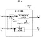
次に本発明のピッチ角制御方式について説明する。ピッチ角制御系の構成図を図4に示す。上位風車コントローラ25は、風速計24の計測した風速値を平均化演算器2501において時間平均し、風速の平均値v[m/sec ]を求める。上位風車コントローラ25は、回転速度指令演算器2502において、得られた風速の平均値v[m/sec ]からテーブル参照することにより、回転速度指令ω* を作成する。上位風車コントローラ25は、得られた回転速度指令ω*、ローター1の回転速度ω[rad/sec],発電電力P[W]から、発電電力指令P*[W]と、ブレード11のピッチ角指令φ*[度]を計算する。ピッチ角制御器111は、上位風車コントローラ25からのピッチ角指令φ* [度]に従って、ブレード11のピッチ角を制御する。本発明の特徴的な部分は、通常発電運転時と、異常時運転継続モード(本発明において、異常時運転継続モードとは、風力発電システムもしくは電力系統の異常を検出した後の運転モードを意味するものとする)において、ピッチ角制御、および発電電力制御の方式を切り替える点である。具体的には、通常発電運転時は、ピッチ角指令φ*、及び電力指令P*はそれぞれ、ピッチ角指令・電力指令演算器2503で作成された値を用いる(φ*=φ1*,P*=P1*)。異常時運転継続モードにおいては、ピッチ角指令は異常時ピッチ角指令演算器によって作成された値を用い(φ*=φ2*)、発電電力指令は0[W]とする(P*=0)。Next, the pitch angle control system of the present invention will be described. A configuration diagram of the pitch angle control system is shown in FIG. The upper
ピッチ角制御は、ローター1の回転速度を制御する役割を担う。ローター1の全体のエネルギーバランスは、数10で表される。 The pitch angle control plays a role of controlling the rotation speed of the
数10式中の記号の意味は、それぞれI[kg・m2]:回転体の慣性モーメント、ω[rad/sec]:ローター1の回転速度、Pin[W]:風からの入力パワー,P[W]:風力発電システムの発電電力、PLOSS:損失,t[sec] :時間,d/dt:微分演算子である。数10が示すように、ローター1の回転速度ωを制御するためには、ピッチ角制御器のピッチ制御によりPinを変化させるか、あるいは発電出力の制御によりPを変化させる必要がある。The meanings of the symbols in Equation 10 are respectively I [kg · m2 ]: moment of inertia of the rotating body, ω [rad / sec]: rotational speed of the
図5は、通常発電運転時における、風速vとピッチ角制御方式、および発電電力Pの関係を示したものである。風力発電システムは、その特性により発電運転が可能な風速領域がある。平均風速がvci(カットイン風速)より、大きい場合、発電運転を開始する。逆に、vciより風速が小さい場合、風力発電システムはピッチ角を所定の値に固定し、発電を行わず待機状態にいる。発電電力は、風速が大きくなるのに伴って増大し、vr (定格風速)以上では、ほぼ一定値になる。風速が、vCO(カットアウト風速)より大きい条件では、風力発電システムは、ブレード11を可能な限り風と平行にすることで(φ=0[度]、フェザー状態)、風の入力エネルギーを最小にし、発電を行わず待機状態にする。FIG. 5 shows the relationship between the wind speed v, the pitch angle control method, and the generated power P during normal power generation operation. A wind power generation system has a wind speed region in which power generation operation is possible due to its characteristics. When the average wind speed is larger than vci (cut-in wind speed), the power generation operation is started. Conversely, when the wind speed is smaller than vci , the wind power generation system fixes the pitch angle to a predetermined value and is in a standby state without generating power. Generated power, increased with the wind speed increases, vr in (the rated wind speed) or more, it becomes substantially constant value. Under conditions where the wind speed is greater than vCO (cutout wind speed), the wind power generation system can reduce the input energy of the wind by making the
発電運転時のピッチ角制御方式は、風速の大きさによって、大まかに次のように区別される。風速の平均値vがvci<v<vr の間では、ピッチ角は風向に対して最大値をとる(φ=30[度])、このようにすることで、ブレード11は風のエネルギーを最大限利用することができる。この間、風速の瞬時変動によって、ローターの回転速度が変化するが、風力発電システムが出力する発電電力Pを制御することによって、回転速度ωの変動を抑制する。一方、vr<v<vC0 の間では、上位風車コントローラ25は、発電電力指令Pを、定格発電電力値に固定する。風力発電システムの発電電力Pは、電力変換器28によって一定に制御される。この間、回転速度ωは、ピッチ角を変化させることで、制御される。The pitch angle control method during power generation operation is roughly classified as follows according to the wind speed. Between the average value v of the wind speed of vci <v <vr, the pitch angle is the maximum value with respect to the wind direction (phi = 30 [degrees]), By doing so, the
通常発電運転時における、ピッチ角指令φ*[度]と発電電力指令P*[W]の作成の詳細な手順を、図6に示す。ピッチ角指令演算器25032は、回転速度指令値ω* と、回転速度の検出値ωからピッチ角指令φ1*(=φ*)を作成する。同時に、発電電力指令演算器25034は、回転速度指令値ω* と、回転速度の検出値ω,発電電力量Pから、発電電力指令P1*(=P*)を作成する。FIG. 6 shows a detailed procedure for creating the pitch angle command φ* [degree] and the generated power command P* [W] during the normal power generation operation. The pitch
次に本発明における、異常検出時のピッチ角制御方式について説明する。異常検出時においては、風力発電システムは電力系統6への発電電力の供給を停止(P=0)する。このため数10から明らかなように、電力制御による回転速度制御が困難となり、比較的に応答速度の遅いピッチ角制御に依存した回転速度制御となるため、特別な制御が必要となる。異常の対象となる現象としては、系統電圧低下,系統電圧の上昇,変換器における過電流,系統周波数の変動、などが上げられる。 Next, the pitch angle control method at the time of abnormality detection in the present invention will be described. At the time of abnormality detection, the wind power generation system stops the supply of generated power to the power system 6 (P = 0). For this reason, as apparent from the equation (10), it is difficult to control the rotational speed by power control, and the rotational speed control depends on the pitch angle control having a relatively slow response speed, so that special control is required. Phenomena that are subject to abnormality include system voltage drop, system voltage rise, converter overcurrent, system frequency fluctuation, and the like.
まず異常現象のうち、系統電圧低下について説明する。電力系統では、落雷や送電線の樹木への接触,負荷の故障,人災による送電線の相間接触などにより、送電線の電圧が一時的に低下する場合がある。電圧の低下現象は、軽微な事故であれば、事故区間の遮断により、数秒以内に解消される。 First, of the abnormal phenomena, the system voltage drop will be described. In the power system, the voltage of the transmission line may temporarily decrease due to lightning strikes, contact of the transmission line with trees, load failure, phase-to-phase contact of the transmission line due to human disasters, and the like. The voltage drop phenomenon can be resolved within a few seconds by shutting off the accident section if it is a minor accident.
同様な系統電圧の異常現象として、系統電圧の上昇も発生しうる。系統電圧上昇の原因としては、負荷、発電機が電力系統に連系する際に瞬時的に発生する突入電流などによって引き起こされる。 As a similar abnormal phenomenon of the system voltage, an increase in the system voltage may occur. The cause of the system voltage rise is caused by an inrush current generated instantaneously when the load and the generator are connected to the power system.
このような、瞬時的な電圧低下,電圧上昇が発生した場合、風力発電システムは発電運転を停止する。これは、風力発電システム構成機器の保護のためである。 When such an instantaneous voltage drop or voltage rise occurs, the wind power generation system stops the power generation operation. This is to protect the wind power generation system components.
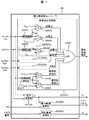
電圧の異常状態の検出は、電力変換器28を制御する電力変換器コントローラ26の内部で行う。電圧の異常状態の検出機構を、図7を用いて説明する。電力変換器コントローラ26は、数2,数5に示した演算を電力変換器コントローラ26内の電圧振幅演算器2602で行い、系統電圧振幅Vabs を得る。電力変換器コントローラ26は、内部に系統事故であると判断する電圧レベルVGFを保持しており、演算から求めた系統電圧振幅Vabsと、VGF を運転中に常時、比較している。比較は、電力変換器コントローラ26内部の比較演算器2604により行われ、Vabs<VGF が成り立った場合は、系統電圧が異常であると判断し、低電圧検出信号を発生する。系統電圧の過電圧の検出も同様の構成によって行われる。つまり電力変換器コントローラ26は内部に過電圧レベルVOVを保持しており、VabsとVOVを常に比較している。Vabs>VOVの関係が成り立った場合には、系統電圧が、過電圧状態であると判断し、過電圧検出信号を発生する。The detection of the abnormal state of the voltage is performed inside the
次に異常現象として、過電流現象について説明する。風力発電システムは、通常発電運転の範囲であれば、その出力する電流振幅は、定格電流以下である。しかしながら、系統事故などにより、定格電流を大きく上回る過大な電流が流れる場合がある。この現象を以降で過電流と呼ぶ。過電流時の電流振幅が、風力発電システム定格電流の1.5 〜2倍に達すると、電力変換器28の構成機器である半導体素子が、破壊される可能性がある。このため電力変換器や、風力発電システムの過電流検出時には、電力変換器28は瞬時に運転を停止し、風力発電システムが待機モードに移行する必要がある。なお。過電流の原因が電力系統の短時間の事故などであった場合は、過電流減少直後に、発電運転を再開する方が、電力系統安定化の観点から望ましい場合がある。 Next, an overcurrent phenomenon will be described as an abnormal phenomenon. If the wind power generation system is in the range of normal power generation operation, the output current amplitude is less than the rated current. However, an excessive current that greatly exceeds the rated current may flow due to a system fault or the like. This phenomenon is hereinafter referred to as overcurrent. If the current amplitude at the time of overcurrent reaches 1.5 to 2 times the rated current of the wind power generation system, the semiconductor element that is a component device of the
過電流の検出方法を、図7を用いて説明する。過電流は、電力変換器コントローラ26の過電流検出演算器26005aで検出される。電力変換器コントローラ26は、数1,数6に示した演算を、過電流検出演算器26005a内の電流振幅演算器2605で行い、出力電流の振幅Iabs を得る。電力変換器コントローラ26は、内部に過電流であると判断する電流振幅レベルIOCを保持している。電流振幅レベルIOCは、通常、発電システム定格電流振幅の1.5倍から2.0倍に設定される。電力変換器コントローラ26は、内部演算の比較演算器2606において、IOCとIabsを運転中に常時比較している。Iabs>IOCが成り立った場合は、過電流状態であると判断し、過電流検出信号を発生する。以上で電流測定器292により検出された風力発電システム全体の出力電流(IU,IV,IW)の過電流検出方法について説明したが、過電流検出演算器26005aと同様な方法を用いて、電力変換器28の過電流現象も検出する。系統側電力変換器283については、過電流検出演算器26005bにおいて、電流測定器293で検出した系統側電力変換器283の出力電流(IsU,IsV,IsW)を用いて、過電流を検出する。発電機側電力変換器281については、過電流検出演算器26005cにおいて、電流測定器294で検出した発電機側電力変換器281の出力電流(IgU,IgV,IgW)を用いて、過電流を検出する。The overcurrent detection method will be described with reference to FIG. The overcurrent is detected by an
系統周波数の変動も、異常検出の対象となる。電力系統の運用周波数は、それぞれの電力系統で決まっており、電力系統が通常の状態であれば、運用周波数から大きくずれることはない。しかしながら系統事故などにより、周波数が大きく変動する場合がある。このような場合、風力発電システムにおける電流制御が困難となる場合があるため、風力発電システム保護のため、発電運転を停止する。 Variations in system frequency are also subject to abnormality detection. The operating frequency of the power system is determined by each power system, and if the power system is in a normal state, it does not deviate significantly from the operating frequency. However, the frequency may fluctuate greatly due to a system fault or the like. In such a case, since current control in the wind power generation system may be difficult, the power generation operation is stopped to protect the wind power generation system.
系統周波数の変動の検出構成を、図7で説明する。電力変換器コントローラ26は、内部の系統周波数検出器2607において、系統電圧の検出値より電力系統の周波数ωSYSを検出する。電力変換器コントローラ26は、内部に周波数の上限ωSYSH、および下限 ωSYSLを保持している。電力変換器コントローラ26は、比較演算器2608、と比較演算器2609において、ωSYSとωSYSH,ωSYSLを、運転中に常時比較しており、ωSYS>ωSYSHあるいはωSYS<ωSYSLを検出したら、周波数変動大信号を発生する。A configuration for detecting fluctuations in the system frequency will be described with reference to FIG. In the internal
なお、図7に示した異常検出方法は、全て電力変換器コントローラ26の内部演算により行っているが、図8に示したような電気回路で構成しても良い。図8では、絶対値演算回路2610aと、コンパレータ2616aで構成した過電流検出回路26006aで過電流異常検出する。図8では、3相の電流検出値IU,IV,IW から、絶対値演算回路2610a,2611a,2612aとダイオード2613a,2614a,2615aを用いることで、電流のピーク値を検出する。この電流ピーク値を、コンパレータ2616aにおいて過電流レベルIOCと比較することにより、過電流を検出する。なお、過電流レベルIOCは、5Vの電圧源と、抵抗器2618a,可変抵抗器2617aにより設定される。電力変換器28の過電流も、同様の回路構成をもつ過電流検出回路26006bおよび過電流検出回路26006cによって検出する。なお、図8には示していないが、過電圧現象も同様な電気回路構成で検出することが可能である。The abnormality detection method shown in FIG. 7 is all performed by the internal calculation of the
電力変換器コントローラ26は、上記の異常検出信号(過電流,電圧異常,周波数異常)を少なくともひとつ検出した場合は、電力変換器を動作させるゲートパルス信号を停止する。この動作をゲートブロックと呼ぶ。同時に、上位風車コントローラに異常検出信号を伝達する。上位風車コントローラは、異常検出信号を検出した場合、風力発電システム全体を、異常時運転継続モードに移行させる。 The
本発明における、異常時運転継続モード中のピッチ角制御の方式について、以下で説明する。異常状態が解消された後に、風力発電システムがすぐ発電運転状態に移行するためには、異常時運転継続モード中においても、ローター1の回転速度を発電運転可能な範囲に維持しておくことが必要となる。ローター1の回転速度制御は、ピッチ角制御と発電電力制御によって行われる。ピッチ角制御は図3に示したピッチ角制御器111で行われる。ピッチ角制御器111は電動モーターかあるいは油圧駆動系などによって構成される。ピッチ角の制御は、フェザー状態(φ=0[度])から最大角(φ=30[度])まで変化させるのに、数十秒程度必要である。一方、発電電力制御は、0から定格まで変化させるのに、数100msec 程度である。このため、回転速度制御は、ピッチ角制御よりも発電電力制御のほうが、応答が速い。 The pitch angle control method during the abnormal operation continuation mode in the present invention will be described below. In order for the wind power generation system to immediately shift to the power generation operation state after the abnormal state is resolved, it is necessary to maintain the rotation speed of the
異常状態検出後の異常時運転継続モード中は、風力発電システムは発電運転を停止するため、電力系統に発電電力を供給しない。このとき、数10の中においてP=0となるため、応答が遅いピッチ角制御のみで回転速度を制御しなければならず、通常のピッチ制御のままでは、回転速度が運転範囲を逸脱しやすい。特に、定格発電運転中に異常状態を検出した場合、数10の中のPが定格発電電力から0[W]まで急激に変化するため、回転速度ωが急激に上昇する。回転速度ωの上昇を抑えるためには、通常の発電運転時とは異なったピッチ角制御方式が必要となる。 Since the wind power generation system stops the power generation operation during the abnormal operation continuation mode after the abnormal state is detected, the generated power is not supplied to the power system. At this time, since P = 0 in Equation 10, the rotation speed must be controlled only by the pitch angle control with a slow response, and the rotation speed easily deviates from the operating range with the normal pitch control. . In particular, when an abnormal state is detected during rated power generation operation, P in Formula 10 rapidly changes from the rated generated power to 0 [W], and thus the rotational speed ω increases rapidly. In order to suppress the increase in the rotational speed ω, a pitch angle control method different from that during normal power generation operation is required.
図9に、異常状態検出後の異常時運転継続モード中のピッチ角制御方式の一例を示す。異常時運転継続モード中は、回転速度の検出値ωに応じて、ピッチ角の制御方式を切り替える。具体的には、回転速度に二つのレベルωa,ωbをもうけ、この二つのレベルと回転速度検出値ωを比較することで、ピッチ角制御方式を切り替える。なお、ωa,ωbと、運転可能な回転速度の上限ωH,下限ωLの間には、数11に示すような関係が成り立つ。FIG. 9 shows an example of the pitch angle control method during the abnormal operation continuation mode after the abnormal state is detected. During the abnormal operation continuation mode, the pitch angle control method is switched according to the detected value ω of the rotational speed. Specifically, the pitch angle control method is switched by providing two levels ωa and ωb to the rotational speed and comparing the two levels with the rotational speed detection value ω. Note that the relationship shown in
回転速度の検出値がωa≦ω≦ωbの関係にある間は、ピッチ制御は、PI制御器25063によって行われる。PI制御器25063は、回転速度の目標値ω* と回転速度検出値ωの差分を、比例積分演算することにより、ピッチ角指令φ2*(=φ* )を決定する。ω<ωa の場合には、ピッチ角指令選択器25064は、ピッチ角指令として最も風のエネルギーを受ける角度φ2*=30[度]を選択する。同様に、ω>ωb の場合には、ピッチ角指令選択器25064は、ピッチ角指令として最も風のエネルギーを受けない角度φ2*=0[度]を選択する。While the detected value of the rotational speed is in the relationship of ωa ≦ ω ≦ ωb , the pitch control is performed by the
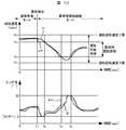
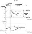
図10に、回転速度とピッチ角の時間変化の様子を示す。図10では、時刻t1 に異常状態を検出し、発電を停止、以降は異常時運転継続モードにある。異常検出の瞬間に、回転速度は、ω>ωb関係にあるため、ピッチ各指令としてφ*=0[度]が選択される。このようにすることで、回転速度が運転可能領域の上限に近づいた際、風の入力エネルギーを急速に減衰させることができるので、回転速度が低下し、回転速度が回転速度の上限ωHを上回ることを防止できる。時刻t2<t<t3の間は、ωa<ω<ωb の関係があるため、PI制御によるピッチ角指令に従う。t3<t<t4の間は、ω<ωa であり、運転速度の下限に達しやすい領域にある。この際は、ピッチ角指令としてφ* =30[度]が選択される。これにより、風のエネルギー入力エネルギーを急速に増大させることができるので、回転速度が上昇し、回転速度ωが回転速度の下限ωLを下回ることを防止できる。FIG. 10 shows how the rotation speed and the pitch angle change with time. In FIG. 10, an abnormal state is detected at time t1 and power generation is stopped. At the moment of abnormality detection, the rotational speed has a relationship of ω> ωb , so that φ* = 0 [degree] is selected as each pitch command. In this way, when the rotational speed approaches the upper limit of the operable range, the input energy of the wind can be rapidly attenuated, so that the rotational speed decreases, and the rotational speed exceeds the upper limit ωH of the rotational speed. It can be prevented from exceeding. Between times t2 <t <t3, since there is the relationship ωa <ω <ωb, according to the pitch angle command according to PI control. During t3 <t <t4 , ω <ωa, which is in a region where the lower limit of the operation speed is easily reached. In this case, φ* = 30 [degrees] is selected as the pitch angle command. Thereby, since the energy input energy of the wind can be increased rapidly, the rotation speed can be increased and the rotation speed ω can be prevented from falling below the lower limit ωL of the rotation speed.
異常時運転継続モード中の他のピッチ角制御方式として、図11に示す方式を用いてもよい。図11に示した方式では、異常時運転継続モード中は、回転速度の検出値ωに応じて、予め定められたピッチ角指令を選択する。具体的には、ω<ωaのときはφ*=30[度]を、ωa≦ω≦ωb のときにはφ*=15[度]、ω>ωbのときにはφ*=0[度]を選択する。As another pitch angle control method during the abnormal operation continuation mode, the method shown in FIG. 11 may be used. In the method shown in FIG. 11, during the abnormal operation continuation mode, a predetermined pitch angle command is selected according to the detected value ω of the rotational speed. Specifically, omega <omega a is φ* = 30 [degrees] whena, when theω a ≦ ω ≦ ω b φ * = 15 [ degrees], omega> when the ωb φ* = 0 [degrees Select.
図11に示したピッチ角制御方式を行った際の、回転速度ωとピッチ角φの動きを図12に示す。図12の例では、時刻t1 に異常状態を検出し、発電を停止、以降は異常時運転継続モードにある。異常時運転継続モード中は、回転速度の大きさに応じて、3段階のピッチ角指令を選択する。時刻t1<t<t2 の間は、回転速度がω>ωbとなり、運転可能領域の上限に近いため、ピッチ角指令としてφ* =0[度]を選択することで、風の流入エネルギーを減衰させ、回転速度の上限逸脱を防止する。逆に、t3<t<t4の間では、回転速度がω<ωa となり、運転可能領域の下限に近づいたため、ピッチ角指令としてφ* =30[度]を選択する。これにより、風の流入エネルギーを増大させ、回転速度の下限を逸脱するのを防止する。FIG. 12 shows the movements of the rotational speed ω and the pitch angle φ when the pitch angle control method shown in FIG. 11 is performed. In the example of FIG. 12, an abnormal state is detected at time t1 and power generation is stopped, and thereafter, the operation continues in the abnormal time operation mode. During the abnormal operation continuation mode, a three-step pitch angle command is selected according to the magnitude of the rotational speed. During the time t1 <t <t2 , the rotational speed is ω> ωb , which is close to the upper limit of the operable range. Therefore, by selecting φ* = 0 [degree] as the pitch angle command, the inflow of wind Attenuates energy and prevents the rotation speed from deviating from the upper limit. Conversely, between t3 <t <t4, next to the rotational speed omega <omegaa, since close to the lower limit of the operating region, selects φ* = 30 [degrees] as the pitch angle command. This increases the inflow energy of the wind and prevents the rotation speed from deviating from the lower limit.
また、異常時運転継続モード中の他のピッチ角制御方式としては、図13に示す方式を用いてもよい。図13に示すピッチ角制御方式では、異常時運転継続モード中は回転速度指令値ω*を、風速にかかわらず、一定値ωCに固定する。ωC は運転可能な回転速度の上限ωHと下限ωLの中間値程度に設定する。ピッチ角指令φ2は、この回転速度指令値ωCと、回転速度の検出値ωの差分にPI制御演算を行ったもので作成される。図14に、図13に示したピッチ角制御を行った場合の、回転速度ωとピッチ角φの動きを示す。図14の例では、時刻t1 に異常状態を検出し、発電を停止、以降は異常時運転継続モードにある。異常時運転継続モード中は、回転速度の目標値ω* は、風速によらず一定値となる。このようにすることで、ローター1の回転速度が、運転可能な領域を逸脱しにくくなる。なお、以上の構成においては、ローター1の回転速度が高い領域においては、ピッチ角をフェザー状態(ピッチ角φ=0[度])に固定したが、フェザー状態付近の所定値に固定しても、同様な過回転防止効果が得られる。Further, as another pitch angle control method in the abnormal operation continuation mode, the method shown in FIG. 13 may be used. In the pitch angle control method shown in FIG. 13, the rotational speed command value ω* is fixed to a constant value ωC regardless of the wind speed during the abnormal operation continuation mode. ωC is set to an intermediate value between the upper limit ωH and the lower limit ωL of the operable rotational speed. The pitch angle command φ2 is created by performing PI control calculation on the difference between the rotational speed command value ωC and the detected rotational speed value ω. FIG. 14 shows the movement of the rotational speed ω and the pitch angle φ when the pitch angle control shown in FIG. 13 is performed. In the example of FIG. 14, an abnormal state is detected at time t1 , power generation is stopped, and thereafter, the operation continues in the abnormal time operation mode. During the abnormal operation continuation mode, the target value ω* of the rotational speed is a constant value regardless of the wind speed. By doing in this way, it becomes difficult for the rotational speed of the
なお、異常現象のうち系統電圧低下においては、風力発電システムの制御電源を、電力系統から供給できなくなる。このため、図15に示したように、風力発電システムを構成する制御器(上位風車コントローラ25,ピッチ角制御器111,電力変換器コントローラ26など)は、それぞれ補助電源を備えている。電力系統の電圧低下現象が発生していない場合は、制御器の電力は、電力系統の交流6.6kV(あるいは1.4kV)から、降圧トランス41により交流200V(あるいは交流400V)に降圧され、補助電源30a,30b,30cを介して供給される。補助電源30a,30b,30cは、内部に蓄電池などの蓄電設備をそなえており、電力系統の電圧低下現象が発生していない場合は、電力系統から制御器へ制御電源を供給し、同時に蓄電設備への充電動作を行っている。 In the abnormal phenomenon, when the system voltage is reduced, the control power of the wind power generation system cannot be supplied from the power system. For this reason, as shown in FIG. 15, the controllers (the upper
電力系統の電圧低下現象が発生し、電力系統から制御器(上位風車コントローラ25,ピッチ角制御器111,電力変換器コントローラ26など)への電力供給ができなくなった場合、補助電源30a,30b,30cはそれぞれ内部の蓄電設備から、制御電源に電力を供給する。このような補助電源を持つ構成により、系統電圧低下中であっても、制御器は電力を確保でき、異常時運転継続モードにおける動作が可能となる。 When a voltage drop phenomenon of the power system occurs and power cannot be supplied from the power system to the controller (the upper
なお、以上で説明したような異常時運転継続モード中のピッチ角制御方式は、二次励磁発電機型風力発電システムの他に、図16に示す永久磁石発電機型風力発電システム,誘導発電機型風力発電システム、図17に示す直流励磁同期発電機型風力発電システムなどにも適用が可能である。 Note that the pitch angle control method during the abnormal operation continuation mode as described above is not limited to the secondary excitation generator type wind power generation system, but also the permanent magnet generator type wind power generation system and induction generator shown in FIG. The present invention can also be applied to a type wind power generation system, a direct current excitation synchronous generator type wind power generation system shown in FIG.
以上に説明してきたように、異常検出後の異常時運転継続モードにおいてピッチ角制御方式を通常の発電運転時の制御方式から異常時運転継続モードに切り替え、ピッチ角指令を風車の回転速度に応じて切り替える、または、回転速度を一定の目標値に制御するためにピッチ角指令を調整する。このようなピッチ角制御の方法により、ローター1の回転速度制御をピッチ角の調整によってのみ行う必要がある異常時運転継続モード中においても、ローター1の回転速度を運転可能領域に収めることが容易となり、異常状態が解消された後、すぐに通常の発電運転状態に移行することが可能となる。これにより、風力発電システムの発電運転時間を延ばすことができ、発電量が増加する。また系統事故直後の電力供給により、電力系統全体の安定化に寄与できる。 As described above, the pitch angle control method is switched from the normal power generation operation control method to the abnormal operation continuation mode in the abnormal operation continuation mode after the abnormality is detected, and the pitch angle command is changed according to the rotational speed of the windmill. The pitch angle command is adjusted in order to control the rotation speed to a constant target value. By such a pitch angle control method, the rotational speed of the
本発明の実施例について説明する。本実施例においては、ピッチ角制御方式を、系統電圧の低下率に応じて変更する。 Examples of the present invention will be described. In this embodiment, the pitch angle control method is changed according to the rate of decrease in the system voltage.
本発明は、図1,図2に示したような、電力変換器28を構成要素にもち、発電電力の制御が可能な風力発電システムに適用できる。通常発電運転時のピッチ角制御,発電電力の制御は、実施例1に示した通りであるので、説明は省略する。 The present invention can be applied to a wind power generation system having the
本発明における、系統電圧低下中の風力発電システムの運転方式について、以下で説明する。電力系統では、落雷や送電線の樹木への接触,負荷の故障,人災による送電線の相間接触などにより、送電線の電圧が一時的に低下する場合がある。電圧の低下現象は、軽微な事故であれば、事故区間の遮断により、数秒以内に解消されることが多い。 The operation method of the wind power generation system during the system voltage drop in the present invention will be described below. In the power system, the voltage of the transmission line may temporarily decrease due to lightning strikes, contact of the transmission line with trees, load failure, phase-to-phase contact of the transmission line due to human disasters, and the like. In the case of a minor accident, the voltage drop phenomenon is often resolved within a few seconds by interrupting the accident section.
風力発電システムが、系統電圧低下中においても発電電力を電力系統に供給すると、以下のような利点がある。つまり、数10に示したように風力発電システムのローター1の回転速度は、主に風からの入力パワーPin[W]と発電システムの発電電力P[W]によって決まる。例えば系統事故中において、電力系統に発電電力を供給できない場合、数10中においてP=0となるため、回転速度ωが急激に上昇する。一方、系統事故中であっても、電力系統へ発電電力Pを供給できれば、回転速度ωの上昇が緩慢になる。このような発電電力の大きさの違いによって、回転速度ωの上昇速度は変化する。When the wind power generation system supplies the generated power to the power system even when the system voltage is lowered, the following advantages are obtained. That is, as shown in Equation 10, the rotational speed of the
つぎに系統電圧と発電電力Pの関係について説明する。系統電圧瞬低中は数9に示した系統電圧Vabs=|Vd|が低下するため、数7式に示したように、事故前と同じ電流Idを流しても、発電電力Pは小さくなる。発電電力Pを事故前と同じ値に保つためには、出力電流Id を増加させる必要があるが、電力変換器28や、発電機からの制約により、限界がある。電力変換器28の出力できる電流値の最大値をIMAX [Arms]とした場合、数12式に示すように、風力発電システムの発電電力量の最大値PMAX [W]は系統電圧に比例する。Next, the relationship between the system voltage and the generated power P will be described. During grid voltage transient sag system voltage Vabs = shown in several 9 | Vd | order decreases, as shown in equation (7), also conduct the same current Id and before the accident, the generated power P is Get smaller. In order to keep the generated power P at the same value as before the accident, it is necessary to increase the output current Id , but there is a limit due to restrictions from the
このため、回転速度上昇防止のためのピッチ角制御方式を、系統電圧の低下率によって、それぞれ変更する必要がある。例えば、系統電圧が0になる事故の場合、数7中のVdはほぼ0であるから、電力系統に供給できる電力Pも、ほぼ0となる。このため、回転速度の上昇を抑えるためには、数10中の入力パワーPinを急速に減少させる必要がある。つまり、ピッチ角を風向と平行になる方向(フェザー方向)に変化させる必要がある。For this reason, it is necessary to change the pitch angle control system for preventing the rotation speed from increasing depending on the rate of decrease of the system voltage. For example, in the case of an accident in which the system voltage becomes 0, Vd in
一方、系統電圧が通常時の80%程度までしか低下しない時は、系統異常時であっても、ほぼすべての発電電力を電力系統に供給できる。つまり、数10中の発電電力Pの減少が少なく、回転速度上昇も緩やかである。ピッチ角制御も、入力パワーPinを急速に減少させる必要が無いため、図4に示した通常の制御方式を維持する、あるいは風速条件がvci<v<vrの範囲であっても、回転速度が上限を超えた場合のみ、過回転を抑えるピッチ角制御を行う程度で十分である。On the other hand, when the system voltage drops only to about 80% of the normal time, almost all generated power can be supplied to the power system even when the system is abnormal. That is, the decrease in the generated power P in Equation 10 is small, and the increase in rotational speed is also gradual. Pitch control also, it is not necessary to reduce rapidly the input power Pin, be in a range to maintain the normal control system shown in FIG. 4, or wind conditions vci <v of <vr, Only when the rotational speed exceeds the upper limit, it is sufficient to perform pitch angle control that suppresses over-rotation.
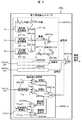
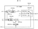
本実施例におけるピッチ角制御系と電力制御器系の構成図を図18に示す。上位風車コントローラ25dは、風速計24dの計測した風速値を平均化演算器2501dにおいて時間平均し、風速の平均値v[m/sec ]を求める。上位風車コントローラ25dは、回転速度指令演算器2502dにおいて、得られた風速の平均値v[m/sec ]からテーブル参照することにより、回転速度指令ω* を作成する。上位風車コントローラ25dは、得られた回転速度指令ω* ,ローター1の回転速度検出値ω[rad/sec],発電電力P[W],系統電圧振幅Vabs[W]から、発電電力指令P*[W]とともに、ブレード11のピッチ角指令φ*[度]を計算する。ピッチ角制御器111dは、上位風車コントローラ25dからのピッチ角指令φ*[度]に従って、ブレード11のピッチ角を制御する。FIG. 18 shows a configuration diagram of the pitch angle control system and the power controller system in the present embodiment. The
ピッチ角指令・電力指令演算器2503dの動作について、図19を用いて説明する。本発明では、電圧低下の大きさにより、ピッチ角制御方式を切り替えることを特徴とする。具体的には、系統事故中において、系統電圧を3段階に分けて、それぞれの領域においてピッチ角制御方式を変更する。通常時の系統電圧を100%とすると、送電線の電圧範囲は、系統運用者の規定によって変わるが、およそ90%〜110%程度である。ここではVGF=90%以下を系統事故状態であると判断し、さらに系統事故時の期間を、系統電圧の大きさに応じて三つに分ける。The operation of the pitch angle command /
例えば系統電圧がVGF(=90%)〜Vabs2(=80%)の間は、系統事故中であっても、ほぼ全ての発電電力を電力系統に供給できるため、事故による影響は小さく、回転速度の上昇はほとんどない。ピッチ角制御は、風速に応じた通常運転時の制御方式を継続し、ωとω*に応じて、ピッチ角指令を作成する。For example, when the system voltage is between VGF (= 90%) and Vabs2 (= 80%), almost all generated power can be supplied to the power system even during a systemfault . There is almost no increase in rotational speed. In the pitch angle control, a control method during normal operation according to the wind speed is continued, and a pitch angle command is created according to ω and ω* .
系統電圧がVabs2[%](80%)〜Vabs1[%](20%)の間は、ピッチ角をあらかじめ設定しておいた角度φ=15[度]まで急速に変化させて、固定する。なお、この所定の角度は、ピッチ角最大値とフェザー状態の中間程度の値である。このようなピッチ角制御を行うことで、風の入力エネルギーを一部逃がすことで過回転を防止し、かつ事故期間中もローターの回転を維持して、事故復帰後すぐに通常発電状態に移行することを可能とする。When the system voltage is between Vabs2 [%] (80%) and Vabs1 [%] (20%), the pitch angle is rapidly changed to a preset angle φ = 15 [degrees] and fixed. To do. Note that the predetermined angle is a value that is approximately between the maximum value of the pitch angle and the feather state. By controlling the pitch angle in this way, part of the input energy of the wind is released to prevent over-rotation and the rotation of the rotor is maintained even during the accident period. It is possible to do.
系統電圧がVabs1[%](=20[%])未満の場合は、電力系統にほとんど発電電力を供給できないため、ローター1の回転速度ωが急速に上昇する。回転速度の上昇を抑えるため、ピッチ角制御器111はピッチ角をフェザー状態φ* =0[度]まで急速に変化させる。なお、発電電力指令P*に関しては、最大電力指令演算器25037dにより、数7式による発電可能な最大発電電力量Pmax が演算され、リミッタ25036dによって、発電電力指令P*を限定する。When the system voltage is less than Vabs1 [%] (= 20 [%]), almost no generated power can be supplied to the power system, so the rotational speed ω of the
図18,図19に示したピッチ角制御方式を適用した場合の、ピッチ角指令の時間変化を図20に示す。図20は、横軸が時間を、縦軸が系統電圧振幅とピッチ角指令を示している。図20では、時刻t1に系統電圧振幅が、Vabs<VGFとなるが、ピッチ角制御方式は、通常の発電運転時と同様に、回転速度に応じたピッチ角制御を行う。時刻t2 <t<t3、およびt4<t<t5の間は、系統電圧振幅がVabs1<Vabs<Vabs2であるため、ピッチ角指令φ*を15[度]に固定する。同様に、時刻t3<t<t4 の間は、系統電圧振幅がVabs<Vabs1であるため、ピッチ角指令φ*を0[度]に固定する。このようなピッチ角制御を行うことで、回転速度が運転範囲を逸脱するのを、防止しやすくなる。FIG. 20 shows a time change of the pitch angle command when the pitch angle control method shown in FIGS. 18 and 19 is applied. In FIG. 20, the horizontal axis indicates time, and the vertical axis indicates the system voltage amplitude and pitch angle command. In FIG. 20, the system voltage amplitude becomes Vabs <VGF at time t1 , but the pitch angle control method performs the pitch angle control according to the rotation speed as in the normal power generation operation. Between times t2 <t <t3 and t4 <t <t5 , the system voltage amplitude is Vabs1 <Vabs <Vabs2 , so the pitch angle command φ* is fixed to 15 degrees. . Similarly, during the time t3 <t <t4 , the system voltage amplitude is Vabs <Vabs1 , so the pitch angle command φ* is fixed to 0 [degrees]. By performing such pitch angle control, it is easy to prevent the rotation speed from deviating from the operating range.
なお、ピッチ角制御方式を切り替える系統電圧の値(VGF,Vabs1,Vabs2など)は、風力発電システムが連系する電力系統、あるいは風力発電システムの連系容量,風力発電システムの特性によって、それぞれ変更することが可能である。またピッチ角制御方式を切り替える際の系統電圧レベル、およびピッチ角の固定レベルは3つ以上であってもよい。Note that the value of the system voltage for switching the pitch angle control system (VGF, such as Vabs1, Vabs2), the power grid wind power generation system interconnection or interconnection capacity of the wind power generation system, the characteristics of the wind power generation system, , Each can be changed. Further, the system voltage level and the fixed pitch angle level when switching the pitch angle control method may be three or more.
また、本発明は、図3に示す二次励磁型風力発電システム、図16に示す永久磁石発電機型風力発電システム、誘導発電機型風力発電システム、図17に示す直流励磁同期発電機型風力発電システムなどに適用が可能である。 The present invention also includes a secondary excitation type wind power generation system shown in FIG. 3, a permanent magnet generator type wind power generation system shown in FIG. 16, an induction generator type wind power generation system, and a DC excitation synchronous generator type wind power shown in FIG. It can be applied to power generation systems.
以上のような系統電圧低下率に応じて、ピッチ角制御方式を選択することで、瞬時系統電圧低下時もローターの過回転を抑制することができ、事故復帰直後の瞬時発電運転再開が可能となる。これにより、風力発電システムの運転時間が長くできるため、発電量が増加する。また系統事故直中、系統事故除去直後の電力供給により、系統全体の安定化に寄与できる。 By selecting the pitch angle control method according to the system voltage drop rate as described above, it is possible to suppress overrotation of the rotor even when the instantaneous system voltage drops, and it is possible to resume instantaneous power generation operation immediately after the accident recovery Become. Thereby, since the operation time of a wind power generation system can be lengthened, electric power generation amount increases. In addition, power supply immediately after a system fault and immediately after the system fault is removed can contribute to the stabilization of the entire system.
本発明の第3の実施例について図21,図22,図23,図24を用いて説明する。図21は永久磁石発電機を用いた、本実施例による風力発電システムの構成を示している。制御系は、主に風車全体の動きを制御する上位風車コントローラ25e,電力変換器28eを制御する電力変換器コントローラ26eによって構成されている。上位風車コントローラ25eは、風速計24eで計測した風速、ローター1の回転速度ω[rad/sec]などから、発電電力指令や、ブレード11eのピッチ角指令を計算する。 A third embodiment of the present invention will be described with reference to FIGS. 21, 22, 23, and 24. FIG. FIG. 21 shows the configuration of a wind power generation system according to this embodiment using a permanent magnet generator. The control system is mainly composed of a high-order windmill controller 25e that controls the movement of the entire windmill and a
風力発電システムの発電電力は、電力変換器28eによって制御される。電力変換器28eは主に発電機側電力変換器281e,系統側電力変換器283e,平滑化コンデンサ282eで構成される。発電機側電力変換器281eと系統側電力変換器283eは、IGBTなどの半導体スイッチング素子を用いて構成する。通常運転時は、発電機側電力変換器281eは、有効電力制御を行うことで、上位風車コントローラ25eの有効電力指令Pに従って発電電力を制御している。発電機側電力変換器281eは、同時に無効電力制御を行うことで、永久磁石型発電機23eの端子電圧を制御している。また系統側電力変換器283eは、電力変換器28eの直流部の電圧制御を行うことで、電力系統に発電電力を供給する。また系統側電力変換器283eは、同時に電力系統へ出力する無効電力も制御する。 The power generated by the wind power generation system is controlled by the
電力変換器コントローラ26eは、風力発電システムの連系点に設置した電圧測定器291eおよび、電流測定器292eから、それぞれ3相の交流電圧値VU,VV,VW[V]、3相の電流値IU,IV,IW [A]を内部に取り込む。電力変換器コントローラ26eは、内部でこれらの電圧,電流信号から、電圧振幅値Vabs [rms],電流振幅値Iabs [Arms],有効電力(発電電力)P[W],無効電力Q[Var]などを演算する。Vabs[Vrms]とIabs[Arms]は、具体的には数13,数14に従って演算される。The
電力変換器コントローラ26eは、演算した電力変換器出力電流振幅Iabsを、常に電力変換器コントローラ26e内部の所定値ICLR,IOCと比較し、系統側電力変換器283eの過電流現象を検出している。なお所定値には、数15に示すような関係がある。The
系統側電力変換器283eは、図22に示したように、IGBT2833eと還流ダイオード2832e、および電力変換器コントローラ26eから受信した、ゲートパルス信号に従ってIGBTを駆動するゲート駆動回路2831eとで構成されている。IGBT2833eはある一定値以上の電流を流したままでスイッチング動作を行うと、破損する可能性が高まる。そのため、電力変換器コントローラ26eは、過電流を検出した際、系統側電力変換器283eにスイッチング動作を停止させる信号を送る。過電流が発生する原因としては、系統事故や電力変換器構成機器の短絡事故、あるいは電力変換器コントローラ26eの誤作動などがある。 As shown in FIG. 22, system-
図23に、系統事故による電圧低下現象が起こった場合の、Vabs検出値とIabs検出値の動きを示す。図23では、時刻t0に系統事故が発生し、それ以前では、系統電圧Vabsは正常(Vabs=100%)であり、また風力発電システムは定格電力で発電している(Iabs=100%)ものとする。時刻t0以降から電圧低下が始まり、このため系統側電力変換器283eの電流制御性能が悪化し、電流値振幅Iabs が増加をはじめる。系統電圧の低下速度が速い場合、Iabsの増加が早く、図23に示したように、過電流検出Iabs>IOC(時刻t1)のほうが、系統事故検出Vabs<90[%](時刻t2) より早く起こる。このため、風力発電システムは、まず過電流対応の制御モードに制御方式を切り替え、その後、系統電圧低下対応の制御方式に切り替える必要がある。23, when that occurred the voltage drop phenomenon due to a grid fault, showing the movement of the Vabs detection value and Iabs detection value. In FIG. 23, a system fault occurs at time t0 , and before that, the system voltage Vabs is normal (Vabs = 100%), and the wind power generation system generates power at the rated power (Iabs = 100%). The voltage drop starts after time t0 , so that the current control performance of the grid-
図24に、風力発電システムの、過電流検出時の運転のフローチャートを示す。以下で、過電流検出から、発電運転再開までの運転方法の時系列変化を説明する。
1)過電流検出時
電力変換器コントローラ26eが過電流を検出した際、系統側電力変換器283eはゲートブロックをする。系統電圧低下による過電流であれば、ゲートブロックにより電流振幅Iabs は急速に減少する。電流振幅が減少しなかった場合は、過電流発生の原因が、風力発電システム構成機器の故障である可能性が高いため、上位風車コントローラ25eは、遮断器5eに開信号を送り、風力発電システムを停止状態に移行させる。FIG. 24 shows a flowchart of the operation of the wind power generation system when an overcurrent is detected. Hereinafter, the time series change of the operation method from the overcurrent detection to the restart of the power generation operation will be described.
1) At the time of overcurrent detection When the
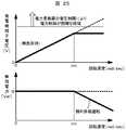
一方、発電機側電力変換281eは、永久磁石型発電機23eの回転速度により、系統側過電流検出時の運転方法が異なる。永久磁石型発電機23eは、回転速度の増加とともに、誘起電圧が増大する。誘起電圧が発電機側電力変換器281eの出力電圧より大きくなる場合、電力制御ができなくなるため、弱め界磁運転と呼ぶ制御を行う。これは、発電機側電力変換器281eが、永久磁石型発電機23eの固定子に供給する無効電力を制御することにより、端子電圧を下げる運転方式のことである。弱め界磁運転時の発電機端子電圧と無効電力の関係を、図25を用いて説明する。永久磁石型発電機23eの発電機端子電圧は、無負荷時においては回転速度とほぼ比例して増大する。このため、ある回転速度以上では、発電機端子電圧が、発電機側電力変換器281eの出力電圧より大きくなり、発電機の電力制御が困難になる。このため、予め定めた回転速度ωc[rad/sec]より回転速度が大きい運転領域では、発電機側電力変換器281eが、発電機に対して無効電力を供給する。無効電力の供給により、発電機端子電圧の上昇が抑制され、回転速度が高い領域でも、発電機側電力変換器281eによる電力制御を可能とすることができる。なお、図25においては、無効電力を回転速度に対して直線的に出力しているが、弱め界磁運転の無効電力出力方式はこれに限定されるものではなく、別の出力方式を行っても、同様な効果が得られる。 On the other hand, the generator-side power conversion 281e differs in the operation method when detecting the system-side overcurrent depending on the rotational speed of the permanent magnet generator 23e. In the permanent magnet generator 23e, the induced voltage increases as the rotational speed increases. When the induced voltage becomes larger than the output voltage of the generator-side power converter 281e, power control cannot be performed, so control called field weakening operation is performed. This is an operation method in which the generator-side power converter 281e reduces the terminal voltage by controlling the reactive power supplied to the stator of the permanent magnet generator 23e. The relationship between the generator terminal voltage and reactive power during field-weakening operation will be described with reference to FIG. The generator terminal voltage of the permanent magnet generator 23e increases substantially in proportion to the rotational speed when there is no load. For this reason, at a certain rotational speed or higher, the generator terminal voltage becomes larger than the output voltage of the generator-side power converter 281e, making it difficult to control the power of the generator. For this reason, in the operation region where the rotational speed is higher than the predetermined rotational speed ωc [rad / sec], the generator-side power converter 281e supplies reactive power to the generator. The supply of reactive power suppresses an increase in the generator terminal voltage and enables power control by the generator-side power converter 281e even in a region where the rotational speed is high. In FIG. 25, the reactive power is output linearly with respect to the rotational speed, but the reactive power output method of the field weakening operation is not limited to this, and another output method is performed. The same effect can be obtained.
系統側電力変換器283eで過電流が発生した場合、系統側電力変換器283eはゲートブロックをするため、電力系統に電力を供給できない。このため、電力変換器28eの直流部の電圧上昇を抑制するために、発電機側電力変換器281eは、永久磁石型発電機23eからの有効電力の流入を止める必要がある。回転速度が高い場合は、発電機側電力変換器281eは、永久磁石型発電機23eへの無効電力供給を継続しなければならない場合がある。なぜなら、回転速度が上昇し、電力変換器28eの直流電圧より永久磁石型発電機23eの誘起電圧の方が高くなった場合、発電機側電力変換器281eの還流ダイオードを介して、発電機のエネルギーが直流部に流れ込み、直流部の電圧を上昇させてしまうからである。このような場合、弱め界磁運転により端子電圧を下げ、直流部の電圧上昇を抑えることができる。よって、回転速度が高い場合には、発電機側電力変換器281eは、永久磁石型発電機23e端子の有効電力を0[W]に制御し、同時に無効電力制御による弱め界磁運転は継続する。これにより、事故期間中の直流部電圧上昇を抑制し、事故復帰直後の発電機側の電流制御,電力制御が可能となる。なお、永久磁石型発電機23eの回転速度が低く、発電機端子電圧が、電力変換器28eの直流部電圧より低い場合、直流部充電が起こらないため、発電機側電力変換器281eは、ゲートブロックを行い、停止してもよい。 When an overcurrent occurs in the system-
また、永久磁石型発電機23eの電圧特性によっては、強め界磁運転を行う必要がある。永久磁石型発電機23eは、回転速度の減少とともに、誘起電圧が減少する。このため、回転速度が小さい領域で電力制御を行う場合、多くの電流量が必要となる場合がある。電流量が発電機側電力変換器281eの電流容量制限を上回る場合、電力制御が困難となる。強め界磁運転について示したのが、図26である。強め界磁運転では、回転速度が小さい領域で、発電機端子電圧が上昇する方向に無効電力を出力する。これにより、回転速度が小さい領域でも発電機側電力変換器281eの出力する電流量が少なくてすみ、電力制御が可能となる。 Further, depending on the voltage characteristics of the permanent magnet generator 23e, it is necessary to perform strong field operation. In the permanent magnet generator 23e, the induced voltage decreases as the rotational speed decreases. For this reason, when power control is performed in a region where the rotational speed is low, a large amount of current may be required. When the amount of current exceeds the current capacity limit of the generator-side power converter 281e, power control becomes difficult. FIG. 26 shows the strong field operation. In strong field operation, reactive power is output in a direction in which the generator terminal voltage increases in a region where the rotational speed is low. As a result, even when the rotation speed is low, the amount of current output from the generator-side power converter 281e can be reduced, and power control can be performed.
回転速度が小さい強め界磁運転時に過電流を検出した場合、発電機側電力変換器281eは永久磁石型発電機23e端子の有効電力を0[W]に制御し、同時に強め界磁運転を継続する。これにより、事故中の直流部の電圧を制御することが可能となり、事故復帰直後の発電機側の電流制御,電力制御が容易になる。 If an overcurrent is detected during strong field operation at a low rotation speed, the generator-side power converter 281e controls the effective power of the permanent magnet generator 23e terminal to 0 [W] and continues the strong field operation at the same time. To do. As a result, it is possible to control the voltage of the DC part during the accident, and the current control and power control on the generator side immediately after the accident recovery is facilitated.
一方、過電流発生時は発電機側電力変換器281eの制御により、数10中の有効電力Pがほぼゼロになるため、ローターの回転速度が上昇する。このため、ピッチ角制御器111eは、実施例1で述べたようにローターの回転速度が、運転可能範囲内に維持されるように、ピッチ角を制御する。 On the other hand, when the overcurrent occurs, the active power P in Formula 10 becomes almost zero by the control of the generator-side power converter 281e, so that the rotational speed of the rotor increases. Therefore, the pitch angle controller 111e controls the pitch angle so that the rotational speed of the rotor is maintained within the operable range as described in the first embodiment.
なお、ピッチ角制御の追従の遅れ、あるいは急速な風速の上昇により、ピッチ角制御による過回転抑制が十分でなく、回転速度が過回転になる現象が発生する場合がある。過回転状態が発生した場合、風力発電システムは構成機器保護のため、発電運転を停止し、待機状態に移行する。待機状態に移行する際、永久磁石型発電機23eと発電機側電力変換器281e間にある遮断器295eを開放する。遮断器295eを開放するまでの間は、過回転状態であっても発電機側の弱め界磁運転は継続する。弱め界磁運転を継続することで、発電機側からのエネルギー流入による直流部の電圧上昇を防止するためである。
2)過電流減少から過電流除去まで
電力変換器コントローラ26eは、系統側電力変換器283eのゲートブロック中も数13,数14の演算を行うことで、系統電圧Vabsと系統電流Iabsを観測し続ける。Iabsがあらかじめ定めた所定値ICLRを下回った場合(つまりIabs<ICLR)、電力変換器コントローラ26eは過電流が除去されたと判別する。この際、Vabs の大きさにより、電力系統が電圧低下状態であるか、あるいは正常状態であるかを判別し、その後の制御方式を変更する。
2−1)系統電圧正常時の再始動
過電流除去時の系統電圧振幅Vabs が、あらかじめ定められた所定値VGFより大きかった場合、電力変換器コントローラ26eは系統電圧が正常だと判断し、風力発電システムは発電運転を再開する。Note that due to a delay in tracking of the pitch angle control or a rapid increase in the wind speed, there is a case in which the overspeed suppression by the pitch angle control is not sufficient and a phenomenon in which the rotation speed becomes overspeed may occur. When an overspeed state occurs, the wind power generation system stops the power generation operation and shifts to a standby state in order to protect the constituent devices. When shifting to the standby state, the circuit breaker 295e between the permanent magnet generator 23e and the generator-side power converter 281e is opened. Until the circuit breaker 295e is opened, the field-weakening operation on the generator side continues even in the overspeed state. This is for continuing the field-weakening operation to prevent an increase in the voltage of the direct current section due to the inflow of energy from the generator side.
2) over-current
2-1) Restart when the system voltage is normal When the system voltage amplitude Vabs at the time of overcurrent removal is larger than a predetermined value VGF , the
系統側電力変換器283eは、ゲートブロックを解除し、直流電圧維持制御と、無効電力制御を再開する。また、発電機側電力変換器281eは、再び上位有効電力指令に従った有効電力制御、および無効電力制御を再開する。また、上位風車コントローラ25eは、通常発電運転時のピッチ角指令をピッチ角制御器111eに伝達する。さらに、上位風車コントローラ25eは電力指令を電力変換器コントローラ26eに伝達する。
2−2)系統電圧低下時の再始動
系統電圧低下時の再始動方法は、風力発電システムが接続する電力系統の運用規格によって、変更する必要がある。The system
2-2) Restart at the time of system voltage drop The restart method at the time of system voltage fall needs to be changed according to the operation standard of the electric power system which a wind power generation system connects.
系統電圧低下中において、風力発電システムの電力系統からの遮断が規定されている場合は、風力発電システムは、1)に記載したゲートブロック動作を継続し、系統電圧が正常に復帰したら、2−1)と同じ手順で、発電運転を再開させる。ただし系統電圧低下状態が所定時間以上経過した場合は、風力発電システム全体を待機状態に移行させる。 If the system voltage drop is regulated to shut off the wind power generation system from the power system, the wind power generation system continues the gate block operation described in 1), and when the system voltage returns to normal, The power generation operation is resumed in the same procedure as 1). However, when the system voltage drop state has elapsed for a predetermined time or more, the entire wind power generation system is shifted to the standby state.
系統電圧低下中において、風力発電システムが連系しても可能な場合は、系統側電力変換器283eのゲートブロックを解除し、再び直流電圧制御を再開する。発電機側電力変換器281eも、上位有効電力指令に従う有効電力制御と、無効電力制御を再開する。系統電圧低下中は、発電電力の全てを電力系統に供給することができないため、発電システムが過回転に陥りやすい。そのため、ピッチ角制御器111eは、実施例1,2で説明したように、回転速度が運転可能範囲内に維持されるように、ピッチ角を制御する。 If the wind power generation system can be interconnected during the system voltage drop, the gate block of the system
また、系統連系規格が、系統電圧低下中において、風力発電システムの無効電流供給運転を規定している場合もある。このような電力系統に風力発電システムが連系している場合、系統側電力変換器283eはゲートブロックを解除し、無効電力制御は行わずに、直流電圧制御と、無効電流制御を開始する。出力する無効電流量は、系統連系規格により規定されており、この規格に沿った無効電流量を出力する。発電機側電力変換器も、上位有効電力指令に従う有効電力制御と、無効電力制御を再開する。系統電圧低下中は、発電電力の全てを電力系統に供給することができないため、発電システムが過回転に陥りやすい。そのため、ピッチ角制御器111eは、ローターの回転速度が、運転可能範囲内に維持されるように、ピッチ角を制御する。 In addition, the grid interconnection standard may specify the reactive current supply operation of the wind power generation system while the system voltage is decreasing. When the wind power generation system is linked to such a power system, the system-
なお、電力系統の規定によっては、系統電圧低下中において、有効電力の入出力が、電力系統との間でできない場合も考えられる。また無効電流出力を100%要求される場合は、機器の制限により、有効電力はわずかしか入出力できない。数16に有効電力と、電力変換器28eの直流部電圧VDCとの関係を示す。Depending on the regulations of the power system, there may be a case where active power cannot be input / output to / from the power system while the system voltage is decreasing. When 100% reactive current output is required, only a small amount of active power can be input / output due to device limitations. Equation 16 shows the relationship between the active power and the DC voltageVDC of the
VDC[V]は電力変換器28eの直流部電圧、C[F]は直流部平滑化コンデンサ282eのコンデンサ容量、PSYS [W]は系統側電力変換器283eから電力系統に出力する有効電力、(つまり風力発電システムの発電電力)、Pgen[W] は発電機側電力変換器281eから電力変換器28eの直流部に入る有効電力、PLOSS[W]は損失により失われるエネルギーである。系統事故中は、系統側電力変換器283eは、系統電圧が低下しているため。発電電力PSYS を定格まで制御することができない。このため、実施例1で説明したように、通常発電運転時は、系統側電力変換器283eが直流部の電圧を制御するが、系統事故中においては、発電機側電力変換器281eが直流電圧制御を行っても良い。
3)系統電圧復帰時の運転方法
電力変換器コントローラ26eは系統電圧低下中も、系統電圧振幅Vabsを監視しており、Vabsがあらかじめ定められた所定値より大きくなった場合、電力変換器コントローラ26eは系統電圧が正常になったと判断し、風力発電システムは発電運転を再開する。つまり、系統側電力変換器283eは直流電圧制御と、無効電力制御を行い、発電機側電力変換器281eは有効電力制御と無効電力制御を行う。VDC [V] is the DC voltage of the
3) Operation method at the time of system voltage recovery The
一方で系統電圧復帰時は、系統電圧が変動するため、系統側電力変換器283eは過電流を起こしやすい。電力変換器コントローラ26eが過電流を検出した際は、上記で説明したのと同様な手順を行うことにより、風力発電システムは発電運転を再開できる。 On the other hand, since the system voltage fluctuates when the system voltage is restored, the system-
なお本実施例に示した発明の内容は、ピッチ角制御機能を有する風力発電システムに限定されるものではない。例えば、ピッチ角制御機能を持ないストール機能をもつ風力発電システムに対しても、適応可能である。 The contents of the invention shown in the present embodiment are not limited to the wind power generation system having the pitch angle control function. For example, the present invention can be applied to a wind power generation system having a stall function that does not have a pitch angle control function.
以上のような運転方式をとることにより、系統側電力変換器で過電流が発生した場合であっても、風力発電システムが電力系統に連系したまま運転を継続することが可能である。これにより、風力発電システムの運転時間が長くできるため、発電量が増加する。また系統事故直後の電力供給により、系統全体の安定化に寄与できる。 By adopting the operation method as described above, it is possible to continue the operation while the wind power generation system is connected to the power system even when an overcurrent is generated in the system-side power converter. Thereby, since the operation time of a wind power generation system can be lengthened, electric power generation amount increases. In addition, power supply immediately after a system failure can contribute to the stabilization of the entire system.
なお、以上の発明は永久磁石発電機を用いた風力発電システムへの適用について説明したが、同じように系統側に電力変換器を持つ構成の風力発電システム全て(例えば、図3に示す二次励磁型発電機を持つ全ての風力発電システム、図17に示す直流励磁型同期発電機23cを持つ風力発電システム)に適用できる。 In addition, although the above invention demonstrated the application to the wind power generation system using a permanent magnet generator, all the wind power generation systems of the structure which has a power converter on the system side similarly (for example, the secondary shown in FIG. 3) The present invention can be applied to all wind power generation systems having excitation type generators, and wind power generation systems having DC excitation type
また、上述した各実施例に示す構成は、各実施例の構成によってのみ効果を奏するものではなく、各実施例を組み合わせることも可能である。 Moreover, the structure shown in each Example mentioned above does not show an effect only by the structure of each Example, It is also possible to combine each Example.
1,1a ローター
2,2a ナセル
3,3a タワー
4,4a,4b,4c,4e 連系トランス
5,5a,5b,5c,5e,284,295b,295c,295e 遮断器
6,6a,6b,6c,6e 電力系統
11,11a1,11b,11c,11e ブレード
12,12a,12b,12c,12e ハブ
21,21a シャフト
22,22a ギヤ
23 二次励磁型発電機
23a,23b,23e 永久磁石型発電機
23c 直流励磁型同期発電機
24,24a,24b,24c,24d,24e 風速計
25,25b,25c,25d,25e,26e 上位風車コントローラ
26,26b,26c,26d 電力変換器コントローラ
27,27b,27c,27d,27e エンコーダ
28,28a,28b,28c,28e 電力変換器
30a,30b,30c 補助電源
41 降圧トランス
111,111b,111c,111d,111e ピッチ角制御器
280c 励磁装置
281,281b,281c,281e 発電機側電力変換器
282,282b,282c,282e平滑化コンデンサ
283,283b,283c,283e 系統側電力変換器
291,291b,291c,291e 電圧測定器
292,292b,292e,293,293b,293c,293e,294 電流測定器
2501,2501d 平均化演算器
2502,2502d 回転速度指令演算器
2503,2503d ピッチ角指令・電力指令演算器
2504 ピッチ角指令,電力指令切替器
2506,2506a,2506b 異常時ピッチ角指令演算器
2506a1,2506b1,25038d,25064 ピッチ角指令選択器
2506b1,25031,25031d,25062 減算器
2506b3,25063 PI制御器
2601,2601a OR演算器
2602,2602a 電圧振幅演算器
2603,2603a,2604,2604a,2606,2608,2608a,
2609,2609a 比較演算器
2605 電流振幅演算器
2607,2607a 系統周波数検出器
2610a,2611a,2612a 絶対値演算回路
2613a,2614a,2615a ダイオード
2616a コンパレータ
2617a 可変抵抗器
2618a 抵抗器
2619a OR回路
2831 ゲート駆動回路
2832 還流ダイオード
2833 IGBT
25032,25032d ピッチ角指令演算器
25034,25034d 電力指令演算器
25036d,25061 リミッタ
25037d 最大電力指令演算器
26001 異常検出演算器
26002 電力演算器
26003 電力制御演算器
26004 回転速度演算器
26005a,26005b,26005c 過電流検出演算器
26006a,26006b,26006c 過電流検出回路1, 1a rotor 2, 2a nacelle 3, 3a tower 4, 4a, 4b, 4c, 4e interconnection transformer 5, 5a, 5b, 5c, 5e, 284, 295b, 295c, 295e breaker 6, 6a, 6b, 6c , 6e Power system 11, 11a1, 11b, 11c, 11e Blade 12, 12a, 12b, 12c, 12e Hub 21, 21a Shaft 22, 22a Gear 23 Secondary excitation generator 23a, 23b, 23e Permanent magnet generator 23c DC excitation type synchronous generators 24, 24a, 24b, 24c, 24d, 24e Anemometers 25, 25b, 25c, 25d, 25e, 26e Upper wind turbine controllers 26, 26b, 26c, 26d Power converter controllers 27, 27b, 27c, 27d, 27e Encoders 28, 28a, 28b, 28c, 28e Power converter 30a 30b, 30c Auxiliary power supply 41 Step-down transformer 111, 111b, 111c, 111d, 111e Pitch angle controller 280c Excitation devices 281, 281b, 281c, 281e Generator-side power converters 282, 282b, 282c, 282e Smoothing capacitors 283, 283b , 283c, 283e System side power converters 291, 291b, 291c, 291e Voltage measuring devices 292, 292b, 292e, 293, 293b, 293c, 293e, 294 Current measuring devices 2501, 2501d Averaging calculator 2502, 2502d Rotational speed command Calculators 2503, 2503d Pitch angle command / power command calculator 2504 Pitch angle command / power command switchers 2506, 2506a, 2506b Pitch angle command calculators 2506a1, 2506b, 25038d, 25 at the time of abnormality 64 pitch angle command selector 2506b1,25031,25031d, 25062 subtractor 2506B3,25063 PI controller 2601,2601A OR calculator 2602,2602a voltage amplitude calculator 2603,2603a, 2604,2604a, 2606,2608,2608a,
2609,
25032, 25032d Pitch
Claims (17)
Translated fromJapanese前記ローターによって駆動される発電機と、
前記発電機に電気的に接続され、前記発電機から電力系統へ出力される電力を制御する電力変換器と、
前記ピッチ角を制御するピッチ角制御手段とを有する風力発電システムにおいて、
系統もしくは前記風力発電システムの異常状態を検出する異常検出手段と、
前記異常検出手段が異常を検出しないときの第一のピッチ角制御手段と、
前記異常検出手段が異常を検出したときの第二のピッチ角制御手段と、を有し、
前記異常検出手段が異常を検出したときには前記風力発電システムは発電運転を停止して電力系統には発電電力を供給せず、
前記第二のピッチ角制御手段は、前記ローターの回転速度の上限値よりも小さい第一の所定値及び該第一の所定値よりも小さく、かつ前記ローターの回転速度の下限値よりも大きい第二の所定値を持ち、
さらに該第二のピッチ角制御手段は、前記ローターの回転速度が、前記風力発電システムの発電運転可能な前記ローターの回転速度の上限値よりも小さく、かつ第一の所定値よりも大きい場合には、ピッチ角を所定の値に固定し、
前記ローターの回転速度が、前記風力発電システムの発電運転可能な前記ローターの回転速度の下限値よりも大きく、かつ第二の所定値よりも小さい場合には、ピッチ角を最大角とすることにより、前記ローターの回転速度を前記風力発電システムの発電運転可能な回転速度に保つことを特徴とする風力発電システム。A blade capable of changing the pitch angle, and a rotor mechanically connected to the blade;
A generator driven by the rotor;
A power converter electrically connected to the generator and controlling power output from the generator to a power system;
In a wind power generation system having a pitch angle control means for controlling the pitch angle,
An abnormality detecting means for detecting an abnormal state of the grid or the wind power generation system;
First pitch angle control means when the abnormality detection means does not detect abnormality;
A second pitch angle control means when the abnormality detection means detects an abnormality,
When the abnormality detection means detects an abnormality, the wind power generation system stops generating operation and does not supply generated power to the power system,
The second pitch angle control means includes afirst predetermined value smaller than an upper limit value of the rotational speed of the rotor and a first predetermined value smaller than the first predetermined value and larger than a lower limit value of the rotational speed of the rotor. Has a predetermined value of
Further, the second pitch angle control means is configured such that the rotational speed of the rotor is smaller than the upper limit value of the rotational speed of the rotor capable of generating operation of the wind power generation system and larger than a first predetermined value. Fixes the pitch angle to a predetermined value,
When the rotational speed of the rotor is larger than the lower limit value of the rotational speed of the rotor capable of power generation operation of the wind power generation system and smaller than the second predetermined value, the pitch angle is set to the maximum angle. The wind power generation system is characterized in that therotation speed of the rotor is maintained at a rotation speed at which the wind power generation systemcan perform power generation operation .
前記第二のピッチ角制御手段は、前記ローターの回転速度が前記第一の所定値以下かつ前記第二の所定値以上であるときに、前記ローターの回転速度または風速に応じてピッチ角を変更することを特徴とする風力発電システム。In claim 1,
Before Stories second pitch angle control means,when the rotation speed of the rotor is the first below and the second predetermined value or more predetermined values, the pitch angle in accordance with the rotational speed or velocity of the rotor Wind power generation system characterizedby changing .
前記第二のピッチ角制御手段は、前記ローターの回転速度が前記第一の所定値以下かつ前記第二の所定値以上であるときに、ピッチ角を一定の角度とすることを特徴とする風力発電システム。In claim1 ,
The second pitch angle control means sets the pitch angle to a constant angle when the rotational speed of the rotor is not more than the first predetermined value and not less than the second predetermined value. Power generation system.
前記第二のピッチ角制御手段は、前記ローターの回転速度の目標値を、前記風力発電システムの発電運転可能な回転速度範囲内の一定値とする制御手段であることを特徴とする風力発電システム。In claim1 ,
The second pitch angle control means is a control means for setting a target value of the rotational speed of the rotor to a constant value within a rotational speed range in which the power generation operation of the wind power generation system is possible. .
前記異常検出手段は、系統の電圧振幅値が予め定めた範囲よりも大きい又は小さいことを検出することを特徴とする風力発電システム。In claim 1,
The wind power generation system characterizedin that theabnormality detection means detects that the voltage amplitude value of the grid is larger or smaller than a predetermined range .
前記異常検出手段は、前記風力発電システムもしくは前記電力変換器から出力される電流の振幅値が予め定めた値よりも大きいことを検出することを特徴とする風力発電システム。In claim 1,
The abnormality detection means detectsthat the amplitude value of the current output from the wind power generation system or the power converter is larger than a predetermined value .
前記異常検出手段は、系統の交流電圧の周波数が予め定めた範囲よりも大きいもしくは小さいことを検出することを特徴とする風力発電システム。In claim 1,
The abnormality detecting means, the wind power generationsystem characterized bydetecting a greater or smaller than the range in which the frequency of the AC voltage of the system is predetermined.
前記異常検出手段が異常を検出した場合に、前記電力変換器はゲートブロックすることを特徴とする風力発電システム。In claim 1,
The wind power generation system accordingto claim 1, wherein when the abnormality detection unitdetects an abnormality, the power converter blocks a gate .
前記第二のピッチ角制御手段は、
系統の電圧振幅に応じて前記ブレードのピッチ角を変更することを特徴とする風力発電システム。In claim 1,
The second pitch angle control means includes:
A wind power generation system characterizedby changing a pitch angle of the blade according to a voltage amplitude of a system.
前記第二のピッチ角制御手段は、前記系統の電圧振幅値が所定値よりも小さいときに前記ピッチ角をフェザー状態まで変化させることを特徴とする風力発電システム。In claim9 ,
The second pitch angle control meanschanges the pitch angle to a feather state when a voltage amplitude value of the system is smaller than a predetermined value .
前記第二のピッチ角制御手段は、前記系統の電圧振幅値が第三の所定値よりも大きいときに前記ローターの回転速度に応じて回転速度を制御し、
前記系統の電圧振幅値が前記第三の所定値より小さな第四の所定値よりも小さいときに前記ピッチ角をフェザー状態まで変化させ、
前記系統の電圧振幅値が前記第三の所定値以下かつ前記第四の所定値以上のときに前記ピッチ角を所定の角度まで変化させることを特徴とする風力発電システム。In claim 1,
The second pitch angle control means controls the rotational speed according to the rotational speed of the rotor when the voltage amplitude value of the system is larger than a third predetermined value,
When the voltage amplitude value of the system is smaller than a fourth predetermined value smaller than the third predetermined value, the pitch angle is changed to a feather state,
The wind power generation system characterizedin that the pitch angle is changed to a predetermined angle when a voltage amplitude value of the system is not more than the third predetermined value and not less than the fourth predetermined value .
前記異常検出手段が異常を検出したときに、前記電力変換器が発電機への無効電力を調整する無効電力制御手段を有することを特徴とする風力発電システム。Oiteto claim1,
A wind power generation system comprising:a reactive power control unit that adjusts reactive power to a generator when the abnormality detection unit detects an abnormality .
前記電力変換器がゲートブロックをしているときに、前記異常検出手段が異常を検出しないときに、前記ゲートブロックを解除することを特徴とする風力発電システム。In claim8 ,
A wind power generation system, wherein when the power converter is in a gate block, the gate block is released when the abnormality detection means does not detect an abnormality .
前記同期発電機に電気的に接続され、前記同期発電機から出力される可変周波数の発電電力を直流電力に変換する発電機側変換器と、
前記発電機側変換器と電力系統とに電気的に接続され、前記直流電力を固定周波数の交流電力に変換する系統側変換器と、を有する風力発電システムにおいて、
電力系統の電圧と電流と周波数の何れか、もしくは前記風力発電システムの電流の検出値が異常値であるときには発電運転を停止して電力系統には発電電力を供給せず、
前記ローターの回転速度が、前記風力発電システムの発電運転可能な前記ローターの回転速度の上限値よりも小さく、かつ予め定めた前記ローターの回転速度の上限値よりも小さい第一の所定値よりも大きい場合には、ピッチ角を所定の値に固定することでローターの回転速度を低下させ、
前記ローターの回転速度が、前記風力発電システムの発電運転可能な前記ローターの回転速度の下限値よりも大きく、かつ予め定めた前記第一の所定値よりも小さく、かつ前記ローターの回転速度の下限値よりも大きい第二の所定値よりも小さい場合には、ピッチ角を最大角とすることでローターの回転速度を上昇させて前記ローターの回転速度を一定範囲内に制御し、かつ前記発電機側変換器が前記同期発電機への無効電力を制御することを特徴とする風力発電システムの制御方法。A blade having a variable pitch angle, a rotor mechanically connected to the blade, and a synchronous generator driven by the rotor;
A generator-side converter that is electrically connected to the synchronous generator and converts the variable frequency generated power output from the synchronous generator into DC power;
In the wind power generation system having the system-side converter electrically connected to the generator-side converter and a power system and converting the DC power into AC power having a fixed frequency,
When the detected value of the voltage, current and frequency of the power system or the current of the wind power generation system is an abnormal value, the power generation operation is stopped and the generated power is not supplied to the power system .
The rotational speed of the rotor is smaller than an upper limit value of the rotational speed of the rotor capable of generating operation of the wind power generation system and is smaller than a predetermined first value that is smaller than a predetermined upper limit value of the rotational speed of the rotor. If it is larger, the rotational speed of the rotor is reduced by fixing the pitch angle to a predetermined value,
The rotational speed of the rotor is larger than the lower limit value of the rotor rotational speed at which the power generation operation of the wind power generation system is possible, and smaller than the predetermined first predetermined value, and the lower limit of the rotational speed of the rotor It is smaller than the second predetermined value greater than the valuecontrolsthe rotational speed before Symbol rotor within a predetermined rangeby increasing the rotational speed of the rotor by a maximum angle of pitchangle,and the generator A wind power generation system control method, wherein a machine-side converter controls reactive power to the synchronous generator.
前記風力発電システムの電流の検出値が異常値であるときに、When the detected value of the current of the wind power generation system is an abnormal value,
前記系統側変換器はゲートブロックを開始し、かつ前記発電機側変換器が前記同期発電機の端子の有効電力を零に制御することを特徴とする風力発電システムの制御方法。The system-side converter starts a gate block, and the generator-side converter controls the effective power at the terminal of the synchronous generator to zero.
前記風力発電システムの電流の検出値が異常値であるときに、When the detected value of the current of the wind power generation system is an abnormal value,
前記発電機側変換器が前記同期発電機への無効電力を制御することにより、前記同期発電機固定子の端子電圧を前記発電機側変換器の運転可能電圧範囲内に制御することを特徴とする風力発電システムの制御方法。The generator-side converter controls the reactive power to the synchronous generator, thereby controlling the terminal voltage of the synchronous generator stator within the operable voltage range of the generator-side converter. To control the wind power generation system.
前記風力発電システムの電流の検出値が異常値であるときに、When the detected value of the current of the wind power generation system is an abnormal value,
前記発電機側変換器が前記同期発電機への無効電力を制御することにより、前記同期発電機からの電流量を前記発電機側変換器の電流容量以下に制御することを特徴とする風力発電システムの制御方法。Wind power generation characterized in that the generator-side converter controls reactive power to the synchronous generator, thereby controlling a current amount from the synchronous generator to be equal to or less than a current capacity of the generator-side converter. How to control the system.
Priority Applications (3)
| Application Number | Priority Date | Filing Date | Title |
|---|---|---|---|
| JP2007124060AJP4501958B2 (en) | 2007-05-09 | 2007-05-09 | Wind power generation system and control method thereof |
| US12/116,272US7569944B2 (en) | 2007-05-09 | 2008-05-07 | Wind power generation system and operating method thereof |
| US12/496,049US8093740B2 (en) | 2007-05-09 | 2009-07-01 | Wind power generation system and operation method thereof |
Applications Claiming Priority (1)
| Application Number | Priority Date | Filing Date | Title |
|---|---|---|---|
| JP2007124060AJP4501958B2 (en) | 2007-05-09 | 2007-05-09 | Wind power generation system and control method thereof |
Related Child Applications (1)
| Application Number | Title | Priority Date | Filing Date |
|---|---|---|---|
| JP2009259399ADivisionJP4894906B2 (en) | 2009-11-13 | 2009-11-13 | Wind power generation system control method |
Publications (2)
| Publication Number | Publication Date |
|---|---|
| JP2008283747A JP2008283747A (en) | 2008-11-20 |
| JP4501958B2true JP4501958B2 (en) | 2010-07-14 |
Family
ID=39968842
Family Applications (1)
| Application Number | Title | Priority Date | Filing Date |
|---|---|---|---|
| JP2007124060AActiveJP4501958B2 (en) | 2007-05-09 | 2007-05-09 | Wind power generation system and control method thereof |
Country Status (2)
| Country | Link |
|---|---|
| US (2) | US7569944B2 (en) |
| JP (1) | JP4501958B2 (en) |
Families Citing this family (91)
| Publication number | Priority date | Publication date | Assignee | Title |
|---|---|---|---|---|
| CA2557396C (en)* | 2004-02-27 | 2010-12-21 | Mitsubishi Heavy Industries, Ltd. | Wind turbine generator, active damping method thereof, and windmill tower |
| JP4575272B2 (en)* | 2005-10-27 | 2010-11-04 | 株式会社日立製作所 | Distributed power system and system stabilization method |
| DK1816721T3 (en)* | 2006-02-03 | 2009-03-30 | Siemens Ag | A method of smoothing alternating current from a number of energy generating units and wind turbines comprising a number of variable speed wind turbines |
| DE102006009127A1 (en)* | 2006-02-24 | 2007-09-06 | Repower Systems Ag | Power supply for blade adjustment of a wind turbine |
| JP4738206B2 (en)* | 2006-02-28 | 2011-08-03 | 三菱重工業株式会社 | Wind power generation system and control method thereof |
| ES2693433T3 (en)* | 2006-07-06 | 2018-12-11 | Acciona Windpower, S.A. | Systems, procedures and devices for a wind turbine controller |
| WO2008031433A1 (en)* | 2006-09-14 | 2008-03-20 | Vestas Wind Systems A/S | Methods for controlling a wind turbine connected to the utility grid, wind turbine and wind park |
| WO2008031434A2 (en)* | 2006-09-14 | 2008-03-20 | Vestas Wind Systems A/S | Method for controlling a wind turbine connected to the utility grid, wind turbine and wind park |
| ES2327695B1 (en)* | 2006-10-11 | 2010-09-06 | GAMESA INNOVATION & TECHNOLOGY, S.L. | SPINNING SYSTEM OF A WINDER SHOVEL. |
| US7642666B2 (en)* | 2006-11-02 | 2010-01-05 | Hitachi, Ltd. | Wind power generation apparatus, wind power generation system and power system control apparatus |
| US8098054B2 (en)* | 2007-10-10 | 2012-01-17 | John Alexander Verschuur | Optimal load controller method and device |
| WO2009050157A2 (en)* | 2007-10-15 | 2009-04-23 | Suzlon Energy Gmbh | Wind energy installation with enhanced overvoltage protection |
| DE102008007448A1 (en)* | 2008-02-01 | 2009-08-13 | Woodward Seg Gmbh & Co. Kg | Method for operating a wind energy plant |
| ES2528743T3 (en)* | 2008-04-02 | 2015-02-12 | Siemens Aktiengesellschaft | Vibration damping method of a wind turbine tower and control system for wind turbines |
| US7977925B2 (en) | 2008-04-04 | 2011-07-12 | General Electric Company | Systems and methods involving starting variable speed generators |
| US7671570B2 (en)* | 2008-04-04 | 2010-03-02 | General Electric Company | Systems and methods involving operating variable speed generators |
| JP4834691B2 (en) | 2008-05-09 | 2011-12-14 | 株式会社日立製作所 | Wind power generation system |
| ATE530765T1 (en)* | 2008-07-16 | 2011-11-15 | Siemens Ag | METHOD AND ARRANGEMENT FOR DAMPING TOWER VIBRATIONS |
| US8008794B2 (en) | 2008-07-16 | 2011-08-30 | General Electric Company | Use of pitch battery power to start wind turbine during grid loss/black start capability |
| US9163610B2 (en)* | 2008-07-22 | 2015-10-20 | Vestas Wind Systems A/S | Method of controlling a variable speed wind turbine generator |
| US7679208B1 (en)* | 2008-09-18 | 2010-03-16 | Samsung Heavy Ind. Co., Ltd. | Apparatus and system for pitch angle control of wind turbine |
| CA2722848A1 (en)* | 2008-10-16 | 2010-04-22 | Shinji Arinaga | Wind power generator system and control method of the same |
| WO2010057250A1 (en)* | 2008-11-19 | 2010-05-27 | Solar Systems Pty Ltd | Method and apparatus for managing power output of an electrical power generation system |
| WO2010059983A2 (en) | 2008-11-21 | 2010-05-27 | Preus Robert W | Wind turbine |
| ES2382010T3 (en)* | 2008-12-08 | 2012-06-04 | Siemens Aktiengesellschaft | Control of the speed of rotation of a wind turbine that cannot export electrical energy to an electrical network |
| US8039979B2 (en)* | 2009-01-07 | 2011-10-18 | Mitsubishi Heavy Industries, Ltd. | Wind turbine generator system and method of controlling output of the same |
| AU2009340732A1 (en) | 2009-02-20 | 2010-08-26 | Mitsubishi Heavy Industries, Ltd. | Wind driven generator and method of controlling the same |
| DE102009003691A1 (en)* | 2009-03-27 | 2010-09-30 | Ssb Wind Systems Gmbh & Co. Kg | Blattwinkelverstellantrieb for a wind turbine |
| DE102009003788A1 (en) | 2009-04-16 | 2010-10-28 | Ssb Wind Systems Gmbh & Co. Kg | Blattwinkelverstellantrieb for a wind turbine |
| AT508183B1 (en)* | 2009-04-20 | 2011-06-15 | Hehenberger Gerald Dipl Ing | METHOD FOR OPERATING A WIND POWER PLANT |
| US20120038156A1 (en)* | 2009-04-20 | 2012-02-16 | Gerald Hehenberger | Electrical energy generating installation driven at variable rotational speeds, with a constant output frequency, especially a wind power installation |
| AT508182B1 (en)* | 2009-04-20 | 2011-09-15 | Hehenberger Gerald Dipl Ing | METHOD FOR OPERATING AN ENERGY-GENERATING PLANT, IN PARTICULAR WIND POWER PLANT |
| CA2714887C (en)* | 2009-05-01 | 2012-10-02 | Mitsubishi Heavy Industries, Ltd. | Generating apparatus and control method thereof |
| DE102009025819A1 (en)* | 2009-05-17 | 2010-11-25 | Ssb Wind Systems Gmbh & Co. Kg | Method for checking an electrical energy store |
| US20110320052A1 (en)* | 2009-06-05 | 2011-12-29 | Mitsubishi Heavy Industries, Ltd. | Utility grid stabilization apparatus and method,as well as wind power generating system |
| TWI393320B (en)* | 2009-06-16 | 2013-04-11 | Mitsubishi Heavy Ind Ltd | System stabilization devices, methods, and wind power generation systems |
| US7962246B2 (en)* | 2009-06-22 | 2011-06-14 | General Electric Company | Method and apparatus for operating a wind turbine during a loss of communication |
| DE112009005004T5 (en) | 2009-06-25 | 2012-06-21 | Toshiba Mitsubishi-Electric Industrial Systems Corporation | LOW FREQUENCY CIRCUIT BREAKER |
| US8587160B2 (en)* | 2009-09-04 | 2013-11-19 | Rockwell Automation Technologies, Inc. | Grid fault ride-through for current source converter-based wind energy conversion systems |
| US20100277869A1 (en)* | 2009-09-24 | 2010-11-04 | General Electric Company | Systems, Methods, and Apparatus for Cooling a Power Conversion System |
| US7978445B2 (en)* | 2009-12-31 | 2011-07-12 | General Electric Company | Systems and apparatus relating to wind turbine electrical control and operation |
| JP5320311B2 (en)* | 2010-01-18 | 2013-10-23 | 三菱重工業株式会社 | Variable speed generator and control method thereof |
| JP5470091B2 (en)* | 2010-02-25 | 2014-04-16 | 株式会社日立製作所 | Wind power generation system and control method thereof |
| US20110211957A1 (en)* | 2010-02-26 | 2011-09-01 | Mark Folsom | Self regulating wind turbine |
| US8588989B1 (en) | 2010-04-29 | 2013-11-19 | Google Inc. | Power-consuming facilities as a source of reserve power |
| CA2730449C (en)* | 2010-05-26 | 2013-07-16 | Mitsubishi Heavy Industries, Ltd. | Device and method for controlling wind turbine |
| US8115330B2 (en)* | 2010-06-29 | 2012-02-14 | General Electric Company | Wind turbine and method for operating a wind turbine |
| US8294289B2 (en)* | 2010-06-30 | 2012-10-23 | General Electric Company | Method for operating a wind turbine, method for determining the temperature of a permanent magnet and controller for a wind turbine |
| CN102005779B (en)* | 2010-11-17 | 2012-11-21 | 浙江运达风电股份有限公司 | Converter-based low voltage ride through control system of wind generating set |
| CN103328816B (en)* | 2010-12-23 | 2016-01-20 | 维斯塔斯风力系统集团公司 | Operate the method for wind turbine and be applicable to this system |
| DE102011105854B4 (en) | 2011-06-03 | 2013-04-11 | Nordex Energy Gmbh | Method for operating a wind energy plant in the event of a grid fault and such a wind turbine |
| US8240991B2 (en) | 2011-06-23 | 2012-08-14 | General Electric Company | Method and system for operating a wind turbine |
| KR20130050272A (en)* | 2011-08-10 | 2013-05-15 | 미츠비시 쥬고교 가부시키가이샤 | Wind-power-station control apparatus and wind-power-station control method |
| DE102011111210A1 (en)* | 2011-08-20 | 2013-02-21 | Nordex Energy Gmbh | A method of operating a wind turbine in the event of a mains failure with a voltage drop and such a wind turbine |
| JP5373018B2 (en)* | 2011-09-20 | 2013-12-18 | 株式会社日立製作所 | Wind power generation system |
| JP2013087631A (en) | 2011-10-13 | 2013-05-13 | Mitsubishi Heavy Ind Ltd | Wind power generation device and method for the same, and program therefor |
| US20130147201A1 (en)* | 2011-12-13 | 2013-06-13 | Robert Roesner | Contactless power transfer device and method |
| CN103259252B (en)* | 2012-02-20 | 2015-11-25 | 北京金风科创风电设备有限公司 | A kind of method for the protection of magneto and permanent-magnetic wind driven generator group |
| EP2818699B1 (en) | 2012-02-24 | 2016-07-27 | Mitsubishi Heavy Industries, Ltd. | Wind turbine control device and method, and wind power generation system |
| WO2013128968A1 (en)* | 2012-02-29 | 2013-09-06 | 三菱重工業株式会社 | Control device for wind power generation device, wind power generation device, wind farm, and method for controlling wind power generation device |
| CN103291547A (en)* | 2012-03-01 | 2013-09-11 | 台达电子工业股份有限公司 | Blade rotating speed control system and control method thereof |
| CA2878612C (en)* | 2012-07-12 | 2021-07-27 | General Electric Company | Dynamic braking system for an electric power system and method of operating the same |
| EP2875238B1 (en)* | 2012-07-19 | 2019-02-20 | Vestas Wind Systems A/S | A method of operating a wind turbine as well as a system suitable thereof |
| ITVR20120178A1 (en)* | 2012-09-04 | 2014-03-05 | Penta Systems S R L | TURBINE AND SUPER-POWER CONTROL SYSTEM OF ITS TURBINE |
| US8664788B1 (en)* | 2012-09-07 | 2014-03-04 | General Electric Company | Method and systems for operating a wind turbine using dynamic braking in response to a grid event |
| US9551323B2 (en)* | 2012-09-14 | 2017-01-24 | Vestas Wind Systems A/S | Power plant control during a low voltage or a high voltage event |
| ES2491015B1 (en)* | 2012-09-28 | 2015-09-17 | Acciona Windpower, S.A. | METHOD OF AIRCRAFT CONTROL |
| US20140312620A1 (en)* | 2013-04-17 | 2014-10-23 | General Electric Company | Method and apparatus for improving grid stability in a wind farm |
| DK3004637T4 (en)* | 2013-06-04 | 2021-02-15 | Gen Electric | METHODS FOR OPERATING WIND TURBINE SYSTEM WITH DYNAMIC BRAKE |
| DE102013215398A1 (en)* | 2013-08-06 | 2015-02-12 | Wobben Properties Gmbh | Method for controlling wind turbines |
| EP2944019B1 (en)* | 2013-08-30 | 2016-07-20 | ABB Technology AG | Electric unit for a pump-storage power plant |
| KR20150080845A (en)* | 2014-01-02 | 2015-07-10 | 두산중공업 주식회사 | Apparatus and method of controlling blade for a wind power generator, and a wind power generator using the same |
| CN103775285B (en)* | 2014-01-21 | 2016-05-04 | 河海大学 | The coastal waters renewable energy power generation field wave kinetic power smoothing method of controlling based on classification |
| JP6248006B2 (en)* | 2014-07-07 | 2017-12-13 | 株式会社日立製作所 | Wind power generation system |
| AU2015234308A1 (en)* | 2014-10-01 | 2016-04-21 | Embertec Pty Ltd | Power allocation system |
| JP6450142B2 (en)* | 2014-10-17 | 2019-01-09 | 株式会社日立製作所 | Power system control system, power system control method, and power converter |
| JP2016116305A (en)* | 2014-12-15 | 2016-06-23 | 株式会社日立製作所 | Power generation system or wind power generation system |
| CN104564531A (en)* | 2014-12-26 | 2015-04-29 | 国家电网公司 | Variable-speed control wind driven generator |
| DE102015212562A1 (en)* | 2015-07-06 | 2017-01-12 | Siemens Aktiengesellschaft | Energy production plant and method for its operation |
| US9705440B2 (en)* | 2015-07-16 | 2017-07-11 | Hamilton Sundstrand Corporation | Fault tolerant electric power generating system |
| WO2017120234A1 (en)* | 2016-01-05 | 2017-07-13 | The Trustees Of Dartmouth College | Fast amplitude detector and automatic gain control |
| CN105932714B (en)* | 2016-06-16 | 2018-11-13 | 三一重型能源装备有限公司 | Bi-motor wind-driven generator grid-connecting apparatus, wind-driven generator and grid-connected control method |
| ES2893250T3 (en)* | 2016-12-22 | 2022-02-08 | Vestas Wind Sys As | Detection of electrical faults in a wind turbine generator control system |
| KR20180122254A (en)* | 2017-05-02 | 2018-11-12 | 한국전자통신연구원 | Apparatus for converting power and method for using the same |
| DE102017113006A1 (en)* | 2017-06-13 | 2018-12-13 | Wobben Properties Gmbh | Method for feeding electrical power into an electrical supply network by means of a converter-fed feed device |
| WO2019014015A1 (en) | 2017-07-14 | 2019-01-17 | General Electric Company | System and method for operating a wind farm for fast connection after farm shutdown |
| DE102019001355A1 (en)* | 2019-02-26 | 2020-08-27 | Senvion Gmbh | Rotor blade adjustment device for wind turbines |
| DK3719301T3 (en) | 2019-04-03 | 2023-02-06 | Nordex Energy Se & Co Kg | PROCEDURE FOR OPERATING A WIND TURBINE WITH AT LEAST ONE ROTOR BLADE WITH ADJUSTABLE BLADE ANGLE |
| CN112928742B (en)* | 2019-12-05 | 2023-09-12 | 金风科技股份有限公司 | Overvoltage protection method for direct-current bus of converter and corresponding controller |
| CN114256869A (en)* | 2021-11-16 | 2022-03-29 | 国家电投集团科学技术研究院有限公司 | Wind power generation system and control method thereof |
| CN115492719A (en)* | 2022-08-31 | 2022-12-20 | 河北中凡新能源科技有限公司 | Wind power generation control system based on double-fed unit |
Family Cites Families (9)
| Publication number | Priority date | Publication date | Assignee | Title |
|---|---|---|---|---|
| US6921985B2 (en) | 2003-01-24 | 2005-07-26 | General Electric Company | Low voltage ride through for wind turbine generators |
| PT1651865E (en)* | 2003-08-07 | 2007-01-31 | Vestas Wind Sys As | Method of controlling a wind turbine connected to an electric utility grid during malfunction in said electric utility grid, control system, wind turbine and family hereof |
| JP4449775B2 (en) | 2005-02-17 | 2010-04-14 | 株式会社日立製作所 | Secondary excitation power converter |
| US7342323B2 (en)* | 2005-09-30 | 2008-03-11 | General Electric Company | System and method for upwind speed based control of a wind turbine |
| US7372174B2 (en)* | 2005-11-11 | 2008-05-13 | Converteam Ltd | Power converters |
| US7425771B2 (en)* | 2006-03-17 | 2008-09-16 | Ingeteam S.A. | Variable speed wind turbine having an exciter machine and a power converter not connected to the grid |
| US7355294B2 (en)* | 2006-05-22 | 2008-04-08 | General Electric Company | Method and system for wind turbine blade movement |
| US7312537B1 (en)* | 2006-06-19 | 2007-12-25 | General Electric Company | Methods and apparatus for supplying and/or absorbing reactive power |
| US7417333B2 (en)* | 2006-11-02 | 2008-08-26 | General Electric Company | Methods and apparatus for controlling current in an electrical machine |
- 2007
- 2007-05-09JPJP2007124060Apatent/JP4501958B2/enactiveActive
- 2008
- 2008-05-07USUS12/116,272patent/US7569944B2/enactiveActive
- 2009
- 2009-07-01USUS12/496,049patent/US8093740B2/enactiveActive
Also Published As
| Publication number | Publication date |
|---|---|
| JP2008283747A (en) | 2008-11-20 |
| US20090261589A1 (en) | 2009-10-22 |
| US7569944B2 (en) | 2009-08-04 |
| US8093740B2 (en) | 2012-01-10 |
| US20080277938A1 (en) | 2008-11-13 |
Similar Documents
| Publication | Publication Date | Title |
|---|---|---|
| JP4501958B2 (en) | Wind power generation system and control method thereof | |
| JP5470091B2 (en) | Wind power generation system and control method thereof | |
| EP2405134B1 (en) | Generator torque control method | |
| JP4845904B2 (en) | Wind power generation system | |
| EP2360375B1 (en) | Method for operating a power dissipating unit in a wind turbine | |
| CN101710789B (en) | Megawatt-level permanent magnet direct-drive wind-force generating converter and control method | |
| EP2315345A2 (en) | Grid fault ride-through for current source converter-based wind energy conversion systems | |
| KR101247886B1 (en) | Wind power generating apparatus | |
| CN107482653A (en) | Power Fluctuation and Fault Control System and Method for DC Transmission Doubly-fed Wind Turbine Units | |
| JP2008306776A (en) | Wind power generation system and control method thereof | |
| Okedu et al. | Improvement of fault ride through capability of wind farms using DFIG considering SDBR | |
| JP2008301584A (en) | Wind power generation system and power converter control method | |
| CN103227477A (en) | High voltage ride through control method for double-fed wind generator | |
| EP2637278A1 (en) | Intelligent power control unit for low voltage ride through and its application | |
| KR101410744B1 (en) | Limitation method of the current and regeneration power reference using the grid-side converter capacity connected with utility grid | |
| JP4894906B2 (en) | Wind power generation system control method | |
| EP3276771A1 (en) | Method and system for controlling voltage and frequency in an isolated network | |
| JP2012170305A (en) | Wind generator system | |
| JP4449775B2 (en) | Secondary excitation power converter | |
| Ling et al. | Improvement of the low-voltage ride-through capability of doubly fed induction generator wind turbines | |
| Blasco-Gimenez et al. | Uncontrolled rectifiers for HVDC connection of large off-shore wind farms | |
| Yang et al. | Permanent magnet synchronous generator converter protection analysis during DC wind farm open-circuit fault condition | |
| Blasco-Gimenez et al. | Variable voltage off-shore distribution network for wind farms based on synchronous generators | |
| Shuchao et al. | Research on The Key Technology of Low Voltage Through of Direct Drive Wind Turbine | |
| Blasco-Gimenez et al. | HVDC connection of off-shore wind farms based on synchronous generators |
Legal Events
| Date | Code | Title | Description |
|---|---|---|---|
| A621 | Written request for application examination | Free format text:JAPANESE INTERMEDIATE CODE: A621 Effective date:20090327 | |
| A977 | Report on retrieval | Free format text:JAPANESE INTERMEDIATE CODE: A971007 Effective date:20090908 | |
| A131 | Notification of reasons for refusal | Free format text:JAPANESE INTERMEDIATE CODE: A131 Effective date:20090915 | |
| A521 | Request for written amendment filed | Free format text:JAPANESE INTERMEDIATE CODE: A523 Effective date:20091113 | |
| TRDD | Decision of grant or rejection written | ||
| A01 | Written decision to grant a patent or to grant a registration (utility model) | Free format text:JAPANESE INTERMEDIATE CODE: A01 Effective date:20100330 | |
| A01 | Written decision to grant a patent or to grant a registration (utility model) | Free format text:JAPANESE INTERMEDIATE CODE: A01 | |
| A61 | First payment of annual fees (during grant procedure) | Free format text:JAPANESE INTERMEDIATE CODE: A61 Effective date:20100412 | |
| R151 | Written notification of patent or utility model registration | Ref document number:4501958 Country of ref document:JP Free format text:JAPANESE INTERMEDIATE CODE: R151 | |
| FPAY | Renewal fee payment (event date is renewal date of database) | Free format text:PAYMENT UNTIL: 20130430 Year of fee payment:3 | |
| FPAY | Renewal fee payment (event date is renewal date of database) | Free format text:PAYMENT UNTIL: 20130430 Year of fee payment:3 | |
| FPAY | Renewal fee payment (event date is renewal date of database) | Free format text:PAYMENT UNTIL: 20140430 Year of fee payment:4 |