JP4501273B2 - Tape printer - Google Patents
Tape printerDownload PDFInfo
- Publication number
- JP4501273B2 JP4501273B2JP2000358176AJP2000358176AJP4501273B2JP 4501273 B2JP4501273 B2JP 4501273B2JP 2000358176 AJP2000358176 AJP 2000358176AJP 2000358176 AJP2000358176 AJP 2000358176AJP 4501273 B2JP4501273 B2JP 4501273B2
- Authority
- JP
- Japan
- Prior art keywords
- upper lid
- hinge
- piece
- movable piece
- tape
- Prior art date
- Legal status (The legal status is an assumption and is not a legal conclusion. Google has not performed a legal analysis and makes no representation as to the accuracy of the status listed.)
- Expired - Fee Related
Links
Images


Landscapes
- Accessory Devices And Overall Control Thereof (AREA)
- Printers Characterized By Their Purpose (AREA)
Description
Translated fromJapanese【0001】
【発明の属する技術分野】
本発明は、内側に液晶ディスプレイを組み込んだ上蓋を有するテープ印刷装置に関するものである。
【0002】
【従来の技術】
従来、この種のテープ印刷装置として、装置本体の上面前半部にキーボートおよび上蓋を配設し、上面後半部にテープカートリッジの収納部を配設したものが知られている。この場合、上蓋は、装置本体の上面の前後中間部においてヒンジを介して装置本体に回動自在に取り付けられており、斜め後方に起立させた開放位置で、キーボードおよび上蓋の内側に組み込んだディスプレイを開放し、前方に倒し込んだ閉塞位置で、キーボードを覆い且つディスプレイを閉じるようになっている。装置本体の上面の前後中間部には、その左右2個所に上蓋のヒンジを受けるヒンジ受け部が突出しており、上蓋のヒンジ部がこの左右のヒンジ受け部間に嵌合するようにして、回動自在に軸支されている。
【0003】
また、この種の上蓋では、ディスプレイの起立角度を調整可能とすべく、上蓋を任意の開放角度に制止させるためのヒンジ機構が組み込まれている。このようなヒンジ機構として、例えば特開昭64−78312号公報に記載のものが知られている。このヒンジ機構は、ヒンジピンを板ばねで巻き締めた構造となっており、この構造により、上蓋の起立角度を任意に調整できるようになっている。
【0004】
【発明が解決しようとする課題】
このような従来のテープ印刷装置では、上蓋のヒンジ部と装置本体のヒンジ受け部とが、装置本体の上面の前後中間部に配設されているため、この中間部から前方にキーボードを、後方に開閉蓋付きのカートリッジ収納部を配設せざるを得ない。このため、装置本体の前後方向の長さが、キーボード、ヒンジ部および開閉蓋(カートリッジ収納部)を加算した長さとなり、装置が大型化してしまう問題があった。
また、従来のヒンジ機構では、ヒンジピンを板ばねで巻き締める構造であるためため、機構全体が軸方向に長くなり、全体として大型化する不具合があった。
【0005】
本発明は、ディスプレイ付きの上蓋を設けても装置本体の大型化を抑制することができるテープ印刷装置を提供することをその課題としている。
【0006】
【課題を解決するための手段】
本発明のテープ印刷装置は、装置本体の上面に配設したキーボードと、キーボードを覆うと共に内側に液晶ディスプレイを組み込んだ上蓋と、装置本体の後部上面にテープカートリッジの収納部を閉蓋する開閉蓋と、装置本体の上面に開閉蓋の開放させるための操作ボタンと、を備え、上蓋がキーボードの後方でヒンジ機構を介して装置本体に開閉自在に且つ任意の開放角度で制止可能に取り付けられたテープ印刷装置において、上蓋は、キーボードを覆う上蓋本体と、ヒンジ機構を内蔵すると共に、上蓋本体の後端部において左右いずれかの略半部に延設したヒンジ部とを有し、操作ボタンは、上蓋を開放したときに操作し難い或いは操作不能となるように、ヒンジ部の後方直近に配設されていることを特徴とする。
【0007】
この構成によれば、ヒンジ機構を内蔵した上蓋のヒンジ部が、キーボードを覆う上蓋本体の後端部において左右いずれかの略半部に延設されているため、ヒンジ部の無い左右他方の略半部が、空きスペースとなる。このため、この空きスペースとなる装置本体の上面中間部の略半部に、適宜部品などを配置することができる。
また、上蓋を解放すると操作ボタンの操作がし難くなり、或いは操作不能となる。このため、上蓋を開放して入力・編集などのキー操作を行っているとき、特に印刷指令に基づいて印刷を行っているときに、誤って操作ボタンが押されるのを、有効に防止することができる。
【0008】
この場合、開閉蓋の前部とヒンジ部とが、前後方向にオーバーラップして配設されていることが、好ましい。
【0009】
この構成によれば、開閉蓋の前部とヒンジ部とをオーバーラップさせた分、装置本体の前後方向を短く構成することができる。なお、上蓋を開放して入力・編集作業を行う場合には、テープカートリッジの収納部への着脱は行わないため、上蓋を開放することで収納部の開閉蓋が開放不能となっても、支障を生ずることはない。
【0012】
これらの場合、ヒンジ機構は、開閉する上蓋の回動中心となるヒンジピンと、上蓋を任意の開放角度に制止させる回動制止機構とを有し、回動制止機構は、ヒンジ部の左右両端部のうち、少なくとも上蓋本体の左右略中間位置となるヒンジ部の一方の端部に組み込まれていることが、好ましい。
【0013】
この構成によれば、液晶ディスプレイを組み込んだ上蓋本体に対しては、その左右略中間位置に回動制止機構による制動トルクが作用するため、上蓋本体に制動トルクがバランス良く作用し、上蓋を安定に開閉することができると共に、開閉の際の上蓋本体の歪みなどを極力防止することができる。
【0014】
上記のテープ印刷装置において、ヒンジ機構は、開閉する上蓋の回動中心となるヒンジピンと、上蓋を任意の開放角度に制止させる回動制止機構とを有し、回動制止機構は、装置本体および上蓋の一方に固定され且つヒンジピンに軸着する固定片および他方に固定されヒンジピンに回動自在に軸支される可動片と、可動片に摺接すると共に可動片を軸方向に付勢する環状の板ばねとを有することが、好ましい。
【0015】
この構成によれば、装置本体(または上蓋)に固定した固定片と、上蓋(または装置本体)に固定した可動片と、可動片に制動トルクを作用させる板ばねとを、ヒンジピンの軸方向に並べて配置することができるため、この部分をコンパクトに構成することができる。また、板ばねが、可動片に対し付勢しなが摺接するため、摺接面積を比較的大きくとることができ、可動片に安定した制動トルクを作用させることができる。
【0016】
この場合、板ばねとの間に可動片を挟み込むように位置規制用座金を有し、位置規制用座金は、ヒンジピンに回止め状態で装着した環状の座金本体と、座金本体から径方向の外側に延設した舌片状のストッパ部とから成り、可動片には、上蓋の開放端位置に対応する正方向回動端位置でストッパ部の周方向の一方の端面に当接する第1突片が形成されていることが、好ましい。
【0017】
この構成によれば、上蓋の開放に伴なって可動片がヒンジピン廻りに正方向に回動し、可動片の第1突片が、ヒンジピンに回止め状態で装着された位置規制用座金のストッパ部の一方の端面に当接することで、上蓋の開放端位置が位置規制される。このように、上蓋の開放端位置を位置規制することにより、例えば上蓋の基部が最大開放時に装置本体(ケース)の上面に当接し、これを傷つけるなどの不具合を防止することができる。
【0018】
この場合、可動片は、ヒンジピンに回動自在に軸支される軸支部と、装置本体または上蓋に固定される取付け片とで構成され、第1突片は、取付け片部の一方の端部で構成されていることが、好ましい。
【0019】
この構成によれば、部品点数を増やすことなく、可動片の取付け片部を利用して、上蓋の開放端位置を位置規制することができる。
【0020】
これらの場合、可動片には、上蓋の閉塞端位置に対応する逆方向回動端位置でストッパ部の周方向の他方の端面に当接する第2突片が形成されていることが、好ましい。
【0021】
この構成によれば、上蓋の閉塞に伴なって可動片がヒンジピン廻りに逆方向に回動し、可動片の第2突片が、位置規制用座金のストッパ部の他方の端面に当接することで、上蓋の閉塞端位置が位置規制される。このように、上蓋の閉塞端位置を位置規制することにより、例えば装置本体(ケース)の上面が上蓋の閉塞時に過度な衝撃を受けるの防止することができる。
【0022】
この場合、可動片は、ヒンジピンに回動自在に軸支される軸支部と、装置本体または上蓋に固定される取付け片とで構成され、第2突片は、軸支部の径方向に突出する部位を位置規制用座金側に折り曲げて形成されていることが好ましい。
【0023】
この構成によれば、部品点数を増加させることなく、第2突片を簡単に形成することができる。
【0024】
これらの場合、上蓋が装置本体の上面に倒れ込む完全閉塞状態において、第2突片はストッパ部の他方の端面との間にわずかに間隙を存して対峙していることが、好ましい。
【0025】
この構成によれば、上蓋の成形(加工)精度やヒンジ機構の組付け精度などに基づいて、完全閉塞状態の上蓋と装置本体(ケース)の上面との間に隙間が生じ、上蓋が浮いた状態で閉塞されるのを防止することができる。なお、上記の第2突片とストッパ部の間の間隙は、角度にして1.5°程度とすることが、好ましい。
【0026】
これらの場合、可動片と位置規制用座金との相互の摺接面には、一方に凹部が、他方にこれにクリック係合する凸部がそれぞれ形成され、凹部と凸部とは、上蓋が閉塞端位置に回動したときにクリック係合することが、好ましい。
【0027】
この構成によれば、板ばねにより制動トルクを受けながら閉塞される上蓋が閉塞端位置に達すると、可動片と位置規制用座金との相互の凹部および凸部がクリック係合するため、閉塞した上蓋が制動トルクにより開放方向に戻ることがなく、上蓋を装置本体(ケース)の上面に接触するように完全閉塞することができる。
【0028】
この場合、凹部はその縁部を直角に切り込まれ、凸部は台形形状に突出形成されていることが、好ましい。
【0029】
この構成によれば、直角に落ち込む凹部に台形の凸部がクリック係合するときに、凸部は台形の斜面の部分から凹部に落ち込んでゆく。このため、斜面の角度に基づく分力は、この落ち込んでゆくときに斜面が縁部に当たっている間中、安定して作用する。すなわち、半円形の凸部などに比してクリック係合が安定し、凹部と凸部との位置ずれを吸収することができる。
【0030】
これらの場合、ヒンジピンは、フランジ状の頭部と頭部から延びる胴部とから成り、胴部の先端部で固定片に固着していることが、好ましい。
【0031】
この構成によれば、ヒンジピンに対する固定片、可動片、板ばねおよび位置規制用座金などの組み付けを簡単に行うことができ、且つこれらをコンパクトに組み上げることができる。
【0032】
【発明の実施の形態】
以下、添付の図面を参照して、本発明の一実施形態に係るテープ印刷装置およびヒンジ機構について説明する。このテープ印刷装置は、剥離付きの印刷テープに所望の文字や図形などを印刷すると共に、印刷テープの印刷済み部分を所定の長さに切断して、ラベルを作成するものである。
【0033】
図1はテープ印刷装置の全体斜視図であり、図2は上蓋を開放したテープ印刷装置の全体斜視図であり、図3は開閉蓋を開放したテープ印刷装置の全体斜視図である。これらの図に示すように、テープ印刷装置1は、外殻を装置ケース3で構成した装置本体2と、装置本体2に着脱自在に装着されたテープカートリッジ4とから成り、印刷対象物となる印刷テープ5は、テープカートリッジ4に収容されている。装置本体2の左後部上面には窓付きの開閉蓋6が配設され、開閉蓋6の内部に形成したカートリッジ収納部7に、上記のテープカートリッジ4が着脱自在に装置されている。また、開閉蓋6の右隣りには、開閉蓋6を開放操作する操作ボタン8が配設されている。
【0034】
装置本体2の右後部上面には、印刷テープ5の隅部をトリミングする成形切断機構(図示省略)が内蔵されており、装置ケース3のこの部分には、印刷テープ(ラベル)5を成形切断機構に送り込むためのテープ挿入ガイド9と、これに連なるスリット状のテープ挿入口10が形成されている。さらに、装置本体2の右側面後部には、電源用コネクタ11と、パーソナルコンピュータなどと接続するための接続用コネクタ12とが設けられている。
【0035】
図示しないが、装置本体2の右側面後部には、印刷済みの印刷テープ5を装置外部に繰り出すためのテープ排出口が形成され、またこのテープ排出口と上記のカートリッジ収納部7との間には、装置ケース3および開閉蓋6の一部を防滴形に突出させて、印刷テープ5をフルカットするカッタと、ハーフカットするスライドカッタとが内蔵されている(図示省略)。一方、装置本体2の左前部には、電源スイッチ13およびパーソナルコンピュータなどと接続するための接続スイッチ14が設けられている。
【0036】
装置本体2の前部には三日月形状の表示部15が突出形成されており、表示部15の表面には、電源ランプなどの各種の表示ランプ16が配設されている。また、表示部15の後方には、キーボード17が配設されると共に、このキーボード17の上側にはこれを覆う大型の上蓋18が配設されている。上蓋18は、上記の開閉蓋6を逃げた右半部に内臓したヒンジ機構(図4参照)19を中心に上側に開閉され、キーボード17を開放すると共に、上蓋18の内側に組み込まれた液晶ディスプレイ20を斜め上向きに開放する。すなわち、上蓋18を後方斜め姿勢に開放すると、手前にキーボード17が前方に液晶ディスプレイ20が位置し、入力作業が行える状態となる。
【0037】
このように構成された装置本体2は、キーボード17の配置部分を主体としたウェッジ状のベース部分に、上蓋18の配置部分を主体としてドーム部分が載った形態にデザインされている。なお、上記の表示部15と閉塞状態の上蓋18との間には、細長い溝21が形成されており、この溝21部分は、図示しない裏面側の凹部と協働して手提げ用のグリップを構成すると共に、上蓋18の開閉するときの指を差し込む部分となっている。
【0038】
このテープ印刷装置1では、先ず、操作ボタン8を押釦して開閉蓋6を開放し、カートリッジ収納部7にテープカートリッジ4を装着する。なお、特に図示しないが、テープカートリッジ4には、印刷テープ5の他、インクリボン、プラテンなどが搭載されており、テープカートリッジ4をカートリッジ収納部7に装着すると、印刷テープ5の繰出し端部とこれに添えたインクリボンとが、装置本体2側の印刷ヘッドとプラテンとの間に挿入され、且つ駆動係の回転軸がプラテンおよびインクリボンの巻取り側のリールに係合する。そして、開閉蓋6の閉塞に伴なって、印刷ヘッドが印刷テープ5およびインクリボンをプラテンに押し付けて、印刷待機状態となる。
【0039】
次に、電源スイッチ13をONすると共に、これに相前後して上蓋18を開放して、入力の準備を行う。ここで、液晶ディスプレイ20を参照しながらキーボード17を操作して、所望の文字などのキャラクタを入力すると共に編集を行った後、キーボード17上で印刷を指令する。印刷指令が為されると、印刷テープ5とインクリボンとが同時に送られ、適宜印刷ヘッドが駆動して印刷テープ5に熱転写による印刷が行われる。印刷後のインクリボンは巻き取られるが、印刷テープ5は図外のテープ排出口から装置ケース3の外部に送り出されてゆく(図2および図3参照)。印刷が完了すると内蔵されたカッタおよびスライドカッタが駆動して、印刷テープ5の印刷済み部分をハーフカットおよびフルカットする。
【0040】
一方、このようにして形成された印刷テープ5の印刷済み部分、すなわちラベル(5)をトリミングする場合には、ラベル(5)の端部をテープ挿入ガイド9に案内させてテープ挿入口10に挿入する。テープ挿入口10にラベル(5)が挿入されると、内蔵する成形切断機構が起動して、印刷テープ(ラベル)5の角部がアール形状に成形切断される。
【0041】
図1および図2に示すように、上蓋18は、液晶ディスプレイ20を組み込んだ上蓋本体31と、ヒンジ機構19を組み込んだヒンジ部32とで構成され、ヒンジ部32は、上蓋本体31の後端部において右部の略半部に延設されている。また、上蓋18の外殻は、上蓋本体31からヒンジ部32に亘って上蓋18の表側を形成する蓋部ケース34と、ヒンジ部32を裏面側から覆うヒンジ部ケース35とで構成されており、ドーム形状の主体を為す蓋部ケース34は、その後部上面が、開閉蓋6の上面や操作ボタン8の周囲と面一に形成されている。
【0042】
すなわち、ヒンジ部32は、カートリッジ収納部7に隣接する左側のヒンジ受け部位37aと、上記のテープ挿入ガイド9から前方に延びる右側のヒンジ受け部位37bとの間に嵌合した状態で、支持されている。上記左側のヒンジ受け部位37aは、カートリッジ収納部7と共に開閉蓋6で覆われており、この開閉蓋6の前部と上蓋18のヒンジ部32とが、前後方向にオーバーラップして配設されている。したがって、図1に示すように、開閉蓋6は、上蓋18の後部に喰い込むように配設されている。
【0043】
この場合、上蓋18および開閉蓋6は、いずれも前部を跳ね上げるようにして開放されるため、図2に示すように、上蓋18を開放した場合には、操作ボタン8を押してそのロックを解除しても、開閉蓋6は上蓋本体31の基部につかえてわずかに開放されるだけで、完全に開放できない。また、操作ボタン8もヒンジ部32の後方直近に配設されていて、上蓋18を開放したときに、操作ボタン8を操作し難い、或いは操作不能となる構造になっている。実施形態のテープ印刷装置1では、開閉蓋6を開放すると電源が自動的にOFFする構造になっているが、この上蓋18、開閉蓋6および操作ボタン8の配置構成により、上蓋18を開放して入力作業や印刷作業を行っているときに、誤って開閉蓋6が開放されてしまうのを有効に防止している。
【0044】
次に、ヒンジ機構19について詳細に説明する。図4に示すように、ヒンジ機構19は、左右一対のヒンジピン23a,23bと、左側のヒンジピン23aに組み込んだ回動制止機構24とで構成されている。右側のヒンジピン23bは、左半部を蓋部ケース34に固定され、右半部を上記の右側のヒンジ受け部位37a(図2参照)に回動自在に軸支されている。左側のヒンジピン23aは回動制止機構24に組み込まれて、ヒンジアッセンブリを構成している。すなわち、上蓋18は、両ヒンジピン23a,23bにより両持ちで装置本体2に回動自在に支持され、且つ回動制止機構24により任意の開放角度に制止可能に構成されている。
【0045】
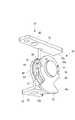
ここで、ヒンジアッセンブリである左側のヒンジピン23aおよび回動制止機構24について、図5、図6および図7を参照して詳細に説明する。回動制止機構24は、一端を上記の左側のヒンジ受け部位37a(装置本体2)に固定した固定片41と、上記の蓋部ケース(上蓋18)34に固定した可動片42と、可動片42を軸方向に付勢する板ばね43と、板ばね43に添設したワッシャ44と、可動片42に添設した位置規制用座金45とで構成されており、これらにヒンジピン23aが挿通している。
【0046】
ヒンジピン23aは、円形の頭部51と、頭部51から延び両側を面取りした胴部52と、胴部52の先端部に位置する段部53とで一体に形成されている。そして、ヒンジピン23aの胴部52には頭部51側から、位置規制用座金45、可動片42、板ばね43、ワッシャ44および固定片41の順で、回動制止機構24の構成部品が重ねるようにして装着され、板ばね43に抗した状態で先端の段部53に固定片41が固着されている。
【0047】
固定片41は、ヒンジピン23aに固着される軸着部61と、ヒンジ受け部位37aにねじ止めされる取付け片部62とを、直角に折り曲げて一体に形成されている。軸着部61の中心位置には、方形の軸着孔63が形成されており、この軸着孔63にヒンジピン23aの段部53が嵌合した状態で固着されている。ワッシャ44は、中心位置にヒンジピン23aの胴部52に対し回止めとなる角孔65を有し、一方の面で固定片41に接触し他方の面で板ばね43に接触している。このワッシャ44により、板ばね43のばね力を周方向において安定させ得るようになっている。
【0048】
板ばね43は、ヒンジピン23aの胴部52に回動自在(回転自在)に挿通する円形孔67を有して環状に形成されていて、その面方向の撓みにより可動片42を軸方向に付勢している。すなわち、可動片42と固定片41との間に板ばね43およびワッシャ44が挟持され、板ばね43により可動片42が軸方向に付勢されることにより、可動片42と板ばね43或いは板ばね43とワッシャ44の間に摩擦力が生じ、可動片42に制動トルクが付与される。これにより、可動片42を介して上蓋18を任意の開放位置(開放角度)に制止させ得るようになっている。
【0049】
可動片42は、ヒンジピン23aの胴部52に回動自在に軸支される略円形の軸支部69と、上記の蓋部ケース34にねじ止めされる取付け片部70とを、直角に折り曲げて一体に形成されている。取付け片部70は、軸支部69との間の曲がり部分から一方向に長方形に延びており、蓋部ケース34のボス部にねじ止めされる。軸支部69の中心位置には円形の軸孔71が形成され、この軸孔71の部分でヒンジピン23aに回動自在に軸支されている。
【0050】
また、軸支部69の周縁部において180°対象位置(2個所)には、後述する位置規制用座金45の係合凸部78,78がクリック係合する切欠き凹部72,72が形成されている。さらに、軸支部69には、その外周部から係方向に突出するように方形の突出片73が延設されており、この突出片73は位置規制用座金45側に折り曲げられている。
【0051】
位置規制座金45は、前記ヒンジピン23aの胴部52に回止め状態で装着した環状の座金本体75と、座金本体75から径方向の外側に延設した略扇形舌片状のストッパ片部76とで、一体に形成されている。座金本体75の中心位置には回止めとなる角孔77が形成され、また周縁部の180°対象位置(2個所)には、上記可動片42の切欠き凹部72,72に係合する係合凸部78,78が形成されている。各係合凸部78は、プレスにより軸方向に打ち出すようにして形成され、その突出形状は周方向において台形形状を為している(図7参照)。
【0052】
一対の切欠き凹部72,72に一対の係合凸部78,78がクリック係合する状態は、可動片42を介して上蓋18が閉塞したときであり、この係合により閉塞した上蓋18が位置規制され、開放方向にわずかに戻ってしまうのを防止している。すなわち、閉塞動作する上蓋18には板ばね43による制動トルクが作用しており、切欠き凹部72と係合凸部78との係合により、閉塞した上蓋18が装置ケース3の上面から浮き上がってしまうのを防止している。また、係合凸部78が台形形状を有しており、その斜面(斜辺)が切欠き凹部72の角部に当接するようにして係合するため、斜面の長さに亘って一定の分力が作用し、上蓋18の閉塞位置の精度が低くても、閉塞した上蓋18を装置ケース3の上面に押し付けておくことができる。
【0053】
ストッパ片部76は、略扇状を為してその両側端(周方向の端)76a,76bが座金本体75の中心から径方向に延在している。そして、図8に示すように、ストッパ片部76の一方の端部76aには、上蓋18が開放端位置に回動(正方向の回動)したときに可動片42の取付け片部70の基端70aが突き当たり、他方の端部76bには、上蓋18が閉塞端位置に回動(逆方向の回動)したときに可動片42の突出片73が突き当たるようになっている。
【0054】
なお、上述したように、閉塞した上蓋18は装置ケース3との間に隙間が生じないように、装置ケース3の上面に押し付けられることになる。このため、実際には、同図(a)に示すように、ストッパ片部76の他方の端部76bと可動片42の突出片73とは、上蓋18が閉塞した状態で1.5°の角度を存して対峙するように設計されている。これにより、回動制止機構24廻りの部品に製造上の誤差や取付け誤差があっても、閉塞した上蓋18と装置ケース2との間に隙間が生じないようになっている。
【0055】
図9に示すように、上蓋18が閉塞した状態では、可動片42はほぼ水平に位置しており、可動片42の切欠き凹部72に位置規制用座金45の係合凸部78がクリック係合すると共に、ストッパ片部76の他方の端部76bと可動片44の突出片73とがわずかな間隙を存して周方向に対峙している(図8(a)参照)。この状態から上蓋18を開放し、液晶ディスプレイ20を斜め後方の起立させた角度で作業を行うが、最大限に開放した開放端位置では、図10に示すように、可動片42は後方斜めに傾いて位置しており、ストッパ片部76の一方の端部76aに可動片42の取付け片部70の基端70aが当接している(図8(a)参照)。したがって、上蓋18を最大限に開放しても、上蓋18の一部が装置ケース3の上面などに突き当たることがなく、装置ケース3を傷つけることがない。
【0056】
このように本実施形態では、上蓋18のヒンジ部32と、開閉蓋6の前部とを前後方向にオーバーラップするように配置しているため、このオーバーラップさせた分、装置本体2の前後方向の寸法を短くすることができる。したがって、カートリッジ収納部7、キーボード17および液晶ディスプレイ20の大きさを犠牲にすることなく、テープ印刷装置1をコンパクトに構成することができる。また、板ばね43により、上蓋18への制動トルクを付与するようにしているため、ヒンジ機構19をコンパクトに構成することができる。
【0057】
なお、ヒンジ機構の回動制止機構は、ヒンジ部の右側に組み込んでもよいし、左右両側に組み込んでもよい。また、ヒンジピンは1本ものを通しで設けるようにしてもよい。さらに、ヒンジ部を右側に寄せて配置したが、カートリッジ収納部の位置などによっては、左側に寄せて配置してもよい。
【0058】
【発明の効果】
以上のように、本発明のテープ印刷装置によれば、上蓋のヒンジ部が、上蓋本体の後端部において左右いずれかの略半部に延設されているため、装置本体の上面中間部の略半部に、適宜部品などを配置することができる。したがって、液晶ディスプレイ付きの上蓋を設けても装置本体を小型化することができる。
【0059】
また、本発明のヒンジ機構によれば、装置本体および上蓋に固定した固定片および可動片と、可動片に付勢しなが摺接する板ばねとを、ヒンジピンの軸方向に並べて配置することができるため、コンパクトに構成することができる。また、板ばねにより、可動片に安定した制動トルクを作用させることができるため、上蓋を無理なく開閉することができると共に、任意の開放角度に適切に制止させることができる。
【図面の簡単な説明】
【図1】本発明の一実施形態に係るテープ印刷装置の外観斜視図である。
【図2】実施形態に係るテープ印刷装置の上蓋を開放した状態の外観斜視図である。
【図3】実施形態に係るテープ印刷装置の開閉蓋を開放した状態の外観斜視図である。
【図4】ヒンジ機構を組み込んだ上蓋を裏面側から見た斜視図である。
【図5】ヒンジ機構の回動制止機構回りの全体斜視図である。
【図6】ヒンジ機構の回動制止機構回りの分解斜視図である。
【図7】ヒンジ機構の回動制止機構回りの側面図である。
【図8】ヒンジ機構の回動状態を示す側面図である。
【図9】上蓋の閉塞状態とヒンジ機構との関係を表したテープ印刷装置の側面図である。
【図10】上蓋の開放状態とヒンジ機構との関係を表したテープ印刷装置の側面図である。
【符号の説明】
1 テープ印刷装置 2 装置本体
3 装置ケース 6 開閉蓋
7 カートリッジ収納部 8 操作ボタン
17 キーボード 18 上蓋
19 ヒンジ機構 20 液晶ディスプレイ
23a ヒンジピン 24 回動制止機構
31 上蓋本体 32 ヒンジ部
41 固定片 42 可動片
43 板ばね 44 ワッシャ
45 位置規制用座金 51 頭部
52 胴部 69 軸支部
70 取付け片部 70a 基端
72 切欠き凹部 73 突出片
75 座金本体 76 ストッパ片部
76a 一方の端部 76b 他方の端部
78 係合凸部[0001]
BACKGROUND OF THE INVENTION
The present invention relates to a tape printing apparatus having an upper lid in which a liquid crystal display is incorporated.In placeIt is related.
[0002]
[Prior art]
2. Description of the Related Art Conventionally, as this type of tape printing apparatus, there has been known one in which a keyboard and an upper lid are disposed in the upper half of the upper surface of the apparatus main body and a tape cartridge housing is disposed in the upper half of the upper surface. In this case, the upper lid is pivotally attached to the apparatus main body via a hinge at the front and rear intermediate portions of the upper surface of the apparatus main body, and is installed inside the keyboard and the upper lid at an open position raised obliquely rearward. The keyboard is covered and the display is closed at the closed position where the keyboard is opened and the front panel is tilted forward. Hinge receiving parts that receive the hinges of the upper lid protrude from the front and rear intermediate parts of the upper surface of the main body of the apparatus, and the hinge parts of the upper lid are fitted between the left and right hinge receiving parts so as to rotate. It is pivotally supported.
[0003]
In addition, this type of upper lid incorporates a hinge mechanism for stopping the upper lid at an arbitrary opening angle so that the standing angle of the display can be adjusted. As such a hinge mechanism, for example, one described in Japanese Patent Application Laid-Open No. 64-78312, is known. This hinge mechanism has a structure in which a hinge pin is wound with a leaf spring, and this structure can arbitrarily adjust the standing angle of the upper lid.
[0004]
[Problems to be solved by the invention]
In such a conventional tape printing apparatus, the hinge part of the upper lid and the hinge receiving part of the apparatus main body are disposed in the front and rear intermediate part of the upper surface of the apparatus main body. A cartridge housing with an open / close lid must be provided on the top. For this reason, the length of the apparatus main body in the front-rear direction becomes a length obtained by adding the keyboard, the hinge part, and the open / close lid (cartridge housing part), and there is a problem that the apparatus becomes large.
In addition, since the conventional hinge mechanism has a structure in which the hinge pin is wound with a leaf spring, the entire mechanism becomes longer in the axial direction, resulting in an increase in size as a whole.
[0005]
The present invention relates to a tape printing apparatus capable of suppressing the enlargement of the apparatus main body even if an upper lid with a display is provided.PlaceThe issue is to provide.
[0006]
[Means for Solving the Problems]
The tape printing apparatus of the present invention includes a keyboard disposed on the upper surface of the apparatus main body, an upper lid that covers the keyboard and incorporates a liquid crystal display inside.An opening / closing lid for closing the tape cartridge housing on the rear upper surface of the apparatus main body, an operation button for opening the opening / closing lid on the upper surface of the apparatus main body,A tape printing apparatus in which the upper lid is attached to the apparatus main body through a hinge mechanism at the rear of the keyboard so as to be openable and closable and can be stopped at an arbitrary opening angle. And has a hinge portion that extends to either the left or right half of the rear end of the upper lid body.The operation button is disposed in the immediate vicinity of the hinge so that it is difficult or impossible to operate when the upper lid is opened.It is characterized by.
[0007]
According to this configuration, the hinge portion of the upper lid incorporating the hinge mechanism is extended to either the left or right substantially half at the rear end portion of the upper lid main body that covers the keyboard. One half becomes empty space. For this reason, it is possible to appropriately arrange components or the like in a substantially half portion of the upper surface intermediate portion of the apparatus main body that becomes this empty space.
Further, when the upper lid is released, it becomes difficult to operate the operation buttons, or it becomes impossible to operate. For this reason, it is possible to effectively prevent an operation button from being accidentally pressed when performing key operations such as input / editing with the upper lid opened, especially when printing is performed based on a print command. Can do.
[0008]
in this caseOpenIt is preferable that the front part of the closing lid and the hinge part are disposed so as to overlap in the front-rear direction.
[0009]
According to this configuration, the front-rear direction of the apparatus main body can be configured to be shorter as the front portion of the opening / closing lid and the hinge portion overlap each other. When performing input / editing operations with the top cover open, the tape cartridge is not attached to or detached from the storage section. Therefore, even if the top cover is opened, the opening / closing cover of the storage section cannot be opened. Will not occur.
[0012]
In these cases, the hinge mechanism has a hinge pin serving as a rotation center of the upper lid that opens and closes, and a rotation stopping mechanism that stops the upper lid at an arbitrary opening angle, and the rotation stopping mechanism includes both left and right ends of the hinge portion. Among these, it is preferable that at least one end portion of the hinge portion which is at a substantially intermediate position between the left and right sides of the upper lid body is incorporated.
[0013]
According to this configuration, the braking torque by the rotation restraining mechanism acts on the upper lid body incorporating the liquid crystal display at a substantially intermediate position between the left and right, so that the braking torque acts on the upper lid body in a well-balanced manner and the upper lid is stabilized. The upper lid body can be prevented from being distorted as much as possible.
[0014]
In the above tape printer, the hinge mechanism isA hinge pin serving as a rotation center of the upper lid that opens and closes, and a rotation stopping mechanism that stops the upper lid at an arbitrary opening angle;HaveThe rotation restraining mechanism includes a fixed piece fixed to one of the apparatus main body and the upper lid and pivotally attached to the hinge pin, a movable piece fixed to the other and pivotally supported by the hinge pin, a sliding piece in contact with the movable piece and the movable piece And an annular leaf spring for urging the shaft in the axial directionIs preferred.
[0015]
According to this configuration, the fixed piece fixed to the apparatus main body (or the upper cover), the movable piece fixed to the upper cover (or the apparatus main body), and the leaf spring that applies a braking torque to the movable piece are arranged in the axial direction of the hinge pin. Since they can be arranged side by side, this portion can be made compact. Further, since the leaf spring is in sliding contact with the movable piece without being biased, the sliding contact area can be made relatively large, and stable braking torque can be applied to the movable piece.
[0016]
In this case, there is a position washer so that the movable piece is sandwiched between the leaf spring and the position restricting washer is an annular washer body that is attached to the hinge pin in a non-rotating state, and a radially outer side from the washer body. And a movable piece having a tongue piece-like stopper portion extending to the first lid piece that contacts one end surface in the circumferential direction of the stopper portion at a positive rotation end position corresponding to the open end position of the upper lid. Is preferably formed.
[0017]
According to this configuration, the movable piece rotates in the forward direction around the hinge pin as the upper lid is opened, and the stopper of the position restricting washer mounted with the first projecting piece of the movable piece being fixed to the hinge pin. The position of the open end position of the upper lid is regulated by coming into contact with one end face of the portion. In this way, by restricting the position of the open end position of the upper lid, for example, the base portion of the upper lid abuts on the upper surface of the apparatus main body (case) when it is fully opened, thereby preventing problems such as damaging it.
[0018]
In this case, the movable piece is composed of a shaft support portion pivotally supported by the hinge pin and an attachment piece fixed to the apparatus main body or the upper lid, and the first projecting piece is one end portion of the attachment piece portion. It is preferable that it is comprised.
[0019]
According to this configuration, the position of the open end position of the upper lid can be regulated using the mounting piece portion of the movable piece without increasing the number of parts.
[0020]
In these cases, it is preferable that the movable piece is formed with a second projecting piece that comes into contact with the other end surface in the circumferential direction of the stopper portion at the reverse rotation end position corresponding to the closed end position of the upper lid.
[0021]
According to this configuration, the movable piece rotates in the reverse direction around the hinge pin as the upper lid is closed, and the second projecting piece of the movable piece comes into contact with the other end surface of the stopper portion of the position regulating washer. Thus, the position of the closed end of the upper lid is regulated. Thus, by restricting the position of the closed end of the upper lid, for example, the upper surface of the apparatus main body (case) can be prevented from receiving an excessive impact when the upper lid is closed.
[0022]
In this case, the movable piece is composed of a shaft support portion pivotally supported by the hinge pin and an attachment piece fixed to the apparatus main body or the upper lid, and the second projecting piece projects in the radial direction of the shaft support portion. It is preferable that the portion is formed by bending the position regulating washer side.
[0023]
According to this configuration, the second protruding piece can be easily formed without increasing the number of parts.
[0024]
In these cases, it is preferable that the second projecting piece is opposed to the other end surface of the stopper portion with a slight gap in a completely closed state where the upper lid falls on the upper surface of the apparatus main body.
[0025]
According to this configuration, a gap is generated between the upper lid of the completely closed state and the upper surface of the apparatus main body (case) based on the molding (processing) accuracy of the upper lid and the assembly accuracy of the hinge mechanism, and the upper lid is lifted. It can be prevented from being blocked in the state. The gap between the second projecting piece and the stopper portion is preferably about 1.5 ° in angle.
[0026]
In these cases, the sliding contact surfaces of the movable piece and the position restricting washer are formed with a concave portion on one side and a convex portion that is click-engaged with the other on the other side. It is preferable to click-engage when rotated to the closed end position.
[0027]
According to this configuration, when the upper lid that is closed while receiving the braking torque by the leaf spring reaches the closed end position, the mutual concave portion and convex portion of the movable piece and the position restricting washer are click-engaged, and thus closed. The upper lid does not return to the opening direction due to the braking torque, and the upper lid can be completely closed so as to contact the upper surface of the apparatus main body (case).
[0028]
In this case, it is preferable that the edge of the concave portion is cut at a right angle, and the convex portion is formed to protrude in a trapezoidal shape.
[0029]
According to this configuration, when the trapezoidal convex portion clicks and engages with the concave portion that falls at a right angle, the convex portion falls from the trapezoidal slope portion into the concave portion. For this reason, the component force based on the angle of the inclined surface acts stably while the inclined surface hits the edge as it falls. That is, the click engagement is stable as compared with a semicircular convex portion and the like, and the displacement between the concave portion and the convex portion can be absorbed.
[0030]
In these cases, the hinge pin is preferably composed of a flange-shaped head and a trunk extending from the head, and is fixed to the fixed piece at the tip of the trunk.
[0031]
According to this configuration, it is possible to easily assemble the fixed piece, the movable piece, the leaf spring, the position restricting washer and the like with respect to the hinge pin, and to assemble these in a compact manner.
[0032]
DETAILED DESCRIPTION OF THE INVENTION
Hereinafter, a tape printer and a hinge mechanism according to an embodiment of the present invention will be described with reference to the accompanying drawings. This tape printer prints a desired character or figure on a printing tape with peeling, and cuts a printed portion of the printing tape into a predetermined length to create a label.
[0033]
1 is an overall perspective view of the tape printing apparatus, FIG. 2 is an overall perspective view of the tape printing apparatus with an upper lid opened, and FIG. 3 is an overall perspective view of the tape printing apparatus with an openable lid opened. As shown in these drawings, the
[0034]
A molding / cutting mechanism (not shown) for trimming the corners of the
[0035]
Although not shown, a tape discharge port for feeding out the printed
[0036]
A crescent-shaped
[0037]
The apparatus
[0038]
In the
[0039]
Next, the
[0040]
On the other hand, when trimming the printed portion of the
[0041]
As shown in FIGS. 1 and 2, the
[0042]
That is, the
[0043]
In this case, since the
[0044]
Next, the
[0045]
Here, the
[0046]
The
[0047]
The fixing
[0048]
The
[0049]
The
[0050]
Further, at the 180 ° target position (two locations) at the peripheral portion of the
[0051]
The
[0052]
The state in which the pair of engaging
[0053]
The
[0054]
As described above, the closed
[0055]
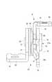
As shown in FIG. 9, when the
[0056]
As described above, in this embodiment, the
[0057]
In addition, the rotation stopping mechanism of the hinge mechanism may be incorporated on the right side of the hinge portion or on both the left and right sides. Moreover, you may make it provide a hinge pin through one thing. Further, although the hinge portion is arranged close to the right side, the hinge portion may be arranged close to the left side depending on the position of the cartridge storage portion.
[0058]
【The invention's effect】
As described above, according to the tape printer of the present invention, the hinge portion of the upper lid is extended to either the left or right substantially half at the rear end portion of the upper lid main body. Parts or the like can be appropriately arranged in the substantially half portion. Therefore, even if an upper lid with a liquid crystal display is provided, the apparatus main body can be reduced in size.
[0059]
Further, according to the hinge mechanism of the present invention, the fixed piece and the movable piece fixed to the apparatus main body and the upper lid, and the leaf spring that is slidably contacted with the movable piece while being arranged in the axial direction of the hinge pin can be arranged. Therefore, it can be configured compactly. In addition, since a stable braking torque can be applied to the movable piece by the leaf spring, the upper lid can be opened and closed without difficulty and can be appropriately stopped at an arbitrary opening angle.
[Brief description of the drawings]
FIG. 1 is an external perspective view of a tape printer according to an embodiment of the present invention.
FIG. 2 is an external perspective view in a state where an upper lid of the tape printer according to the embodiment is opened.
FIG. 3 is an external perspective view of the tape printer according to the embodiment in a state where an opening / closing lid is opened.
FIG. 4 is a perspective view of an upper lid incorporating a hinge mechanism as viewed from the back side.
FIG. 5 is an overall perspective view around the rotation stopping mechanism of the hinge mechanism.
FIG. 6 is an exploded perspective view around the rotation stopping mechanism of the hinge mechanism.
FIG. 7 is a side view around the rotation stopping mechanism of the hinge mechanism.
FIG. 8 is a side view showing a rotating state of the hinge mechanism.
FIG. 9 is a side view of the tape printer showing the relationship between the closed state of the upper lid and the hinge mechanism.
FIG. 10 is a side view of the tape printer showing the relationship between the open state of the upper lid and the hinge mechanism.
[Explanation of symbols]
1
3
7
17
19
31
41 fixed
43
45
52
70
72
75
76a One
78 engaging projection
Claims (12)
Translated fromJapanese前記上蓋は、前記キーボードを覆う上蓋本体と、
前記ヒンジ機構を内蔵すると共に、前記上蓋本体の後端部において左右いずれかの略半部に延設したヒンジ部とを有し、
前記操作ボタンは、前記上蓋を開放したときに操作し難い或いは操作不能となるように、前記ヒンジ部の後方直近に配設されていることを特徴とするテープ印刷装置。A keyboard disposed on the upper surface of the apparatus main body, an upper lid that covers the keyboard and incorporates a liquid crystal display inside;an opening / closing lid that closes a tape cartridge housing portion on the rear upper surface of the apparatus main body; An operation button for opening the opening / closing lid on the upper surface, and the upper lid is attached to the apparatus main body via a hinge mechanism at the rear of the keyboard so as to be openable and closable at an arbitrary opening angle. In the printing device,
The upper lid includes an upper lid body that covers the keyboard;
The hinge mechanism is built-in, and has a hinge portion that extends to either the left or right substantially half at the rear end of the upper lid body,
The tape printing apparatus according toclaim 1, wherein the operation button is disposed immediately behind the hinge portion so that the operation button is difficult to operate or cannot be operated when the upper lid is opened .
前記回動制止機構は、前記ヒンジ部の左右両端部のうち、少なくとも前記上蓋本体の左右略中間位置となる前記ヒンジ部の一方の端部に組み込まれていることを特徴とする請求項1または2に記載のテープ印刷装置。The hinge mechanism has a hinge pin serving as a rotation center of the upper lid that opens and closes, and a rotation stopping mechanism that stops the upper lid at an arbitrary opening angle,
The rotation stop feature of the left and right ends of the hinge portion, or claim1, characterized in that built into one end of at least the left and right substantially middle position of the upper lid body said hinge portion The tape printer according to2.
前記回動制止機構は、前記装置本体および前記上蓋の一方に固定され且つ前記ヒンジピンに軸着する固定片および他方に固定され前記ヒンジピンに回動自在に軸支される可動片と、
前記可動片に摺接すると共に当該可動片を軸方向に付勢する環状の板ばねとを有することを特徴とする請求項1または2に記載のテープ印刷装置。The hinge mechanism has a hinge pin serving as a rotation center of the upper lidthat opensand closes, and a rotation stopping mechanism that stops the upper lid at an arbitrary opening angle,
The rotation stopping mechanism is fixed to one of the apparatus main body and the upper lid and fixed to the hinge pin, and a movable piece fixed to the other and pivotally supported by the hinge pin;
The tape printing apparatus according toclaim 1, further comprising an annular leaf spring that slidably contacts the movable piece and urges the movable piece in an axial direction.
前記位置規制用座金は、前記ヒンジピンに回止め状態で装着した環状の座金本体と、前記座金本体から径方向の外側に延設した舌片状のストッパ部とから成り、
前記可動片には、前記上蓋の開放端位置に対応する正方向回動端位置で前記ストッパ部の周方向の一方の端面に当接する第1突片が形成されていることを特徴とする請求項4に記載のテープ印刷装置。A position restricting washer so as to sandwich the movable piece between the leaf spring and the leaf spring;
The position restricting washer is composed of an annular washer body mounted in a locked state on the hinge pin, and a tongue-like stopper portion extending radially outward from the washer body,
The movable piece is formed with a first projecting piece that comes into contact with one end surface in the circumferential direction of the stopper portion at a forward rotation end position corresponding to an open end position of the upper lid. Item 5. Thetape printer according to item4.
前記第1突片は、前記取付け片部の一方の端部で構成されていることを特徴とする請求項5に記載のテープ印刷装置。The movable piece is composed of a shaft support portion pivotally supported by the hinge pin and an attachment piece fixed to the apparatus main body or the upper lid,
Thetape printing apparatus according to claim5 , wherein the first projecting piece is configured by one end of the attachment piece.
前記第2突片は、前記軸支部の径方向に突出する部位を前記位置規制用座金側に折り曲げて形成されていることを特徴とする請求項7に記載のテープ印刷装置。The movable piece is composed of a shaft support portion pivotally supported by the hinge pin and an attachment piece fixed to the apparatus main body or the upper lid,
Thetape printing apparatus according to claim7 , wherein the second projecting piece is formed by bending a portion projecting in a radial direction of the shaft support portion toward the position restricting washer.
前記凹部と前記凸部とは、前記上蓋が閉塞端位置に回動したときにクリック係合することを特徴とする請求項5ないし9のいずれかに記載のテープ印刷装置。On the sliding contact surfaces of the movable piece and the position regulating washer, a concave portion is formed on one side, and a convex portion that click-engages with the other is formed on the other side,
Wherein the concave portion and the convex portion,the tape printing apparatus according to any one of the upper lid claims5, characterized in that clicking engagement when rotated to the closed end position9.
前記凸部は台形形状に突出形成されていることを特徴とする請求項10に記載のテープ印刷装置。The recess is cut at a right angle at its edge,
Thetape printing apparatus according to claim10 , wherein the convex portion is formed to protrude in a trapezoidal shape.
前記胴部の先端部で前記固定片に固着していることを特徴とする請求項4ないし11のいずれかに記載のテープ印刷装置。The hinge pin comprises a flange-shaped head and a trunk extending from the head,
Thetape printing apparatus according to any one of claims4 to11 , wherein thetape printing apparatus is fixed to the fixed piece at a front end portion of the body portion.
Priority Applications (1)
| Application Number | Priority Date | Filing Date | Title |
|---|---|---|---|
| JP2000358176AJP4501273B2 (en) | 2000-11-24 | 2000-11-24 | Tape printer |
Applications Claiming Priority (1)
| Application Number | Priority Date | Filing Date | Title |
|---|---|---|---|
| JP2000358176AJP4501273B2 (en) | 2000-11-24 | 2000-11-24 | Tape printer |
Publications (2)
| Publication Number | Publication Date |
|---|---|
| JP2002160421A JP2002160421A (en) | 2002-06-04 |
| JP4501273B2true JP4501273B2 (en) | 2010-07-14 |
Family
ID=18830126
Family Applications (1)
| Application Number | Title | Priority Date | Filing Date |
|---|---|---|---|
| JP2000358176AExpired - Fee RelatedJP4501273B2 (en) | 2000-11-24 | 2000-11-24 | Tape printer |
Country Status (1)
| Country | Link |
|---|---|
| JP (1) | JP4501273B2 (en) |
Families Citing this family (4)
| Publication number | Priority date | Publication date | Assignee | Title |
|---|---|---|---|---|
| JP4569517B2 (en)* | 2006-05-15 | 2010-10-27 | 村田機械株式会社 | Image forming apparatus |
| JP2011029815A (en) | 2009-07-23 | 2011-02-10 | Seiko Epson Corp | Tilt panel apparatus and electronic device |
| JP6834145B2 (en)* | 2016-03-01 | 2021-02-24 | 富士ゼロックス株式会社 | Image forming device |
| JP7043309B2 (en)* | 2018-03-23 | 2022-03-29 | サトーホールディングス株式会社 | Printer |
Family Cites Families (6)
| Publication number | Priority date | Publication date | Assignee | Title |
|---|---|---|---|---|
| US5022771A (en)* | 1989-07-17 | 1991-06-11 | Kroy Inc. | Thermal printing apparatus and tape supply cartridge therefor |
| JP2589479Y2 (en)* | 1991-08-30 | 1999-01-27 | 加藤電機株式会社 | Tilt hinge for OA equipment |
| JP2601301Y2 (en)* | 1992-06-24 | 1999-11-15 | カシオ計算機株式会社 | Electronics |
| JP2702470B2 (en)* | 1996-01-26 | 1998-01-21 | 埼玉日本電気株式会社 | Hinge structure of foldable equipment |
| JPH10173747A (en)* | 1996-12-05 | 1998-06-26 | Saitama Nippon Denki Kk | Hinge switching/closing structure for folding equipment |
| JP3693777B2 (en)* | 1997-01-30 | 2005-09-07 | 富士写真フイルム株式会社 | Image recording device |
- 2000
- 2000-11-24JPJP2000358176Apatent/JP4501273B2/ennot_activeExpired - Fee Related
Also Published As
| Publication number | Publication date |
|---|---|
| JP2002160421A (en) | 2002-06-04 |
Similar Documents
| Publication | Publication Date | Title |
|---|---|---|
| US5839840A (en) | Tape printing apparatus | |
| US6563699B1 (en) | Portable computer having locking apparatus | |
| JP4075325B2 (en) | Tape cutting mechanism of tape printer | |
| JP4667725B2 (en) | Portable information processing device | |
| WO2015146795A1 (en) | Tape cartridge | |
| JP4501273B2 (en) | Tape printer | |
| JPH09297983A (en) | Door opening and closing mechanism for recording and reproducing device | |
| JP6100721B2 (en) | Tape cartridge | |
| JPH11245476A (en) | Printer | |
| JP3943412B2 (en) | Tape printer tape cutting device and tape printer having the same | |
| JP6459602B2 (en) | Tape printer and tape printing system | |
| JP5200804B2 (en) | Printing device | |
| WO2015146093A1 (en) | Tape printing device and tape printing system | |
| US7484778B2 (en) | Portable computer having improved latch mechanism | |
| US20070070432A1 (en) | Printer | |
| JP3886692B2 (en) | Pop-up key | |
| WO2016147542A1 (en) | Tape printer | |
| JP6347173B2 (en) | Tape printer and tape printing system | |
| JP2003237177A (en) | Tape printer | |
| JP3738581B2 (en) | Tape printer | |
| JP4846695B2 (en) | Throttle adjustment mechanism with cell start switch | |
| JP2010036439A (en) | Turning regulating device and recording device | |
| JPH05147285A (en) | Printer | |
| JP4003772B2 (en) | Tape printer | |
| JP3341599B2 (en) | LCD protective cover structure for portable information terminals |
Legal Events
| Date | Code | Title | Description |
|---|---|---|---|
| A621 | Written request for application examination | Free format text:JAPANESE INTERMEDIATE CODE: A621 Effective date:20061215 | |
| A711 | Notification of change in applicant | Free format text:JAPANESE INTERMEDIATE CODE: A711 Effective date:20061215 | |
| A521 | Request for written amendment filed | Free format text:JAPANESE INTERMEDIATE CODE: A821 Effective date:20061215 | |
| A131 | Notification of reasons for refusal | Free format text:JAPANESE INTERMEDIATE CODE: A131 Effective date:20091110 | |
| A521 | Request for written amendment filed | Free format text:JAPANESE INTERMEDIATE CODE: A523 Effective date:20091228 | |
| TRDD | Decision of grant or rejection written | ||
| A01 | Written decision to grant a patent or to grant a registration (utility model) | Free format text:JAPANESE INTERMEDIATE CODE: A01 Effective date:20100330 | |
| A01 | Written decision to grant a patent or to grant a registration (utility model) | Free format text:JAPANESE INTERMEDIATE CODE: A01 | |
| A61 | First payment of annual fees (during grant procedure) | Free format text:JAPANESE INTERMEDIATE CODE: A61 Effective date:20100412 | |
| R150 | Certificate of patent or registration of utility model | Free format text:JAPANESE INTERMEDIATE CODE: R150 | |
| FPAY | Renewal fee payment (event date is renewal date of database) | Free format text:PAYMENT UNTIL: 20130430 Year of fee payment:3 | |
| FPAY | Renewal fee payment (event date is renewal date of database) | Free format text:PAYMENT UNTIL: 20130430 Year of fee payment:3 | |
| FPAY | Renewal fee payment (event date is renewal date of database) | Free format text:PAYMENT UNTIL: 20140430 Year of fee payment:4 | |
| S531 | Written request for registration of change of domicile | Free format text:JAPANESE INTERMEDIATE CODE: R313531 | |
| R350 | Written notification of registration of transfer | Free format text:JAPANESE INTERMEDIATE CODE: R350 | |
| LAPS | Cancellation because of no payment of annual fees |