JP4500485B2 - Display device with touch panel - Google Patents
Display device with touch panelDownload PDFInfo
- Publication number
- JP4500485B2 JP4500485B2JP2002249192AJP2002249192AJP4500485B2JP 4500485 B2JP4500485 B2JP 4500485B2JP 2002249192 AJP2002249192 AJP 2002249192AJP 2002249192 AJP2002249192 AJP 2002249192AJP 4500485 B2JP4500485 B2JP 4500485B2
- Authority
- JP
- Japan
- Prior art keywords
- touch
- display screen
- screen
- displayed
- fingertip
- Prior art date
- Legal status (The legal status is an assumption and is not a legal conclusion. Google has not performed a legal analysis and makes no representation as to the accuracy of the status listed.)
- Expired - Lifetime
Links
Images


Classifications
- G—PHYSICS
- G06—COMPUTING OR CALCULATING; COUNTING
- G06F—ELECTRIC DIGITAL DATA PROCESSING
- G06F3/00—Input arrangements for transferring data to be processed into a form capable of being handled by the computer; Output arrangements for transferring data from processing unit to output unit, e.g. interface arrangements
- G06F3/01—Input arrangements or combined input and output arrangements for interaction between user and computer
- G06F3/016—Input arrangements with force or tactile feedback as computer generated output to the user
- F—MECHANICAL ENGINEERING; LIGHTING; HEATING; WEAPONS; BLASTING
- F16—ENGINEERING ELEMENTS AND UNITS; GENERAL MEASURES FOR PRODUCING AND MAINTAINING EFFECTIVE FUNCTIONING OF MACHINES OR INSTALLATIONS; THERMAL INSULATION IN GENERAL
- F16M—FRAMES, CASINGS OR BEDS OF ENGINES, MACHINES OR APPARATUS, NOT SPECIFIC TO ENGINES, MACHINES OR APPARATUS PROVIDED FOR ELSEWHERE; STANDS; SUPPORTS
- F16M11/00—Stands or trestles as supports for apparatus or articles placed thereon ; Stands for scientific apparatus such as gravitational force meters
- F16M11/02—Heads
- F16M11/04—Means for attachment of apparatus; Means allowing adjustment of the apparatus relatively to the stand
- F16M11/06—Means for attachment of apparatus; Means allowing adjustment of the apparatus relatively to the stand allowing pivoting
- F16M11/10—Means for attachment of apparatus; Means allowing adjustment of the apparatus relatively to the stand allowing pivoting around a horizontal axis
- F—MECHANICAL ENGINEERING; LIGHTING; HEATING; WEAPONS; BLASTING
- F16—ENGINEERING ELEMENTS AND UNITS; GENERAL MEASURES FOR PRODUCING AND MAINTAINING EFFECTIVE FUNCTIONING OF MACHINES OR INSTALLATIONS; THERMAL INSULATION IN GENERAL
- F16M—FRAMES, CASINGS OR BEDS OF ENGINES, MACHINES OR APPARATUS, NOT SPECIFIC TO ENGINES, MACHINES OR APPARATUS PROVIDED FOR ELSEWHERE; STANDS; SUPPORTS
- F16M11/00—Stands or trestles as supports for apparatus or articles placed thereon ; Stands for scientific apparatus such as gravitational force meters
- F16M11/02—Heads
- F16M11/18—Heads with mechanism for moving the apparatus relatively to the stand
- G—PHYSICS
- G06—COMPUTING OR CALCULATING; COUNTING
- G06F—ELECTRIC DIGITAL DATA PROCESSING
- G06F1/00—Details not covered by groups G06F3/00 - G06F13/00 and G06F21/00
- G06F1/16—Constructional details or arrangements
- G06F1/1601—Constructional details related to the housing of computer displays, e.g. of CRT monitors, of flat displays
- G—PHYSICS
- G06—COMPUTING OR CALCULATING; COUNTING
- G06F—ELECTRIC DIGITAL DATA PROCESSING
- G06F3/00—Input arrangements for transferring data to be processed into a form capable of being handled by the computer; Output arrangements for transferring data from processing unit to output unit, e.g. interface arrangements
- G06F3/01—Input arrangements or combined input and output arrangements for interaction between user and computer
- G06F3/03—Arrangements for converting the position or the displacement of a member into a coded form
- G06F3/041—Digitisers, e.g. for touch screens or touch pads, characterised by the transducing means
- G06F3/0416—Control or interface arrangements specially adapted for digitisers
- G06F3/0418—Control or interface arrangements specially adapted for digitisers for error correction or compensation, e.g. based on parallax, calibration or alignment
- G—PHYSICS
- G06—COMPUTING OR CALCULATING; COUNTING
- G06F—ELECTRIC DIGITAL DATA PROCESSING
- G06F3/00—Input arrangements for transferring data to be processed into a form capable of being handled by the computer; Output arrangements for transferring data from processing unit to output unit, e.g. interface arrangements
- G06F3/01—Input arrangements or combined input and output arrangements for interaction between user and computer
- G06F3/048—Interaction techniques based on graphical user interfaces [GUI]
- G06F3/0487—Interaction techniques based on graphical user interfaces [GUI] using specific features provided by the input device, e.g. functions controlled by the rotation of a mouse with dual sensing arrangements, or of the nature of the input device, e.g. tap gestures based on pressure sensed by a digitiser
- G06F3/0488—Interaction techniques based on graphical user interfaces [GUI] using specific features provided by the input device, e.g. functions controlled by the rotation of a mouse with dual sensing arrangements, or of the nature of the input device, e.g. tap gestures based on pressure sensed by a digitiser using a touch-screen or digitiser, e.g. input of commands through traced gestures
- G06F3/04883—Interaction techniques based on graphical user interfaces [GUI] using specific features provided by the input device, e.g. functions controlled by the rotation of a mouse with dual sensing arrangements, or of the nature of the input device, e.g. tap gestures based on pressure sensed by a digitiser using a touch-screen or digitiser, e.g. input of commands through traced gestures for inputting data by handwriting, e.g. gesture or text
- G—PHYSICS
- G07—CHECKING-DEVICES
- G07F—COIN-FREED OR LIKE APPARATUS
- G07F19/00—Complete banking systems; Coded card-freed arrangements adapted for dispensing or receiving monies or the like and posting such transactions to existing accounts, e.g. automatic teller machines
- G07F19/20—Automatic teller machines [ATMs]
- G07F19/205—Housing aspects of ATMs
- F—MECHANICAL ENGINEERING; LIGHTING; HEATING; WEAPONS; BLASTING
- F16—ENGINEERING ELEMENTS AND UNITS; GENERAL MEASURES FOR PRODUCING AND MAINTAINING EFFECTIVE FUNCTIONING OF MACHINES OR INSTALLATIONS; THERMAL INSULATION IN GENERAL
- F16M—FRAMES, CASINGS OR BEDS OF ENGINES, MACHINES OR APPARATUS, NOT SPECIFIC TO ENGINES, MACHINES OR APPARATUS PROVIDED FOR ELSEWHERE; STANDS; SUPPORTS
- F16M2200/00—Details of stands or supports
- F16M2200/02—Locking means
- F16M2200/021—Locking means for rotational movement
- F16M2200/024—Locking means for rotational movement by positive interaction, e.g. male-female connections
Landscapes
- Engineering & Computer Science (AREA)
- General Engineering & Computer Science (AREA)
- Theoretical Computer Science (AREA)
- Physics & Mathematics (AREA)
- General Physics & Mathematics (AREA)
- Human Computer Interaction (AREA)
- Accounting & Taxation (AREA)
- Mechanical Engineering (AREA)
- Business, Economics & Management (AREA)
- Finance (AREA)
- Computer Hardware Design (AREA)
- Position Input By Displaying (AREA)
- User Interface Of Digital Computer (AREA)
- Devices For Indicating Variable Information By Combining Individual Elements (AREA)
Description
Translated fromJapanese【0001】
【発明の属する技術分野】
本発明は、据置型や携帯型などの端末装置に用いられるタッチパネルを備えた表示装置に関する。
【0002】
【従来の技術】
近年、各種業界では、端末装置が広く使用されるようになってきている。例えば、銀行などでATM(Automatic Tellers Machine:自動預入支払機)が、駅などでは券売機や地図案内機が夫々設置され、銀行や駅などの業務の一部を端末装置で賄うことができるようにしている。また、ファーストフード店などの店舗においても、商品の注文処理に端末装置を用いるようにする場合もあり(例えば、特開平5ー216587号公報)、さらに、インターネットなどの通信ネットワークを利用してコンテンツの配信を受ける端末装置やウェブ閲覧(ブラウズ)用の端末装置なども実現あるいは提案されている。
【0003】
ところで、このような端末装置では、表示装置が設けられており、その表示画面に表示されるメッセージなどの情報を見ながらキーボードなどの入力手段を操作することにより、上記のような各種の作業ができるようにしているが、表示画面に入力手段としての機能を持たせ、その表示画面に表示されるメッセージやメニューなどにしたがって画面操作を行なうことにより、各種の作業を実行することができるようにしたタッチパネルを備えた表示装置が用いられるようになってきている。
【0004】
このようなタッチパネルを備えた表示装置によると、その表示画面に直接指先を触れて操作を行なうものであるから、操作がし易く、操作の間違いが少ない、という優れた操作性を実現することができるし、また、キーボードなどの操作部も、操作ボタンの数を少なくすることができるので、端末装置自体を小型化でき、設置面積も狭くできて、店内や構内などでの設置場所の自由度が高まるといったようなメリットも得られることになる。
【0005】
【発明が解決しようとする課題】
しかし、従来のタッチパネルを備えた表示装置では、その表示画面に操作ボタン(タッチボタン)などのタッチ操作部材からなる入力手段の画像を表示することにより、その入力手段を顧客やユーザの視覚で認識させ、この認識のもとに、この入力手段の画像の操作したいと思われる個所をタッチして操作するものであるから、次のような問題が生ずる。
【0006】
まず、ユーザがタッチ操作するためのタッチ操作部材のタッチ操作エリアは、表示画面に表示されたものであるから、そのタッチ操作エリア以外の部分と同じ平面上にあり、キーボードなどの操作部とは違って、タッチ操作エリアをタッチした感じとそれ以外の部分をタッチした感じとは同じである。このため、指先でタッチした位置が所望とするタッチ操作エリアからずれても、気が付かない場合もあり得る。
【0007】
特に、タッチ操作部材として、案内のメッセージなどとともに、いくつかの操作ボタンを表示する場合には、これら操作ボタンを表示画面のあちこちに表示する場合があり、このように表示される操作ボタンを操作する場合には、指先のタッチ位置が所望とする操作ボタンの表示位置からずれる場合もあり得る。このようなずれがわずかであっても、この操作ボタンはタッチされなかったことになり、機能しない。しかし、ユーザとしては、その操作ボタンにタッチしたつもりであり、タッチしていないことに気が付かない場合もある。このため、再度同じ操作スイッチをタッチする操作をすることになるが、このためには、タッチしなかったと認識することが必要であり、しかし、この認識にある程度の時間を要することになる、という問題があった。
【0008】
また、多くの操作ボタンが互いに近接して表示画面に同時に表示するような場合もあり、このような場合には、各操作ボタンは比較的小さく表示されるので、指先のタッチ位置が所望とする操作ボタンの表示位置からわずかでもずれると、隣の操作ボタンにタッチしてしまうこともある。従来のタッパネルを備えた表示装置は、表示される操作ボタンがタッチされると、直ちに機能するように構成されているので、タッチ位置がずれて隣の操作ボタンにタッチすると、この隣の操作ボタンが機能してしまい、この機能を停止させて再度操作をし直さなければならない、という問題があった。
【0009】
本発明の目的は、かかる問題を解消し、表示画面に表される操作ボタンなどのタッチ操作部材を指先などでタッチしたことを容易に認識でき、しかも、該タッチ操作部材を操作したことを容易にかつ確実に認識できるようにしたタッチパネルを備えた表示装置を提供することにある。
【0010】
【課題を解決するための手段】
上記目的を達成するために、本発明は、表示パネルの表示画面に指示手段のタッチ位置を検出するタッチパネルが設けられ、表示画面に表示されるタッチ操作部材をタッチして操作できるようにしたタッチパネルを備えた表示装置であって、タッチ操作部材をタッチ操作する際の指示手段による押圧力Pを検知する検知手段と、予め設定圧力P1,P2(但し、P1<P2)が設けられ、検知手段による検知圧力PがP1≦P<P2であるとき、指示手段によって押圧されたタッチ操作部材に関する第1の処理を行ない、押圧力PがP1≦P<P2からP2≦Pに変化したとき、指示手段によって押圧されたタッチ操作部材に関する第2の処理を行なう制御部とを有し、第1の処理は、表示画面に表示された操作ボタンの選択処理であって、かつ、表示画面を指示手段による押圧方向に移動させ、その移動量が押圧力Pの増加に応じて連続的に変化する処理であって、押圧力PがP1≦P<P2からタッチ操作部材が押し込められたとするP2≦Pに変化したとき、選択処理された操作ボタンの決定処理が行なわれ、かつ、第2の処理により、表示画面を指示手段による押圧方向にさらに移動させる機能を実行させ、第2の処理における押圧力の増加に対する移動量の変化の割合が、第1の処理における押圧力の増加に対する移動量の変化の割合よりも大きいものとするものである。
【0011】
また、本発明は、表示パネルの表示画面に指示手段のタッチ位置を検出するタッチパネルが設けられ、表示画面に表示されるタッチ操作部材をタッチして操作できるようにしたタッチパネルを備えた表示装置であって、タッチ操作部材をタッチ操作する際の指示手段による押圧力Pを検知する検知手段と、予め設定圧力P1,P2(但し、P1<P2)が設けられ、検知手段による検知圧力PがP1≦P<P2であるとき、指示手段によって押圧されたタッチ操作部材に関する第1の処理を行ない、押圧力PがP1≦P<P2からP2≦Pに変化したとき、指示手段によって押圧されたタッチ操作部材に関する第2の処理を行なう制御部とを有し、表示画面に表示された操作ボタンの選択処理である第1の処理により、表示画面を指示手段による押圧方向に移動させる機能を実行させ、押圧力PがP1≦P<P2からタッチ操作部材が押し込められたとするP2≦Pに変化したとき、選択処理がなされた操作ボタンの決定処理である第2の処理により、表示画面を指示手段による押圧方向とは逆の向きに移動させる機能を実行させるものである。
【0012】
そして、さらに、表示画面を駆動するための駆動モータを有し、検知手段によって検知された押圧力Pに応じて、制御手段が該駆動モータを駆動し、第1の処理及び第2の処理における表示画面の移動が該駆動モータによって行なわれるものである。
【0013】
また、タッチパネルには、複数のタッチ操作部材が表示されるものであり、タッチ操作部材の種類によって設定圧力P2が異なるものである。
【0015】
【発明の実施の形態】
以下、本発明の実施形態を図面を用いて説明する。
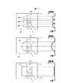
図1は本発明によるタッチパネルを備えた表示装置の第1の実施形態を示す構成図であって、同図(a)は外観斜視図、同図(b)は側面図、同図(c)は断面図であり、1は筐体、1aは開口、2は表示画面、3は取付部、4はスタンド、5は回転軸、6はピン穴、7はピン、8は表示パネル、8aは表示面、9はタッチパネル、10,10a,10bは支持部材、11は駆動モータ、12は回転歯車、13は平歯車、14はリンク機構、14a,14bはリンク、14c,14dは支持部材、15,16は引張りバネである。
【0016】
同図において、箱型の筐体1の前面に矩形状の開口1aが形成されており、この開口1aに表示画面2が設けられている。この表示画面2に、図示しないが、操作ボタンやメッセージなどのタッチ操作できる部材(以下、タッチ操作部材という)が表示され、かかるタッチ操作部材をタッチ操作することにより、この実施形態である表示装置を利用した装置(例えば、後述するATMや券売機など)を動作させることができる。
【0017】
この筐体1の開口1aとは反対側の背面側には、取付部3が一体に設けられており、この取付部3が回転軸5を介してスタンド4に取り付けられている。この取付部3は、従って、筐体1は、スタンド4に対して、この回転軸5を中心に回動可能であり、筐体1をこのように回動させることにより、表示画面2の上下方向の向きを変えることができる。
【0018】
表示画面2の向きを連続的に変えることができるようにしてもよいが、ここでは、段階的に変化できるようにしている。このために、図1(b)に示すように、取付部3の側面部に、回転軸5を中心として複数のピン穴6が設けられており、これらピン穴6の配列線上の一点に対向して、このピン穴6に嵌り込むピン7がスタンド4に押し込み可能に設けられている。筐体1を回転軸5を中心に回動させ、表示画面2を所定の向きにすると、ピン7がこれに近いピン穴6に嵌め込むことができ、表示画面2はほぼこの所定の向きで安定化する。
【0019】
このように、ピン穴6とピン7とは、表示画面の向き(角度)を調整する手段を構成しており、ピン穴6の個数分だけ、表示画面2の向きを変えることができる。
【0020】
この筐体1内では、図1(c)に示すように、表示手段を形成する表示パネル8とタッチパネル9とからなる表示手段が内蔵されており、この表示パネル8の表示面8aとタッチパネル9とで表示画面2を形成している。タッチパネル9は、この表示部8aに対向し、その周辺部が支持部材10によって表示パネル8で支持されている。
【0021】
筐体1内には、また、表示画面2を筐体1の開口1aに対して前後に移動させるための移動機構を備え、タッチパネル9での指先などによる押圧力に応じて表示画面2を開口1aから引っ込めることができるようにしている。
【0022】
この移動機構は、図1(c)において、駆動モータ11やリンク機構14などを用いて構成され、筐体1内の表示パネル8よりも奥部に配置されている。
【0023】
この移動機構の一具体的な構成例としては、駆動モータ11の回転軸に回転歯車12が固定されており、この回転歯車に平歯車13が噛合している。この平歯車13の一方の端部にリンク機構14が取り付けられている。このリンク機構14は、互いにほぼ反対方向に配置されて夫々の一端が平歯車13に回動可能に取り付けられた2つのリンク14a,14bと、リンク14aのほぼ中央部を支持する支持部材14cと、リンク14bのほぼ中央部と回動可能にリンクしてこのリンク14bを支持する支持部材14dとからなり、リンク14aの他端で表示パネル8の一方側の支持部材10aを支持し、リンク14bの他端が表示パネル8の他方側の支持部材10bと回動可能にリンクしている。
【0024】
また、平歯車13の他端は、引張りバネ15により、図面上回転歯車12を中心として反時計廻り方向に引っ張られており、これにより、平歯車13は回転歯車12に押し付けられている。さらに、リンク機構14を常に良好なバランス状態に維持するための引張りバネ16も設けられている。
【0025】
表示パネル8とタッチパネル9とからなる表示手段は、かかるリンク機構14により、タツチパネル9が筐体1の開口1aの近傍に位置するように、支持されている。
【0026】
図2は上記移動機構の動作を示す図であり、図1に対応する部分には同一符号をつけている。
【0027】
図2(a)は表示画面2の初期状態を示すものであって、平歯車13が最も奥側に移動した状態、即ち、平歯車13が、そのリンク14a,14b側の端部で回転歯車12と噛み合った状態にある。この状態では、リンク14a,14bの平歯車13側端部がこの平歯車13によって引っ張られ、リンク14aは支持部材14cを中心に時計廻り方向に、また、リンク14bは支持部材14dを中心に反時計廻り方向に夫々回動した状態にあり、これにより、これらリンク14a,14bによって支持部材10a,10bが持ち上げられて表示画面のタッチパネル9が開口1aに当接もしくは開口1aに近接して配置されている。
【0028】
駆動モータ11が時計廻り方向に所定回転量だけ回転すると、図2(b)に示すように、平歯車13が表示パネル8側に移動し、リンク14a,14bの端部がこの平歯車13によって表示パネル8側に押される。この結果、リンク14aは支持部材14cを中心に反時計廻り方向に、また、リンク14bは支持部材14dを中心に時計廻り方向に夫々回動し、表示パネル8は矢印A方向に移動し、表示画面2が開口1aから後退する(引き込む)ことになる。
【0029】
駆動モータ11が時計廻り方向に最大限回転したときには、図2(c)に示すように、平歯車13がその引張りバネ15側の端部で回転歯車12と噛み合う状態となる。この状態では、リンク14a,14bが上記の方向に最大限回動し、この結果、表示パネル8は矢印A方向に最大限移動したことになり、表示画面2が開口1aから最大限引っ込んだ状態となる。
【0030】
図2(b),(c)に示す状態から駆動モータ11が反時計廻り方向に回転すると、最終的には、図2(a)に示す初期状態に戻る。ここで、駆動モータ11は角度センサを備えており、常に自身の回転角を検知してその回転角を制御することができるようにしている。
【0031】
なお、ここでは、リンク機構14の駆動手段として、歯車機構を用いたが、カムなどの他の機構を用いるようにしてもよい。
【0032】
図3は図1における筐体1内の移動機構を有する表示手段の他の具体例を概略的に示す断面図である。そして、図3(a)は表示装置を移動させず、タッチパネル部のみを移動可能としたものであり、表示装置8はブラウン管,液晶パネルあるいはプラズマ表示パネルである。また、図3(b)は液晶プロジェクタなどのプロジェクタの場合であり、表示パネル8として液晶パネルやブラウン管などの場合である。ここで、17は映出装置、18はミラーであり、前出図面に対応する部分には同一符号をつけている。
【0033】
図3(a)において、筐体1内では、表示パネル8が支持部材10によって支持されており、タッチパネル9がリンク機構14によって支持され、図2で説明したように、移動可能となっている。
【0034】
タッチパネル9は、表示面8a全体を覆う透明な膜を設けた構成をなしており、ユーザが指先などでタッチしたことを検知して(タッチ検知:これは、タッチパネル9に指先がタッチしたことを検知する従来のタッチパネルと同様の機能である)、そのタッチ位置を検出する(位置検出:これは、タッチパネル9に指先がタッチした位置を検知する従来のタッチパネルと同様の機能である)ものであるが、さらに、この具体例では、このタッチしたときの圧力を検出する(圧力検出の)機能も備えている。この圧力検出の機能を持たせる方法としては、タッチパネル9自体に圧力センサを設けて圧力を検出するようにするが、かかる圧力センサは、タッチパネル9でのリンク機構14の取付け部など、押圧力を検知できる位置であれば、いずれの位置に取り付けてもよい。この実施形態では、移動させる部分が軽いために、移動機構が小規模で済むことになる。タッチパネル9と表示パネル8との位置関係が視差の影響の小さい範囲内で使用すると、効果的である。
【0035】
図3(b)に示す具体例では、筐体1内に、映像を発生する液晶パネルやブラウン管などからなる映出装置17とミラー18とスクリーン(図示せず)とからなるプロジェクタが設けられており、このスクリーンの外側にこれと一体にタッチパネル9が設けられている。これらスクリーンとタッチパネル9とは、リンク機構14でもって筐体1の開口1a近傍に支持されている。
【0036】
映出装置17には、図示しない投写レンズが設けられており、映出装置17からの映像はミラー18を介してスクリーンに投写されるが、投写レンズにより、スクリーンに投写される映像は拡大されている。なお、映出装置17が直接スクリーンに対向して設けられる場合には、ミラー18を省くことができる。
【0037】
この具体例も、タッチパネル9へのタッチ検出,タッチ位置検出のほかに、タッチパネル9にタッチしたときの圧力を検出する(圧力検出)の機能も備えている。この圧力検出の機能を持たせる方法としては、タッチパネル9にタッチ検知とこれによるタッチ位置の位置検出とタッチ位置での圧力検出との機能を持たせるものであり、あるいはリンク機構14とタツチパネル9との間に圧力センサを設け、これにより、圧力検出を行なうようにしてもよい。
【0038】
但し、タッチパネル9で指先のタッチ位置が検出されたとき、指先がタッチパネル9にタッチされたと判定するようにしてもよい。この実施形態は、移動機構も小規模であり、視差のない。スクリーン自体が移動するため、投影後の位置,大きさの変化が少ない範囲内で使用すると、効果的である。
【0039】
図4はこの第1の実施形態でのタッチパネル9に対する指先の状態を示す図であり、同図(a)は指先19がタッチパネル9に触れていない状態、同図(b),(c)はタッチパネル9に指先19が触れた状態を夫々示している。そして、同図(b)は指先19がタッチパネル9に軽く触った状態であり、同図(c)は指先19がタッチパネル9に強く押し込むようにして触った状態である。以下、指示手段として指先を例に説明するが、ペンやペン型の入力デバイスなどの他の入力手段であってもよい。
【0040】
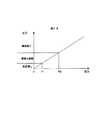
また、図5は上記の圧力センサが検出する圧力に対する図4に示す指先19の状態の判定(この判定は、後述する制御部によってなされる)を示す図であり、横軸にタッチパネル9にかかる圧力(タッチパネル9を押す力:以下、押圧力という)Pを示し、縦軸に押圧力Pに対する判定結果を示す。
【0041】
図5において、予め弱い圧力P1の値と強い圧力P2の値とが設定されており、タッチパネル9への押圧力Pが0≦P<P1のとき、タッチパネル9への押圧力無し(反応無し:タッチされていない)とし、P1≦P<P2のとき、タッチパネル9にタッチされたと判定し(上記の「タッチ検知」)、そのタッチ位置の検出が行なわれる。また、押圧力PがP2≦Pのときには、タッチパネル9には、これが押し込まれるような強い押圧力が掛かったことになり、タッチパネル9が押し込まれたと判定する(上記の「圧力検知」)。
【0042】
図4(a)に示す状態は、図5での0≦P<P1の状態を示すものであって、この状態では、タッチパネル9にタッチされていないと判定される。また、図4(b)は指先19がタッチパネル9にタッチした状態を示すものであるが、このとき、0≦P<P1であれば、図5から、タッチパネル9にタッチされていないと判定するし、P1≦P<P2であれば、タッチパネル9にタッチされただけで押し込まれてはいないと判定される。図4(c)は指先19でタッチパネル9を押し込むようにタッチした状態を示すものであり、図5において、P2≦Pの状態である。このときには、タッチパネル9が押し込まれると判定される。
【0043】
以上のようにして、この実施形態では、タツチパネル9の圧力による2段階検知を可能としている。
【0044】
なお、上記の圧力P1(>0)は、例えば、振動などによってタッチパネル9に不当な圧力が掛かった場合、タッチパネル9がタッチされたという誤判定を防止するために設定されたものである。
【0045】
図6は第1の実施形態での回路構成の一具体例の要部を示すブロック図であって、20は制御部、21はスピーカ、22は記憶部、23は振動部であり、図1,図3に対応する部分には同一符号を付けて重複する説明を省略する。
【0046】
図6において、タッチパネル9がタッチセンサと圧力センサとを備えており、このタッチセンサの検出出力と圧力センサの検出圧力Pとが制御部20に供給される。制御部20は、タッチセンサの検知出力により、タッチパネル9での指先のタッチ位置を検出し、この検出圧力Pを基に、図5で説明した判定を行ない、その判定結果に応じて、記憶部22に記憶されているデータを基に、後述するように、表示パネル8や映出装置17を制御し、また、スピーカ21で所定の音声再生を行なわせる。
【0047】
また、制御部20は、圧力センサの検出圧力Pが、予め設定されている圧力値P1,P2に対し、P<P1(タッチされていない)であるか、P1≦P<P2(タッチされたか:「タッチ検知」)であるか、P2≦P(押し込みがなされたか:「圧力検知」)であるかが判定し、かかる判定に基づいて駆動モータ11を制御する。
【0048】
図7をもとに、駆動モータ11による表示画面2の駆動量を説明するが、この図7は、図2(a)に示す状態のときの表示画面2の位置を基準にして、この基準位置からの駆動量を表わしている。
【0049】
図7(a)において、制御部20は、P<P1と判定したときには、駆動モータ11による表示画面2の駆動量をゼロとして、表示画面2を図2(a)に示す状態に設定する。そこで、例えば、図2(b)または(c)に示す状態にあるとき、制御部20は、P<P1の判定をすると、駆動モータ11を、その角度センサの検出出力をもとに、反時計廻り方向に回転制御し、リンク機構14などの振動部23を駆動して図2(a)に示す状態にする。また、制御部20は、P1≦P<P2と判定したときには、駆動モータ11を回転制御して、図2(b)に示す状態とし(これを、駆動1という)、P2≦Pと判定したときには、同様にして駆動モータ11を回転制御して、図2(c)に示す状態とする(これを、駆動2という)。
【0050】
なお、図7(a)において、駆動1の駆動量を0とし、P2≦Pのときのみ、駆動2を実行することもできる。指先による押圧力PがP1≦P<P2のときには、画面表示の変化や音声案内を行ない、P2≦Pのときにのみ駆動を行なうことによっても、決定操作が実行されたことを操作者に確実に認識させることができ、かつ駆動制御を単純化することができる。
【0051】
図7(b)は、圧力の増加に対して駆動量を連続的に変化させる例である。指先による押圧力PがP2≦Pになると、圧力変化による駆動力の変化が急増する。これは、物理的なキーを押す際にある押し込み位置を境にボタンが急に押し込まれるのに近似しており、タツチパネルでありながら、物理的なキーを押したような触覚が得られる。
【0052】
図7(c)は、指先による押圧力PがP1≦P<P2のときには、押圧力の増加に応じて駆動量が押圧方向に連続的に増加し、押圧力PがP1≦P<P2のときには、押圧力とは逆の方向に駆動する例である。この例によれば、押し込み操作を行なったときに、タッチ状態とは全く逆の方向に駆動が行なわれるため、決定操作が実行されたことを明確に認識させることができる。
【0053】
図8は制御部20のかかる機能制御の第1の具体例を示すフローチャートである。なお、以下では、図5に示すように、この圧力Pが0≦P<P1であるときの制御部20による処理をA、P1≦P<P2であるときの制御部20による処理をB、P2≦Pであるときの制御部20による処理をCとする。これらの処理については後述するが、処理Aは、当然のことながら、タッチパネル9へのタッチ操作もなされていないときの処理である。
【0054】
同図において、図示しない電源がオンとされると、制御部20は処理Aを行なって装置を動作開始状態にする(ステップ100)。そして、まず、電源をオフするなどして動作の終了条件が設定されたか否か判定し(ステップ101)、設定されていない場合には、図6での圧力センサからその検出圧力Pを取り込み、P≧P1かどうか判定する(ステップ102)。P<P1のときには、タッチパネル9へのタッチ操作もなされていないとして、ステップ100に戻り、タッチ操作がなされるまで、ステップ100〜102の一連の動作が繰り返され、その間処理Aが実行される。このときの表示画面2(図1)に表示される処理Aによる画面を▲1▼とする。
【0055】
次に、図4(b)または(c)に示すように、タッチパネル9へのタッチ操作がなされると、P≧P1(これは、P≧P2も含む)となるから(ステップ102)、まず、図4(b)または(c)に示すようにタッチパネル9での指先19でタッチされた位置(タッチ位置)が、操作ボタンなどのタッチ操作部材の処理B,Cを実行するべき位置であるか否かを判定する(ステップ103)。ここで、タッチセンサ(図6)により、指先19のタッチ位置を検出し、これを記憶部22(図6)のデータと比較して、このタッチ位置が処理B,Cの実行を必要とする位置、例えば、タッチ操作部材を操作ボタンとして、操作ボタンの表示エリア(以下、操作ボタンエリアという)内にあるかどうかを判定し、表示画面2で操作ボタンエリア内にタッチ位置があるときには、まず、処理Bを実行するとともに(ステップ104)、駆動モータ11(図6)を制御して振動部23、即ち、リンク機構14を動作させ、表示画面2の駆動1(図7)を実行するが(ステップ105)、タッチ位置が操作ボタンエリア内にないときには、P≧P1である限り、ステップ103にあって処理Aの実行を継続し、その後、P<P1となった場合には(タッチパネル9から指先19を離す)、図示しないが、ステップ100に戻り、また、指先19が移動してタッチ位置が操作ボタンエリア内に入ると、これがタッチされたものと判定して処理Bと駆動1とを実行する(ステップ104,105)。このときの表示画面2(図1)に表示されるこの処理Bによる画面を▲2▼とする。
【0056】
この駆動1の実行により、図1の構成を例にとると、図2(b)に示す状態となり、表示画面2が筐体1の開口1aから少し後退して引っ込んだ状態となる。このように、操作ボタンのいずれかのエリアに触ると、その瞬間表示画面2がカタッと小さく、あるいはゆっくりと小さく後退するが、これら操作ボタン以外のエリアに触っても、表示画面2では、何の変化もないから、操作ボタンのエリアに触ったことが触覚で認識することができる。例えば、表示画面2を斜めに見て視差が生じた場合でも、操作ボタンに触れたか否かが簡単にわかるし、また、目の不自由な人でも、正確に操作ボタンにタッチすることができる。
【0057】
そして、圧力センサからその検出圧力Pを取り込んで判定し、P<P1であるときには(ステップ106)、処理Bを終了して(ステップ107)ステップ100に戻るが、P1≦Pであるときには(ステップ106)、さらに、P2≦Pであるか否かを判定し(ステップ108)、この判定の結果、P1≦P<P2であるときには、ステップ103に戻り、P1≦P<P2である限り、処理Bと駆動1をそのまま継続して実行する。また、P2≦Pのときには(ステップ108)、タッチ位置が操作ボタンのエリア内にあるとき、処理Cを実行するするとともに(ステップ108)、駆動2(図7)を実行する(ステップ110)。このときの表示画面2(図1)に表示される処理Cによる画面を▲3▼とする。
【0058】
この処理Cは、操作ボタンに対しては、先の第1の実施形態と同様、例えば、その決定処理に相当するものであり、このとき同時に実行される駆動2は、表示画面2をガタンと大きくさらに押し込むものである。従って、表示画面2で表示される操作ボタンで実行操作を行なうと、これと同時に表示画面2が押し込まれるように動作するものであるから、ハード構成のスイッチを押し込み操作したのと同様の感触を得ることができ、大きな視差でもってこの操作ボタンの決定操作を行なっても、かかる操作をしたか否かを正確に判断することができるし、また、目が不自由な人も、上記の駆動1の実行に続く駆動2の実行により、決定操作が実行されたことを確実に知ることができる。
【0059】
なお、駆動2は、図7(c)で示したように、表示画面を元に戻す方向(指先による押圧方向とは逆の方向)に移動させてもよい。駆動2の移動が駆動1と不連続な移動であれば、押し込んだことが指で認識でき、決定操作が実行されたことを知ることができる。
【0060】
処理Cと駆動2を実行してから、タッチパネル9から指先19を離すと、P<P2となるから(ステップ111)、処理Cを終了し(ステップ112)、処理103に戻るが、このとき、P<P1であれば、処理100に戻る。
【0061】
このようにして、図4(b)に示すように指先19がタッチパネル9での操作ボタンエリアに触れた状態にしてP1≦P<P2とすると、処理Bと駆動1が行なわれ、また、図4(c)に示すように指先19でタッチパネル9での操作ボタンを押し込むようにタッチすると、P2≦Pとなり、処理Bの実行を経て処理Cと駆動2を実行することになる。
【0062】
次に、かかる動作による表示画面2での画面の具体例について説明する。
図9は、タッチ操作部材を操作ボタンとして、かかる画面の具体例を示す図である。
【0063】
図9(a)は表示画面2に操作ボタン24が表示され、この操作ボタン24をタッチ操作すると、表示色が処理A,B,Cで変化する場合の具体例を示すものである。図8のステップ100〜102の動作では、処理Aが行なわれて画面▲1▼が表示され、この画面▲1▼で、いま、第1の色により、操作ボタン24が表示されているものとする。
【0064】
かかる表示状態で指先19でこの操作ボタン24のエリアをタッチすると、このときのタッチパネル9に対する圧力PがP1≦P<P2であるときには(図8のステップ102)、このとき、タッチセンサ(図6)により、このときの指先19のタッチ位置が検出され、このタッチ位置が、記憶部22(図6)でのデータを基に、操作ボタン24のエリア内にある(即ち、操作ボタン位置と一致している)と判定されると(ステップ103)、処理Bが実行され(図8のステップ104)、操作ボタン24が第2の色に変化した画面▲2▼が表示される。これとともに、図7での駆動1が実行され(図8のステップ105)、図2(a)に示す状態から図2(b)に示す状態に移り、表示画面2がガタッと小さく、もしくはゆっくりと小さく奥の方に後退する。以上の処理Bと駆動1により、指先19が操作ボタン24にタッチしたことが、視覚的にも、また、触覚的にも、認識できる。
【0065】
さらに、指先19で操作ボタン24を押し込むようにし、これにより、P2≦Pとなると、この場合も、タツチ位置が操作ボタン24の位置と一致していると、操作ボタン24が第3の色に変化した画面▲3▼が表示され、これとともに、図7に示す駆動2が実行されて、図2(b)に示す状態から図2(c)に示す状態に急速に移り、表示画面2がガタンと大きく奥の方に後退する(なお、図7(c)の場合には、逆に前進する)。これにより、この操作ボタン24で実行操作などの機能操作が行なわれたことが(即ち、間違いなくこの操作ボタン24を操作したことが)、視覚的にも、また、触覚的にも、認識できる。従って、誤った操作がなされたときには、これを容易に知ることができて、タッチ操作のやり直しを簡単に行なうことができ、誤操作防止も向上する。タッチパネル9から指先19を離すと、画面▲1▼に戻る。
【0066】
図9(b)は表示画面2で操作ボタン24にタッチ操作すると、その形状が処理A,B,Cで変化する場合の具体例を示すものである。この具体例も、図8のステップ100〜102の動作では、処理Aが行なわれて画面▲1▼が表示され、この画面▲1▼で、例えば、操作ボタン24が矩形状で表示されているものとする。
【0067】
かかる表示状態で指先19でこの操作ボタン24の位置(エリア)をタッチすると、このときのタッチパネル9に対する圧力PがP1≦P<P2であるときには(図8のステップ102)、このとき、タッチセンサ(図6)により、このときの指先19のタッチ位置が検出され、このタッチ位置が、記憶部22(図6)でのデータを基に、操作ボタン24の位置と一致していると判定されると(図8のステップ103)、処理Bが実行され(図8のステップ104)、操作ボタン24の形状が矩形状から他の形状に変化した画面▲2▼が表示される。これとともに、図7の駆動1が実行され(図8のステップ105)、図2(a)に示す状態から図2(b)に示す状態に移り、表示画面2がガタッと小さく、もしくはゆっくりと小さく奥の方に後退する。以上の処理Bと駆動1により、指先19が操作ボタン24にタッチしたことが、視覚的にも、また、触覚的にも、認識できる。
【0068】
さらに、指先19で操作ボタン24を押し込むようにし、P2≦Pとなると、この場合も、タツチ位置と操作ボタン24の位置とが一致していると、操作ボタン24が第3の形状(画面▲1▼でのもとの形状でもよい)に変化した画面▲3▼が表示される。この場合、操作ボタン24の色も変化させるようにしてもよい。これとともに、図7の駆動2が実行されて、図2(b)に示す状態から図2(c)に示す状態に急速に移り、表示画面2がガタンと大きく奥の方に後退する(なお、図7(c)の場合には、逆に前進する)。これにより、この操作ボタン24で実行操作などの機能操作が行なわれたことが(即ち、間違いなくこの操作ボタン24を操作したことが)、視覚的にも、また、触覚的にも、認識でき、上記同様の効果が得られる。タッチパネル9から指先19を離すと、画面▲1▼に戻る。
【0069】
図9(c)は表示画面2で操作ボタン24にタッチ操作すると、そのサイズが処理A,B,Cで変化する場合の具体例を示すものである。この具体例も、図8のステップ100〜102の動作では、処理Aが行なわれて画面▲1▼が表示され、この画面▲1▼で、例えば、操作ボタン24が矩形状で表示されているものとする。
【0070】
かかる表示状態で指先19でこの操作ボタン24の位置(エリア)をタッチすると、このときのタッチパネル9に対する圧力PがP1≦P<P2であるときには(図8のステップ102)、このとき、タッチセンサ(図6)により、このときの指先19のタッチ位置が検出され、このタッチ位置が、記憶部22(図6)でのデータを基に、操作ボタン24の位置と一致していると判定されると(図8のステップ103)、処理Bが実行され(図8のステップ104)、操作ボタン24のサイズが、例えば、大きく変化した画面▲2▼が表示される。これとともに、図7の駆動1が実行され(図8のステップ105)、図2(a)に示す状態から図2(b)に示す状態に移り、表示画面2がガタッと小さく、もしくはゆっくりと小さく奥の方に後退する。以上の処理Bと駆動1により、指先19が操作ボタン24にタッチしたことが、視覚的にも、また、触覚的にも、認識できる。
【0071】
さらに、指先19で操作ボタン24を押し込むようし、P2≦Pとなると、この場合も、タツチ位置と操作ボタン24の位置とが一致していると判定されると、操作ボタン24のサイズが前とは異なる(画面▲1▼でのもとのサイズでもよい)に変化した画面▲3▼が表示される。この場合、操作ボタン24の色も変化させるようにしてもよい。これとともに、図7の駆動2が実行されて、図2(b)に示す状態から図2(c)に示す状態に急速に移り、これにより、表示画面2がガタンと大きく奥の方に後退する(但し、図7(c)の場合には、逆に前進する)。これにより、この操作ボタン24で実行操作などの機能操作が行なわれたことが(即ち、間違いなくこの操作ボタン24を操作したことが)、視覚的にも、また、触覚的にも、認識でき、上記同様の効果が得られる。次いで、タッチパネル9から指先19を離すと、画面▲1▼に戻る。
【0072】
なお、以上の操作ボタンの操作に関する処理では、処理Bは操作ボタンの選択処理、処理Cは操作ボタンによる機能を決定する決定処理とすることができる。
【0073】
また、図9(a)〜(c)において、画面▲3▼の隣合う2つの辺部に影25を表示し、画面▲3▼が押されてへこんでいることを視覚的に表わすようにしてもよい。
【0074】
図10は図8に示す動作に伴う表示画面2での画面の他の具体例を示す図である。
【0075】
まず、図10(a)はタッチ操作部材を操作ボタンとし、パソコンでのマウスオーバーと同様の機能を持たせたものである。
【0076】
表示画面2に操作ボタン24が表示され、この操作ボタン24をタッチ操作すると、付加情報が表示されるようにした具体例を示すものである。図8のステップ100〜102の動作では、処理Aが行なわれて操作ボタン24が表われた画面▲1▼が表示されているものとする。
【0077】
かかる表示状態で指先19でこの操作ボタン24のエリアをタッチすると、このときのタッチパネル9に対する圧力PがP1≦P<P2であるときには(図8のステップ102)、このとき、タッチセンサ(図6)により、このときの指先19のタッチ位置が検出され、このタッチ位置が、記憶部22(図6)でのデータを基に、操作ボタン24の位置と一致していると判定されると(図8のステップ103)、処理Bが実行され(図8のステップ104)、例えば、「このボタンを押すと次の画面に進みます」といったような案内メッセージ(即ち、この操作ボタン24の機能)を表わす吹き出し26が表示された画面▲2▼が表示される。また、これとともに、図7の駆動1が実行されて(図8のステップ105)、図2(a)に示す状態から図2(b)に示す状態に移り、表示画面2がガタッと小さく、もしくはゆっくりと小さく奥の方に後退する。以上の処理Bと駆動1により、指先19が操作ボタン24にタッチしたことが、視覚的にも、また、触覚的にも、認識できる。
【0078】
次いで、指先19でさらに操作ボタン24を押し込むようして、P2≦Pとなると、この場合も、タツチ位置が操作ボタン位置と一致していることを判定して、例えば、操作ボタン24の色が変化した画面▲3▼が表示される。これとともに、図7の駆動2が実行されて、図2(b)に示す状態から図2(c)に示す状態に急速に移り、表示画面2がガタンと大きく奥の方に後退する(但し、図7(c)の場合には、逆に前進する)。これにより、この操作ボタン24で実行操作などの機能操作が行なわれたことが(即ち、間違いなくこの操作ボタン24を操作したことが)、視覚的にも、また、触覚的にも、認識でき、上記と同様の効果が得られる。タッチパネル9から指先19を離すと、画面▲1▼に戻る。
【0079】
この具体例でも、処理Bは操作ボタンの選択処理、処理Cは操作ボタンによる機能を決定する決定処理とすることができる。
【0080】
また、画面▲3▼の隣合う2つの辺部に影25を表示し、画面▲3▼が押されてへこんでいることを視覚的に表わすようにしてもよい。
【0081】
以上の機能は、パソコンなどのマウスを移動させて所定の表示要素に一致させると、その表示要素に変化を与える、所謂「マウスオーバー」に相当するものであって、この実施形態では、タッチによるP1≦P<P2の状態と押し込みのP2≦Pの状態とに区分して、夫々毎に処理Bと処理Cとを行なわせるようにしたことにより、タッチパネルを備えた表示装置でかかるマウスオーバー機能を可能としている。
【0082】
なお、ここでは、吹き出し26によって操作ボタン24の機能を説明するようにしたが、スピーカ21(図6)から音声メッセージを出力するようにしてもよいし、この音声メッセージと吹き出し26とを組み合わせるようにしてもよい。
【0083】
図10(b)はタッチ操作部材をメッセージとしたものであり、表示画面2で表示されるメッセージの表示エリアの部分をタッチすると、その部分が拡大して表示させることができるようにした具体例を示すものである。
【0084】
この具体例も、図8のステップ100〜102の動作では、処理Aが行なわれて画面▲1▼が表示され、この画面▲1▼では、例えば、「いらっしゃいませ」といったような案内メッセージ27が表示されているものとする。
【0085】
かかる表示状態で指先19でこの案内メッセージ27の表示エリアをタッチすると、このときのタッチパネル9に対する圧力PがP1≦P<P2であるときには(図8のステップ102)、このとき、タッチセンサ(図6)により、このときの指先19のタッチ位置が検出され、このタッチ位置が、記憶部22(図6)でのデータを基に、案内メッセージ27の表示エリアと一致していると判定されると、処理Bが実行され(図8のステップ104)、指先19のタッチ位置を中心とした所定領域がこれを含む拡大表示領域28に拡大して表示されることになる。従って、案内メッセージ27の一部を拡大表示させることができ、同じタッチ状態として指先19を案内メッセージ27に沿って移動させることにより、この拡大表示領域28を移動(ドラッグ)させることができる。従って、このようにドラッグさせることにより、虫眼鏡で文章を拡大して読んでいくように、案内メッセージ27を拡大してみることができる。また、これとともに、図7の駆動1が実行されて(図8のステップ105)、図2(a)に示す状態から図2(b)に示す状態に移り、表示画面2がガタッと小さく、もしくはゆっくりと小さく奥の方に後退する。以上の処理Bと駆動1により、指先19が操作ボタン24にタッチしたことが、視覚的にも、また、触覚的にも、認識できる。
【0086】
次いで、指先19でこの案内メッセージ27の表示エリアを押し込むようして、P2≦Pにすると、この場合も、タツチ位置と案内メッセージ27の表示エリアとの一致を判定して、「決定」処理などの処理Cが行なわれて画面▲3▼が表示され、この決定処理が終了すると、これに続く処理に移っていく。また、これとともに、図7の駆動2が実行して、図2(b)に示す状態から図2(c)に示す状態に急速に移り、表示画面2がガタンと大きく奥の方に後退する(但し、図7(c)の場合には、逆に前進する)。これにより、この案内メッセージ27に対する機能操作が行なわれたことが(即ち、間違いなくこの案内メッセージ27の表示エリアをタッチ操作したことが)、視覚的にも、また、触覚的にも、認識でき、上記と同様の効果が得られる。また、このとき、画面▲3▼の隣合う2つの辺部に影25を表示し、画面▲3▼が押されてへこんでいることを視覚的に表わすようにしてもよい。タッチパネル9から指先19を離すと、画面▲1▼に戻る。
【0087】
図10(c)はタッチ操作部材をメニュー画面とカーソルとするものであり、表示画面2でタッチパネル9にタッチ操作すると、メニュー欄が表示されて、所望とするメニューを選択決定できるようにした具体例を示すものである。
【0088】
この具体例も、図8のステップ100〜102の動作では、処理Aが行なわれて画面▲1▼が表示されるが、この画面▲1▼では、背景模様(図示せず)以外、何も表示されていないものとする。
【0089】
かかる画面▲1▼の任意の位置を指先19でタッチすると、このときのタッチパネル9に対する検出圧力PがP1≦P<P2であるときには(図8のステップ102)、このとき、タッチセンサ(図6)により、このときの指先19のタッチ位置が検出され、このタッチ位置が、記憶部22(図6)でのデータを基に、画面▲1▼内の位置と判定されると、処理Bが実行され(図8のステップ104)、複数のメニューからなるメニュー欄29が表示された画面▲2▼が表示される。また、これとともに、図7の駆動1が実行されて(図8のステップ105)、図2(a)に示す状態から図2(b)に示す状態に移り、表示画面2がガタッと小さく、もしくはゆっくりと奥の方に後退する。以上の処理Bと駆動1により、指先19が操作ボタン24にタッチしたことが、視覚的にも、また、触覚的にも、認識できる。
【0090】
また、処理Bにより、この画面▲2▼では、メニュー欄29での指先19のタッチ位置を含むメニューにカーソル30も表示され、同じタッチ状態を保ちながら指先19を移動させると、このカーソル30もこの指先19にくっついてドラッグし、所望のメニューを選択することができる。そして、カーソル30を所望のメニューに一致させた後(このとき、指先19のタッチ位置もこの所望のメニューに一致している)、さらに、指先19でこのメニューを押し込むようし、P2≦Pにすると(ステップ108)、この場合も、タツチ位置とメニューの位置との一致を判定して、処理Cを実行し(ステップ109)、この所望メニューの決定を行なう画面▲3▼が表示される。この場合、カーソル30の色も変化させるようにしてもよい。また、これとともに、図7の駆動2が実行して、図2(b)に示す状態から図2(c)に示す状態に急速に移り、表示画面2がガタンと大きく奥の方に後退する(但し、図7(c)の場合には、逆に前進する)。これにより、この案内メッセージ27に対する機能操作が行なわれたことが(即ち、間違いなくこの案内メッセージ27の表示エリアをタッチ操作したことが)、視覚的にも、また、触覚的にも、認識でき、上記と同様の効果が得られる。このとき、画面▲3▼の隣合う2つの辺部に影25を表示し、画面▲3▼が押されてへこんでいることを視覚的に表わすようにしてもよい。タッチパネル9から指先19を離すと、画面▲1▼に戻る。
【0091】
このように、図10(b),(c)で示す具体例は、拡大表示領域28やカーソル30といったポイントを移動させ、選択した位置で決定を行なうマウスでのドラッグと決定との機能を持たせたものである。
【0092】
なお、以上説明した第1の具体例では、タッチ操作部材の種類(即ち、操作ボタン24や案内メッセージ27,カーソル29といったもの)に応じて、処理Cを実行させるための押し込み圧力(=P2)を異ならせるようにしてもよい。例えば、「削除」ボタンのような操作に注意を要する操作ボタン24に対しては、他のタッチ操作部材に比べてより強く押さない限り、機能(即ち、処理Cを実行)しないようにすることができる。これにより、間違えて押し込み操作しても、機能しにくいようにする。
【0093】
図11は本発明によるタッチパネルを備えた表示装置をATM(Automatic Tellers Machine:自動預入支払機)の表示装置とし、これに上記の第1の具体例を用いたときの画面を示す図であり、前出図面に対応する部分には同一符号を付けている。ここでは、図9(a),(c)及び図10(a),(b)に示す画面変化を用いたものとしている。
【0094】
いま、図6に示すような回路構成をもつATMの図3(b)に示すような構成の表示画面2に、図11(a)に示す初期画面▲1▼が表示されているものとする(図8のステップ100)。この初期画面▲1▼では、「お引き出し」ボタン,「お預け入れ」ボタン,……などといった顧客が銀行に対して行なう行為を選択できるようにした選択ボタン24や顧客に対する案内メッセージ27が表示されており、いま、顧客が預金の引き出しのために、「お引き出し」ボタン24を指先19で軽くタッチすると、制御部20(図6)は、このときの検出圧力PがP1≦Pと判定したときには(図8のステップ102,103)、ATMの表示画面に図11(b)に示すような案内画面▲2▼を表示させる(図8のステップ104)。この案内画面▲2▼では、図9(c)に示す画面▲2▼のように、指先19でタッチされたこの「お引き出し」ボタン24が拡大され、かつ図9(a)に示す画面▲2▼のように、色を変えて表示され、さらに、図10(a)に示す画面▲2▼のように、例えば、「お客様の預金口座から現金を引き出すことができます。通帳またはカードが必要です」といったような預金を引き出す場合の案内がこの「お引き出し」ボタン24からの吹き出し26によって表示される。この場合、図示しないスピーカからこの案内を音声出力するようにしてもよい。この場合、上記図7の駆動1が実行される(図8のステップ105)。
【0095】
なお、かかる案内画面▲2▼において、指先19で「お引き出し」ボタン24で押し込むようにし、検出圧力PがP2≦Pとなるようにすると(図8のステップ108)、この「お引き出し」ボタン24の選択が決定し、図示しない次の画面に移って預金引き出しのための操作ができるようになる(図8のステップ109)。この場合、上記図7の駆動2が実行される(図8のステップ110)。
【0096】
また、図11(a)に示す初期画面▲1▼で、検出圧力PがP1≦Pとなるように、案内メッセージ27の表示部分を指先19でタッチすると、図10(b)の画面▲2▼のように、拡大表示領域28を表示させ、そのタッチ位置を含む所定の範囲の部分をこの拡大表示領域28で拡大表示させる図11(c)に示す案内画面▲2▼を表示させることもできる。この場合、かかるタッチ状態で指先19をこの案内メッセージ27に沿って移動させると、この案内メッセージ27の一連の文字列を順に拡大され、これにより、案内メッセージ27を拡大してみることができる。
【0097】
図12は本発明によるタッチパネルを備えた表示装置を券売機の表示装置とし、これに上記の第1の具体例を用いたときの画面を示す図であり、前出図面に対応する部分には同一符号を付けている。ここでは、図10(b)に示す画面変化を用いたものとしている。
【0098】
いま、図6に示すような回路を有し、図1または図2に示すような構成の券売機の表示画面2に、図10(a)に示す初期画面▲1▼が表示されているものとする。この初期画面▲1▼では、路線と主要駅が表示されており、これ以外の駅は表示されていない(図8のステップ100)。
【0099】
顧客が希望する駅までの乗車券(勿論、特急券や指定券などを購入できるようにしてもよい)を購入する場合、この希望駅が初期画面▲1▼に表示されているときには、その表示位置を指先19で強く押すことにより、図8のステップ102〜106,108が行なわれ、図12(c)に示すような購入用画面▲3▼が表示され、これにより、直ちに運賃が判り、乗車券を購入することができる(図8のステップ109)。この場合、勿論、特急券や指定券などの他のチケットも購入できるようにしてもよい。
【0100】
初期画面▲1▼に顧客が希望する駅が表示されていないときには、表示される路線に指先でタッチする。このタッチによって制御部20(図6)がP1≦Pと判定すると(図8のステップ102)、そのタッチ位置が表示されないで隠れた駅の表示位置に一致したときには(図8のステップ103)、制御部20は、これを検知して、図12(b)に示すような案内画面▲2▼を表示させる(図8のステップ104)。この案内画面▲2▼では、図10(b)の画面▲2▼,▲3▼のように、指先19のタッチ位置に拡大表示領域28を設け、この中に、駅名などにより、この駅があることを拡大して表示させる。この拡大表示される駅が顧客の希望しない駅の場合には、指先を路線に沿って移動させる。これにより、この指先19のタッチ位置が駅の位置と一致する毎に、その駅名などを拡大表示した拡大表示領域28が表示され、顧客は、希望する駅を探すことができる。希望した駅が見つかり、その駅名の部分を押し込むように指先19で押圧すると(この場合、上記の駆動2が実行される)、その駅が選択決定されたことになり、図12(c)に示すような購入用画面▲3▼が表示され(図8のステップ109)、希望する駅までの乗車券などを購入することができる。
【0101】
このようにして、券売機では、その表示画面に広い範囲の区間での路線を同時に表示することができ、そこで表示されていない駅までのチケットも簡単な操作で持って購入することができる。
【0102】
なお、この券売機としては、鉄道の場合を例としたが、バス路線,船舶,航空路などであってもよいことはいうまでもない。
【0103】
また、図12(b)に示す案内画面▲2▼では、券売する範囲全体の路線を同時に表示するようにしてもよいが、この範囲の一部を表示し、指先19が画面▲2▼の端部に達すると、これに続く部分の表示に切り替わるようにしてもよい。勿論、この場合には、新しく表示された路線では、前に表示された路線でのタッチ位置が明らかになるようにする。これにより、券売する路線範囲を拡張することができる。
【0104】
次に、本発明によるタッチパネルを備えた表示装置の第2の実施形態について説明する。但し、この第2の実施形態も、図1〜図6で示す第1の実施形態と同様の構成をなし、また、図7,図8で示した動作をなすものである。
【0105】
図13はこの第2の実施形態の図8に示す制御動作によって表示画面2に表示される画面の一具体例を示す図である。
【0106】
同図において、いま、表示画面2に、操作ボタン24a〜24cが表示されており、この表示画面2に指先19でタッチしたものとする。この指先19のタッチによって圧力センサ(図6)で検出される圧力PがP1≦Pとなったとすると(ステップ102)、制御部20は、タッチセンサ(図6)の検出結果から、この指先19のタッチ位置を検出し、これを記憶部22(図6)のデータと比較して、このタッチ位置が所定の機能(即ち、処理B,C)を実行すべきエリア内(ここでは、操作ボタン24a〜24cのエリア内のいずれか)にあるかどうか判定する(ステップ103)。ここで、タッチ位置が、例えば、操作ボタン24bのエリア内にあるとすると、制御部20は、まず、処理Bを実行し(ステップ104)、駆動モータ11(図6)を制御して振動部23、即ち、リンク機構14を動作させ、図7の駆動1を実行するが(ステップ105)、操作ボタン24a〜24cのエリア内のいずれにもタッチ位置が存在しない場合、即ち、これら操作ボタン24a〜24cのいずれにもタッチしていないときには、P≧P1である限り、ステップ103にあって処理Aの実行を継続し、その後、P<P1となった場合には(タッチパネル9から指先19を離すと)、図示しないが、ステップ100に戻り、また、指先19が移動してそのタッチ位置が操作ボタン24a〜24cのいずれかのエリア内に入ると、これがタッチされたものとして、処理Bを実行し(ステップ104)、駆動モータ11(図6)を制御して振動部23、即ち、リンク機構14を動作させ、図7の駆動1を実行する(ステップ105)。
【0107】
この駆動1の実行により、図1の構成を例にとると、図2(b)に示す状態となり、表示画面2が筐体1の開口1aから少し後退して引っ込んだ状態となる。このように、操作ボタン24a〜24cの1つに触ると、その瞬間表示画面2がカタッと小さく、またはゆっくりと小さく後退し、これら操作ボタン24a〜24c以外の部分を触っても、表示画面2では、何の変化もないから、操作ボタン24a〜24cに触ったことが触覚で認識することができ、例えば、表示画面2を斜めに見て視差が生じた場合でも、操作ボタンに触れたか否かが簡単にわかるし、また、目の不自由な人でも、正確に操作ボタンにタッチすることができる。
【0108】
なお、この具体例では、処理Bは必ずしも必要なものではなく、少なくとも駆動1が実行されればよい。
【0109】
そして、圧力センサからその検出圧力Pを取り込んで判定し、P<P1であるときには(ステップ106)、処理Bと駆動1の実行を終了して(ステップ107)ステップ100に戻る。また、P1≦Pであるときには(ステップ106)、さらに、P2≦Pであるか否かを判定し(ステップ108)、この判定の結果、P1≦P<P2であるときには、ステップ103に戻り、P1≦P<P2である限り、処理Bと駆動1とをそのまま継続して実行する。また、P2≦Pのときには(ステップ108)、指先19のタッチ位置が操作ボタン24a〜24cのいずれかのエリアと一致しているとき、処理Cを実行し(ステップ109)、図7に示す駆動2を実行する(ステップ110)。
【0110】
この処理Cは、操作ボタン24a〜24cに対しては、先の具体例と同様、その決定処理に相当するものであり、このとき同時に実行される駆動2は、表示画面2をさらに押し込むものである。従って、表示画面2で表示される操作ボタン24a〜24cで実行操作を行なうと、これと同時に表示画面2が押し込まれるように動作するものであるから、ハード構成のスイッチを押し込み操作したのと同様の感触を得ることができ、大きな視差でもってこの操作ボタンの決定操作を行なっても、かかる操作をしたか否かを正確に判断することができるし、また、目が不自由な人も、上記の駆動1の実行に続く駆動2の実行(表示画面2の後退または前進)により、決定操作が実行されたことを確実に知ることができる。
【0111】
処理Cと駆動2との実行中にタッチパネル9から指先19を離すと、P<P2となるから(ステップ111)、処理Cを終了させ(ステップ112)、ステップ103に戻るが、このとき、P<P1であれば、ステップ100に戻る。ここで、処理Cは先の具体例での処理Cと同様の処理であるが、この具体例では、必ずしも必要なものではなく、少なくとも駆動2が実行されればよい。
【0112】
この具体例の一応用例として、図14により、ATMに応用した場合について説明する。
【0113】
同図(a)はATM31の表示画面2での複数の操作ボタン24からなるボタン群のうちの所望とする1つの操作ボタン24に指先19でタッチし、検出圧力PがP1≦P<P2であるときを示すものである。ボタン群の輪郭に影32を表示することにより、かかるボタン群が浮き上がって見えるように表示している。この場合には、図8のステップ104により、表示画面2で指先19でタッチされた操作ボタン24が、例えば、色が変わるなどの処理Bが実行されるとともに、図8のステップ105により、表示画面8がATM31の筐体1の開口で奥に沈み込む図7の駆動1が実行される。
【0114】
そして、さらに、決定操作のために、この操作ボタン24を押し込むようにする操作を行ない、P2≦Pとなると、図14(b)に示すように、図8のステップ109により、この操作された操作ボタン24の2つの辺部に、この操作ボタン24が押し込められて見えるように、影部33を現わす処理Cが実行されるとともに、図8のステップ110により、表示画面8がATM31の筐体1の開口でさらに奥に沈み込む、もしくは浮き上がる図7の駆動2が実行される。
【0115】
このように、平面な表示画面2で表示される操作ボタン24が、これがタッチ操作されたときには、駆動1,2の実行により、感覚的にもハードのボタンを操作したときと同様であるし、また、視覚的にも、操作ボタンが押し込まれたように認識されることになり、良好な操作感が得られることになる。また、影部33の幅や濃さを表示画面の移動量に対応するように表示することにより、さらに良好な操作考えられる。
【0116】
他の応用例として、図15により、これもATMに応用した場合について説明する。
【0117】
同図(a)はATM31の表示画面2での複数の操作ボタン24が個々に分離されてなるボタン群のうちの所望とする1つの操作ボタン24に指先19でタッチし、検出圧力PがP1≦P<P2であるときを示すものである。これら操作ボタン24には夫々、その輪郭に影32を表示することにより、これら操作ボタン24が浮き上がって見えるように表示している。この場合には、図8のステップ104により、表示画面2で指先19でタッチされた操作ボタン24が、例えば、色が変わるなどの処理Bが実行されるとともに、図8のステップ105により、表示画面8がATM31の筐体1の開口で奥に沈み込む図7の駆動1が実行される。
【0118】
そして、さらに、決定操作のために、この操作ボタン24を押し込むようにする操作を行ない、P2≦Pとなると、図15(b)に示すように、図8のステップ109により、このように操作された操作ボタン24では、これが押し込められて見えるように、影部が除かれる処理Cが実行されるとともに、図8のステップ110により、表示画面2がATM31の筐体1の開口でさらに奥に沈み込む、もしくは浮き上がる図7の駆動2が実行される。
【0119】
このように、この応用例においても、先の応用例と同様、平面な表示画面2で表示される操作ボタン24が、これがタッチ操作されたときには、駆動1,2の実行により、感覚的にもハードのボタンを操作したときと同様であるし、また、視覚的にも、操作ボタンが押し込まれたように認識されることになり、良好な操作感が得られることになる。
【0120】
この応用例においても、押し込まれると消えていく影の部分の幅や濃さを表示画面の移動量に対応するように表示することにより、さらに良好な操作考えられる。
【0121】
次に、本発明によるタッチパネルを備えた表示装置の第3の実施形態について説明する。
この第3の実施形態も、上記第1,第2の実施形態と同様の図1〜図6に示す構成をなすものであり、表示画面2が任意の駆動量をとることができるようにしたものである。
【0122】
図16はかかる第3の実施形態の制御部20(図6)の制御動作を示すフローチャートであり、以下、画面の表示例をもってこの動作を説明する。
【0123】
また、図17はこの制御動作での表示画面2に表示される画面の例を示すものであり、ここでは、表示画面2の初期位置を図2(a)に示す状態での位置と図2(c)に示す状態での位置との中間の位置とする。
【0124】
同図において、図示しない電源がオンとされると、先の第1の実施形態に対する図8と同様に、制御部20は表示装置を動作開始状態にする(ステップ200)。表示画面2では、例えば、図17(a)に示すように、突起を示す画像(以下、突起部という)34a〜34cが表示されているものとする。そして、まず、電源をオフするなどして動作の終了条件が設定されたか否か判定し(ステップ201)、設定されていない場合には、図6での圧力センサからその検出圧力Pを取り込み、P≧P1かどうか判定する(ステツプ202)。P<P1のときには、タッチパネル9(図1〜図3)へのタッチ操作もなされていないとして、ステップ200に戻り、タッチ操作がなされるまで、ステップ200〜202の一連の動作が繰り返されて表示画面2が初期位置に設定されたままとする。
【0125】
いま、表示画面2において、図17(a)に示すように、突起部34a〜34c以外のエリア(以下、背景エリアという)35内の点Sに指先19でタッチし、タッチしたまま指先19を、突起部34a〜34cを横切るように、矢印Y方向に移動させるものとすると、指先19が点Sにタッチしたときには、制御部20は圧力センサの検出圧力PがP1≦Pとなったことからこのタッチを検出し(ステツプ202)、また、制御部20は、タッチセンサによって検出したこのタッチ位置と記憶部22(図6)のデータとにより、このタッチ位置が背景エリア35内にあることを検知し、上記の初期状態のままで待機する(ステップ203)。指先19をタッチパネル9から離すと、P<P1となるから、ステップ200に戻り、ステップ200〜202の一連の動作が繰り返される。
【0126】
次に、指先19を、タッチパネル9にタッチしたまま、矢印Y方向に移動させると、指先19は突起部34aに達するが、制御部20は、圧力センサ(図6)の検出圧力Pから指先19がタッチパネル9にタッチしていることを検知しつつ、タッチセンサで検出されるタッチ位置と記憶部22のデータとからタッチ位置が突起部34aのエリア内にあることを検知し、駆動モータ11(図1,図2,図3)を回転制御してリンク機構14を駆動し、表示画面2を図2(a)に示す状態にする(ステップ204)。これにより、表示画面2が上記の初期位置から持ち上がった状態となる。
【0127】
指先19が矢印Y方向に移動してタッチが継続しているときには(ステップ205)、ステップ203に戻り、以下、指先19がタッチパネル9にタッチしている限り、ステップ203〜205の一連の動作が繰り返されることになり、指先19の矢印Y方向への移動につれて、指先19のタッチ位置が突起部34a,34b間の背景エリア35内に入ると、制御部20はこれを検出して駆動モータ11を逆方向に回転制御し、リンク機構14を駆動して表示画面2を初期位置に戻す。そして、指先19のタッチ位置が次の突起部34bのエリア内に入ると、制御部20はこれを検知し、同様にして、表示画面2を図2(a)に示す状態の位置に移し、表示画面2が持ち上がった状態にする。
【0128】
このようにして、指先19のタッチ位置が背景エリア34から突起部34a〜34cのエリアに移る毎に、表示画面2は初期位置の状態から図2(a)の状態に移って持ち上がった状態となり、逆に、指先19のタッチ位置が突起部34a〜34cのエリアから背景エリア35に移る毎に、表示画面2は図2(a)の状態から初期位置の状態に移って下げられた状態となる。従って、図17(a)に示す表示画面2で指先19をタッチしたまま矢印Y方向へ移動させると、突起部34a,34b,34c毎に表示画面2が持ち上がり、これら突起部34a,34b,34cが画面から突起しているように感じられるようになる。
【0129】
なお、突起部34a〜34cが凹んだくぼみ部を表わすものであるときには、図16のステップ204では、表示画面2を初期位置から図2(c)で示す状態の位置に移される。
【0130】
図17(b)は表示画面2での他の表示例を示すものであって、ここで表示される突起部36はお碗型の突起を表わすものとする。この表示例のときの図16に示す動作を説明する。
【0131】
図17(b)に示す表示画面2において、背景エリア35内の位置Sから指先19をタッチパネル9にタッチしたまま矢印Y方向に、突起部36を横切るように、移動させると、指先19がタッチする前はステップ200〜202の一連の動作が繰り返され、指先19がタッチパネル9にタッチして圧力P1≦Pが検出されると(ステツプ202)、ステップ203に移って表示画面2を図2(c)に示す初期状態に維持したままとする。
【0132】
そして、指先19のタッチ位置が突起部36内に入ると、制御部20は、上記と同様にして、これを検出し、駆動モータ11を回転制御してリンク機構14を駆動する(ステップ204)。ここで、このような位置に応じて高さが変化する突起部36に対しては、その位置と高さとの関係を示すデータが記憶部22(図6)に格納されており、制御部20は、検出したタッチ位置に対応した高さデータを記憶部22から読み取り、この高さデータに応じて駆動モータ11(図6)を回転制御することにより、この高さデータに応じた駆動量でリンク機構14を駆動する。この結果、表示画面2は、図17(b)で図示するように、例えば、円弧状に変化する駆動量で駆動されて、指先19のタッチ位置が突起部36の周辺部から中央部に向かうにつれて、初期位置にある表示画面2が矢印A方向とは逆方向に連続的に移動することにより、次第に持ち上げられて図2(a)に示すような状態となり、次いで、指先19のタッチ位置が中央部から突起部36の周辺部に向かうにつれて、図2(a)に示すような状態から矢印A方向に連続的に移動し、次第に下げられていって元の初期位置に戻る。
【0133】
このようにして、連続的に高さが変化するように表わされる突起部に対しては、表示画面2がタッチ位置の変化に応じて連続的に駆動されるものであるから、平面的な表示画面2に表示される突起部も、感覚的に突出しているように認識できることになる。このようにして、突起部にタッチしていることを確実に認識でき、かかる突起部にタッチしたつもりが、実際にこれにタッチしていないことも確実に知ることができ、所望とする突起部へタッチしているか否かの確認が容易となる。
【0134】
なお、突起部36の代わりに、お碗型に凹んだくぼみ部を表わすものであるときには、図16のステップ204では、表示画面2を初期状態から図2(c)で示す状態の方に移すようにする。この場合も、突起部36と同様の効果が得られる。
【0135】
また、ここでは、突起部36をお碗型のものを表わしているものとしたが、高さまたは深さが任意に変化するようなものでもよく、例えば、地図のようなものであっても、表示画面2で2次元的に表示されていても、表示画面2を地表の高さに応じて上記のように移動することにより、感覚的にその高さも認識することができるようになり、3次元的に表示された地図として認識することが可能となる。
【0136】
図17(c)は表示画面2でのさらに他の表示例を示すものであって、ここで表示される突起部37は面積が広い平らな突起を表わすものとする。この表示例のときの図16に示す動作を説明する。
【0137】
図17(c)に示す表示画面2において、背景エリア35内の位置Sから指先19をタッチパネル9にタッチしたまま矢印Y方向に、突起部37を横切るように、移動させると、指先19がタッチする前は図16のステップ200〜202の一連の動作が繰り返され、指先19がタッチパネル9にタッチして圧力P1≦Pが検出されると(ステツプ202)、ステップ203に移って表示画面2を初期位置に維持したままとする。
【0138】
そして、指先19のタッチ位置が突起部37内に入ると、制御部20は、上記と同様にして、これを検出し、駆動モータ11を回転制御してリンク機構14を駆動する(ステップ204)。ここでは、このような面積が広くて平坦な突起部37に対しては、記憶部22(図6)には、表示画面2を初期位置から図2(a)に示す位置の方向に移動させて振動させるためのデータが格納されており、制御部20は、指先19のタッチ位置がかかる突起部37のエリア内にあることを検出すると、記憶部22からかかるデータを読み出して駆動モータ11を往復回転制御する。これにより、駆動モータ11は、初期位置から図2(a)に示す位置の方向に移動した後、小きざみに回転方向を交互に反転し、これにより、図17(c)に示すように駆動量が変化して、表示画面2は振動することになる。
【0139】
勿論、指先19のタッチ位置が背景エリア35から突起37のエリアに移ったときには、表示画面2を初期位置から図2(a)に示す位置の方向に移動させるものであるが、図17(c)に示すような広くて平らな突起部37の場合、タッチ位置がかかる突起部37内に長く存在する可能性もあり、このような場合には、時間経過とともに、かかる突起部37にタッチしていることの意識がなくなることになるが、上記のように、表示画面2を振動させることにより、このような突起部37にタッチしていることを常に認識させることができる。
【0140】
なお、ここでは、平らな突起部37を例としたが、平らなくぼみ部であるときには、表示画面2を初期位置から図2(c)に示す位置の方向に移動させ、そこで振動させるようにする。
【0141】
次に、本発明によるタッチパネルを備えた表示装置の第4の実施形態について説明する。
この第4の実施形態は、上記第3の実施形態において、突起部を操作ボタンとするものであり、上記第3の実施形態の動作にこれら操作ボタンの機能の実行のための動作を付加したものである。
【0142】
図18はかかる第4の実施形態の制御動作を示すフローチャートであって、ステップ200〜206は第3の実施形態の図16で示す動作と同様である。また、ここでは、図17に示す突起部34a〜34c,36,37を夫々操作ボタンとする。
【0143】
図19はこの第4の実施形態での圧力Pに対する表示画面への作用(反応)を示す図である。
【0144】
同図において、ステップ200〜206の一連の動作は図16で説明した動作と同様であり、説明を省略する。但し、ここでは、同じ表示画面2に図17(a)〜(c)に示すような操作ボタンが表示されるが、形状,サイズが異なる操作ボタンは機能,用途なども異なるものとする。
【0145】
図16で説明したように、指先19が操作ボタンにタッチして圧力PがP1≦P<P2であるときには、図19に示すように、表示画面2の駆動が行なわれるが、図17(a),(b),(c)の操作ボタン34a〜34c,36,37毎に、表示画面2の駆動の仕方が異なり(ステップ204)、これにより、操作ボタンの機能や用途が異なっており、これにより、所望とする操作ボタンにタッチしたことを感覚的に認識することができる。
【0146】
以上の状態で指先19でタッチしている操作ボタンを押し込むようにする操作をし、そのときの圧力センサの検出圧力PがP2≦Pになると(ステップ301)、制御部20は、そのときの指先19のタッチ位置が操作ボタンのエリア内であるときには(ステップ302)、図19に示すように、この操作ボタンの機能(例えば、決定など)が実行される(ステップ303)。そして、この操作ボタンの押し込みが終わると(ステップ304)、ステップ203に戻って次の操作を待つ。
【0147】
このようにして、この第4の実施形態では、操作ボタンに応じて表示画面2の駆動の仕方が異なるので、これでもってどの操作ボタンにタッチしたかを触ったことによって知ることができる。
【0148】
【発明の効果】
以上説明したように、本発明によると、指示手段による押圧力Pを検知する検知手段と、この押圧力PがP1≦P<P2であるときにタッチ操作部材に関する第1の処理を、P1≦P<P2からP2≦Pに変化したときにタッチ操作部材に関する第2の処理を行なう制御部とを設け、押圧力PがP1≦P<P2からタッチ操作部材が押し込められるとするP2≦Pに変化したとき、この第2の処理により、表示画面を指示手段による押圧方向に移動させる機能を実行させるものであるから、所望とするタッチ操作部材を押し込んだことを、触覚的に、容易にかつ確実に確認することもできる。
【図面の簡単な説明】
【図1】本発明によるタッチパネルを備えた表示装置の第1の実施形態を示す構成図である。
【図2】図1における移動機構の動作を示す図である。
【図3】本発明によるタッチパネルを備えた表示装置の第1の実施形態での移動機構を有する表示手段の他の具体例を概略的に示す図である。
【図4】図1におけるタッチパネルに対する指先の状態を示す図である。
【図5】圧力センサが検出する圧力に対する図4に示す指先の状態の判定を示す図である。
【図6】図1に示す実施形態での回路構成の具体例の要部を示すブロック図である。
【図7】図1に示す第1の実施形態での圧力センサの検出圧力に対する表示画面の駆動量を示す図である。
【図8】図6における制御部の機能制御の第1の具体例を示すフローチャートである。
【図9】図8に示す動作で図1での表示面に表示される画面の具体例を示す図である。
【図10】図8に示す動作で図1での表示面に表示される画面の他の具体例を示す図である。
【図11】本発明の第1の実施形態をATMの表示装置として、これに図9及び図10に示す画面例を用いたときの画面を示す図である。
【図12】本発明の第1の実施形態をATMの表示装置として、これに図9及び図10に示す画面例を用いたときの他の画面を示す図である。
【図13】本発明によるタッチパネルを備えた表示装置の第2の実施形態の表示画面を示す図である。
【図14】本発明の第2の実施形態を用いたATMの動作と画面の一具体例を示す図である。
【図15】本発明の第2の実施形態を用いたATMの動作と画面の他の具体例を示す図である。
【図16】本発明によるタッチパネルを備えた表示装置の第3の実施形態の制御動作を示すフローチャートである。
【図17】図16に示す動作での表示画面における画面例を示す図である。
【図18】本発明によるタッチパネルを備えた表示装置の第4の実施形態の制御動作を示すフローチャートである。
【図19】図18に示す動作での検出圧力に対する表示画面への作用(動作)を示す図である。
【符号の説明】
1 筐体
1a 開口
2 表示画面
8 表示パネル
8a 表示面
9 タッチパネル
10,10a,10b 支持部材
11 駆動モータ
12 回転歯車
13 平歯車
14 リンク機構
14a,14b リンク
14c,14d 支持部材
15,16 引張バネ
17 映出装置
18 ミラー
19 指先
20 制御部
21 スピーカ
22 記憶部
23 振動部
24,24a〜24c 操作ボタン
25 影部
26 吹き出し
27 案内メッセージ
28 拡大表示領域
29 メニュー欄
30 カーソル
31 ATM
32,33 影部
34a〜34c 突起部
35 背景エリア
36,37 突起部[0001]
BACKGROUND OF THE INVENTION
The present invention relates to a display device provided with a touch panel used in a stationary or portable terminal device.
[0002]
[Prior art]
In recent years, terminal devices have been widely used in various industries. For example, ATMs (Automatic Tellers Machines) are installed at banks, and ticket machines and map guides are installed at stations, etc., so that a part of business such as banks and stations can be covered by terminal devices. I have to. Also, in stores such as fast food stores, terminal devices may be used for merchandise order processing (for example, Japanese Patent Application Laid-Open No. 5-216687), and content using a communication network such as the Internet. A terminal device that receives the distribution of a message, a terminal device for browsing the web, and the like have also been realized or proposed.
[0003]
By the way, in such a terminal device, a display device is provided, and various operations as described above can be performed by operating input means such as a keyboard while viewing information such as messages displayed on the display screen. The display screen has a function as an input means, and various operations can be performed by operating the screen according to messages and menus displayed on the display screen. Display devices having a touch panel have been used.
[0004]
According to such a display device equipped with a touch panel, since the operation is performed by directly touching the display screen with a fingertip, it is easy to operate and there are few operational errors. In addition, the operation unit such as the keyboard can reduce the number of operation buttons, so the terminal device itself can be downsized, the installation area can be reduced, and the degree of freedom of installation location in the store or on the premises Benefits such as increased will also be obtained.
[0005]
[Problems to be solved by the invention]
However, in a display device equipped with a conventional touch panel, an image of an input unit made of a touch operation member such as an operation button (touch button) is displayed on the display screen, so that the input unit is recognized visually by a customer or a user. Then, based on this recognition, the operation is performed by touching the place where the image of the input means is desired to be operated, and the following problems arise.
[0006]
First, since the touch operation area of the touch operation member for the user to perform a touch operation is displayed on the display screen, the touch operation area is on the same plane as the part other than the touch operation area. Differently, the feeling of touching the touch operation area is the same as the feeling of touching the other parts. For this reason, even if the position touched with the fingertip deviates from a desired touch operation area, it may not be noticed.
[0007]
In particular, when several operation buttons are displayed as a touch operation member with a guidance message, etc., these operation buttons may be displayed around the display screen, and the operation buttons displayed in this way are operated. In this case, the touch position of the fingertip may deviate from the desired display position of the operation button. Even if such a deviation is slight, this operation button is not touched and does not function. However, the user intends to touch the operation button, and may not notice that the operation button is not touched. For this reason, the same operation switch will be touched again. For this purpose, it is necessary to recognize that the touch switch has not been touched, but this recognition will require a certain amount of time. There was a problem.
[0008]
In addition, many operation buttons may be displayed close to each other on the display screen at the same time. In such a case, each operation button is displayed in a relatively small size, so that the touch position of the fingertip is desired. If the display position of the operation button slightly deviates, the adjacent operation button may be touched. A display device having a conventional touch panel is configured to function immediately when a displayed operation button is touched, so that when the touch position is shifted and the adjacent operation button is touched, this adjacent operation button is displayed. Functioned, and there was a problem that this function had to be stopped and then operated again.
[0009]
An object of the present invention is to solve such a problem and easily recognize that a touch operation member such as an operation button displayed on a display screen is touched with a fingertip or the like, and further, easily operate the touch operation member. It is another object of the present invention to provide a display device including a touch panel that can be reliably recognized.
[0010]
[Means for Solving the Problems]
In order to achieve the above object, the present invention provides a touch panel for detecting a touch position of an instruction means on a display screen of a display panel, and allows a touch operation member displayed on the display screen to be touched for operation. Provided with detection means for detecting the pressing force P by the instruction means when touch-operating the touch operation member, and preset pressures P1 and P2 (where P1 <P2) are provided. When the detected pressure P by P1 is P1 ≦ P <P2, the first processing relating to the touch operation member pressed by the instruction means is performed, and when the pressing force P changes from P1 ≦ P <P2 to P2 ≦ P, A control unit that performs a second process on the touch operation member pressed by the means, and the first process includes:The selection process of the operation button displayed on the display screen, andThe display screen is moved in the pressing direction by the instruction means, and the amount of movement is continuously changed according to the increase of the pressing force P, and the pressing operation member is pushed from P1 ≦ P <P2. When changing to P2 ≦ P,The selection process of the selected operation button is performed, andIn the second process, the function of further moving the display screen in the pressing direction by the instruction means is executed.PushThe rate of change in the amount of movement relative to the increase in pressure isPushIt is assumed that it is larger than the rate of change of the moving amount with respect to the increase in pressure.
[0011]
Further, the present invention is a display device including a touch panel provided with a touch panel for detecting a touch position of the instruction unit on the display screen of the display panel, and capable of touching and operating a touch operation member displayed on the display screen. The detection means for detecting the pressing force P by the instruction means when touching the touch operation member, and preset pressures P1 and P2 (where P1 <P2) are provided, and the detection pressure P by the detection means is P1. When ≦ P <P2, the first process related to the touch operation member pressed by the instruction unit is performed, and when the pressing force P changes from P1 ≦ P <P2 to P2 ≦ P, the touch pressed by the instruction unit A control unit that performs a second process on the operation member;It is a selection process of the operation button displayed on the display screenWhen the first process executes a function of moving the display screen in the pressing direction by the instruction means, and the pressing force P changes from P1 ≦ P <P2 to P2 ≦ P where the touch operation member is pressed,This is a process for determining the operation button that has been selected.By the second process, a function of moving the display screen in the direction opposite to the pressing direction by the instruction unit is executed.
[0012]
AndFurthermore, it has a drive motor for driving the display screen, the control means drives the drive motor in accordance with the pressing force P detected by the detection means, and the display screen in the first process and the second process Are moved by the drive motor.
[0013]
Also,A plurality of touch operation members are displayed on the touch panel, and the set pressure P2 varies depending on the type of the touch operation member.
[0015]
DETAILED DESCRIPTION OF THE INVENTION
Hereinafter, embodiments of the present invention will be described with reference to the drawings.
FIG. 1 is a block diagram showing a first embodiment of a display device having a touch panel according to the present invention. FIG. 1 (a) is an external perspective view, FIG. 1 (b) is a side view, and FIG. Is a housing, 1a is an opening, 2 is a display screen, 3 is a mounting portion, 4 is a stand, 5 is a rotating shaft, 6 is a pin hole, 7 is a pin, 8 is a display panel, and 8a is a display panel. Display surface, 9 is a touch panel, 10, 10a and 10b are support members, 11 is a drive motor, 12 is a rotating gear, 13 is a spur gear, 14 is a link mechanism, 14a and 14b are links, 14c and 14d are support members, 15 , 16 are tension springs.
[0016]
In the figure, a
[0017]
An attachment portion 3 is integrally provided on the back side opposite to the
[0018]
Although the orientation of the
[0019]
Thus, the pin hole 6 and the
[0020]
As shown in FIG. 1 (c), the
[0021]
The
[0022]
In FIG. 1 (c), this moving mechanism is configured using the
[0023]
As a specific configuration example of the moving mechanism, a
[0024]
Further, the other end of the
[0025]
The display means including the
[0026]
FIG. 2 is a view showing the operation of the moving mechanism, and the same reference numerals are given to portions corresponding to FIG.
[0027]
FIG. 2 (a) shows the initial state of the
[0028]
When the
[0029]
When the
[0030]
When the
[0031]
Here, although a gear mechanism is used as the driving means of the
[0032]
FIG. 3 is a sectional view schematically showing another specific example of the display means having the moving mechanism in the
[0033]
3A, in the
[0034]
The
[0035]
In the specific example shown in FIG. 3B, a projector including a
[0036]
The
[0037]
This specific example also has a function of detecting the pressure when the
[0038]
However, when the touch position of the fingertip is detected on the
[0039]
FIG. 4 is a diagram showing a state of a fingertip with respect to the
[0040]
FIG. 5 is a diagram showing determination of the state of the
[0041]
In FIG. 5, when the value of the weak pressure P1 and the value of the strong pressure P2 are set in advance, and the pressure P to the
[0042]
The state shown in FIG. 4A indicates a state of 0 ≦ P <P1 in FIG. 5, and in this state, it is determined that the
[0043]
As described above, in this embodiment, two-stage detection based on the pressure of the
[0044]
The pressure P1 (> 0) is set to prevent an erroneous determination that the
[0045]
FIG. 6 is a block diagram showing a main part of a specific example of the circuit configuration in the first embodiment, in which 20 is a control unit, 21 is a speaker, 22 is a storage unit, and 23 is a vibration unit. , Parts corresponding to those in FIG.
[0046]
In FIG. 6, the
[0047]
The
[0048]
The drive amount of the
[0049]
In FIG. 7A, when it is determined that P <P1, the
[0050]
In FIG. 7A, the driving amount of driving 1 is set to 0, and driving 2 can be executed only when P2 ≦ P. When the pressing force P by the fingertip is P1 ≦ P <P2, the screen display is changed and voice guidance is performed, and driving is performed only when P2 ≦ P, the operator can be sure that the determination operation has been executed. Can be recognized, and the drive control can be simplified.
[0051]
FIG. 7B is an example in which the drive amount is continuously changed with respect to the increase in pressure. When the pressing force P by the fingertip becomes P2 ≦ P, the change in the driving force due to the pressure change increases rapidly. This is similar to a sudden pressing of a button at the pressing position when a physical key is pressed, and a tactile sensation as if the physical key was pressed is obtained even though it is a touch panel.
[0052]
FIG. 7C shows that when the pressing force P by the fingertip is P1 ≦ P <P2, the driving amount continuously increases in the pressing direction according to the increase of the pressing force, and the pressing force P is P1 ≦ P <P2. This is an example of driving in the direction opposite to the pressing force. According to this example, when the pushing operation is performed, the driving is performed in the direction completely opposite to the touch state, so that the determination operation can be clearly recognized.
[0053]
FIG. 8 is a flowchart showing a first specific example of the function control of the
[0054]
In the figure, when a power supply (not shown) is turned on, the
[0055]
Next, as shown in FIG. 4 (b) or (c), when a touch operation on the
[0056]
When the
[0057]
Then, the detected pressure P is taken from the pressure sensor and determined. When P <P1 (step 106), the process B is ended (step 107) and the process returns to step 100, but when P1 ≦ P (step 106). 106) Further, it is determined whether or not P2 ≦ P (step 108). If the result of this determination is that P1 ≦ P <P2, the process returns to step 103, and as long as P1 ≦ P <P2, the processing is continued. B and drive 1 are continuously executed as they are. When P2 ≦ P (step 108), when the touch position is within the area of the operation button, the process C is executed (step 108) and the drive 2 (FIG. 7) is executed (step 110). The screen by the process C displayed on the display screen 2 (FIG. 1) at this time is represented by (3).
[0058]
This process C corresponds to the determination process for the operation buttons, for example, as in the first embodiment, and the
[0059]
Note that, as shown in FIG. 7C, the
[0060]
When the
[0061]
In this way, if P1 ≦ P <P2 with the
[0062]
Next, a specific example of the screen on the
FIG. 9 is a diagram showing a specific example of such a screen using the touch operation member as an operation button.
[0063]
FIG. 9A shows a specific example in which the
[0064]
When the area of the
[0065]
Further, the
[0066]
FIG. 9B shows a specific example when the
[0067]
When the position (area) of the
[0068]
Further, when the
[0069]
FIG. 9C shows a specific example in the case where the size of the
[0070]
When the position (area) of the
[0071]
Further, when the
[0072]
In the processing related to the operation button operation described above, the process B can be an operation button selection process, and the process C can be a determination process for determining a function by the operation button.
[0073]
9 (a) to 9 (c), shadows 25 are displayed on two adjacent sides of the screen (3) so that the screen (3) is depressed and depressed visually. May be.
[0074]
FIG. 10 is a diagram showing another specific example of the screen on the
[0075]
First, in FIG. 10A, a touch operation member is used as an operation button, which has the same function as mouse over on a personal computer.
[0076]
An
[0077]
When the area of the
[0078]
Next, when the
[0079]
Also in this specific example, the process B can be an operation button selection process, and the process C can be a determination process for determining a function by the operation button.
[0080]
Alternatively, the
[0081]
The above function corresponds to so-called “mouse over”, in which when a mouse such as a personal computer is moved and matched with a predetermined display element, the display element is changed. The mouse over function is applied to the display device equipped with the touch panel by dividing the state of P1 ≦ P <P2 and the state of push-in P2 ≦ P and performing the processing B and the processing C respectively. Is possible.
[0082]
Here, the function of the
[0083]
FIG. 10B shows a touch operation member as a message, and when the part of the display area of the message displayed on the
[0084]
Also in this specific example, in the operations of
[0085]
When the display area of the
[0086]
Next, when the display area of the
[0087]
FIG. 10C shows the touch operation member as a menu screen and a cursor. When a touch operation is performed on the
[0088]
In this specific example as well, in the operations of
[0089]
When an arbitrary position on the screen {circle around (1)} is touched with the
[0090]
Also, by processing B, on this screen {circle around (2)}, the
[0091]
As described above, the specific examples shown in FIGS. 10B and 10C have the functions of dragging and deciding with the mouse that moves the points such as the
[0092]
In the first specific example described above, the pressing pressure (= P2) for executing the process C according to the type of the touch operation member (that is, the
[0093]
FIG. 11 is a diagram showing a screen when the display device provided with the touch panel according to the present invention is an ATM (Automatic Tellers Machine) display device, and the above first specific example is used for this. Parts corresponding to those in the previous drawings are given the same reference numerals. Here, the screen changes shown in FIGS. 9A and 9C and FIGS. 10A and 10B are used.
[0094]
Now, assume that the initial screen (1) shown in FIG. 11 (a) is displayed on the
[0095]
In this guidance screen {circle over (2)}, when the “drawer”
[0096]
Further, on the initial screen (1) shown in FIG. 11 (a), when the display portion of the
[0097]
FIG. 12 is a view showing a screen when the display device provided with the touch panel according to the present invention is used as a ticket vending machine display device and the first specific example is used for the display device. The same reference numerals are given. Here, the screen change shown in FIG. 10B is used.
[0098]
6 having the circuit shown in FIG. 6 and displaying the initial screen (1) shown in FIG. 10 (a) on the
[0099]
When purchasing a ticket to a station desired by a customer (of course, you may be able to purchase a limited express ticket or a designated ticket), if this desired station is displayed on the initial screen (1), the display When the position is strongly pressed with the
[0100]
When the station desired by the customer is not displayed on the initial screen (1), the displayed route is touched with a fingertip. When the control unit 20 (FIG. 6) determines that P1 ≦ P by this touch (
[0101]
In this way, the ticket vending machine can simultaneously display routes in a wide range on the display screen, and tickets to stations not displayed there can be purchased with a simple operation.
[0102]
In addition, as this ticket vending machine, although the case of the railroad was taken as an example, it cannot be overemphasized that a bus route, a ship, an air route, etc. may be sufficient.
[0103]
In addition, in the guidance screen (2) shown in FIG. 12 (b), the route of the entire range to be sold may be displayed at the same time, but a part of this range is displayed, and the
[0104]
Next, a second embodiment of a display device provided with a touch panel according to the present invention will be described. However, the second embodiment also has the same configuration as that of the first embodiment shown in FIGS. 1 to 6 and performs the operations shown in FIGS.
[0105]
FIG. 13 is a diagram showing a specific example of a screen displayed on the
[0106]
In this figure, it is assumed that the
[0107]
When the
[0108]
In this specific example, the process B is not necessarily required, and at least the
[0109]
Then, the detected pressure P is taken from the pressure sensor and determined. When P <P1 (step 106), the execution of the process B and the
[0110]
This process C corresponds to the determination process for the
[0111]
If the
[0112]
As an application example of this specific example, the case of application to ATM will be described with reference to FIG.
[0113]
FIG. 5A shows that a desired
[0114]
Further, for the determination operation, an operation to push in the
[0115]
As described above, when the
[0116]
As another application example, a case where this is also applied to ATM will be described with reference to FIG.
[0117]
In FIG. 5A, a desired
[0118]
Further, for the determination operation, an operation to push in the
[0119]
As described above, in this application example, as in the previous application example, when the
[0120]
Also in this application example, a better operation can be considered by displaying the width and darkness of the shadow portion that disappears when pressed in such a way as to correspond to the amount of movement of the display screen.
[0121]
Next, a third embodiment of a display device including a touch panel according to the present invention will be described.
The third embodiment also has the same configuration as shown in FIGS. 1 to 6 as the first and second embodiments, and the
[0122]
FIG. 16 is a flowchart showing the control operation of the control unit 20 (FIG. 6) of the third embodiment. Hereinafter, this operation will be described with a display example of a screen.
[0123]
FIG. 17 shows an example of a screen displayed on the
[0124]
In the figure, when a power supply (not shown) is turned on, the
[0125]
Now, on the
[0126]
Next, when the
[0127]
When the
[0128]
In this way, each time the touch position of the
[0129]
Note that when the
[0130]
FIG. 17B shows another display example on the
[0131]
In the
[0132]
When the touch position of the
[0133]
Since the
[0134]
If it represents a hollow portion recessed in the bowl shape instead of the
[0135]
Here, the
[0136]
FIG. 17C shows still another display example on the
[0137]
In the
[0138]
When the touch position of the
[0139]
Of course, when the touch position of the
[0140]
Here, the
[0141]
Next, a fourth embodiment of a display device including a touch panel according to the present invention will be described.
In the fourth embodiment, the projection is an operation button in the third embodiment, and an operation for executing the function of these operation buttons is added to the operation of the third embodiment. Is.
[0142]
FIG. 18 is a flowchart showing the control operation of the fourth embodiment, and steps 200 to 206 are the same as the operation shown in FIG. 16 of the third embodiment. Here, the
[0143]
FIG. 19 is a diagram showing the action (reaction) on the display screen with respect to the pressure P in the fourth embodiment.
[0144]
In the same figure, a series of operations in
[0145]
As shown in FIG. 16, when the
[0146]
When the operation button touched with the
[0147]
In this way, in the fourth embodiment, since the
[0148]
【The invention's effect】
As described above, according to the present invention, the detection unit that detects the pressing force P by the instruction unit, and the first process relating to the touch operation member when the pressing force P is P1 ≦ P <P2, And a control unit that performs a second process relating to the touch operation member when P <P2 changes to P2 ≦ P, and the pressing force P satisfies P2 ≦ P when the touch operation member is pushed in from P1 ≦ P <P2. When changed, the second process executes a function of moving the display screen in the pressing direction by the instruction means. Therefore, it is tactilely and easily detected that the desired touch operation member is pushed in. It can also be confirmed reliably.
[Brief description of the drawings]
FIG. 1 is a configuration diagram illustrating a first embodiment of a display device including a touch panel according to the present invention.
FIG. 2 is a diagram illustrating an operation of a moving mechanism in FIG.
FIG. 3 is a diagram schematically showing another specific example of display means having a moving mechanism in the first embodiment of a display device including a touch panel according to the present invention.
4 is a diagram showing a state of a fingertip with respect to the touch panel in FIG. 1. FIG.
5 is a diagram showing determination of the state of the fingertip shown in FIG. 4 with respect to the pressure detected by the pressure sensor.
6 is a block diagram showing a main part of a specific example of a circuit configuration in the embodiment shown in FIG. 1;
7 is a diagram showing a display screen drive amount with respect to a detected pressure of the pressure sensor in the first embodiment shown in FIG. 1; FIG.
8 is a flowchart showing a first specific example of function control of the control unit in FIG. 6;
9 is a diagram showing a specific example of a screen displayed on the display screen in FIG. 1 by the operation shown in FIG.
10 is a diagram showing another specific example of the screen displayed on the display screen in FIG. 1 by the operation shown in FIG.
11 is a diagram showing a screen when the first embodiment of the present invention is used as an ATM display device and the screen examples shown in FIG. 9 and FIG. 10 are used for the ATM display device. FIG.
12 is a diagram showing another screen when the screen display example shown in FIGS. 9 and 10 is used as the ATM display device according to the first embodiment of the present invention. FIG.
FIG. 13 is a diagram showing a display screen of a second embodiment of a display device including a touch panel according to the present invention.
FIG. 14 is a diagram showing a specific example of an ATM operation and screen using the second embodiment of the present invention.
FIG. 15 is a diagram showing another specific example of an ATM operation and a screen using the second embodiment of the present invention.
FIG. 16 is a flowchart showing a control operation of the third embodiment of the display device including the touch panel according to the present invention.
17 is a diagram showing a screen example on the display screen in the operation shown in FIG. 16;
FIG. 18 is a flowchart showing a control operation of a display device having a touch panel according to a fourth embodiment of the present invention.
19 is a diagram showing an action (operation) on the display screen with respect to the detected pressure in the operation shown in FIG.
[Explanation of symbols]
1 housing
1a opening
2 Display screen
8 Display panel
8a Display surface
9 Touch panel
10, 10a, 10b Support member
11 Drive motor
12 Rotating gear
13 Spur gear
14 Link mechanism
14a, 14b link
14c, 14d Support member
15, 16 Tension spring
17 Projection device
18 Mirror
19 Fingertip
20 Control unit
21 Speaker
22 Memory unit
23 Vibration part
24, 24a-24c Operation buttons
25 Shadow
26 Speech balloon
27 Information message
28 Enlarged display area
29 Menu field
30 cursor
31 ATM
32, 33 Shadow
34a-34c Projection
35 Background area
36, 37 Projection
Claims (4)
Translated fromJapanese該タッチ操作部材をタッチ操作する際の該指示手段による押圧力Pを検知する検知手段と、
予め設定圧力P1,P2(但し、P1<P2)が設けられ、該検知手段による検知圧力PがP1≦P<P2であるとき、該指示手段によって押圧された該タッチ操作部材に関する第1の処理を行ない、該押圧力PがP1≦P<P2からP2≦Pに変化したとき、該指示手段によって押圧された該タッチ操作部材に関する第2の処理を行なう制御部と
を有し、
該第1の処理は、該表示画面に表示された操作ボタンの選択処理であって、かつ、該表示画面を該指示手段による押圧方向に移動させ、その移動量が該押圧力Pの増加に応じて連続的に変化する処理であって、
該押圧力PがP1≦P<P2から該タッチ操作部材が押し込められたとするP2≦Pに変化したとき、該選択処理された該操作ボタンの決定処理が行なわれ、かつ、該第2の処理により、該表示画面を該指示手段による押圧方向にさらに移動させる機能を実行させ、
該第2の処理における該押圧力の増加に対する移動量の変化の割合が、該第1の処理における該押圧力の増加に対する移動量の変化の割合よりも大きいことを特徴とするタッチパネルを備えた表示装置。In a display device provided with a touch panel provided on a display screen of a display panel for detecting a touch position of an instruction unit and capable of being operated by touching a touch operation member displayed on the display screen,
Detection means for detecting a pressing force P by the instruction means when touch-operating the touch operation member;
Preset pressures P1 and P2 (where P1 <P2) are provided, and when the detected pressure P by the detecting means is P1 ≦ P <P2, the first processing relating to the touch operation member pressed by the indicating means And when the pressing force P changes from P1 ≦ P <P2 to P2 ≦ P, a control unit that performs a second process on the touch operation member pressed by the instruction unit, and
The first process isa selection process of the operation button displayed on the display screen, and the display screen is moved in the pressing direction by the instruction means, and the movement amount increases the pressing force P. A process that changes continuously in response,
When the pressing force P changes from P1 ≦ P <P2 to P2 ≦ P that the touch operation member is pushed in, theselection processing of the operation button subjected to the selection processing is performed, and the second processing By executing the function of further moving the display screen in the pressing direction by the instruction means,
The proportion of the movement amount of change with respect to the increase ofthe pressing forcethat put in the second process, being greater than the proportion of the movement amount of change with respect to the increase ofthe pressing forcethat put the first treatment A display device with a touch panel.
該タッチ操作部材をタッチ操作する際の指示手段による押圧力Pを検知する検知手段と、
予め設定圧力P1,P2(但し、P1<P2)が設けられ、該検知手段による検知圧力PがP1≦P<P2であるとき、該指示手段によって押圧された該タッチ操作部材に関する第1の処理を行ない、該押圧力PがP1≦P<P2からP2≦Pに変化したとき、該指示手段によって押圧された該タッチ操作部材に関する第2の処理を行なう制御部と
を有し、
該表示画面に表示された操作ボタンの選択処理である該第1の処理により、該表示画面を該指示手段による押圧方向に移動させる機能を実行させ、
該押圧力PがP1≦P<P2から該タッチ操作部材が押し込められたとするP2≦Pに変化したとき、該選択処理がなされた該操作ボタンの決定処理である該第2の処理により、該表示画面を該指示手段による押圧方向とは逆の向きに移動させる機能を実行させることを特徴とするタッチパネルを備えた表示装置。In a display device provided with a touch panel provided on a display screen of a display panel for detecting a touch position of an instruction unit and capable of being operated by touching a touch operation member displayed on the display screen,
Detection means for detecting the pressing force P by the instruction means when touch-operating the touch operation member;
Preset pressures P1 and P2 (where P1 <P2) are provided, and when the detected pressure P by the detecting means is P1 ≦ P <P2, the first processing relating to the touch operation member pressed by the indicating means And when the pressing force P changes from P1 ≦ P <P2 to P2 ≦ P, a control unit that performs a second process on the touch operation member pressed by the instruction unit, and
The firstprocess, which is the selection process of the operation button displayed on the display screen, causes the function to move the display screen in the pressing direction by the instruction means,
When the pressing force P changes from P1 ≦ P <P2 to P2 ≦ P where the touch operation member is pushed in, the secondprocess which is the determination process of the operation button in which the selection process has been performed , A display device provided with a touch panel, wherein a function of moving a display screen in a direction opposite to a pressing direction by the instruction unit is executed.
さらに、前記表示画面を駆動するための駆動モータを有し、
前記検知手段によって検知された押圧力Pに応じて、前記制御手段が該駆動モータを駆動し、前記第1の処理及び前記第2の処理における前記表示画面の移動が該駆動モータによって行なわれることを特徴とするタッチパネルを備えた表示装置。In claim 1 or 2,
And a drive motor for driving the display screen,
The control means drives the drive motor in accordance with the pressing force P detected by the detection means, and the movement of the display screen in the first process and the second process is performed by the drive motor. A display device provided with a touch panel characterized by the above.
前記タッチパネルには、複数のタッチ操作部材が表示されるものであり、該タッチ操作部材の種類によって前記設定圧力P2が異なることを特徴とするタッチパネルを備えた表示装置。In claim 1 or 2,
A display device comprising a touch panel, wherein a plurality of touch operation members are displayed on the touch panel, and the set pressure P2 varies depending on a type of the touch operation members.
Priority Applications (2)
| Application Number | Priority Date | Filing Date | Title |
|---|---|---|---|
| JP2002249192AJP4500485B2 (en) | 2002-08-28 | 2002-08-28 | Display device with touch panel |
| US10/648,289US7312791B2 (en) | 2002-08-28 | 2003-08-27 | Display unit with touch panel |
Applications Claiming Priority (1)
| Application Number | Priority Date | Filing Date | Title |
|---|---|---|---|
| JP2002249192AJP4500485B2 (en) | 2002-08-28 | 2002-08-28 | Display device with touch panel |
Related Child Applications (1)
| Application Number | Title | Priority Date | Filing Date |
|---|---|---|---|
| JP2007222067ADivisionJP4568310B2 (en) | 2007-08-29 | 2007-08-29 | Display device with touch panel |
Publications (2)
| Publication Number | Publication Date |
|---|---|
| JP2004086733A JP2004086733A (en) | 2004-03-18 |
| JP4500485B2true JP4500485B2 (en) | 2010-07-14 |
Family
ID=32056380
Family Applications (1)
| Application Number | Title | Priority Date | Filing Date |
|---|---|---|---|
| JP2002249192AExpired - LifetimeJP4500485B2 (en) | 2002-08-28 | 2002-08-28 | Display device with touch panel |
Country Status (2)
| Country | Link |
|---|---|
| US (1) | US7312791B2 (en) |
| JP (1) | JP4500485B2 (en) |
Families Citing this family (206)
| Publication number | Priority date | Publication date | Assignee | Title |
|---|---|---|---|---|
| GB9722766D0 (en) | 1997-10-28 | 1997-12-24 | British Telecomm | Portable computers |
| US7614008B2 (en)* | 2004-07-30 | 2009-11-03 | Apple Inc. | Operation of a computer with touch screen interface |
| TWI226584B (en)* | 2003-04-07 | 2005-01-11 | Darfon Electronics Corp | Input device and input method |
| JP4039344B2 (en)* | 2003-09-17 | 2008-01-30 | 株式会社日立製作所 | Display device with touch panel |
| JP2005332063A (en)* | 2004-05-18 | 2005-12-02 | Sony Corp | Input device with tactile function, information inputting method, and electronic device |
| EP1763732A2 (en)* | 2004-06-29 | 2007-03-21 | Koninklijke Philips Electronics N.V. | Discontinuous zoom |
| US8678275B1 (en)* | 2004-06-29 | 2014-03-25 | Diebold Self-Service Systems, Division Of Diebold, Incorporated | Automated banking machine that operates responsive to data bearing records |
| CN101253466A (en)* | 2004-08-02 | 2008-08-27 | 皇家飞利浦电子股份有限公司 | System and method for enabling the modeling of virtual objects |
| JP4624745B2 (en)* | 2004-09-08 | 2011-02-02 | オリンパス株式会社 | Camera and imaging operation method |
| EP1834229A2 (en)* | 2004-12-30 | 2007-09-19 | Volkswagon AG | Input device and method for the operation thereof |
| US20060170956A1 (en) | 2005-01-31 | 2006-08-03 | Jung Edward K | Shared image devices |
| US9082456B2 (en) | 2005-01-31 | 2015-07-14 | The Invention Science Fund I Llc | Shared image device designation |
| US7892096B2 (en)* | 2005-02-22 | 2011-02-22 | Wms Gaming Inc. | Gaming machine with configurable button panel |
| US20060189278A1 (en) | 2005-02-24 | 2006-08-24 | Research In Motion Limited | System and method for making an electronic handheld device more accessible to a disabled person |
| US8130197B2 (en)* | 2005-03-15 | 2012-03-06 | Ergowerx. LLC | Floating keyboard |
| US9942511B2 (en) | 2005-10-31 | 2018-04-10 | Invention Science Fund I, Llc | Preservation/degradation of video/audio aspects of a data stream |
| US9451200B2 (en) | 2005-06-02 | 2016-09-20 | Invention Science Fund I, Llc | Storage access technique for captured data |
| US9167195B2 (en) | 2005-10-31 | 2015-10-20 | Invention Science Fund I, Llc | Preservation/degradation of video/audio aspects of a data stream |
| US9191611B2 (en) | 2005-06-02 | 2015-11-17 | Invention Science Fund I, Llc | Conditional alteration of a saved image |
| US8964054B2 (en) | 2006-08-18 | 2015-02-24 | The Invention Science Fund I, Llc | Capturing selected image objects |
| US20070222865A1 (en) | 2006-03-15 | 2007-09-27 | Searete Llc, A Limited Liability Corporation Of The State Of Delaware | Enhanced video/still image correlation |
| US9967424B2 (en) | 2005-06-02 | 2018-05-08 | Invention Science Fund I, Llc | Data storage usage protocol |
| US9621749B2 (en)* | 2005-06-02 | 2017-04-11 | Invention Science Fund I, Llc | Capturing selected image objects |
| US10003762B2 (en) | 2005-04-26 | 2018-06-19 | Invention Science Fund I, Llc | Shared image devices |
| US9076208B2 (en) | 2006-02-28 | 2015-07-07 | The Invention Science Fund I, Llc | Imagery processing |
| US20060244733A1 (en)* | 2005-04-28 | 2006-11-02 | Geaghan Bernard O | Touch sensitive device and method using pre-touch information |
| JP4652118B2 (en)* | 2005-05-11 | 2011-03-16 | アルプス電気株式会社 | Display device |
| DE102005025301B4 (en) | 2005-06-02 | 2008-12-18 | Preh Keytec Gmbh | Device for manual input and display of data |
| EP1752860B1 (en)* | 2005-08-12 | 2015-03-18 | LG Electronics Inc. | Mobile terminal with touch screen providing haptic feedback and corresponding method |
| US20070064004A1 (en)* | 2005-09-21 | 2007-03-22 | Hewlett-Packard Development Company, L.P. | Moving a graphic element |
| DE102006029506B4 (en)* | 2005-10-28 | 2018-10-11 | Volkswagen Ag | input device |
| US20070120980A1 (en) | 2005-10-31 | 2007-05-31 | Searete Llc, A Limited Liability Corporation Of The State Of Delaware | Preservation/degradation of video/audio aspects of a data stream |
| US20070236474A1 (en)* | 2006-04-10 | 2007-10-11 | Immersion Corporation | Touch Panel with a Haptically Generated Reference Key |
| JP2007310496A (en)* | 2006-05-16 | 2007-11-29 | Alps Electric Co Ltd | Touch operation input device |
| JP4764274B2 (en)* | 2006-07-11 | 2011-08-31 | 京セラミタ株式会社 | Electronic device and program |
| JP2008033739A (en)* | 2006-07-31 | 2008-02-14 | Sony Corp | Touch screen interaction method and apparatus based on tactile force feedback and pressure measurement |
| JP4294668B2 (en)* | 2006-09-14 | 2009-07-15 | 株式会社日立製作所 | Point diagram display device |
| KR100794928B1 (en)* | 2006-12-29 | 2008-01-15 | 주식회사 켐트로닉스 | Touch sensing device and method capable of recognizing continuous touch |
| US7844915B2 (en) | 2007-01-07 | 2010-11-30 | Apple Inc. | Application programming interfaces for scrolling operations |
| GB2446702A (en) | 2007-02-13 | 2008-08-20 | Qrg Ltd | Touch Control Panel with Pressure Sensor |
| JP5354924B2 (en)* | 2007-02-16 | 2013-11-27 | 国立大学法人 名古屋工業大学 | Digital map creation system |
| WO2008126129A1 (en)* | 2007-03-09 | 2008-10-23 | Pioneer Corporation | Video effect device, video processor, and program |
| WO2008115408A1 (en)* | 2007-03-15 | 2008-09-25 | F-Origin, Inc. | Integrated feature for friction-less movement of force sensitive touch screen |
| US7973778B2 (en)* | 2007-04-16 | 2011-07-05 | Microsoft Corporation | Visual simulation of touch pressure |
| DE102007022085A1 (en)* | 2007-05-11 | 2008-11-13 | Continental Automotive Gmbh | Touchpadanordnung |
| DE102007023066B4 (en)* | 2007-05-16 | 2015-09-10 | Continental Automotive Gmbh | instrument cluster |
| US20080291156A1 (en)* | 2007-05-23 | 2008-11-27 | Dietz Paul H | Sanitary User Interface |
| JP2008305174A (en)* | 2007-06-07 | 2008-12-18 | Sony Corp | Information processor, information processing method, and program |
| KR20090003695A (en)* | 2007-07-03 | 2009-01-12 | 삼성전자주식회사 | Watch type mobile communication terminal using pressure sensor and its user input receiving method |
| US8976120B2 (en)* | 2007-08-13 | 2015-03-10 | Blackberry Limited | Tactile touchscreen for electronic device |
| EP2026175B1 (en) | 2007-08-13 | 2010-10-13 | Research In Motion Limited | Tactile touchscreen for electronic device |
| US20090046068A1 (en)* | 2007-08-13 | 2009-02-19 | Research In Motion Limited | Tactile touchscreen for electronic device |
| US8094130B2 (en)* | 2007-08-13 | 2012-01-10 | Research In Motion Limited | Portable electronic device and method of controlling same |
| US20090046070A1 (en)* | 2007-08-13 | 2009-02-19 | Research In Motion Limited | Tactile touchscreen for electronic device |
| KR20090019161A (en)* | 2007-08-20 | 2009-02-25 | 삼성전자주식회사 | Electronic device and how to operate it |
| US9489086B1 (en) | 2013-04-29 | 2016-11-08 | Apple Inc. | Finger hover detection for improved typing |
| KR101526963B1 (en)* | 2007-09-19 | 2015-06-11 | 엘지전자 주식회사 | Mobile terminal, method of displaying data in the mobile terminal, and method of editting data in the mobile terminal |
| US9454270B2 (en) | 2008-09-19 | 2016-09-27 | Apple Inc. | Systems and methods for detecting a press on a touch-sensitive surface |
| US20120075193A1 (en)* | 2007-09-19 | 2012-03-29 | Cleankeys Inc. | Multiplexed numeric keypad and touchpad |
| US9110590B2 (en)* | 2007-09-19 | 2015-08-18 | Typesoft Technologies, Inc. | Dynamically located onscreen keyboard |
| US10203873B2 (en) | 2007-09-19 | 2019-02-12 | Apple Inc. | Systems and methods for adaptively presenting a keyboard on a touch-sensitive display |
| US10126942B2 (en)* | 2007-09-19 | 2018-11-13 | Apple Inc. | Systems and methods for detecting a press on a touch-sensitive surface |
| US8217903B2 (en) | 2007-11-02 | 2012-07-10 | Research In Motion Limited | Electronic device and tactile touch screen |
| ATE436049T1 (en)* | 2007-11-02 | 2009-07-15 | Research In Motion Ltd | ELECTRONIC DEVICE AND TOUCH SCREEN |
| EP2056264A3 (en)* | 2007-11-05 | 2010-04-21 | Aristocrat Technologies Australia Pty. Ltd. | An assembly for a gaming machine and player interface |
| EP2060968B1 (en) | 2007-11-16 | 2011-01-12 | Research In Motion Limited | Tactile touch screen for electronic device |
| US9058077B2 (en)* | 2007-11-16 | 2015-06-16 | Blackberry Limited | Tactile touch screen for electronic device |
| US8253698B2 (en)* | 2007-11-23 | 2012-08-28 | Research In Motion Limited | Tactile touch screen for electronic device |
| ATE480816T1 (en)* | 2007-11-23 | 2010-09-15 | Research In Motion Ltd | TOUCH SCREEN FOR AN ELECTRONIC DEVICE |
| US8154523B2 (en)* | 2007-12-13 | 2012-04-10 | Eastman Kodak Company | Electronic device, display and touch-sensitive user interface |
| US20100127140A1 (en)* | 2008-01-23 | 2010-05-27 | Gary Smith | Suspension for a pressure sensitive touch display or panel |
| US8270148B2 (en)* | 2008-03-14 | 2012-09-18 | David Griffith | Suspension for a pressure sensitive touch display or panel |
| US20090244013A1 (en)* | 2008-03-27 | 2009-10-01 | Research In Motion Limited | Electronic device and tactile touch screen display |
| JP5176705B2 (en)* | 2008-06-10 | 2013-04-03 | 沖電気工業株式会社 | Automatic transaction equipment |
| US8154524B2 (en) | 2008-06-24 | 2012-04-10 | Microsoft Corporation | Physics simulation-based interaction for surface computing |
| KR20110018429A (en)* | 2008-07-23 | 2011-02-23 | 리서치 인 모션 리미티드 | Portable electronic devices and control methods thereof |
| US8441450B2 (en)* | 2008-09-30 | 2013-05-14 | Apple Inc. | Movable track pad with added functionality |
| US8760413B2 (en)* | 2009-01-08 | 2014-06-24 | Synaptics Incorporated | Tactile surface |
| US8547350B2 (en)* | 2009-02-17 | 2013-10-01 | Noah L. Anglin | Floating plane touch detection system |
| JP4522475B1 (en)* | 2009-03-19 | 2010-08-11 | Smk株式会社 | Operation input device, control method, and program |
| KR101022126B1 (en)* | 2009-04-29 | 2011-03-17 | 김연수 | Scroll mouse with screen scroll function |
| US8253705B2 (en) | 2009-05-08 | 2012-08-28 | Research In Motion Limited | Target zones for menu items on a touch-sensitive display |
| EP2249239B1 (en)* | 2009-05-08 | 2015-07-15 | BlackBerry Limited | Target zones for menu items on a touch-sensitive display |
| US20100300772A1 (en)* | 2009-05-28 | 2010-12-02 | Synaptics Incorporated | Depressable touch sensor |
| US8593415B2 (en)* | 2009-06-19 | 2013-11-26 | Lg Electronics Inc. | Method for processing touch signal in mobile terminal and mobile terminal using the same |
| JP2011048487A (en) | 2009-08-25 | 2011-03-10 | Toshiba Tec Corp | Compact settlement terminal |
| JP5243379B2 (en)* | 2009-09-28 | 2013-07-24 | 京セラ株式会社 | Input device |
| US10068728B2 (en) | 2009-10-15 | 2018-09-04 | Synaptics Incorporated | Touchpad with capacitive force sensing |
| US8624839B2 (en)* | 2009-10-15 | 2014-01-07 | Synaptics Incorporated | Support-surface apparatus to impart tactile feedback |
| KR20110047349A (en)* | 2009-10-30 | 2011-05-09 | 주식회사 팬택 | User interface device and method using touch and pressure in portable terminal |
| JP4846857B2 (en)* | 2010-03-03 | 2011-12-28 | 株式会社東芝 | Information processing apparatus and input control method |
| US20110267294A1 (en)* | 2010-04-29 | 2011-11-03 | Nokia Corporation | Apparatus and method for providing tactile feedback for user |
| US20110267181A1 (en)* | 2010-04-29 | 2011-11-03 | Nokia Corporation | Apparatus and method for providing tactile feedback for user |
| US9436219B2 (en) | 2010-05-12 | 2016-09-06 | Litl Llc | Remote control to operate computer system |
| US8938753B2 (en) | 2010-05-12 | 2015-01-20 | Litl Llc | Configurable computer system |
| JP5398640B2 (en)* | 2010-05-27 | 2014-01-29 | 京セラ株式会社 | Tactile presentation device |
| JP5539788B2 (en)* | 2010-05-27 | 2014-07-02 | 京セラ株式会社 | Tactile presentation device |
| US20130076686A1 (en) | 2010-05-27 | 2013-03-28 | Kyocera Corporation | Tactile sensation providing apparatus |
| US9542091B2 (en) | 2010-06-04 | 2017-01-10 | Apple Inc. | Device, method, and graphical user interface for navigating through a user interface using a dynamic object selection indicator |
| WO2011158701A1 (en)* | 2010-06-14 | 2011-12-22 | 株式会社ソニー・コンピュータエンタテインメント | Terminal device |
| US20120019448A1 (en)* | 2010-07-22 | 2012-01-26 | Nokia Corporation | User Interface with Touch Pressure Level Sensing |
| JP2012038062A (en)* | 2010-08-06 | 2012-02-23 | Panasonic Corp | Input device |
| US8922498B2 (en)* | 2010-08-06 | 2014-12-30 | Ncr Corporation | Self-service terminal and configurable screen therefor |
| JP5579583B2 (en)* | 2010-08-11 | 2014-08-27 | 京セラ株式会社 | Tactile sensation presentation apparatus and control method of tactile sensation presentation apparatus |
| JP2012043180A (en)* | 2010-08-19 | 2012-03-01 | Sony Corp | Information processor, information processing method and computer program |
| JP5625612B2 (en) | 2010-08-19 | 2014-11-19 | 株式会社リコー | Operation display device and operation display method |
| US20120096349A1 (en)* | 2010-10-19 | 2012-04-19 | Microsoft Corporation | Scrubbing Touch Infotip |
| US8309870B2 (en) | 2011-01-04 | 2012-11-13 | Cody George Peterson | Leveled touchsurface with planar translational responsiveness to vertical travel |
| US8912458B2 (en) | 2011-01-04 | 2014-12-16 | Synaptics Incorporated | Touchsurface with level and planar translational travel responsiveness |
| US8847890B2 (en) | 2011-01-04 | 2014-09-30 | Synaptics Incorporated | Leveled touchsurface with planar translational responsiveness to vertical travel |
| WO2012098469A2 (en) | 2011-01-20 | 2012-07-26 | Cleankeys Inc. | Systems and methods for monitoring surface sanitation |
| WO2012105158A1 (en)* | 2011-02-04 | 2012-08-09 | パナソニック株式会社 | Electronic device |
| US8735755B2 (en) | 2011-03-07 | 2014-05-27 | Synaptics Incorporated | Capacitive keyswitch technologies |
| JP5657481B2 (en)* | 2011-06-23 | 2015-01-21 | 京セラ株式会社 | Mobile phone device and method for controlling mobile phone device |
| TWI469023B (en) | 2011-07-21 | 2015-01-11 | Ind Tech Res Inst | Touch sensing apparatus |
| US9417754B2 (en) | 2011-08-05 | 2016-08-16 | P4tents1, LLC | User interface system, method, and computer program product |
| DE102011082143A1 (en)* | 2011-09-05 | 2013-03-07 | Continental Automotive Gmbh | operating device |
| US9335844B2 (en)* | 2011-12-19 | 2016-05-10 | Synaptics Incorporated | Combined touchpad and keypad using force input |
| JP5814147B2 (en)* | 2012-02-01 | 2015-11-17 | パナソニック インテレクチュアル プロパティ コーポレーション オブアメリカPanasonic Intellectual Property Corporation of America | Input device, input control method, and input control program |
| DE102012203831B4 (en)* | 2012-03-12 | 2025-01-16 | Deuta-Werke Gmbh | Method for secure touch input on a touch-sensitive input device and corresponding input device |
| JP5806634B2 (en)* | 2012-03-15 | 2015-11-10 | アルパイン株式会社 | Touch screen device |
| US9104260B2 (en) | 2012-04-10 | 2015-08-11 | Typesoft Technologies, Inc. | Systems and methods for detecting a press on a touch-sensitive surface |
| JP5173044B1 (en)* | 2012-04-12 | 2013-03-27 | 株式会社東海理化電機製作所 | Operating device |
| AU2013259630B2 (en) | 2012-05-09 | 2016-07-07 | Apple Inc. | Device, method, and graphical user interface for transitioning between display states in response to gesture |
| HK1208275A1 (en) | 2012-05-09 | 2016-02-26 | 苹果公司 | Device, method, and graphical user interface for moving and dropping a user interface object |
| WO2013169849A2 (en) | 2012-05-09 | 2013-11-14 | Industries Llc Yknots | Device, method, and graphical user interface for displaying user interface objects corresponding to an application |
| WO2013169843A1 (en) | 2012-05-09 | 2013-11-14 | Yknots Industries Llc | Device, method, and graphical user interface for manipulating framed graphical objects |
| EP3410287B1 (en) | 2012-05-09 | 2022-08-17 | Apple Inc. | Device, method, and graphical user interface for selecting user interface objects |
| WO2013169875A2 (en) | 2012-05-09 | 2013-11-14 | Yknots Industries Llc | Device, method, and graphical user interface for displaying content associated with a corresponding affordance |
| CN108958550B (en) | 2012-05-09 | 2021-11-12 | 苹果公司 | Device, method and graphical user interface for displaying additional information in response to user contact |
| WO2013169842A2 (en) | 2012-05-09 | 2013-11-14 | Yknots Industries Llc | Device, method, and graphical user interface for selecting object within a group of objects |
| WO2013169851A2 (en) | 2012-05-09 | 2013-11-14 | Yknots Industries Llc | Device, method, and graphical user interface for facilitating user interaction with controls in a user interface |
| CN108241465B (en) | 2012-05-09 | 2021-03-09 | 苹果公司 | Method and apparatus for providing haptic feedback for operations performed in a user interface |
| EP2847662B1 (en) | 2012-05-09 | 2020-02-19 | Apple Inc. | Device, method, and graphical user interface for providing feedback for changing activation states of a user interface object |
| WO2013169845A1 (en) | 2012-05-09 | 2013-11-14 | Yknots Industries Llc | Device, method, and graphical user interface for scrolling nested regions |
| WO2013169865A2 (en) | 2012-05-09 | 2013-11-14 | Yknots Industries Llc | Device, method, and graphical user interface for moving a user interface object based on an intensity of a press input |
| KR20130136188A (en)* | 2012-06-04 | 2013-12-12 | 삼성전자주식회사 | Apparatas and method of protecting pseudo touch in a electronic device |
| JP2014016975A (en)* | 2012-06-14 | 2014-01-30 | Tokai Rika Co Ltd | Input device |
| JP2014016707A (en)* | 2012-07-06 | 2014-01-30 | Nec Saitama Ltd | Information processor |
| WO2014025786A1 (en) | 2012-08-06 | 2014-02-13 | Synaptics Incorporated | Touchsurface assembly utilizing magnetically enabled hinge |
| US9040851B2 (en) | 2012-08-06 | 2015-05-26 | Synaptics Incorporated | Keycap assembly with an interactive spring mechanism |
| US9177733B2 (en) | 2012-08-06 | 2015-11-03 | Synaptics Incorporated | Touchsurface assemblies with linkages |
| US9218927B2 (en) | 2012-08-06 | 2015-12-22 | Synaptics Incorporated | Touchsurface assembly with level and planar translational responsiveness via a buckling elastic component |
| JP2014056337A (en)* | 2012-09-11 | 2014-03-27 | Tokai Rika Co Ltd | Tactile sense presentation device |
| US9990039B2 (en) | 2012-09-27 | 2018-06-05 | Pioneer Corporation | Electronic device |
| JP2014081720A (en)* | 2012-10-15 | 2014-05-08 | Tokai Rika Co Ltd | Input device |
| JP2014081721A (en)* | 2012-10-15 | 2014-05-08 | Tokai Rika Co Ltd | Manipulation device |
| JP2014099089A (en)* | 2012-11-15 | 2014-05-29 | Ricoh Co Ltd | Display control device, display control method, and display control program |
| JP5588089B1 (en) | 2012-11-22 | 2014-09-10 | パナソニック株式会社 | Arm control device, control method, control program, robot, and integrated electronic circuit for arm control |
| WO2014105276A1 (en) | 2012-12-29 | 2014-07-03 | Yknots Industries Llc | Device, method, and graphical user interface for transitioning between touch input to display output relationships |
| WO2014105279A1 (en) | 2012-12-29 | 2014-07-03 | Yknots Industries Llc | Device, method, and graphical user interface for switching between user interfaces |
| KR101755029B1 (en) | 2012-12-29 | 2017-07-06 | 애플 인크. | Device, method, and graphical user interface for forgoing generation of tactile output for a multi-contact gesture |
| CN105144057B (en) | 2012-12-29 | 2019-05-17 | 苹果公司 | For moving the equipment, method and graphic user interface of cursor according to the cosmetic variation of the control icon with simulation three-dimensional feature |
| KR102001332B1 (en) | 2012-12-29 | 2019-07-17 | 애플 인크. | Device, method, and graphical user interface for determining whether to scroll or select contents |
| CN105264479B (en) | 2012-12-29 | 2018-12-25 | 苹果公司 | Apparatus, method and graphical user interface for navigating a user interface hierarchy |
| DE102013001181A1 (en) | 2013-01-24 | 2014-07-24 | Dräger Medical GmbH | Gas analysis, ventilation or anesthesia machine with operator guidance |
| US9715300B2 (en)* | 2013-03-04 | 2017-07-25 | Microsoft Technology Licensing, Llc | Touch screen interaction using dynamic haptic feedback |
| US9384919B2 (en) | 2013-03-14 | 2016-07-05 | Synaptics Incorporated | Touchsurface assembly having key guides formed in a sheet metal component |
| US9213372B2 (en) | 2013-04-19 | 2015-12-15 | Synaptics Incorporated | Retractable keyboard keys |
| JP5884948B2 (en)* | 2013-05-28 | 2016-03-15 | 株式会社村田製作所 | Touch-type input device and touch-type input detection method |
| JP6230851B2 (en)* | 2013-08-30 | 2017-11-15 | 株式会社東海理化電機製作所 | Input device |
| US10289302B1 (en) | 2013-09-09 | 2019-05-14 | Apple Inc. | Virtual keyboard animation |
| CN104470313B (en)* | 2013-09-13 | 2017-06-09 | 纬创资通股份有限公司 | Assembling modules and electronics |
| US9619044B2 (en)* | 2013-09-25 | 2017-04-11 | Google Inc. | Capacitive and resistive-pressure touch-sensitive touchpad |
| WO2015060281A1 (en)* | 2013-10-25 | 2015-04-30 | 株式会社村田製作所 | Touch input device |
| US9182904B2 (en)* | 2013-11-11 | 2015-11-10 | Lenovo (Singapore) Pte. Ltd. | Cues based on location and context for touch interface |
| JP2015118504A (en)* | 2013-12-18 | 2015-06-25 | 沖電気工業株式会社 | Operation support control device, automatic transaction device, operation support control system, operation support control method and program |
| JP6484079B2 (en)* | 2014-03-24 | 2019-03-13 | 株式会社 ハイディープHiDeep Inc. | Kansei transmission method and terminal for the same |
| US9898162B2 (en) | 2014-05-30 | 2018-02-20 | Apple Inc. | Swiping functions for messaging applications |
| US9971500B2 (en) | 2014-06-01 | 2018-05-15 | Apple Inc. | Displaying options, assigning notification, ignoring messages, and simultaneous user interface displays in a messaging application |
| FR3024251B1 (en)* | 2014-07-25 | 2017-11-24 | Thales Sa | SECURING A DATA ENTRY DEVICE |
| JP6069282B2 (en)* | 2014-10-30 | 2017-02-01 | 本田技研工業株式会社 | Vehicle control device |
| US9600076B2 (en) | 2014-12-19 | 2017-03-21 | Immersion Corporation | Systems and methods for object manipulation with haptic feedback |
| US9658693B2 (en) | 2014-12-19 | 2017-05-23 | Immersion Corporation | Systems and methods for haptically-enabled interactions with objects |
| US9851805B2 (en)* | 2014-12-24 | 2017-12-26 | Immersion Corporation | Systems and methods for haptically-enabled holders |
| US9645732B2 (en) | 2015-03-08 | 2017-05-09 | Apple Inc. | Devices, methods, and graphical user interfaces for displaying and using menus |
| US10048757B2 (en) | 2015-03-08 | 2018-08-14 | Apple Inc. | Devices and methods for controlling media presentation |
| US9632664B2 (en) | 2015-03-08 | 2017-04-25 | Apple Inc. | Devices, methods, and graphical user interfaces for manipulating user interface objects with visual and/or haptic feedback |
| US9990107B2 (en) | 2015-03-08 | 2018-06-05 | Apple Inc. | Devices, methods, and graphical user interfaces for displaying and using menus |
| US10095396B2 (en) | 2015-03-08 | 2018-10-09 | Apple Inc. | Devices, methods, and graphical user interfaces for interacting with a control object while dragging another object |
| US9639184B2 (en) | 2015-03-19 | 2017-05-02 | Apple Inc. | Touch input cursor manipulation |
| US9785305B2 (en) | 2015-03-19 | 2017-10-10 | Apple Inc. | Touch input cursor manipulation |
| US10152208B2 (en) | 2015-04-01 | 2018-12-11 | Apple Inc. | Devices and methods for processing touch inputs based on their intensities |
| US20170045981A1 (en) | 2015-08-10 | 2017-02-16 | Apple Inc. | Devices and Methods for Processing Touch Inputs Based on Their Intensities |
| JP5976166B2 (en)* | 2015-06-02 | 2016-08-23 | Kddi株式会社 | Shooting device, shooting method and program capable of shooting by pressing on screen |
| US10346030B2 (en) | 2015-06-07 | 2019-07-09 | Apple Inc. | Devices and methods for navigating between user interfaces |
| US10200598B2 (en) | 2015-06-07 | 2019-02-05 | Apple Inc. | Devices and methods for capturing and interacting with enhanced digital images |
| US9891811B2 (en) | 2015-06-07 | 2018-02-13 | Apple Inc. | Devices and methods for navigating between user interfaces |
| US9830048B2 (en) | 2015-06-07 | 2017-11-28 | Apple Inc. | Devices and methods for processing touch inputs with instructions in a web page |
| US9860451B2 (en) | 2015-06-07 | 2018-01-02 | Apple Inc. | Devices and methods for capturing and interacting with enhanced digital images |
| US9674426B2 (en) | 2015-06-07 | 2017-06-06 | Apple Inc. | Devices and methods for capturing and interacting with enhanced digital images |
| US10248308B2 (en) | 2015-08-10 | 2019-04-02 | Apple Inc. | Devices, methods, and graphical user interfaces for manipulating user interfaces with physical gestures |
| US10235035B2 (en) | 2015-08-10 | 2019-03-19 | Apple Inc. | Devices, methods, and graphical user interfaces for content navigation and manipulation |
| US9880735B2 (en) | 2015-08-10 | 2018-01-30 | Apple Inc. | Devices, methods, and graphical user interfaces for manipulating user interface objects with visual and/or haptic feedback |
| US10416800B2 (en) | 2015-08-10 | 2019-09-17 | Apple Inc. | Devices, methods, and graphical user interfaces for adjusting user interface objects |
| JP2016015181A (en)* | 2015-10-29 | 2016-01-28 | Kddi株式会社 | User interface device, program and function activating method capable of activating different functions depending on degree of pressing |
| JP6798148B2 (en)* | 2016-05-25 | 2020-12-09 | ブラザー工業株式会社 | Function execution program and information processing device |
| JP6074097B2 (en)* | 2016-06-08 | 2017-02-01 | パイオニア株式会社 | Electronics |
| US10739972B2 (en) | 2016-06-10 | 2020-08-11 | Apple Inc. | Device, method, and graphical user interface for managing electronic communications |
| US10095311B2 (en) | 2016-06-15 | 2018-10-09 | Immersion Corporation | Systems and methods for providing haptic feedback via a case |
| CN109564497A (en)* | 2016-08-05 | 2019-04-02 | 索尼公司 | Information processing equipment, information processing method and program |
| JP6829056B2 (en)* | 2016-11-21 | 2021-02-10 | パイオニア株式会社 | Control device, control method and control program |
| US11609655B2 (en)* | 2017-05-24 | 2023-03-21 | Murata Manufacturing Co., Ltd. | Stimulus transmission device |
| JP7454383B2 (en)* | 2020-01-18 | 2024-03-22 | アルパイン株式会社 | operating device |
| TWI717997B (en)* | 2020-02-12 | 2021-02-01 | 宏碁股份有限公司 | Display assembly and portable electronic device |
| JP2021073786A (en)* | 2021-01-20 | 2021-05-13 | パイオニア株式会社 | Control device, control method, and program for control |
Family Cites Families (12)
| Publication number | Priority date | Publication date | Assignee | Title |
|---|---|---|---|---|
| JPH02170217A (en)* | 1988-12-22 | 1990-07-02 | Clarion Co Ltd | Equipment operating device |
| EP0520655A3 (en) | 1991-06-28 | 1993-11-18 | Ncr Int Inc | Item selection method and apparatus |
| JPH08221202A (en) | 1995-02-15 | 1996-08-30 | Brother Ind Ltd | Information display device |
| DE19638015A1 (en)* | 1996-09-18 | 1998-03-26 | Mannesmann Vdo Ag | Tactile panel for input to computer system |
| JPH10154042A (en) | 1996-11-22 | 1998-06-09 | Nec Corp | Information processor having touch panel |
| JPH10171600A (en)* | 1996-12-06 | 1998-06-26 | Brother Ind Ltd | Input device |
| JPH10289061A (en)* | 1997-04-10 | 1998-10-27 | Idec Izumi Corp | Display device having touch panel |
| JPH11203044A (en)* | 1998-01-16 | 1999-07-30 | Sony Corp | Information processing system |
| JP3608967B2 (en)* | 1999-01-12 | 2005-01-12 | 株式会社フジクラ | Automotive input device |
| JP2000222129A (en)* | 1999-02-03 | 2000-08-11 | Harness Syst Tech Res Ltd | Touch panel switch |
| US6822635B2 (en)* | 2000-01-19 | 2004-11-23 | Immersion Corporation | Haptic interface for laptop computers and other portable devices |
| JP3949912B2 (en)* | 2000-08-08 | 2007-07-25 | 株式会社エヌ・ティ・ティ・ドコモ | Portable electronic device, electronic device, vibration generator, notification method by vibration and notification control method |
- 2002
- 2002-08-28JPJP2002249192Apatent/JP4500485B2/ennot_activeExpired - Lifetime
- 2003
- 2003-08-27USUS10/648,289patent/US7312791B2/ennot_activeExpired - Lifetime
Also Published As
| Publication number | Publication date |
|---|---|
| US7312791B2 (en) | 2007-12-25 |
| US20040108995A1 (en) | 2004-06-10 |
| JP2004086733A (en) | 2004-03-18 |
Similar Documents
| Publication | Publication Date | Title |
|---|---|---|
| JP4500485B2 (en) | Display device with touch panel | |
| JP4568310B2 (en) | Display device with touch panel | |
| JP4039344B2 (en) | Display device with touch panel | |
| JP4115198B2 (en) | Display device with touch panel | |
| JP4166229B2 (en) | Display device with touch panel | |
| JP4294668B2 (en) | Point diagram display device | |
| US6882337B2 (en) | Virtual keyboard for touch-typing using audio feedback | |
| US9274635B2 (en) | Systems and methods for compensating for visual distortion caused by surface features on a display | |
| US20070268261A1 (en) | Handheld electronic device with data entry and/or navigation controls on the reverse side of the display | |
| JP2003005912A (en) | Display device with touch panel and display method | |
| JP3939709B2 (en) | Information input method and information input / output device | |
| JP5556398B2 (en) | Information processing apparatus, information processing method, and program | |
| CN103197737A (en) | Customization of GUI layout based on history of use | |
| JPWO2007007682A1 (en) | Touch panel display device and portable device | |
| JP2003280812A (en) | Display device with touch panel and display method | |
| JP2000056877A (en) | Touch panel type layout free keyboard | |
| JP4432472B2 (en) | User interface device | |
| JP2001216077A (en) | Keyboard device and information processor | |
| JP2004271671A (en) | Image display device and terminal device having the same | |
| WO2004010318A1 (en) | Adjusting target size of display images based on input device detection | |
| JP2008530645A (en) | selector | |
| KR101809952B1 (en) | Mobile terminal and method for controlling thereof | |
| WO2002050762A1 (en) | Virtual keyboard | |
| KR101340200B1 (en) | Apparatus and method for providing information using a tablet monitor | |
| JP2000235352A (en) | Display device and game device |
Legal Events
| Date | Code | Title | Description |
|---|---|---|---|
| A621 | Written request for application examination | Free format text:JAPANESE INTERMEDIATE CODE: A621 Effective date:20040226 | |
| A977 | Report on retrieval | Free format text:JAPANESE INTERMEDIATE CODE: A971007 Effective date:20060627 | |
| A131 | Notification of reasons for refusal | Free format text:JAPANESE INTERMEDIATE CODE: A131 Effective date:20070424 | |
| A521 | Request for written amendment filed | Free format text:JAPANESE INTERMEDIATE CODE: A523 Effective date:20070625 | |
| A02 | Decision of refusal | Free format text:JAPANESE INTERMEDIATE CODE: A02 Effective date:20070731 | |
| A521 | Request for written amendment filed | Free format text:JAPANESE INTERMEDIATE CODE: A523 Effective date:20070927 | |
| A911 | Transfer to examiner for re-examination before appeal (zenchi) | Free format text:JAPANESE INTERMEDIATE CODE: A911 Effective date:20071112 | |
| A912 | Re-examination (zenchi) completed and case transferred to appeal board | Free format text:JAPANESE INTERMEDIATE CODE: A912 Effective date:20080704 | |
| A01 | Written decision to grant a patent or to grant a registration (utility model) | Free format text:JAPANESE INTERMEDIATE CODE: A01 | |
| A61 | First payment of annual fees (during grant procedure) | Free format text:JAPANESE INTERMEDIATE CODE: A61 Effective date:20100419 | |
| FPAY | Renewal fee payment (event date is renewal date of database) | Free format text:PAYMENT UNTIL: 20130423 Year of fee payment:3 | |
| R150 | Certificate of patent or registration of utility model | Ref document number:4500485 Country of ref document:JP Free format text:JAPANESE INTERMEDIATE CODE: R150 Free format text:JAPANESE INTERMEDIATE CODE: R150 | |
| FPAY | Renewal fee payment (event date is renewal date of database) | Free format text:PAYMENT UNTIL: 20130423 Year of fee payment:3 | |
| FPAY | Renewal fee payment (event date is renewal date of database) | Free format text:PAYMENT UNTIL: 20140423 Year of fee payment:4 | |
| R250 | Receipt of annual fees | Free format text:JAPANESE INTERMEDIATE CODE: R250 | |
| S111 | Request for change of ownership or part of ownership | Free format text:JAPANESE INTERMEDIATE CODE: R313113 | |
| R350 | Written notification of registration of transfer | Free format text:JAPANESE INTERMEDIATE CODE: R350 | |
| S111 | Request for change of ownership or part of ownership | Free format text:JAPANESE INTERMEDIATE CODE: R313111 | |
| R350 | Written notification of registration of transfer | Free format text:JAPANESE INTERMEDIATE CODE: R350 | |
| R250 | Receipt of annual fees | Free format text:JAPANESE INTERMEDIATE CODE: R250 | |
| R250 | Receipt of annual fees | Free format text:JAPANESE INTERMEDIATE CODE: R250 | |
| R250 | Receipt of annual fees | Free format text:JAPANESE INTERMEDIATE CODE: R250 | |
| R250 | Receipt of annual fees | Free format text:JAPANESE INTERMEDIATE CODE: R250 | |
| S111 | Request for change of ownership or part of ownership | Free format text:JAPANESE INTERMEDIATE CODE: R313111 | |
| R350 | Written notification of registration of transfer | Free format text:JAPANESE INTERMEDIATE CODE: R350 | |
| R250 | Receipt of annual fees | Free format text:JAPANESE INTERMEDIATE CODE: R250 | |
| EXPY | Cancellation because of completion of term |