JP4499163B2 - Tissue fixation method - Google Patents
Tissue fixation methodDownload PDFInfo
- Publication number
- JP4499163B2 JP4499163B2JP2007550367AJP2007550367AJP4499163B2JP 4499163 B2JP4499163 B2JP 4499163B2JP 2007550367 AJP2007550367 AJP 2007550367AJP 2007550367 AJP2007550367 AJP 2007550367AJP 4499163 B2JP4499163 B2JP 4499163B2
- Authority
- JP
- Japan
- Prior art keywords
- biological tissue
- layer
- support member
- solution
- tissue
- Prior art date
- Legal status (The legal status is an assumption and is not a legal conclusion. Google has not performed a legal analysis and makes no representation as to the accuracy of the status listed.)
- Expired - Fee Related
Links
- 238000003778tissue fixation methodMethods0.000title1
- 238000000034methodMethods0.000claimsabstractdescription47
- 238000004132cross linkingMethods0.000claimsabstractdescription17
- 102000029797PrionHuman genes0.000claimsabstractdescription15
- 108091000054PrionProteins0.000claimsabstractdescription15
- 238000007493shaping processMethods0.000claimsabstractdescription9
- 230000001954sterilising effectEffects0.000claimsabstractdescription5
- 230000000415inactivating effectEffects0.000claimsabstractdescription3
- 239000000243solutionSubstances0.000claimsdescription36
- LFQSCWFLJHTTHZ-UHFFFAOYSA-NEthanolChemical compoundCCOLFQSCWFLJHTTHZ-UHFFFAOYSA-N0.000claimsdescription31
- 239000003637basic solutionSubstances0.000claimsdescription16
- 239000003431cross linking reagentSubstances0.000claimsdescription12
- SXRSQZLOMIGNAQ-UHFFFAOYSA-NGlutaraldehydeChemical compoundO=CCCCC=OSXRSQZLOMIGNAQ-UHFFFAOYSA-N0.000claimsdescription11
- OKKJLVBELUTLKV-UHFFFAOYSA-NMethanolChemical compoundOCOKKJLVBELUTLKV-UHFFFAOYSA-N0.000claimsdescription9
- KFZMGEQAYNKOFK-UHFFFAOYSA-NIsopropanolChemical compoundCC(C)OKFZMGEQAYNKOFK-UHFFFAOYSA-N0.000claimsdescription8
- 229940079593drugDrugs0.000claimsdescription8
- 239000003814drugSubstances0.000claimsdescription8
- 239000013592cell lysateSubstances0.000claimsdescription7
- 239000003795chemical substances by applicationSubstances0.000claimsdescription7
- 239000003146anticoagulant agentSubstances0.000claimsdescription6
- 230000001028anti-proliverative effectEffects0.000claimsdescription4
- MNQZXJOMYWMBOU-VKHMYHEASA-ND-glyceraldehydeChemical compoundOC[C@@H](O)C=OMNQZXJOMYWMBOU-VKHMYHEASA-N0.000claimsdescription3
- 229920002085Dialdehyde starchPolymers0.000claimsdescription3
- 229930040373ParaformaldehydeNatural products0.000claimsdescription3
- 229940121363anti-inflammatory agentDrugs0.000claimsdescription3
- 239000002260anti-inflammatory agentSubstances0.000claimsdescription3
- 230000000702anti-platelet effectEffects0.000claimsdescription3
- 229940127219anticoagulant drugDrugs0.000claimsdescription3
- WSFSSNUMVMOOMR-NJFSPNSNSA-NmethanoneChemical compoundO=[14CH2]WSFSSNUMVMOOMR-NJFSPNSNSA-N0.000claimsdescription3
- 229920002866paraformaldehydePolymers0.000claimsdescription3
- BDERNNFJNOPAEC-UHFFFAOYSA-Npropan-1-olChemical compoundCCCOBDERNNFJNOPAEC-UHFFFAOYSA-N0.000claimsdescription3
- 230000002776aggregationEffects0.000claimsdescription2
- 238000004220aggregationMethods0.000claimsdescription2
- 210000001519tissueAnatomy0.000description273
- 239000010410layerSubstances0.000description78
- 210000004204blood vesselAnatomy0.000description54
- 239000012530fluidSubstances0.000description52
- FAPWRFPIFSIZLT-UHFFFAOYSA-MSodium chlorideChemical compound[Na+].[Cl-]FAPWRFPIFSIZLT-UHFFFAOYSA-M0.000description21
- 230000015572biosynthetic processEffects0.000description16
- HEMHJVSKTPXQMS-UHFFFAOYSA-MSodium hydroxideChemical compound[OH-].[Na+]HEMHJVSKTPXQMS-UHFFFAOYSA-M0.000description15
- 208000007536ThrombosisDiseases0.000description15
- 230000008021depositionEffects0.000description13
- LOKCTEFSRHRXRJ-UHFFFAOYSA-Idipotassium trisodium dihydrogen phosphate hydrogen phosphate dichlorideChemical compoundP(=O)(O)(O)[O-].[K+].P(=O)(O)([O-])[O-].[Na+].[Na+].[Cl-].[K+].[Cl-].[Na+]LOKCTEFSRHRXRJ-UHFFFAOYSA-I0.000description11
- 239000002953phosphate buffered salineSubstances0.000description11
- 239000004971Cross linkerSubstances0.000description10
- 239000007864aqueous solutionSubstances0.000description10
- 210000004027cellAnatomy0.000description10
- 239000002356single layerSubstances0.000description10
- 210000004379membraneAnatomy0.000description9
- 239000012528membraneSubstances0.000description9
- 241000700605VirusesSpecies0.000description8
- 208000015181infectious diseaseDiseases0.000description8
- 230000002458infectious effectEffects0.000description8
- 239000003761preservation solutionSubstances0.000description8
- 230000002526effect on cardiovascular systemEffects0.000description7
- 210000003195fasciaAnatomy0.000description7
- 239000007788liquidSubstances0.000description7
- 239000003364biologic glueSubstances0.000description6
- 239000000463materialSubstances0.000description6
- 230000008569processEffects0.000description6
- 239000011780sodium chlorideSubstances0.000description6
- 150000001299aldehydesChemical class0.000description5
- 239000002585baseSubstances0.000description5
- 230000017531blood circulationEffects0.000description5
- 238000002513implantationMethods0.000description5
- 230000002779inactivationEffects0.000description5
- -1polytetrafluoroethylenePolymers0.000description5
- XLYOFNOQVPJJNP-UHFFFAOYSA-NwaterChemical compoundOXLYOFNOQVPJJNP-UHFFFAOYSA-N0.000description5
- 206010002329AneurysmDiseases0.000description4
- KWYUFKZDYYNOTN-UHFFFAOYSA-MPotassium hydroxideChemical compound[OH-].[K+]KWYUFKZDYYNOTN-UHFFFAOYSA-M0.000description4
- 230000006037cell lysisEffects0.000description4
- 238000010586diagramMethods0.000description4
- 229920001343polytetrafluoroethylenePolymers0.000description4
- 239000004810polytetrafluoroethyleneSubstances0.000description4
- 239000004698PolyethyleneSubstances0.000description3
- 230000004323axial lengthEffects0.000description3
- 239000012153distilled waterSubstances0.000description3
- 239000007943implantSubstances0.000description3
- 229920000573polyethylenePolymers0.000description3
- 150000003839saltsChemical class0.000description3
- 238000009958sewingMethods0.000description3
- 230000002792vascularEffects0.000description3
- RZVAJINKPMORJF-UHFFFAOYSA-NAcetaminophenChemical compoundCC(=O)NC1=CC=C(O)C=C1RZVAJINKPMORJF-UHFFFAOYSA-N0.000description2
- 239000005528B01AC05 - TiclopidineSubstances0.000description2
- 239000000654additiveSubstances0.000description2
- 150000001298alcoholsChemical class0.000description2
- 230000008901benefitEffects0.000description2
- 230000035876healingEffects0.000description2
- 238000012986modificationMethods0.000description2
- 230000004048modificationEffects0.000description2
- HLXZNVUGXRDIFK-UHFFFAOYSA-Nnickel titaniumChemical compound[Ti].[Ti].[Ti].[Ti].[Ti].[Ti].[Ti].[Ti].[Ti].[Ti].[Ti].[Ni].[Ni].[Ni].[Ni].[Ni].[Ni].[Ni].[Ni].[Ni].[Ni].[Ni].[Ni].[Ni].[Ni]HLXZNVUGXRDIFK-UHFFFAOYSA-N0.000description2
- 229910001000nickel titaniumInorganic materials0.000description2
- 210000003516pericardiumAnatomy0.000description2
- 230000002093peripheral effectEffects0.000description2
- 210000004303peritoneumAnatomy0.000description2
- 239000004033plasticSubstances0.000description2
- 229920003023plasticPolymers0.000description2
- 210000004224pleuraAnatomy0.000description2
- 102000004169proteins and genesHuman genes0.000description2
- 108090000623proteins and genesProteins0.000description2
- 238000004659sterilization and disinfectionMethods0.000description2
- 239000011550stock solutionSubstances0.000description2
- 229960005001ticlopidineDrugs0.000description2
- PHWBOXQYWZNQIN-UHFFFAOYSA-NticlopidineChemical compoundClC1=CC=CC=C1CN1CC(C=CS2)=C2CC1PHWBOXQYWZNQIN-UHFFFAOYSA-N0.000description2
- COKMIXFXJJXBQG-NRFANRHFSA-NtirofibanChemical compoundC1=CC(C[C@H](NS(=O)(=O)CCCC)C(O)=O)=CC=C1OCCCCC1CCNCC1COKMIXFXJJXBQG-NRFANRHFSA-N0.000description2
- 238000002054transplantationMethods0.000description2
- PJVWKTKQMONHTI-UHFFFAOYSA-NwarfarinChemical compoundOC=1C2=CC=CC=C2OC(=O)C=1C(CC(=O)C)C1=CC=CC=C1PJVWKTKQMONHTI-UHFFFAOYSA-N0.000description2
- VHUUQVKOLVNVRT-UHFFFAOYSA-NAmmonium hydroxideChemical compound[NH4+].[OH-]VHUUQVKOLVNVRT-UHFFFAOYSA-N0.000description1
- 241000271566AvesSpecies0.000description1
- BVKZGUZCCUSVTD-UHFFFAOYSA-MBicarbonateChemical classOC([O-])=OBVKZGUZCCUSVTD-UHFFFAOYSA-M0.000description1
- 108010027529Bio-glueProteins0.000description1
- 241000283690Bos taurusSpecies0.000description1
- 102000008186CollagenHuman genes0.000description1
- 108010035532CollagenProteins0.000description1
- 229920004934Dacron®Polymers0.000description1
- 108010056764EptifibatideProteins0.000description1
- 241000283086EquidaeSpecies0.000description1
- HTTJABKRGRZYRN-UHFFFAOYSA-NHeparinChemical compoundOC1C(NC(=O)C)C(O)OC(COS(O)(=O)=O)C1OC1C(OS(O)(=O)=O)C(O)C(OC2C(C(OS(O)(=O)=O)C(OC3C(C(O)C(O)C(O3)C(O)=O)OS(O)(=O)=O)C(CO)O2)NS(O)(=O)=O)C(C(O)=O)O1HTTJABKRGRZYRN-UHFFFAOYSA-N0.000description1
- 241000282412HomoSpecies0.000description1
- 241001465754MetazoaSpecies0.000description1
- 241000699670Mus sp.Species0.000description1
- 229910019142PO4Inorganic materials0.000description1
- 208000031481Pathologic ConstrictionDiseases0.000description1
- 241000282887SuidaeSpecies0.000description1
- RTAQQCXQSZGOHL-UHFFFAOYSA-NTitaniumChemical compound[Ti]RTAQQCXQSZGOHL-UHFFFAOYSA-N0.000description1
- 210000004504adult stem cellAnatomy0.000description1
- 229940000279aggrastatDrugs0.000description1
- 230000004931aggregating effectEffects0.000description1
- 239000000908ammonium hydroxideSubstances0.000description1
- 230000003110anti-inflammatory effectEffects0.000description1
- 230000001580bacterial effectEffects0.000description1
- 210000002469basement membraneAnatomy0.000description1
- 239000012620biological materialSubstances0.000description1
- 239000008280bloodSubstances0.000description1
- 210000004369bloodAnatomy0.000description1
- 210000001124body fluidAnatomy0.000description1
- 239000010839body fluidSubstances0.000description1
- 239000000872bufferSubstances0.000description1
- 230000002308calcificationEffects0.000description1
- 230000000747cardiac effectEffects0.000description1
- 230000001413cellular effectEffects0.000description1
- FDEODCTUSIWGLK-RSAXXLAASA-Nclopidogrel sulfateChemical compound[H+].OS([O-])(=O)=O.C1([C@H](N2CC=3C=CSC=3CC2)C(=O)OC)=CC=CC=C1ClFDEODCTUSIWGLK-RSAXXLAASA-N0.000description1
- 229920001436collagenPolymers0.000description1
- 238000007796conventional methodMethods0.000description1
- 229940072645coumadinDrugs0.000description1
- 230000009089cytolysisEffects0.000description1
- 230000002939deleterious effectEffects0.000description1
- 230000001627detrimental effectEffects0.000description1
- OGGXGZAMXPVRFZ-UHFFFAOYSA-Ndimethylarsinic acidChemical classC[As](C)(O)=OOGGXGZAMXPVRFZ-UHFFFAOYSA-N0.000description1
- 208000037265diseases, disorders, signs and symptomsDiseases0.000description1
- CZKPOZZJODAYPZ-LROMGURASA-NeptifibatideChemical compoundN1C(=O)[C@H](CC(O)=O)NC(=O)CNC(=O)[C@H](CCCCNC(=N)N)NC(=O)CCSSC[C@@H](C(N)=O)NC(=O)[C@@H]2CCCN2C(=O)[C@@H]1CC1=CNC2=CC=CC=C12CZKPOZZJODAYPZ-LROMGURASA-N0.000description1
- 239000000834fixativeSubstances0.000description1
- 239000011521glassSubstances0.000description1
- 210000003709heart valveAnatomy0.000description1
- 238000010438heat treatmentMethods0.000description1
- 229960002897heparinDrugs0.000description1
- 229920000669heparinPolymers0.000description1
- 239000000819hypertonic solutionSubstances0.000description1
- 229940021223hypertonic solutionDrugs0.000description1
- 229940056984integrilinDrugs0.000description1
- 230000003993interactionEffects0.000description1
- 210000002510keratinocyteAnatomy0.000description1
- FIBJDTSHOUXTKV-BRHMIFOHSA-NlepirudinChemical compoundCC[C@H](C)[C@H](NC(=O)[C@H](CCC(O)=O)NC(=O)[C@H](CCC(O)=O)NC(=O)[C@H](Cc1ccccc1)NC(=O)[C@H](CC(O)=O)NC(=O)CNC(=O)[C@H](CC(O)=O)NC(=O)[C@H](CC(N)=O)NC(=O)[C@H](Cc1c[nH]cn1)NC(=O)[C@H](CO)NC(=O)[C@H](CCC(N)=O)NC(=O)[C@@H]1CCCN1C(=O)[C@H](CCCCN)NC(=O)[C@@H]1CCCN1C(=O)[C@@H](NC(=O)CNC(=O)[C@H](CCC(O)=O)NC(=O)CNC(=O)[C@@H](NC(=O)[C@@H](NC(=O)[C@@H]1CSSC[C@@H]2NC(=O)[C@@H](NC(=O)[C@H](CC(N)=O)NC(=O)[C@H](CO)NC(=O)CNC(=O)[C@H](CCC(O)=O)NC(=O)[C@H](CSSC[C@H](NC(=O)[C@H](CCCCN)NC(=O)[C@H](CC(N)=O)NC(=O)CNC(=O)[C@H](CCC(N)=O)NC(=O)CNC2=O)C(=O)N[C@@H]([C@@H](C)CC)C(=O)N[C@@H](CC(C)C)C(=O)NCC(=O)N[C@@H](CO)C(=O)N[C@@H](CC(O)=O)C(=O)NCC(=O)N[C@@H](CCC(O)=O)C(=O)N[C@@H](CCCCN)C(=O)N[C@@H](CC(N)=O)C(=O)N[C@@H](CCC(N)=O)C(=O)N1)NC(=O)[C@H](CC(C)C)NC(=O)[C@@H]1CSSC[C@H](NC(=O)[C@H](CC(O)=O)NC(=O)[C@@H](NC(=O)[C@H](Cc2ccc(O)cc2)NC(=O)[C@@H](NC(=O)[C@@H](N)CC(C)C)[C@@H](C)O)[C@@H](C)O)C(=O)N[C@@H]([C@@H](C)O)C(=O)N[C@@H](CCC(O)=O)C(=O)N[C@@H](CO)C(=O)NCC(=O)N[C@@H](CCC(N)=O)C(=O)N[C@@H](CC(N)=O)C(=O)N[C@@H](CC(C)C)C(=O)N1)C(C)C)C(C)C)[C@@H](C)O)[C@@H](C)O)C(=O)N1CCC[C@H]1C(=O)N[C@@H](CCC(O)=O)C(=O)N[C@@H](CCC(O)=O)C(=O)N[C@@H](Cc1ccc(O)cc1)C(=O)N[C@@H](CC(C)C)C(=O)N[C@@H](CCC(N)=O)C(O)=OFIBJDTSHOUXTKV-BRHMIFOHSA-N0.000description1
- 108010002230lepirudinProteins0.000description1
- 229910052751metalInorganic materials0.000description1
- 239000002184metalSubstances0.000description1
- 210000004400mucous membraneAnatomy0.000description1
- 230000003204osmotic effectEffects0.000description1
- 229960005489paracetamolDrugs0.000description1
- 235000021317phosphateNutrition0.000description1
- 150000003013phosphoric acid derivativesChemical class0.000description1
- 229940030915refludanDrugs0.000description1
- 230000002787reinforcementEffects0.000description1
- 230000008439repair processEffects0.000description1
- 230000000717retained effectEffects0.000description1
- 238000009738saturatingMethods0.000description1
- 230000006641stabilisationEffects0.000description1
- 238000011105stabilizationMethods0.000description1
- 229910001220stainless steelInorganic materials0.000description1
- 239000010935stainless steelSubstances0.000description1
- 208000037804stenosisDiseases0.000description1
- 230000036262stenosisEffects0.000description1
- 239000000126substanceSubstances0.000description1
- 238000001356surgical procedureMethods0.000description1
- 230000001225therapeutic effectEffects0.000description1
- 229960003425tirofibanDrugs0.000description1
- 239000010936titaniumSubstances0.000description1
- 229910052719titaniumInorganic materials0.000description1
- 230000007704transitionEffects0.000description1
- 208000019553vascular diseaseDiseases0.000description1
- 210000002073venous valveAnatomy0.000description1
- 229960005080warfarinDrugs0.000description1
- 238000005406washingMethods0.000description1
- 239000002759woven fabricSubstances0.000description1
Images


Classifications
- A—HUMAN NECESSITIES
- A61—MEDICAL OR VETERINARY SCIENCE; HYGIENE
- A61L—METHODS OR APPARATUS FOR STERILISING MATERIALS OR OBJECTS IN GENERAL; DISINFECTION, STERILISATION OR DEODORISATION OF AIR; CHEMICAL ASPECTS OF BANDAGES, DRESSINGS, ABSORBENT PADS OR SURGICAL ARTICLES; MATERIALS FOR BANDAGES, DRESSINGS, ABSORBENT PADS OR SURGICAL ARTICLES
- A61L27/00—Materials for grafts or prostheses or for coating grafts or prostheses
- A61L27/36—Materials for grafts or prostheses or for coating grafts or prostheses containing ingredients of undetermined constitution or reaction products thereof, e.g. transplant tissue, natural bone, extracellular matrix
- A61L27/3683—Materials for grafts or prostheses or for coating grafts or prostheses containing ingredients of undetermined constitution or reaction products thereof, e.g. transplant tissue, natural bone, extracellular matrix subjected to a specific treatment prior to implantation, e.g. decellularising, demineralising, grinding, cellular disruption/non-collagenous protein removal, anti-calcification, crosslinking, supercritical fluid extraction, enzyme treatment
- A61L27/3687—Materials for grafts or prostheses or for coating grafts or prostheses containing ingredients of undetermined constitution or reaction products thereof, e.g. transplant tissue, natural bone, extracellular matrix subjected to a specific treatment prior to implantation, e.g. decellularising, demineralising, grinding, cellular disruption/non-collagenous protein removal, anti-calcification, crosslinking, supercritical fluid extraction, enzyme treatment characterised by the use of chemical agents in the treatment, e.g. specific enzymes, detergents, capping agents, crosslinkers, anticalcification agents
- A—HUMAN NECESSITIES
- A61—MEDICAL OR VETERINARY SCIENCE; HYGIENE
- A61L—METHODS OR APPARATUS FOR STERILISING MATERIALS OR OBJECTS IN GENERAL; DISINFECTION, STERILISATION OR DEODORISATION OF AIR; CHEMICAL ASPECTS OF BANDAGES, DRESSINGS, ABSORBENT PADS OR SURGICAL ARTICLES; MATERIALS FOR BANDAGES, DRESSINGS, ABSORBENT PADS OR SURGICAL ARTICLES
- A61L2/00—Methods or apparatus for disinfecting or sterilising materials or objects other than foodstuffs or contact lenses; Accessories therefor
- A61L2/0005—Methods or apparatus for disinfecting or sterilising materials or objects other than foodstuffs or contact lenses; Accessories therefor for pharmaceuticals, biologicals or living parts
- A61L2/0082—Methods or apparatus for disinfecting or sterilising materials or objects other than foodstuffs or contact lenses; Accessories therefor for pharmaceuticals, biologicals or living parts using chemical substances
- A61L2/0088—Liquid substances
- A—HUMAN NECESSITIES
- A61—MEDICAL OR VETERINARY SCIENCE; HYGIENE
- A61L—METHODS OR APPARATUS FOR STERILISING MATERIALS OR OBJECTS IN GENERAL; DISINFECTION, STERILISATION OR DEODORISATION OF AIR; CHEMICAL ASPECTS OF BANDAGES, DRESSINGS, ABSORBENT PADS OR SURGICAL ARTICLES; MATERIALS FOR BANDAGES, DRESSINGS, ABSORBENT PADS OR SURGICAL ARTICLES
- A61L27/00—Materials for grafts or prostheses or for coating grafts or prostheses
- A61L27/36—Materials for grafts or prostheses or for coating grafts or prostheses containing ingredients of undetermined constitution or reaction products thereof, e.g. transplant tissue, natural bone, extracellular matrix
- A61L27/3604—Materials for grafts or prostheses or for coating grafts or prostheses containing ingredients of undetermined constitution or reaction products thereof, e.g. transplant tissue, natural bone, extracellular matrix characterised by the human or animal origin of the biological material, e.g. hair, fascia, fish scales, silk, shellac, pericardium, pleura, renal tissue, amniotic membrane, parenchymal tissue, fetal tissue, muscle tissue, fat tissue, enamel
- A—HUMAN NECESSITIES
- A61—MEDICAL OR VETERINARY SCIENCE; HYGIENE
- A61L—METHODS OR APPARATUS FOR STERILISING MATERIALS OR OBJECTS IN GENERAL; DISINFECTION, STERILISATION OR DEODORISATION OF AIR; CHEMICAL ASPECTS OF BANDAGES, DRESSINGS, ABSORBENT PADS OR SURGICAL ARTICLES; MATERIALS FOR BANDAGES, DRESSINGS, ABSORBENT PADS OR SURGICAL ARTICLES
- A61L2430/00—Materials or treatment for tissue regeneration
- A61L2430/40—Preparation and treatment of biological tissue for implantation, e.g. decellularisation, cross-linking
Landscapes
- Health & Medical Sciences (AREA)
- Life Sciences & Earth Sciences (AREA)
- Chemical & Material Sciences (AREA)
- Chemical Kinetics & Catalysis (AREA)
- Biomedical Technology (AREA)
- Engineering & Computer Science (AREA)
- Molecular Biology (AREA)
- Veterinary Medicine (AREA)
- Public Health (AREA)
- General Health & Medical Sciences (AREA)
- Epidemiology (AREA)
- Animal Behavior & Ethology (AREA)
- Medicinal Chemistry (AREA)
- Oral & Maxillofacial Surgery (AREA)
- Transplantation (AREA)
- Dermatology (AREA)
- Botany (AREA)
- Zoology (AREA)
- Urology & Nephrology (AREA)
- General Chemical & Material Sciences (AREA)
- Materials For Medical Uses (AREA)
- Agricultural Chemicals And Associated Chemicals (AREA)
- Prostheses (AREA)
- Dental Preparations (AREA)
Abstract
Description
Translated fromJapanese本出願は、一般に組織の固定に関し、詳細には、組織を埋設用/移植用に調製するために該組織を処理する方法に関する。 The present application relates generally to tissue fixation and, in particular, to a method for treating tissue to prepare the tissue for implantation / transplantation.
循環器プロテーゼを患者の血管に埋め込む外科処置は、多くの血管障害の治療において一般的である。例えば、循環器プロテーゼの一般的タイプの一つは、動脈瘤部位において血管壁を強化するため、または、血管の閉塞部を開放するために使用される、血管内プロテーゼである。 Surgical procedures for implanting a cardiovascular prosthesis into a patient's blood vessels are common in the treatment of many vascular disorders. For example, one common type of cardiovascular prosthesis is an endovascular prosthesis that is used to strengthen the vessel wall at the aneurysm site or to open a blockage of the vessel.
典型的な血管内プロテーゼは、織布製またはポリテトラフルオロエチレン(PTFE)製の、屈曲性の管状部材を含むが、この部材は、ステントという名で知られる1個以上の支持構造に、縫合で固定されるか、または担持されてもよい。一般に、各ステントは、放射方向の拡張を可能とするのに十分な弾性、および、放射方向の圧潰または破裂を防ぐのに十分な強度を持つ材料から形成される。このようなステントは通常、ステンレススチール、チタン、ニチノール、または適当なプラスチックから形成される。 A typical endovascular prosthesis includes a flexible tubular member made of woven or polytetrafluoroethylene (PTFE), which is sutured to one or more support structures known as stents. It may be fixed or supported by. In general, each stent is formed from a material that is sufficiently elastic to allow radial expansion and strong enough to prevent radial crushing or rupture. Such stents are typically formed from stainless steel, titanium, nitinol, or a suitable plastic.
循環器人工器官の分野における共通の努力目標は、プロテーゼの開口率を増すことである。循環器プロテーゼの表面における血栓形成および血小板堆積は、該プロテーゼの開口率を下げる。例えば、血管内プロテーゼ内における血栓形成および血小板堆積は、該血管内プロテーゼによって定められる導管を閉塞することがある。 A common effort goal in the field of cardiovascular prostheses is to increase the aperture ratio of the prosthesis. Thrombus formation and platelet deposition at the surface of the cardiovascular prosthesis lowers the open rate of the prosthesis. For example, thrombus formation and platelet deposition within an endovascular prosthesis can occlude a conduit defined by the endovascular prosthesis.
既知の循環器プロテーゼ表面における血栓形成および血小板堆積には多くの因子が寄与する。もっとも一般的な因子は、血管内プロテーゼの導管内面を形成する一つのまたは複数の材料に依存する。典型的には、該血管内プロテーゼの導管を形成する一つのまたは複数の材料が、患者の体にとって外来の異物であると、血栓形成および血小板堆積が血管内プロテーゼの導管の閉塞を開始する。血栓は、血管内プロテーゼの導管内面に形成し始め、導管の内面周囲に年々拡大する。最終的に、この血栓は、この血管内プロテーゼによって定められる導管を通る血流を大きく制限することがあり、未処置のまま放置すれば、導管を完全に閉塞することがある。 Many factors contribute to thrombus formation and platelet deposition on known cardiovascular prosthesis surfaces. The most common factors depend on the material or materials that form the conduit inner surface of the endovascular prosthesis. Typically, if the material or materials forming the endovascular prosthesis conduit is foreign to the patient's body, thrombus formation and platelet deposition initiate occlusion of the endovascular prosthesis conduit. Thrombus begins to form on the inner surface of the conduit of the endovascular prosthesis and spreads year by year around the inner surface of the conduit. Ultimately, the thrombus can severely restrict blood flow through the conduit defined by the endovascular prosthesis and can completely occlude the conduit if left untreated.
さらに、血栓形成および血小板堆積は、循環器プロテーゼの内面の不規則性によって起こることがある。この不規則性は、循環器プロテーゼを支持するために用いられる内部ステントの構造によって形成されることもあるし、あるいは、プロテーゼのために使用される屈曲性部材の内面によって形成されることもある。 Furthermore, thrombus formation and platelet deposition can occur due to irregularities in the inner surface of the cardiovascular prosthesis. This irregularity may be formed by the structure of the internal stent used to support the cardiovascular prosthesis, or it may be formed by the inner surface of the flexible member used for the prosthesis. .
血栓形成および血小板堆積の発生を抑えるために、循環器プロテーゼの内面に、生物組織を張りつけてもよい。血管内プロテーゼの内面に対する生物組織の張りつけは、内因性組織細胞が直ぐに接着し増殖することが可能な既成のタンパクの基礎を提供することによって、血栓形成および血小板堆積を抑えるのに役立つ可能性がある。 Biological tissue may be applied to the inner surface of the circulatory prosthesis in order to suppress the occurrence of thrombus formation and platelet deposition. The sticking of biological tissue to the inner surface of an endovascular prosthesis may help to reduce thrombus formation and platelet deposition by providing a foundation of ready-made proteins that allow endogenous tissue cells to quickly attach and proliferate. is there.
生物材料は典型的には埋設の前に安定化される。この、固定または鞣しとも呼ばれる安定化の過程は、通常、一連の化学的工程から成り、それによって、(1)組織の生体力学的性質が安定化され;(2)組織が滅菌され;(3)組織の抗原性が緩和される。 Biological materials are typically stabilized prior to embedding. This stabilization process, also called fixation or wrinkling, usually consists of a series of chemical steps, whereby (1) the tissue biomechanical properties are stabilized; (2) the tissue is sterilized; (3 ) The antigenicity of the tissue is alleviated.
本発明は、固定生物組織を調製する方法に関する。本方法では、少なくとも1層の生物組織が採取される。この生物組織は、心膜組織、腹膜組織、および胸膜組織から基本的に成るグループから選ぶことが可能である。生物組織は、例えば、生物組織を切断し、該生物組織を部材(例えば、ポリエチレンプレート)に縫合することによって整形される。生物組織はまた、少なくとも部分的に架橋される。生物組織は、該生物組織をアルデヒドに接触することによって架橋することが可能である。生物組織はさらに、該生物組織を例えばアルコールを含む液に接触させることによって滅菌される。さらに、組織中の、プリオンおよびその他の感染性またはウィルス関連産物が、例えば生物組織を塩基性溶液に接触させることによって、不活性化される。プリオンおよびその他の感染性またはウィルス関連産物は、例えば生物組織を塩基性の溶液に接触させることによって不活化することができる。 The present invention relates to a method for preparing fixed biological tissue. In the method, at least one layer of biological tissue is collected. The biological tissue can be selected from the group consisting essentially of pericardial tissue, peritoneal tissue, and pleural tissue. The biological tissue is shaped by, for example, cutting the biological tissue and stitching the biological tissue to a member (eg, a polyethylene plate). Biological tissue is also at least partially cross-linked. Biological tissue can be crosslinked by contacting the biological tissue with an aldehyde. The biological tissue is further sterilized by contacting the biological tissue with a fluid containing, for example, alcohol. Furthermore, prions and other infectious or virus-related products in the tissue are inactivated, for example by contacting the biological tissue with a basic solution. Prions and other infectious or virus-related products can be inactivated, for example, by contacting biological tissue with a basic solution.
要すれば任意に、無細胞性の固定生物組織を形成するために、生物組織を、細胞溶解に作用する液に接触させてもよい。細胞溶解液は、生物組織の細胞の塩濃度よりも高い塩濃度を持つ高張液を含んでもよい。 Optionally, the biological tissue may be contacted with a fluid that affects cell lysis to form an acellular, fixed biological tissue. The cell lysate may comprise a hypertonic solution having a salt concentration that is higher than the salt concentration of the cells of the biological tissue.
この方法によって固定された生物組織は、例えば、患者の血管内に配置することが可能な移植片として使用することが可能である。患者の血管内で利用されると、この固定生物組織はすぐに内皮化される。生物組織が直ぐに内皮化されることで、血管内における凝固塊の形成が緩和され、生物組織の生体適合性が増進される。 The biological tissue fixed by this method can be used, for example, as an implant that can be placed in a blood vessel of a patient. When utilized within a patient's blood vessels, this fixed biological tissue is immediately endothelialized. Immediate endothelialization of the biological tissue alleviates the formation of clots in the blood vessels and enhances the biocompatibility of the biological tissue.
本発明のもう一つの態様では、本方法は、少なくとも1層の生物組織を採取すること、採取された生物組織の層を整形すること、整形された生物組織を少なくとも部分的に架橋すること、少なくとも部分的に架橋された生物組織を滅菌すること、および、滅菌された生物組織の中のプリオンを不活性化すること、を含んでもよい。本方法はさらに、少なくとも1種の薬剤を固定生物組織に加えることを含んでもよい。薬剤は、抗炎症剤、抗増殖剤、抗凝固剤、または抗血小板凝集剤の内の、少なくとも1種を含む。 In another aspect of the present invention, the method comprises collecting at least one layer of biological tissue, shaping the collected biological tissue layer, at least partially cross-linking the shaped biological tissue, Sterilizing at least partially cross-linked biological tissue and inactivating prions in the sterilized biological tissue may be included. The method may further comprise adding at least one agent to the fixed biological tissue. The drug includes at least one of an anti-inflammatory agent, an antiproliferative agent, an anticoagulant, or an antiplatelet aggregation agent.
(関連出願)
本出願は、2001年7月19日出願の米国特許出願第09/908,764号(現在米国特許第6,579,307号)の分割出願である2003年4月9日出願の米国特許出願第10/409,884に対する、一部継続出願である。(Related application)
This application is a divisional application of US patent application Ser. No. 09 / 908,764 filed Jul. 19, 2001 (currently US Pat. No. 6,579,307). Is a continuation-in-part application.
本発明の前述の特徴およびその他の特徴は、本発明の関係する技術分野の当業者には、付属の図面を参照しながら下記の説明を読むことによって明白となろう。 The foregoing and other features of the present invention will become apparent to those skilled in the art to which the present invention pertains upon reading the following description with reference to the accompanying drawings.
本発明は、1層の生物組織を固定または保存する方法、および、前記方法の内の一つによって固定または保存された1層の生物組織に関する。前記方法の内の一つによって固定または保存される1層の生物組織は、障害を修復するために生体の一部に移植または埋設することが可能である。 The present invention relates to a method for fixing or storing a layer of biological tissue and to a layer of biological tissue fixed or stored by one of the methods. A layer of biological tissue that is fixed or preserved by one of the methods can be transplanted or embedded in a part of the body to repair the disorder.
本発明による方法の内の一つによって固定される生物組織は、内層および外層を含む。内層は漿膜であり、外層は、該漿膜に連結する筋膜である。本発明の生物組織は、幅広い動物種、例えば、ヒト、ウシ、ウマ、ブタ、ネズミ、トリ、およびそれらの組み合わせから得られてもよい。本発明の一つの態様によれば、生物組織は自己組織である。それとは別に、死体組織または異種組織を用いてもよい。 The biological tissue fixed by one of the methods according to the invention comprises an inner layer and an outer layer. The inner layer is the serosa and the outer layer is the fascia that connects to the serosa. The biological tissue of the present invention may be obtained from a wide range of animal species, such as humans, cows, horses, pigs, mice, birds, and combinations thereof. According to one aspect of the invention, the biological tissue is self-organizing. Alternatively, cadaver tissue or heterogeneous tissue may be used.
本発明の一つの実施態様によれば、1層の生物組織は腹膜から採取される。別態様として、生物組織は、心膜または胸膜から採取してもよい。1層の天然の生物組織に代わるものとして、腹膜、胸膜、または心膜の特徴を模倣する、人工的に構築された1層の生物組織を用いてもよい。人工的に構築された生物組織は、組織細胞、例えば、ヒトのケラチノサイトを撒いたコラーゲン基礎から形成されてもよい。人工的に構築された生物組織はまた基礎膜を含んでもよい。この基礎膜は、筋膜層、または、別の既知の人工層であってもよい。 According to one embodiment of the invention, a layer of biological tissue is taken from the peritoneum. Alternatively, the biological tissue may be taken from the pericardium or pleura. As an alternative to a single layer of natural biological tissue, an artificially constructed single layer of biological tissue that mimics the characteristics of the peritoneum, pleura, or pericardium may be used. Artificially constructed biological tissue may be formed from a collagen base seeded with tissue cells, eg, human keratinocytes. Artificially constructed biological tissue may also include a basement membrane. This base membrane may be a fascia layer or another known artificial layer.
本発明による生物組織は、該生物組織の意図される用途に基づいて、適当なサイズの、複数シート、または複数層として採取されてもよい。例えば、生物組織は、最大約20 cmの幅、最大約20 cmの長さ、および約0.1 mmから約3 mmの厚さを持つ複数のシートとして採取されてもよい。生物組織を採取するのに従来技術を用いることが可能である。 The biological tissue according to the present invention may be harvested as multiple sheets or multiple layers of appropriate size based on the intended use of the biological tissue. For example, the biological tissue may be collected as a plurality of sheets having a width of up to about 20 cm, a length of up to about 20 cm, and a thickness of about 0.1 mm to about 3 mm. Conventional techniques can be used to collect biological tissue.
本発明によれば、採取された1層の生物組織は、固定法によって、固定または保存することができる。図14は、固定法200を模式的に説明するフローダイアグラムである。この方法では、生物組織が化学的に固定および滅菌され、そのために、得られる固定生物組織は複数の組織細胞を含む。本固定法200においては、採取された生物組織は、202において、先ず、第1の生理学的正常液によって接触させられるかまたは洗浄される。この第1の生理学的正常液は、例えば、粘膜や生表面を洗浄するとき、体液を補充するとき、および/または、血液容量を回復するときに通常使用されるような、生食液または蒸留水を含有する滅菌された液であってもよい。例示のために述べれば、第1の生理学的正常液は、pHが約7.4であってもよく、約0.9%のリン酸バッファー生食液(PBS)、または等張生食液(例えば、約0.9%の塩化ナトリウム(NaCl)溶液)を含んでもよい。 According to the present invention, the collected one-layer biological tissue can be fixed or stored by a fixing method. FIG. 14 is a flow diagram schematically illustrating the
第1の生理学的正常液との接触の後、204において、1層の生物組織は、例えば所望の形に切断または裁断され、次に第1の生理学的正常液に移されることによって、整形される。固定生物組織が整形されて得られる所望の形は、生物組織が利用される特定の用途に依存してよい。例えば、固定生物組織がパッチとして用いられる場合、1枚の生物組織は、約0.3 cmから約10 cmの厚さと約6 cmから約10 cmの幅を持つように切断または裁断されることができる。生物組織が管状移植片のために使用される場合、1枚の生物組織は、約10 cmから約100 cmの長さと約2 mmから約10 cmの幅を持つように切断または裁断されることができる。固定生物組織が、管状ステントと共に使用される場合、生物組織は、約1 mmから約100 cmの長さと約1 mmから約40 cmの幅を持つように切断または裁断されることができる。 After contact with the first physiological normal fluid, at 204, the layer of biological tissue is shaped, for example, by being cut or cut into the desired shape and then transferred to the first physiological normal fluid. The The desired shape obtained by shaping the fixed biological tissue may depend on the particular application for which the biological tissue is utilized. For example, when stationary biological tissue is used as a patch, a single biological tissue can be cut or cut to have a thickness of about 0.3 cm to about 10 cm and a width of about 6 cm to about 10 cm. . When biological tissue is used for tubular grafts, one biological tissue is cut or cut to have a length of about 10 cm to about 100 cm and a width of about 2 mm to about 10 cm Can do. When stationary biological tissue is used with a tubular stent, the biological tissue can be cut or cut to have a length of about 1 mm to about 100 cm and a width of about 1 mm to about 40 cm.
切断または裁断された1枚の生物組織は、約1時間から約24時間、第1の生理学的正常液の中に置くことができる。この時間、第1の生理学的正常液は、約4℃から約25℃の温度に維持されてもよい。例えば、生物組織は、切断または裁断後、約4℃において約1時間、約0.9%のPBS(pH7.4)の中に置かれてもよい。 The cut or cut biological tissue can be placed in the first physiological normal fluid for about 1 hour to about 24 hours. During this time, the first physiological normal fluid may be maintained at a temperature of about 4 ° C to about 25 ° C. For example, the biological tissue may be placed in about 0.9% PBS (pH 7.4) for about 1 hour at about 4 ° C. after cutting or cutting.
要すれば任意に、切断または裁断された生物組織はまた、整形の過程の一部として、第1の生理学的正常液の中に移す前に、部材(例えば、ポリエチレンプレート)に縫いつけられてもよい。切断または裁断された生物組織を部材に縫いつけることは、固定処置の際、該生物組織を天然の形に維持するのに役立つ。部材は、平坦形、曲面形、またはダウエル(dowel)形であってもよく、部材の形は、固定生物組織の特定の用途に依存してよい。 Optionally, the cut or cut biological tissue may also be sewn to a member (eg, a polyethylene plate) prior to transfer into the first physiological normal fluid as part of the shaping process. Good. Sewing the cut or cut biological tissue to the member helps maintain the biological tissue in its natural form during the fixation procedure. The member may be flat, curved, or dowel shaped, and the shape of the member may depend on the particular application of the fixed biological tissue.
206において、整形された生物組織を、第1の生理学的正常液から取り出し、少なくとも1種の架橋剤を含む少なくとも一つの液(すなわち、架橋液)に接触させることによって、少なくとも部分的に架橋してもよい。架橋剤は、アルデヒド、例えば、グルタールアルデヒド、フォルムアルデヒド、グリセルアルデヒド、パラフォルムアルデヒド、ジアルデヒドでん粉、およびそれらの組み合わせを含んでもよい。生物組織を架橋するのに通常用いられる、他のアルデヒド類および架橋剤も使用が可能である。 At 206, the shaped biological tissue is at least partially crosslinked by removing it from the first physiological normal fluid and contacting it with at least one fluid comprising at least one crosslinking agent (ie, a crosslinking fluid). May be. The cross-linking agent may include aldehydes such as glutaraldehyde, formaldehyde, glyceraldehyde, paraformaldehyde, dialdehyde starch, and combinations thereof. Other aldehydes and cross-linking agents commonly used to cross-link biological tissues can also be used.
架橋剤は、生物組織の架橋を促進するには有効な濃度ではあるが、生物組織に対して過剰に有害な作用を及ぼし人工産物を生成するほど高くはない濃度の水溶液として存在してよい。この濃度は、使用される特定の架橋剤に依存する。例示として述べれば、架橋剤水溶液として与えられるグルタールアルデヒドの濃度は、容量で約0.625%から約5.0%の範囲であってもよい。 The cross-linking agent may be present as an aqueous solution at a concentration that is effective to promote cross-linking of the biological tissue, but not so high as to cause an excessively deleterious effect on the biological tissue to produce an artifact. This concentration depends on the particular crosslinker used. Illustratively, the concentration of glutaraldehyde provided as the aqueous crosslinker solution may range from about 0.625% to about 5.0% by volume.
この架橋剤溶液は、架橋剤の外に、他の添加剤を含んでもよいことが了解されよう。これら他の添加剤としては、例えば、バッファー類、例として、リン酸塩、重炭酸塩、および、カコジル酸塩が挙げられる。これらは、架橋剤液のpHを約7(例えば、約7.4)に維持するのに有効な量として架橋剤液に供給されてよい。 It will be appreciated that the crosslinker solution may contain other additives in addition to the crosslinker. These other additives include, for example, buffers, such as phosphates, bicarbonates, and cacodylates. These may be supplied to the crosslinker solution in an amount effective to maintain the pH of the crosslinker solution at about 7 (eg, about 7.4).
生物組織は、架橋剤液に約2から約72時間接触させることによって架橋されることができる。この時間、架橋剤液は、約4℃から約25℃の温度に維持されてもよい。例えば、整形生物組織は、約20℃から約25℃の温度において約1時間、約2.5%のグルタールアルデヒド液に接触させられてもよい。 The biological tissue can be crosslinked by contacting the crosslinking agent solution for about 2 to about 72 hours. During this time, the crosslinker solution may be maintained at a temperature of about 4 ° C to about 25 ° C. For example, the shaped biological tissue may be contacted with about 2.5% glutaraldehyde solution at a temperature of about 20 ° C. to about 25 ° C. for about 1 hour.
生物組織を少なくとも部分的に架橋した後、208において、生物組織は、第2の生理学的正常液で濯いでもよい。この第2の生理学的正常液は、第1の生理学的正常液と同様、pHが約7.4で、例えば、約0.9%のPBSまたは等張生食液(例えば、約0.9%のNaCl液)を含んでもよい。 After at least partially cross-linking the biological tissue, at 208, the biological tissue may be rinsed with a second physiological normal fluid. This second physiological normal fluid, like the first physiological normal fluid, has a pH of about 7.4 and contains, for example, about 0.9% PBS or isotonic saline (eg, about 0.9% NaCl solution). But you can.
少なくとも部分的架橋された1枚の生物組織は、第2の生理学的正常液の中に約1時間から約12時間置くことによって、第2の生理学的正常液によって濯ぐことができる。この時間、第2の生理学的正常液は、約20℃から約25℃に維持されてもよい。例えば、少なくとも部分的に架橋された生物組織は、約20℃から約25℃の温度において約1時間、約0.9%のPBS(pH7.4)液の中に置かれてもよい。 The at least partially cross-linked biological tissue can be rinsed with the second physiological normal fluid by placing it in the second physiological normal fluid for about 1 hour to about 12 hours. During this time, the second physiological normal fluid may be maintained at about 20 ° C to about 25 ° C. For example, the at least partially crosslinked biological tissue may be placed in about 0.9% PBS (pH 7.4) solution for about 1 hour at a temperature of about 20 ° C. to about 25 ° C.
第2の生理学的正常液による濯ぎの後、210において、少なくとも部分的に架橋された生物組織は、アルコールを含む少なくとも一つの液に接触させられる。少なくとも部分的に架橋された生物組織を、アルコールを含む溶液に接触させることによって、生物組織は滅菌され、生物組織のさらなる架橋も促進され得る。アルコールを含む液は、水溶液であってもよく、アルコール、例えば、エタノール、メタノール、プロパノール、イソプロピルアルコール、およびそれらの組み合わせを含んでもよい。溶液におけるアルコールの濃度は、利用される特定のアルコールに応じて、容量で約10%から約90%の範囲にあってもよい。例えば、エタノールを用いる場合、エタノールは、容量で約50%の濃度で水溶液として提供されることができる。 After rinsing with the second physiological normal fluid, at 210, the at least partially crosslinked biological tissue is contacted with at least one fluid comprising alcohol. By contacting the biological tissue that has been at least partially crosslinked with a solution containing alcohol, the biological tissue can be sterilized and further crosslinking of the biological tissue can be facilitated. The liquid containing alcohol may be an aqueous solution, and may include alcohols such as ethanol, methanol, propanol, isopropyl alcohol, and combinations thereof. The concentration of alcohol in the solution may range from about 10% to about 90% by volume, depending on the particular alcohol utilized. For example, when ethanol is used, the ethanol can be provided as an aqueous solution at a concentration of about 50% by volume.
生物組織は、該生物組織を滅菌し、架橋をさらに増進するために、アルコール含有液に約12時間から約48時間接触させられてもよい。生物組織との接触中におけるアルコール含有液の温度は、通常、約4℃から約20℃に維持される。例示として述べると、生物組織は、20℃から25℃で約24時間、50%エタノール溶液に接触させられてもよい。 The biological tissue may be contacted with the alcohol-containing liquid for about 12 hours to about 48 hours to sterilize the biological tissue and further enhance cross-linking. The temperature of the alcohol-containing liquid during contact with the biological tissue is usually maintained at about 4 ° C to about 20 ° C. Illustratively, the biological tissue may be contacted with a 50% ethanol solution at 20 ° C. to 25 ° C. for about 24 hours.
212において、滅菌生物組織は、該生物組織中のプリオン、およびその他の感染性およびウィルス関連産物を不活性化するのに使用される、塩基性またはアルカリ性液に接触させられる。塩基性溶液は、少なくとも1種の塩基、例えば、水酸化ナトリウム(NaOH)、水酸化カリウム(KOH)、水酸化アンモニウム(NH4OH)、およびそれらの組み合わせの水溶液を含んでもよい。At 212, the sterile biological tissue is contacted with a basic or alkaline fluid that is used to inactivate prions and other infectious and virus-related products in the biological tissue. The basic solution may comprise an aqueous solution of at least one base, such as sodium hydroxide (NaOH), potassium hydroxide (KOH), ammonium hydroxide (NH4 OH), and combinations thereof.
塩基性溶液のモル濃度は、約0.5 M から約4.0 Mの範囲であってもよい。約0.5 Mよりも低いモル濃度では、塩基性溶液は、プリオンおよび、その他の感染性およびウィルス関連産物を不活性化するのに無効な強度しか持たないことがある。約4.0 Mを超えるモル濃度では、塩基性溶液は、生物組織を損傷する恐れのある強度を持つ可能性がある。 The molar concentration of the basic solution may range from about 0.5 M to about 4.0 M. At molar concentrations below about 0.5 M, basic solutions may only have ineffective strength to inactivate prions and other infectious and virus-related products. At molar concentrations above about 4.0 M, basic solutions can have strength that can damage biological tissue.
滅菌生物組織は、プリオンおよび、その他の感染性およびウィルス関連産物の不活性化を促進するために、約12時間から約48時間塩基性溶液に接触させてもよい。生物組織に対する接触の間、塩基性溶液の温度は、通常、約20℃から約25℃に維持される。例示として述べれば、生物組織は、約20℃から約25℃の温度において約2時間、1 M NaOH液に接触させられてもよい。 Sterile biological tissue may be contacted with a basic solution for about 12 hours to about 48 hours to promote inactivation of prions and other infectious and virus-related products. During contact with biological tissue, the temperature of the basic solution is typically maintained at about 20 ° C to about 25 ° C. Illustratively, the biological tissue may be contacted with 1 M NaOH solution at a temperature of about 20 ° C. to about 25 ° C. for about 2 hours.
プリオンの不活性化後、214において、固定生物組織は、第2の生理学的正常液の中に約1時間から約12時間置くことによって、第2の生理学的正常液によって濯いでもよい。この時間、第2の生理学的正常液は約20℃から約25℃の温度に維持されてもよい。例えば、生物組織は、約20℃から約25℃で約1時間、第2の生理学的正常液によって濯いでもよい。 After prion inactivation, at 214, the fixed biological tissue may be rinsed with the second physiological normal fluid by placing it in the second physiological normal fluid for about 1 hour to about 12 hours. During this time, the second physiological normal fluid may be maintained at a temperature of about 20 ° C to about 25 ° C. For example, the biological tissue may be rinsed with a second physiological normal fluid at about 20 ° C. to about 25 ° C. for about 1 hour.
濯ぎの後、生物組織は保存液中に置かれてもよい。保存液は、例えば、約0.625%グルタールアルデヒド水溶液、0.9% PBS、等張生食液(例えば、0.9% NaCl液)、およびそれらの組み合わせを含んでもよい。保存液のpHは約7.4でもよく、保存液の温度は、約20℃から約25℃の温度に維持されてもよい。例えば、生物組織は、約5年以下の期間、約20℃から約25℃の温度で、約0.625%のグルタールアルデヒド保存液の中に置かれてもよい。 After rinsing, the biological tissue may be placed in a preservation solution. The preservation solution may include, for example, about 0.625% glutaraldehyde aqueous solution, 0.9% PBS, isotonic saline (eg, 0.9% NaCl solution), and combinations thereof. The pH of the preservation solution may be about 7.4, and the temperature of the preservation solution may be maintained at a temperature of about 20 ° C. to about 25 ° C. For example, the biological tissue may be placed in about 0.625% glutaraldehyde stock solution at a temperature of about 20 ° C. to about 25 ° C. for a period of about 5 years or less.
この方法によって固定される生物組織は、例えば、患者の血管中に配置される移植片として使用することができる。患者の血管内で使用されると、固定生物組織は速やかに内皮化される。生物組織が速やかに内皮化されることで、血管内における凝固塊の形成が緩和され、生物組織の生体適合性が増進される。 The biological tissue fixed by this method can be used, for example, as an implant placed in a blood vessel of a patient. When used in a patient's blood vessels, fixed biological tissue is rapidly endothelialized. By rapidly endothelializing the biological tissue, the formation of a clot in the blood vessel is alleviated and the biocompatibility of the biological tissue is enhanced.
当業者であれば、簡単に内皮化される固定生物組織を得るために、整形工程、架橋工程、滅菌工程、およびプリオン不活性化工程は、前述の特定順序で実行する必要はなく、任意の順序で実行が可能であることが了解されよう。しかしながら、前述の工程順序に従うことによって、生物組織の速やかな内皮化の外にも他の利点が得られる。例えば、本発明の工程順序に従うことによって、生物組織の石灰化が抑制される。加えて、架橋工程の前に生物組織を整形することによって、生物組織の立体配座の維持がより簡単になる。さらに、生物組織を滅菌する前に架橋結合することによって、生物組織における細菌増殖が緩和される。 A person skilled in the art does not need to perform the shaping step, the cross-linking step, the sterilization step, and the prion inactivation step in the specific order described above in order to obtain a fixed biological tissue that is easily endothelialized. It will be appreciated that they can be performed in order. However, following the process sequence described above provides other advantages besides rapid endothelialization of biological tissue. For example, calcification of biological tissue is suppressed by following the process sequence of the present invention. In addition, shaping the biological tissue prior to the crosslinking step makes it easier to maintain the conformation of the biological tissue. Furthermore, cross-linking prior to sterilization of the biological tissue mitigates bacterial growth in the biological tissue.
図15は、採取した生物組織を無細胞性となるように化学的に固定し滅菌する、本発明による別の固定法250を模式的に示す。本固定法250では、採取された生物組織は、252において、先ず、第1の生理学的正常液によって、接触させられるかまたは洗浄される。この第1の生理学的正常液は、pHが約7.4でもよく、約0.9%のPBSまたは等張生食液(例えば、約0.9%の塩化ナトリウム(NaCl)溶液)を含んでもよい。 FIG. 15 schematically illustrates another
第1の生理学的正常液に対する接触後、254において、1層の生物組織は、例えば、所望の形に切断または裁断され、次に、第1の生理学的正常液に移されることによって、整形される。生物組織が整形されて得られる所望の形は、生物組織が利用される特定の用途に依存してよい。 After contact with the first physiological normal fluid, at 254, the layer of biological tissue is shaped, for example, by being cut or cut into the desired shape and then transferred to the first physiological normal fluid. The The desired shape obtained by shaping the biological tissue may depend on the particular application for which the biological tissue is utilized.
切断または裁断された1層の生物組織は、約1時間から約24時間、第1の生理学的正常液の中に置くことができる。この時間、第1の生理学的正常液は、約4℃から約25℃の温度に維持してもよい。例えば、生物組織は、切断または裁断後、約4℃において約1時間、約0.9%のPBS(pH7.4)の中に置かれてもよい。 The cut or cut layer of biological tissue can be placed in the first physiological normal fluid for about 1 hour to about 24 hours. During this time, the first physiological normal fluid may be maintained at a temperature of about 4 ° C to about 25 ° C. For example, the biological tissue may be placed in about 0.9% PBS (pH 7.4) for about 1 hour at about 4 ° C. after cutting or cutting.
要すれば任意に、切断または裁断された生物組織はまた、整形過程の一部として、第1の生理学的正常液に移す前に、部材(例えば、ポリエチレンプレート)に縫いつけられてもよい。切断または裁断生物組織を部材に縫いつけることは、固定処置の際、該生物組織を天然の形に維持するのに役立つ。部材は、平坦形、曲面形、またはダウエル形であってもよく、部材の形は、固定生物組織の特定の用途に依存してよい。 Optionally, the cut or cut biological tissue may also be sewn to a member (eg, a polyethylene plate) prior to transfer to the first physiological normal fluid as part of the shaping process. Sewing the cut or cut biological tissue to the member helps to maintain the biological tissue in its natural form during the fixation procedure. The member may be flat, curved, or doweled, and the shape of the member may depend on the particular application of the fixed biological tissue.
256において、整形された生物組織を、第1の生理学的正常液から取り出し、細胞溶解に作用する液(すなわち、細胞溶解液)に接触させてもよい。細胞溶解液は、生物組織の細胞よりも高張な、あるいは高い浸透圧を持つ溶液を含んでもよい。細胞分解液の一つの例は、溶液の約2%から約8%の重量の溶質(例えば、塩)を含有する水溶液である。生物組織の細胞の溶解は、該生物組織を、約2時間から約72時間、細胞溶解液の中に置くことによって作用させることが可能である。細胞溶解液の温度は、細胞溶解中、約4℃から約25℃に維持されてもよい。例示として述べれば、生物組織は、約20℃から約25℃の温度において約2時間、約3%のNaCl溶液に接触させられてもよい。 At 256, the shaped biological tissue may be removed from the first physiological normal fluid and contacted with fluid that affects cell lysis (ie, cell lysate). The cell lysate may contain a solution that is hypertonic or has a higher osmotic pressure than cells of a biological tissue. One example of a cell lysate is an aqueous solution containing a solute (eg, salt) that weighs about 2% to about 8% of the solution. Lysis of cells of a biological tissue can be effected by placing the biological tissue in a cell lysate for about 2 hours to about 72 hours. The temperature of the cell lysate may be maintained at about 4 ° C. to about 25 ° C. during cell lysis. Illustratively, the biological tissue may be contacted with about 3% NaCl solution at a temperature of about 20 ° C. to about 25 ° C. for about 2 hours.
細胞溶解後、生物組織は、約1から約12時間、水(例えば、蒸留水)の中で濯いでもよい。濯ぎの間、水の温度は約20℃から約25℃に維持してもよい。例えば、生物組織は、約20℃から約25℃において約1時間、蒸留水で濯いでもよい。その後、生物組織は、約20℃から約25℃の温度で約1から約12時間、第1の生理学的正常液の中で濯いでもよい。 After cell lysis, the biological tissue may be rinsed in water (eg, distilled water) for about 1 to about 12 hours. During rinsing, the water temperature may be maintained at about 20 ° C to about 25 ° C. For example, the biological tissue may be rinsed with distilled water at about 20 ° C. to about 25 ° C. for about 1 hour. The biological tissue may then be rinsed in the first physiological normal fluid at a temperature of about 20 ° C. to about 25 ° C. for about 1 to about 12 hours.
258において、無細胞の生物組織を、第1の生理学的正常液から取り出し、少なくとも1種の架橋剤を含む少なくとも一つの液(すなわち、架橋液)に接触させることによって、少なくとも部分的に架橋してもよい。架橋剤は、アルデヒド、例えば、グルタールアルデヒド、フォルムアルデヒド、グリセルアルデヒド、パラフォルムアルデヒド、ジアルデヒドでん粉、およびそれらの組み合わせを含んでもよい。生物組織を架橋するのに通常用いられる、他のアルデヒド類および架橋剤も使用が可能である。 At 258, the acellular biological tissue is at least partially crosslinked by removing it from the first physiological normal fluid and contacting it with at least one fluid comprising at least one crosslinking agent (ie, a crosslinking fluid). May be. The cross-linking agent may include aldehydes such as glutaraldehyde, formaldehyde, glyceraldehyde, paraformaldehyde, dialdehyde starch, and combinations thereof. Other aldehydes and cross-linking agents commonly used to cross-link biological tissues can also be used.
架橋剤は、生物組織の架橋を促進するには有効な濃度ではあるが、生物組織に対して有害な作用を及ぼして人工産物を生成するほど高くはない濃度の水溶液として存在してよい。この濃度は、使用される特定の架橋剤に依存する。例示として述べれば、架橋剤水溶液として与えられるグルタールアルデヒドの濃度は、容量で約0.625%から約5.0%の範囲であってもよい。 The cross-linking agent may be present as an aqueous solution at a concentration that is effective to promote cross-linking of biological tissue, but not so high as to have a detrimental effect on the biological tissue to produce an artifact. This concentration depends on the particular crosslinker used. Illustratively, the concentration of glutaraldehyde provided as the aqueous crosslinker solution may range from about 0.625% to about 5.0% by volume.
無細胞生物組織は、架橋剤液に約2から約72時間接触させることによって架橋されることができる。この時間、架橋剤液は、約4℃から約25℃の温度に維持されてもよい。例えば、無細胞生物組織は、約20℃から約25℃において約1時間、約2.5%のグルタールアルデヒド液に接触させられてもよい。 The acellular biological tissue can be crosslinked by contacting the crosslinking agent solution for about 2 to about 72 hours. During this time, the crosslinker solution may be maintained at a temperature of about 4 ° C to about 25 ° C. For example, the cell-free biological tissue may be contacted with about 2.5% glutaraldehyde solution at about 20 ° C. to about 25 ° C. for about 1 hour.
無細胞生物組織を少なくとも部分的に架橋した後、260において、少なくとも部分的に架橋された無細胞生物組織は、第2の生理学的正常液で濯いでもよい。この第2の生理学的正常液は、第1の生理学的正常液と同様、pHが約7.4であってもよく、例えば、約0.9%のPBSまたは等張生食液(すなわち、約0.9% NaCl)を含んでもよい。 After at least partially cross-linking the acellular biological tissue, at 260, the at least partially cross-linked acellular biological tissue may be rinsed with a second physiological normal fluid. This second physiological normal fluid, like the first physiological normal fluid, may have a pH of about 7.4, eg, about 0.9% PBS or isotonic saline (ie, about 0.9% NaCl). May be included.
少なくとも部分的架橋された無細胞生物組織は、該生物組織を第2の生理学的正常液に約1時間から約12時間置くことによって、第2の生理学的正常液によって濯ぐことができる。この時間、第2の生理学的正常液は、約20℃から約25℃の温度に維持されてもよい。例えば、少なくとも部分的に架橋された無細胞生物組織は、約20℃から約25℃の温度において約1時間、約0.9%のPBS(pH7.4)液の中に置かれてもよい。 The at least partially crosslinked cell-free biological tissue can be rinsed with the second physiological normal fluid by placing the biological tissue in the second physiological normal fluid for about 1 hour to about 12 hours. During this time, the second physiological normal fluid may be maintained at a temperature of about 20 ° C to about 25 ° C. For example, the at least partially cross-linked cell-free biological tissue may be placed in about 0.9% PBS (pH 7.4) solution for about 1 hour at a temperature of about 20 ° C. to about 25 ° C.
第2の生理学的正常液による濯ぎの後、262において、少なくとも部分的に架橋された無細胞生物組織は、アルコールを含む少なくとも一つの液に接触させられる。少なくとも部分的に架橋された無細胞生物組織を、アルコールを含む溶液に接触させることによって、無細胞生物組織は滅菌され、無細胞生物組織のさらなる架橋も促進され得る。アルコールを含む液は、水溶液であってもよく、アルコール、例えば、エタノール、メタノール、プロパノール、イソプロピルアルコール、およびそれらの組み合わせを含んでもよい。溶液におけるアルコールの濃度は、利用される特定のアルコールに応じて、容量で約10%から約90%の範囲にあってもよい。 After rinsing with the second physiological normal fluid, at 262, the at least partially crosslinked acellular biological tissue is contacted with at least one fluid comprising alcohol. By contacting the at least partially crosslinked cell-free biological tissue with a solution comprising alcohol, the cell-free biological tissue can be sterilized and further crosslinking of the cell-free biological tissue can be facilitated. The liquid containing alcohol may be an aqueous solution, and may include alcohols such as ethanol, methanol, propanol, isopropyl alcohol, and combinations thereof. The concentration of alcohol in the solution may range from about 10% to about 90% by volume, depending on the particular alcohol utilized.
無細胞生物組織は、該生物組織を滅菌し、架橋をさらに増進するために、アルコール含有液に約12時間から約48時間接触させられてもよい。生物組織との接触中におけるアルコール含有液の温度は、通常、約4℃から約20℃に維持される。例示として述べると、無細胞生物組織は、約20℃から約25℃で約24時間、約50%エタノール溶液に接触させられてもよい。 The cell-free biological tissue may be contacted with the alcohol-containing liquid for about 12 hours to about 48 hours to sterilize the biological tissue and further enhance cross-linking. The temperature of the alcohol-containing liquid during contact with the biological tissue is usually maintained at about 4 ° C to about 20 ° C. Illustratively, the cell-free biological tissue may be contacted with an about 50% ethanol solution at about 20 ° C. to about 25 ° C. for about 24 hours.
264において、滅菌生物組織は、該無細胞生物組織中のプリオン、およびその他の感染性およびウィルス関連産物を不活性化するのに使用される、塩基性またはアルカリ性液に接触させられる。塩基性溶液は、少なくとも1種の塩基、例えば、NaOH、KOH、NH4OH、およびそれらの組み合わせの水溶液を含んでもよい。At 264, the sterile biological tissue is contacted with a basic or alkaline fluid that is used to inactivate prions and other infectious and virus-related products in the cell-free biological tissue. The basic solution may comprise an aqueous solution of at least one base, such as NaOH, KOH, NH4 OH, and combinations thereof.
塩基性溶液のモル濃度は、約0.5 M から約4.0 Mの範囲であってもよい。約0.5 Mよりも低いモル濃度では、塩基性溶液は、プリオンおよび、その他の感染性およびウィルス関連産物を不活性化するのに無効な強度しか持たないことがある。約4.0 Mを超えるモル濃度では、塩基性溶液は、生物組織を損傷する恐れのある強度を持つ可能性がある。 The molar concentration of the basic solution may range from about 0.5 M to about 4.0 M. At molar concentrations below about 0.5 M, basic solutions may only have ineffective strength to inactivate prions and other infectious and virus-related products. At molar concentrations above about 4.0 M, basic solutions can have strength that can damage biological tissue.
滅菌生物組織は、プリオンおよび、その他の感染性およびウィルス関連産物の不活性化を促進するために約12時間から約48時間、塩基性溶液に接触させてもよい。無細胞生物組織に対する接触の間、塩基性溶液の温度は、通常、約20℃から約25℃に維持される。例示として述べれば、生物組織は、約20℃から約25℃の温度において約2時間1 M NaOH液に接触させられてもよい。 Sterile biological tissue may be contacted with the basic solution for about 12 to about 48 hours to facilitate inactivation of prions and other infectious and virus-related products. During contact with the cell-free biological tissue, the temperature of the basic solution is usually maintained at about 20 ° C to about 25 ° C. Illustratively, the biological tissue may be contacted with 1 M NaOH solution at a temperature of about 20 ° C. to about 25 ° C. for about 2 hours.
プリオンの不活性化後、266において、固定無細胞生物組織は、該生物組織を第2の生理学的正常液に約1時間から約12時間置くことによって濯いでもよい。この時間、第2の生理学的正常液は約20℃から約25℃の温度に維持されてもよい。例えば、生物組織は、約20℃から約25℃で約1時間、第2の生理学的正常液によって濯いでもよい。 After prion inactivation, at 266, the fixed cell-free biological tissue may be rinsed by placing the biological tissue in a second physiological normal fluid for about 1 hour to about 12 hours. During this time, the second physiological normal fluid may be maintained at a temperature of about 20 ° C to about 25 ° C. For example, the biological tissue may be rinsed with a second physiological normal fluid at about 20 ° C. to about 25 ° C. for about 1 hour.
濯ぎの後、固定された無細胞生物組織は保存液中に置かれてもよい。保存液は、例えば、約0.625%グルタールアルデヒド水溶液、0.9% PBS、等張生食液(例えば、0.9% NaCl液)、およびそれらの組み合わせを含んでもよい。保存液のpHは約7.4でもよく、保存液の温度は、約20℃から約25℃の温度に維持されてもよい。例えば、固定無細胞生物組織は、約5年以下の期間、約20℃から約25℃の温度で、約0.625%のグルタールアルデヒド保存液の中に置かれてもよい。 After rinsing, the fixed cell-free biological tissue may be placed in a preservation solution. The preservation solution may include, for example, about 0.625% glutaraldehyde aqueous solution, 0.9% PBS, isotonic saline (eg, 0.9% NaCl solution), and combinations thereof. The pH of the preservation solution may be about 7.4, and the temperature of the preservation solution may be maintained at a temperature of about 20 ° C. to about 25 ° C. For example, the fixed acellular biological tissue may be placed in about 0.625% glutaraldehyde stock solution at a temperature of about 20 ° C. to about 25 ° C. for a period of about 5 years or less.
固定法200によって固定された生物組織同様、固定法250によって固定された無細胞生物組織も、患者の血管内で速やかに内皮化される。生物組織が速やかに内皮化されることで、血管内における凝固塊の形成が緩和され、装置の生体適合性が増進される。 Similar to the biological tissue fixed by the
要すれば任意に、図14および15に示すように、採取した生物組織の固定後、それぞれ、工程216および268において、少なくとも1種の薬剤を、固定生物組織(細胞性または無細胞性)に加えてもよい。薬剤は、例えば、固定生物組織に薬剤を塗布することによって、または、固定生物組織を薬剤で飽和させることによって、該固定生物組織に加えてもよい。固定生物組織に加える薬剤の例としては、例えば、ワルファリン(COUMADIN)、ヘパリン、およびレピルジン(REFLUDAN)などの抗凝固剤、例えば、アセタミノフェン、チクロピジン(TICLID)、クロピドグレル(PLAVIX)、チロフィバン(AGGRASTAT)、およびエプチフィバチド(INTEGRILIN)などの抗血小板凝集剤、並びに抗増殖剤および抗炎症剤、などが挙げられる。 Optionally, as shown in FIGS. 14 and 15, after fixation of the collected biological tissue, in
固定生物組織にはまた、特殊化細胞や非特殊化細胞(例えば、多能性成人幹細胞)などの細胞を撒いてもよい。これらの細胞は、例えば、内皮化を促進したり他の治療効果(例えば、抗増殖および抗炎症作用)を実現することが可能な薬剤またはタンパクを発現するように、遺伝学的に修飾してもよい。 The fixed biological tissue may also be seeded with cells such as specialized cells and non-specialized cells (eg, pluripotent adult stem cells). These cells can be genetically modified to express drugs or proteins that can, for example, promote endothelialization or achieve other therapeutic effects (eg, anti-proliferative and anti-inflammatory effects). Also good.
本発明の別の態様によれば、固定生物組織は、血管の移植に用いることが可能な装置の少なくとも1部分を含んでもよい。図1は、血管12(図5)の移植用の装置10を示す。装置10は、本発明の方法によって固定された1層の生物組織14、および拡張可能な支持部材16(例えばステント)を含む。 According to another aspect of the invention, the fixed biological tissue may comprise at least a portion of a device that can be used for vascular implantation. FIG. 1 shows a
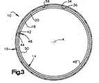
図2を参照すると、拡張可能な支持部材16は管状であり、第1末端22から第2末端24へ軸方向に伸びる。図1に示す拡張可能支持部材16は、複数の支持ビーム26と、軸方向に伸びる複数の支持ロッド27を含む、メッシュ構造である。 Referring to FIG. 2, the
各支持ビーム26は、全体として正弦波の形態を持つ。各支持ビーム26の波長は、隣接する支持ビームの波長と同一であるか、ほぼ同一である。円周方向に隣接する支持ビーム26は、互いに180°位相がずれている。接続バー28(図1)が、各支持ビーム26の頂点30を、隣接する支持ビームと連接した基底32(図1)に接続する。各支持ビーム26の振幅(または高さ)は、全数の支持ビームが、拡張可能支持部材16の円周を形成するように設計される。 Each
軸方向に伸びる支持ロッド27はそれぞれ軸Aに平行に伸びる。支持ロッド27は、拡張可能支持部材16にさらに新たな補強を付け加える。装置10の一つの実施態様は、拡張可能支持部材16の円周上に互いに等距離で隔てられた、8本の支持ロッド27を含む。図1に示される実施態様では、隣接する支持ロッド27の間に、2本の支持ビーム26が配される。 The support rods 27 extending in the axial direction extend in parallel to the axis A, respectively. The support rod 27 adds additional reinforcement to the
拡張可能支持部材16はまた、複数のアイレット29を含む。図1にはその内の4個が示される。各アイレット29は、支持ロッド27の1つから伸びる。図1に描かれるアイレット29は円形であるが、他の形態を用いてもよい。アイレット29は、1層の生物組織14を外部支持部材16に縫い付けるための手段を提供する。 The
拡張可能支持部材16は、拡張可能な金属、例えば、ニチノールから形成される。それとは別に、拡張可能部材は、織布層、例えば、Dacron(登録商標)、またはプラスチック材料、例えば、ポリテトラフロオロエチレン(PTFE)から形成されてもよい。 The
拡張可能支持部材16は、外表面34および内表面36を含む(図2)。外表面34は全体として円筒形であり、軸Aに沿って軸方向に伸びる。内表面36も全体として円筒形であり、外表面34と同軸性である。 The
それとは別に、拡張可能支持部材16は、拡張が可能であって、内表面および外表面36および34をそれぞれ定めるものであれば、任意の既知のステント構造を含んでもよい。装置10は、円形断面形状を持つ円筒形として描かれているが、装置の断面形状は、別に、楕円形、多角形、または円錐形であってもよい。 Alternatively, the
図4a-4fは、本発明の装置10を形成する方法を示す。本方法は、図4aにおいて、ダウエル38と、固定されて四角形に裁断された1層の生物組織14から始まる。ダウエル38は、ガラスから形成される。図4aに描かれるダウエル38は、円筒形で、円形断面の外面40を有する。それとは別に、ダウエル38は円錐形であってもよい。ダウエル38の外面40の円周は、生物組織14の幅に等しい。生物組織14の幅は、第1側面42と第2側面44の間の距離と定義される。図4aは、生物組織14が、ダウエル38の周囲を包みこむ、または巻きつけられるところを示す。 4a-4f illustrate a method of forming the
図4bは、生物組織14がダウエル38の周囲に完全に巻きつけられたところを示す。ダウエル38の周囲に完全に巻きつけられると、生物組織14の第1側面42は、生物組織14の第2側面44に対し、重複せずに、当接する。第1側面42と第2側面44の合致する場所には、軸方向に伸びるシーム46が定義される。シーム46は、生物組織14の軸長に沿って伸びる。生物組織14の軸長は、第1軸端58と第2軸端60の間の距離と定義される。 FIG. 4 b shows the
第1側面42は、第2側面44に当接するが、その当接は、生物組織14の内層18の内面50(図1−3)によって定められる、装置10の内面48(図1−3)が滑らかで、連続的で、途切れがないように行われる。装置10の内面48は、もしも生物組織14が重複したならば生じたであろう突出部または不規則部を持たないので、シーム46における血栓形成および血小板堆積は抑制される。生物組織14の第1および第2側面42と44とが当接することによって得られるもう一つの利点は、装置10の内面48が滑らかで、連続的で、かつ途切れがないために、装置の中で渦流が形成されないことである。 The
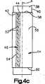
図4cでは、生物組織14の第1側面42が、生物組織14の第2側面44に、縫合52によって付着される。縫合52は、生物組織14を貫いて放射方向内側に伸び、全体として、第1および第2側面42および44の隣接領域の間を円周方向に伸びる。生物組織14は、縫合52が所定の場所に縫いこまれる間は、ダウエル38の上に留まる。1層の生物糊54を、生物組織14の外面56のシーム46の上に設けてもよい。生物糊54は、装置10の内面48が滑らかで、連続的で、途切れがない状態を維持することを確保するのに役立つ。生物糊54はまた、シーム46を通じる漏洩を阻止するようにシーム46を完全に密封することを助ける。 In FIG. 4 c, the
図4dは、拡張可能支持部材16が、生物組織14の上に設置されるところを示す。拡張可能支持部材16は、生物組織14のための外部支持体を形成する。拡張可能支持部材16は、装置10の、放射方向に最外側の成分を形成する。装置10の放射方向に最内側の成分は、1層の生物組織14の漿膜層18によって形成される。 FIG. 4 d shows the
拡張可能支持部材16を生物組織14の上に設置するために、拡張可能支持部材16は拡張される。拡張可能支持部材16を拡張するためには、任意の既知の方法、例えば、拡張可能支持部材の加熱またはバルーン膨張を用いてもよい。ダウエル38、および、ダウエル38の上に保持される生物組織14が、図4dに示すように、拡張可能支持部材16の第1末端22の中に挿入される。拡張可能支持部材16およびダウエル38は互いに動かされ、最終的には、等量の生物組織14が、拡張可能支持部材16の第1および第2末端22および24の両方から軸方向に外側へ伸びるに至る。 In order to place the
続いて、拡張可能支持部材16は、該拡張可能支持部材16の内面36が、生物組織14の外面56の円周に渡って等しく生物組織14の外面56に嵌合するまで、縮小される。次に、生物組織14は、拡張可能支持部材16に付着される。生物組織14を拡張可能支持部材16に付着させるには、縫合(図示せず)を用いることが好ましい。各縫合糸は生物組織14を貫いて伸び、縫合糸の一部は、拡張可能支持部材16のアイレット29の内の一つに通される。次に、縫合糸は、拡張可能支持部材16の外側で、それぞれのアイレット29の周囲に結ばれる。縫合糸は、生物組織14を、拡張可能支持部材16の内面36に保持する。縫合は、血流と縫合との相互作用から渦流が生じることのないよう十分小さい。それとは別に、生物組織14の外面56は、拡張可能支持部材16の内面36に対して、生物糊を用いて糊づけされてもよい。拡張可能支持部材16に生物組織14を付着するために生物糊を用いる場合、支持ビーム26および支持ロッド27は、生物組織14に接着するのに十分なほど大きい内表面積を持っていなければならない。 Subsequently, the
生物組織14が拡張可能部材16に付着した後、図4eに示すように、生物組織14の第1および第2軸末端58および60は、それぞれ、拡張可能支持部材16の第1および第2末端22および24の上に折り返される。生物組織14の第1軸末端58は、引き伸ばされて、拡張可能支持部材16の第1末端22の上に折り返されて、第1折り返し部分62を形成する。次に、第1折り返し部分62は、拡張可能支持部材16の外面34に縫合(図示せず)によって付着される。生物組織14の第2軸末端60は、引き伸ばされて、拡張可能支持部材16の第2末端24の上に折り返されて、第2折り返し部分64を形成する。第2折り返し部分64も、拡張可能支持部材16に縫合(図示せず)によって付着される。 After the
ダウエル38を含む装置10は、患者に埋め込む時期が来るまで滅菌環境に保存される。装置10は、生物学的溶液に浸し、滅菌性の、真空パック容器(図示せず)中に保存するのが好ましい。それとは別に、ダウエル38は、装置を保存する前に装置10から取り去ってもよい。図4fは、装置10からダウエル38が取り去られるところを示す。ダウエル38および装置10は、装置10の内側からのダウエル38の抜去をやり易くするために、生物学的溶液または固定液中に置かれることが好ましい。この溶液は、ダウエル38および生物組織14を十分に潤滑するので、ダウエルは、生物組織14を破ったり傷めることなく、装置10から抜去される。そのため、装置10の内面48は、滑らかで、連続し、途切れがない状態を持続する。それとは別に、装置10を拡張し、拡張した装置10からダウエル38を抜去してもよい。 The
図5は、血管12の中に埋め込まれた本発明の装置10を示す。血管12は、外面66と内面68を含む。血管12の内面68は、血流の方向を決める導管を形成する。装置10は、従来技術で既知の方法を用いて血管12の中まで送られて配置される。装置10が、血管12の所望の位置に配置されたならば、拡張可能支持部材16が、バルーン(図示せず)によって、または、従来技術で既知の自己拡張方式によって、拡張される。拡張可能支持部材16が拡張すると、装置10の第1末端70は血管12に嵌合するが、その嵌合によって、第1折り返し部分62と、血管12の内面68の間に締まり嵌めが形成される。同様に、装置10の第2末端72は血管12に嵌合するが、その嵌合によって、第2折り返し部分64と、血管12の内面68の間に締まり嵌めが形成される。締まり嵌めはまた、拡張可能支持部材16と血管12の内面68との間にも、第1および第2末端70および72の間に伸びる装置10の軸長に沿って形成される。拡張可能支持部材16と血管12の間の締まり嵌めに加えて、拡張可能支持部材16を血管12に固定するために縫合をさらに用いてもよい。 FIG. 5 shows the
装置10が、上述のように、血管12の内面68に嵌合し、接着すると、漿膜の内層18が、第1および第2折り返し部分62および64における最外側面を形成する。この内層18は、通常の組織治癒方式に従って血管12の内面68に接着し、炎症組織の進入を防ぐ。そのため、第1および第2折り返し部分62および64における内層18の漿膜と、血管12の内面68との間の接着は、狭窄または閉塞の再発を阻止する。さらに、第1および第2折り返し部分62および64における内層18の漿膜と、血管12の内面68との間の治癒的接着は、筋膜層20と血管12の内面68との間の接着よりも速やかに形成される。 When the
血管12に埋め込まれた場合、生物組織14の内面50によって形成される導管は、血管12の内面68と、流体に関して一体である。血管12の内面68と、生物組織14の内面50との間の移行部はきわめて滑らかであり、そのため血栓形成および血小板堆積は抑制され、血流は装置10を通過する際にも制限されない。拡張可能支持部材16は、装置10を通過する血流によって引き起こされる内圧に抗する十分な支持を与え、さらに、血管の放射方向の圧潰も抑制する。 When implanted in the
図6は、本発明に従って構築される装置10aの第2実施態様の長軸断面図である。図6に示す実施態様の構造は、図1−3の構造と近似するが、接尾語”a”をつけた同じ参照数字を持つ。装置10aは、図6の実施態様の1層の生物組織14aは1層の漿膜18aしか含まないことを除いて、図1−3の装置10と同じである。 FIG. 6 is a longitudinal cross-sectional view of a second embodiment of an apparatus 10a constructed in accordance with the present invention. The structure of the embodiment shown in FIG. 6 is similar to the structure of FIGS. 1-3, but has the same reference numerals with the suffix “a”. Device 10a is the same as
生物組織層14aは、漿膜層18aしか含まないように採取される。漿膜層18aだけを採取する方法は、従来技術で既知である。 The biological tissue layer 14a is collected so as to include only the serosal layer 18a. Methods for collecting only the serosa layer 18a are known in the prior art.
装置10aの組立は、図4a−4fに示す装置10の組立と同じである。1層の生物組織14aは、所望の形に裁断されると、それぞれ、第1および第2側面42aおよび44a、および第1および第2軸末端58aおよび60aを含む。 The assembly of device 10a is the same as the assembly of
組み立てられた装置は、第1および第2側面42aおよび44aの当接によって形成されるシーム46aを含む。組立装置10aはまた、第1および第2折り返し部分62aおよび64aを含む。第1折り返し部分62aは、生物組織層14aの第1軸末端58aを、拡張可能支持部材16aの第1末端22aの上に折り返すことによって形成される。第2折り返し部分64aは、生物組織層14aの第2軸末端60aを、拡張可能支持部材16aの第2末端24aの上に折り返すことによって形成される。 The assembled device includes a seam 46a formed by abutment of the first and second side surfaces 42a and 44a. The assembly apparatus 10a also includes first and second folded portions 62a and 64a. The first folded portion 62a is formed by folding the first axial end 58a of the biological tissue layer 14a over the first end 22a of the expandable support member 16a. The second folded portion 64a is formed by folding the second axial end 60a of the biological tissue layer 14a over the second end 24a of the expandable support member 16a.
組立られた装置10aの内面48aは、漿膜層18aの内面50aによって定められる。装置10aの内面148aは滑らかで、連続しており、途切れがない。装置10aの、滑らかで、連続的で、途切れのない内面48aは、血栓形成および血小板堆積を抑える。 The inner surface 48a of the assembled device 10a is defined by the inner surface 50a of the serosa layer 18a. The inner surface 148a of the device 10a is smooth, continuous and uninterrupted. The smooth, continuous, uninterrupted inner surface 48a of the device 10a suppresses thrombus formation and platelet deposition.
図7は、本発明の第3実施態様に従って構築される装置10bの長軸断面図である。図7に示す実施態様の構造は、図1−3の構造と近似するが、接尾語”b”をつけた同じ参照数字を持つ。 FIG. 7 is a longitudinal cross-sectional view of an
図7に示す装置10bは、1層の生物組織14bおよび拡張可能支持部材16bを含む。生物組織層14bは、漿膜層18bおよび連結する筋膜層20bを含む。拡張可能支持部材16bは、図1に示したものと同様の構造を持つ。生物組織層14bは、装置10bの最内側成分を形成する。 The
生物組織層14bは、生物組織14bの第1および第2側面42bおよび44bを、シーム46bにおいて当接することによって、管状部分を形成する。第1および第2側面42bおよび44bをシーム46bで縫い合わせ、生物組織14bの外面56bに生物糊(図示せず)を塗布するのが好ましい。
生物組織層14bの外面56bは、拡張可能支持部材16bの内面36bに付着される。拡張可能支持部材16bは生物組織14bの上に置かれるが、その際、拡張可能支持部材16bの第1および第2末端22bおよび24bから、等量の生物組織14bが伸びるように行われる。生物組織14bの第1および第2軸末端58bおよび60bは、図1−3の実施態様に関して前述したように拡張可能支持部材16bの上に折り返される代わりに、拡張可能支持部材16bの第1および第2末端22bおよび24bを超えて、軸方向に伸びる。従って、装置10bを組み立てる際は、工程4eに示した工程は省略される。 The
組織14bの第1および第2軸末端58bおよび60bは、患者の血管に埋め込まれると、拡張可能支持部材16の拡張によって血管の内面と嵌合し、接着する。生物組織14bの第1および第2軸末端58bおよび60bの、拡張可能支持部材16bの第1および第2末端22bおよび24bを超えた軸方向の伸長によって、生物組織の第1および第2軸末端を血管の内面に直接縫合することが可能になる。 The first and second axial ends 58b and 60b of the
図8は、本発明に従って構築される装置10cの第4実施態様の長軸断面図である。図8に示す実施態様の構造は、図7の構造と近似するが、接尾語”b”の代わりに接尾語”c”をつけた同じ参照数字を持つ。装置10cは、図8の実施態様の1層の生物組織14cは1層の漿膜18cしか含まないことを除いて、図7の装置10bと同じである。 FIG. 8 is a longitudinal cross-sectional view of a fourth embodiment of a
装置10cの組立は、装置10bの組立と同じである。1層の生物組織14cは、所望の形に裁断されると、それぞれ、第1および第2側面42cおよび44c、および第1および第2軸末端58cおよび60cを含む。 The assembly of the
組み立てられた装置は、第1および第2側面42cおよび44cの当接によって形成されるシーム46cを含む。組み立てられた装置10cの内面48cは、漿膜層18cの内面50cによって定められる。装置10cの内面48cは滑らかで、連続しており、途切れがない。装置10cの、滑らかで、連続的で、途切れのない内面48cは、血栓形成および血小板堆積を抑える。 The assembled device includes a
図9は、本発明に従って構築される装置10dの第5実施態様の長軸断面図である。図9に示す実施態様の構造は、図7の構造と近似するが、接尾語”b”の代わりに接尾語”d”をつけた同じ参照数字を持つ。 FIG. 9 is a longitudinal cross-sectional view of a fifth embodiment of a
図9の装置10dも循環器移植片である。装置10dは、漿膜の内層18dおよび、該漿膜に連結する筋膜の外層20dを含む、1層の生物組織14dを含む。生物組織層14dは四角く、それぞれ、第1および第2側面42dおよび44d、および第1および第2軸末端58dおよび60dを含む。漿膜の内層18dは、内面50dを含む。筋膜の外層20dは、外面56dを含む。 The
図9に描かれる装置10dは円筒形で、生物組織層14dによって形成される。生物組織層14dの第1および第2側面42dおよび44dは当接され、互いに固定されてシーム46dを定める。縫合52dが、第1および第2側面42dおよび44dをシーム46dにおいて付着する。シーム46d上において、外層20dの外面56dに対して1層の生物糊(図示せず)が塗布される。生物糊は、シームを通じる漏洩を阻止するようにシーム46dを完全に密封することを助ける。 The
装置10dを形成するためには、図4aから4cに示した、図1−3の装置10に関連して詳細に論じた工程に従う。図4cに示した工程の後、装置10dは、患者に埋め込む時期が来るまで滅菌環境に保存される。患者への埋め込み前に、ダウエルは装置から抜去される。 To
外層20dの外面56dは、装置10dの最外側成分を形成する。漿膜から成る内層18dの内面50dが、装置10dの最内側成分を形成する。内層18dの内面50dは滑らかで、連続しており、途切れがない。そのため、装置10dの内面48dは、滑らかで、連続的で、途切れがなく、血栓形成および血小板堆積を抑える。 The
患者の中に外科的に埋め込まれる場合、装置10dは縫合によって付着される。例えば、血管の中に使用される場合、装置10dは、血管の内面に縫合される。そのため、内層18dの連続的で、途切れのない内面50dは、血管の内面と、流体に関して一体である。 When surgically implanted in a patient, the
装置10dは、支持構造を含まないので、それの付着される血管の形に対して適応、または合致する。従って、血管の内面が楕円の断面形を持つ場合には、装置10dは、血管の内面に付着されると、楕円の断面形を持つ。 Since
図10は、本発明に従って構築される装置10eの第6実施態様の長軸断面図である。図10に示す実施態様の構造は、図9の構造と近似するが、接尾語”d”の代わりに接尾語”e”をつけた同じ参照数字を持つ。装置10eは、図10の実施態様の1層の生物組織14eは1層の漿膜18eしか含まないことを除いて、図9の装置10dと同じである。 FIG. 10 is a longitudinal cross-sectional view of a sixth embodiment of a device 10e constructed in accordance with the present invention. The structure of the embodiment shown in FIG. 10 is similar to that of FIG. 9 but has the same reference numerals with the suffix “e” instead of the suffix “d”. Device 10e is the same as
装置10eの組立は、装置10eの組立と同じである。1層の生物組織14eは、所望の形に裁断されると、それぞれ、第1および第2側面42eおよび44e、および第1および第2軸末端58eおよび60eを含む。 The assembly of the device 10e is the same as the assembly of the device 10e. A layer of
組み立てられた装置は、第1および第2側面42eおよび44eの当接によって形成されるシーム46eを含む。組み立てられた装置10eの内面48eは、漿膜層18eの内面50eによって定められる。装置10eの内面48eは滑らかで、連続しており、途切れがない。装置10eの、滑らかで、連続的で、途切れのない内面48eは、血栓形成および血小板堆積を抑える。 The assembled device includes a seam 46e formed by abutment of the first and second side surfaces 42e and 44e. The
図11は、本発明に従って構築される装置100の第7実施態様の斜視図を示す。図11の装置100は、血管の一部、または、人体の循環器系内の他の膜を修復するためのパッチである。 FIG. 11 shows a perspective view of a seventh embodiment of an
パッチ100は、1層の生物組織102および外部支持部材104を含む。生物組織層102は、漿膜層106および、連結する筋膜層108を含む。漿膜層106は、生物組織102の内膜(図示せず)を形成し、連結する筋膜108は、生物組織102の外面110を形成する。生物組織層102は、四角形として描かれているが、所望の任意の形態を取ってよい。 The
外部支持部材104は、生物組織102と同じ形を持つが、サイズがやや小さい。外部支持部材104は、血管の内面または外面のような曲面に適合するよう、図11に例示するように、曲面状のプロフィールを持ってもよい。 The
図11の外部支持部材104は四角形で、外部フレーム112と内部支持ビーム114を含む。外部フレーム112は、外部支持部材104の形状を定め、生物組織102の辺縁近傍を支える。外部支持部材104の内部支持ビーム114は、生物組織102の内部部分を支える。アイレット118が設けられて、生物組織102を外部支持部材104に付着する際に、縫合糸(図示せず)がそこに通されてもよい。 The
生物組織102の外面110は、外部支持部材104に付着される。生物組織102は、外部支持部材104に縫合されるのが好ましい。生物組織102の辺縁部は、外部支持部材104から外側に伸長する。それとは別に、生物組織102の辺縁部分は、外部支持部材104の外部フレーム112の上に折り返されてもよい。 The
血管内に埋め込まれる場合、パッチ100の外部支持部材104の外面116は、動脈瘤、または、血管の脆弱部分の上に置かれる。外部支持部材104のサイズは、動脈瘤、または血管の脆弱部分よりも大きいことが好ましく、それによって、外部支持部材104の外部フレーム112が、血管内面の健常部分に接触する。次に、生物組織102の外周が、血管の内面に、好ましくは縫合によって、付着される。別態様として、パッチ100は、血管の外面に置かれてもよいし、あるいは、循環器系の別の膜の上に使用されてもよい。 When implanted within a blood vessel, the
図12は、本発明に従って構築される装置100aの第8実施態様の図である。図12に示す実施態様の構造は、図11の構造と近似するが、接尾語”a”をつけた同じ参照数字を持つ。 FIG. 12 is a diagram of an eighth embodiment of an apparatus 100a constructed in accordance with the present invention. The structure of the embodiment shown in FIG. 12 is similar to that of FIG. 11 but has the same reference numerals with the suffix “a”.
図12の装置100aも、血管の一部、または、人体の循環器系内の他の膜を修復するためのパッチである。パッチ100aは1層の生物組織102aを含む。図12のパッチ100aは、図11に示した外部支持部材104のような支持構造を含まない。 The device 100a of FIG. 12 is also a patch for repairing a portion of a blood vessel or other membrane in the human circulatory system. Patch 100a includes a layer of biological tissue 102a. The patch 100a in FIG. 12 does not include a support structure like the
生物組織層102aは、漿膜層106aおよび、連結する筋膜層108aを含む。漿膜層106aは、生物組織102aの内膜(図示せず)を形成し、連結する筋膜108aは、生物組織102aの外面110aを形成する。生物組織102aの内面は滑らかで、連続しており、途切れがない。生物組織層102aは、四角形として描かれているが、所望の任意の形態を取ってよい。 The biological tissue layer 102a includes a serosal layer 106a and a connecting fascial layer 108a. The serosa layer 106a forms the inner membrane (not shown) of the biological tissue 102a, and the connecting fascia 108a forms the outer surface 110a of the biological tissue 102a. The inner surface of the biological tissue 102a is smooth and continuous, and is not interrupted. The biological tissue layer 102a is depicted as a square, but may take any desired form.
血管内に埋め込まれる場合、生物組織層102aの、連結する筋膜108aの外面110aは、動脈瘤、または、血管の脆弱部分の上に置かれる。次に、生物組織102aは、血管の内面に、好ましくは縫合によって、付着される。パッチ100aは構造的支持体を含まないので、パッチ100aは、それが付着される血管または膜の形状に容易に適応し、パッチ100aと血管または膜との間に十分な接触面積を確保する。別態様として、パッチ100aは、血管の外面に置かれてもよいし、あるいは、循環器系の別の膜の上に使用されてもよい。 When implanted within a blood vessel, the outer surface 110a of the connecting fascia 108a of the biological tissue layer 102a is placed over the aneurysm or fragile portion of the blood vessel. The biological tissue 102a is then attached to the inner surface of the blood vessel, preferably by suturing. Since patch 100a does not include a structural support, patch 100a easily adapts to the shape of the blood vessel or membrane to which it is attached and ensures sufficient contact area between patch 100a and the blood vessel or membrane. Alternatively, the patch 100a may be placed on the outer surface of the blood vessel or used on another membrane of the circulatory system.
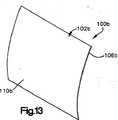
図13は、本発明に従って構築される装置100bの第9実施態様の斜視図である。図13に示す実施態様の構造は、図12の構造と近似するが、接尾語”a”の代わりに接尾語”b”をつけた同じ参照数字を持つ。装置100bは、図13の実施態様の1層の生物組織102bは1層の漿膜106bしか含まないことを除いて、図12の装置100aと同じである。 FIG. 13 is a perspective view of a ninth embodiment of an
生物組織層102bの外面110bは、漿膜層106bの外面によって形成される。生物組織の内面(図示せず)は、漿膜層106bの内面によって形成され、滑らかで、連続しており、途切れがない。 The
以上の本発明についての記載から、当業者であれば、改良点、変更点、および修正点に気づくであろう。例えば、本明細書に記載される方法によって固定される生物組織14は、様々な用途、例えば、心臓弁や静脈弁のようなその他の血管弁、動脈のパッチやその他の心臓成分、および血管の置換または移植などを含む用途に、ただしこれらに限定されないが、使用が可能であることが思量される。当業者の熟練の範囲内にある、このような改良点、変更点、および修正点は、本願の特許請求の範囲によって包含されるものであることが意図される。 From the above description of the invention, those skilled in the art will perceive improvements, changes and modifications. For example,
Claims (6)
Translated fromJapanese(イ)採取された生物組織の少なくとも1層を整形すること、
(ロ)整形された該生物組織を少なくとも部分的に架橋すること、
(ハ)少なくとも部分的に架橋された該生物組織を滅菌すること、および、
(ニ)滅菌された該生物組織の中のプリオンを不活性化すること、
を含み、
工程(イ)、(ロ)、(ハ)、(ニ)の順番で行うことを特徴とする方法。A method for preparing a fixed biological tissue comprising:
(B) shapingat least one layer of the collected biological tissue;
(B) at least partially cross-linking the shaped biological tissue;
(C) sterilizing the biological tissue that is at least partially crosslinked; and
(D) inactivating prions in the sterilized biological tissue;
Only including,
A methodcharacterized in that it is carried out in the order of steps (a), (b), (c), and (d) .
Applications Claiming Priority (2)
| Application Number | Priority Date | Filing Date | Title |
|---|---|---|---|
| US11/029,687US7559953B2 (en) | 2001-07-19 | 2005-01-05 | Method for fixing tissue |
| PCT/US2005/043312WO2006073626A2 (en) | 2005-01-05 | 2005-12-01 | Method for fixing tissue |
Publications (2)
| Publication Number | Publication Date |
|---|---|
| JP2008526359A JP2008526359A (en) | 2008-07-24 |
| JP4499163B2true JP4499163B2 (en) | 2010-07-07 |
Family
ID=36581767
Family Applications (1)
| Application Number | Title | Priority Date | Filing Date |
|---|---|---|---|
| JP2007550367AExpired - Fee RelatedJP4499163B2 (en) | 2005-01-05 | 2005-12-01 | Tissue fixation method |
Country Status (8)
| Country | Link |
|---|---|
| EP (1) | EP1833524B1 (en) |
| JP (1) | JP4499163B2 (en) |
| AT (1) | ATE474607T1 (en) |
| AU (1) | AU2005323327B2 (en) |
| BR (1) | BRPI0519298A2 (en) |
| CA (1) | CA2592773C (en) |
| DE (1) | DE602005022491D1 (en) |
| WO (1) | WO2006073626A2 (en) |
Families Citing this family (115)
| Publication number | Priority date | Publication date | Assignee | Title |
|---|---|---|---|---|
| US8728154B2 (en) | 2007-08-24 | 2014-05-20 | St. Jude Medical, Inc. | Prosthetic aortic heart valves |
| EP3443938B1 (en) | 2007-09-26 | 2024-01-24 | St. Jude Medical, LLC | Collapsible prosthetic heart valves |
| US9532868B2 (en) | 2007-09-28 | 2017-01-03 | St. Jude Medical, Inc. | Collapsible-expandable prosthetic heart valves with structures for clamping native tissue |
| WO2009045334A1 (en) | 2007-09-28 | 2009-04-09 | St. Jude Medical, Inc. | Collapsible/expandable prosthetic heart valves with native calcified leaflet retention features |
| US8163004B2 (en)* | 2008-02-18 | 2012-04-24 | Aga Medical Corporation | Stent graft for reinforcement of vascular abnormalities and associated method |
| EP2815724B2 (en) | 2008-07-15 | 2024-03-13 | St. Jude Medical, Inc. | Collapsible and re-expandable prosthetic heart valve cuff designs and complementary technological applications |
| AU2010218384B2 (en) | 2009-02-27 | 2014-11-20 | St. Jude Medical, Inc. | Stent features for collapsible prosthetic heart valves |
| US9795476B2 (en) | 2010-06-17 | 2017-10-24 | St. Jude Medical, Llc | Collapsible heart valve with angled frame |
| US9039759B2 (en) | 2010-08-24 | 2015-05-26 | St. Jude Medical, Cardiology Division, Inc. | Repositioning of prosthetic heart valve and deployment |
| US8814931B2 (en) | 2010-08-24 | 2014-08-26 | St. Jude Medical, Cardiology Division, Inc. | Staged deployment devices and methods for transcatheter heart valve delivery systems |
| WO2012036741A2 (en) | 2010-09-17 | 2012-03-22 | St. Jude Medical, Cardiology Division, Inc. | Staged deployment devices and methods for transcatheter heart valve delivery |
| USD654169S1 (en) | 2010-09-20 | 2012-02-14 | St. Jude Medical Inc. | Forked ends |
| USD660433S1 (en) | 2010-09-20 | 2012-05-22 | St. Jude Medical, Inc. | Surgical stent assembly |
| USD653341S1 (en) | 2010-09-20 | 2012-01-31 | St. Jude Medical, Inc. | Surgical stent |
| USD660432S1 (en) | 2010-09-20 | 2012-05-22 | St. Jude Medical, Inc. | Commissure point |
| USD660967S1 (en) | 2010-09-20 | 2012-05-29 | St. Jude Medical, Inc. | Surgical stent |
| USD653342S1 (en) | 2010-09-20 | 2012-01-31 | St. Jude Medical, Inc. | Stent connections |
| USD654170S1 (en) | 2010-09-20 | 2012-02-14 | St. Jude Medical, Inc. | Stent connections |
| USD652926S1 (en) | 2010-09-20 | 2012-01-24 | St. Jude Medical, Inc. | Forked end |
| USD652927S1 (en) | 2010-09-20 | 2012-01-24 | St. Jude Medical, Inc. | Surgical stent |
| USD653343S1 (en) | 2010-09-20 | 2012-01-31 | St. Jude Medical, Inc. | Surgical cuff |
| AU2011306028B2 (en) | 2010-09-20 | 2014-07-17 | St. Jude Medical, Cardiology Division, Inc. | Valve leaflet attachment in collapsible prosthetic valves |
| USD684692S1 (en) | 2010-09-20 | 2013-06-18 | St. Jude Medical, Inc. | Forked ends |
| USD648854S1 (en) | 2010-09-20 | 2011-11-15 | St. Jude Medical, Inc. | Commissure points |
| US9717593B2 (en) | 2011-02-01 | 2017-08-01 | St. Jude Medical, Cardiology Division, Inc. | Leaflet suturing to commissure points for prosthetic heart valve |
| US9060860B2 (en) | 2011-08-18 | 2015-06-23 | St. Jude Medical, Cardiology Division, Inc. | Devices and methods for transcatheter heart valve delivery |
| JP6184963B2 (en)* | 2011-10-05 | 2017-08-23 | ボストン サイエンティフィック サイムド,インコーポレイテッドBoston Scientific Scimed,Inc. | Thin seal material for replacement heart valve and method of forming the same |
| US9289292B2 (en) | 2012-06-28 | 2016-03-22 | St. Jude Medical, Cardiology Division, Inc. | Valve cuff support |
| US9554902B2 (en) | 2012-06-28 | 2017-01-31 | St. Jude Medical, Cardiology Division, Inc. | Leaflet in configuration for function in various shapes and sizes |
| US9241791B2 (en) | 2012-06-29 | 2016-01-26 | St. Jude Medical, Cardiology Division, Inc. | Valve assembly for crimp profile |
| US20140005776A1 (en) | 2012-06-29 | 2014-01-02 | St. Jude Medical, Cardiology Division, Inc. | Leaflet attachment for function in various shapes and sizes |
| US9615920B2 (en) | 2012-06-29 | 2017-04-11 | St. Jude Medical, Cardiology Divisions, Inc. | Commissure attachment feature for prosthetic heart valve |
| US10004597B2 (en) | 2012-07-03 | 2018-06-26 | St. Jude Medical, Cardiology Division, Inc. | Stent and implantable valve incorporating same |
| US9808342B2 (en) | 2012-07-03 | 2017-11-07 | St. Jude Medical, Cardiology Division, Inc. | Balloon sizing device and method of positioning a prosthetic heart valve |
| US10524909B2 (en) | 2012-10-12 | 2020-01-07 | St. Jude Medical, Cardiology Division, Inc. | Retaining cage to permit resheathing of a tavi aortic-first transapical system |
| US9801721B2 (en) | 2012-10-12 | 2017-10-31 | St. Jude Medical, Cardiology Division, Inc. | Sizing device and method of positioning a prosthetic heart valve |
| US9186238B2 (en) | 2013-01-29 | 2015-11-17 | St. Jude Medical, Cardiology Division, Inc. | Aortic great vessel protection |
| US9655719B2 (en) | 2013-01-29 | 2017-05-23 | St. Jude Medical, Cardiology Division, Inc. | Surgical heart valve flexible stent frame stiffener |
| US9314163B2 (en) | 2013-01-29 | 2016-04-19 | St. Jude Medical, Cardiology Division, Inc. | Tissue sensing device for sutureless valve selection |
| US9901470B2 (en) | 2013-03-01 | 2018-02-27 | St. Jude Medical, Cardiology Division, Inc. | Methods of repositioning a transcatheter heart valve after full deployment |
| US9844435B2 (en) | 2013-03-01 | 2017-12-19 | St. Jude Medical, Cardiology Division, Inc. | Transapical mitral valve replacement |
| US9480563B2 (en) | 2013-03-08 | 2016-11-01 | St. Jude Medical, Cardiology Division, Inc. | Valve holder with leaflet protection |
| US10271949B2 (en) | 2013-03-12 | 2019-04-30 | St. Jude Medical, Cardiology Division, Inc. | Paravalvular leak occlusion device for self-expanding heart valves |
| US9398951B2 (en) | 2013-03-12 | 2016-07-26 | St. Jude Medical, Cardiology Division, Inc. | Self-actuating sealing portions for paravalvular leak protection |
| US10314698B2 (en) | 2013-03-12 | 2019-06-11 | St. Jude Medical, Cardiology Division, Inc. | Thermally-activated biocompatible foam occlusion device for self-expanding heart valves |
| EP2967849B1 (en) | 2013-03-12 | 2025-08-13 | St. Jude Medical, Cardiology Division, Inc. | Self-actuating sealing portions for paravalvular leak protection |
| US9339274B2 (en) | 2013-03-12 | 2016-05-17 | St. Jude Medical, Cardiology Division, Inc. | Paravalvular leak occlusion device for self-expanding heart valves |
| US9636222B2 (en) | 2013-03-12 | 2017-05-02 | St. Jude Medical, Cardiology Division, Inc. | Paravalvular leak protection |
| US9326856B2 (en) | 2013-03-14 | 2016-05-03 | St. Jude Medical, Cardiology Division, Inc. | Cuff configurations for prosthetic heart valve |
| US9131982B2 (en) | 2013-03-14 | 2015-09-15 | St. Jude Medical, Cardiology Division, Inc. | Mediguide-enabled renal denervation system for ensuring wall contact and mapping lesion locations |
| WO2014204807A1 (en) | 2013-06-19 | 2014-12-24 | Aga Medical Corporation | Collapsible valve having paravalvular leak protection |
| US9668856B2 (en) | 2013-06-26 | 2017-06-06 | St. Jude Medical, Cardiology Division, Inc. | Puckering seal for reduced paravalvular leakage |
| USD730521S1 (en) | 2013-09-04 | 2015-05-26 | St. Jude Medical, Cardiology Division, Inc. | Stent with commissure attachments |
| USD730520S1 (en) | 2013-09-04 | 2015-05-26 | St. Jude Medical, Cardiology Division, Inc. | Stent with commissure attachments |
| US9867611B2 (en) | 2013-09-05 | 2018-01-16 | St. Jude Medical, Cardiology Division, Inc. | Anchoring studs for transcatheter valve implantation |
| US10117742B2 (en) | 2013-09-12 | 2018-11-06 | St. Jude Medical, Cardiology Division, Inc. | Stent designs for prosthetic heart valves |
| EP2870946B1 (en) | 2013-11-06 | 2018-10-31 | St. Jude Medical, Cardiology Division, Inc. | Paravalvular leak sealing mechanism |
| US9913715B2 (en) | 2013-11-06 | 2018-03-13 | St. Jude Medical, Cardiology Division, Inc. | Paravalvular leak sealing mechanism |
| EP4176844B1 (en) | 2013-11-06 | 2025-08-20 | St. Jude Medical, Cardiology Division, Inc. | Reduced profile prosthetic heart valve |
| WO2015073287A1 (en) | 2013-11-12 | 2015-05-21 | St. Jude Medical, Cardiology Division, Inc. | Pneumatically power-assisted tavi delivery system |
| WO2015077274A1 (en) | 2013-11-19 | 2015-05-28 | St. Jude Medical, Cardiology Division, Inc. | Sealing structures for paravalvular leak protection |
| US10314693B2 (en) | 2013-11-27 | 2019-06-11 | St. Jude Medical, Cardiology Division, Inc. | Cuff stitching reinforcement |
| US9597185B2 (en) | 2013-12-19 | 2017-03-21 | St. Jude Medical, Cardiology Division, Inc. | Leaflet-cuff attachments for prosthetic heart valve |
| US9820852B2 (en) | 2014-01-24 | 2017-11-21 | St. Jude Medical, Cardiology Division, Inc. | Stationary intra-annular halo designs for paravalvular leak (PVL) reduction—active channel filling cuff designs |
| US20150209141A1 (en) | 2014-01-24 | 2015-07-30 | St. Jude Medical, Cardiology Division, Inc. | Stationary intra-annular halo designs for paravalvular leak (pvl) reduction-passive channel filling cuff designs |
| US10292711B2 (en) | 2014-02-07 | 2019-05-21 | St. Jude Medical, Cardiology Division, Inc. | Mitral valve treatment device having left atrial appendage closure |
| US9867556B2 (en) | 2014-02-07 | 2018-01-16 | St. Jude Medical, Cardiology Division, Inc. | System and method for assessing dimensions and eccentricity of valve annulus for trans-catheter valve implantation |
| WO2015126712A1 (en) | 2014-02-18 | 2015-08-27 | St. Jude Medical, Cardiology Division, Inc. | Bowed runners for paravalvular leak protection |
| US9763778B2 (en) | 2014-03-18 | 2017-09-19 | St. Jude Medical, Cardiology Division, Inc. | Aortic insufficiency valve percutaneous valve anchoring |
| US10085834B2 (en) | 2014-03-18 | 2018-10-02 | St. Jude Medical, Cardiology Divsion, Inc. | Mitral valve replacement toggle cell securement |
| US9610157B2 (en) | 2014-03-21 | 2017-04-04 | St. Jude Medical, Cardiology Division, Inc. | Leaflet abrasion mitigation |
| EP3122289A1 (en) | 2014-03-26 | 2017-02-01 | St. Jude Medical, Cardiology Division, Inc. | Transcatheter mitral valve stent frames |
| WO2015152980A1 (en) | 2014-03-31 | 2015-10-08 | St. Jude Medical, Cardiology Division, Inc. | Paravalvular sealing via extended cuff mechanisms |
| EP3131504B1 (en) | 2014-04-14 | 2023-03-15 | St. Jude Medical, Cardiology Division, Inc. | Leaflet abrasion mitigation in prosthetic heart valves |
| ES2795358T3 (en) | 2014-05-16 | 2020-11-23 | St Jude Medical Cardiology Div Inc | Subannular sealing for paravalvular leak protection |
| EP3142604B1 (en) | 2014-05-16 | 2024-01-10 | St. Jude Medical, Cardiology Division, Inc. | Transcatheter valve with paravalvular leak sealing ring |
| US9757230B2 (en) | 2014-05-16 | 2017-09-12 | St. Jude Medical, Cardiology Division, Inc. | Stent assembly for use in prosthetic heart valves |
| WO2015179473A1 (en) | 2014-05-22 | 2015-11-26 | St. Jude Medical, Cardiology Division, Inc. | Stents with anchoring sections |
| EP2954875B1 (en) | 2014-06-10 | 2017-11-15 | St. Jude Medical, Cardiology Division, Inc. | Stent cell bridge for cuff attachment |
| US9737264B2 (en) | 2014-08-18 | 2017-08-22 | St. Jude Medical, Cardiology Division, Inc. | Sensors for prosthetic heart devices |
| WO2016028583A1 (en) | 2014-08-18 | 2016-02-25 | St. Jude Medical, Cardiology Division, Inc. | Sensors for prosthetic heart devices |
| EP3182927B1 (en) | 2014-08-18 | 2024-11-13 | St. Jude Medical, Cardiology Division, Inc. | Prosthetic heart devices having diagnostic capabilities |
| EP3185817A4 (en)* | 2014-08-27 | 2018-07-18 | Amnis Therapeutics Ltd. | Implantable devices comprising graft membranes |
| US10314699B2 (en) | 2015-03-13 | 2019-06-11 | St. Jude Medical, Cardiology Division, Inc. | Recapturable valve-graft combination and related methods |
| EP3273912A1 (en) | 2015-03-23 | 2018-01-31 | St. Jude Medical, Cardiology Division, Inc. | Heart valve repair |
| US9962260B2 (en) | 2015-03-24 | 2018-05-08 | St. Jude Medical, Cardiology Division, Inc. | Prosthetic mitral valve |
| US10070954B2 (en) | 2015-03-24 | 2018-09-11 | St. Jude Medical, Cardiology Division, Inc. | Mitral heart valve replacement |
| US10716672B2 (en) | 2015-04-07 | 2020-07-21 | St. Jude Medical, Cardiology Division, Inc. | System and method for intraprocedural assessment of geometry and compliance of valve annulus for trans-catheter valve implantation |
| EP3307207A1 (en) | 2015-06-12 | 2018-04-18 | St. Jude Medical, Cardiology Division, Inc. | Heart valve repair and replacement |
| US10639149B2 (en) | 2015-07-16 | 2020-05-05 | St. Jude Medical, Cardiology Division, Inc. | Sutureless prosthetic heart valve |
| WO2017027541A1 (en) | 2015-08-12 | 2017-02-16 | St. Jude Medical, Cardiology Division, Inc. | Collapsible heart valve including stents with tapered struts |
| WO2017196909A1 (en) | 2016-05-12 | 2017-11-16 | St. Jude Medical, Cardiology Division, Inc. | Mitral heart valve replacement |
| USD802764S1 (en) | 2016-05-13 | 2017-11-14 | St. Jude Medical, Cardiology Division, Inc. | Surgical stent |
| USD802766S1 (en) | 2016-05-13 | 2017-11-14 | St. Jude Medical, Cardiology Division, Inc. | Surgical stent |
| USD802765S1 (en) | 2016-05-13 | 2017-11-14 | St. Jude Medical, Cardiology Division, Inc. | Surgical stent |
| EP3454785B1 (en) | 2016-05-13 | 2021-11-17 | St. Jude Medical, Cardiology Division, Inc. | Heart valve with stent having varying cell densities |
| US10548722B2 (en) | 2016-08-26 | 2020-02-04 | St. Jude Medical, Cardiology Division, Inc. | Prosthetic heart valve with paravalvular leak mitigation features |
| US10456249B2 (en) | 2016-09-15 | 2019-10-29 | St. Jude Medical, Cardiology Division, Inc. | Prosthetic heart valve with paravalvular leak mitigation features |
| EP3531977B1 (en) | 2016-10-28 | 2024-06-26 | St. Jude Medical, Cardiology Division, Inc. | Prosthetic mitral valve |
| WO2018102525A1 (en) | 2016-12-02 | 2018-06-07 | St. Jude Medical, Cardiology Division, Inc. | Transcatheter delivery system with two modes of actuation |
| WO2018102520A1 (en) | 2016-12-02 | 2018-06-07 | St. Jude Medical, Cardiology Division, Inc. | Transcatheter delivery system with transverse wheel actuation |
| WO2018160790A1 (en) | 2017-03-03 | 2018-09-07 | St. Jude Medical, Cardiology Division, Inc. | Transcatheter mitral valve design |
| USD875935S1 (en) | 2017-05-15 | 2020-02-18 | St. Jude Medical, Cardiology Division, Inc. | Stent having tapered struts |
| USD875250S1 (en) | 2017-05-15 | 2020-02-11 | St. Jude Medical, Cardiology Division, Inc. | Stent having tapered aortic struts |
| WO2018213091A1 (en) | 2017-05-15 | 2018-11-22 | St. Jude Medical, Cardiology Division, Inc. | Transcatheter delivery system with wheel actuation |
| USD889653S1 (en) | 2017-05-15 | 2020-07-07 | St. Jude Medical, Cardiology Division, Inc. | Stent having tapered struts |
| US11382751B2 (en) | 2017-10-24 | 2022-07-12 | St. Jude Medical, Cardiology Division, Inc. | Self-expandable filler for mitigating paravalvular leak |
| US11813413B2 (en) | 2018-03-27 | 2023-11-14 | St. Jude Medical, Cardiology Division, Inc. | Radiopaque outer cuff for transcatheter valve |
| US11234812B2 (en) | 2018-04-18 | 2022-02-01 | St. Jude Medical, Cardiology Division, Inc. | Methods for surgical valve expansion |
| WO2020060828A1 (en) | 2018-09-20 | 2020-03-26 | St. Jude Medical, Cardiology Division, Inc. | Attachment of leaflets to prosthetic heart valve |
| US11364117B2 (en) | 2018-10-15 | 2022-06-21 | St. Jude Medical, Cardiology Division, Inc. | Braid connections for prosthetic heart valves |
| US11471277B2 (en) | 2018-12-10 | 2022-10-18 | St. Jude Medical, Cardiology Division, Inc. | Prosthetic tricuspid valve replacement design |
| EP3902503B1 (en) | 2018-12-26 | 2025-01-29 | St. Jude Medical, Cardiology Division, Inc. | Elevated outer cuff for reducing paravalvular leakage and increasing stent fatigue life |
| US12427018B2 (en) | 2020-05-11 | 2025-09-30 | St. Jude Medical, Cardiology Division, Inc. | Transcatheter mitral valve fixation concepts |
| WO2022015634A1 (en) | 2020-07-15 | 2022-01-20 | Tendyne Holdings, Inc. | Tether attachment for mitral valve |
Family Cites Families (12)
| Publication number | Priority date | Publication date | Assignee | Title |
|---|---|---|---|---|
| US4741699A (en)* | 1983-08-19 | 1988-05-03 | Austenal International, Inc. | Uniformly fluorescing porcelain dental restorations |
| US5480424A (en)* | 1993-11-01 | 1996-01-02 | Cox; James L. | Heart valve replacement using flexible tubes |
| ATE310839T1 (en)* | 1994-04-29 | 2005-12-15 | Scimed Life Systems Inc | STENT WITH COLLAGEN |
| WO1997009006A1 (en)* | 1995-09-01 | 1997-03-13 | Emory University | Endovascular support device and method of use |
| IL139708A0 (en)* | 2000-11-15 | 2002-02-10 | Amiel Gilad | Process of decellularizing biological matrices and acellular biological matrices useful in tissue engineering |
| US6696074B2 (en)* | 2000-12-04 | 2004-02-24 | Tei Biosciences, Inc. | Processing fetal or neo-natal tissue to produce a scaffold for tissue engineering |
| WO2002096263A2 (en)* | 2001-05-31 | 2002-12-05 | Tei Biosciences Inc. | Eb matrix production from fetal tissues and its use for tissue repair |
| CA2452033C (en)* | 2001-06-28 | 2011-11-08 | Cook Biotech Incorporated | Graft prosthesis devices containing renal capsule collagen |
| US7377938B2 (en)* | 2001-07-19 | 2008-05-27 | The Cleveland Clinic Foundation | Prosthetic cardiac value and method for making same |
| US6579307B2 (en)* | 2001-07-19 | 2003-06-17 | The Cleveland Clinic Foundation | Endovascular prosthesis having a layer of biological tissue |
| JP4512370B2 (en)* | 2002-01-25 | 2010-07-28 | バイオメディカル デザイン インコーポレイテッド | Anti-calcification fixation |
| US20070196788A1 (en)* | 2005-11-18 | 2007-08-23 | Dentsply International Inc. | Translucent veneering for a dental prosthesis formed by a press to metal process |
- 2005
- 2005-12-01JPJP2007550367Apatent/JP4499163B2/ennot_activeExpired - Fee Related
- 2005-12-01DEDE602005022491Tpatent/DE602005022491D1/enactiveActive
- 2005-12-01ATAT05852530Tpatent/ATE474607T1/ennot_activeIP Right Cessation
- 2005-12-01WOPCT/US2005/043312patent/WO2006073626A2/enactiveApplication Filing
- 2005-12-01EPEP05852530Apatent/EP1833524B1/ennot_activeCeased
- 2005-12-01CACA2592773Apatent/CA2592773C/ennot_activeExpired - Fee Related
- 2005-12-01BRBRPI0519298-6Apatent/BRPI0519298A2/ennot_activeApplication Discontinuation
- 2005-12-01AUAU2005323327Apatent/AU2005323327B2/ennot_activeCeased
Also Published As
| Publication number | Publication date |
|---|---|
| AU2005323327A1 (en) | 2006-07-13 |
| DE602005022491D1 (en) | 2010-09-02 |
| CA2592773A1 (en) | 2006-07-13 |
| EP1833524B1 (en) | 2010-07-21 |
| AU2005323327B2 (en) | 2009-11-05 |
| WO2006073626A3 (en) | 2006-11-09 |
| BRPI0519298A2 (en) | 2009-01-06 |
| EP1833524A2 (en) | 2007-09-19 |
| JP2008526359A (en) | 2008-07-24 |
| CA2592773C (en) | 2011-04-26 |
| ATE474607T1 (en) | 2010-08-15 |
| WO2006073626A2 (en) | 2006-07-13 |
Similar Documents
| Publication | Publication Date | Title |
|---|---|---|
| JP4499163B2 (en) | Tissue fixation method | |
| US7559953B2 (en) | Method for fixing tissue | |
| AU2002315435B2 (en) | Endovascular prosthesis having a layer of biological tissue | |
| AU2002315435A1 (en) | Endovascular prosthesis having a layer of biological tissue | |
| AU720362B2 (en) | Method and apparatus for forming vascular prostheses | |
| AU2005260008B2 (en) | Prosthetic cardiac valve and method for making same | |
| US5545215A (en) | External sigmoid valve complex frame and valved conduit supported by the same | |
| US5733337A (en) | Tissue repair fabric | |
| JPH09509085A (en) | Bioremodelable collagen graft prosthesis | |
| JP2004502499A (en) | Biomaterials containing animal corneal tissue | |
| WO1997024081A9 (en) | Method and apparatus for forming vascular prostheses | |
| CN105142574A (en) | Valved aortic conduits | |
| EP2376024A1 (en) | Frameless vascular valve | |
| US20130158649A1 (en) | Biological stent-graft | |
| AU2005267199B2 (en) | Prosthetic valve and method for making same | |
| BRPI0211257B1 (en) | Apparatus for grafting a blood vessel, grafting for a blood vessel, and method for forming a graft for insertion into a blood vessel |
Legal Events
| Date | Code | Title | Description |
|---|---|---|---|
| A131 | Notification of reasons for refusal | Free format text:JAPANESE INTERMEDIATE CODE: A131 Effective date:20090714 | |
| A977 | Report on retrieval | Free format text:JAPANESE INTERMEDIATE CODE: A971007 Effective date:20090716 | |
| A601 | Written request for extension of time | Free format text:JAPANESE INTERMEDIATE CODE: A601 Effective date:20091013 | |
| A602 | Written permission of extension of time | Free format text:JAPANESE INTERMEDIATE CODE: A602 Effective date:20091020 | |
| A521 | Request for written amendment filed | Free format text:JAPANESE INTERMEDIATE CODE: A523 Effective date:20091116 | |
| TRDD | Decision of grant or rejection written | ||
| A01 | Written decision to grant a patent or to grant a registration (utility model) | Free format text:JAPANESE INTERMEDIATE CODE: A01 Effective date:20100316 | |
| A01 | Written decision to grant a patent or to grant a registration (utility model) | Free format text:JAPANESE INTERMEDIATE CODE: A01 | |
| A61 | First payment of annual fees (during grant procedure) | Free format text:JAPANESE INTERMEDIATE CODE: A61 Effective date:20100414 | |
| FPAY | Renewal fee payment (event date is renewal date of database) | Free format text:PAYMENT UNTIL: 20130423 Year of fee payment:3 | |
| R150 | Certificate of patent or registration of utility model | Ref document number:4499163 Country of ref document:JP Free format text:JAPANESE INTERMEDIATE CODE: R150 Free format text:JAPANESE INTERMEDIATE CODE: R150 | |
| FPAY | Renewal fee payment (event date is renewal date of database) | Free format text:PAYMENT UNTIL: 20130423 Year of fee payment:3 | |
| FPAY | Renewal fee payment (event date is renewal date of database) | Free format text:PAYMENT UNTIL: 20140423 Year of fee payment:4 | |
| R250 | Receipt of annual fees | Free format text:JAPANESE INTERMEDIATE CODE: R250 | |
| R250 | Receipt of annual fees | Free format text:JAPANESE INTERMEDIATE CODE: R250 | |
| R250 | Receipt of annual fees | Free format text:JAPANESE INTERMEDIATE CODE: R250 | |
| R250 | Receipt of annual fees | Free format text:JAPANESE INTERMEDIATE CODE: R250 | |
| R250 | Receipt of annual fees | Free format text:JAPANESE INTERMEDIATE CODE: R250 | |
| R250 | Receipt of annual fees | Free format text:JAPANESE INTERMEDIATE CODE: R250 | |
| R250 | Receipt of annual fees | Free format text:JAPANESE INTERMEDIATE CODE: R250 | |
| LAPS | Cancellation because of no payment of annual fees |