JP4498671B2 - Method and system for improving image characteristics based on image content - Google Patents
Method and system for improving image characteristics based on image contentDownload PDFInfo
- Publication number
- JP4498671B2 JP4498671B2JP2002339710AJP2002339710AJP4498671B2JP 4498671 B2JP4498671 B2JP 4498671B2JP 2002339710 AJP2002339710 AJP 2002339710AJP 2002339710 AJP2002339710 AJP 2002339710AJP 4498671 B2JP4498671 B2JP 4498671B2
- Authority
- JP
- Japan
- Prior art keywords
- image
- skin
- sharpening
- area
- pixel
- Prior art date
- Legal status (The legal status is an assumption and is not a legal conclusion. Google has not performed a legal analysis and makes no representation as to the accuracy of the status listed.)
- Expired - Fee Related
Links
Images


Classifications
- G—PHYSICS
- G06—COMPUTING OR CALCULATING; COUNTING
- G06T—IMAGE DATA PROCESSING OR GENERATION, IN GENERAL
- G06T5/00—Image enhancement or restoration
- G06T5/73—Deblurring; Sharpening
- G06T5/75—Unsharp masking
- G—PHYSICS
- G06—COMPUTING OR CALCULATING; COUNTING
- G06T—IMAGE DATA PROCESSING OR GENERATION, IN GENERAL
- G06T2207/00—Indexing scheme for image analysis or image enhancement
- G06T2207/20—Special algorithmic details
- G06T2207/20004—Adaptive image processing
- G06T2207/20008—Globally adaptive
Landscapes
- Physics & Mathematics (AREA)
- General Physics & Mathematics (AREA)
- Engineering & Computer Science (AREA)
- Theoretical Computer Science (AREA)
- Image Processing (AREA)
- Facsimile Image Signal Circuits (AREA)
Description
Translated fromJapanese【0001】
【発明の属する技術分野】
本発明は、デジタル画像処理の分野に関し、より詳細には、処理パラメータをイメージコンテンツに関連付けする方法に関する。
【0002】
【従来の技術】
デジタル画像の処理では、鮮鋭化アルゴリズムにより画像を鮮鋭化して、細部の詳細を強調することが一般的に行われている。典型的に、この鮮鋭化処理は、畳み込み処理により実行される(たとえば、A.K.Jainによる“Fundamentals of Digital Image Processing” Prentice-Hall: 1989, pp.249-pp251を参照)。アンシャープマスクによる処理は、畳み込みに基づいた鮮鋭化処理の1つの例である。
【0003】
たとえば、アンシャープマスクによる画像の鮮鋭化は、以下の式により説明することができる。
s(x,y)=i(x,y)**b(x,y)+βf(i(x,y)−i(x,y)**b(x,y)) (1)
ここで、s(x,y)は強調された鮮鋭化による出力画像、i(x,y)は入力される原画像、b(x,y)は低域通過フィルタ、βはアンシャープマスクのスケールファクタ、f( )はフリンジ関数、(x,y)は画像のx番目の行及びy番目の列を示している。
【0004】
典型的に、アンシャープ画像は、画像と低域通過フィルタとの畳み込みにより生成される(すなわち、アンシャープ画像はi(x,y)**b(x,y)により与えられる)。つぎに、高域通過、すなわちフリンジのデータは、アンシャープ画像を原画像から減算することにより生成される(すなわち、高域通過データはi(x,y)‐i(x,y)**b(x,y)により発見される)。
【0005】
次いで、この高域通過データは、スケールファクタβ又はフリンジ関数f( )のいずれか又は両者により修正される。最後に、修正された高域通過データは、原画像又はアンシャープ画像のいずれかと加算され、鮮鋭化された画像が生成される。
【0006】
類似した鮮鋭化作用は、デジタル信号処理の分野では公知であるように、周波数領域(たとえば、FFT領域)における画像の修正により達成することができる。空間領域の手法(たとえば、畳み込み手法)と画像の鮮鋭度を強調する周波数領域の手法の両者は、シフト不変の手法である。言い換えれば、鮮鋭度プロセスは、画像における位置に対して不変である。
【0007】
これらの手法が鮮鋭された画像を確かに生成する一方で、結果的に得られる画像の品質は、イメージコンテンツに依存して変動することがある。たとえば、アンシャープマスクアルゴリズムを使用することは、建物の画像について満足する結果を生じる場合がある。
【0008】
しかし、同じアルゴリズムを使用することは、人間の顔の画像について過度に鮮鋭化処理された望まれない概観を生じることがある(たとえば、傷が強調される場合がある)。スケールファクタのパラメータは、人間のオペレータによりそれぞれのシーンについて個々に修正される場合があるが、これは高価なプロセスである。
【0009】
米国特許第5,682,443号では、Gouch及びMacDonald等は、画素毎に基づいて、アンシャープマスクに関連するパラメータを修正する方法を説明している。本質的には、式(1)における定数であるスケールファクタβは、位置β(x,y)に基づいて変化するスケールファクタと置き換えられる。これらのパラメータは、局所的な近傍において、画素の色に基づいて変動される。
【0010】
【発明が解決しようとする課題】
この手法により、近似的に肌色に着色された画素の詳細に関してこれまで程強調しないことが可能となる。しかし、この方法はシフト不変ではない。それは、フリンジデータがそれぞれの画素の色成分のそれぞれについてシャープデータ又はアンシャープデータの値に従い決定される重み付け関数で修正されるためである。
【0011】
結果的に、この手法は、フィルタパラメータがそれぞれの画素について変動されるために計算的に集中する。さらに、この手法は、画像の1つの領域が近くの領域と同様に鮮鋭化されるとき、スイッチングアーチファクトを生成する。
【0012】
このように、スイッチングアーチファクトを生成することなしに、画像のマテリアルコンテンツに基づいて、画像の全体の改善を調節することができる、画像を迅速に鮮鋭化、さもなければ改善するための必要性が存在する。
【0013】
【課題を解決するための手段】
本発明は、上述された1つ以上の問題を解決することに向けられる。簡単に説明すると、本発明の1態様によれば、そのマテリアルコンテンツに従い画像の特性を改善するための方法は、画素からなる画像を提供するステップと、該画素に空間的に対応する信頼マップを生成するステップと、該信頼マップから改善パラメータを生成するステップと、該改善パラメータを使用して、画像の特性を改善するステップとを備えている。ここで、該信頼マップは、それぞれの画素が特定のマテリアルを表現する尤度を示す信頼値を含む。該改善パラメータは、該画素に一様に適用される。
【0014】
本発明は、全体的なレベルの画像の特性は、画像において検出されたマテリアルに依存して変動されるという利点を有している。この特性が鮮鋭度であるとき、ある画像において鮮鋭度のアーチファクトをつくることがないように控えめなレベルで画像全体を鮮鋭化するためにシステムを調整するよりはむしろ、本発明によるシステムは、高感度の画像を控えめに鮮鋭化し、低感度の画像を積極的に鮮鋭化して、それぞれの画像について鮮鋭化することを自動的に決定する。
【0015】
特に、本発明のシステムは、人間の素肌が検出される画像を控えめに鮮鋭化し、人間の素肌が検出されない画像を積極的に鮮鋭化する。別の態様では、本発明によるシステムは、植物の画像におけるような、雑音の低減が不都合なアーチファクトをもたらす可能性のある画像の領域では、雑音を控えめに低減し、かかる高感度のマテリアルコンテンツが検出されない画像では、雑音を積極的に低減する。
本発明のこれら及び他の態様、目的、機能並びに効果は、好適な実施の形態の以下の詳細な説明を検討し、添付図面を参照することから明らかに理解されるであろう。
【0016】
【発明の実施の形態】
以下の記載では、本発明の実施の形態は、ソフトウェアプログラムとして実現される方法として記載される。当業者であれば、かかるソフトウェアの等価な概念はハードウェアで構築されることが容易に認識されるであろう。イメージエンハンスメントアルゴリズム及び方法は公知であるため、ここでの説明は、本発明による方法及びシステムの一部を構成する要素、該方法及びシステムと更に直接連動する要素に対して特に向けられる。
【0017】
画像信号を生成、さもなければ処理する他の要素、ハードウェア及び/又はソフトウェアは、特に図示又は説明されないが、かかるマテリアルから選択される場合がある。以下のマテリアルにおいて本発明に従い図示及び説明されるシステム及び方法が与えられたとすると、本発明の実現のために有効な本実施の形態で特に図示、説明又は提案されていないソフトウェアは、慣習的なものであり、当該技術分野における通常の知識に該当する。
【0018】
なお、さらに、本実施の形態で使用されるように、コンピュータプログラムは、コンピュータ読取り可能な記憶媒体に記憶される場合があり、この記憶媒体は、たとえば、磁気ディスク(ハードディスクドライブ又はフロプティカルディスク等)のような磁気記憶媒体、光記憶媒体(光ディスク、光テープ又はマシン読取りバーコード)、ランダムアクセスメモリ(RAM)、リードオンリメモリ(ROM)のような固体電子記憶装置、或いはコンピュータプログラムを記憶するために使用される他の任意の物理的な装置又は媒体である。
【0019】
デジタル画像は、典型的に赤、緑及び青の画素値又は光強度に対応する単色の画素値の数からなる2次元アレイである。専門用語に関して、x番目の行及びy番目の列のデジタル画像が参照される座標(x,y)に位置されるデジタル画像の画素の値は、位置(x,y)での赤、緑及び青のデジタル画像チャネルの値がそれぞれ参照される3つ組の値[r(x,y),g(x,y),b(x,y)]を備えている。
【0020】
このことに関して、デジタル画像は、所定の数のデジタル画像チャネルを備えているものとして考慮される。デジタル画像が赤、緑及び青の2次元アレイを備えている場合、画像は、3つのチャネル、いわば赤、緑及び青のスペクトルチャネルを備えている。
【0021】
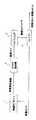
図1を参照して、強調された出力画像を取得するために特定の画像処理経路により画像を処理するための本発明の第1実施の形態が示されている。一般に、本発明は、画像に対してシフト不変の改善を実行する。改善の規模は、画像における物体のマテリアルコンテンツにより決定される。したがって、連続する画像に提供される改善は、イメージコンテンツに強く依存する。特定の画像に提供される改善の規模は、イメージコンテンツに適したものとなるために選択される。
【0022】
図1に示される第1実施の形態では、本発明は、シフト不変の鮮鋭化処理を実行する。鮮鋭化の規模は、画像における物体により決定される。したがって、連続する画像に提供される鮮鋭度は、イメージコンテンツに強く依存する。任意の特定の画像に提供される鮮鋭化の規模は、イメージコンテンツに適するように選択される。
【0023】
図1は、画像i(x,y)を例示している。該画像は、x0行及びy0列を有しており、画像に含まれる画素数を減少し、したがって、鮮鋭化パラメータを決定するために、本発明により要求される処理時間を減少するための画像サブサンプラ2に入力される。
【0024】
好ましくは、画像i(x,y)は、高解像度であり、たとえば、例示的な高解像度の画像は、x0=1024行の画素に、y0=1536列の画素を掛けたものである。画像サブサンプラ2から出力される画像は、m0行とn0列を有する低解像度の画像であり、たとえば、例示的な低解像度の画像は、m0=128にn0=192を掛けたものである。
【0025】
画像サブサンプラ2は、好ましくは、w×w画素ブロック(たとえば、w=8(先の例示的な画像に対応する))を通してブロック平均処理を実行して、画像サブサンプラ2から出力される低解像度の画像を生成する。大きな画像から小さな画像をつくる多くの他の方法は、画像処理の分野で公知であり、画像サブサンプラ2として使用することができる(先の例は本発明を限定するものではない。実際、画像サブサンプラは、追加の処理を許容することができる場合に省略することができる)。
【0026】
画像サブサンプラ2から出力される画像は、特定の画素又は画素からなる領域が所与のターゲットマテリアルを表現する信頼度を示す信頼マップの作成のためにマテリアル検出器4に入力される。ターゲットマテリアルは、画像の鮮鋭度が高感度であるマテリアルとして選択される。
【0027】
マテリアル検出器4は、好ましくは、画像検出器4に入力される画像の行及び列に関して同じ画素寸法を有している信頼マップM(m,n)を出力する。信頼マップは、特定の画素がターゲットマテリアルを表現する信頼性を示す。この信頼性は、確率として表現されることが好ましい。たとえば、それぞれの画素値M(m,n)は、(低解像度の画素(m,n)がターゲットマテリアルを表す)100*Pに等しい。P(A)は事象Aの確率を表している。
【0028】
代替的に、それぞれの画素値M(m,n)は、信頼性を示す2進区分を表している。たとえば、信頼マップにおける画素値1は、画素がターゲットマテリアルを表す信頼性を表し、画素値0は、画素がターゲットマテリアルを表していない信頼性を表している。
【0029】
好適な実施の形態では、ターゲットマテリアルは、人間の素肌である。M.W.Dupin及びJ.Luo等により“Method for Processing a Digital Image to Adjust Brightness”と題され、2001年7月12日に提出された係属している米国特許出願シリアル番号09/904,366号では、素肌のターゲットマテリアルについて信頼性を示す信頼マップを作成する方法が記載されている。
【0030】
さらに、人間の素肌のターゲットマテリアルについて信頼マップを作成する方法は、以下の論文に記載されている。K.Cho, J.Jang, K.Hongによる“Adaptive Skin-Color Filter” Pattern Recognition, 34(2001) 1067-1073; 及びM.Fleck, D.Forsyth, C.Breglerによる“Finding Naked People” Proceedings of the European Conference on Computer Vision, Vol.2, Vol.2, 1996, pp592-602。
【0031】
係属中の米国特許出願シリアル番号第09/904,366号に記載される方法は、皮膚の階調の領域について使用することができ、以下のように要約することができる。画像の画素RGBの値は、以下の式により“Lst”座標に変換される、
L=(R+G+B)/sqrt(3)
s=(R−B)/sqrt(2)
t=(2G−R−B)/sqrt(6)
入力されるカラーデジタル画像におけるそれぞれ画素について、皮膚の階調である確率が計算される。確率は、所定の皮膚の階調の確率関数に基づいて、Lst空間におけるその座標から導出される。これらの確率関数は、シーンバランスされた画像の大きな集合のおける皮膚及び非皮膚の領域の色空間分布のデータの集合に基づいて構築される。
【0032】
ある画素がそのLst座標での皮膚の階調の画素である条件付き確率は、以下の式で表される。
Pr(Skin|L,s,t)=Pr(Skin|L)*Pr(Skin|s)*Pr(Skin|t)
ここで、それぞれの条件付き確率Pr(Skin|L)、Pr(Skin|s)及びPr(Skin|t)は、皮膚及び非皮膚の画素について、ベイズ理論をオリジナルのトレイニング分布に適用することにより構築される。この方法論の更なる詳細は、上述した係属中の米国特許出願シリアル番号09/904,306号に見ることができ、参照により本実施の形態に組込まれる。
【0033】
比較において、皮膚の階調に色付けされた画素の検出のための他の慣習的な方法が存在する。たとえば、米国特許第4,203,671号(Takahashi)及び米国特許第5,781,276号(Zahn)では、尤度確率P(色/皮膚)を使用している。しかし、この慣習的な確率を使用する1つの問題点は、非皮膚階調の画素の確率分散が説明されないことである。結果的に、誤った検出について高い尤度が存在する。
【0034】
全ての画素についての確率の集合は、入力画像について皮膚の階調の確率分散を形成する。皮膚の階調の確率分散は、境界設定され、それぞれの画素が皮膚の階調又は非皮膚の階調として指定されるように2進マップが作成される。
【0035】
代替的に、顔の検出アルゴリズムを始めに使用して、入力されるカラーデジタル画像における人間の顔の領域を発見することができる。顔を検出する方法の説明については、Moghaddam及びPentlandによる(“Detection, recognition and Coding of Complex Objects Using Probabilistic Eigenspace Analysis”と題された)米国特許第5,710,833号を参照されたい。
【0036】
図2及び図3には、方法論の例が示されている。ここでは、図2が数人の画像を示し、図3が関連する信頼マップを示しており、ターゲットマテリアルが人間の皮膚である。画像の背景12は、低解像度画像における対応する画素がターゲットマテリアル(人間の皮膚)である信頼値0を有する画素から構成される。
【0037】
マテリアル検出器4が、低解像度画像の全ての画素がターゲットマテリアルを表す低い確率を有する場合、全体の信頼マップは、バックグランド12となる(好適な符号化では全て0)。図3は、非ゼロの信頼性を有する画素から構成される幾つかの領域を示している。
【0038】
たとえば、領域16は、低解像度画像における顔に対応し、たとえば、高い信頼値95を有する。領域14は腕に対応し、信頼値60を有する。領域18は、誤って信頼値40を有しており、木の枝が人間の素肌である信頼性を示している。かかる誤った信頼値は、誤った肯定である。一般に、マテリアル検出器4のような自動的な検出アルゴリズムは、誤った否定と同様に、領域18のような誤った肯定を生じる(たとえば、真の素肌を背景12として誤って分類する)。
【0039】
代替的に、ターゲットマテリアルは、自動化された方法が画像からマテリアルの信頼度を決定するために存在する人間の顔、空又は任意の他のマテリアルのような画像における他のタイプの物体のマテリアルコンテンツとすることができる。人間の顔の検出は、多くの論文において説明されている。たとえば、B.Heisele, T.Poggio, M.Pontil等による“Face Detection in Still Gray Images”MIT Artificial Intelligence Lab, Memo1687, May2000を参照されたい。
【0040】
さらに、(“Method for Detecting Sky in Images”と題され、J.Luo及びS.Etz等により1999年11月29日に提出された)係属中の米国特許出願シリアル番号09/450,190号には、ターゲットマテリアルが青い空である場合の信頼マップの作成が記載されている。
【0041】
信頼マップは、マップアナライザ8に入力される。マップアナライザ8は、信頼マップを分析して、1つ以上の鮮鋭化パラメータとして、画像の鮮鋭化についての推薦を出力する。鮮鋭化パラメータは、画像に適用される鮮鋭化のレベル又は強さに直接関連する任意のパラメータである。
【0042】
好適な実施の形態では、マップアナライザ8は、信頼マップの分析から導出されるスケールファクタβを出力する。一般に、鮮鋭化パラメータは、信頼マップの関数である。
【0043】
好適な実施の形態では、スケールファクタβは、信頼マップM(m,n)の関数であり、以下のように導出されることが好ましい。
【数1】
【0044】
先に説明したように、ターゲットマテリアルは、人間の素肌であることが好ましい。したがって、βmaterialは、素肌を含む画像についての理想的な鮮鋭化レベルである。一般的な非肌の画像は、肌を含む画像よりも多くの量により満足される程度に鮮鋭化されるために、好ましくは、βmaterial=1.5であり、βnon-material=5である。
【0045】
この例では、スケールファクタβは、信頼マップに含まれる素肌の最大の信頼値に基づいて決定される。なお、βmaterial,βnon-materialそれ自身は、画像又は画像システムの特性に関する関数である場合がある。たとえば、βmaterial,βnon-materialは、粒子のために高速フィルムについて減少される。
【0046】
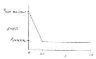
代替的に、スケールファクタは、信頼マップの他の特性に基づいて決定される。たとえば、スケールファクタβは、特別な信頼度を有する信頼マップの一部に基づいて計算される場合がある。たとえばβ=g(z)であり、ここで、
【数2】
【0047】
代替的に、スケールファクタは、信頼マップの他の特性に基づいて決定される場合がある。大きな素肌の領域は、過度の鮮鋭化処理に対して最も感度が高いことが観察される。これは、傷等の部分が迅速に明らかになるためである。しかし、素肌の領域が小さいとき、一般に画像は、問題となるアーチファクトの外観なしに、更に鮮鋭化される。
【0048】
図3に示されるように、好適なマテリアル検出器4は、上述した係属中の米国特許出願シリアル番号09/904,366号に記載されている。ここでは、Dupin及びLuoは、背景領域12から一般に構成される信頼マップを回復しており、全ての画素は、画素がターゲットマテリアル(人間の素肌)を表す確率が0であると推定されることを示す値0を有している。
【0049】
また、幾つかの前景領域14,16及び18が示されており、信頼マップは定数、それらの領域に属する全ての画素について画素がターゲットマテリアルを表す非ゼロの信頼値を示している。画像処理の技術分野において公知の連結されたコンポーネントアルゴリズムを使用することにより、非ゼロの信頼度を有するそれぞれの信頼領域は、信頼マップから抽出される。
【0050】
図3に示される例では、領域16のサイズは、領域18のサイズよりも大きな領域14のサイズよりも大きい。それぞれの信頼領域のサイズは、本明細書で説明された幾つかの手法のうちの1つを含めて、任意の数の手法により決定される。
【0051】
たとえば、サイズは、それぞれの信頼領域に属する画素数をカウントすることにより決定される。代替的に、(及び好ましくは)サイズは、それぞれの信頼領域に属する画素数とそれぞれの信頼領域の信頼マップにおける関連する値との積をとることにより決定される場合がある。
【0052】
鮮鋭化パラメータの値は、信頼領域のサイズの関数である。たとえば、β=h(z)であり、この場合、
【数3】
【0053】
マップアナライザ8により決定される鮮鋭化パラメータβは、シャープナー10に入力される。本発明の実施の形態では、鮮鋭化パラメータはスケーリングファクタβであるが、マップアナライザ8の機能は、かかる制限がなく、他の鮮鋭化に関連した決定は、当業者には明らかである。たとえば、シャープナー10により実行される鮮鋭化の畳み込みにおいて使用されるフィルタは、信頼マップの分析に基づいてマップアナライザ8により決定することができる。
【0054】
シャープナー10は、鮮鋭化パラメータを入力し、鮮鋭化パラメータを利用して、画像に鮮鋭化アルゴリズムを適用する。これにより、問題となる鮮鋭度のアーチファクトなしに、改善された鮮鋭度を有する強調された出力画像が生成される。好適な実施の形態では、シャープナー10は、強調された画像を生成するために決定された値βを使用して、アンシャープマスキングアルゴリズムを画像に適用する。
【0055】
たとえば、本発明に従う画像の鮮鋭化は、先に説明したアンシャープマスク処理による式において、目下説明されている鮮鋭化パラメータβの使用により実行することができる。
s(x,y)=i(x,y)**b(x,y)+βf(i(x,y)−i(x,y)**b(x,y))ここで、s(x,y)は強調された鮮鋭度により出力画像である。i(x,y)は入力された原画像である。b(x,y)は低域通過フィルタである。f( )はフリンジ関数である。**は2次元の畳み込みである。(x,y)は画像のx番目の行及びy番目の列である。βはマップアナライザ8により決定されるスケールファクタである。
【0056】
当業者であれば、(式(1)により与えられるような)アンシャープマスク処理を複数のチャネルを有するカラー画像に適用することができる幾つかの方法が存在することを認識されるであろう。たとえば、アンシャープマスク処理は、カラー画像のそれぞれのチャネルに適用することができる。好ましくは、アンシャープマスク処理は、一般に当該技術分野に知られているような、以下のやり方で適用される。
【0057】
入力画像は、赤、緑及び青色のチャネルから構成されるカラー画像であると仮定すると、はじめに、行列が画像に適用され、輝度チャネル及び2つ以上の色差チャネルが生成される。つぎに、アンシャープマスク処理が輝度チャネルに適用される。最後に、逆行列が幾つかのチャネルに適用され、強調されたカラー画像が生成される。
【0058】
さらに、アンシャープマスク処理は、1つのみの画像チャネル(たとえば、緑チャネル)に適用される場合があり、修正されたフリンジデータは、それぞれの色チャネルと加算され、強調されたカラー画像が生成される。アンシャープマスク処理へのこれら及び他の類似の修正及び強調は、当業者により良好に理解される。その使用の特殊性は、シフト不変の鮮鋭化のための鮮鋭化パラメータの方法に基本的に関連しないので、その特定の用途は、本発明を限定するものではない。
【0059】
また、当業者であれば、式(1)及び本発明は、アンシャープマスクにより実行されるものとして画像に適用される鮮鋭化を一般的に説明しているが、必ずしもこれに限らない。式(1)のフリンジ関数f( )が同じであると仮定すると、アンシャープマスク処理は、畳み込みで画像に適用することができる1つのフィルタとして常に再構成することができ、アンシャープマスクと同じ結果を得ることができる。
たとえば、フィルタ係数b(x,y)が以下に与えられるものとする。
【数4】
【数5】
【0060】
図6には、本発明の代替的な実施の形態が示されている。この実施の形態では、フィルタ20は、マップアナライザ8により決定されるパラメータに従い適用される。フィルタは、マップアナライザ8から出力されるフィルタパラメータに従い、画素にわたって一様に適用される。
【0061】
この実施の形態では、画像の特性は、鮮鋭ではなく、フィルタは、鮮鋭化フィルタではない、むしろ、画像の特性は、別のタイプの改善に関連されており、フィルタは、別のタイプのフィルタである。たとえば、画像特性は雑音であり、フィルタは、雑音低減フィルタである。たとえば、Jong-Sen Leeは、論文“Digital Image Smoothing and the Sigma Filter” Computer Vision, Graphics, and Image Processing, 24, 255-269, 1983でシグマフィルタを説明している。
【0062】
このシグマフィルタは、近傍の中央の画素を中央の画素からの強度であるΔコード内の全ての画素で置き換える。パラメータΔは、パラメータβが決定されるやり方と類似のやり方でマップアナライザ8により選択される。分析されるマテリアルコンテンツは、鮮鋭度について分析されるのと同じであるか、又は雑音に対して特に感度が高い幾つかの他のマテリアルコンテンツである場合がある。
【0063】
たとえば、ターゲットとなるマテリアルコンテンツが植物である場合、マップアナライザ8は、高い信頼値を有する領域を含む画像について小さな値のΔを出力し、高い信頼性による領域を有さない画像について大きな値のΔを出力する。
【図面の簡単な説明】
【図1】本発明の第1実施の形態による画像を改善するための技法を説明するブロック図である。
【図2】図1に示される画像を改善する技法に従い処理されるタイプの画像の例を示す図である。
【図3】ターゲットマテリアルが人間の素肌であるときの、図2に示される画像について、図1に示される画像を改善する技法により生成される信頼マップの例を示す図である。
【図4】図1に示される画像を改善する技法のためのスケールファクタβを決定するために使用される関数g(z)を表す図である。
【図5】図1に示される画像を改善する技法のためのスケールファクタβを決定するために使用される別の関数h(z)を表す図である。
【図6】本発明の第2実施の形態による画像を改善するための技法を説明するブロック図である。
【符号の説明】
2:画像サブサンプラ
4:マテリアル検出器
8:マップアナライザ
10:シャープナー
12:背景領域
14,16:信頼領域
18:誤って肯定となった信頼領域
20:フィルタ[0001]
BACKGROUND OF THE INVENTION
The present invention relates to the field of digital image processing, and more particularly to a method for associating processing parameters with image content.
[0002]
[Prior art]
In digital image processing, it is common practice to sharpen an image with a sharpening algorithm to emphasize details. Typically, this sharpening process is performed by a convolution process (see, for example, “Fundamentals of Digital Image Processing” by AKJain, Prentice-Hall: 1989, pp. 249-pp251). Processing using an unsharp mask is one example of sharpening processing based on convolution.
[0003]
For example, image sharpening with an unsharp mask can be described by the following equation.
s (x, y) = i (x, y) ** b (x, y) + βf (i (x, y) -i (x, y) ** b (x, y)) (1)
Here, s (x, y) is an output image by enhanced sharpening, i (x, y) is an input original image, b (x, y) is a low-pass filter, and β is an unsharp mask. The scale factor, f () is the fringe function, and (x, y) is the x th row and y th column of the image.
[0004]
Typically, an unsharp image is generated by convolution of the image with a low pass filter (ie, the unsharp image is given by i (x, y) ** b (x, y)). Next, the high-pass or fringe data is generated by subtracting the unsharp image from the original image (i.e., the high-pass data is i (x, y) -i (x, y) ** b (x, y)).
[0005]
This high pass data is then modified by either or both of the scale factor β and the fringe function f (). Finally, the corrected high-pass data is added to either the original image or the unsharp image to generate a sharpened image.
[0006]
Similar sharpening effects can be achieved by modifying the image in the frequency domain (eg, the FFT domain), as is well known in the digital signal processing field. Both spatial domain techniques (eg, convolution techniques) and frequency domain techniques that enhance image sharpness are shift invariant techniques. In other words, the sharpness process is invariant to position in the image.
[0007]
While these techniques certainly produce sharp images, the resulting image quality may vary depending on the image content. For example, using an unsharp mask algorithm may yield satisfactory results for a building image.
[0008]
However, using the same algorithm may result in an undesired overview that is over-sharpened for human face images (eg, scratches may be emphasized). The scale factor parameter may be individually modified for each scene by a human operator, but this is an expensive process.
[0009]
In US Pat. No. 5,682,443, Gouch and MacDonald et al. Describe a method for modifying parameters associated with an unsharp mask on a pixel-by-pixel basis. Essentially, the scale factor β, which is a constant in equation (1), is replaced with a scale factor that changes based on the position β (x, y). These parameters are varied based on the color of the pixel in the local neighborhood.
[0010]
[Problems to be solved by the invention]
This technique makes it possible to emphasize less details about pixels that are approximately skin-colored. However, this method is not shift invariant. This is because the fringe data is corrected by a weighting function determined according to the value of the sharp data or unsharp data for each color component of each pixel.
[0011]
As a result, this approach is computationally intensive because the filter parameters are varied for each pixel. In addition, this approach generates switching artifacts when one region of the image is sharpened as well as nearby regions.
[0012]
In this way, there is a need to quickly sharpen or otherwise improve an image that can adjust the overall improvement of the image based on the material content of the image without generating switching artifacts. Exists.
[0013]
[Means for Solving the Problems]
The present invention is directed to overcoming one or more of the problems set forth above. Briefly described, according to one aspect of the present invention, a method for improving the characteristics of an image according to its material content comprises providing an image comprising pixels and a trust map spatially corresponding to the pixels. Generating, improving parameters from the confidence map, and using the improved parameters to improve image characteristics. Here, the confidence map includes a confidence value indicating the likelihood that each pixel represents a specific material. The improvement parameter is applied uniformly to the pixels.
[0014]
The present invention has the advantage that the overall level of image characteristics is varied depending on the material detected in the image. When this property is sharpness, rather than adjusting the system to sharpen the entire image at a conservative level so as not to create sharpness artifacts in an image, the system according to the present invention is It automatically decides to sharpen the sensitivity image conservatively, actively sharpen the low sensitivity image, and sharpen each image.
[0015]
In particular, the system of the present invention conservatively sharpens images in which human skin is detected, and actively sharpens images in which human skin is not detected. In another aspect, the system according to the present invention conservatively reduces noise in areas of the image where noise reduction may result in undesirable artifacts, such as in plant images, and such sensitive material content is reduced. For images that are not detected, noise is actively reduced.
These and other aspects, objects, features and advantages of the present invention will be clearly understood from a consideration of the following detailed description of preferred embodiments and with reference to the accompanying drawings.
[0016]
DETAILED DESCRIPTION OF THE INVENTION
In the following description, the embodiment of the present invention is described as a method realized as a software program. Those skilled in the art will readily recognize that such software equivalent concepts are built in hardware. Since image enhancement algorithms and methods are known, the description herein is particularly directed to elements that form part of the method and system according to the invention, and elements that are more directly linked to the method and system.
[0017]
Other elements, hardware and / or software that generate or otherwise process the image signal are not specifically illustrated or described, but may be selected from such materials. Given the systems and methods illustrated and described in accordance with the present invention in the following materials, the software not specifically illustrated, described or proposed in this embodiment useful for the implementation of the present invention is conventional. And falls under normal knowledge in the technical field.
[0018]
In addition, as used in the present embodiment, the computer program may be stored in a computer-readable storage medium, such as a magnetic disk (a hard disk drive or a floppy disk). A magnetic storage medium such as an optical storage medium (optical disc, optical tape or machine-read barcode), a solid-state electronic storage device such as a random access memory (RAM), a read-only memory (ROM), or a computer program Any other physical device or medium used to do this.
[0019]
A digital image is typically a two-dimensional array of red, green and blue pixel values or a number of monochromatic pixel values corresponding to light intensity. With respect to terminology, the value of the pixel of the digital image located at the coordinates (x, y) to which the xth row and yth column digital image is referenced is the red, green and A triplet of values [r (x, y), g (x, y), b (x, y)], to which the values of the blue digital image channel are respectively referred, is provided.
[0020]
In this regard, a digital image is considered as having a predetermined number of digital image channels. If the digital image comprises a two-dimensional array of red, green and blue, the image comprises three channels, the so-called red, green and blue spectral channels.
[0021]
Referring to FIG. 1, a first embodiment of the present invention for processing an image with a specific image processing path to obtain an enhanced output image is shown. In general, the present invention performs shift invariant improvement on an image. The magnitude of the improvement is determined by the material content of the object in the image. Thus, the improvement provided for successive images is strongly dependent on the image content. The scale of improvement provided for a particular image is selected to be suitable for the image content.
[0022]
In the first embodiment shown in FIG. 1, the present invention performs a shift invariant sharpening process. The magnitude of sharpening is determined by the objects in the image. Therefore, the sharpness provided to successive images is strongly dependent on the image content. The amount of sharpening provided to any particular image is selected to suit the image content.
[0023]
FIG. 1 illustrates an image i (x, y). The image is x0 Line and y0 In order to reduce the number of pixels contained in the image and thus to determine the sharpening parameters, it is input to the
[0024]
Preferably, the image i (x, y) is high resolution, for example the exemplary high resolution image is x0 = 1024 rows of pixels, y0 = 1536 rows of pixels multiplied. The image output from the
[0025]
The
[0026]
The image output from the
[0027]
The material detector 4 preferably outputs a confidence map M (m, n) having the same pixel dimensions with respect to the rows and columns of the image input to the image detector 4. The trust map indicates the reliability with which a particular pixel represents the target material. This reliability is preferably expressed as a probability. For example, each pixel value M (m, n) is equal to 100 * P (where the low resolution pixel (m, n) represents the target material). P (A) represents the probability of event A.
[0028]
Alternatively, each pixel value M (m, n) represents a binary partition indicating reliability. For example, the pixel value 1 in the trust map represents the reliability that the pixel represents the target material, and the
[0029]
In a preferred embodiment, the target material is human skin. MWDupin and J. Luo et al. Entitled “Method for Processing a Digital Image to Adjust Brightness” and pending US patent application serial number 09 / 904,366 filed on July 12, 2001, A method of creating a trust map that shows the reliability of a material is described.
[0030]
Furthermore, a method for creating a trust map for the target material of human bare skin is described in the following paper. “Adaptive Skin-Color Filter” Pattern Recognition, 34 (2001) 1067-1073 by K.Cho, J.Jang, K.Hong; and “Finding Naked People” Proceedings of M.Fleck, D.Forsyth, C.Bregler the European Conference on Computer Vision, Vol.2, Vol.2, 1996, pp592-602.
[0031]
The method described in pending US patent application Serial No. 09 / 904,366 can be used for skin tone areas and can be summarized as follows. The pixel RGB values of the image are converted to “Lst” coordinates by the following formula:
L = (R + G + B) / sqrt (3)
s = (R−B) / sqrt (2)
t = (2G-RB) / sqrt (6)
For each pixel in the input color digital image, the probability of being a skin tone is calculated. Probabilities are derived from their coordinates in Lst space based on a predetermined skin tone probability function. These probability functions are constructed based on a collection of color space distribution data for skin and non-skin regions in a large set of scene-balanced images.
[0032]
The conditional probability that a pixel is a skin tone pixel at the Lst coordinate is expressed by the following equation.
Pr (Skin | L, s, t) = Pr (Skin | L) * Pr (Skin | s) * Pr (Skin | t)
Where each conditional probability Pr (Skin | L), Pr (Skin | s) and Pr (Skin | t) apply Bayesian theory to the original training distribution for skin and non-skin pixels. It is constructed by. Further details of this methodology can be found in the above-mentioned pending US patent application serial number 09 / 904,306, which is incorporated herein by reference.
[0033]
In comparison, there are other conventional methods for the detection of pixels colored in skin tones. For example, US Pat. No. 4,203,671 (Takahashi) and US Pat. No. 5,781,276 (Zahn) use the likelihood probability P (color / skin). However, one problem using this conventional probability is that the probability distribution of non-skin gray pixels is not accounted for. As a result, there is a high likelihood for false detection.
[0034]
The set of probabilities for all pixels forms a skin tone probability variance for the input image. The skin tone probability variance is demarcated and a binary map is created so that each pixel is designated as a skin tone or non-skin tone.
[0035]
Alternatively, a face detection algorithm can be used initially to find human face regions in the input color digital image. For a description of how to detect faces, see US Pat. No. 5,710,833 (titled “Detection, recognition and Coding of Complex Objects Using Probabilistic Eigenspace Analysis”) by Moghaddam and Pentland.
[0036]
2 and 3 show example methodologies. Here, FIG. 2 shows images of several people, FIG. 3 shows an associated trust map, and the target material is human skin. The
[0037]
If the material detector 4 has a low probability that every pixel of the low resolution image represents the target material, the overall confidence map will be the background 12 (all 0 in the preferred encoding). FIG. 3 shows several regions composed of pixels with non-zero reliability.
[0038]
For example,
[0039]
Alternatively, the target material is the material content of other types of objects in the image, such as a human face, sky or any other material where an automated method exists to determine the reliability of the material from the image. It can be. Human face detection has been described in many papers. See, for example, “Face Detection in Still Gray Images” by MIT Artificial Intelligence Lab, Memo 1687, May 2000 by B. Heisele, T. Poggio, M. Pontil et al.
[0040]
In addition, pending US patent application serial number 09 / 450,190 (titled “Method for Detecting Sky in Images”, filed November 29, 1999 by J. Luo and S. Etz et al.) The creation of a trust map when the target material is a blue sky is described.
[0041]
The trust map is input to the
[0042]
In the preferred embodiment, the
[0043]
In a preferred embodiment, the scale factor β is a function of the confidence map M (m, n) and is preferably derived as follows:
[Expression 1]
[0044]
As described above, the target material is preferably human skin. Therefore, βmaterial Is the ideal sharpening level for images containing bare skin. A typical non-skin image is preferably sharpened to a degree that is satisfied by a greater amount than an image containing skin.material = 1.5 and βnon-material = 5.
[0045]
In this example, the scale factor β is determined based on the maximum confidence value of the bare skin included in the confidence map. Βmaterial , Βnon-material As such, it may be a function of the characteristics of the image or image system. For example, βmaterial , Βnon-material Is reduced for high speed films due to particles.
[0046]
Alternatively, the scale factor is determined based on other characteristics of the trust map. For example, the scale factor β may be calculated based on a portion of a trust map having a special confidence level. For example, β = g (z), where
[Expression 2]
[0047]
Alternatively, the scale factor may be determined based on other characteristics of the trust map. It is observed that large bare skin areas are most sensitive to excessive sharpening. This is because parts such as scratches are quickly revealed. However, when the bare skin area is small, the image is generally sharpened further without the appearance of problematic artifacts.
[0048]
As shown in FIG. 3, a suitable material detector 4 is described in the above-mentioned pending US patent application serial number 09 / 904,366. Here, Dupin and Luo have recovered the trust map generally constructed from the
[0049]
Also shown are several
[0050]
In the example shown in FIG. 3, the size of the
[0051]
For example, the size is determined by counting the number of pixels belonging to each confidence region. Alternatively, (and preferably) the size may be determined by taking the product of the number of pixels belonging to each confidence region and the associated value in the confidence map of each confidence region.
[0052]
The value of the sharpening parameter is a function of the size of the confidence region. For example, β = h (z), where
[Equation 3]
[0053]
The sharpening parameter β determined by the
[0054]
The
[0055]
For example, the sharpening of an image according to the present invention can be performed by using the sharpening parameter β currently described in the formula by the unsharp mask process described above.
s (x, y) = i (x, y) ** b (x, y) + βf (i (x, y) -i (x, y) ** b (x, y)) where s ( x, y) is an output image with enhanced sharpness. i (x, y) is the input original image. b (x, y) is a low-pass filter. f () is a fringe function. ** is a two-dimensional convolution. (x, y) is the xth row and yth column of the image. β is a scale factor determined by the
[0056]
One skilled in the art will recognize that there are several ways in which unsharp masking (as given by equation (1)) can be applied to a color image having multiple channels. . For example, unsharp mask processing can be applied to each channel of a color image. Preferably, unsharp masking is applied in the following manner, as is generally known in the art.
[0057]
Assuming that the input image is a color image composed of red, green and blue channels, first a matrix is applied to the image to generate a luminance channel and two or more color difference channels. Next, unsharp masking is applied to the luminance channel. Finally, an inverse matrix is applied to several channels to produce an enhanced color image.
[0058]
In addition, unsharp masking may be applied to only one image channel (eg, the green channel), and the modified fringe data is added to each color channel to produce an enhanced color image. Is done. These and other similar modifications and enhancements to unsharp masking are well understood by those skilled in the art. Its particular use is not fundamentally related to the method of sharpening parameters for shift-invariant sharpening, so its particular application does not limit the invention.
[0059]
Further, although those skilled in the art generally describe sharpening applied to an image as being performed by an unsharp mask, Equation (1) and the present invention are not necessarily limited thereto. Assuming that the fringe function f () in equation (1) is the same, the unsharp mask process can always be reconstructed as a single filter that can be applied to the image by convolution and is the same as the unsharp mask The result can be obtained.
For example, assume that the filter coefficient b (x, y) is given below.
[Expression 4]
[Equation 5]
[0060]
FIG. 6 shows an alternative embodiment of the present invention. In this embodiment, the
[0061]
In this embodiment, the image characteristics are not sharp and the filter is not a sharpening filter; rather, the image characteristics are associated with another type of improvement and the filter is a different type of filter. It is. For example, the image characteristic is noise, and the filter is a noise reduction filter. For example, Jong-Sen Lee describes a sigma filter in the paper “Digital Image Smoothing and the Sigma Filter” Computer Vision, Graphics, and Image Processing, 24, 255-269, 1983.
[0062]
This sigma filter replaces the central pixel in the vicinity with all the pixels in the Δ code, which is the intensity from the central pixel. The parameter Δ is selected by the
[0063]
For example, when the target material content is a plant, the
[Brief description of the drawings]
FIG. 1 is a block diagram illustrating a technique for improving an image according to a first embodiment of the present invention.
FIG. 2 is a diagram illustrating an example of a type of image that is processed in accordance with the technique for improving the image shown in FIG.
3 is a diagram showing an example of a trust map generated by a technique for improving the image shown in FIG. 1 for the image shown in FIG. 2 when the target material is human skin.
FIG. 4 is a diagram representing a function g (z) used to determine a scale factor β for the technique for improving the image shown in FIG.
FIG. 5 is a diagram representing another function h (z) used to determine a scale factor β for the technique for improving the image shown in FIG.
FIG. 6 is a block diagram illustrating a technique for improving an image according to a second embodiment of the present invention.
[Explanation of symbols]
2: Image subsampler
4: Material detector
8: Map analyzer
10: Sharpener
12: Background area
14,16: Trust area
18: Confidence area that was falsely affirmed
20: Filter
Claims (3)
Translated fromJapanese画素からなる画像を提供するステップと、
それぞれの画素が特定のマテリアルを表現する尤度を示す信頼値を含む信頼マップを、前記画素に空間的に対応して生成するステップと、
前記信頼値に比例し、前記画素に一様に適用される改善パラメータを、前記信頼マップの前記信頼値から生成するステップと、
前記画像の特性を改善するために、前記改善パラメータを使用するステップとを備え、
前記改善パラメータは、鮮鋭度であり;前記マテリアルコンテンツは、素肌であり;前記信頼値は、少なくとも1つの大きな素肌の領域、少なくとも1つの小さな素肌の領域、および背景の領域に空間的にグループ化され;かつ前記少なくとも1つの大きな素肌の領域が存在する場合には、前記少なくとも1つの大きな素肌の領域が存在ぜずかつ前記少なくとも1つの小さな素肌の領域が存在する場合よりも弱い鮮鋭化を示すよう前記改善パラメータが生成され、いずれの前記素肌の領域も存在せずかつ前記背景の領域が存在する場合には、いずれの前記素肌の領域が存在するよりも強い鮮鋭化を示すよう前記改善パラメータが生成される、
ことを特徴とする方法。A method for improving image characteristics according to material content,
Providing an image of pixels;
Generating a confidence map including a confidence value indicating the likelihood that each pixel represents a particular material, spatially corresponding to the pixel;
Generating an improvement parameter proportional to the confidence value and applied uniformly to the pixels from the confidence value of the confidence map;
Using the improvement parameter to improve the characteristics of the image,
The improvement parameter is sharpness; the material content is bare skin; and the confidence value is spatially grouped into at least one large bare area, at least one small bare area, and a background area. is; andwhen said at least one region of major skinis present, thesaid no ze there is at least one region of large skin of and said at least one sharpeningweak thanwhen an area of the small skinis presentis the improved parameter generation as shown, any of theIfarea of skin is alsothat there is an area ofnot and the backgroundexists,the to indicate the sharpeningstrong than the area of any of the skinis presentImprovement parameters are generated ,
A method characterized by that.
ことを特徴とする請求項1記載の方法。Using the improvement parameter comprises performing sharpening with unsharp masking;
The method of claim 1 wherein:
ことを特徴とする請求項1記載の方法。The improvement parameter is proportional to one of a maximum confidence value and an average confidence value;
The method of claim 1 wherein:
Applications Claiming Priority (2)
| Application Number | Priority Date | Filing Date | Title |
|---|---|---|---|
| US10/020,031US7050636B2 (en) | 2001-12-07 | 2001-12-07 | Method and system for improving an image characteristic based on image content |
| US020031 | 2001-12-07 |
Publications (2)
| Publication Number | Publication Date |
|---|---|
| JP2003196653A JP2003196653A (en) | 2003-07-11 |
| JP4498671B2true JP4498671B2 (en) | 2010-07-07 |
Family
ID=21796353
Family Applications (1)
| Application Number | Title | Priority Date | Filing Date |
|---|---|---|---|
| JP2002339710AExpired - Fee RelatedJP4498671B2 (en) | 2001-12-07 | 2002-11-22 | Method and system for improving image characteristics based on image content |
Country Status (4)
| Country | Link |
|---|---|
| US (1) | US7050636B2 (en) |
| EP (1) | EP1324265B1 (en) |
| JP (1) | JP4498671B2 (en) |
| DE (1) | DE60235292D1 (en) |
Families Citing this family (32)
| Publication number | Priority date | Publication date | Assignee | Title |
|---|---|---|---|---|
| US7064740B2 (en)* | 2001-11-09 | 2006-06-20 | Sharp Laboratories Of America, Inc. | Backlit display with improved dynamic range |
| US7092573B2 (en)* | 2001-12-10 | 2006-08-15 | Eastman Kodak Company | Method and system for selectively applying enhancement to an image |
| DE60314851D1 (en)* | 2003-05-19 | 2007-08-23 | St Microelectronics Sa | Image processing method for numerical images with exposure correction by detection of skin areas of the object |
| US7024022B2 (en)* | 2003-07-30 | 2006-04-04 | Xerox Corporation | System and method for measuring and quantizing document quality |
| JP2005141477A (en)* | 2003-11-06 | 2005-06-02 | Noritsu Koki Co Ltd | Image sharpening processing method and image processing apparatus for implementing the method |
| WO2005052673A2 (en)* | 2003-11-21 | 2005-06-09 | Sharp Laboratories Of America, Inc. | Liquid crystal display with adaptive color |
| JP4659354B2 (en)* | 2003-12-02 | 2011-03-30 | キヤノン株式会社 | Image processing method and apparatus |
| US7612757B2 (en) | 2004-05-04 | 2009-11-03 | Sharp Laboratories Of America, Inc. | Liquid crystal display with modulated black point |
| US8395577B2 (en) | 2004-05-04 | 2013-03-12 | Sharp Laboratories Of America, Inc. | Liquid crystal display with illumination control |
| US7602369B2 (en) | 2004-05-04 | 2009-10-13 | Sharp Laboratories Of America, Inc. | Liquid crystal display with colored backlight |
| US7505018B2 (en) | 2004-05-04 | 2009-03-17 | Sharp Laboratories Of America, Inc. | Liquid crystal display with reduced black level insertion |
| US7532192B2 (en) | 2004-05-04 | 2009-05-12 | Sharp Laboratories Of America, Inc. | Liquid crystal display with filtered black point |
| US7872631B2 (en) | 2004-05-04 | 2011-01-18 | Sharp Laboratories Of America, Inc. | Liquid crystal display with temporal black point |
| US7777714B2 (en) | 2004-05-04 | 2010-08-17 | Sharp Laboratories Of America, Inc. | Liquid crystal display with adaptive width |
| CN101685536B (en)* | 2004-06-09 | 2011-11-30 | 松下电器产业株式会社 | image processing method |
| KR100618849B1 (en)* | 2004-07-22 | 2006-09-01 | 삼성전자주식회사 | Apparatus and method for filtering blocking phenomenon in video |
| KR100565209B1 (en)* | 2004-08-11 | 2006-03-30 | 엘지전자 주식회사 | Apparatus and Method for Improving Image Clarity Based on Human Visual System |
| US7898519B2 (en) | 2005-02-17 | 2011-03-01 | Sharp Laboratories Of America, Inc. | Method for overdriving a backlit display |
| US8050511B2 (en) | 2004-11-16 | 2011-11-01 | Sharp Laboratories Of America, Inc. | High dynamic range images from low dynamic range images |
| US7525528B2 (en) | 2004-11-16 | 2009-04-28 | Sharp Laboratories Of America, Inc. | Technique that preserves specular highlights |
| US8050512B2 (en)* | 2004-11-16 | 2011-11-01 | Sharp Laboratories Of America, Inc. | High dynamic range images from low dynamic range images |
| JP2006215785A (en)* | 2005-02-03 | 2006-08-17 | Ricoh Co Ltd | Image processing method, image processing apparatus, image processing program, and recording medium |
| US7473745B2 (en)* | 2005-09-02 | 2009-01-06 | Equistar Chemicals, Lp | Preparation of multimodal polyethylene |
| US9143657B2 (en) | 2006-01-24 | 2015-09-22 | Sharp Laboratories Of America, Inc. | Color enhancement technique using skin color detection |
| US8121401B2 (en)* | 2006-01-24 | 2012-02-21 | Sharp Labortories of America, Inc. | Method for reducing enhancement of artifacts and noise in image color enhancement |
| US8941580B2 (en) | 2006-11-30 | 2015-01-27 | Sharp Laboratories Of America, Inc. | Liquid crystal display with area adaptive backlight |
| US8031961B2 (en)* | 2007-05-29 | 2011-10-04 | Hewlett-Packard Development Company, L.P. | Face and skin sensitive image enhancement |
| US7933454B2 (en)* | 2007-06-25 | 2011-04-26 | Xerox Corporation | Class-based image enhancement system |
| JP5349790B2 (en)* | 2007-11-16 | 2013-11-20 | キヤノン株式会社 | Image processing apparatus, image processing method, and program |
| US8295557B2 (en)* | 2009-01-12 | 2012-10-23 | Arcsoft Hangzhou Co., Ltd. | Face image processing method |
| CN111127307A (en)* | 2019-12-09 | 2020-05-08 | 上海传英信息技术有限公司 | Image processing method, apparatus, electronic device, and computer-readable storage medium |
| US11488285B2 (en)* | 2020-04-13 | 2022-11-01 | Apple Inc. | Content based image processing |
Family Cites Families (20)
| Publication number | Priority date | Publication date | Assignee | Title |
|---|---|---|---|---|
| JPS52156624A (en) | 1976-06-22 | 1977-12-27 | Fuji Photo Film Co Ltd | Detection of skin color of color film |
| US5781276A (en) | 1992-07-27 | 1998-07-14 | Agfa-Gevaert Ag | Printing of color film |
| DE69428148T2 (en)* | 1993-03-24 | 2002-05-29 | Fujifilm Electronic Imaging Ltd., London | Color change of pictures |
| US5889578A (en)* | 1993-10-26 | 1999-03-30 | Eastman Kodak Company | Method and apparatus for using film scanning information to determine the type and category of an image |
| US5710833A (en) | 1995-04-20 | 1998-01-20 | Massachusetts Institute Of Technology | Detection, recognition and coding of complex objects using probabilistic eigenspace analysis |
| JP3490559B2 (en)* | 1995-11-14 | 2004-01-26 | 富士写真フイルム株式会社 | Method for determining main part of image and method for determining copy conditions |
| JP3733165B2 (en)* | 1996-02-27 | 2006-01-11 | 富士写真フイルム株式会社 | Image data conversion method for digital printer |
| US6453069B1 (en)* | 1996-11-20 | 2002-09-17 | Canon Kabushiki Kaisha | Method of extracting image from input image using reference image |
| US5867606A (en)* | 1997-08-12 | 1999-02-02 | Hewlett-Packard Company | Apparatus and method for determining the appropriate amount of sharpening for an image |
| JPH1191169A (en)* | 1997-09-19 | 1999-04-06 | Fuji Photo Film Co Ltd | Image processing apparatus |
| JP3506958B2 (en)* | 1998-09-10 | 2004-03-15 | 富士写真フイルム株式会社 | Image processing method, image processing apparatus, and recording medium |
| JP3455123B2 (en)* | 1998-12-24 | 2003-10-14 | 大日本スクリーン製造株式会社 | Image sharpness enhancement method and recording medium recording program for executing the processing |
| US6282317B1 (en)* | 1998-12-31 | 2001-08-28 | Eastman Kodak Company | Method for automatic determination of main subjects in photographic images |
| JP2001119575A (en)* | 1999-10-15 | 2001-04-27 | Ricoh Co Ltd | Image processing device |
| JP4064031B2 (en)* | 2000-01-31 | 2008-03-19 | 富士フイルム株式会社 | Image processing method |
| US6707940B1 (en)* | 2000-03-31 | 2004-03-16 | Intel Corporation | Method and apparatus for image segmentation |
| US6738494B1 (en)* | 2000-06-23 | 2004-05-18 | Eastman Kodak Company | Method for varying an image processing path based on image emphasis and appeal |
| US6731821B1 (en)* | 2000-09-29 | 2004-05-04 | Hewlett-Packard Development Company, L.P. | Method for enhancing compressibility and visual quality of scanned document images |
| US7092573B2 (en)* | 2001-12-10 | 2006-08-15 | Eastman Kodak Company | Method and system for selectively applying enhancement to an image |
| US6891977B2 (en)* | 2002-02-27 | 2005-05-10 | Eastman Kodak Company | Method for sharpening a digital image without amplifying noise |
- 2001
- 2001-12-07USUS10/020,031patent/US7050636B2/ennot_activeExpired - Lifetime
- 2002
- 2002-11-22JPJP2002339710Apatent/JP4498671B2/ennot_activeExpired - Fee Related
- 2002-11-25EPEP02079890Apatent/EP1324265B1/ennot_activeExpired - Lifetime
- 2002-11-25DEDE60235292Tpatent/DE60235292D1/ennot_activeExpired - Lifetime
Also Published As
| Publication number | Publication date |
|---|---|
| US20030108245A1 (en) | 2003-06-12 |
| JP2003196653A (en) | 2003-07-11 |
| EP1324265A3 (en) | 2006-08-16 |
| US7050636B2 (en) | 2006-05-23 |
| EP1324265B1 (en) | 2010-02-10 |
| DE60235292D1 (en) | 2010-03-25 |
| EP1324265A2 (en) | 2003-07-02 |
Similar Documents
| Publication | Publication Date | Title |
|---|---|---|
| JP4498671B2 (en) | Method and system for improving image characteristics based on image content | |
| EP1318475B1 (en) | A method and system for selectively applying enhancement to an image | |
| JP4460839B2 (en) | Digital image sharpening device | |
| Shin et al. | Radiance–reflectance combined optimization and structure-guided $\ell _0 $-Norm for single image dehazing | |
| US10339643B2 (en) | Algorithm and device for image processing | |
| EP1174824B1 (en) | Noise reduction method utilizing color information, apparatus, and program for digital image processing | |
| JP3775782B2 (en) | Method for detecting skin color in digital images | |
| KR101194481B1 (en) | Adjusting digital image exposure and tone scale | |
| EP1347415B1 (en) | Method for sharpening a digital image without amplifying noise | |
| US6621937B1 (en) | Removing chroma noise from digital images by using variable shape pixel neighborhood regions | |
| EP1372109A2 (en) | Method and system for enhancing portrait images | |
| JP2003198850A (en) | Digital color image processing method | |
| JP2001005960A (en) | Method and device for processing image | |
| JP2001126075A (en) | Image processing method and apparatus, and recording medium | |
| JP2000050081A (en) | Automatic tone control method by contrast gain control of edge | |
| JP2002300402A (en) | Image processor, processing method and recording medium | |
| JP2019016117A (en) | Image adjustment apparatus, local contrast amount calculation apparatus, method, and program | |
| US20060056722A1 (en) | Edge preserving method and apparatus for image processing | |
| JP7592932B1 (en) | Iterative graph-based image enhancement with object separation | |
| KR101468433B1 (en) | Apparatus and method for extending dynamic range using combined color-channels transmission map | |
| Supraja et al. | Lime: Low-light image enhancement via illumination map estimation | |
| JP4445026B2 (en) | Image processing method, apparatus, and program | |
| Pardhi et al. | Contrast enhancement using adaptive threshold based dynamic range adjustment in luv colour space | |
| Kumari et al. | An analytical review on image enhancement techniques | |
| Haslam et al. | Color Restoration Survey and an Overdetermined System for Color Retrieval from Faded Images |
Legal Events
| Date | Code | Title | Description |
|---|---|---|---|
| A621 | Written request for application examination | Free format text:JAPANESE INTERMEDIATE CODE: A621 Effective date:20051025 | |
| A131 | Notification of reasons for refusal | Free format text:JAPANESE INTERMEDIATE CODE: A131 Effective date:20080520 | |
| A601 | Written request for extension of time | Free format text:JAPANESE INTERMEDIATE CODE: A601 Effective date:20080819 | |
| A602 | Written permission of extension of time | Free format text:JAPANESE INTERMEDIATE CODE: A602 Effective date:20080822 | |
| A521 | Request for written amendment filed | Free format text:JAPANESE INTERMEDIATE CODE: A523 Effective date:20080917 | |
| A131 | Notification of reasons for refusal | Free format text:JAPANESE INTERMEDIATE CODE: A131 Effective date:20081125 | |
| A601 | Written request for extension of time | Free format text:JAPANESE INTERMEDIATE CODE: A601 Effective date:20090223 | |
| A602 | Written permission of extension of time | Free format text:JAPANESE INTERMEDIATE CODE: A602 Effective date:20090226 | |
| A521 | Request for written amendment filed | Free format text:JAPANESE INTERMEDIATE CODE: A523 Effective date:20090408 | |
| A131 | Notification of reasons for refusal | Free format text:JAPANESE INTERMEDIATE CODE: A131 Effective date:20090609 | |
| A02 | Decision of refusal | Free format text:JAPANESE INTERMEDIATE CODE: A02 Effective date:20091013 | |
| A521 | Request for written amendment filed | Free format text:JAPANESE INTERMEDIATE CODE: A523 Effective date:20100113 | |
| A911 | Transfer to examiner for re-examination before appeal (zenchi) | Free format text:JAPANESE INTERMEDIATE CODE: A911 Effective date:20100308 | |
| TRDD | Decision of grant or rejection written | ||
| A01 | Written decision to grant a patent or to grant a registration (utility model) | Free format text:JAPANESE INTERMEDIATE CODE: A01 Effective date:20100330 | |
| A01 | Written decision to grant a patent or to grant a registration (utility model) | Free format text:JAPANESE INTERMEDIATE CODE: A01 | |
| A61 | First payment of annual fees (during grant procedure) | Free format text:JAPANESE INTERMEDIATE CODE: A61 Effective date:20100414 | |
| FPAY | Renewal fee payment (event date is renewal date of database) | Free format text:PAYMENT UNTIL: 20130423 Year of fee payment:3 | |
| R150 | Certificate of patent or registration of utility model | Free format text:JAPANESE INTERMEDIATE CODE: R150 | |
| LAPS | Cancellation because of no payment of annual fees | ||
| S111 | Request for change of ownership or part of ownership | Free format text:JAPANESE INTERMEDIATE CODE: R313113 | |
| R350 | Written notification of registration of transfer | Free format text:JAPANESE INTERMEDIATE CODE: R350 |